1 Quantum physics (quantum theory, quantum mechanics) Part 3.
SPECIALIZED
TELEVISION [NGINE[RING
TELEVISION TECHNICAL ASSIGNMENT
ELECTRON PHYSICS AND ELECTRON THEORY
Copyright 1947 by
Capitol Radio Engineering Institute
Washington, D. C.
www.americanradiohistory.com

ELECTRON PHYSICS AND ELECTRON THEORY
FOREWORD
It requires little imagination in this era of atomic energy
and the atomic bomb to appreciate the importance in any technical
field of a modern understanding of the structure of matter. In the
daily press and in the semi -technical magazines we read about the
new and tremendous importance of the rare elements Uranium and
Thorium, and the man -made element Plutonium. Still, in CREI assign-
ments of almost 20 years a.go we studied the use of thorium in the manu-
facturer of filaments for radio tubes and also the structure of the
atom.
Radio and-television in their modern aspects are extremely
dependent upon the characteristics of the various elements. The long
life and low power consumption of modern receiving tubes is due to the
high electron- emitting characteristics of certain of the rare earths
wnen heated to moderate temperature. The highly sensitive television
pickup tube is made possible by the fact that the rare element caesium
in an oxide combination with silver emits electrons freely when light
shines on it. The television picture tube (kinescope) operates because
of the fact that certain phosphors emit visible light when struck by
a fast -moving beam of electrons proceeding through an evacuated space,
and the intensity of the light varies in accordance with the intensity
of the electron beam.
The vacuum tube which makes modern radio possible functions
because certain elements, when heated, will emit electrons into the
surrounding evacuated space, and these emitted electrons can be drawn
through space from one tube electrode to another and accurately con-
trolled by the application of positive and negative voltages to the
tube components.
Finally, we find that such elementary factors as positive
and negative voltages are due to the fact that electrons in various
pieces of apparatus and in their connecting wires, can become dis-
associated from particular atoms and can move quite freely through
the so- called solid substances so that an excess of electrons ac-
www.americanradiohistory.com
ELECTRON PHYSICS AND ELECTRON THEORY
cumulates at one point and a deficiency at another.
It is shown that the only difference between what we call a
conductor and what we call an insulator lies in the structure of the
atoms and molecules making up these two substances -that under certain
conditions the "resistance of a conductor will greatly increase and that
under other conditions an insulator will break down and become a conductor.
In addition to the great importance of this assignment to
the radiò and television engineer and technician, he will find it
extremely interesting. His entire professional career is based upon
the fact that molecules, atoms and electrons behave as they do. His
basic job is to understand that behavior and the methods of con-
trolling it.
E. H. Rietzke,
President.
www.americanradiohistory.com

- TABLE OF CONTENTS -
ELECTRON PHYSICS AND ELECTRON THEORY
COMPOSITION OF MATTER
FUNDAMENTAL PARTICLES
Pag e
2
2
Electrons and Protons 2
Coulomb's Law 4
Neutrons 6
Other Particles 6
THE ATOM 6
Combcsition of the Aton 7
The Nucleus 8
Mo re Comb l ex .4t on; s 10
CHEMICAL REACTIONS 13
Valence 13
Atonic Number 14
ISOTOPES AND ISOBARS 16
Isotopes 16
Isobars 17
MATTER AND ENERGY 17
Einstein's Law 17
Atomic Energy 18
Heat Energy 19
APPLICATIONS TO RADIO ENGINEERING 20
FREE ELECTRONS 20 Metals 20
Crystalline Structure of Solids 21
ELECTRICAL CONDUCTIVITY 22
Forces Within a Crystal 23
Electric Current 23
Thernal Noise 24 THE VOLT, COULOMB, AND AMPERE 24
Potential 25
Charge 25 Curren t 26
www.americanradiohistory.com
ELECTRON PHYSICS AND ELECTRON THEORY
-TABLE OF CONTENTS-
- 2 - Page
Direction of Current Flow 26
RESISTANCE 28
Factors Determining Resistance 28
Sbecific Resistance 29
Temberature Coefficient 30
INSULATORS 32
THERMIONIC EMISSION 94
PHOTOELECTRIC EMISSION 37
IONIZATION 40
ELECTRIC FIELDS 44
Single Charge 44
Two or More Charges 46
Moving Charges 48
RESUME 50
www.americanradiohistory.com
ELECTRON PHYSICS AND ELECTRON THEORY
To the radio engineer a good basic understanding of the structure
of matter is an absolute necessity, not only so that he may have a proper
conception of how a current flows through a conductor or through a vacuum tube, but also that he may understand the reaction of various
substances to chemical action, (as
in a battery), and to temperature changes. The latter is particular-
ly important because in radio trans-
mitters, receivers, tubes, and cir-
cuit elements temperature is a major
factor to be considered.
The study of physics is as old as the history of civilization and surprisingly accurate theories were
evolved hundreds of years ago mostly
from observation and deduction. The
invention of Calculus by Newton (1642 -1727) and Leibnitz (1646-1716)
provided a means of mathematically developing many theories and of co- ordinating the results of observation and measurement. The results of Newton's studies provided a base upon which modern physics has been built and since his day there has been a constant advance in science. Early scientists were badly handi- capped by a lack of accurate measur- ing devices, and it is thus logical that many of the modern theories, while conceived many years ago, awaited substantiation and develop- ment during the twentieth century. It is also easy to see how modern measuring apparatus, particularly the development of the vacuum tube. high voltage R -rays, etc., has accel-
erated the research into atomic phys-
ics until today atomic energy has been
harnessed and promises to revolu tionize our future existence. The startling predictions of Albert Ein- stein have been confirmed by the dis-
coveries and tests made by such men as EnricoFermi and Arthur Holly Compton, as well as by many other distinguished physicists. Among the
older scientists whose names are familiar to all those who have any
connection with radio and electri-
city are Maxwell and Faraday whose experiments, although performed with
very crude apparatus, are still the
basis of many of the laws of electri-
cal circuits.
Before going into the study of the structure of matter, the writer
would like to quote from the con- cluding remarks of G. E. M. Jauncey in his book, "Modern Physics ". Mr.
Jauncey writes, "Modern physicists
do not take physical theories as seriously as they used to do. Sir William Bragg says that on Mondays,
Wednesdays and Fridays one uses the
quantum theory, while on Tuesdays, Thursdays and Saturdays one uses the wave theory. One uses the quantum theory to 'explain' a certain group
of phenomena and the wave theory to 'explain' another group of phenomena. Possibly the real truth lies some- where between the two theories. The author's own opinion is that the word 'explain''in its usually ac- cepted meaning has no place in
modern physics. Just what does one mean by 'explaining' the Campton
www.americanradiohistory.com

2 ELECTRON PHYSICS AND ELECTRON THEORY
Effect in terms of bouncing billiard
balls- -after all, neither light nor
electrons are billiard balls... . If
a theory correlates a large number of
observable and measurable phenomena,
the theory is worthwhile. It is the
object.of the theory to 'correlate'
rather than to 'explain' ... . The
final equations of a theory must con-
tain experimentally measurable quantities --in other words the read-
ings of thermometers, voltmeters,am-
meters, meter sticks, clocks, etc. "
As an illustration of the mean-
ing of the above remarks, if one has
an ammeter in an electrical circuit
and notes its reading, he can cor-
relate it by means of a formula known as Ohm's Law with the reading
of a voltmeter across a portion of
the circuit and the impedance of
that portion as measured by means
of a third device known as an ohm-
meter. This was done before the
nature of an electric current was
known, and even today the nature
of a resistive impedance, for ex-
ample, is not understood in any great detail.
In other words, all that is
expected of science is that it can
find the laws or relationships be-
tween various phenomena, without
necessarily knowing the true nature
of the phenomena themselves. Thus
one can measure the mass and magnetic
properties of silicon steel without
really knowing how the silicon pro-
duces certain desirable magnetic
effects in the steel. Nevertheless, human beings do
demand a physical picture of the
things they deal with, and as one
delves into the submicroscopic, such
as into the heart of the atom, the
concepts desired are in terms of
large objects that can be seen.
Probably many nuclear physicists in
private think of electrons as bil-
liard balls even when they are con-
cerned with the wave aspects of the
particle, and a particle of light
known as a photon is probably thought of as a small ball bearing
impinging upon matter. Such con-
cepts are useful guides, Provided
their limitations are ab¢reciated,
and will therefore be employed as
far as possible in these texts.
COMPOSITION OF MATTER
FUNDAMENTAL PARTICLES. --Even
in the days of the ancient Greeks matter was considered divisible in-
to tiny particles which were called
atoms. The school of philosophers
who held this theory had no sound
basis for such a supposition; the
ancient Greeks, like many moderns,
were often quite arbitrary in their
hypotheses.
Today there are innumerable reasons and a vast accumulation of
evidence to indicate that all matter
can be built up from a few elementary
building blocks. Probably the two
most important are the electron and
the proton, but other particles that
are recognized as having independent
existence are the neutron, the
bhoton, the bositron, mesotron, and
neutrino. Some of these are sup-
posed to exist because of a "hole"
in a mathematical equation which they plug up; others, so far, are
detected in cosmic rays only, and
special machines will have to be built, such as the Betatron, in
order to be able to manufacture them on this earth.
Electrons and Protons. --Con- sider the two most important parti-
cles: the electron and the proton.
They make their presence known by
www.americanradiohistory.com

COMPOSITION OF MATTER 3
three effects:
1. They have a certain amount
of mass, and exhibit effects simi-
lar to those of large bodies, such
as billiard balls.
2. They seem to have a wave
motion associated with them. At
present this effect is not com-
pletely understood, but it has been
measured, and serves to explain
certain characteristics of their
behavior. 3. They exhibit forces of
attraction or repulsion for other
particles of their kind. Thus two
electrons rebel one another through
the intervening space; two protons
repel one another in similar fash-
ion. On the other hand, electrons
attract protons and vice versa.
Only the first and third effects are of interest here. The
electron has a mass of
me = 8.99 x 10⁻²⁸gram
which is an exceedingly small quantity, but nevertheless is of
importance in many branches of
electronics. The proton is found
to have a mass of
m = 1.661 x 10 -24 gram
so that it is 1,847 times that of
an electron. This enormous differ-
ence in mass will serve to explain
many phenomena that will come up later in this assignment.
The forces between the parti- cles are described in terms of a
certain property of the particles
known as electric charge. The
electric charge is an inherent property of the particle, and does
not appear to be separated from it.
The charge on an electron is said
to be negative; that on a proton,
positive. The force is then explained as being due to the fact
that
Like charges regel; unlike
charges attract.
Actually the existence of the charges is based upon the forces
observed, rather than the exist-
ence of the forces depending upon
the charges. Nevertheless it is
convenient to think of certain particles having charges, and that
these charges produce the forces
actually observed. Consider the following experi-
ment, illustrated by Fig. 1. An
e-rountuanowas r
Fig. 1.- -Force of attraction between
an electron and a proton.
electron and a proton are placed in
free space, and separated from each
other by a distance r. A force of attraction through space appears between them, tending to make them
approach one another. (Since the
electron has so little mass compared
to the proton, it will move the
major portion of the distance be- tween them.) The force is illus-
trated in Fig. i as a stretched spring tending to make them ap- proach one another.
If the distance is increased
to 2r, it will be found that the
force between them (before they
start approaching each other)is
www.americanradiohistory.com
4 ELECTRON PHYSICS
only one -quarter as great as be- fore; if the distance is made 3r, the force is only one -ninth as great, and so on. This is summa- rized by saying that the force varies inversely as the square of the distance.
Next consider the case of two electrons or two protons placed as shown in Fig. 1. In either case a force of repulsion will be observed, and the force of repulsion will be
exactly equal in magnitude to the Previous force of attraction, and will vary with distance in exactly the same manner.
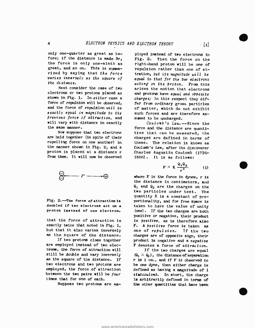
Now suppose that two electrons are held together (in spite of their repelling force on one another) in
the manner shown in Fig. 2, and a
proton is placed at a distance r
from them. It will now be observed
8 r >p
Fig. 2. -The force of attraction is doubled if two electrons act on a
proton instead of one electron.
that the force of attraction is exactly twice that noted in Fig. 1,
but that it also varies inversely as the square of the distance.
If two protons close together are employed instead of two elec- trons, the force of attraction will still be double and vary inversely as the square of the distance. If two electrons and two protons are employed, the force of attraction between the two pairs will be four times that for one of each.
Suppose two protons are em-
AND ELECTRON THEORY [1]
ployed instead of two electrons in Fig. 2. Then the force on the right -hand proton will be one of repulsion rather than one of at- tration, but its magnitude will be
equal to that for the two electrons acting on the proton. From this arises the notion that electrons and protons have equal and opposite charges; in this respect they dif- fer from ordinary gross particles of matter, which do not exhibit such forces and are therefore as- sumed to be uncharged.
Coulomb's Law.- -Since the force and the distance are quanti- ties that can be measured, the charges are defined in terms of these. The relation is known as Coulomb's Law, after its discoverer Charles Augustin Coulomb (1736- 1806). It is as follows:
Q1(42 2
r
where F is the force in dynes, r is
the distance in centimeters, and Q1 and Q2 are the charges on the two particles under test. The quantity K is a constant of pro- portionality, and for free space is taken to have the value of unity (one) . If the two charges are both positive or negative, their product is positive, as is therefore also F. A positive force is taken as one of repulsion. If the two charges are of opposite sign, their product is negative and a negative F denotes a force of attraction.
If the two charges are equal
(Qi = Qz) , the distance of separation r is 1 cm., and if F is observed to be one dyne, then either charge is
defined as having a magnitude of 1 statcoulomb. In short, the charge is arbitrarily defined in terms of the other quantities that have been
F = K (1)
www.americanradiohistory.com

COMPOSITION OF MATTER 5
established in mechanics. The practical unit of charge
is the coulomb, which is equal to
3 x 10⁹ statcoulombs. Hence the statcoulomb is a very small quan-
tity of charge compared to that used in ordinary electrical meas- urements, but the situation is
exactly the same as in ordinary measurements of length, where the
inch or the mile may be employed, depending upon the length to be measured.
The electron and the proton have equal but opposite charges. The magnitude is
e = 4.770 x 10⁻¹° statcoulombs
= 4.770 x 10⁻¹⁰/(3 x 109)
= 1.590 x 10⁻¹⁹ coulombs
All observed charges, positive or negative, are found to be integer
wultifiles of the above value. This
indicates that the electron and proton are the elementary particles
so far as charge is concerned; a
charged body has its charge by virtue of having so many excess electrons or protons in it.
As a simple example of the application of Coulomb's law, let
the force of attraction be calcu- lated between a group of three electrons and a group of four pro - tars, as shown in Fig. 3. The three
electrons have a total charge of
-3 x 4.770 x 10-10 = -14.310 x 10⁻¹⁰
and the four protons have a total charge of
4 x 4.770 x 10-1° = 19.080 x 10⁻¹°
Suppose the separation between the
two groups is 10 -8 cm. Then by Eq. (1) the force is
F = ( -14.31 x 10⁻¹o) (19.08x10 -1 °)
(10 -8) 2
-273 x 10'20
10-16
-273 x 10-4 dynes
Since it is negative, it is a force
of attraction. This may appear to be a very small force, but when
-8 /0 cm.
Fig. 3.- -Force of attraction be- tween three electrons and four
protons.
account is taken of the exceedingly small mass of these charges, the force is enormous in comparison. For example, all bodies attract one another by virtue of another force known as that of gravitation. This is the force that is exerted by the sun on the earth to hold it in its orbit. The gravitational force is in proportion to the mass, and for the tiny masses involved
statcoulombs (negative charge)
in the above problem it would be exceedingly minute. In comparison,
statcoulombs (positive charge)
the above electrical force of
www.americanradiohistory.com

G ELECTRON PHYSICS AND ELECTRON THEORY
-273 X 10-4 dynes is enormous, and
serves to explain why electrical
forces can be employed to produce
large amounts of power in a rela-
tively small space.
1.
Exercises
A group of 3 electrons is sepa- rated by 2.5 X 10 -8 cm. from a
group of 8 electrons. What is
the magnitude and character (repulsion or attraction) of
the force between the two groups?
2. A body has a positive charge of 2 statcoulombs, and is sepa- rated from another body that has a positive charge of 10-3
statcoulombs, by 3/5 cm. What
is the magnitude and character
of the force between the two bodies?
3. Two bodies are separated by 2 cm. A force of 1,000 dynes,
repulsion is desired between them. It is further desired that both bodies have equal
charges. What must be the
magnitude and polarity of the
charges to accomplish this?
Neutrons.- -fin an electron is permitted to approach a proton in such manner that the strong attrac-
tive force does not accelerate it
to a high velocity, the two charges
may merge, whereupon their force effects are tied up in one another
and no external force on any other electrons or protons is ob-
served. The combination therefore
seems to have lost its charge, and
is considered a new particle, and
is called a neutron. The neutron is a particle with
approximately the same mass as the
proton but devoid of any electrical
charge. Whether it actually is a close union of an electron and proton, or is a totally new parti-
cle is not definitely known at the present time; the evidence tends to
indicate that it is a close com- bination as described in the pre- vious paragraph.
The neutron was first discov- ered by Chadwick in 1932, and has, assumed a tremendous importance with the disclosure of the atomic bomb. Its very lack of charge gives it this importance: it is
unaffected by charges such as electrons or protons, and hence can penetrate to the very heart of an atom; i.e., the nucleus, and disrupt the latter. Indeed, it is
only by such effects that a neutron
can be detected, and today its measurement has become of great importance in the regulation of nuclear fission. More will be said of this presently.
Other Particles. ---The other particles mentioned previously are not as yet of practical importance,
although futúre discoveries may completely contradict this state- ment. The positron, discovered by C. D. Anderson in 1932, is a parti-
cle having a positive charge equal
to that of a proton, but having the
mass of an electron. The neutrino is a particle having the mass of an
electron but having no charge. The
mesotron, a negatively charged par-
ticle found in cosmic rays, is be-
tween 100 and 200 times the mass of
an electron, and has a very short life of about one microsecond. More is expected to be learned about it by the use of a Betatron.
TEE ATON. --The preceding dis- cussion has cleared the way for a
www.americanradiohistory.com
COMPOSITION OF MAITIER 7
description of the atom, which is
the smallest particle of any given
element, such as iron, that can
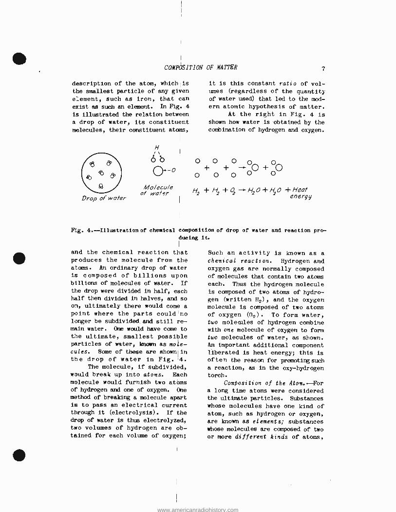
exist as such an element. In Fig. 4
is illustrated the relation between
a drop of water, its constituent molecules, their constituent atoms,
Drop of water
H
óö
Molecule of wofsr
it is this constant ratio of vol- umes (regardless of the quantity of water used) that led to the mod- ern atomic hypothesis of matter.
At the right in Fig. 4 is
shown how water is obtained by the combination of hydrogen and oxygen.
O O O O o + + -> Q + 0
O o o O O
H + H +0 H2O+ 20 +Heat energy
Fig. 4.- Illustration of chemical composition of drop of water and reaction pro- ducing it.
and the chemical reaction that produces the molecule from the atoms. An ordinary drop of water
is composed of billions upon billions of molecules of water. If
the drop were divided in half, each half then divided in halves, and so on, ultimately there would come a point where the parts could no linger be subdivided and still re- main water. One would have come to
the ultimate, smallest possible particles of water, known as mole- cules. Some of these are shown in the drop of water in Fig. 4.
The molecule, if subdivided, would break up into atoms. Each molecule would furnish two atoms of hydrogen and one of oxygen. One
method of breaking a molecule apart
is to pass an electrical current through it (electrolysis). If the
drop of water is thus electrolyzed,
two volumes of hydrogen are ob- tained for each volume of oxygen;
Such an activity is known as a
chemical reaction. Hydrogen and oxygen gas are normally composed of molecules that contain two atoms each. Thus the hydrogen molecule is composed of two atoms of hydro- gen (written H2), and the oxygen molecule is composed of two atoms of oxygen (02). To form water, two molecules of hydrogen combine with one molecule of oxygen to form two molecules of water, as shown. An important additional component liberated is heat energy; this is
often the reason for promoting such a reaction, as in the oxy- hydrogen torch.
Composition of the Aton. --For a long time atoms were considered the ultimate particles. Substances
whose molecules have one kind of atom, such as hydrogen or oxygen, are known as elements; substances whose molecules are composed of two or more different kinds of atoms,
www.americanradiohistory.com

8 ELECTRON PHYSICS AND ELECTRON THEORY
are known as compounds. Water is a compound, so is salt (sodium chloride, NaCI), carbon dioxide 02), etc. Chemistry is concerned
with the interactions of atoms that
produce compounds from elements, break up compounds to form elements,
or cause compounds to react with
one another to produce new com- pounds or elements.
There are over 94 different
elements known, and more are being
added as artificial transmutation
of the atoms of one element into those of another are produced. All
the hundreds of thousands or mil -
lions of possible substances in the
universe are made up of combinations
of the atoms of these elements.
Some of the combinations are simple,
such as water (H20); some are ex-
ceedingly complex, such as the
organic compounds formed of carbon,
together with hydrogen, oxygen, etc. There seems to be no limit to the number of possible combi- nations of atoms which the chemist
can obtain. As an example, consider
the thousands of chemical combi- nations or compounds produced from
coal tar. A few of the diverse products are high -grade perfumes,
beautiful dyes, medicines, and the vast group of plastics. In all these processes, however, the individual atoms remain intact; it
is merely their combinations with one another that are altered.
Shortly before the turn of the
century evidence began to appear that certain atoms, such as radium,
spontaneously disintegrated to form new atoms with the release of an enormous amount of energy. This process was called radioactivity, and caused a revolution in the
concepts of matter. These concepts
are still in the process of re-
vision, but sufficient is known at
this time to furnish a reasonably clear picture of the nature of the
atom. In passing it is of interest
to note that the old dream of the alchemists --to transmute one ele- ment into another- -which was deemed
impossible by the chemists and physicists of the 18th and 19th centuries, has now become a reality,
and new elements, such as plutonium,
have been made from another element,
uranium.
The present -day picture of the atom is that it is made up of an inner core, called the nucleus, surrounded by a number of electrons rotating around the nucleus in
orbits in much the same manner as the planets revolve around the sun. Chemical and ordinary electrical processes have to do with the orbital electrons of the atom; a new branch of engineering called nuclear engineering is appearing on the horizon, and has to do with the nucleus itself.
The Nucleus.- -The nucleus consists of protons and neutrons, bound together by a new force of attraction which at such close quarters overrides the mutually repelling effects between the pro-
tons and causes them and the neu- trons to be bound together very tightly.
Reference to Eq. (1) indicates
that if the distance of separation r between the charges becomes zero,
the coulomb force F becomes in- finite. However, for sub -atomic distances, as in the nucleus, Coulomb's law is not believed to hold; the force F does not increase indefinitely as r decreases, but levels off to a constant value, and a new force of attraction camas
into play. Very little is know
www.americanradiohistory.com
COMPOSITION OF MATTER 9
of this force of attraction, but presumably it falls off very rapidly with distance, possibly inversely as the cube or a higher
power of the distance, so that at
distances greater than that with- in the nucleus, Coulomb's law assumes control and gives rise to the electrical forces normally observed.
The simplest atom of all is that of hydrogen; its nucleus con-
tains but one proton and no neutrons. The nucleus thus has but one positive charge, and there
is one single orbital electron whose negative charge just balances
the nuclear positive charge, there-
by producing an atom of hydrogen that is electrically neutral. The
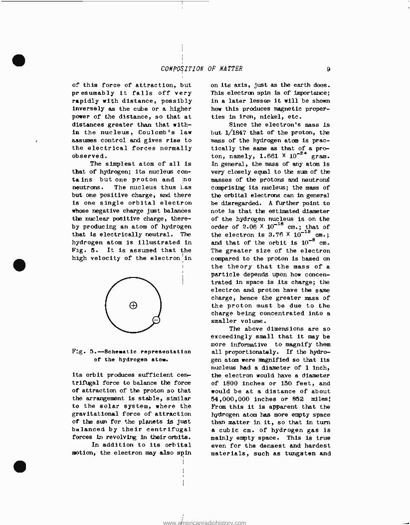
hydrogen atom is illustrated in Fig. 5. It is assumed that the high velocity of the electron in
F g. 5.--Schematic representation of the hydrogen atoo.
its orbit produces sufficient cen-
trifugal force to balance the force
of attraction of the proton so that
the arrangement is stable, similar to the solar system, where the gravitational force of attraction of the sun for the planets is just
balanced by their centrifugal forces in revolving in their orbits.
In addition to its orbital motion, the electron may also spin
on its axis, just as the earth does.
This electron spin is of importance;
in a later lesson it will be shown
how this produces magnetic proper-
ties in iron, nickel, etc.
Since the electron's mass is
but 1/1847 that of the proton, the
mass of the hydrogen atom is prac-
tically the same as that of a pro-
ton, namely, 1.661 X 10 -2' gram.
In general, the mass of any atom is
very closely equal to the sum of the
masses of the protons and neutrong
comprising its nucleus; the mass of
the orbital electrons can in general
be disregarded. A further point to note is that the estimated diameter
of the hydrogen nucleus is on the
order of 2.06 X 10 -18
cm.; that of
the electron is 3.76 X 10 -18
cm.;
and that of the orbit is 10 -8
cm.
The greater size of the electron compared to the proton is based on
the theory that the mass of a particle depends upon how concen- trated in space is its charge; the
electron and proton have the same
charge, hence the greater mass of the proton must be due to the charge being concentrated into a smaller volume.
The above dimensions are so
exceedingly small that it may be more informative to magnify them all proportionately. If the hydro-
gen atom were magnified so that its
nucleus had a diameter of 1 inch,
the electron would have a diameter
of 1800 inches or 150 feet, and would be at a distance of about 54,000,000 inches or 852 miles;
From this it is apparent that the
hydrogen atom has more empty space than matter in it, so that in turn
a cubic cm. of hydrogen gas is
mainly empty space. This is true
even for the densest and hardest materials, such as tungsten and
www.americanradiohistory.com
10 ELECTRON PHYSICS AND ELECTRON THEORY
steel; the hardness of steel is due
to the enormous electrical forces
of attraction between the parts of
the atom and between the various
atoms, rather than to any close
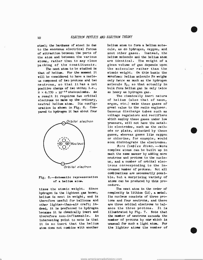
packing of the constituents. The next atom to be studied is
that of helium. For the moment it
will be considered to have a nucle-
us composed of two protons and two
neutrons, so that it has a net
positive charge of two units; i.e.,
2 x 4.770 x 10 -1° statcoulombs. As
a result it requires two orbital
electrons to make up the ordinary,
neutral helium atom. Its config-
uration is shown in Fig. 6. Com-
pared to hydrogen it has about four
Orbital electron
Orbital electron
Fig. 6.-- 8chematic representation
of a helium atom.
times the atomic weight. Since
hydrogen is the lightest gas known,
helium is next in weight, and is
therefore useful for balloons and
other lighter -than -air craft; in-
deed, it is preferred to hydrogen
because it is chemically inert and
therefore non -inflammable. An
interesting point to note is that
it is so inert that the helium
atom does not combine with another
helium atom to form a helium mole-
cule, as do hydrogen, oxygen, and most other gases. Instead, the
helium molecule and the helium atom
are identical. The weight of a
given volume of gas depends upon the molecular rather than the atomic weight. On this basis the
Monatomic helium molecule He weighs only twice as much as the hydrogen molecule H2, so that actually in bulk form helium gam is only twice
as heavy as hydrogen gas. The chemically inert nature
of helium (also that of neon, argon, etc.) make these gases of great value to the radio engineer.
Gaseous discharge tubes such as voltage regulators and rectifiers which employ these gases under low
pressure, will not have the metal-
lic electrodes, such as the cath-
ode or plate, attacked by these gases, whereas gases like oxygen or chlorine, for example, would soon disintegrate the electrodes.
Nore Complex Atoms.- -More complex atoms can be built up in
much the same manner by adding more neutrons and protons to the nucle-
us, and a number of orbital elec- trons corresponding to the in-
creased number of protons. Not all
combinations are necessarily possi-
ble, but a surprising variety of atoms can be produced by this pro- cedure.
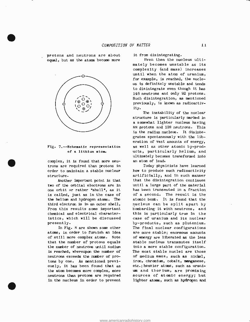
The next atom in the order of
complexity is lithium (Li), a metal.
Its nucleus consists of three pro-
tons and four neutrons, and there are three orbital electrons to bal-
ance the three protons. It is
illustrated by Fig. 7. Note that
the number of neutrons exceeds the
number of protons by one' which is unusual for such a light atan. For
the lighter atoms the number of
www.americanradiohistory.com
COXPOSITION OF NATTER 11
protons and neutrons are about equal, but as the atoms become more
Fig. 7.-- Schematic representation
of a lithium atom.
complex, it is found that more neu-
trons are required than protons in
order to maintain a stable nuclear
structure.
Another important point is that
two of the orbital electrons are in
one orbit or rather "shell ", as it
is called, just as in the case of the helium and hydrogen atoms. The
third electron is in an outer shell,
From this results some important chemical and electrical character-
istics, which will be discussed presently.
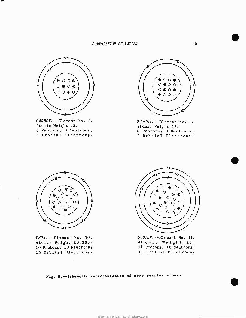
In Fig. R are shown some other
atoms, in order to furnish an idea
of still more complex atoms. Note
that the number of protons equals
the number of neutrons until sodium
is reached, whereupon the number of
neutrons exceeds the number of pro-
tons by one. As mentioned previ- ously, it has been found that as
the atom becomes more complex, more
neutrons than protons are required
in the nucleus in order to prevent
it from disintegrating.
Even then the nucleus ulti- mately becomes unstable as its
complexity (and mass) increases until when the atom of uranium, for example, is reached, the nucle-
us is definitely unstable and tends
to disintegrate even though it has
146 neutrons and only 92 protons.
Such disintegration, as mentioned
previously, is known as radioactiv-
ity.
The instability of the nuclear
structure is particularly marked in
a somewhat lighter nucleus having
88 protons and 138 neutrons. This
is the radium nucleus. It disinte-
grates spontaneously with the lib-
eration of vast amounts of energy,
as well as other atomic by -prod- ucts, particularly helium, and ultimately becomes transformed into
an atom of lead.
Today physicists have learned
how to produce such radioactivity
artificially, and in such manner that the disintegration continues until a large part of the material has been transmuted in a fraction of a second. The result is the
atomic bomb. It is found that the nucleus can be split apart by bombarding it with neutrons, and this is particularly true in the case of uranium and its nuclear by- products, such as plutonium. The final nuclear configurations are more stable; enormous amounts
of energy are liberated as the less
stable nucleus transmutes itself into a more stable configuration.
The most stable nuclei are those of medium mass, such as nickel,
iron, chromium, cobalt, manganese,
etc.; heavier atoms, such as urani-
um and thorium, are promising sources of atomic energy; but lighter atoms, such as hydrogen and
www.americanradiohistory.com
COMPOSITION OF NATTER
CARBON. -- Element No. 6.
Atomic Weight 12.
6 Protons, 6 Neutrons, 6 Orbital Electrons.
NEON, -Element No. 10.
Atomic Weight 20.183. 10 Protons, 10 Neutrons,
10 Orbital Electrons.
12
OXYGEN.--Element No. 8.
Atomic Weight 16.
8 Protons, 8 Neutrons, 8 Orbital Electrons.
SODIUM.- Element No. 11. At omic Weight 23. 11 Protons, 12 Neutrons, 11 Orbital Electrons.
Fig. 8.-- Schematic representation of more complex atome.
www.americanradiohistory.com

COMPOSITION OF MATTER 13
helium can liberate energy as they
combine to form the more stable medium -weight atoms. So far no
practical method has been devised
to bring this about. If this can
be accomplished, the cost of atomic
energy will probably decrease mark-
edly, as the lighter atoms are far
more abundant on this earth than
the heavier atoms such as uranium.
CHEMICAL REACTIONS. --It was
stated previously that chemical reactions depend upon interactions
between the orbital electrons of
the various atoms. For example,
in the case of water, the two or-
bital electrons of the two hydro-
gen atoms become more or less asso-
ciated with the oxygen atom, and
fill out its outer, second shell,
so that the latter now contains
8 instead of six electrons.
From a charge viewpoint the
oxygen atom has now two excess negative charges, and the two hy-
drogen atoms now have each a posi-
tive charge (that due to the pro-
ton remaining). The two hydrogen
atoms are therefore attracted to the oxygen atom by Coulomb's law,
and thus form the very stable (tightly bound) water molecule H20. The reason why the oxygen
atom can extract two electrons from the hydrogen atom appears to be due tp a peculiarity of the
atomic structure: each shell is
most stable and saturated when it
has a certain number of electrons
in it.
The first shell nearest the
nucleus is saturated when it has two electrons in it. It then has
no tendency to take electrons from
other atoms, and so becomes chemi-
cally inert. Reference is made to
the helium atom which has this structure. On the other hand, if
the first shell has but one elec-
tron, as in the case of hydrogen,
it may take up a second electron from some other atom such as potas-
sium, so as to form potassium hy- dride, but the tendency is generally
in the reverse direction: it tends
to give up its electron to an ele-
ment like oxygen.
In the case of the second shell,
saturation occurs when it has 8
electrons. The element lithium, that has but one electron in the
second shell, does not show any tendency to acquire 7 additional orbital electrons for this shell,
but instead acts like hydrogen, and
tends to give up its electron to
an atom like oxygen. Since each
lithium atom has but one electron
in its outer shell, and oxygen de-
sires two electrons to complete its
outer shell, two atoms of lithium
must combine with one of oxygen to
form lithium oxide, L120, just as
in the case of hydrogen, H20. Valence. --In the case of
copper, there are two electrons in
the outer shell, so that copper can
give up one or two electrons, as
required. Thus if copper is heated
in conjunction with a limited amount of oxygen, it gives up one
electron to each oxygen atom., forming cuprous oxide, Cu20 (Cu is
the chemical symbol for copper). Note that this enables the maxi- mum number of copper at to com-
bine with the limited number of
oxygen atoms. On the other hand, if the
number of copper atoms is limited
relative to the oxygen atoms, then
each copper atan gives up both elec-
trons to each oxygen atom, forming
cupric oxide Cu O. In the first
case, copper is said to have a posi- tive valence of one; i.e., it gives
www.americanradiohistory.com
14 ELECTRON PHYSICS
up one orbital electron in reacting
with a suitable other atom to form a compound. In giving up this elec-
tron, it becomes itself positive and adheres to the atom which it has
made correspondingly negative by bestowing an electron on it.
Lithium and hydrogen have positive valences of one.
In the case of cupric oxide,
copper has a positive valence of two, because it has given up two electrons to the oxygen atom. On
the other hand, oxygen has a nega- tive valence of two, because it has
taken on two (negative) electrons.
For same reason not known directly, oxygen generally has a negative valence of two, but at least one compound is known in which its val-
ence is one, namely, hydrogen peroxide, H202. (It will be re-
called that this was used as a
propellant for the buzz bombs.) Sometimes an element can have
either a positive or negative valence. Phosphorous. for example,
can have a negative valence of 3
and a positive valence of 5. In
the first case it takes on 3 elec-
trons in addition to the 5 present
in the outer shell, to make up the
total of 8 required for saturation.
By taking on 3 electrons from other
atoms willing to furnish them, it
acquires a negative charge of 3 units; it therefore has a negative
valence of three. On the other hand, phosphorous can also be in- duced to yield the five electrons
in its outer shell to atoms, such as of oxygen, that have a suffi- cieñtly strong affinity (desire)
for the electrons. In doing so, the phosphorous acquires a positive
charge of 5 units; it has a posi- tive valence of five. In general,
atoms whose outer shell are about
AND ELECTRON THEORY
half full exhibit such dual valence. Atomic Number. -Chemical re-
actions therefore involve the electrons of the outermost shell only. The first shell is saturated
when it has two electrons, as in
the case of helium; such an atom is chemically inert, The second shell is saturated when it has eight electrons as in the Case of neon, another inert gas. Beyond the second shell the conditions for
saturation become more involved, but it is unnecessary for the pur- pose of this assignment to pursue this phase of the subject any further.
Instead, it is of interest to note that the number of orbital electrons just equals the number of
protons in the nucleus in the case
of a normal, neutral atom. This number is known as the atomic number. It is more definitely associated with the number of pro- tons in the nucleus. The reason is
that it is possible to remove (at
least temporarily) one or more orbital electrons by a process known as ionization, but until recently, no means were known for changing the number of protons in
the nucleus.
In the accompanying table of Atomic Weights, the names, symbols,
atomic numbers, and atomic weights of the various chemical elements
are given. Observe that in the
case of hydrogen, the atomic number
and weight are practically unity, whereas for the other elements the
atomic weight is the greater. This
follows at once from the fact that
the nucleus contains neutrons. as
well as protons (except in the case
of hydrogen); the neutrons add to
the weight, but being uncharged, require no corresponding orbital
www.americanradiohistory.com

e
e
COMPOSITION OF NATTER 15
ATOMIC WEIGHTS`
NAME
SYM-
BOL
ATOMIC
NO.
ATOMIC
WEIGHT NAME
SYM-
BOL
ATOMIC
NO.
ATOMIC
WEIGHT
Actinium Ac 89 (227) Mercury Hg 80 200.61
Alabamine Ab 85 (221) Molybdenum Mo 42 96.0
Aluminum Al 13 26.97 Neodymium Nd 60 44.27
Americum .. 95 Neon Ne 10 20.183
Antimony Sb 51 121.76 Neptumium Np 93 (239)
Argon A 18 39.944 Nickel Ni 28 58.6P
Arsenic As 33 74.93 Nitrogen N 7 14.008
Barium Ba 56 137.36 Osmium Os 76 190.8
Beryllium Be 4 9.02 Oxygen 0 8 16.000
Bismuth Bi 83 209.00 Palladium Pd 46 106.7
Boron B 5 10.82 Phosphorus P 15 31.02
Bromine Br 35 79.916 Platinum Pt 78 195.23
Cadmium Cd 48 112.41 Plutonium Pn 94 (239)
Calcium Ca 20 40.08 Polonium' Po 84 (210)
Carbon C 6 12.00 Potassium X 19 39.10
Cerium Ce 58 140.13 Praseodymium Pr 59 140.92
Caesium Cs 55 132.81 Protoactinium Pa 91
Chlorine CI 17 35.457 Radium Ra 88 225.97
Chromium Cr 24 52 01 Radon Rn 86 222
Cobalt Co 27 58.94 Rhenium Re 75 186.31
Columbium Cb 41 93.3 Rhodium Rh 45 102.91
Copper Cu 29 63.57 Rubidium Rb 37 b5.44
Curium .. 96 Ruthenium Ru 44 101.7
Dysprosium Dy 66 162.46 Samarium Sm, Sa 62 150.43
Erbium Er 68 167.64 Scandium Sc 21 45.10
Europium Eu 63 152.0 Selenium Se 34 79.2
Fluorine F 9 19.00 Silicon Si 14 28.06
Gadolinium Gd 64 157.3 Silver Ag 47 107.880
Gallium Ga 31 69.72 Sodium Na II 22.997
Germanium Ge 32 72.60 Strontium Sr 38 87.63
Gold Au 79 197.2 Sulfur S 16 32.06
Hafnium Hf 72 178.6 Tantalum Ta 73 181.4
Helium He 2 4.002 Tellurium Te 52 127.5
Holmium Ho 67 163.5 Terbium Tb 65 159.2
Hydrogen H I 1.0078 Thallium TI 81 204.39
Illinium II 61 (146) Thorium Th 90 232.12
Indium In 49 114.8 Thulium Tm 69 169.4
Iodine I 53 126.92 Tin Sn 50 118.70
Iridium Ir 77 193.1 Titanium Ti Z2 47.90
Iron Fe 26 55.84 Tungsten W 74 184.0
Krypton Kr 36 83.7 Uranium U 92 238.17
Lanthanum La 57 138.92 Vanadium V 23 50.95
Lead Pb 82 207.22 Virginium Vi 87 (224)
Lithium Li 3 6.940 Xenon Xe 54 131.3
Lutecium Lu 71 175.0 Ytterbium Yb 70 173.3
Magnesium Mg 12 24.32 Yttrium Y 39 88.92
Manganese Mn 25 54.93 Zinc Zn 30 65.38
Masurium Ma 43 Zirconium Zr 40 91.22
'Values in parentheses are approximate only and have not been adopted
by the Committee on Atomic weignts.
www.americanradiohistory.com

16 ELECTRON PHYSICS AND ELECTRON THEORY
electrons to balance.
Hence, to sum up, the atomic
number is a measure of the number
of protons in the nucleus, and
therefore of the number of orbital
electrons in the case of a neutral
atom (one that is not ionized) . If
the atomic number is known then, by
the rules of atom construction, it
is possible to calculate the number
of electrons in each shell, and thus
finally the number of electrons in
the outermost shell. Once the
latter fact is known, a very good
idea of chemical (and even of the
electrical and heat properties) of
the atom can be predicted.
ISOTOPES AND ISOBARS.--An in-
spection of the table on atomic
weights reveals that the atomic
numbers are integers (whole num-
bers), but that the atomic weights
are not. By specifying the atomic
weight of oxygen as 16, most of the
other atoms have weights that are
more nearly whole numbers, but
still there are appreciable dis-
crepancies. Hydrogen, for example,
has a relative atomic weight of
1.0078 instead of exactly one, and
zinc has an atomic weight of 65.38.
This seems to contradict the
idea that all atoms are built up of
neutrons and protons, for then all
elements should be integral multi-
ples of hydrogen (having one proton)
in weight. The discrepancy is
found to be due to two factors, of
which the most important is that of
mixtures of two isotopes of the
given element. Isotopes.--An isotope is an
element that has the same atomic
number and hence the same chemical
properties as another element, but
has a different mass. The reason
is relatively simple. Tale the case
of hydrogen: its nucleus consists
of one proton; its atomic weight is
one, and it therefore has one or-
bital electron and a positive valence of one. Suppose a neutron
is added to the nucleus. The
atomic weight is now two instead of
one, but the atomic number is still
one, and the new atom, calléd deu-
terium (heavy hydrogen), has also
only one orbital electron and a positive valence of one.
Deuterium is an isotope of hydrogen. They are chemically in-
distinguishable, and are present in
nature in the ratio of about 8
parts of deuterium to 1,000 parts of
hydrogen. Consequently ordinary hydrogen gas does not have an atomic weight of one as measured,
nor of two, but has an average weight of 1.0078. The same is true
of practically all the other ele- ments; the presence of isotopes makes the average atomic weight as
measured come out other than an integer multiple of any one atomic
weight chosen as a reference, such
as that of oxygen. In passing it
is to be noted that heavy water contains deuterium instead of hydrogen.
An isotope that has come into
prominence is that of uranium 235.
Ordinary uranium has an atomic weight of 238. If three neutrons
are removed from the nucleus, the
atomic weight drops to 235. The new element uranium 235 has the same chemical properties as uranium
238, but the nuclear structure is
unstable and can be split by neutron
bombardment into new atoms of lower
atomic weight. Under the proper conditions this occurs with ex- plosive force.
Another isotope of interest is
that of helium. It will be recalled
that ordinary helium, as extracted
www.americanradiohistory.com

COMPOSITION OF NATTER 17
from natural gas, has an atomic weight of four. It has a nucleus
composed of two neutrons and two
protons; its atomic number is
therefore two. Certain so- called
alpha particles, positively charged
and ejected by radium, have also
been identified as helium atoms. However, the nuclei in these parti-
cles consist of but one neutron and
two protons. The atomic number is
still two, but the atomic weight is
only three. Thus the alpha parti-
cle has the same atomic number and
hence chemical properties (mainly
that of being inert) as the ordi-
nary helium atom; it is therefore
an isotope of the latter.
Isobars. -An isobar is an atom that has the same atomic weight as
another atom, but has a different
atomic number, and hence different chemical properties. In short, its
nucleus has the same sum of protons
and neutrons as the other nucleus,
but the division of the sum into
protons and neutrons is different.
At present there are not many
isobars known, nor do they appear to have any great practical im- portance. It is necessary to point
out in connection with isobars and
isotopes that one cannot remove or
add protons or neutrons to a given
nucleus at will; only certain combinations are permitted by nature, and of these only certain combina-
tions are relatively stable. How-
ever, even within this limitation,
a large number of new atoms have been artificially produced in the laboratory that have not been found in nature, and as a result mankind is now entering a new ers. in physi- cal science and industry.
MATTER AND ENERGY.--Up until
about 1905 two separate principles
were recognized:
1. The law of the Conserva-
tion of Matter, and
2. The law of the Conserva-
tion of Energy.
The first law stated that matter can neither be created nor destroyed; it can only be trans-
formed from one kind of matter to
another kind.
The second law stated that energy can neither be created nor
destroyed; it can only be trans- formed from one kind to another, such as electrical energy into heat
energy, etc.
Einstein's Law.- -From the study of high speed electrons, whose mass increases indefinitely
as their velocity approaches that
of light, and from other-considera-
tions, Einstein enunciated a famous
law in 1905 that energy can be con-
verted into mass, and mass into energy. His law is in itself a very simple expression:
M = W/c2 (2)
Where M is the mass in grams, W is the energy in ergs that is equiva-
lent to M, and c is the velocity of light, 3 X 1010 cm. /sec. For ex-
ample, if a body has an amount of energy, such as kinetic energly owing to its velocity, of say 10 ergs, then its mass is increased by an amount
M= 101E /(3 X 1010)2 = 101e 1020
11.11 X 10- a grams
= 11.11 X 10s milligrams
The amount of increase in mass
isvery small even for considerable
amounts of energy, owing to the
www.americanradiohistory.com
18 ELECTRON PHYSICS AND
factor c2 that occurs in Eq. (2).
Nevertheless, the fact that one
can be converted into the other
and vice -versa leads to a com-
bined law of conservation; namely,
that the sun total of the mass and
energy of a system is constant, and
cannot be created nor destroyed.
But mass may be converted into
energy, and energy into mass; the
proportions are given by Eq. (2)
above.
It is not the purpose of this
technical assignment to go into an
extended discussion of nuclear
physics, since this would require
very advanced mathematics and more-
over would not be directly perti-
nent to radio engineering. How-
ever, the implications of Eq. (2)
are so vast as to justify a brief
discussion of this principle here.
It may appear puzzling to many
how matter presumably can be con-
verted into energy and energy into
matter, since energy in general
implies matter in motion, and it
appears absurd to say that matter
can be converted into motion, for
the latter is an attribute or
property of the former. However,
Eq. (2) does not actually say this;
Eq. (2) merely states that one
bro$erty of matter, namely its mass,
can be converted into anot:.er property, its energy.
What the ultimate nature of
matter is may never be known; one
can only be aware of it through its
effects on the five senses. Any
substance is recognized by virtue
of its inertia: the effect is
measured in terms of a quantity
called mass. It is the gravitation-
al pull of the earth upon the mass
of a substance that gives the
substance weight and produces a
corresponding pressure on the hand
ELECTRON THEORY
supporting the substance. It is
the same characteristic of mass that
causes an automobile to coast after
the clutch is released.
In the past the mass of an object was assumed to be constant
regardless of the velocity of the object, slid the kinetic energy of the moving object was expressed as
K.E. = (1/2)mv4 (3)
where m is the mass (assumed con-
stant) and v is the velocity. Ex-
periments with very high -speed electrons, such as in television projection picture tubes and X-ray tubes, indicate that when the elec-
tron moves with a velocity compara-
ble to that of light, its mass be- comes very much greater than '.ts
rest -mass (stationary mass). This was an unexpected result,
and was ultimately explained by Einstein by his special relativity theory. The law given in Eq. (2)
is a consequence of this theory and
of a study of the phenomena in- volved in radiation. What happens
is that at high velocities, the
energy of the particle is in part
associated with its velocity and in
part associated with its increase in
mass; no additional matter has pre-
sumably been created, only a funda-
mental property of the original substance, namely its mass, has
been increased. Atomic Ene rgy. -- Einstein's law
has the following significance with respect to the atom. It was men- tioned that the atomic weight of various elements are not integer
multiples of hydrogen. The main reason given was that actual meas-
urements were made on mixtures of
isotopes of the given element, so that the average weight measured
www.americanradiohistory.com
COMPOSITION OF MATTER 19
was different from that of any one
isotope itself. Even in the case of
a single isotope, its mass differs
from the sum of the masses of its
constituent protons and neutrons. The
difference, if a deficit, represents
energy liberated by the formation of
the element; if an excess, it repre-
sents energy put into the element
in its formation.
Elements below silver in weight
absorb protons or neutrons or both to
form heavier elements that are slight-
ly deficient in mass. Thus the pro-
cess of fusion liberates energy. Ele-
ments above silver in weight absorb
protons and neutrons to form heavier
elements slightly excessive in weight.
Here fusion absorbs energy. If the
heavier element decomposes into light-
er elements (fission) the above ener-
gy is liberated once more.
The sun and stars furnish ener-
gy by fusion. On the earth, the only
known source of atomic energy is that
of fission; specifically that of U235
and plutonium (possibly thorium) into
lighter elements. Although the ener-
gy liberated is but a fraction of
that theoretically available, a.rela-
tively small atomic bomb liberates as
much energy as that of 20,000 tons of
TNT! The reason why silver plays a
central role is owing to the short -
range attractive forces and longer
range Coulomb repelling forces men-
tioned previously. or lig Tei
of small dlméris3óns the short range
¡ attractive forces predominate and
promote fusion with the release of
energy. For heavy nuclei of large di-
mensions the Coulomb forces predomi-
nate and promote fission with the re-
lease of energy. In silver the two
types of forces about balance so that
neither fusion nor fission tends to
occur. --
Normally, nuclei are in a semi-
stable or met- le state, and a
certain amount of activation energy
is required to start the reaction of
fusion or fission as the case may be.
The amount of energy liberated
can be calculated from Einstein's law:
multiply through Eq. (2) by C2; and ob-
tab: W = Mc 2 (4)
where M is the loss in mass, and W
is the energy thereby liberated.
Heat Energy. -One of the most important forms of energy is heat en-
ergy. It represents the sum of the
kinetic energies of the atoms, mole-
cules, and free electrons in a sub-
stance. Thus warmth, the sensation
conveyed to the brain, is really due
to a helter -skelter dashing about of
the particles in the substance touch-
ed. The hotter the substance (the
higher the temperature) the more fu-
riously do these particles dash about
or vibrate, and the greater is the
total kinetic energy in the substance.
It may be argued that a moving
car has a sum total of kinetic ener-
gy equal to that of all its molecules,
atoms and electrons yet ma.y be cool
to the touch. The answer is the mo-
tion of all parts of the car is co-
ordinated (in one direction) whereas
in the case of heat energy, the motion
of the various particles comprising
the car are uncoordinated: one mole-
cule may move a small distance one way
while another moves in another direc-
tion. Such random motion of the par-
tidles represents heat or thermal en- fj
ergy; the car as a unit does not move.
When a body is heated by contact
with a hotter body, such as a flame,
the faster moving particles of the
flame speed up the slower moving par-
ticles of the cooler body, whereupon
its heat energy and temperature begin
to increase. I#' the body is a solid,
its molescules, etc. begin to vibrate
www.americanradiohistory.com

20 ELECTRON PHYSICS
faster and faster, but still main-
tain their average positions, so
that the body still remains a
solid. As the temperature goes up,
the vibrations become so intense
that the forces of attraction be-
tween the molecules are broken
down, and the body melts, becoming
a liquid. The molecular forces are
still sufficient to prevent the
molecules from flying apart and
increasing the volume of the body,
but they are no longer able to main-
tain their shape of the body, and
it therefore assumes the shape of
the containing vessel. This is
characteristic of a liquid.
As the temperature is still
further increased, the vibrations
become so intense that the mole-
cules can no longer hold together,
and they fly apart. The liquid is
now said to vaporize and become a
gas. The volume now becomes that
of the vessel completely enclosing
the gas, otherwise the latter will
tend to expand indefinitely. More will be said about heat
energy in relation to thermionic
emission and the like, but the
above brief description affords a
satisfactorily clear picture of the
basic phenomenon.
APPLICATIONS TO RADIO ENGINEERING
FREE ELECTRONS.- -Radio engi-
neering, like chemistry, is mainly
concerned with the behavior of the
orbital electrons, particularly those in the outermost orbit (the
"valence" electrons). In certain
substances these electrons become
detached from their atoms and wander about more or less freely inside of the substance. They are
AND ELECTRON THEORY
then known as free electrons, and
they can be caused to drift through
the substance, whereupon they con-
stitute an electric current flow.
The substance is then said to have
electrical conductivity.
Under certain conditions of
heating, the free electrons can be
"boiled out" of the material into
free space; this is known as therm -
ionic emission, and is the funda-
mental basis of vacuum tube action.
In the case of certain substances,
light is capable of causing elec-
tron emission; this is known as
bhotoelectric emission, and is the
fundamental basis of operation of
phototubes. Since these effects
are of such great importance to electrical engineering in general,
and radio engineering in particular,
it is clear that a more detailed
discussion is in order.
Metals. -It was shown previ- ously that certain atoms have but
one, two, or three electrons in
the outermost orbit, and that such
atoms have a tendency to give these
electrons to another kind of atom whose outermost orbit is nearly saturated, rather than to take on
sufficient electrons to saturate their own outermost orbits. In
short, the rule appears to be that
if the outermost orbit has few
electrons and is far from being
saturated, the atom during a chemi-
cal reaction g-ives away the few electrons; if the outermost orbit
is almost saturated, the atom during a chemical reaction takes on
sufficient electrons to saturate
the orbit. Atoms that give away electrons
become positively charged in the process, and are known as electro-
positive elements. In general metals have this characteristic.
www.americanradiohistory.com

APPLICATIONS TO RADIO ENGINEERING 21
Atoms that take on electrons be- come negatively charged as a re- sult, and are called electronegative elements. Examples of these are oxygen, chlorine, fluorine, etc. Many atoms have a large, but not too large, number of electrons in their
outermost orbits; these may be considered as either electropositive
or electronegative. Two examples of this type are carbon and sulphur.
The metals are normally elec- tropositive. The ease with which they give up electrons depends upon their atomic structure. If there is but one electron in the outer - most orbit, the metal loses this electron more readily than if there are two or three. If the outer- most orbit is at a considerable distande from the nucleus; i.e.,
if there are many intervening orbits, then if the atom has but one electron in this orbit, it can release this electron more readily than an atom that has but few or- bits and one electron in the outer- most orbit.
For example, from Fig. 7 it is
clear that lithium has two orbits, with a single electron in the sec- ond orbit. This electron can be given up with moderate ease. From Fig. 8 it is seen that sodium has three orbits, with a single elec- tron in the third orbit. The sodi- um atom can yield its electron more readily than can lithium. Potassi- um has four orbits, with a single electron in its fourth orbit. Ru- bidium has five orbits, with a single electron in its fifth orbit, and caesium has six orbits, with a single electron in its sixth orbit. From the rule given above it follows that the caesium atom will give up its outermost orbital elec-
tron most readily, and is therefore most electropositive; rubidium comes next, followed by potassium, sodium, and lithium, and finally hydrogen, which has one and only one electron and orbit.
Crystalline Structure of Solids. -- Mention was made that atoms
combine to form molecules; a mole- cule of hydrogen contains two hy- drogen atoms, (H2), and a molecule of water contains two atoms of hydrogen and one of oxygen (H20) .
It is found, however, that in the
case of a true solid, the molecular
configuration ceases to have sign- ificance, and is replaced by the crystal. The crystal is an orderly arrangement of the atoms, that can be expanded indefinitely so as to
form crystals of any size. For example, ordinary salt consists of
equal numbers of sodium and chlo- rine atoms. Fused salt (liquid form) probably consists of individ-
ual molecules, each composed of one atom of sodium and one atom of chlorine (NaCl) .
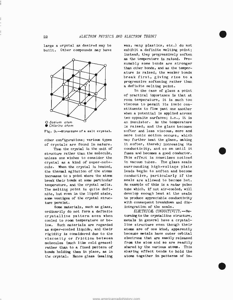
Solid salt, however, consists of orderly rows of sodium and chlorine atoms, arranged in alter- nating sheets or planes. The ar- rangement is shown in Fig. 9. Ob- serve how each atom of one kind, such as sodium (Na), is surrounded by atoms of the other kind, chlo- rine (C1). The lines between the atoms represent the coulomb forces of attraction between opposite charges; the chlorine atom being negative and the sodium atom being positive, because the sodium atom gave up its outer orbital electron to the chlorine atom. It is ap- parent from the figure that this pattern, cubical in form, can be continued indefinitely in all directions, so that as small or as
www.americanradiohistory.com
22 CLECTRON PHYSICS AND ELECTRON THEORY
large a crystal as desired may be
built. Other compounds may have
O Sodium atom Chlorine atom
Fig. 9.-- Structure of a salt crystal.
other configurations; various types
of crystals are found in nature.
Thus the crystal is the unit of
structure rather than the molecule,
unless one wishes to consider the
crystal as a kind of super -mole-
cule. When the crystal is heated,
the thermal agitation of the atoms
increases to a point where the atoms
break their bonds at some particular
temperature, and the crystal melts.
The melting point is quite defi-
nite, but even in the liquid state,
some vestiges of the crystal struc-
ture persist.
Some materials, such as glass,
ordinarily do not form a definite
crystalline pattern even when cooled to room temperature or be-
low. Such materials are regarded
as super -cooled liquids, and their
rigidity is considered due to the
viscosity or friction between molecules (much like cold grease)
rather than to a fixed pattern of
bonds holding them in place, as in
the crystal. Hence glass (sealing
wax, many plastics, etc.) do not
exhibit a definite melting point;
instead, they progressively soften as the temperature is raised. Pre-
sumably some bonds are stronger than other bonds, and as the temper-
ature is raised, the weaker bonds
break first, giving rise to a
progressive softening rather than
a definite melting point.
In the case of glass a point of practical importance is that at
room temperature, it is much too viscous to permit its ionic con- stituents to flow past one another
when a potential is applied across two opposite surfaces; i.e., it is
an insulator. As the temperature Is raised, and the glass becomes softer and less viscous, more and more ionic motion occurs, which may further heat the glass, making
it softer, therebi increasing its
conductivity, and so on until it
fuses and becomes a good conductor. This effect is sometimes noticed in vacuum tubes. The glass seals
surrounding high- voltage plate leads begin to soften and become conductive, particularly if the
seals are allowed to become hot. An example of this is a radar pulse
tube which, if not air -cooled, will
develop enough heat at the seals
to produce appreciable conductivity with consequent breakdown and dis- integration of the seals.
ELECTRICAL CONDUCTIVITY.--Re-
turning to the crystalline structure,
metals in general have a crystal- line structure even though their atoms are of one kind, apparently because metals have outer orbital electrons that are easily released
from the atom and so are readily shared by the various atoms. This
sharing effect tends to hold the
atoms together in patterns of in-
www.americanradiohistory.com
e APPLICATIONS TO RADIO ENGINEERING 23
definite size; i.e., in crystalline
configuration. In actual practice
large crystals are rare because any
sudden change in temperature or
pressure may result in deforming or
breaking up the crystal into smaller
crystals. As a result most large
objects are really made up of a
large number of tiny crystals inter-
laced and held together thereby,
perhaps in the same way that the
fibers of paper or felt are matted
together. Nevertheless large
crystals of copper, for example,
have been produced by exercising
care in growing the crystal from
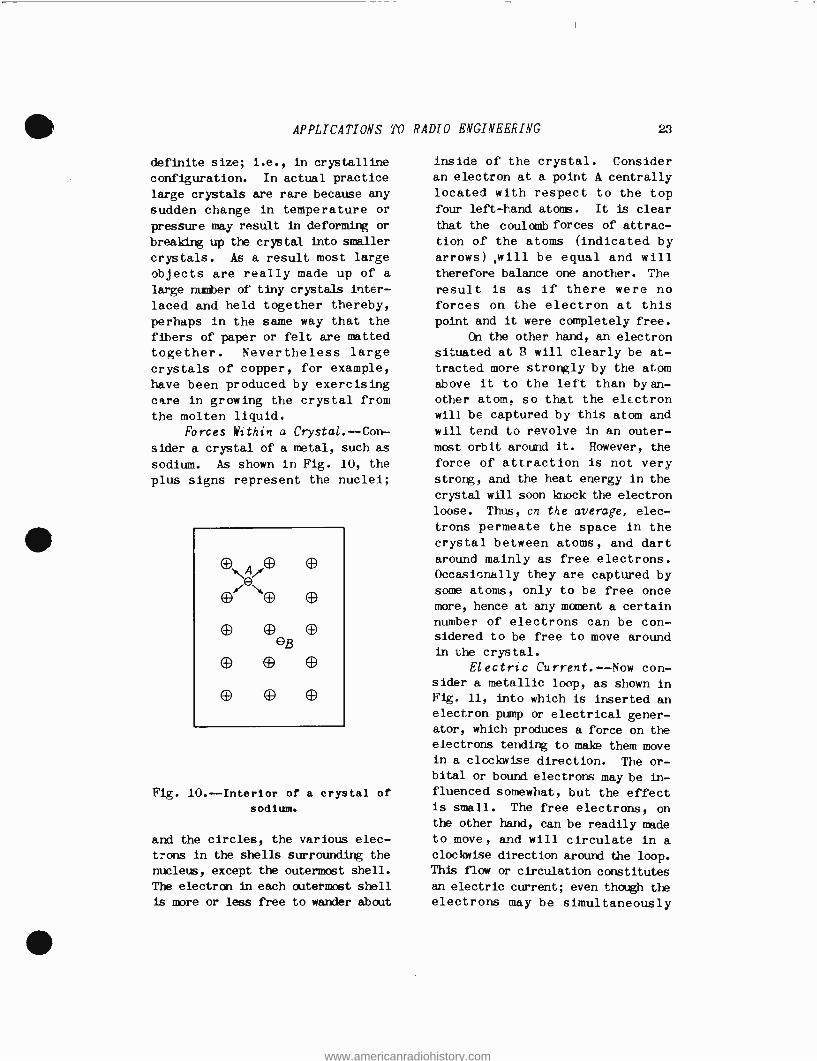
the molten liquid. Forces Within a Crystal. --Con-
sider a crystal of a metal, such as
sodium. As shown in Fig. 10, the
plus signs represent the nuclei;
O O
Fig. 10.-- Interior of a crystal of
sodium.
and the circles, the various elec-
trons in the shells surrounding the
nucleus, except the outermost shell.
The electron in each outermost shell
is more or less free to wander about
inside of the crystal. Consider an electron at a point A centrally
located with respect to the top
four left -rand atoms. It is clear
that the coulomb forces of attrac-
tion of the atoms (indicated by arrows) .will be equal and will therefore balance one another. The
result is as if there were no
forces on the electron at this
point and it were completely free.
On the other hand, an electron
situated at B will clearly be at-
tracted more strongly by the atom above it to the left than by an-
other atom, so that the electron
will be captured by this atom and
will tend to revolve in an outer-
most orbit around it. However, the
force of attraction is not very strong, and the heat energy in the
crystal will soon ]mock the electron
loose. Thus, cn the average, elec-
trons permeate the space in the
crystal between atoms, and dart
around mainly as free electrons. Occasionally they are captured by
some atoms, only to be free once
more, hence at any moment a certain
number of electrons can be con- sidered to be free to move around
in the crystal.
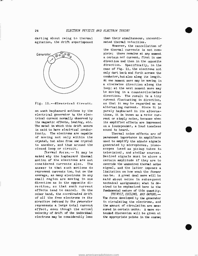
Electric Current.- -Now con- sider a metallic loop, as shown in Fig. 11, into which is inserted an electron pump or electrical gener- ator, which produces a force on the electrons tending to make them move in a clockwise direction. The or- bital or bound electrons may be in- fluenced somewhat, but the effect is small. The free electrons, on the other hand, can be readily made to move, and will circulate in a
clockwise direction around the loop. This flow or circulation constitutes
an electric current; even though the electrons may be simultaneously
www.americanradiohistory.com
24 ELECTRON PHYSICS AND ELECTRON THEORY
darting about owing to thermal agitation, the drift superimposed
Fig. 11. -- Electrical Circuit.
on such haphazard motions by the electrical generator is the elec-
trical current normally observed by its magnetic effects, heating, etc.
The metal in which this drift occurs
is said to have electrical conduc-
tivity. The electrons are capable
of moving not only within the
crystal, but also from one crystal
to another, and thus around the closed loop or circuit.
Thermal Noise.-- It may be asked why the haphazard thermal
motion of the electrons are not considered currents also. The
answer is that such motions do represent currents too, but on the
average, as many electrons in any
small region are moving in one direction as in the opposite di- rection, so that such current effects tend to cancel. On the
other hand, the coordinated drift
of all the free electrons in the
direction imbosed by the generator
represents a large total current
effect, even though the actual velocity of drift of the individual
electrons may be considerably less
than their simultaneous, uncoordi- nated thermal velocities.
However, the cancellation of the thermal currents is not com- plete; there remains at any moment
a certain net current, first in one
direction and then in the opposite direction. Specifically, in the
case of Fig. 11, the electrons not only dart back and forth across the conductor, but also along its length.
At one moment more may be moving in
a clockwise direction along the loop; at the next moment more may be moving in a counterclockwise direction. The result is a tiny current fluctuating in direction, so that it may be regarded as an alternating current. Since it is
purely haphazard in its alterna- tions, it is known as a noise cur- rent or simply noise, because when its amplified effects are impressed
on a loudspeaker, a loud toneless sound is heard.
Thermal noise effects are of paramount importance in amplifiers used to amplify the minute signals generated by microphones, icono- scopes (used as pickup tubes in
television), and similar sources. Desired signals must be above a
certain amplitude if they are to
override the undesired thermal noise
signal, and the latter imposes a
limitation on how weak the former can be. A great deal more will be said about noise in subsequent technical assignments; what is de- sired to be emphasized here is the
DmIdamental nature of this quantity.
THE VOLT, COULOMB, AND AMPERE. - The force developed by the generator in circulating the electrons, and the amount of circulation are mea-
sured in certain units. A more ex- tended discussion will be given at
the appropriate points in the cause;
www.americanradiohistory.com

APPLICATIONS TO RADIO ENGINEERING 25
what is desired here is a basic knowledge of these quantities.
Potential.- -The generator developes a difference in potential
between its two terminals. This
means that by some means, whether
it be chemical action, the cutting
of magnetic lines of force, thermo-
electric effect, or other action,
it forces electrons within it to
its negative terminal, thereby making it negative; and away from
its positive terminal, thereby making this terminal positive. This is indicated in Fig. 12. A
rotating armature type of gener-
IE- Difference in pofentio/
Fig. 12.- Action of a generator in
developing a difference in
potential.
ator is indicated. The solid ar-
rows indicate the direction in
which the electrons in the armature
are forced by its rotation. The
negative terminal accumulates an
excess of electrons; the other
terminal has a deficit and hence
becomes positive because of a
corresponding relative excess of
protons. If the armature should cease
rotating, the electrons would im- mediately flow back from the nega- tive terminal into the armature and
to the positive terminal, thereby
equalizing their density through- out the winding and producing an overall neutral effect. Evident-
ly the rotation of the armature produces a force. on the electrons
in the direction of the arrows, and thus displaces them from their
neutral positions.
This force is called an electromotive force (E. M. F.), and
produces a difference in potential
between the generator terminals. This difference in potential, or
the E. M. F. causing it, is mea- sured in a unit called the volt,
after Allesandro Volta (1745 -1827) .
It is an indirect, rather than a
direct measure of the force on the
electrons; actually it measures the work done in transporting the
electrons around a circuit. But
since the work done depends upon how much force has to be exerted on the electrons to move them around the circuit, and also upon the length of the circuit, it is
clear that for a given circuit the potential difference between two points of it (such as the generator
terminals) will indicate the force
required to push the electrons from one point to the other. In short,
a high- voltage circuit indicates
large forces acting on the electrons,
and a low voltage circuit indicates small forces acting on the elec- trons.
Charge. --It was indicated previously that the quantity of negative charge associated with an
electron was 4.770 x 10 "10 stat- coulombs. In ordinary practical circuits a much larger unit of charge is employed, corresponding
to that of an enormous number of electrons. It is called the cou-
lomb, and is a unit that is 3 X l e
times as large as the statcoulomb.
www.americanradiohistory.com

26 ELECTRON PHYSICS AND ELECTRON THEORY
It therefore corresponds to the amount of charge of (1/4.470 X
10-10) (3 X 10⁹) = 6.28 x 10¹⁸
electrons. It will be observed that the coulomb is analogous to gallons in water power; a gallon
represents a quantity of water corresponding to billions of bil- lions of water molecules.
Current. -Coulombs of charges, like gallons of water, are of no
value as regards power, unless they
are in motion. Hence the coulomb
in itself is not of such importance
as regards electrical power as is
the flow of coulombs of charges.
Consider a conductor of circular cross section, as shown in Fig. 13.
At some cross section, electrons
pass through at a certain rate.
Cross -sectional plane
Fig. 13. -Flow of electrons through
a conductor.
Suppose 6.28 x 10¹⁸ electrons pass
through this cross section in one
second. Then one coulomb has passed
through in one second.
This corresponds to one gallon
of water passing through a pipe in
one second. If one coulomb of
charge passes through a cross section of a conductor in one second,
one ampere of current is said to
flow. The unit is named in honor
of AndrQ Marie Ampére (1775 -1836),
a French mathematician and physicist.
In a circuit having no branches (shunt paths), as many electrons as
pass through one cross section must
pass through every other cross section. If at some cross section fewer electrons passed through, there would be a piling up of elec-
trons at this point. Since elec- trons repel one another with very strong coulomb forces, no apprecia- ble accumulation can occur in a
closed circuit in which a steady current flow is taking place, so that it is immaterial at which cross section the number of cou- lombs per second (amperes) is mea-
sured; i.e., the same number of amperes is measured at all points in the circuit.
A point worthy of note is that
if there is a constriction in the cross section at some point in the circuit, fewer electrons can flow
through as a simultaneous group. It is therefore necessary for them
to scurry through the constriction
more rapidly in order not to pile up at this point; their drift velocity here is higher than at the
wider cross sections of the con-
ductor, but the number per. second will be the same at all boints. The action is exactly similar to that of a brook: at a constricted
part or narrows the water flows through more rapidly than it does
at a broad part. Another example
is a two -lane and four -lane high-
way; the same number of cars can be passes: on either if the cars travel twice as fast on the two - lane highway.
Direction of Current Flow. - -At
this point it is necessary to dis-
cuss the direction of current flow.
The preceding discussion has spoken
of electron flow. Normally these
are the charges that are transported
www.americanradiohistory.com
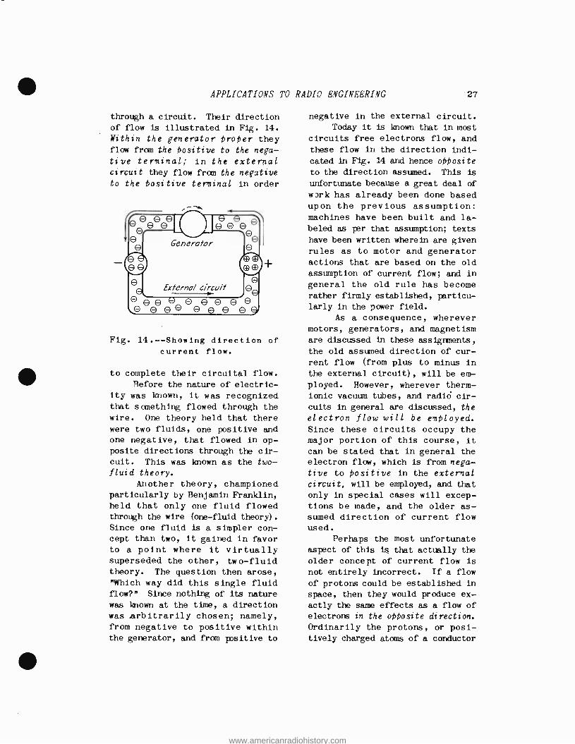
APPLICATIONS TO RADIO ENGINEERING 27
through a circuit. Their direction
of flow is illustrated in Fig. 14.
Within the generator Proper they flow from the Positive to the nega-
tive terminal; in the external circuit they flow from the negative
to the Positive terminal in order
OÓe e e
O Generator
O e External circuit 00
OOO o 0 O 0 OO ` O O 0 0 o e 0 O q
Fig. 14.-- Showing direction of
current flow.
to complete their circuital flow. Before the nature of electric-
ity was known, it was recognized that something flowed through the wire. One theory held that there
were two fluids, one positive and one negative, that flowed in op- posite directions through the cir- cuit. This was known as the two -
fluid theory.
Another theory, championed particularly by Benjamin Franklin, held that only one fluid flowed through the wire (one -fluid theory).
Since one fluid is a simpler con- cept than two, it gained in favor to a point where it virtually superseded the other, two -fluid theory. The question then arose,
"Which way did this single fluid flow ?" Since nothing of its nature
was known at the time, a direction was .arbitrarily chosen; namely, from negative to positive within the generator, and from positive to
negative in the external circuit. Today it is known that in most
circuits free electrons flow, and
these flow in the direction indi-
cated in Fig. 14 and hence opposite
to the direction assumed. This is
unfortunate because a great deal of
work has already been done based upon the previous assumption: machines have been built and la- beled as per that assumption; texts
have been written wherein are given rules as to motor and generator actions that are based on the old assumption of current flow; and in
general the old rule has become rather firmly established, particu-
larly in the power field.
As a consequence, wherever motors, generators, and magnetism
are discussed in these assignments,
the old assumed direction of cur- rent flow (from plus to minus in
the external circuit), will be em-
ployed. However, wherever therm -
ionic vacuum tubes, and radid cir-
cuits in general are discussed, the
electron flow will be employed. Since these circuits occupy the major portion of this course, it
can be stated that in general the
electron flow, which is from nega- tive to Positive in the external circuit, will be employed, and that
only in special cases will excep- tions be made, and the older as- sumed direction of current flow used.
Perhaps the most unfortunate aspect of this is that actually the
older concept of current flow is
not entirely incorrect. If a flow
of protons could be established in space, then they would produce ex-
actly the same effects as a flow of
electrons in the opposite direction.
Ordinarily the protons, or posi- tively charged atoms of a conductor
www.americanradiohistory.com

28 ELECTRON PHYSICS AND ELECTRON THEORY
(those that have lost electrons)
are too bulky to move, and are moreover held together by atomic forces or bonds which prevent their motion. Instead the lighter and hence more mobile free electrons move through the spaces within the conductor.
But in the cyclotron, .a device used in nuclear investigations, a
stream of Positive ions is whirled around in it in order to attain sufficient velocity to bombard the nuclei of targets placed in their
path. In this case the current flow
is actually that of positive char- ges, and they move from Plus to
minus.
In an electrolytic solution, such as salt water, when a poten- tial difference is established be- tween two electrodes immersed in
the brine, Positive sodium ions move from the Positive to the nega-
tive electrode, and an equal num-
ber of negative chlorine ions move
from the negative to the Positive
electrode. Thus half of the current flow is in the direction originally assumed, and half in the more modern electron direction; both directions are at least half right.
This is the way nature acts; there can be no quarreling with her edicts. Fortunately for the stu- dent, in most cases the modern electron flow is correct, and the older assumed direction of flow need be adopted in this course only in certain special cases. One must
have a flexible mind in sciençe; this question of current flow is a
simple example of such a requirement.
RESISTANCE. --It has been shown above that the free electrons in a
conductor are able to move through it, and in so doing produce an
electric current. The fundamental
reason for such freedom of motion is that matter is really more empty
space than substance, as was indi-
cated previously. However, the electrons are hampered to some ex-
tent by the atoms in the crystal- line arrangement (called a crystal
lattice structure). Presumably the electrons collide with the atoms, or at least are swerved by them if they come too close to the "sphere
of influence" of the atoms, where- upon their coordinated drift motion is converted, at least in part, in-
to haphazard thermal motion. Thus
the electrical energy is partially converted into heat, and forms the basis of action of the electric stove, electric furnace, and the incandescent lamp, as well.
The opposition to the drift motion of the electrons by the crystal lattice structure is called resistance. It is measured in a unit called the ohm, named in honor of George Simon Ohm, (1787 -1854) a
famous scientist who first correct-
ly gave the relationship between the current flow in amperes, the
electrical pressure in volts, and the resistance in ohms (Ohm's law).
This law will be given in a subse- quent technical assignment.
Factors Determining Resist- ance.- -The resistance of a con- ductor depends upon the following factors:
1. The material of which the
conductor is composed.
2. The cross -sectional area of the conductor.
3. The length of the conduc- tor.
4. The temperature of the con-
ductor.
The material determines the resistance in two ways: the number
www.americanradiohistory.com
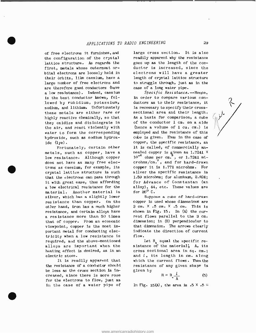
APPLICATIONS TO
of free electrons it firnishes,ard
the configuration of the crystal
lattice structure. As regards the
first, Metals whose outermost or-
bital electrons are loosely held in
their órbits, like caesium, have a
large number of free electrons and
are therefore good conductors (have
a low resistance). Indeed, caesium
is the best conductor known, fol-
lowed by rubidium, potassium,
sodium, and lithium. Unfortunately
these metals are either rare or
highly reactive chemically, so that
they oxidize and disintegrate in
the air, and react violently with
water to form the corresponding
hydroxide, such as sodium hydrox-
ide (lye) .
Fortunately, certain other
metals, such as copper, have a
low resistance. Although copper
does not have as many free elec-
trons as caesium, for example, its
crystal lattice structure is such
that the electrons can pass through
it with great ease, thus affording
a low electrical resistance for the
material. Another material is
silver, which has a slightly lower
resistance than copper. On the
other hand, iron has a much higher
resistance, and certain alloys have
a resistance more than 50 times
that of copper. From an economic
viewpoint, copper is the most im-
portant metal for conducting elec-
tricity when a low resistance is
required, and the above -mentioned
alloys are important when the
heating effect is desired, as in an
electric stove.
It is readily apparent that
the resistance of a conductor should
be less as the cross section is in-
creased, since there is more room
for the electrons to flow, just as
in the case of a water pipe of
RADIO ENGINEERING 29
large cross section. It is also readily apparent why the resistance
goes up as the length of the con- ductor is increased, since the
electrons will have a greater length of crystal lattice structure
to struggle through, just as in the
case of a long water pipe.
Specific Resistance. -- Hence, in order to compare various con- ductors as to their resistance, it
is necessary to specify their cross -
sectional area and their length.
As a basis for comparison, a cube
of the conductor 1 cm. on a side (hence a volume of 1 cu. cm.) is
employed and the resistance of this
cube is given. Thus in the case of
copper, the specific resistance, as
it is called, of commercially an- nealed copper is given as 1.7211 X
10-e ohms per cm. , or 1.7241 mi- crohms /cm.a, and for hard -drawn copper it is 1.771 microhms. For
silver the specific resistance is
1.59 microhms; for aluminum, 2.824;
for Advance of Constantan (an
alloy), 44, etc. These values are
for 20° C.
Suppose a cube of hard -drawn copper is used whose dimensions are
3 cm. X .5 cm. X .5 cm. This is
shown in Fig. 15. In (A) the cur- rent flows parallel to the 3 cm.
dimension; in (B) perpendicular to
that dimension. The arrows clearly
indicate the direction of current flow.
Let Rs equal the specific re-
sistance of the material, A, its
cross sectional area in sq. cm.;
and 1, its length in cm. along which the current flows. Then the
resistance of any given shape is
given by R= R
A (5)
In Fig. 15(A), the area is .5 X .5 =
www.americanradiohistory.com
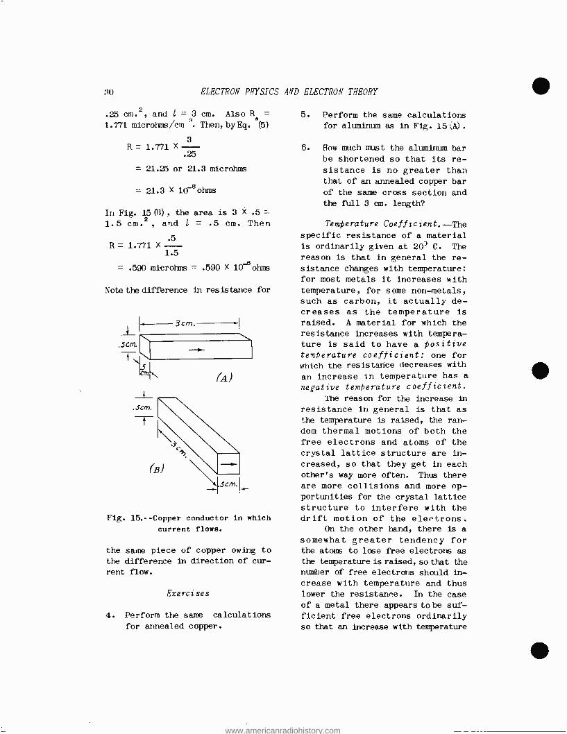
30 ELECTRON PHYSICS AND ELECTRON THEORY
.25 cm.2, and l = 3 cm. Also R =
1.771 microhms /cm `. Then, by Eq. (5)
3 R = 1.771 X
.25
= 21.25 or 21.3 microhms
= 21.3 X 10⁸ ohms
Ir, Fig. 15 (B) , the area is 3 X .5
1.5 cm.2, and l = .5 cm. Then
.5
1.5
= .590 microhms = .590 X learns
R=1.771X
Note the difference in resistance for
. 5 cm.
3cm.
(A)
Fig. 15. -- Copper conductor in which
current flows.
the same piece of copper owing to
the difference in direction of cur-
rent flow.
Exercises
4. Perform the same calculations
for annealed copper.
5. Perform the same calculations for aluminum as in Fig. 15 'A)
6. Row much must the aluminum bar
be shortened so that its re-
sistance is no greater than that of an annealed copper bar
of the same cross section and the full 3 cm. length?
Temperature Coefficient. -The specific resistance of a material is ordinarily given at 203 C. The
reason is that in general the re- sistance changes with temperature: for most metals it increases with
temperature, for some non -metals,
such as carbon, it actually de- creases as the temperature is
raised. A material for which the resistance increases with tempera- ture is said to have a positive temperature coefficient: one for which the resistance decreases with
an increase in temperature has a
negative temperature coefficient.
The reason for the increase in
resistance in general is that as
the temperature is raised, the ran- dom thermal motions of both the free electrons and atoms of the crystal lattice structure are in- creased, so that they get in each other's way more often. Thus there
are more collisions and more op- portunities for the crystal lattice
structure to interfere with the drift motion of the electrons.
On the other hand, there is a
somewhat greater tendency for the atoms to lose free electrons as
the temperature is raised, so that the number of free electrons should in- crease with temperature and thus lower the resistance. In the case
of a metal there appears to be suf- ficient free electrons ordinarily
so that an increase with temperature
www.americanradiohistory.com

APPLICATIONS TO RADIO ENGINEERING 31
does not materially lower the
resistance in this respect, but
the greater number of collisions,
on the other hand, tends to raise
the resistance. In the case of relatively poor conductors, such
as carbon, increase in temperature
either increases the number of free
electrons, or else modifies the
crystal structure in a favorable
direction, or both, so that the
resistance decreases. In the case
of resistance standards, such as
are used in measurements, it is
highly desirable that their re-
sistance does not vary with tem- perature; i.e., a zero temperature
coefficient is desired. Many alloys have been developed for this purpose, particularly manganin,
an alloy of copper, manganese, nickel and some iron, which has
a practically zero temperature coefficient, and is also particu-
larly stable in resistance with
time.
If the temperature coefficient
of a metal is known, the actual
resistance of a conductor of that
metal at a given temperature may he easily calculated. The temper-
ature coefficient is expressed in
terms of the decimal variation in
resistance per degree C. The formula for computing the multi-
plying factor is
F= 1+off (6)
where F is the factor by which the
resistance is to be multiplied, T
is the temperature change from 20°
C, and a is the temperature co-
efficient. A simple problem will
make the use of this formula clear:
A coil is wound with 450 feet of No. 30 copper wire, the resist-
ance of which at 20° C is 103.2
ohms per thousand feet. What is
the resistance of the coil at 50° C?
At 20° C, the resistance is
R= 103.2 X 450/1,000
= 46.44 ohms
From tables the temperature
coefficient a of commercial annealed
copper is found to be .00393. (The
temperature coefficient of most
pure metals in the range of ordinary
temperatures is between .003 and
.005 so that an approximation of
.001 will allow a workable calcu-
lation if tables are not available.
This does not apply to alloys.) The temperature T is to be in-
creased from 20° to 50 °, a change
of 50 - 20 = 30° C. Then, from
Eq. (6)
F = i + (.00393 X 30) = 1.118
so that
h = 46.44 X 1.118 = 51.92 ohms
This is a variation of (51.92 - 46.44)/48.44 = 11.8 per cent for a 30° C rise in temperature. Such a
change can be of marked importance
in many types of radio equipment. While the value of x is strictly speaking correct only at 20° C, it
may be used over other temperature
ranges with no appreciable error;
i.e., the same coefficient may be
used from below 20° C to as high
as 1000° C.
At very low temperatures some
metals, notably tin, mercury, and
lead show extremely low resistance;
indeed, practically none at all. This condition is known as "super -
conductivity ", and can be explained
only by very advanced theories and methods known as "quantum mechanics ",
www.americanradiohistory.com
32. ELECTRON PHYSICS AND ELECTRON THEORY
which are beyond the scope of this
course. The resistance decreases
with temperature in the form of a
curve until a certain critical temperature is reached (close to
absolute zero, which is 0° K or
-273° C), at which point the re-
sistance apparently drops to zero.
For tin the critical temperature
is 3.74° K; for mercury, 4.19° K;
and for lead, 7.20° K. Liquid helium is used for such cooling purposes.
Below the critical temperature,
if a ring of the metal is employed,
and a permanent magnet suddenly thrust in it, the cutting of the
closed conductor by the magnetic
lines of force will induce a mo-
mentary voltage, which in turn
will cause a current to flow for
days. This is an interesting phenomenon, even though there does
not appear to be any practical use
for it at present.
Exercises
7. Calculate the resistance of a length of copper wire at 60° C when its resistance at 20° C
is 140 ohms.
8. A radio coil of 0.1 ohm re- sistance at 20° C is employed in an airplane receiving set. During flight a temperature of
-50° C is encountered. What is the resistance of the coil at the latter temperature.
9. On the ground the temperature in the plane may reach 80 °C. What is the resistance of the coil under these conditions?
INSULATORS. --Many materials do not conduct electricity; they are
known as insulators; and are just
as important as conductors. The reason is that by surrounding conductors with insulating covers,
the electric current flow can be confined to the desired conducting
paths. Thus insulators act as the
walls of a water pipe; the con- ductor, as the hole in the pipe.
The lack of conductivity ex-
hibited by insulators is owing to
a lack of free electrons in the
material. Most electro- negative
atoms, such as sulphur, make ex-
cellent insulators, because it will
be recalled that these atoms tend
to capture electrons rather than
to yield them up as free electrons.
However, most compounds containing
metals are good insulators. For
example, while sodium is one of the
best conductors known (as explained
previously), sodium chloride is a
good insulator in the crystalline
form. This is because the normally
free electron of the sodium atom is
held tightly by the chlorine atom in sodium chloride, and hence is
no longer free to provide con- ductivity.
In spite of the fact that in-
sulators have no free electrons (or very, very few) to provide con-
ductivity, nevertheless momentary
currents, known as charging cur- rents, can flow in them. The reason is best explained by means of Fig. 16. Asource of potential G i;; applied to two conducting plates Pi and P2. For the polarity
shown for the generator, P1 has an
excess of electrons and is nega-
tive; P2 has a deficit of electrons and hence a relative excess of protons, and is therefore positive.
Between the two plates is an in-
sulating material, I. The atoms in this material have no free elec-
www.americanradiohistory.com

APPLICATIONS TO RADIO ENGINEERING 33
trons, but the orbital electrons
are acted upon by the Coulomb forces owing to the charges in
the two plates.
As a result the orbits are
distorted as shown. The electrons
Fig. 16. -- Distortion of orbits of
electrons in atoms of an insulator.
are on the average closer to the
positive plate P2 than they are to
the negative plate P1. When the
switch S was first closed, elec-
trons were forced into Pi; elec-
trons were drawn out of P2, and the
electrons in I changed from ap- proximately circular orbits around
the nuclei into the distorted forms
shown.
The momentary flow of electrons
into P1 and out of P2 represented a
momentary current flow; correspond-
ing to this there was a momentary
charging current flow in I. This
came about as follows: When the electrons were revolving. in ap-
proximately circular orbits about
their nuclei, they were as much to
one side of the nuclei as to the
other side; their average positions
were about the same as those of the
nuclei. But when the orbits are
distorted, their average bositions are slightly to the right of the
nuclei. This average displacement
can justifiably be regarded as a
momentary electron flow to the
right, and thus there occurs in the
insulator I a momentary current
flow, known as a charging current,
equal and corresponding to the electron flow in the metallic parts
of the circuit.
After the momentary flow ceases, the plates are charged as
shown, and represent a condenser
that has been charged to the po-
tential of G. If the potential of
G were to be reversed, an opposite
distortion in the orbital paths of
the electrons of I would occur, and
a momentary opbosite flow of cur-
rent in the system would occur. Thus, if G is an alternating -in-
stead of a direct- current generator,
a steady alternating current can
flow in the circuit, even though I
is an insulator. This will be
discussed in greater detail in later assignments.
Even in the best of insulators
there are some free electrons, pro-
duced by various causes, so that
some conductivity occurs. The
amount is so small, however, that
for most practical purposes it can
be taken as zero, and many in- sulators can be regarded as well -
nigh perfect. However, if the
potential applied to the insulator
is made sufficiently high, the
electron structure can be dis- rupted, and free electrons pro- duced, whereupon the insulator suddenly becomes a conductor. The
attendant arc or spark through the
material in general disintegrates
it, so that it no longer functions
as an insulator when the voltage is
reduced. Some materials exhibit
partial conductivity and are known
as partial conductors. An example
www.americanradiohistory.com
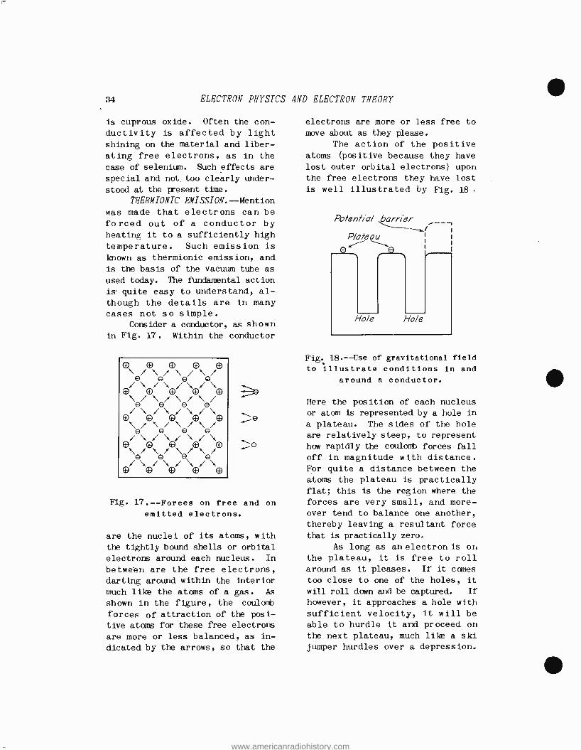
34 ELECTRON PHYSICS
is cuprous oxide. Often the con-
ductivity is affected by light shining on the material and liber-
ating free electrons, as in the
case of selenium. Such effects are
special and not. too clearly under-
stood at the present time.
TKERMIONIC EMISSION. -Mention was made that electrons can be forced out of a conductor by heating it to a sufficiently high
temperature. Such emission is known as thermionic emission, and is the basis of the vacuum tube as
used today. The fundamental action
is quite easy to understand, al-
though the details are in many cases not so simple.
Consider a conductor, as shown in Fig. 17. Within the conductor
Fig. 17. -- Forces on free and on
emitted electrons.
are the nuclei of its atoms, with
the tightly bound shells or orbital
electrons around each nucleus. In
between are the free electrons, darting around within the interior
much like the atoms of a gas. As
shown in the figure, the coulomb
forces of attraction of the posi- tive atoms for these free electrons
are more or less balanced, as in-
dicated by the arrows, so that the
AND ELECTRON THEORY
electrons are more or less free to
move about as they please.
The action of the positive atoms (positive because they have lost outer orbital electrons) upon the free electrons they have lost
is well illustrated by Fig. 18 .
Potential barrier
Plateau
Fig. 18. --Use of gravitational field
to illustrate conditions in and
around a conductor.
Here the position of each nucleus or atom is represented by a hole in
a plateau. The sides of the hole
are relatively steep, to represent
how rapidly the coulomb forces fall
off in magnitude with distance. For quite a distance between the atoms the plateau is practically flat; this is the region where the forces are very small, and more- over tend to balance one another, thereby leaving a resultant force
that is practically zero.
As long as an electron is on the plateau, it is free to roll
around as it pleases. If it cames
too close to one of the holes, it
will roll down and be captured. If
however, it approaches a hole with
sufficient velocity, it will be able to hurdle it and proceed on the next plateau, much like a ski jumper hurdles over a depression.
www.americanradiohistory.com
APPLICATIONS TO RADIO ENGINEERING 35
The gravitational model presented can also illustrate the action of heat: suppose the model is shaken
vigorously; it is clear that elec-
trons will be jiggled out of the
holes onto the plateaus in a manner
similar to that by which the outer electrons of the atoms are knocked
out of their orbits by heat energy. So far all that has been de-
scribed is the production of free electrons. Returning to Fig. 17
consider an electron that tries to
pass through the boundary surface of the conductor. The moment this
occurs, all the positive atoms left
behind now unite in trying to pull
the electron back. This is illus-
trated by the three electrons shown
to the right of the conductor in
Fig. 17; the arrows show that the
forces are to the left and hence of
attraction, tending to pull the
electron back into the conductor. Compare these with the forces
on an electron inside of the con-
ductor and it will be clear that an
electron must have a far greater velocity to escape from the con- ductor than to wander around in it.
The same effect is illustrated in
Fig. 18 by the dotted line hill labelled "Potential Barrier ". An
electron requires excess velocity and hence kinetic energy to sur- mount this potential barrier and escape from the conductor.
Once the electron escapes and moves to a sufficient distance from
the surface, the coulomb forpes of
attraction pictured in Fig. 17-be-
come so weak that it is free to
wander about in free space. Thus,
in a vacuum tube, electrons emitted
from an electrode called a cathode, into the vacuum within the glass envelope, can now be attracted to any other positive electrode in the
enclosure, such as a plate, and give rise to the plate current flow in the tube.
It is clear that a much great -
er amount of energy must be im-
parted to a conductor to cause electron emission from its surface
than is required merely to free or-
bital electrons so that they can
wander freely within the material.
The required energy can be imparted
to the electron in several ways.
One important way is to radiate the
surface with light energy of the
proper wavelength; such emission is
known as photoelectric emission,
and will be discussed farther on.
Another method is to heat the
conductor, thus agitating the atoms
and free electrons to such an ex-
tent that the latter are forced out
of the surface. This is known as
thernionic emission. The amount of
energy required to cause an electron
to hurdle the potential barrier is
known as the work function, and depends upon the material used and
the nature of its surface. The work function is measured in volts,
because volts times charge equals energy, just as volts times current
equals rate of energy dissipation or power.
This will be made clearer by reference to Fig. 19. Again two plates or electrodes are shown, with a vacuum in between. (It is
desirable in general that there be
no obstructions, such as oxygen or nitrogen atoms from the air, to
prevent the free motion of the electrons.) Suppose the plates are
given the charges shown by means of a generator or battery so that
a difference of potential. V exists
between the plates.
An electron placed as shown,
and having a charge e, will be
www.americanradiohistory.com

36 ELECTRON PHYSICS AND ELECTRON THEORY
acted upon by a force of repulsion by the left -hand plate, and a force of attraction by the right -hand plate, so that there is a total force accelerating it to the right.
The electron gains in velocity and
V
+ +
+ +
111111111111111111
Fig. 19.-- Conversion of potential energy into kinetic energy; elec-
tron falling through a difference
in potential.
hence kinetic energy at the expense
of potential energy of position. Thus, when it is next to the left -
hand plate it has a maximum amount
of potential energy, equal to Ve,
but no kinetic energy, since it is
assumed at rest there. When it
reaches the right -hand plate, it has
a maximum amount of velocity and hence kinetic energy, but it has no
potential energy. All the potential
energy has been converted into kinetic energy. The latter is
given by Eq. (3), so
of
at
Ve = (1/2) mv2 (7)
The action is similar to that
a ball falling from a height: the height the ball has poten-
tial energy of position but no kinetic energy; at the ground it
has a high velocity and hence
kinetic energy, but no more poten- tial energy. In the same way, an electron (or other charged body) is
said to fall through a difference in potential, and often its veloci- ty is expressed in electron volts; i.e., in terms of the difference in potential through which it would have to fall to acquire the given velocity.
Even if the electron acquires its velocity through thermal agi- tation, its velocity can neverthe-
less be expressed in terms of so many electron volts. Consider now
the critical velocity that will carry an electron past the surface potential barrier. This can be expressed in terms of so many volts, and the required work func- tion is therefore measured in
volts. For example, the work func- tion for tungsten is 4.54 volts.
This is a very high value, and requires that the tungsten cathode be heated to about 2400° K. before appreciable thermionic emission occurs. Fortunately, this high temperature is safe because the melting point of tungsten is 3655° K. This brings out an important characteristic of a thermionic emitter: it must have as high a
melting Point together with as low a work function as possible in
order to be a practical emitter. The significance of this is that
the bonds or forces holding the crystal lattice structure together
must be as great as possible, and the potential barrier for the elec-
trons must be as low as possible,
in order that heating the material
will produce copious emission at a temperature insufficient to melt
or vaporize the material.
For this reason caesium, which has a work function of but
www.americanradiohistory.com
APPLICATIONS
1.81 volts, is not suited for thermionic emission because it
vaporizes so easily; it would tend unduly to evaporate even at the low temperature required for satisfactory emission. On the other hand, it is exceedingly well
adapted for photoelectric emission,
In which case it is operated at practically room temperature. More
will be said about this later. It is found that for medium -
voltage tubes an emitter consisting
of thorium and tungsten is pre- ferable to pure tungsten. The reason is that the work function is only 2.63 volts, so that at a safe operating temperature of 1800 to 2000° K. the emission is many times
that from tungsten. At the same time it must not be overlooked that
the lower operating temperature of
the thoriated- tungsten cathode means that much less electrical heating power is required, so that
the vacuum tube operates at a
higher overall efficiency as a re-
sult.
An even more efficient emitter
is a mixture of barium and strontium oxides on a special base metal such
as Konel metal. This composite cathode at 1000° K. emits as many electrons as a tungsten filament at
2300° K. Unfortunately this type of emitter is sensitive to positive
ion bombardment and cannot be heatea to as high a temperature as tungsten for the purpose of out -
gassing the tube, so that it is
limited to the lower - voltage tubes,
such as small transmitting tubes and the ordinary receiver tubes. However, such large quantities of
the latter are employed that the
oxide -coated cathode is neverthe- less the most -used type of therm - ionic emitter.
TO RADIO ENGINEERING 37
PHOTOELECTRIC EMISSION.- -Ordi- narily light, heat, and radio energy are regarded as being elec- tromagnetic waves in space or radiant energy. A wave motion in a medium is characterized by its filling or pervading the medium uni,for'zly. Thus every point in a
medium through which radiant energy is passing is regarded as partaking
in the wave motion.
In spite of this, there is
evidence to show that the above electromagnetic energy does not spread uniformly through space, but is confined to little pellets or
bundles of energy called photons. The picture concerning this is not clear, as was indicated in the quotation from G. E. M. Jaunrey's book at the beginning of this technical assignment. Certain properties of light, such as dif- fraction and interference effects in general, are explained in terms of wave motion only, whereas such effects as photoemission, for ex- ample, are explained in terms of photons of light.
Probably both wave motion and particle properties are associated with the phenomenon known as radi- ant energy; each property is used where it explains best the results rooted. For example, when weak blue light falls on a suitable surface, a few electrons are emitted from it with certain rather high velocities. A strong blue light causes more electrons to be emitted, but each has the same velocity as the few emitted by the weak blue light.
On the other hand, a strong red light will emit as many elec- trons from the surface as the strong blue light, but each elec- tron will came out with a much lower
www.americanradiohistory.com

3R ELECTRON PHYSICS AND ELECTRON THEORY
velocity. A weak red light will produce the same velocity of emis-
sion; fewer electrons will be emi tted.
From the viewpoint of wave motion this is a very puzzling phenomenon. A strong red light on
say, a square foot of the surface
should represent a higher but uniform energy density on the sur-
face than a weak blue light. Thus
each free electron of the surface
should receive more energy from the strong red light than from the
weak blue light. The received energy is partly
used up to overcome the work function of the material, and the
rest appears in the form of kinetic
energy of the emitted electron; i.e., the electron issues from the
surface with a certain amount of
velocity of emission. According to the theory of wave motion, the
velocity of emission of the elec-
tron should be greater for a strong
red light than for a weak blue light.
Since the opposite is found to
be the case, the only explanation
is that energy is confined to small
pellets or quanta of energy. These
quanta are given the special name
of Photons in the case of radiant
energy. Apparently there is more
energy in a photon of blue light
than in a photon of red light, and
a weak light consists of few
photons whereas a strong light con-
sists of many photons. If a photon
impinges upon an electron, the
latter absorbs it in its entirety
if the energy content is above a
certain minimum amount, and there-
upon emerges with a corresponding
velocity of emission.
The energy content W of a
photon is given by a very simple
formula: W = hf (R)
Where h is a constant of nature equal to 6.55 X 10 -27 erg sec. and
is named after Max Planck, a famous
German physicist, and f is the
frequency of the wave motion. For
example, the frequency of a certain
hue of blue light is 0.7X 10¹⁵c.p.s., (cycles per second) hence the energy in one photon of blue light is
WD = 6.55 X 10-27 X 0.7 X 1016
= 4.59 X 10 -12 erg
The frequency of a certain shade of red light is 0.45 X 10¹⁵ c.p.s.,
hence the energy in one photon is
Wr = 6.55 X 10-27 X 0.45 X 1016
= 2.95 X 10 -12
or considerably less than that in
blue light. The kinetic energy owing to the
velocity of emission was first given by Einstein in the form of a very simple law:
K.E. = hf - :e x 107 (9)
Here K.E. is the kinetic energy of the electron and, by Eq. (3), is equal
to 1/2 mv2, where m is the mass of
the electron and v is its velocity
(of emission). The quantity hf is
the energy in ergs if the photon impinging on the surface is given
by Eq. (S); gi is the work function
of the surface in volts; and e is
the charge on the electron in coulombs, namely, 1.59 x 10'19 coulombs.
As an example, suppose blue
light evaluated above impinges upon
www.americanradiohistory.com

APPLICATIONS TO RADIO ENGINEERING 39
a caesium surface, whose work function is 1.81 volts. The energy
in one photon of the above light was calculated to be 4.59 X 1.0-12 erg. The kinetic energy of emission,
by Eq. (9), is
K.E. = 4.59 X 10⁻¹² - 1.81 X 1.59
X 10-19 X 107
= 4.59 X 10`12 -2.88X 10-12
= 1.71 X 10⁻¹²
This is the kinetic energy per elec-
tron emitted, and is equal to (1/2) /mv2, where m = 8.99 X 10 -28 gram. Thus
K.E. = (1/2) mv2
If both sides of the equation be multiplied by 2, and then divided by m, there is obtained
2 K.E. 2 - V m
Now take the square root of both
sides, and obtain
V = m
- cm./sec. (10)
For the values given above, namely,
R.E. = 1.71 X 10 -12 erg, and m = 8.99 X 10⁻²⁸ gram, the velocity is
found to be, by substitution in Eq. (10) :
X 1.71 X 10 -12 = /38.1X1014
8.99 X 10-28
= 6.18 X 107 cm./sec.
This represents the maximum velocity
with which an electron is emitted.
Most of' the electrons encounter atoms on the surface which extract
some energy from them, so that they emerge with lower velocities.
Exercises
10. Calculate the maximum velocity
of emission for the red light described above.
Eq., (9) brings out another very important point besides that of velocity of emission. Suppose the
frequency of the radiation is very low. The energy content in its
photons will be also low. Suppose
the work function of the material is high. In that case Oe X 107 may exceed the photon energy con- tent hf, so that the kinetic energy
K.E. comes out negative, and the corresponding velocity will be imaginary. This simply means that
actually the electrons will not be emitted.
Indeed, for some particular frequency of the radiation hf will just equal 0e X 107 and K.E. will
then be zero. This means that at
this frequency the electrons are just emitted with no left -over velocity. The frequency at which this occurs is known as the thresh - hold frequency. It is found very simply from Eq. (9) by setting K.E. equal to zero and solving for f.
Thus
0= hf - Oe X 107
Transposing,
hf = Oe X 107
or
f=Oe X 107
h al)
An important point to note here is that the higher the work function of the material, the higher is the threshhold frequency
at which photoemission begins. Thus for tungsten, with a work function of 4.54 volts, photo-
www.americanradiohistory.com
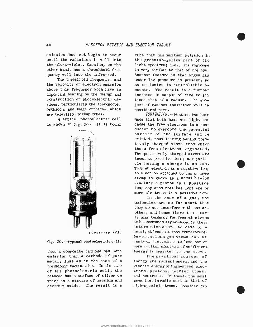
40 ELECTRON PHYSICS AND ELECTRON THEORY
emission does not begin to occur until the radiation is well into
the ultra -violet. Caesium, on the
other hand, has a threshhold fre-
quency well into the infra -red.
The threshhold frequency, and
the velocity of electron emission
above this frequency both have an
important bearing on the design and
construction of photoelectric de-
vices, particularly the iconoscope,
orthicon, and image orthicon, which
are television pickup tubes.
A typical photoelectric cell
is shown in Fig. 20 It is found
(Courtrsy RCA)
20.-- Typical photoelectric cell.
that a composite cathode has more
emission than a cathode of pure
metal, just as in the case of a
thermionic vacuum tube. In the ca..e
of the photoelectric cell, the
cathode has a surface of silver on
which is a mixture of caesium and
caesium oxide. The result is a
tube that has maximum emission in the greenish -yellow part of the light spect -mm; i.e., its response is very similar to that of the eye. Another feature is that argon gas under for pressure is present, so as to ionize in controllable a- mounts. The result is a further increase in output of five to six times that of a vacuum. The sub- ject of gaseous ionization will be considered next.
IONIZATION. --Mention has been made that both heat and light can cause the free electrons in a con- ductor to overcome the potential barrier of the surface and be emitted, thus leaving behind posi- tively charged atoms from which these free electrons orginated, The positively charged atoms are known as positive ions; any parti- cle having a charge is an ion. Thus an electron is a negative ion;
an electron attached to one or mrre atoms is known as a negative -ion cluster; a proton is a positive ion; any atom that has loot one or more electrons is a positive ion.
In the case of a gas, the molecules are so far apart that they do not interfere with one ar- other, and hence there is no par- ticular tendency for free electrons to be spontaneously produced by their interaction as in the case of a metal, at least at room temperature. Nevertheless gas atoms can be ionized; i.e., caused to lose one or more orbital electrons if sufficient energy is imparted to the atoms.
The practical sources of energy are radiant energy and the kinetic energy of high -speed elec- trons, protons, heavier atorr.s, and neutrons. Of these, the most important in radio work is that of
high- speed electrons. Consider two
www.americanradiohistory.com

APPLICATIONS TO RADIO ENGINEERING 41
electrodes between which is placed
some gas that it is desired to ion-
ize, see Fig. 21. A source of potential V is applied to the plates.
glassy¡ envelope
V
Fig. 21 . --Gas to be ionized by electron bombardment.
Owing to cosmic rays and minute a- mounts of radioactive material in
the glass walls, a few gas atoms
are split apart by these agencies into electrons and positive ions.
Under the action of the applied
potential, the electrons move to the positive plate, and the positive
ion' to the negative plate. The electrons, having little mass, move
rapidly; the ions, being relatively
heavy, move much more leisurely. However, the electrons can-
not proceed without interruption to the positive plate because of the presence of the neutral (un-
ionized) gas atoms. Thus the electrons accelerate in a free space up to a certain velocity, strike a gas atom, from which they may rebound in an entirely dif- ferent direction, but the impressed
electric field continues to urge them toward the anode (positive electrode) so that they start out again, are accelerated to a certain velocity when they strike another atom, and so on.
The net velocity gained in a forward direction between col- lisions clearly depends upon the mean (average) spacing between atoms. This is known as the mean free bath. If the number of gas atoms in the enclosure is decreased
(pressure is reduced), then the mean free path is increased, and the electrons can acquire a higher velocity and hence greater kinetic energy between collisions. Or, if the pressure is not reduced, but the potential V is increased, a
higher kinetic energy will be ob- tained in the original mean free path.
If the kinetic energy attained is sufficient, the bombarding elec- tron may be able to knock out one
or more electrons from an atom of the gas, thus producing more free electrons as well as a positive ion. This process is known as ionization by collision, and by its means a large number of free elec- trons and positive ions are pro- duced in the enclosure.
It is immediately evident that the gas now resembles the interior of a metal, in that free electrons and positive ions are present, (except that the ions and atoms of the gas do not exhibit the uniform pattern of the crystal lattice structure of a metal) . The gas therefore becomes a conductor, but there is one important difference: in a metal the voltage drop is
directly proportional to the length and inversely proportional to the cross - sectional area of the metal, whereas in a gas the voltage drop is more or less fixed and rather independent of these factors. The voltage drop is known as the ion- izing botential, and its value de- pends upon the structure of the
www.americanradiohistory.com
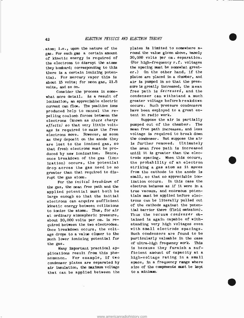
42 ELECTRON PHYSICS AND ELECTRON THEORY
atom; i.e., upon the nature of the
gas. For each gas a certain amount
of kinetic energy is required of
the electrons to disrupt the atoms
they bombard; corresponding to this
there is a certain ionizing poten-
tial. For mercury vapor this is
about 15 volts; for neon gas, 21.5
volts, and so on.
Consider the process in some-
what more detail. As a result of
ionization, an appreciable electric
current can flow. The positive ions
produced help to cancel the re-
pelling coulomb forces between the
electrons (known as space charge
effects) so that very little volt-
age is required to make the free
electrons move. However, as soon
as they deposit on the anode they
are lost to the ionized gas, so
that fresh electrons must be pro-
duced by new ionization. Hence,
once breakdown of the gas (ion-
ization) occurs, the potential
drop across the gas need be no
greater than that required to dis-
rupt the gas atoms.
For the initial breakdown of
the gas, the mean free path and the
applied potential must both be
large enough so that the initial
electrons can acquire sufficient
kinetic energy between collisions
to ionize the atoms. Thus, for air
at ordinary atmospheric pressure,
about 30,000 volts per cm. is re-
quired between the two electrodes.
Once breakdown occurs, the volt-
age drops to a value closer to the
much lower ionizing potential for
the gas.
Many important practical ap-
plications result from this phe-
nomenon. For example, if two
condenser plates are separated by
air insulation, the maximum voltage
that can be applied between the
plates is limited to somewhere a- round the value given above, namely
30,000 volts per cm. separation.
(For high -frequency r.f. voltages
the spacing must be somewhat great-
er.) On the other hand, if the
plates are placed in a chamber, and
air is pumped in so that the pres-
sure is greatly increased, the mean free path is decreased, and the condenser can withstand a much greater voltage beforebreakdown occurs. Such pressure condensers
have been employed to a great ex- tent in radio work.
Suppose the air is partially pumped out of the chamber. The mean free path increases, and less
voltage is required to break down the condenser. But suppose the air
is further removed. Ultimately the mean free path is increased until it is greater than the elec-
trode spacing. When this occurs,
the probability of an electron striking a gas atom as it moves
from the cathode to the anode is
small, so that no appreciable ion-
ization occurs. In this case the
electron behaves as if it were in a
true vacuum, and enormous poten- tials must be applied before elec-
trons can be literally pulled out
of the cathode against the poten-
tial barrier there (field emission).
Thus the vacuum condenser ob-
tained is again capable of with-
standing very high voltages even
with small electrode spacings. Such condensers are found to be
particularly valuable in the case
of ultra -high frequency work. This
is because they furnish a suf- ficient amount of capacity at a high -voltage rating in a small space, in a frequency range where
size of the components must be kept
to a minimum,
www.americanradiohistory.com
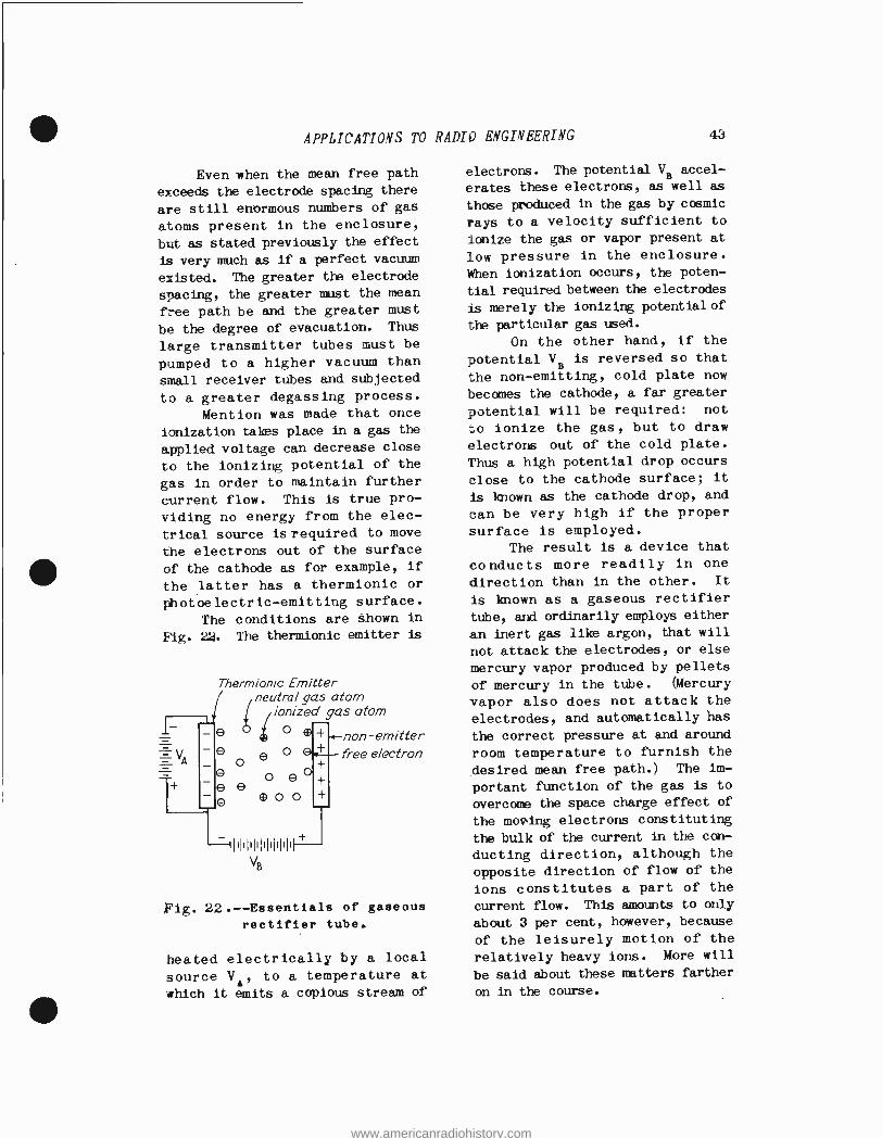
APPLICATIONS TO RADIO ENGINEERING 43
Even when the mean free path
exceeds the electrode spacing there
are still enormous numbers of gas
atoms present in the enclosure,
but as stated previously the effect
is very much as if a perfect vacuum
existed. The greater the electrode
spacing, the greater must the mean
free path be and the greater must
be the degree of evacuation. Thus
large transmitter tubes must be
pumped to a higher vacuum than
small receiver tubes and subjected
to a greater degassing process.
Mention was made that once
ionization takes place in a gas the
applied voltage can decrease close
to the ionizing potential of the
gas in order to maintain further
current flow. This is true pro-
viding no energy from the elec-
trical source is required to move
the electrons out of the surface
of the cathode as for example, if
the latter has a thermionic or
Photoelectric-emitting surface.
The conditions are shown in
Fig. 22. The thermionic emitter is
Thermionic Emitter neutral gas atom
ionized gas atom
o
o
e ° e o e e e
® O O
non - emitter free electron
Fig. 22. -- Essentials of gaseous
rectifier tube.
heated electrically by a local
source VA, to a temperature at
which it emits a copious stream of
electrons. The potential VB accel-
erates these electrons, as well as
those produced in the gas by cosmic
rays to a velocity sufficient to
ionize the gas or vapor present at
low pressure in the enclosure.
When ionization occurs, the poten-
tial required between the electrodes
is merely the ionizing potential of
the particular gas used.
On the other hand, if the
potential VB is reversed so that
the non -emitting, cold plate now
becomes the cathode, a far greater
potential will be required: not
to ionize the gas, but to draw
electrons out of the cold plate.
Thus a high potential drop occurs
close to the cathode surface; it
is known as the cathode drop, and
can be very high if the proper
surface is employed. The result is a device that
conducts more readily in one
direction than in the other. It
is known as a gaseous rectifier
tube, and ordinarily employs either
an inert gas like argon, that will
not attack the electrodes, or else
mercury vapor produced by pellets
of mercury in the tube. (Mercury
vapor also does not attack the
electrodes, and automatically has
the correct pressure at and around
room temperature to furnish the
desired mean free path.) The im-
portant function of the gas is to
overcome the space charge effect of
the moving electrons constituting
the bulk of the current in the con-
ducting direction, although the
opposite direction of flow of the
ions constitutes a part of the
current flow. This amounts to only
about 3 per cent, however, because
of the leisurely motion of the
relatively heavy ions. More will
be said about these matters farther
on in the course.
www.americanradiohistory.com

44 ELECTRON PHYSICS AND ELECTRON THEORY
ELECTRIC FIELDS. -- Throughout this assignment one thing has been apparent, and that is that the coulomb forces between the electri- cally- charged particles have a
major role in explaining chemical action, ionization, conductivity in a metal, and the like. It will
be found farther on in the course that radiation from antennas, wave motion in transmission lines, wave guides, and cavity resonators, etc.,
all depend upon the properties of the electric field. Hence an ele- mentary description of the elec- tric field and its characteristics
is in order here.
Single Charge. --In Fig. 23 is
shown a negatively charged body, such as an electron. As stated
\ O
Fig. 23.- -Force on a unit positive
test charge in an electron field.
previously, it exerts a force of
attraction on a posiive charge anywhere in space. The force varies
inversely as the square of the dis-
tance, as given by Coulomb's law, Eq. (1), so that the force of at-
traction becomes exceedingly small
at any great distance from the electron. Nevertheless, theoreti- cally, the force exists even at an infinite distance, and is
directed radially inward toward the electron.
To represent this force effect of the electron (or any other charged particle), Michael Faraday, an eminent English scientist, as- sumed that there were tubes or Lines of force existing in the space around the electron. In the
case of a single charge isolated in space, these lines were direc- ted radially from or to the charge. By convention (just as in the case of current flow), these lines of force were considered converging on a negative charge, such as the
electron, and diverging from a
positive charge, such as the pro- ton. In short, the direction of the line of force is that in which a positive charge would move when exposed to the action of the given charge.
The magnitude of the force depends upon the magnitude of the given charge, and the distance from the charge of the point in space at which the force is measured. The fact that the force decreases as the square of the distance indi- cates that if a series of radial lines be drawn about the charge, the way in which they spread out through space will follow exactly this inverse square law. Hence the number of lines, passing through any region; i.e., their density, should indicate the magnitude of the force in that region.
This will be more evident from Fig. 24. Here a positive charge is assumed isolated in space. From it emanate a series of electric field lines in all directions to infinity, so that the charge looks like a gigantic pin cushion.
At a certain distance from the charge imagine a spherical
www.americanradiohistory.com
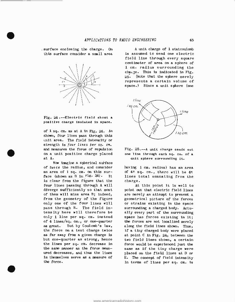
APPLICATIONS TO
.surface enclosing the charge. On
this surface consider a small area
Fig. 24. -- Electric field about a
positive charge isolated in space.
of 1 sq. cm. as at A in Fig. 24. As
shown, four lines pass through this
unit area. The field intensity or
strength is four lines Per sq. cart.
and measures the force of repulsion
en a unit positive charge placed
at A.
Now imagine a spherical surface
of twice the radius, and consider
an area of 1 sq. cm. on this sur- face (shown as B in Nig l). It
is clear from the figure that the
four lines passing through A will diverge sufficiently so that most of them will miss area B; indeed,
from the geometry of the figure only one of the four lines will
pass through B. The field in- tensity here will therefore be only 1 line per sq. cm. instead of 4 lines /sq. cm., or one -quarter
as great. But by Coulomb's law,
the force on a test charge twice as far away from a given charge is
but one -quarter as strong, hence
the lines per sq. cm. decrease in
the sane manner as the force meas-
ured decreases, and thus the lines
in thenselves serve as a measure of
the force.
RADIO ENGINEERING 45
A unit charge of 1 statcoulomb
is assumed to send one electric field line through every square centimeter of area on a sphere of
1 cm. radius surrounding the chal;e. This is indicated in Fig.
25. (Note that the sphere merely represents a certain volume of space.) Since a unit sphere (one
Fig. 25. --A unit charge sends out
one line through each sq. cm. of a
unit sphere surrounding it.
having i cm. radius) has an area of 4n: sq. cm., there will be 4n lines total emanating from the charge.
At this point it is well to
point out that electric field lines
are merely an attempt to present a geometrical picture of the forces or strains existing in the space surrounding a charged body. Actu- ally every part of the surrounding
space has forces existing in it;
the forces are not localized merely
along the field lines shown. Thus,
if a tiny charged body were placed
at point C in Fig. 24, between the two field lines shown, a certain force would be experienced just the
same as if the tiny charge were placed on the field lines at D or
E. The concept of field intensity
in terms of lines per sq. cm. is
www.americanradiohistory.com

46 ELECTRON PHYSICS AND ELECTRON THEORY
merely a convenient method of
portraying or visualizing the field
of force around one or more charged
bodies.
Two or More Charges. -Now con- sider two oppositely charged bodies
separated by a certain distance, as
indicated in Fig. 26 What are the
magnitude and direction of the
Fig. 26 .-- Resultant field for two
charged bodies.
forces on a third, test charge, in
the surrounding space? To answer
this question, consider each charge
by itself. As explained above, radial lines of force issue from it
or converge to it (depending upon
its polarity) in the manner illus-
trated in Figs. 24 and 25. For the
left -hand positive charge Q1 a
series of lines of density depending
upon the strength of the charge emanate from it like a pincushion.
For the right -hand negative charge
Q2 a similar series of lines of
density depending upon the strength
of the charge converge on it in a
similar manner. Each set is called
an elementary field.
Each set of lines can be as-
sumed to exist in siiace independ-
ently of the other set; the lines of
one set can cross those of the other.
The reason for this is that each set represents forces, and at any point in space there can exist as
many forces as there are charges to produce these forces. However, at any point in space the several forces can be combined into a re- sultant force by the parallelogram or vector method of combination. When this is done, a series of resultant field lines will be ob- tained such that no one line crosses
the other, for if two lines did cross, they could be combined into a single resultant line that does not cross itself.
The method of obtaining the resultant will be discussed in
greater detail in an assignment following this very shortly. At
this point a brief outline of the method will be given, with partic-
ular reference to .Fig. 26. Con- sider a point A in space between the two charges. At A a force is
produced by Q1 along the direction Q1A, and another force is produced by Q2 along the direction AQ2.
Each force has a certain magnitude, and also a certain direction, as mentioned above. A quantity, that has both magnitude and direction is ]mown as a vector,
and is represented by a line whose direction in space coincides with the vector, and whose length re- presents the magnitude of the vector. Thus the force (vector)
owing to QI is represented by AEI. The length AE1 represents the magnitude of the force, and becomes
shorter as A is moved farther away from Q1f the direction of AE1 is --
as shown -along Q1A. In a similar
fashion the force owing to Q2 is
represented by AE2; note that it
is directed toward Q2f because Q2 is negative, and a unit test charge
www.americanradiohistory.com
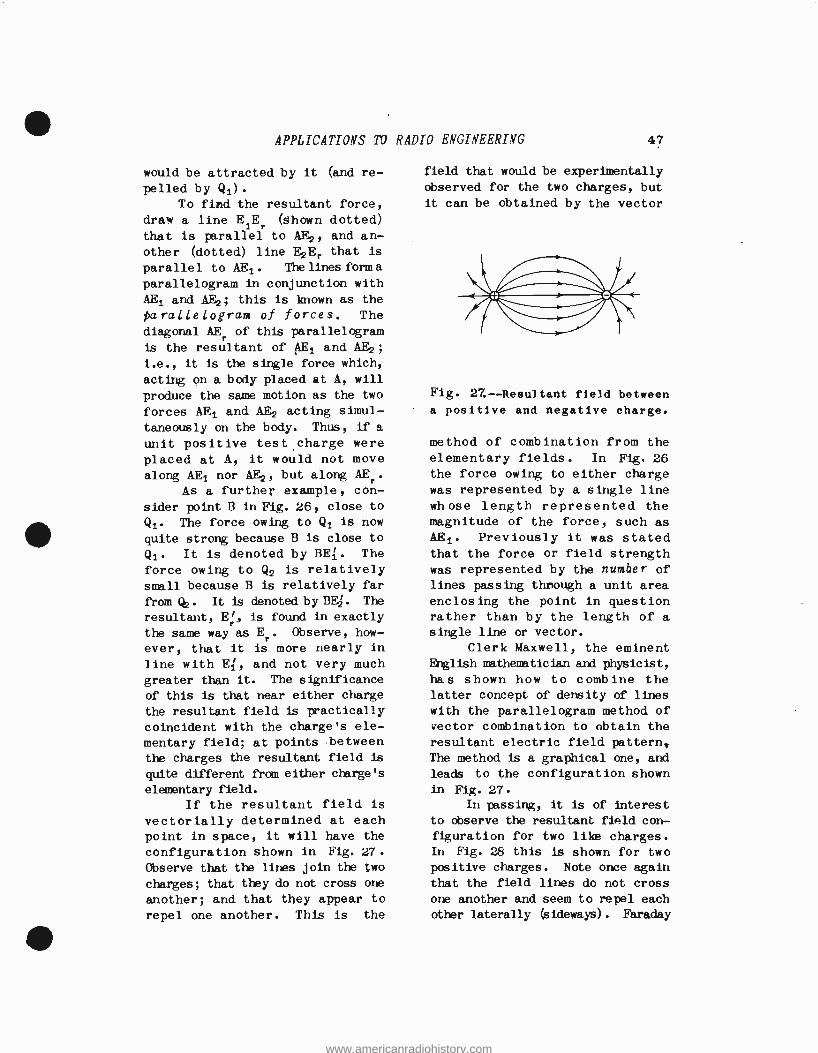
APPLICATIONS TO RADIO ENGINEERING 47
would be attracted by it (and re-
pelled by Q1). To find the resultant force,
draw a line E1Er (Shown dotted)
that is parallel to AF.2, and an-
other (dotted) line E2E, that is
parallel to AEl. Thelines form a
parallelogram in conjunction with AE1 and AE2; this is known as the
parallelogram of forces. The diagonal AEr of this parallelogram
is the resultant of AE1 and AE2 ;
i.e., it is the single force which,
acting on a body placed at A, will
produce the same motion as the two
forces AE1 and AE2 acting simul-
taneously on the body. Thus, if a
unit positive test charge were
placed at A, it would not move along AEI nor AE2f but along AEr.
As a further example, con-
sider point B in Fig. 26, close to
Q1. The force owing to Q1 is now
quite strong because B is close to
Q1. It is denoted by BE1. The
force owing to Q2 is relatively small because B is relatively far
from Qz . It is denoted by BE. 1. The
resultant, Er, is found in exactly
the same way as Er. Observe, how-
ever, that it is more nearly in
line with EI, and not very much greater than it. The significance
of this is that near either charge
the resultant field is practically
coincident with the charge's ele-
mentary field; at points between
the charges the resultant field is
quite different from either charge's
elementary field.
If the resultant field is vectorially determined at each point in space, it will have the
configuration shown in Fig. 27.
Observe that the lines join the two
charges; that they do not cross one
another; and that they appear to
repel one another. This is the
field that would be experimentally
observed for the two charges, but
it can be obtained by the vector
Fig. 27.-- Resultant field between
a positive and negative charge.
method of combination from the elementary fields. In Fig. 26 the force owing to either charge was represented by a single line whose length represented the magnitude of the force, such as
AE1. Previously it was stated that the force or field strength was represented by the number of lines passing through a unit area enclosing the point in question rather than by the length of a single line or vector.
Clerk Maxwell, the eminent English mathematician and physicist,
has shown how to combine the latter concept of density of lines
with the parallelogram method of vector combination to obtain the resultant electric field pattern, The method is a graphical one, and
leads to the configuration shown in Fig. 27.
In passing, it is of interest
to observe the resultant field con-
figuration for two like charges. In Fig. 28 this is shown for two positive charges. Note once again
that the field lines do not cross
one another and seem to repel each
other laterally (sideways). Faraday
www.americanradiohistory.com
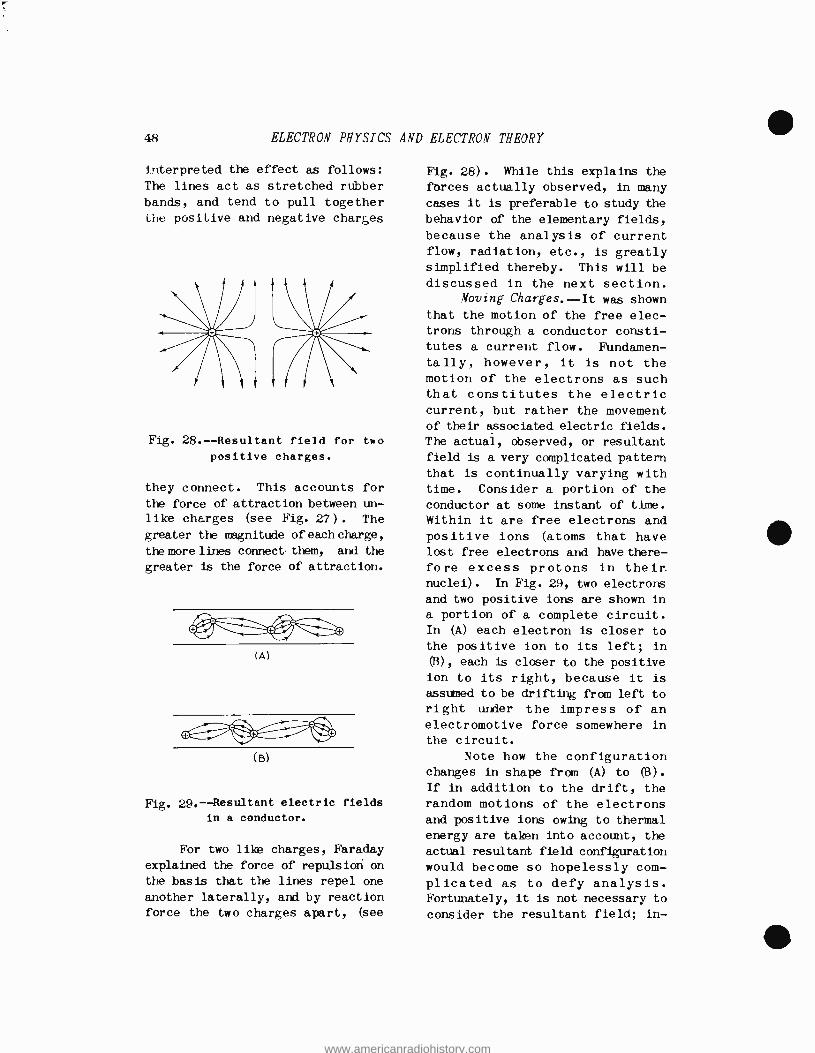
48 ELECTRON PHYSICS AND ELECTRON THEORY
interpreted the effect as follows:
The lines act as stretched rubber
bands, and tend to pull together the positive and negative charges
Fig. 28.-- Resultant field for two
positive charges.
they connect. This accounts for
the force of attraction between un- like charges (see Fig. 27) . The greater the magnitude of each charge,
the more lines connectthem, and the
greater is the force of attraction.
(A)
(B)
Fig. 29.-- Resultant electric fields
in a conductor.
For two like charges, Faraday
explained the force of repulsion on
the basis that the lines repel one
another laterally, and by reaction force the two charges apart, (see
Fig. 28). While this explains the forces actually observed, in many cases it is preferable to study the
behavior of the elementary fields, because the analysis of current flow, radiation, etc., is greatly simplified thereby. This will be discussed in the next section.
Moving Charges.--It was shown that the motion of the free elec- trons through a conductor consti- tutes a current flow. Fundamen- tally, however, it is not the motion of the electrons as such that constitutes the electric current, but rather the movement of their associated electric fields. The actual, observed, or resultant
field is a very complicated pattern
that is continually varying with time. Consider a portion of the conductor at some instant of time. Within it are free electrons and positive ions (atoms that have lost free electrons and have there- fore excess protons in their.
nuclei). In Fig. 29, two electrons
and two positive ions are shown in a portion of a complete circuit. In (A) each electron is closer to
the positive ion to its left; in
(B), each is closer to the positive
ion to its right, because it is
assumed to be drifting from left to
right under the impress of an electromotive force somewhere in
the circuit.
Note how the configuration changes in shape from (A) to 03).
If in addition to the drift, the random motions of the electrons and positive ions owing to thermal energy are taken into account, the
actual resultant field configuration
would become so hopelessly com- plicated as to defy analysis. Fortunately, it is not necessary to
consider the resultant field; in-
www.americanradiohistory.com
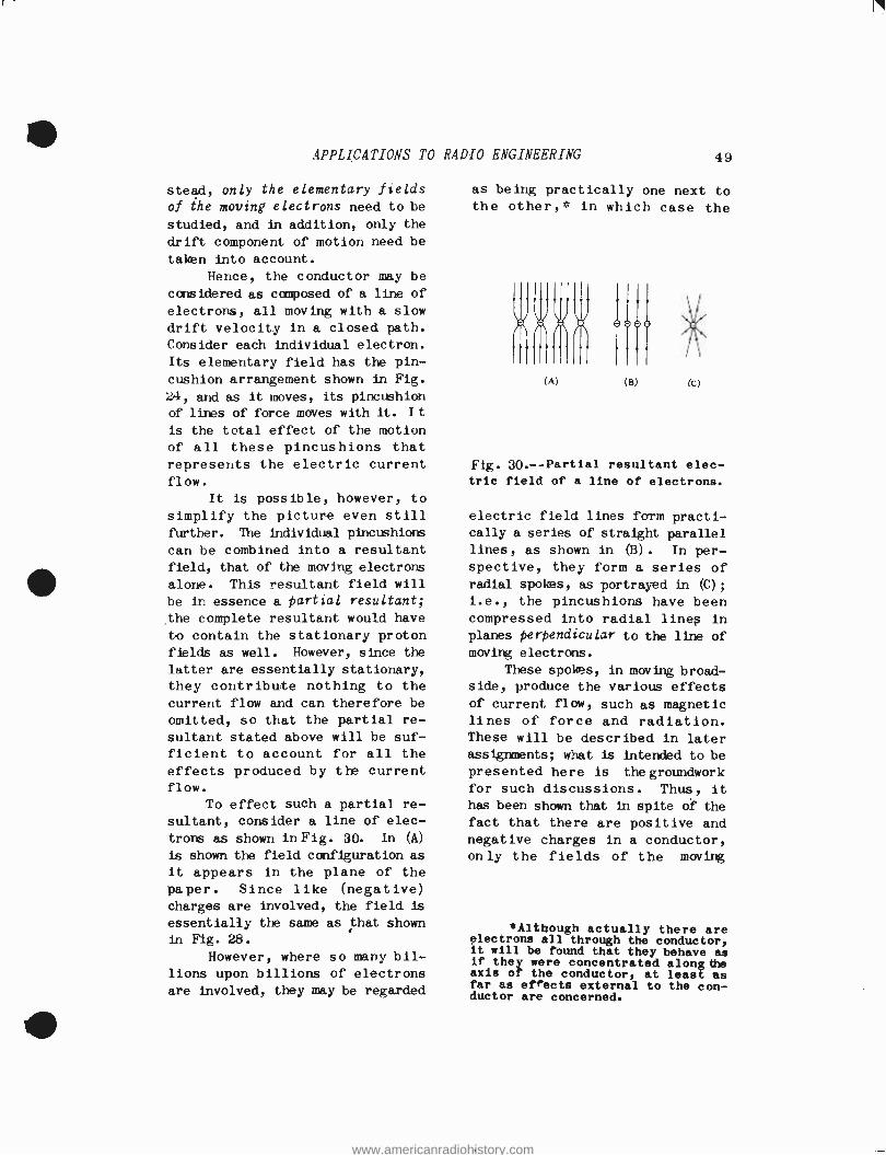
APPLICATIONS TO RADIO
stead, only the elementary fields
of the moving electrons need to be
studied, and in addition, only the
drift component of motion need be
taken into account.
Hence, the conductor may be
considered as composed of a line of
electrons, all moving with a slow
drift velocity in a closed path. Consider each individual electron.
Its elementary field has the pin-
cushion arrangement shown in Fig.
24, and as it moves, its pincushion
o f lines of force moves with it. I t
is the total effect of the motion
of all these pincushions that
represents the electric current flow.
It is possible, however, to
simplify the pictur -e even still further. The individual pincushions
can be combined into a resultant
field, that of the moving electrons
alone. This resultant field will
be in essence a partial resultant;
the complete resultant would have
to contain the stationary proton fields as well. However, since the
latter are essentially stationary, they contribute nothing to the
current flow and can therefore be
omitted, so that the partial re-
sultant stated above will be suf-
ficient to account for all the effects produced by the current flow.
To effect such a partial re-
sultant, consider a line of elec-
trons as shown in Fig. 30. In (A)
is shown the field configuration as
it appears in the plane of the
paper. Since like (negative) charges are involved, the field is
essentially the same as that shown in Fig. 28.
However, where so many bil- lions upon billions of electrons are involved, they may be regarded
ENGINEERING 49
as being practically one next to the other,* in which case the
(A) 'B) (C)
Fig. 30.- -partial resultant elec- tric field of a line of electrons.
electric field lines form practi- cally a series of straight parallel
lines, as shown in (B). In per- spective, they form a series of radial spokes, as portrayed in (C);
i.e., the pincushions have been compressed into radial line¢ in
planes perpendicular to the line of moving electrons.
These spokes, in moving broad- side, produce the various effects
of current flow, such as magnetic lines of force and radiation. These will be described in later assignments; what is intended to be presented here is the groundwork for such discussions. Thus, it
has been shown that in spite of the fact that there are positive and negative charges in a conductor, only the fields of the moving
*Although actually there are electrons all through the conductor, it will be found that they behave as if they were concentrated along the axis of the conductor, at least as far as effects external to the con- ductor are concerned.
www.americanradiohistory.com

50 MODERN THEORIES OF MATTER AND ELECTRICITY
charges need be considered, and in
the case of an ordinary metallic conductor, these fields can be combined into a partial resultant
field that is perpendicular to the
direction of motion of the charges.
RESUME
This concludes the assignment
on electron physics and theory. It
has been shown that the most im- portant fundamental particles of nature are the electron and the proton, and that a close combination
of these produces the neutron. An atom is in general a combination of
protons and neutrons forming a
nucleus, together with a group of electrons equal in number to that
of the protons, and rotating in certain shells or orbits about the
nucleus.
The chemical and ordinary electrical properties of the atoms
are explained in terms of the or-
bital electrons, particularly.those
in the outermost shell. Electrons
having but few electrons in the
outer shell are electro- positive or
metallic in nature, and exhibit the important property of electrical
conductivity owing to the presence
of free electrons in the crystal
lattice structure, Insulators are materials that
do not have an appreciable number
of free electrons, and hence do not exhibit electrical conductivity.
They can, however, exhibit momen-
tary current flows by the distor- tion of the electron orbits, and
this explains the charging current
that flows in the dielectric of a
condenser.
Free electrons can be emitted
from the surface of a metal by the action of heat, and this gives rise
to thermionic emission. Electrons
can also be dislodged from the material (even an insulator) by the action of radiant energy; this is known as photoelectric emission. Finally, electrons can be dislodged
from the atoms of a gas; this is
known as ionization.
As a concluding topic, elec- tric fields are analyzed, and it is
shown that the actual electric field observed between a system of
charges can be explained in terms of the elementary fields associ- ated with the individual charges.
ANSWERS TO EXERCISE PROBLEMS
1. 87.37 x 10⁻⁴ dynes repulsion.
2. 55.6 x 10⁻⁴ dynes repulsion.
3. 63.2 statcoulombs positive or
negative.
4. (A) 20.7 x 10 -8 ohms.
(B) .574 x 10-6 ohms.
5. 34 x 10-6 ohms.
6. 1.172 cm. long.
7. 162 ohms.
8. 0.0725 ohms.
9. 0.1236 ohms.
10. 1.27 x 107 cm. /sec.
www.americanradiohistory.com

V-7-77¢-3e
ELECTRON PHYSICS AND ELECTRON THEORY
EXAMINATION
1. (A) The/two most important elementary particles are the (electron, mesotron, neutron, proto'ii, photon, positron, neutrino) .
(B) An electron will attract a (proton, neutrpn, electron). ./
(C) A proton will repel a (neutron, prot n, electron).
(D) The proton has a mass that is /e9¢7 times that of an electron.
(E) The proton has a charge that is O' times that of an electron.
2. (A) A group of five electrons is separated from a group of eight protons by 2 X 10 -8 cm in free space.
(a) The force is one of (attraction, repulsion). _4-
(b) The magnitude of the force is -.Z.27 r /dynes. (Show all work.) o
Charpe .S ¢oc74tvzc s u 4.jc iv . z,3. RS" x/o Sf.Ca. 0144 6._ _Jr.)
o%c1 8xg%7uiU' 3/ G u/p OAarf 4,G'ß _ -- 3,85 X 86 x o a Z /.?3.áS xQ.34) / 4»,PS
x io -i c" R`
(B) The two groups are separated by a distance of 5 X 10 -8 cm. What is the magnitude of force between them?
_ 2 D /
www.americanradiohistory.com

ELECTRON PHYSICS AND ELECTRON THEORY
EXAMINATION, Page 2.
3. (A) A chemical reaction (alters, does not alter) the nuclei of the individual atoms.
(B) The nucleus, in general, is composed of %r d /Y-04/7-01$-
(C) How does the hydrogen nucleus differ from that of any other atom? /
was no reufrok), on /y a (orofoc,/
4. (A) There are the following number of orbital electrons in an atom of:
V (a) Radium: 88 / (b) Lithium
ó / (c) Thallium: (d) Iron
(B) The atomic number of carbon is 6.
(a) How may orbital electrons does it have? S,.,,C / III
(b) How many orbital shells does it have? lW o %wu
(c) How many electrons are there in each shell?
(d) It has a (positive, negative, dual) ence.
w
5. (A) Given two atoms: one has 92 protons and 146 neutrons; the other has 92 protons and 143 neutrons. re these atoms isotopes or isobars. /sofa rc s
(B) Can you identify these atoms? What are they?
Ll Ya f? ! li `vl CI ran ki4
6. Atoms of a gram of a certain material are split apart, and it is found that their mass is increased by O.Ó1 per cent. How much energy is absorbed by this increase in mass in the
,yi,áe ow'far
Ger/ ,se(/
www.americanradiohistory.com

- y/7it--
ELECTRON PHYSICS AND ELECTRON THEORY
EXAMINATION, Page 3.
6. process of splitting them apart, for the entire gram of the material? a
/4 _ ,oi jra. C = 71 /6
le
(B) A gram of another material is split apart, and in the process 5 x 10²⁰ ergs of energy are liberated. By how much is the mass decreased?
f, O/ . O 00 /
L
lI = ,t)y /Do C x/aJL
s' D . f,r4
7. (A) Conductors are substances that have (free electrons in their crystal lattice structure, the highest melting point, al] their orbital shells saturated, high vapor pressures.
(B) Thermal noise is owing to (thermionic emission, mechan- ical vibration of the material, crystalline structure of the material, random motion of the free e} trons).
8. (A) Electromotive force is the force produced by (a genera- tor, the coulomb action, radioactivity) that causes the (é_ lectrons_, protons, inoized atoms) to move j.n a metallic con- ductor, and is measured in (amperes, volts, coulombs, dynes, degrees Centigrade).
(B) The coulomb is the unit of (chargE; rate of flow of charge, potential between two condenser plates, force of repulsion between two electrons).
(C) Electrical current is measured in (amperes per second, ampere- seconds, ergs, amperes, kilovo
/lts, coulombs per sec-
ond, microamperes, millivolts, milliamperes, microfarads, mil]iwatts, megohms). (Check all correct answers.)
www.americanradiohistory.com
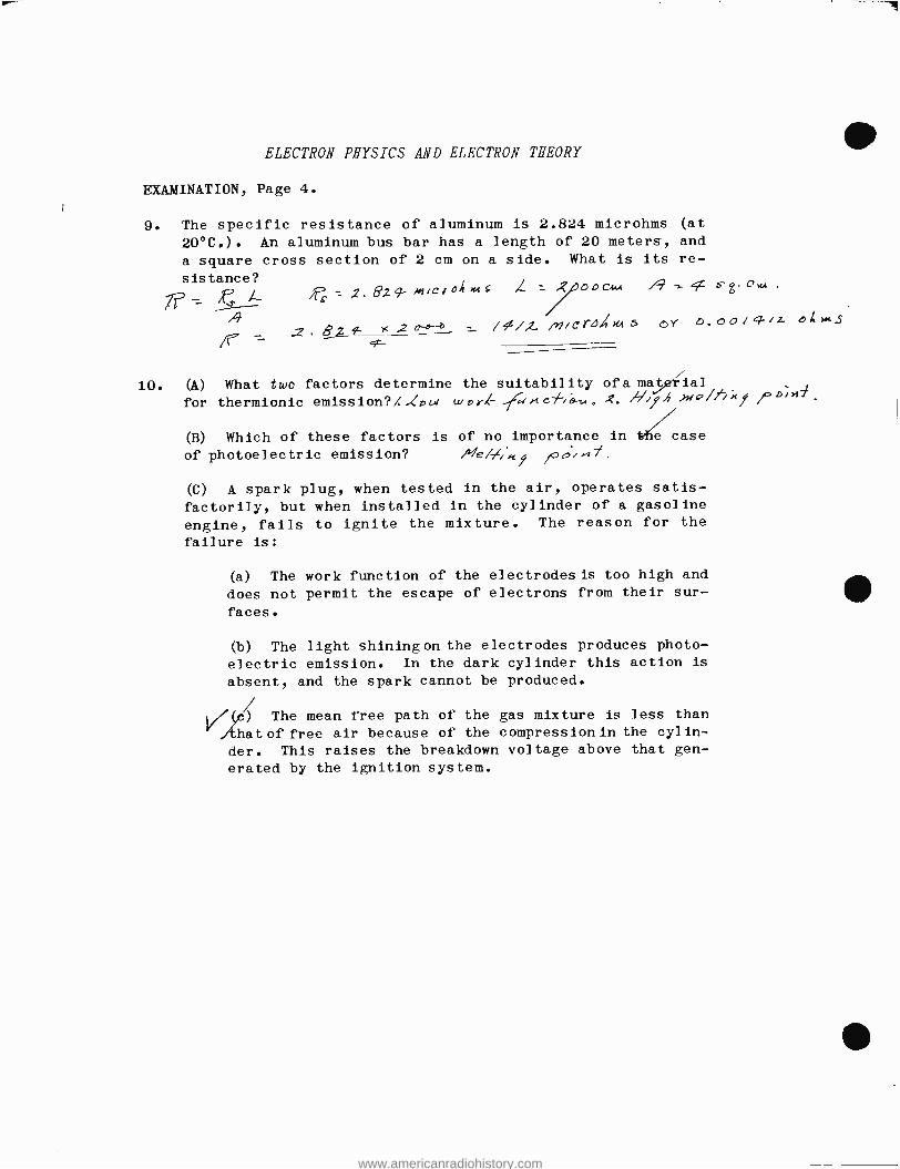
ELECTRON PHYSICS AND ELECTRON THEORY
EXAMINATION, Page 4.
9. The specific resistance of aluminum is 2.824 microhms (at
20 °C.). An aluminum bus bar has a length of 20 meters, and
a square cross section of 2 cm on a side. What is its re-
sistance?
A.L. = 2. 82 4- m 'e r o 1 MS ,L = 2 o o c44.4 /9 ¢ 4 z .
s- Ow4.
1 o-e-- /1/2. /rl i s is / m s o v b. 60 / ¢ /4 o h rK s
10. (A) What two factors determine the suitability of a marial for thermionic emission ?X.(DW _.7.4;+ cf.a,,,. /./ 7A v /fx% %b)>d' / (B) Which of these factors is of no importance in the case
of photoelectric emission? /Ve t/,K1 /0e>,-/./.
(C) A spark plug, when tested in the air, operates satis-
factorily, but when installed in the cylinder of a gasoline
engine, fails to ignite the mixture. The reason for the
failure is:
(a) The work function of the electrodes is too high and
does not permit the escape of electrons from their sur-
faces.
(b) The light shining on the electrodes produces photo-
electric emission. In the dark cylinder this action is
absent, and the spark cannot be produced.
1/(c) The mean free path of the gas mixture is less than
/that of free air because of the compressionin the cylin-
der. This raises the breakdown voltage above that gen-
erated by the ignition system.
www.americanradiohistory.com