Special Specification 595 Special Specification 7086 ...
70
7086 1 - 70 02-16 OTU Special Specification 7086 Sanitary Sewer 1. DESCRIPTION 1.1. Scope of Work Provide and install complete sanitary sewer construction and adjustments in conformity with the details shown on the plans, as described herein, in compliance with the Department’s Utility Accommodation Policy (UAP)(Title 43, T.A.C., Sections 21.31-21.55) or as directed. Reference specifications of the American Society for Testing and Materials (ASTM), American Water Works Association (AWWA) and American National Standards Institute (ANSI) will mean the latest standard in effect on the date of the proposal. 1.2. Definitions. Sanitary Sewer Main. Sanitary Sewer Main is defined as that portion of the sanitary sewer system which collects the wastewater from the service laterals, including stub outs from the nearest manhole, to the point of final destination. Service Lateral. Service Lateral is defined as that portion of the sanitary sewer system beginning at a customer property line or other establishment property line which is the point of origin of the wastewater being carried by the system to the sanitary sewer main, including the connection into the sanitary sewer main system. Point Repair. Point Repair is defines as the repair of a small length of pipe section of an existing sewer line which has deteriorated due to settlement or corrosion, or is falling, missing, crushed or broken, or has offset joints. Point repairs are to be completed before rehabilitation by trenchless methods between two adjacent manholes is initiated. Rehabilitation. Rehabilitation is defined as the rehabilitation of existing sanitary sewer mains by an approved trenchless method including Cured-In-Place-Pipe (CIPP) method or by sliplining with Centrifugally Cast Fiberglass Pipe (ASTM D-3262) or by sliplining with hollow Core I-Beam construction Closed Profile PVC Pipe (ASTM D-F794). Cured-In-Place-Pipe. This method consists of inverting a resin-impregnated flexible sewn felt tube into the original conduit by use of hydrostatic head. The resin is cured by circulating hot water within the tube. The Cured-In-Place-Pipe (CIPP) will be continuous and tight fitting. The work shall be completed with TxDot schedule. Contractors may, when appropriate, elect to use any material that is considered to be equal (i.e. A product that has structural physical properties that are equal or greater than those of the specified products), however, submittal to the design Engineer is required no later than 10 days prior to bid opening. Television Inspection. Television Inspection is defined as televising and videotaping of sewer lines utilizing a color closed circuit television inspection unit to determine the condition of the lines. Television Inspection is part of the acceptance requirements for new sewer lines. All new sewer mains will not carry flow until the Engineer and Inspector approve and accept the mains for service. Cleaning Manholes and Mains. Cleaning Manholes and Mains is defined as cleaning of existing sanitary sewer manholes and mains to facilitate the TV inspection and rehabilitation of the sanitary sewer mains.
Transcript of Special Specification 595 Special Specification 7086 ...

7086
1 - 70 02-16 OTU
Special Specification 595
Special Specification 7086
Sanitary Sewer
1. DESCRIPTION
1.1. Scope of Work
Provide and install complete sanitary sewer construction and adjustments in conformity with the details shown on the plans, as described herein, in compliance with the Department’s Utility Accommodation Policy (UAP)(Title 43, T.A.C., Sections 21.31-21.55) or as directed.
Reference specifications of the American Society for Testing and Materials (ASTM), American Water Works Association (AWWA) and American National Standards Institute (ANSI) will mean the latest standard in effect on the date of the proposal.
1.2. Definitions.
Sanitary Sewer Main. Sanitary Sewer Main is defined as that portion of the sanitary sewer system which collects the wastewater from the service laterals, including stub outs from the nearest manhole, to the point of final destination.
Service Lateral. Service Lateral is defined as that portion of the sanitary sewer system beginning at a customer property line or other establishment property line which is the point of origin of the wastewater being carried by the system to the sanitary sewer main, including the connection into the sanitary sewer main system.
Point Repair. Point Repair is defines as the repair of a small length of pipe section of an existing sewer line which has deteriorated due to settlement or corrosion, or is falling, missing, crushed or broken, or has offset joints. Point repairs are to be completed before rehabilitation by trenchless methods between two adjacent manholes is initiated.
Rehabilitation. Rehabilitation is defined as the rehabilitation of existing sanitary sewer mains by an approved trenchless method including Cured-In-Place-Pipe (CIPP) method or by sliplining with Centrifugally Cast Fiberglass Pipe (ASTM D-3262) or by sliplining with hollow Core I-Beam construction Closed Profile PVC Pipe (ASTM D-F794).
Cured-In-Place-Pipe. This method consists of inverting a resin-impregnated flexible sewn felt tube into the original conduit by use of hydrostatic head. The resin is cured by circulating hot water within the tube. The Cured-In-Place-Pipe (CIPP) will be continuous and tight fitting. The work shall be completed with TxDot schedule. Contractors may, when appropriate, elect to use any material that is considered to be equal (i.e. A product that has structural physical properties that are equal or greater than those of the specified products), however, submittal to the design Engineer is required no later than 10 days prior to bid opening.
Television Inspection. Television Inspection is defined as televising and videotaping of sewer lines utilizing a color closed circuit television inspection unit to determine the condition of the lines.
Television Inspection is part of the acceptance requirements for new sewer lines. All new sewer mains will not carry flow until the Engineer and Inspector approve and accept the mains for service.
Cleaning Manholes and Mains. Cleaning Manholes and Mains is defined as cleaning of existing sanitary sewer manholes and mains to facilitate the TV inspection and rehabilitation of the sanitary sewer mains.

7086
2 - 70 02-16 OTU
The designated sanitary sewer manhole sections and the manholes themselves shall be cleaned using mechanical, hydraulically propelled or high velocity sewer cleaning equipment. Debris generated by the cleaning process shall be removed from the manhole, transported and disposed of.
By-Pass Pumping. By-Pass Pumping is defined as by-pass pumping of sewage flow for the purpose of preventing interference with the rehabilitation of the sanitary sewer manholes and mains as well as providing reliable sewer service to the building being served.
Manhole Rehabilitation. Manhole Rehabilitation is defined as substrate rehabilitation for the purpose of eliminating infiltration, providing corrosion protection, repair of voids, and restoration of the structural integrity of the manhole by applying a monolithic fiber-reinforced structural and structurally enhanced cementitious liner to the wall and bench surfaces of brick, concrete, or any other masonry construction material.
Pipe Bursting or Crushing Replacement Process. The pipe bursting or crushing process is defined as the reconstruction of existing sanitary sewers by the simultaneous insertion (breaking and expanding the old pipe) of liner pipe within the bore of the existing pipe. The pipe bursting or crushing process involves the rehabilitation of deteriorated gravity sewer pipe by installing new pipe material within the enlarged bore created by the use of using s static, hydraulic, or pneumatic hammer “moling” device, suitably sized to break the existing pipe or by using a modified boring “knife” with a flared plug that crushes the existing sewer pipe. Forward progress of the “mole” or the “knife” may be aided by hydraulic equipment or other apparatus. Replacement pipe is either pulled or pushed into the bore. Sewer services are reconnected to the new pipe through small excavations from the surface. Sewage flows from the upstream line and from the services are pumped as required to prevent overflows and provide continual service. All excavations required for reconnecting and pumping service flows, entry pits, exit pits, obstruction removal, point repairs, among others, are to be kept to a minimum and all damage to surface and underground features, facilities, utilities and improvements are to be repaired.
Sliplining. Sliplining is accomplished by pulling or pushing liner pipe into existing sewers by use of mechanical or hydraulic equipment. Once in place, liner pipe is allowed time to normalize and is then cut to fit between the manholes. Manhole inverts and benches are re-worked and re-shaped. Existing sewers remain in operation during sliplining process, with sewage flow diverted around operations in progress.
2. MATERIALS
All materials furnished for this project will be new. A manufacturer’s certificate of compliance will be acceptable for quality control.
2.1. Sanitary Sewer Pipe
Materials for sanitary sewer pipe may be either rigid or flexible unless a specific type pipe is called for on the plans. Install materials as specified by the manufacturer.
2.1.1. Rigid Pipe
Ductile iron pipe shall, for the purpose of this specification, be known as rigid pipe. Ductile iron pipe and fittings are for use on force mains and shall not be allowed for use in gravity applications. All ductile iron pipe shall be provided with corrosion resistant linings
2.1.2. Flexible Pipe
Pipe consisting of materials other than those listed above.
Any flexible conduit having a deflection of the inside diameter greater than 5 percent after 30 days of installation as determined by a mandrel test, will not be accepted.

7086
3 - 70 02-16 OTU
Unless directed otherwise by the Engineer, a "GO, NO-GO" Deflection Testing Mandrel built in accordance with the detail drawing, as shown in the plans, and 30 TAC § 217, shall be furnished at the Contractor's expense and shall be used in testing pipe deflection for acceptance. Refer to “Air and Deflection testing,” section of this specification for more information about mandrel deflection testing.
Pipe stiffness is to be in accordance with ASTM 3034 SDR 26 [115 psi] or ASTM 2241 SDR 26 [160 psi].
At waterline crossings and where water and sewer mains are parallel and separation distance cannot be achieved as per 30 TAC§ 217.53, use extra stiff pipe SDR 26 PVC (ASTM D2241-09) with a pressure rating of at least 150 psi. This shall include all lateral piping as well.
All sanitary sewer piping shall pass the low pressure test, as described in 30 TAC § 217.57.
When the trench width is greater than the outside diameter of the pipe plus 2-ft. the pipe will be covered with Class B concrete, in accordance with Item 421, or as shown on the plans.
2.1.3. Concrete Pipe
Concrete pipe shall not be used.
2.1.4. Asbestos-Cement (AC) Pipe
AC pipe shall not be used. Refer to SAWS website for existing AC pipe and material handling.
2.1.5. Fiberglass Reinforced Sewer Pipe, Non-Pressure Type.
Fiberglass reinforced sewer pipe, non-pressure type, shall be a factory-formed conduit of polyester resin, continuous roving fiberglass and silica sand built up in laminates and shall conform to the requirements of ASTM D3262-11, including the appendix and subsequent specifications, and in accordance with SAWS’ material specifications. Depths shall comply with requirement of ASTM D3681-12.
Coupling Joints: Joints for pipe and fittings shall be confined compression rubber gasket bell and spigot type joints conforming to the material and performance requirements of ASTM D4161-01. Depths shall comply with requirement of ASTM D3681-12.
Fittings: Flanges, elbows, reducers, tees, wyes, laterals, and other fittings shall be capable of withstanding all operating conditions when installed. They may be contact molded or manufactured from mitered sections of pipe joined by glass-fiber reinforced overlays. For pipe diameters 15 inches or larger, lateral openings 6 inch or greater in size shall be made using PVC sewer saddles conforming to ASTM D2661-11 or service connections conforming to ASTM D3034-08, and approved by the Engineer.
Minimum pipe stiffness shall not be less than 115 psi for direct bury applications.
2.1.6. PMS PVC Pipe.
Polyvinyl Chloride (PVC) pipe will be made from class 12454-B materials as prescribed in ASTM D-1784. For pipes 4” to 15” in diameter PMS pipe, fittings and joints shall conform to ASTM D-3034 and elastomeric gasket joints meeting D-3212, and ASTM D-2241 and ASTM D-3139 where applicable, with the exception that solvent cement joints shall not be used. All pipe that is 18” to 27” in diameter shall meet requirements of ASTM F-679.
Water Main Crossings
Gravity or force main sewers constructed in the vicinity of water mains will comply with the requirements of the “Criteria for Domestic Wastewater Systems,” 30 TAC 217.53, as adopted by The Texas Commission on Environmental Quality, latest revision.

7086
4 - 70 02-16 OTU
Mechanical or compression joints, concrete jointing collars, or non-reinforced rubber adaptors shall be used only as approved by the Owner.
2.1.7. Pressure Pipe/Force Mains
Pipe shall be made from Class 12454-B, as defined in ASTM D1784-11. All pipe, fittings, and joints shall meet or exceed the requirements of ASTM D2241-09, with the exception that solvent cement joints shall not be used. The pressure rating, size, and pressure class shall be as shown in the contract documents. Pipe shall have an integral bell and gasket seal with the locked-in type gasket reinforced with a steel band or other rigid material conforming to ASTM F477-10. The joint shall comply with the requirements of ASTM D3139-98(2011). All required joint restraint shall be approved by the Engineer prior to the work being accepted. Pressure pipe/Force mains are required to have modified grade 5 material used as bedding. Pipes also shall be hydrostatically tested at a minimum of 100 psi after their construction to ensure proper construction.
2.1.8. Mechanical or compression joints
Mechanical or compression joints, concrete jointing collars, or non-reinforced rubber adaptors shall not be used unless as approved by the Engineer.
2.1.9. Ductile Iron Pipe and Fittings
Ductile iron pipe shall be centrifugally cast of 60-42-10 iron and shall conform to the requirements of the latest revision of ANSI Standard A21.51/American Water Works Association (AWWA) C151-09. Ductile iron pipe may be "thickness designed" in accordance with requirements of the latest revision of ANSI Standard A21.50/AWWA C150-08. Thickness design shall be based on standard laying conditions 4 or 5 in accordance with conditions at the site. Fittings for ductile iron pipe shall have not less than the thickness, class, or pressure rating specified for ductile iron pipe. Fittings shall be furnished with all necessary glands, gaskets, bolts, etc. as may be required to complete the joints.
Rubber gasket joints for mechanical joints or push on type joints shall conform to the requirements of ANSI Standard A21/AWWA C111-12.
All ductile iron pipe and fittings shall be cement mortar-lined or polyethylene-lined. The cement mortar lining shall be in accordance with ANSI A21.4/AWWA C104-08.
The polyethylene lining material for pipe and fitting shall be virgin polyethylene complying with ANSI/ASTM D1248-12, compounded with inert filler and with sufficient carbon black to resist ultraviolet rays during storage of the pipe and fittings. The polyethylene shall be bonded to the interior of the pipe or fitting by heat. Polyethylene lining in pipe and in fittings shall be 40 mils nominal thickness. Minimum lining thickness shall be 30 mils.
2.1.10. Concrete Steel Cylinder Pipe
Concrete Steel Cylinder Pipe shall not be used.
2.1.11. Pipe Testing.
All sanitary sewer pipe and fittings produced within the jurisdiction of the SAWS shall be tested by SAWS-approved laboratory method at the source of supply. All shipments of pipe not so tested shall be accompanied by a certificate of compliance to these specifications prepared by an independent testing laboratory and signed by a Texas licensed professional engineer.
2.1.12. Ductile Iron Pipe with Polybond Lining
The lining will be a composite lining utilizing a primer coating containing fusion bonded epoxy (FBE) and a surface coating containing fusion bonded polyethylene (FBP). The lining will be Polybond PLUS as

7086
5 - 70 02-16 OTU
manufactured by the American Cast Iron Pipe Company (Birmingham, AL) or an approved equal meeting the requirements of this specification. All lining application must be performed by the pipe manufacturer at the pipe manufacturer's facility. Linings applied by individuals other than the pipe manufacturer are unacceptable and will be rejected. Type and brand of lining shall be marked on each pipe or fitting.
Primer
The primer is to contain fusion bonded epoxy (FBE), which is applied in sufficient quantity to achieve a normal thickness of 5 mils for the pipe or fitting. The FBE material used in the primer formulation should be capable of meeting the following requirements.
TEST PARAMETER ASTM TEST TYPICAL VALUE
METHOD
Tensile Strength D-2370 9,300 psi
Compressive Strength D-695 11,600 psi
Ultimate Elongation D-2370 6.9 percent
Impact (1/8"x3"x3" panel)
5/8" diameter tup G-14 160 in.-lbs
Surface layer: The surface layer will be comprised of medium density modified fusion bonded polyethylene (FBP) meeting the requirements of ANSI/ASTM D1248 and compounded with an inert filler. The FBP will be formulated to be ultra-violet (UV) resistant for a minimum of three (3) years exposure. The color of the FBP is to have a light reflective value (LRV) of at least 40 percent to aid in the in-situ inspection of the pipeline with video equipment.
The fusion bonded polyethylene used in the surface coating material will be capable of meeting the following requirements:
TEST PARAMETER ASTM TEST TYPICAL VALUE
METHOD
Tensile Strength D-638 1,650 psi
Ultimate Elongation D-638 300 percent
Taber Abrasion Resistance D-4060 25.0 mg wt.
loss/1,000
cycles @ 1,000 gram load
Notched Izod Impact
@ 23 D-256 8.0 ft.-lbs/in.
(No break)
@ 60 C 6.1 ft.-lbs/in.

7086
6 - 70 02-16 OTU
(No break)
Brittleness Temperature D-746 -76 C
Thickness Requirements: Total thickness for the fusion bonded epoxy/fusion bonded polyethylene lining will be 60 mils nominal with a 50 mil minimum in the barrel of the pipe.
Lining Coverage: The fusion bonded epoxy/fusion bonded polyethylene lining will cover the interior surface of the pipe and fittings from the interior of the spigot end to a point sufficiently forward in the bell socket such that the Fastite gasket, in the assembled joint, seals over the end of the lining.
Joint Surface Coating: The joint surface coatings are to be comprised of a two component epoxy. The use of joint surface coatings containing coal tar is prohibited. Total thickness for the joint coating is to be 8 mils nominal.
The joint surface coating is to cover the spigot end across the end of the spigot bevel and extending over the outer surface of the spigot including the gasket sealing area. The joint surface coating is to also cover the socket from the face of the bell, through the gasket sealing area overlapping onto the edge of the FBE/FBP lining.
For each production lot, the lining is to be tested over 100 percent of the pipe barrel surface with a high voltage spark tester as recommended by ASTM Designation G-62 Method B of the latest version. The minimum test voltage is to be as determined by Method B, as described in the ASTM Designation Section 11.2.3, which is the recommended voltage for all linings with possible areas thicker than 41 mils:
V=1250 x T 1/2 where V = voltage and
"T" = thickness of lining in mils.
Example: V=1250 x 60 1/2 Minimum Voltage = 9,683 volts
If holidays are found in the lining by the above test at the manufacturing plant, the holiday is to be repaired per the lining manufacturer's recommendation.
The holiday detector is to be a commercially available detector available from holiday detection equipment manufacturers such as SPY, TINKER and RASOR, and ZORELCO.
Voltage Confirmation Test. To confirm that the above voltage is sufficient to detect holidays, the following voltage confirmation test should be performed for each shift or change in detector operator. The holiday detector should be set to the calculated minimum voltage shown above. A known holiday should be made in the lining of a randomly selected pipe using a small sharp pin. The operator should demonstrate that the holiday can be consistently and satisfactorily located at this voltage setting and detector wand speed. If the holiday is not detected at the calculated voltage, then the voltage should be slowly increased until the known holiday is consistently detected by the operator. This voltage should then become the minimum voltage at which all pipe linings are to be tested.
Testing Voltage Meter. The detector's voltage (and voltage meter) is to be tested once each day by a separate voltmeter and the results certified by the pipe manufacturer, to confirm the accuracy of the detector's voltage meter.
2.1.13. High Density Polyethylene (HDPE) Pipe and Fittings
All HDPE will have a minimum pressure rating of 200 psi and adimension ration of 9 (DR 9).
7086
7 - 70 02-16 OTU
Where standard ductile iron mechanical joint fittings are coupled to plain-end (square-cut) HDPE pipe, mechanical joint adapters must be used. Use Driscopipe Mechanical Joint Adapter (DIPS) Kit or approved equal.
Ductile Iron Bends and Fittings for HDPE Pipe. All bends and fittings will be furnished with the type of joint and end combinations specified. Mechanical joint fittings will be furnished complete with glands, gaskets and bolts. Flanged joint fittings will be furnished complete with gaskets and bolts. All bolts, glands and gaskets will be in accordance with AWWA Standard Specification C111.
All fittings will be furnished with standard outside coatings consisting of coal tar or asphalt base bituminous materials. Fittings will be cement mortar lined and sealed in conformity with AWWA Standard Specification C104.
Pipe Joint Restraint System for HDPE Pipe. Restraint devices will be used where ductile iron mechanical joint bell fittings are coupled to plain-end (square-cut) HDPE pipe, to prevent movement of pipe connections. The restraint system will have a minimum pressure rating of 250 psi. The restrainer must not be directionally sensitive.
Underwriter Laboratories and Factory Mutual certifications will be required on the restraint system. Each restraint device will be packaged individually and include installation instructions.
The pipe will be restrained by a split retainer band that will be cast ductile iron, meeting or exceeding ASTM A536 Grade 65-45-12. The inside face or contact surface of the bank will be of sufficient width to incorporate machined non-directionally sensitive serrations to grip the outside circumference of the pipe. The serrations will provide full (360°) contact and maintain pipe roundness and avoid any points of localized stress. The split bank casting will be designed to bottom-out before clamping forces (110 ft.-lb. minimum torque) can over-stress the pipe, but will provide full non-directionally sensitive restraint at the rated pressure.
Bolts and nuts used to attach the split retainer ring will comply with ANSI B 18.2/18.2.2, SAE Grade 5. Tee bolts, nuts and restraining rods will be fabricated from high strength, low-alloy steel in accordance with AWWA C111.
Restraint devices will be Uni-Flange Block Buster 1300C or approved equal.
Water Main Crossing. Where HDPE force main sewers are constructed in the vicinity of potable water mains, the requirements of the Texas Commission on Environmental Quality (30 TAC 217.53) will be met.
2.1.14. Steel Casing Pipe.
The component materials, manufacture and testing of all steel pipe will conform to AWWA Standard C-200 for “Steel Water Pipe 6-in. and Larger”. The specified pipe size will be the actual inside diameter of the pipe, special or fitting in inches. The diameter and wall thickness of all steel pipe will conform to those shown on the plans.
Pipe will be either Grade A or Grade B, conforming to ASTM Designation A-53.
Pipe ends will be beveled and suitable for field butt welding except as otherwise specified.
Pipe will receive a protective coating conforming to AWWA Standard C-203, “Coal-Tar Protective Coatings and Linings for Steel Pipelines – Enamel and Tape Hot Applied”.
Pipe length will be nominal 40 ft. lengths except for specials or as otherwise specified on the plans. Standard and specials will be within 1/16-in. (plus or minus) of the specified or theoretical lengths.
2.1.15. Stainless Steel Casing Spacer/Insulators

7086
8 - 70 02-16 OTU
This section covers casing spacers for use in water supply service. Casing spacers are used to facilitate installing a water pipe inside a casing pipe or tunnel. Casing spacers shall consist of two or more segments of circular steel that bolt together forming a shell around the carrier pipe(s). Casing spacers should protect the carrier pipe and any protective coating or wrapping from damage during the installation, and properly support and electrically isolate the carrier pipe(s) within the casing or tunnel. On occasion multiple carrier pipes may be installed in one casing or tunnel.
2.1.15.1. General Requirements
The San Antonio Water System (SAWS) reserves the right to limit the purchase of casing spacers from the manufacturers and to the models specified as shown in paragraph 4, providing such casing spacers conform to the provisions contained herein.
Casing spacers shall be eight inches (8”) long for carrier pipes up to 16- inch diameters and twelve inches (12”) long for larger carrier pipe sizes. Manufacturer’s approval in writing shall be required for installations exceeding 300 ft. in length, carrier pipes in excess of 48- inch diameter or multiple carrier pipes in one casing or tunnel.
Casing spacers shall have a minimum 14-gauge steel band and 10 gauge steel riser when required. The band, risers and connecting studs shall be welded and cleaned at the factory before the application of a fluidized bed fusion bonded PVC coating. Stainless steel (type 304) casing spacer is an acceptable alternative.
The fluidized bed fusion bonded PVC coating shall be between 10-16 mils thickness. The PVC coating shall provide good resistance to acids and alkalize and excellent resistance under ASTM B117 salt spray tests. The coating shall have a minimum 1380volts/mil per ASTM D149-61 short time 0.010” test and a Durometer-shore A@ (10 sec) of 80 per ASTM D1706-61T. Epoxy coatings are not an acceptable alternative.
The spacers shall have a flexible PVC liner of 0.09-inch thickness with Durometer “A” 85-90 hardness and a minimum 58,000- volt dielectric strength (60,000-volt minimum Surge Test.) Moisture absorption shall not exceed 1%.
The runners shall be of high pressure molded glass reinforced polyester with a minimum compressive strength of 18,000 psi per ASTM D695, flexural strength of 25, 300 psi per ASTM D790, tensile strength of 17,600 psi per ASTM D638 and Rockwell hardness (M) of 90 per ASTM D785. The riser shall be designed and fabricated to place the runner (skid) in full contact with the inside surface of the casing pipe. This evenly distributes the load force to all support members. The ends of all runners shall be shaped to resist hanging or sticking inside casing during installation of the carrier pipe. Polyethylene runners are not acceptable.
Runners shall be a minimum of 1.0 inch in width and a minimum of 7 inches long for carrier pipes up to 16”, and a minimum of 2.0 inches in width and 11 inches long for larger carrier pipes. Bolts on runners are not acceptable. The runners shall be attached to the band or riser by 3/8 the wearing surface on the runner. The recess shall be filled with a corrosion inhibiting filler. There shall be four runners per casing spacer for carrier pipes up to 12” diameter, six runners for 14” through 36” and eight or more runners for carrier pipes over 36” diameter. Number of bottom runners shall be multiples of two. Number of top runners shall be multiples of two.
The band section shall be bolted together with 5/16” cadmium-plated studs, nuts and washers. There shall be six sets per 8” long casing spacer and eight sets per 12” long spacer. Stainless steel casing spacers shall be furnished with stainless steel studs, nuts and washers.
Casing spacers shall have ample riser height to limit vertical movement of the carrier pipe in the casing. A minimum of 1” to 2” clearance shall be provided between the top runner and the ID of the casing or tunnel.
Continuous operating temperatures for the PVC Coated Casing Spacers should not exceed 150°F. Stainless steel casing shall be used in applications where continuous operating temperatures exceed 150°F.

7086
9 - 70 02-16 OTU
Unless noted otherwise, casing spacers shall be required on all carrier pipes installed in casing or tunnel applications.
2.1.15.2. Quality Assurance
All casing spacers are to be manufactured in accordance to NACE International Recommend Practice RP 0286-97 (Isolation Spacers.) Each casing spacer shall be manufactured in the USA at a facility that has a Registered ISO 9002 Quality Management System or be in the process of achieving this certification by March 2005. Non-compliance to this registered commercial quality system requirement by March 2005 will result in removal of the manufacturer’s product from paragraph 4 approved manufacturers.
If on receipt of casing spacers they are found to be non-compliant, the manufacturer shall replace the defective casing spacer with a casing spacer that meets the San Antonio Water System’s specifications, at no charge to San Antonio Water System.
If San Antonio Water System audits, product inspection and performance data review in accordance to these specifications determine excessive casing spacer Noncompliance, the manufacturer will be subject to removal by the Products Standard Committee. Copy of the current ISO 9002 registration (or written documentation of being “in the process of achieving ISO registration,” prior to March 2005) shall be provided with material submittal.
2.1.16. Water Main Crossings
Gravity or force main sewers constructed in the vicinity of water mains will comply with the requirements of the “Criteria for Domestic Wastewater Systems,” 30 TAC 217.53, as adopted by The Texas Commission on Environmental Quality, latest revision.
2.2. Manholes
Material for manholes will conform to the requirements of Item 465, “Manholes and Inlets”, as described below and as shown on the plans.
All material and construction work shall be in accordance with current Texas Commission on Environmental Quality (TCEQ) rules to include: Design Criteria for Sewage Systems (30 TCEQ § 217). All constructed manholes shall be watertight. Manhole covers may be either watertight or water resistant, depending on their specific location. Every manhole cover located in an identified 100-year floodplain, or in the Edwards Aquifer Recharge Zone, shall be watertight. Sewer manhole ring and cover castings shall meet the current requirements of AASHTO Designation M306-10.
Unless otherwise shown in the contract documents or approved by the Engineer, standard sanitary sewer manholes shall be constructed with influent and effluent piping less than or equal to 24 inches in diameter with precast reinforced concrete manhole sections. A standard sanitary sewer manhole shall be a single entrance cylindrical structure, having a minimum internal diameter of 4feet between the cone and base sections. The base of the structure shall include the load bearing portion beneath and exterior of the structure, invert channels and the fill or bench portions adjacent to the lower sewer pipes within the structure. The maximum vertical height of the diameter adjustment section or cone shall be 36 inches. Adjustment or throat rings may be used for final elevation adjustment of the manhole ring and cover. Concrete encasement of the manhole’s ring shall be as shown in the plans. Specifically, they shall attach the ring and cover to the diameter adjustment section or cone. Manholes which differ from the above description shall be identified as “Manhole Structures"
An internal drop manhole shall be required, when sewer lines enter a manhole more than 24 inches above the manhole invert, while an external drop manhole shall be provided for a sewer entering a manhole more than 30 inches above the invert. Both conditions will require prior approval by the Engineer.
2.2.1.1. Manhole Structures

7086
10 - 70 02-16 OTU
Cast in place concrete structures or pre-cast concrete structures, as detailed on the plans, will be installed where any pipe intercepted is larger than 24-in. in diameter.
2.2.1.2. Precast Reinforced Concrete Manhole Sections
Precast reinforced concrete manhole sections shall conform to the requirements of ASTM Designation C478-12a.
2.2.1.3. Manhole Ring and Cover
The standard manhole ring and cover shall be ductile iron and manufactured to the dimensions shown on the plans. The ring and cover shall be hinged. Lifting slots cast into the covers shall be provided for lifting purposes. A water-resistant (cam lock) ring and cover shall be used in areas of minimal infiltration potential to allow venting. A watertight (bolt down) ring and cover must be used in areas of high infiltration potential, such as in the Edward’s Aquifer Recharge Zone, an identified 100-year floodplain, or as otherwise directed by the Engineer.
The nominal cover diameter shall be 32 inches, with a 30 inch clear opening, as required by TCEQ. Rings shall have a minimum of four 1 inch holes/slots for anchoring purposes. Rings shall be a minimum of 4-1/2 inches in height, or as otherwise accepted by the Engineer. Slots for embedment/lightening are not allowed in ring flanges.
Water-resistant Rings and Covers: Rings and covers shall have two hinges for added stability. The hinge shall have a drain to allow for proper debris and foreign object removal. Prior to acceptance of the work, a stainless steel keyed “cam” lock shall be provided by the Contractor to the Inspector. When the key is inserted in the cam, it shall remain in the lid while the cam is in the open (unlocked) position. When in the closed (locked) position, the key can be removed. When not in use, the cam lock key hole shall be covered with a plastic plug to prevent infiltration of debris. The cover shall positively lock at 90° to prevent accidental closure and open fully to 120°. The cover shall also include a single multi-tool lifting slot adjacent to the edge of the cover to facilitate opening/lifting/prying once it is unlocked. Covers shall be provided with a continuous vulcanized (one piece) EPDM gasket with a shore durometer of 70 ±5 permanently attached to the cover.
Watertight Rings and Covers: Rings and covers shall be the same as above for water-resistant version, except the covers shall be bolted to the ring instead of secured with the cam lock mechanism. No vent hole(s) shall be provided. A minimum of four 1/2 inch diameter, stainless steel, hex head bolts shall be provided for each cover. The 4 bolt holes in the covers shall be evenly spaced and provided with a minimum 1-½ inch diameter counter sink for the bolt heads. On the fastened and bolted position, the bolt heads shall not extend above the surface or the cover. Washers of a size and material as approved by the Engineer shall be provided for the bolts to insure air and water tightness.
The finished ring and cover shall have the bearing surfaces machined ground and sets of rings and covers shall be marked in such a way that they can be matched for assembly in the field. All covers shall have the words "SAN ANTONIO WATER SYSTEM Sanitary Sewer" cast thereon.
Ring and cover shall have the approved foundry’s name, part number, country of origin preceded by “Made in” (example: MADE IN USA) in compliance with the country of origin law of 1984, and production date (example: mm/dd/yy) for tracking purposes. Each casting must be marked with DI and ASTM A536 or A536 80-55-06 to verify the materials used. Castings without proper markings shall be rejected.
2.2.1.4. Throat Rings
Throat rings shall be made of either HDPE or reinforced concrete and have a maximum thickness of 2 inches. The internal diameter shall match that of the ring and cover’s opening. Concrete shall conform to the provisions of Concrete (Class “A”), Item No. 421 Hydraulic Cement Concrete. If concrete throat rings are to be utilized, they must be used in conjunction with a UV stabilized polyethylene liner. I/I barrier must meet the following ASTM standards: ASTM D790/1505 Density of Polyethylene Materials, ASTM D1238-10 Melt Flow index, ASTM 638-10 Tensile Strength @ Yield (50mm/mm), ASTM 790-10 Flexural Modulus, ASTM 648-07

7086
11 - 70 02-16 OTU
Heat Deflection Temperature @IGEPAL, ASTM 1693-12 EsCR, 100% IGEPAL/10% IGEPAL. A minimum of two and a maximum of four throat rings may be used at each manhole installed.
2.2.1.5. Coating
All manholes shall be watertight and coated with a SAWS approved sewer coating. Prior to coating, all manholes shall be vacuum tested, and approved. For existing and rehabilitated manholes, apply a combination of both products with the cementitious coating first, followed by the epoxy coating. Kerneos SewperCoat 2000 HS regular, applied at the required one inch thick application, is the only product approved which does not require a subsequent epoxy coating. New manholes installed do not require the cementitious coating. Cementitious liner thickness shall be measured by the penetration method at locations specified by SAWS prior to the final setting of the material. Approved materials are as follows:
Cementitious coating: With required one inch thick application:
Permaform CR-5000;
Strong - Seal MS-2C;
Standard Cement Material Inc. Reliner;
Quadex Aluminaliner;
ConShield Biotech Armor.
Epoxy coating: With specified thickness application:
Raven 405 Series High Build Epoxy Liner: Required thickness – 125 mils;
Spray Wall polyurethane System: Required thickness – 125 mils;
Carboline “Plasite 4500” System: Required thickness – 125 mils.
2.3. Manhole Rehabilitation
The Contractor shall submit descriptive information including technical data sheet and ASTM test results on each product proposed indicating that the product conforms to and is suitable for its intended use per the specifications. The Contractor may, when appropriate, elect to use any materials that is considered to be equal (i.e. a product that had structural and physical properties that are equal to or greater than those of the specified product). However, submittal to the Engineer is required no later than 10 days prior to bid opening. Should the Contractor elect to use any materials other than those contained herein, they should be completely and clearly identified when making the product submittal. This will expedite the review process, in which the Engineer decides whether the products meet the Contract requirements and the specific use foreseen. The purpose of this process is to expedite review of Contractor product submittals.
Concrete shall conform to Item 420, “Concrete Structures”.
Mortar shall be composed of 1 part Portland cement,1 part masonry cement (or 1/4 part hydrated lime), and masonry sand equal to 2.5 to 3 times the sum of the volumes of the cements and lime used.
Unless otherwise specified, all grouting shall be done with non-shrinking grout.
Reinforcing steel shall conform to the requirements of Item 440, ‘Reinforcing Steel”.
Replacement brick for ring adjustment courses shall be of first quality, sound, kiln fired, new unbroken brick.
Structural or High Sulfate resistant lining for rehabilitation shall be Raven 405 Series high build Epoxy Liner minimum 200 mils thick, Spray Wall polyurethane system minimum 250 mils thick or equal (i.e. a product that has structural and physical properties that are equal to or greater than those of the specified product).
2.4. Cleaning Manholes and Mains
2.4.1. Preparation.

7086
12 - 70 02-16 OTU
The Contractor shall be required to have all materials, equipment and labor necessary to complete the cleaning of the sanitary sewer main and manholes on the job site prior to isolating the sewer manhole or main segment and beginning the cleaning process.
2.4.2. Cleaning Materials.
Use only cleaning materials recommended by manufacturer of surface to be cleaned. Use each type of cleaning material on only those surfaces recommended by the cleaning materials manufacturer. Use only materials which will not create hazards to health or property or affect treatment plant process.
2.5. Concrete
All concrete is to meet the requirements of Item 421, “Hydraulic Cement Concrete”. Unless otherwise shown on the plans or required by this specification, all concrete will be Class A.
2.6. Mortar
Mortar shall be composed of 1 part Portland Cement, 2 parts sand and sufficient water to produce a workable mixture. When used to plaster manholes, it may be composed of 1 part cement to 3 parts sand. Lime up to 10% may be used. It will have a consistency such that it can be easily handled and spread.
2.7. Reinforcing Steel
Reinforcing steel and the placing thereof is to conform to the requirements of Item 440, “Reinforcing Steel”, except where welded wire is called for on the plans, the material will be welded wire flat sheets meeting A.S.T.M. A-185. Welded wire rolls will not be used.
2.8. Cement Stabilized Backfill
Cement stabilized backfill is to be in accordance with Item 400, “Excavation and Backfill for Structures”.
2.9. Flowable Backfill
When indicated on the plans, the trench is to be backfilled to the dimensions shown with flowable backfill. The flowable backfill with fly ash will be Mix Design Type B in accordance with Item 401, “Flowable Backfill”, or an acceptable mix as approved.
2.10. Grout
When shown on the plans for various applications, the grout is to be a cement/sand/water mixture as approved. It will have a consistency such that it will flow into and completely fill all voids.
2.11. Sewer Main Television Inspection
The Contractor shall furnish all labor, materials, equipment, and incidentals to provide the televising and a NASSCO-(PACP) standard video, recorded in MPEG-1 format and written to DVD video of sewer lines and manholes utilizing a color, closed-circuit television inspection unit to determine their condition.
The Contractor shall provide a line diagram area sketch and written log for each completed segment of DVD sewer main describing the section being televised, flow and camera direction, position of service connections, description and location of failures, pipe condition, weather conditions, and other significant observations.
Television inspection shall be done one manhole section at a time. Also the flow in the section being televised shall be bypassed if the line is in service and the flow exceeds 25% of the internal pipe diameter.

7086
13 - 70 02-16 OTU
When the depth of flow at the upstream manhole of the manhole section being worked is above the maximum allowable for television inspection, the flow shall be reduced to allowable levels by temporarily plugging or blocking the flow or bypass pumping, as approved by Inspector.
The Contractor shall not be allowed to float the camera. There may be occasions during the televised inspection of a manhole section when the camera will be unable to pass an obstruction. At that time, and prior to proceeding, the Contractor shall contact the Inspector. If the length of sewer line cannot be televised because of obstructions, the Contractor shall clean the system as is necessary. If, in the opinion of the Inspector, the obstruction is attributed to a collapsed main or pipe deflection, televising shall be suspended, payment shall be made based on the actual televised length, and the remaining televising of the sewer line shall be continued upon successful correction of the blockage by the Contractor at his expense. No additional payment shall be made for additional setups required due to obstructions encountered during televising.
Log Formats. Each DVD will be permanently labeled with the following:
Project Name,
Date Televised,
Station to Station Location and Size of Sanitary Sewer,
Street/Easement Location,
Name of Contractor,
Date DVD Submitted, and
DVD Numbers.
Videotape Quality. If the Contractor produces a DVD of poor quality that the Engineer is unable to evaluate the condition of the sanitary sewer main or locate the sanitary sewer service lateral connections, the Contractor will be required to re-televise the sanitary sewer main and provide a new DVD of good quality at no additional cost.
Equipment Required For TV Inspections. The Contractor will be required to have all materials, equipment and labor necessary to complete all videotaping on job site prior to isolating the sewer manhole segment and beginning videotaping operations. A camera with rotating or panning lens capabilities is required. The television inspection equipment shall have an accurate footage counter which displays on the monitor the exact distance of the camera from the center of the starting manhole. A camera with rotating and panning lens capabilities is required. The camera height shall be centered in the conduit being televised. The speed of the camera through the conduit shall not exceed 40 feet per minute.
The television unit shall also have the capability of displaying in color, on DVD, pipe inspection observations such as pipe defects, sags, points of root intrusion, offset joints, service connection locations, and any other relevant physical attributes.
DVD Logs. The Contractor is to provide, with each completed DVD, a TV inspection report which is a written log of all pipe defects, sags, points of root intrusion, offset points, service connection locations and condition recorded on a footage basis. This log is to also denote the section being televised, flow and camera direction, position of taps or failures, pipe condition and weather conditions.
2.12. Polyethylene Wrapping Material
Polyethylene wrapping material will be used to encapsulate all ductile and cast-iron fittings.
2.12.1. General Requirements
Polyethylene wrapping for ductile and cast-iron fittings will consist of a 4 mil tubular section of cross-laminated high-density polyethylene, which has a high dielectric and tensile strength, for use in insulating cast-iron and ductile-iron pipe from the electrolytic action encountered in highly active soils. All iron pipe, fittings, and accessories shall be wrapped with edges overlapped and taped securely with duct tape to

7086
14 - 70 02-16 OTU
provide a continuous wrap to prevent contact between the pipe and the surrounding backfill. Repair all punctures with duct tape to restore the continuous protection before backfilling.
Polyethylene wrapping is to consist of opaque cross-laminated high-density polyethylene sheet continuously thermally bonded to form a tubular section. The tubes may be supplied in bulk length on rolls or in individual pre-cut lengths. See Table 21 for size and length chart, in accordance with AWWA C-105 (Table 1) for minimum requirements. When supplied in specific pipe lengths, the tubes are to contain a minimum of 4-ft. over the actual pipe length to allow for overlap.
The polyvinyl sheet of film for the tubular wrapping is to be of virgin resins meeting raw and physical properties of ASTM D-1248 and AWWA C-105, latest edition. The material is to be 4 mil cross-laminated high-density polyethylene of uniform film thickness and be free of imperfections such as pin holes, etc., after being thermally seamed into tubular form. The finished product will have a nominal thickness of 4 mils, with tolerances of minus ten percent.
The material is to have no volatile constituents, the loss of which may affect ductility. The material is also to have the following properties:
Mechanical: The polyethylene film is to have a tensile strength per latest ASTM D-882 test, of 6300 psi
min. The film is to have an elongation of not less than 100% of the test strip per latest ASTM D-882
test. The film is to have an impact resistance 800 gram min per (ASTM D-1709 Method B). The film is
to have a propagation tear resistance of 250 gf minimum in machine and transverse direction (ASTM
D1922).
Dielectric: The film is to have a dielectric strength of 800 volts per mil thickness per ASTM D-149.
Inspection and Certification by Manufacturer:
Quality control and inspection. The manufacturer shall establish the necessary quality control and
inspection practice to ensure compliance with this standard.
Manufacturer’s statement. The manufacturer shall, provide a sworn statement on each lot purchased
that the inspection and all applicable material requirements of Section 4.1 have been met and that all
results comply with the requirements of this standard.
Freedom from defects. All polyethylene film shall be clean, sound, and without defects that could impair
service.
2.12.2. Marking Requirements
The polyethylene film supplied shall be clearly marked, at a minimum of every 2-ft along its length, containing the following information.
Manufacturer’s name or trademark
Year of manufacture
ANSI/AWWA C-105/A21.5
Minimum film thickness and material type.
Applicable range of nominal pipe diameter size(s).
Warning-Corrosion Protection-Repair any Damage.
The San Antonio Water System may at no cost to the Contractor, subject random testing by an independent laboratory for compliance with this Specification. Any visible defect of failure to meet the quality standards herein will be grounds for rejecting the entire order.
7086
15 - 70 02-16 OTU
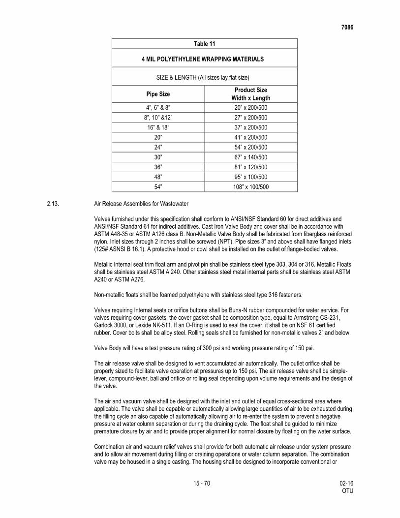
Table 11
4 MIL POLYETHYLENE WRAPPING MATERIALS
SIZE & LENGTH (All sizes lay flat size)
Pipe Size Product Size
Width x Length
4”, 6” & 8” 20” x 200/500
8”, 10” &12” 27” x 200/500
16” & 18” 37” x 200/500
20” 41” x 200/500
24” 54” x 200/500
30” 67” x 140/500
36” 81” x 120/500
48” 95” x 100/500
54” 108” x 100/500
2.13. Air Release Assemblies for Wastewater
Valves furnished under this specification shall conform to ANSI/NSF Standard 60 for direct additives and ANSI/NSF Standard 61 for indirect additives. Cast Iron Valve Body and cover shall be in accordance with ASTM A48-35 or ASTM A126 class B. Non-Metallic Valve Body shall be fabricated from fiberglass reinforced nylon. Inlet sizes through 2 inches shall be screwed (NPT). Pipe sizes 3” and above shall have flanged inlets (125# ASNSI B 16.1). A protective hood or cowl shall be installed on the outlet of flange-bodied valves.
Metallic Internal seat trim float arm and pivot pin shall be stainless steel type 303, 304 or 316. Metallic Floats shall be stainless steel ASTM A 240. Other stainless steel metal internal parts shall be stainless steel ASTM A240 or ASTM A276.
Non-metallic floats shall be foamed polyethylene with stainless steel type 316 fasteners.
Valves requiring Internal seats or orifice buttons shall be Buna-N rubber compounded for water service. For valves requiring cover gaskets, the cover gasket shall be composition type, equal to Armstrong CS-231, Garlock 3000, or Lexide NK-511. If an O-Ring is used to seal the cover, it shall be on NSF 61 certified rubber. Cover bolts shall be alloy steel. Rolling seals shall be furnished for non-metallic valves 2” and below.
Valve Body will have a test pressure rating of 300 psi and working pressure rating of 150 psi.
The air release valve shall be designed to vent accumulated air automatically. The outlet orifice shall be properly sized to facilitate valve operation at pressures up to 150 psi. The air release valve shall be simple-lever, compound-lever, ball and orifice or rolling seal depending upon volume requirements and the design of the valve.
The air and vacuum valve shall be designed with the inlet and outlet of equal cross-sectional area where applicable. The valve shall be capable or automatically allowing large quantities of air to be exhausted during the filling cycle an also capable of automatically allowing air to re-enter the system to prevent a negative pressure at water column separation or during the draining cycle. The float shall be guided to minimize premature closure by air and to provide proper alignment for normal closure by floating on the water surface.
Combination air and vacuum relief valves shall provide for both automatic air release under system pressure and to allow air movement during filling or draining operations or water column separation. The combination valve may be housed in a single casting. The housing shall be designed to incorporate conventional or
7086
16 - 70 02-16 OTU
kinetic flow principles to properly vent the air without premature closure. Flanged sized (4 inch and larger) may be furnished in a dual housing. When dual casings are used a bronze manual isolation valve shall be installed if indicated by the manufacturer. This will allow the air release valve to be serviced when the system is under pressure. Field service of the valve may also be performed by closing the isolation valve between the air valve and the pipe connection.
The San Antonio Water System may, at no cost to the manufacturer, subject random valves to testing by an independent laboratory for compliance with these standards. Any visible defect or failures to meet the quality standards herein will be grounds for rejecting the entire order.
The manufacturers shall provide certification that products furnished under this specification are manufactured in an ISO 9001 certified facility or documentation from an accredited facility that ISO 9001 certification is in process.
2.14. Rehabilitation of Lines.
2.14.1. Point Repair Pipe
Pipe Material used for repairs shall be in accordance with Section 2.1 “Sanitary Sewer Pipe”. If point repair is located at a service connection, use a full-bodied fitting for the service connection. No field fabrication of fittings allowed.
Joint Material. Use flexible adapters secured with ½ inch stainless steel bands, as manufactured by Fernco, or approved equal. All flexible adapters shall be concrete encased to prevent movement or breakage of the steel bands.
2.14.2. Cast-In-Place-Pipe
This Item shall provide for the reconstruction of existing sewer lines by forming a new pipe within an existing structurally deteriorated pipe which has generally maintained its original shape. The CIPP shall provide flow capacity equal to or greater than 100 percent of the original pipe’s flow capacity when new. The installation of the CIPP shall be accomplished by the use of the Insituform Process, Inliner U.S.A., Inc., or approved equal process. The process is defined as the reconstruction of sewer line by installation of a thermosetting resin impregnated flexible felt fiber tube which is inverted into the existing sewer line utilizing a fluid column. Curing is accomplished by circulating hot water, or other approved liquid, throughout the length of the inverted tube to cure the thermosetting resin into a hard, impermeable pipe. The pipe shall extend the full length of the original pipe and shall provide a structurally sound, jointless, close fitting, CIPP.
Patents. The inversion process is patented and is installed by licensed Contractors. The Contractor shall warrant to the owner and the Engineer that the methods, materials and equipment used herein, where covered by license, are furnished in accordance with such license; and the prices included in this proposal include applicable royalties and fees in accordance with such license. The Contractor shall warrant and save harmless the owner of the sewer line (SAWS) and the Engineer against all claims for patent infringement and any loss thereof.
The Contractor may propose a proven alternate method of CIPP, meeting all criteria of this specification. This alternate approval must come from the SAWS Wastewater Engineering Department.
The Following information shall be submitted to the Engineer a minimum of twenty days prior to construction operations.
Product Data Design Criteria
Physical Properties
Limitations of Process
Material Specifications
List of Current and Previous Projects in USA (with size)
List of Testing Methods
7086
17 - 70 02-16 OTU
Third Party Test Data
List of References
List of Currently Owned Equipment
2.14.3. Flexible Felt Fiber Tube.
The resin impregnated felt tube shall be manufactured and fabricated, under quality controlled conditions set by the process manufacturer, to a size that, when installed, will snugly fit the internal circumference of the existing sewer, and provide the required thickness when cured with the liquid thermosetting resin, as described later. The minimum length shall be as found necessary by the Contractor, to effectively and fully span the actual field distance between the manholes, with extra allowance as needed for proper stretching and shrinkage due to pressure, expansion, and for lateral service cuttings, etc. Measurement for payment shall be made from the actual field measurements of distance between the centerlines of the manholes.
2.14.4. Resin.
The liquid thermosetting resin used to impregnate the felt tube shall produce a properly cured tube that will be resistant to abrasion and corrosion due to solids, grit, sand, acids, and gases such as hydrogen sulfide, methane, and carbon monoxide. The resin selected shall have proven resistance to normal municipal sewage, especially sulfuric acid corrosion from hydrogen sulfide gas.
The resin system to be used shall be manufactured by approved companies selected by the CIPP process manufacturer. Relevant information from the resin manufacturer shall include specifications, characteristics and properties, as well as methods of application. This data shall be submitted for approval. A written certification that the resin material complies with the required application, along with curing temperature and duration of the temperature (step cooking temperature or hours at each and final stages) depending upon the sewer size and liner thickness, shall be supplied. A blanket letter may not be sufficient in case of varying liner thickness and lengths, etc. This information is necessary for the Engineer to be satisfied that the curing is being done according to plan and procedure, and it being checked accordingly in the field during installation.
The Engineer shall also be informed, in advance, for verification and inspection of the resin material at the “wet out” of the felt tube. The inspection shall be at the discretion of the Engineer, which shall not relieve the Contractor of responsibility. The inversion and heating schedule or plan shall be submitted at least 24 hours in advance. Heating shall continue uninterrupted until the desired temperature is achieved. Temperatures shall be measured at both ends by sensitive and accurate measuring devices.
Correction of failed liner, deemed unacceptable as a result of post-TV inspection or test reports for structural values, thickness, etc., shall be repaired by the Contractor at the Contractor’s expenses. The method of repair shall be as approved, which may require field or workshop demonstration.
The minimum length shall be that deemed necessary by the Contractor to effectively span the distance from the inlet to the outlet of the respective manholes unless otherwise specified. The Contractor shall verify the lengths in the field before impregnation of the tube with resin. Individual inversion runs may be made over one or more manhole sections as determined in the field by the Contractor and as approved.
The outside of the tube, before installation, shall have an impermeable plastic coating. This coating will form the inner layer of the finished pipe and is required for enhancement of corrosion, flow and abrasion properties.
The layers which constitute the pipe wall must be such that when the thermosetting resin cures, the total wall thickness must be homogeneous with no internal layer of plastic which might weaken the pipe wall and allow internal shear. When cured, the CIPP must form a mechanical bond with the pipe.
The materials used shall result in an installed CIPP flow capacity which is equal to or greater than 100 percent of the original pipe’s low capacity when new.

7086
18 - 70 02-16 OTU
The existing sewers, where designated or required, shall be lined using materials and workmanship which can be adapted to the restrictions of the work site. The Contractor shall not begin this phase of the work until sufficient materials are on hand to complete the job.
The Contractor shall furnish to the Engineer, prior to use of the lining material, satisfactory certification from an approved testing laboratory as to the results of testing the proposed lining material.
2.15. Repairs
Pipe materials used for repairs shall be in accordance with Section 2.1 “Sanitary Sewer Pipe”.
2.16. By-Pass Pumping
The Contractor shall provide all necessary pumping equipment, piping and all other necessary appurtenances in order to maintain adequate and reliable sanitary sewer flow in the sewer system (excluding manholes) at all times during construction. All materials, equipment, etc., must be in good condition, and should not have visible damage such as cracks, holes, foreign material, blisters, etc.
High-Density Polyethylene (HDPE) is the preferred pipe material for all bypass piping. HDPE must be used when bypass discharge pipe will be going through streams, storm water culverts, the Edward’s Aquifer Recharge Zone, and/or environmentally sensitive areas.
HDPE pipe must be assembled and joined using couplings, flanges or fusion welding in order to avoid
joint leakage.
HDPE fusion welding must be performed by personnel certified as fusion technician(s) by the
manufacturer of HDPE pipe and/or fusing equipment.
By-Pass Pumping Plan shall indicate the proposed DR of the pipe to be used.
Pipe material other than HDPE shall be submitted to the Engineer for approval. Neither “Irrigation type” pipe nor glued PVC pipe will be permitted.
Plugs must be selected and installed according to the size of the line to be plugged. An additional plug must be onsite and ready to be installed in the event a plug fails or becomes dislodged. Plug(s) will be reviewed by the Inspector and/or Engineer for defects that might lead to failure prior to being installed. It is also imperative that the Contractor notify the Inspector at the completion of the work in order to verify that all plugs have been removed from the system.
Plugs
The Contractor shall provide all necessary equipment, plugs, hoses, gauges and necessary
appurtenances to install the plug, maintain the plug during use and remove the plug at completion.
All plugs must be in good condition, and shall not have visible damage such as cracks, holes, tears,
cuts, punctures, abrasions, loose or damaged fittings, cracks in castings and excessive wear.
All plugs 15-inches and larger shall have an air release valve for rupture protection.
All plugs 24-inches in diameter and larger shall be equipped with a radio transmitter locating device that
is activated by the plug losing air pressure. The locating transmitter device shall be effective to a depth
of 65 feet, and have a battery life of 1,000 hours when operated in pulse mode after activation.
All plugs 24-inches in diameter and larger shall have a protective sleeve.
If the plug is damaged, do not use the plug and remove it from the job site.
Contractor must be aware of the limitations associated with plugs.
Pumps must be fully automatic self-priming units that do not require the use of foot-valves or vacuum pumps to prime the system. No electric pumps will be allowed; all pumps must be diesel powered. The primary pump must be a grinder or chopper pump, in order to reduce the potential for debris to complicate the safe operation of the pumps. Contractor shall have one backup pump, equal in capacity to the largest pump in the system, connected the bypass pumping system, and ready for operation in case any of the primary pumps

7086
19 - 70 02-16 OTU
fail. The backup pump shall not be used in Contractor’s calculations for determining the pumping capacity requirements for the stated flow conditions above. Sound-attenuated pump enclosures shall be required on all projects where the bypass pumps are located within 50 feet of any residence, business, park, or other presence of people.
2.17. Pipe Bursting/Crushing Replacement Process
2.17.1. High Density Polyethylene Pipe (HDPE)
High Density Polyethylene Pipe (HDPE) related to pipe bursting or pipe crushing for a sanitary sewer or related pipe line rehabilitation:
Solid wall HDPE pipe referred to as Drisco 1000, Drisco 8600, Quail Pipe, Poly Pipe, and Plexco Pipe that is in conformance with ASTM F714 and ASTM requirements stated herein are considered approved for this project. HDPE pipe on this project will further be required to have a minimum pipe stiffness of 46 psi for 12-in. to 48-in. diameter pipe and 115 psi for 8-in. to 10-in. diameters as required by SAWS and TCEQ.
2.17.2. Pipe Manufacturer
All pipe and fittings will be high density polyethylene pipe and made of virgin material. No re-work except that obtained from the manufacturer’s own production of the same formulation will be used. The liner material will be manufactured from a High Density High Molecular weight polyethylene compound which conforms to ASTM D 1248 and meets the requirements for Type III, Class C, Grade P-34, Category 5, and has a PPI rating of PE 3408.
The pipe produced from this resin will have a minimum cell Classification of 345434C (Inner wall will be light in color) under ASTM D 3350. A higher number cell classification limit which gives a desirable higher primary property, per ASTM D 3350 may also be accepted by the Engineer at no extra cost to SAWS. The value for the Hydrostatic Design basis will not be less than 1600 psi (11.03 MPA) per ASTM D 2837. Pipe will have ultraviolet protection.
2.17.3. Pipe Color and Quality
For television inspection purposes, the polyethylene pipe will have light-colored interior achieved with a homogenous, light-colored material throughout or with a fully bonded light-colored interior liner meeting specifications indicated above. All pipe will be free of visible cracks, holes, foreign material, foreign inclusions, blisters, or other deleterious or injurious faults or defects. Pipe and fittings shall be as uniform as commercially practical in color, opacity, density, and other physical properties.
For interior lined pipe, the liner will be a minimum of 10 mils thick and co-extruded. The bond between the layers will be strong and uniform. It will not be possible to separate the two layers with a probe or point of a knife blade so that the layers separate cleanly at any point, nor will separation of the bond occur, between layers, during testing performed under the requirements of this specification.
2.17.4. Pipe Diameter
Polyethylene Plastic Pipe will meet the applicable requirements of ASTM F 714 Polyethylene (PE) Plastic Pipe (SDR-PR) Based on Outside Diameter, ASTM D 1248, and ASTM D 3550. Internal diameter of the pipe indicated on the plans will be the minimum allowable pipe size.
2.17.5. Pipe Dimension Ratios
The minimum wall thickness of the polyethylene pipe will meet the following, as based on the deepest portion of a particular pipe pull, typically between manholes:

7086
20 - 70 02-16 OTU
Depth of Cover (Feet) Minimum SDR of Pipe
0-16.0 19
>16.1 17
Wall thickness shall be as indicated on the plans and will be in accordance with Chevron Plexco Industrial Piping System Pipe Data and Pressure Rating Bulletin 301, or approved equal.
2.17.6. Pipe Joining
Solid wall pipe shall be produced with plain end construction for heat-joining (butt fusion) conforming to ASTM D 2657.
The polyethylene pipe will be assembled and joined at the site using the thermal butt-fusion method to provide a leak proof and structurally sound joint. Threaded or solvent-cement joints and connections are not permitted. All equipment and procedures used will be used in strict compliance with the manufacturer’s recommendations. Fusing will be accomplished by personnel certified as fusion technicians by a manufacturer of polyethylene pipe or fusing equipment.
The butt-fused joint will be true alignment and will have uniform roll back beads resulting from the use of proper temperature and pressure. The joint surfaces will be smooth. The fused joint will be watertight and will have tensile strength equal to that of the pipe. All joints will be subject to acceptance by the Engineers or his representative prior to insertion. All defective joints will be cut out and replaced at no cost to SAWS. Any section of the pipe with a gash, blister, abrasion, nick, scar, or other deleterious fault greater in depth than ten percent of the wall thickness, will not be used and must be removed from the site. However, a defective area of the pipe may be cut out and the joint fused in accordance with the procedures stated above. In addition, if in the opinion of the Engineers or his representative any section of pipe has other defects, including those hereinafter listed, that may indicate damaged, improperly manufactured, faulty, or substandard pipe, said pipe will be discarded and not used. Defects warranting pipe rejection include the following: concentrated ridges, discoloration, excessive spot roughness, and pitting; insufficient or variable wall thickness; pipe damage from bending, crushing, stretching or other stress; pipe damage that impacts the pipe strength, the intended use, the internal diameter of the pipe, internal roughness characteristics; or any other defect of manufacturing or handling.
Clamps and Gaskets. Clamps shall be stainless steel, including bolts and lugs as manufactured by JCM Industries Type 108 or equal. Furnish full circle, universal clamp couplings with a minimum 3/16-in. thick neoprene, grid-type gasket. Select Clamps to fit outside diameter of pipe. Use minimum clamp length of 30-in. for replacement pipe O.D. of 10.75-in. (10 inch nominal) or greater, and 18-in. for replacement pipe O.D. less than 10.75-in.
Terminal sections pipe that are joined within the insertion pit will be connected with a full circle pipe repair clamp. The butt gap between pipe ends will not exceed 1/2-in.
2.17.7. Force Mains
Where applicable, solid wall pipe for sanitary sewer force mains shall have a minimum working pressure rating of 150 psi, and an inside diameter equal to or greater than the nominal pipe size indicated on the Drawings.
2.17.8. Augering Pipe
HDPE pipe is not approved in applications requiring augering of sewer pipe.
2.17.9. Pipe Marking

7086
21 - 70 02-16 OTU
Each standard and non-standard length of pipe or fitting shall be clearly marked with pipe size, pipe class, production code, material designation and other relevant identifying information.
2.17.10. Pipe Inspections
The Engineer reserves the right to inspect pipes or witness pipe manufacturing. Such inspection shall in no way relieve the manufacturer of the responsibilities to provide products that comply with the applicable standards and these Specifications. Should the Engineer wish to witness the manufacture of specific pipes, the manufacturer shall provide the Engineer with adequate notice of when and where the production of those specific pipes will take place. Approval of the products or tests is not implied by the Engineer’s decision not to inspect the manufacturing, testing, or finished pipes.
2.18. Sliplining.
2.18.1. Manufacturers
Liner pipe systems shall be fiberglass reinforces plastic (FRP) or T-Lock Liner concrete pipe, as approved by the SAWS.
Acceptable manufacturer for FRP liner pipe: Shall conform to the current Standard Material Specifications accepted by SAWS.
Acceptable manufacturer for Amer-Plate T-Lock pipe: Ameron Protective Linings.
2.18.2. FRP Liner Pipe and Fittings
Pipe, joint and fitting; ASTM D 3262m Type 1, Liner 2, Grade 3.
FRP Liner Pipe: Reinforced plastic mortar pipe manufactured by centrifugal casting process resulting in dense, nonporous, corrosion-resistant, consistent, composite structure. Minimum Stiffness: 72 psi, measured in accordance to ASTM D 2412. use with a stiffness of 72 psi where specified or shown on the drawings.
Resin Systems: Thermosetting polyester epoxy resin, with or without filler, meeting ASTM D 3262.
Reinforcing Glass Fibers: Commercial Grade E-type glass filaments, with binder and sizing compatible with impregnating resins.
Filler: Sand with at least 98 percent silica content, and maximum moisture content of 0.2 percent.
Joints: Low-profile FRP jacking bell-and-spigot joints or flush bell and spigot joints, with elastomeric sealing gaskets for watertight joints meeting ASTM D 4161.
Dimensions and Tolerances:
Pipe outside diameters and tolerances: Comply with ASTM D 3262, Cast Iron Pipe Equivalent Outside
Diameters, and table below.
When possible, supply pipe in nominal lengths of 20-ft. Where radius curves in existing pipe or
limitations in entry pit dimensions restrict pipe length, shorter lengths may be used.
FRP pipe minimum outside diameters and minimum wall thickness:

7086
22 - 70 02-16 OTU
Minimum Existing
Sewer Nominal
Diamater
Minimum Wall Liner
O.D.
Minimum Wall
Thickness
46 p.s.i.
Stiffness
Thickness
72 p.s.i.
Stiffness
(Inches) (Inches) (Inches) (Inches)
21 19.50 0.42 0.48
24 21.60 0.46 0.53
30 25.80 0.54 0.63
36 32.00 0.66 0.77
42 38.30 0.78 0.91
48 44.50 0.90 1.05
54 50.80 1.02 1.19
60 57.10 1.14 1.33
66 62.90 1.26 1.47
72 69.20 1.38 1.61
78 75.40 1.50 1.75
Fabricate pipe ends square to pipe axis plus or minus 0.25-in., or plus or minus 0.5 percent of nominal
diameter, whichever is greater.
Fittings.
Flanges, elbows, reducers, tees, wyes, and other fittings: Capable of withstanding operating conditions.
Fabrication: Contact-molded or manufactured from mitered sections of pipe joined by glass-fiber-
reinforces overlays.
2.18.3. Liner Pipe Seals at Manholes.
Sealer for annular spaced between liner pipes and host sewers at manholes: Oakum strips soaked in Scotchseal 5600 as manufactured by 3M Corporation, or approved equal.
Non-Shrink Grout: Strong Seal’s QSR patching material or approved equal.
2.18.4. Clamps and Gaskets.
Clamps: Stainless steel, including bolts and lugs, as manufactured by JCM Industries, Type 108, or equal. Furnish full circle, universal clamp couplings with at least 3/16-in. thick neoprene grid-type gaskets. Select clamps to fit outside diameter of liner pipe as follows.
7086
23 - 70 02-16 OTU
Liner Pipe O.D.
(Inches)
Minimum Clamp Length
(Inches)
7.125 15
8.625 18
10.750 greater 30
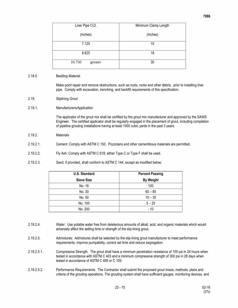
2.18.5. Bedding Material.
Make point repair and remove obstructions, such as roots, rocks and other debris, prior to installing liner pipe. Comply with excavation, trenching, and backfill requirements of this specification.
2.19. Sliplining Grout
2.19.1. Manufacturers/Application
The applicator of the grout mix shall be certified by the grout mix manufacturer and approved by the SAWS Engineer. The certified applicator shall be regularly engaged in the placement of grout, including completion of pipeline grouting installations having at least 1000 cubic yards in the past 3 years.
2.19.2. Materials
2.19.2.1. Cement: Comply with ASTM C 150. Pozzolans and other cementitious materials are permitted.
2.19.2.2. Fly Ash: Comply with ASTM C 618; either Type C or Type F shall be used.
2.19.2.3. Sand, if provided, shall conform to ASTM C 144, except as modified below:
U.S. Standard Percent Passing
Sieve Size By Weight
No. 16 100
No. 30 60 – 85
No. 50 10 – 35
No. 100 5 – 25
No. 200 - 10
2.19.2.4. Water: Use potable water free from deleterious amounts of alkali, acid, and organic materials which would adversely affect the setting time or strength of the slip-lining grout.
2.19.2.5. Admixtures: Admixtures shall be selected by the slip-lining grout manufacturer to meet performance requirements, improve pumpability, control set time and reduce segregation.
2.19.2.5.1. Compressive Strength. The grout shall have a minimum penetration resistance of 100 psi in 24 hours when tested in accordance with ASTM C 403 and a minimum compressive strength of 300 psi in 28 days when tested in accordance of ASTM C 495 or C 109.
2.19.2.5.2. Performance Requirements. The Contractor shall submit the proposed grout mixes, methods, plans and criteria of the grouting operations. The grouting system shall have sufficient gauges, monitoring devices, and
7086
24 - 70 02-16 OTU
test to determine the effectiveness of the grouting operation and to ensure compliance with the liner pipe specifications and design parameters.
2.19.2.5.3. Mix Designs. One or more mixes shall be developed to completely fill the annular space based, but not restricted to, the following requirements:
Size of annular void
Void (size) of the surround soil
Absence or presence of groundwater
Sufficient strength and durability to prevent movement of the line pipe.
Provide adequate retardation, and
Provide less than 1 percent shrinkage by volume.
2.19.2.5.4. Density/Viscosity. The Contractor shall design a grout mix with a density to prevent floating of the liner pipe. The apparent viscosity shall not exceed 20 seconds in accordance with ASTM C 939 unless otherwise approved by the SAWS engineer.
2.20. Bedding and Backfill
Backfilling for sanitary sewers is divided into three (3 separate zones: (a) bedding: the material in trench bottom in direct contact with the bottom of the pipe; (b) initial backfill: the backfill zone extending from the surface of the bedding to a point 1 foot above the top of the pipe; and (c) secondary backfill: the backfill zone extending from the initial backfill surface to the top of the trench. Materials and placement for each of the zones shall be as described herein.
2.20.1. Bedding.
Stable Material: Existing stable material present during excavation including:
Trench bottom free of water, muck, debris;
Rock in boulder, ledge or coarse gravel (particle size not larger than 1- ¾ inch) formations;
Coarse sand and gravels with maximum particle size of 1- ¾ inch, various graded sands and gravels containing small percentages of fines, generally granular and non-cohesive either wet or dry; and
Fine sands and clayey gravels; fine sand, sand-clay mixtures, clay and gravel-clay mixtures.
Unstable Material: Existing unstable materials are: Silt, muck, trash or debris in the trench bottom bearing level; rock, in ledge or boulder, or coarse gravel (minimum particle size larger than 1- ¾ inch) formations.
Bedding Material: The existing material at the bearing level shall be removed and replaced to a minimum depth of 6 inches or 1/8 of the outside diameter of the pipe, whichever is greater, with bedding material. The bedding material shall extend up the sides of the pipe sufficient to embed the lower quadrant of the pipe. The bedding material shall be composed of well-graded, crushed stone or gravel conforming to the following requirements unless modified by the Engineer in writing.
Sewer Gravel Percent Passing 1-1/2 inch sieve 100 Passing 1 inch sieve 95 – 100 Passing 1/2 inch sieve 25 – 60 Passing No. 4 sieve 0 – 10 Passing No. 8 sieve 0 – 5

7086
25 - 70 02-16 OTU
Over Excavation: Where the trench bottom has been over excavated beyond the limits as defined in Item No. 848, “Sanitary Sewers,” due to removal of unstable material, the pipe shall be concrete-encased. Encasement shall extend from the trench wall to trench wall and be a minimum of 6 inches above the top of pipe. No separate pay item..
Reduced Excavation: Where the trench bottom is not excavated in accordance with the specification due to rock or other hard under lying materials, then the pipe shall be concrete encased. No separate pay item.
Consolidating Backfill Material: The Initial Bedding material shall be consolidated to assure it is incorporated from the bottom of the trench up to the pipe centerline. A hand-held vibrator, commonly used for concrete work, can be used for this purpose. The vibrator shall be inserted every 3 feet on each side of the pipe.
2.20.2. Initial Backfill
Initial backfill is defined as backfill having a thickness in its compacted state from the surface of the bedding to a point 1 foot above the top of the pipe.
Initial backfill shall consist of gravel which conforms to the requirements for bedding material.
2.20.3. Secondary Backfill
Secondary backfill is defined as backfill from 1 foot above the top of the pipe to the top of the trench or bottom of pavement section. Secondary backfill shall be constructed in accordance with details shown in the construction documents.
Secondary backfill shall generally consist of materials removed from the trench and shall be free of brush, debris and trash. Rock or stones having a dimension larger than 6 inches at the largest dimension shall be sifted out and removed before the material is used in the secondary backfilling zone. Secondary backfill material shall be primarily composed of compactible soil materials.
The secondary backfill material shall be placed in maximum 12 inch loose lifts or as directed by the Design Engineer and/or Inspector.
3. CONSTRUCTION
3.1. Excavation
Excavation as required to complete the work as outlined herein will be performed in accordance with Item 400, “Excavation and Backfill for Structures”.
3.1.1. Trench Excavation Protection
Excavation greater than 5-ft. in depth is to be protected as specified in Item 402, “Trench Excavation Protection”, or Item 403, “Temporary Special Shoring”.
3.1.2. Trenches
Trench walls shall be vertical. The practice of undercutting at the bottom or flaring at the top will not be permitted except where it is justified for safety or at the Engineer’s and/or Inspector’s direction. In special cases, where trench flaring is required, the trench walls shall remain vertical to a depth of at least 1 foot above the top of the pipe.
The trench bottom shall be square or slightly curved to the shape of the trenching machine cutters. The trench shall be accurately graded along its entire length to provide uniform bearing and support for each section of pipe installed upon the bedding material. Bell holes and depressions for joints shall be dug after

7086
26 - 70 02-16 OTU
the trench bottom has been graded and bedding installed. The pipe shall rest upon the new bedding material for its full length.
Where over-excavation occurs and when not as directed by the Engineer or Inspector, the under-cut trench shall be restored to grade at no cost to SAWS by replacement with a material conforming to the requirements of the bedding material or a material approved by the Engineer.
3.2. Width of Trench
Minimum Width of Trench. The minimum width of pipe trenches, measured at the crown of the pipe, shall be not less than 12 inches greater than the exterior diameter of the pipe, exclusive of bells. The minimum base width of such trench shall be not less than 12 inches greater than the exterior diameter of the pipe, exclusive of special structures or connections. Such minimum width shall be exclusive of trench supports and not greater than the width at the top of the trench.
Maximum Width of Trench. The maximum allowable width of trench for pipelines measured at the top of the pipe shall be the outside diameter of the pipe (exclusive of bells or collars) plus 24 inches. A trench wider than the outside diameter plus 24 inches may be used without special bedding if the Contractor, at his sole expense, furnishes pipe of the required strength to carry additional trench load. Such modifications shall be submitted to the Inspector and approved in writing. Whenever such maximum allowable width of trench is exceeded, except as provided for in the contract documents, or by written approval of the Engineer, the Contractor, at his sole expense, shall encase the pipe in concrete from trench wall to trench wall, or with other approved pipe bedding material. Any excavation wider than this maximum width or subsequent surface or paving work, will be done at the Contractor’s sole expense.
3.2.1. Classification of Excavated Materials
No classification of excavated materials will be made. Excavation and trench work is to include the removal and subsequent handling of all materials excavated in accordance with Item 400, “Excavation and Backfill for Structures”.
3.2.2. Grade of Trench Bottom
The trench is to be over-excavated to a depth of 6-in. below the grade line established for the bottom of the pipe, regardless of the type of pipe. The grade line of the pipe is to then be met by the addition of a layer of approved bedding material as directed.
3.2.3. Excavation Below Grade
Any part of the bottom of the trench excavated below the limits specified in Section 3.1.4., “Grade of Trench Bottom”, is to be corrected with approved material and compacted as directed. Should excessive over-excavation occur, except at bell holes, the grade is to be restored in accordance with the methods described in Section 3.1.6, “Unstable Conditions at Grade”, at no cost to the Department.
3.2.4. Unstable Conditions at Grade
Where the bottom of the trench at grade is found to be unstable or to include ashes, cinders, any type of refuse, vegetable or other organic material, or large pieces of fragments or inorganic materials which in the judgment of the Engineer should be removed, the Contractor is to excavate and remove such unsuitable material to the a depth no less than 6-inches below pipe. Before the pipe is laid the grade is to be restored by backfilling with an approved material in layers of 3-in. prior to compaction. The layers are to be slightly moistened and thoroughly compacted so as to provide a uniform and continuous bearing and support for the pipe at every point between bell or collar holes. The finished grade is to be accurately graded to provide uniform bearing and support for each section of pipe at every point along its entire length except for the portions of the pipe sections where it is necessary to excavate for bell holes and for the proper seating of pipe joints.

7086
27 - 70 02-16 OTU
3.2.5. Caution in Excavation
The Contractor is to proceed with caution in the excavation and preparation of the trench so that the exact location of underground structures and utilities may be determined whether shown on the plans or not. Machine excavation is not permitted closer than 12-in. on either side of other existing underground utilities. The Contractor is to be responsible for the repair of such structures and utilities when broken or damaged. He is also to be responsible for adjusting alignment and trench grades with reference to such structures in order to obtain specified clearance for the sewer main construction.
Whenever the Engineer determines that it is necessary to explore and excavate to determine the location of existing underground structures and utilities, the Contractor is to make explorations and excavations for such purposes at his expense. Backfill Material Derived from Excavation.
Any excess excavated material, not utilized after all fill requirements have been met, shall become the responsibility of the Contractor. The Contractor shall dispose of it by hauling and wasting outside the limits of the rights-of-way or easements of this project and of public thoroughfares and water courses, in conformity with pertinent City, County, State and Federal codes and ordinances and in a manner meeting the approval of the Engineer.
3.2.6. Trench Restoration
The surface of the backfilled trench shall be restored to match the previous existing conditions. This shall include final grading, placement of topsoil and seeding, placement of sod (such as at homes or businesses that had maintained grass), or other unprepared and prepared surfaces.
Trenches in alleys actively being used by vehicles (such as trash pickup, vehicle parking, etc.) shall be restored by grading and compacting to 98% or higher with a minimum of 4 inches of flexbase materials for the entire width of the alley. Asphaltic materials shall have a compaction density of 95%. Alleys not actively used by vehicles shall be graded and compacted to 98% or higher from the top of the initial backfill to the bottom of the pavement section, then spread grass seed for entire width of the alley.
Trenches in paved streets shall be covered with a temporary all weather surface to allow for vehicular traffic until the final asphalt/concrete paving is complete. This surface shall be a minimum of 4 inches compacted and rolled asphaltic black base, either hot-mix or cold-mix applied. It is the Contractor’s responsibility to maintain this surface until the final street restoration is complete. Temporary street striping may also be required. This surface must be removed prior to final asphalting.
All street work shall be done in accordance with the latest TXDOT construction specifications. Included in this requirement is replacement of any curbs or sidewalks damaged or removed during the construction.
No separate payment for the surface restoration is permitted. The cost for this work must be included in the appropriate bid item.
3.2.7. Pavement.
The Contractor is to remove pavement and surfaces as a part of the trench excavation. The removal of pavement and surfaces and their restoration is to be based on the minimum trench widths as specified, plus 6-in. either side or as otherwise provided herein. The Contractor is to use such methods as sawing, drilling, or chipping to assure the breaking of the pavement along straight lines.
If the Contractor removes or damages pavement or surfaces beyond the limits specified above, such pavement and surfaces are to be restored at the expense of the Contractor.
Where water line construction necessitates cutting through existing streets outside the limits of new street construction, said streets are to be replaced in kind as directed. Where, in the opinion of the Engineer, it is

7086
28 - 70 02-16 OTU
necessary to maintain traffic across a trench, the Contractor is to install temporary metal bridges as necessary to facilitate the movement of traffic.
The street surface adjacent to the trench is to be kept free of surplus spoil. Construction materials are to be placed at locations that will minimize interference with the traveling public.
3.2.8. Concrete Sidewalks, Driveways, Etc.
All concrete sidewalks, driveways, etc., are to be cut with a concrete saw. When transverse expansion or “dummy” joints are encountered, the concrete is to be removed to the nearest transverse joint on each side of the trench and restored. The depth of cut is to be such that upon removal of the concrete, the sides of the cut are to be straight and square.
Existing reinforcing wire fabric or bars are to be cut and removed to permit completion of trench excavation, pipe laying, and backfill operations. When the backfill operations have been completed, the existing reinforcement is to be replaced in its original position and satisfactorily spliced prior to the replacement of concrete over the new trench alignment.
Transverse “dummy” joints are to be made by a jointing tool or other means acceptable, and are to match in depth and thickness in the existing transverse joints.
Expansion joint material is to be provided where new construction abuts the existing curb or driveway if the Engineer deems it necessary.
Concrete is to be spaded, tamped, and thoroughly compacted until mortar entirely covers the surface and has a monolithic finish. The top surface is to be floated, troweled, and finished to match the existing concrete surface.
Immediately after finishing, the concrete surface is to be protected by a membrane compound curing agent, or by wetted cotton or burlap mats. Either method is to be subject to approval.
3.2.9. Dewatering.
Prevent surface water and subsurface or ground water from flowing into excavations and from flooding project site and surrounding areas.
The contractor shall not allow water to accumulate in excavations or at subgrade level. Remove water to prevent softening of foundation bottoms and soil changes detrimental to stability of subgrades and foundations. Provide and maintain dewatering system components necessary to convey water from excavations.
Convey water removed from excavation and rainwater to collecting or runoff areas away from buildings and other structures. Establish and maintain temporary drainage ditches and other diversion outside excavation limits. Do not use trench excavations as temporary drainage ditches.
Dewatering devices shall be provided by the Contractor with filters to prevent the removal of fines from the soil.
Should the pumping system draw fines from the soil, the Engineer shall order immediate shutdown, and remedial measures will be responsibility of the Contractor.
Upon completion of the dewatering work, the Contractor shall remove all equipment and leave the construction area in a neat, clean, condition that is acceptable to the Owner.
The Contractor shall maintain ground water table at least 12 inches below the finished excavation subgrade.

7086
29 - 70 02-16 OTU
Dewatering Performances. Performances of the dewatering system for lowering ground water shall be measured by observation wells on piezometers installed I conjunction with the dewatering system, and these shall be documented at least daily. The Contractor shall maintain a log of these readings and submit them to the Owner.
No direct payment shall be made for costs associated with dewatering. All costs in connection therewith shall be included I the applicable contract price for the item to which the work pertains.
3.2.10. Bedding and Backfill
3.2.10.1. General
Trenches shall not be backfilled until the construction structures or appurtenances, as installed, conform to the requirements specified. Where specified, only the secondary backfilling may incorporate excavated materials approved for backfilling, consisting of earth, loam, sandy clay, sand and gravel, soft shale or other approved materials, free from large clods of earth or stones. Where pipe is specially coated or sleeve/tape wrapped for protection against corrosion, care shall be taken not to damage the coating or sleeve/tape wrap.
Where a trench has been improperly backfilled, or where settlement occurs, the identified section shall be excavated to a depth and length 50 feet beyond the failed area, then refilled and compacted to the grade and compaction level required. The use of sand backfill shall not be allowed. All compaction within the secondary backfill zone shall be such that the apparent dry density of each layer shall be not less than 98% from the top of the initial backfill to the bottom of pavement section. The pavement (asphalt) section shall have 95% compaction density with a maximum dry density at + or – 2% optimum moisture content as determined by tests on samples as outlined in the latest provisions of TX-DoT Testing Method Tex 113-E or most applicable approved equal provisions, unless otherwise shown on the contract documents. At the time of compaction, the water content shall be at optimum moisture content, + or - 2% points.
3.2.10.2. Initial Backfill
Prior to laying the pipe, the normal or select bedding material will be shaped to conform to the outside diameter of the pipe as shown on the plans. Bedding material shall be consolidated to assure it is incorporated from the bottom of the trench up top the pipe centerline. A hand-held vibrator, commonly used for concrete work, can be used for this purpose. The vibrator shall be inserted every 3 feet on each side of the pipe.
For sewer lines up to 24 inches in diameter initial backfill material shall be placed in two lifts above the bedding material the pipe is set on. The first lift shall be spread uniformly and simultaneously on each side and under the bottom quadrant of the pipe to the midpoint or spring line of the pipe. Consolidate the Initial Backfill material as specified for bedding.
Placement of the first lift of initial backfill shall be subject to inspection and approval prior to placement of second lift, which shall extend from the spring line of the pipe to a minimum of 1 foot above the top of the pipe. The second lift shall be evenly spread in a similar manner as the first lift.
For diameters 24 inches and larger, initial backfill material shall be evenly and simultaneously spread alongside, under the lower quadrant the pipe and over the pipe in 12 inch lifts to a point sufficient to a minimum of 1 foot above the top of the pipe. Consolidate the Initial Backfill material as specified for bedding.
3.2.10.3. Secondary Backfill
The secondary backfill material shall be placed in maximum 12 inch loose lifts or as directed by the Design Engineer and/or Inspector.
3.3. Pipe Installation

7086
30 - 70 02-16 OTU
3.3.1. General
All sanitary sewer mains shall be constructed in accordance with the specifications herein outlined and in conformity with the required lines, grades, and details shown on the plans and as directed by the Engineer. Successful passage of the air and mandrel test (for flexible pipe, 30 days after installation), as described under TCEQ 30 TAC 217.53 Criteria, shall be required for the acceptance of the mains.
After the trench has been carefully graded and all bell holes excavated, approval is required prior to placing the pipe therein.
All sewers are to be laid in straight alignment, so that a light can be seen from one manhole to the other even for the smaller size of sewers. The pipe is to be laid accurately to line and grade, with the spigot end downstream entering the bell to full depth and in such a manner as not to drag earth into the annular space. Pipes and fittings are to be fitted together and matched so that they will form a sewer with a smooth and uniform invert. Special care is to be taken to provide uniform bearing for the entire length of pipe.
Water Main Crossings: Where gravity or force main sewers are constructed in the vicinity of water mains, the requirements of the TCEQ 30 TAC 217.53 (d), shall be met.
Pipe and Fittings. Proper and suitable tools and appliances for the safe and convenient handling of the pipe and fittings are to be provided and used. Care is to be taken to prevent any damage to the pipe coating. All pipe and fittings will be examined for defects right before placing into the trench and no materials are to be laid that are known to be defective.
Any defective pipe discovered after being laid is to be removed and replaced with acceptable pipe at the Contractor’s expense. Wherever the pipe requires cutting, it is to be done with a standard wheel pipe cutter for pipe 12-in. and smaller. Cutting methods for larger pipes are to be as approved. Each cut is to be smooth and at right angles to the axis of the pipe.
Pipe Laying: The Contractor shall be required to commence construction and laying of pipe at the downstream end of the sanitary sewer outfall line and proceed non-stop in a forward upstream direction.
No pipe shall be laid within 10 feet of any point where excavation is in progress. Pipe laying shall proceed upgrade with the tongue or spigot pointing in the direction of flow. Pipe shall be lowered into the trench without disturbing the prepared foundation or the trench sides.
The drilling of lifting holes in the field will not be permitted. Pipe shall be installed by means of a concentric pressure being applied to the pipe with a mechanical pipe puller. Pulling or pushing a joint of pipe in place by using a crane, bulldozer, or backhoe will not be permitted. Pipe shall be pulled home in a straight line with all parts of the pipe on line and grade at all times. No side movement or up and down movement of the pipe will be permitted during or after the pulling operation.
Should coupled joints of pipe be out of line or off grade, they shall be removed one joint at a time and brought to the proper line and grade. The lifting or moving of several joints of coupled pipe at one time to close a partially open joint or to fine grade under laid joints of pipe will not be permitted.
Laser Beams: The use of laser Beams for vertical control shall be required provided the Contractor makes available to the Inspector, when requested, a level and rod of sufficient sensitivity to accurately determine differences in elevation between points 300 feet apart with one instrument set-up. Contractor shall provide a written summary to the Inspector of all elevations that all installed, repaired, or replaced sewer main enter and exit a manhole or structure.
No pipe shall be installed in tunnels except as provided on the plans, or with the permission of the Engineer. If the Contractor finds it necessary to install pipe in tunnels not provided on the plans, he shall submit to the Engineer, prior to commencement of work, a detailed outline of procedures, methods, and use of materials depending on existing soil conditions.

7086
31 - 70 02-16 OTU
No horizontal or vertical curves shall be permitted in conformance with appropriate regulatory agency requirements.
Before leaving the work unattended, the upper ends of all pipelines shall be securely closed with a tight fitting plug or closure. The interior of laid pipe shall be kept free from dirt, silt, gravel, or foreign material at all times. All pipes in place must be approved before backfilling.
When replacing an existing system in place, Contractor shall maintain screens to prevent the entrance of construction debris into the sewer system.
Pipe Separation: Sewer pipe separation distances shall be maintained in accordance with TCEQ rules 30 §217.53.
3.3.2. Service Connections (Sanitary Sewer Laterals)
Sanitary sewer laterals fittings and appurtenances shall conform to the Sanitary Sewer specifications and shall be installed by the Contractor as specified herein, or as directed by the Construction Inspector or the Engineer and in accordance with the plans. Where the lateral is within the Edwards Underground Recharge Zone then it shall be installed in accordance with details.
Service line Installation: All service line installations shall be performed in accordance with this specification. For sanitary sewer mains that are 12” in diameter or smaller, all laterals shall be connected using the appropriate size tee/wye placed in line with the main line. For mains larger than 12", insert-a-tee conforming to ASTM 3034-88 or approved or equal may be used. Where waterline crossings with sanitary sewer laterals are less than the regulated separation distances, all lateral piping shall be SDR-26 PVC pipe (ASTM D2241-09) with a pressure rating of 150 psi.
Connection to the customer’s end of the lateral shall be performed using a flexible coupling, or pre-approved equal. All flexible couplings shall be concrete-encased to prevent movement or breakage of the steel bands. All cleanouts at job sites shall have installed an approved heavy duty sanitary sewer cap.
Cutting, excavation, and backfill shall be as specified herein.
Service Connections:
Provide reconnections of all existing sewer service laterals to new lines installed or to provide
connections of new laterals to existing sanitary sewer mains. Locate laterals and insure service is not
interrupted to homes or other establishments.
Wyes, bends, tees, stacks, and other hardware required are to be installed for service laterals as
shown on the plans or as directed.
3.3.3. HDPE Pipe Joining
Bending of HDPE pipe will be done in accordance with the manufacturer’s instructions.
3.3.4. Pipe Joint Restraint System for HDPE Pipe
Restraint devices will be used where ductile iron mechanical joint bell fittings are coupled to plain-end (square-cut) HDPE pipe, to prevent movement of pipe connections. Mechanical joint adapters will be required for the HDPE pipe.
All restraint devices will be installed in accordance with the manufacturer’s instructions.
3.3.5. Coating and Wrapping Underground Steel Pipe
7086
32 - 70 02-16 OTU
Exterior surfaces of all steel pipe fittings and specials which are to be installed underground and which are not to be encased in concrete will be cleaned to bare metal by wire brushing with a power driven wire brush, sand blasting, or other approved methods. A prime coat compatible to the polyvinyl tape to be used will then be applied to the pipe. Following the application of the prime coat, the pipe will be wrapped with Scotchrap, Trantex V-10 polyvinyl tape, or approved equal. The tape will not be applied until the prime coat in completely dry.
The tape will be spirally and tightly wrapped on each section of the pipe with a 50 percent lap. The joint will be protected with tape 8-in. in width on pipe greater than 12-in. in size.
Each section of pipe will be cleaned, primed, and wrapped to within 6-in. of each end. The priming and wrapping will be completed, and the bare pipe wrapped with tape lapped 3-in. over the originally taped sections.
3.3.6. Protective Coating and Wrapping on Joints
All bolts and nuts installed for underground service on cast-iron mechanical joint fittings and other ferrous metal appurtenances will be packed in an approved protective coating material after installation. After the joint has been made and bolts drawn to proper tension, the joint including glands, flanges, bolt heads, and nuts shall be covered with an approved SAWS coating. Coating and wrapping of joints will be considered subsidiary to the installation and will not be paid for directly. Asphaltic material such as Talcote shall not be used.
3.4. Manhole Construction
Manhole construction is to be in accordance with Item 465, “Manholes and Inlets”, and as specified herein.
Footings or bases of manholes shall be a minimum of 6 inches in depth below the bottom of the pipe.
All invert channels of manholes are to be constructed and shaped accurately so as to be smooth, uniform and cause minimum resistance to flow. The bench is to be finished smooth with a slope of 1/2-in./ft. from the manhole walls to the edges of the invert. The top half of all sewer pipes within the invert channel or bench zone are to be removed flush to the inside manhole walls.
Joints on sewer pipes are not to be cast or constructed within the wall sections of manholes.
Concrete cradles are not required for new pre-cast manholes. Concrete cradles are to be provided for all influent and effluent pipes on new monolithic manhole and sewer pipe systems. Concrete cradles are to extend beyond the outside walls of the manhole a minimum of 36-in.
Voids between exterior pipe walls and manhole walls at all pipe connections in manholes shall be filled with a non-shrink grout, concrete or mortar, as approved by the Engineer or as shown in the contract documents and inspected prior to backfilling.
Where connections to existing manholes are required, the adjacent pipe bedding is to be prepared to proper grade, the existing manhole neatly cut and the new pipe inserted so that the end is projecting 2-in. from the inside wall. The invert is then to be reshaped to properly channel new flows. Debris of any kind is to be kept out of new or existing manholes or mains.
Throat rings shall be mortared between all bearing surfaces sufficient to provide a minimum, in place, mortar thickness of ¼ inch. No more than 4 throat rings may be used on any manhole or no more than 21 inches from the top of the cone to the top of the ring and cover.
Manhole Ring Encasement. All manhole rings are to be encased with 4000 psi reinforced Class B concrete as shown on the plans or approved by the Engineer. Manhole ring encasements are to extend 6-in below the
7086
33 - 70 02-16 OTU
top of the cone and have a minimum thickness when measured at the manhole ring of 1-ft. The surface of the encasement is to be 4-1/2-in. below the top of the manhole ring as shown on the plans or as approved.
Where manholes are constructed in existing or proposed roadways and where directed or shown on the plans, the exterior exposed surfaces of the ring, mortar, throat rings, and manhole surface are to be coated with a 1/8-in. minimum thickness of mastic or plastic prior to placement of concrete.
3.5. Manhole Rehabilitation
Described are procedures for cleaning, preparation, application, and testing. The applicator, approved and trained by the manufacturer, shall furnish all labor, equipment and materials for applying a cementitious mix to form a monolithic liner of a minimum 1/2-in. thickness, with machinery specially designed for the application. All aspects of the installation shall be in accordance with the manufacturer’s recommendation and as per this specification, which includes:
the removal of any loose and unsound material,
cleaning of the area to be restored with high pressure water,
repair and filling of voids,
repair and sealing of invert and benches,
elimination of active infiltration prior to making the application, and
spray application of a cementitious mix to form a structural or structurally enhanced monolithic liner.
Certification: Manufacturer shall certify that applicator has been trained and approved in the handling, mixing and application of the products to be used. Equipment to be used for applying the products by the Applicator shall be certified and approved by the Manufacturer. Five recent references of Applicator indicating successful application of proposed liner on projects of similar size and scope shall be submitted by Contractor.
Surface Preparation: Proper surface preparation procedures must be followed to ensure adequate bond strength to any surface to be coated. Applicator shall inspect all surfaces specified to receive a liner prior to surface preparation. Applicator shall notify Owner of any noticeable disparity in the surfaces which may interfere with the proper preparation or application of the repair mortar or liners. Concrete that is not sound or has been damaged by chemical exposure shall be removed to a sound, concrete surface. All containments, including: All oils, grease, incompatible existing coatings, waxes, form release, curing compounds, efflorescence, sealers, salts, or other contaminants shall be removed. Surface preparation methods should be based upon the condition of the substrate and the requirements of the liner to be applied.
Surface to receive liner shall be cleaned and abraded to produce a sound concrete surface with adequate profile and porosity to provide a strong bond between the protective coating and substrate. High pressure cleaning with a minimum of 4,000 psi and 4 gallon per minute using a rotating pencil nozzle, shall be used to clean and free all foreign material within the manhole. Detergent water and cleaning or muriatic acid shall be used when grease and oil are present. All materials resulting from the cleaning of manhole shall be removed prior to application of coating.
Active water infiltration shall be stopped by using a cementitious water plug or hydro-active grout such as Strong-Seal Strong Plug, Quadex Hydra-Plug or approved equal which is compatible with the specified coating. Prepared surfaces should be tested, after cleaning but prior to application of the coating, if a specific pH or moisture content of the concrete is required according to manufacturer’s recommendations.
Product Handling and Rehabilitation Conditions: Protective coating materials are to be handled according to their material safety data sheets. Materials are to be kept dry, protected from weather and stored under cover.
Repair and under-coat materials must be accepted and approved by the protective coating manufacturer for compatibility with the specified liner and shall be used to fill voids, structurally reinforce and rebuild surfaces, etc., as determined necessary. The Engineer shall determine type of manhole rehabilitation to be used according to the following:

7086
34 - 70 02-16 OTU
Condition. The manhole is assured to be exhibiting severe structural fatigue and collapse is imminent. Conditions indicating this degree of deterioration would be distortion beyond 10 percent, severe corrosion (exposed reinforcing), or large section (greater than 30 percent) of the structure is missing. An approved structural liner followed by a compatible approved non-structural (sulfate resistant) protective liner shall be used to rehabilitate the manhole. A letter from the manufacturer will be submitted certifying the compatibility of the structural liner with the corrosion resistant protective coating.
Liner Application: Application procedure shall conform to the recommendations of the liner manufacturer, including materials handling, mixing, environmental controls during application, safety and equipment. The liner application equipment shall be specifically designed to accurately apply the specified liner material and shall be regularly maintained and in proper working order. The liner material must be applied by a Certified Applicator of the liner manufacturer. The liner shall be applied to minimum thickness or as specified according to the Owner’s requirements and Manufacturer’s recommendations. Temperature of the surface to be coated shall be maintained between 40° F and 120° F during application. Prior to and during application, care should be taken to avoid exposure of direct sunlight or other intense heat source to the structure being coated. Where varying surface temperatures exist, care should be taken to apply the liner when the temperature is falling versus rising (late afternoon into evening versus early morning into afternoon).
Warranty: Contractor shall warrant to the Owner all work against defect in materials and workmanship for a period of 2 years, unless otherwise noted, from the date of final acceptance of the project. Applicator shall, within a reasonable time after receipt of written notice thereof, repair defects in material or workmanship which may develop during said 2 year period and any damage to other work caused by such defects for the repairing of same, at their own expense and without cost to the Owner.
3.6. Cleaning Manholes and Mains
The sanitary sewer lines and structures that are to be rehabilitated shall be cleaned using mechanical, hydraulically propelled or high velocity sewer cleaning equipment. The cleaning process shall remove all grease, sand, silts, solids, debris, etc. from each sewer segment, including the manholes. Selection of cleaning equipment and method for cleaning shall be based on the condition of the sanitary sewer mains at the time work commences and will be subject to approval. All cleaning equipment and devices shall be operated by experienced personnel. Satisfactory precautions shall be taken to protect the sanitary sewer mains and manholes from damage that might be inflicted through the improper use of the cleaning process or equipment. Any damage done to a sewer by the Contractor shall be repaired by the Contractor at the Contractor’s expense to satisfaction. Cleaning shall also include washing of the manhole wall by high pressure water jet.
During Construction the Contractor Shall: Keep the work and surrounding premises within work limits free of accumulations of dirt, dust, waste materials, debris and rubbish.
Keep dust generating areas wetted down.
Provide suitable containers for storage of waste materials, debris and rubbish until time of disposal.
Dispose of waste, debris and rubbish off site at legal disposal areas.
Remove and dispose of all excess or waste materials, debris and rubbish from the site, structures and all facilities at the end of working hours.
The Contractor, when instructed, will be required to demonstrate the performance capabilities of the cleaning equipment proposed for use. If the results obtained by the proposed sanitary sewer cleaning equipment are not satisfactory, the Contractor shall use different equipment or attachments, as required, to meet specification. More than one type of equipment or attachments may be required at a location. When hydraulic or high velocity cleaning equipment is used, a suitable sand trap, weir, dam or suction shall be constructed in the downstream manhole in such a manner that all solids and debris are trapped for removal.
7086
35 - 70 02-16 OTU
Whenever hydraulically-propelled cleaning tools which depend upon water pressure to provide their cleaning force, or any tool which retard the flow of water in the sanitary sewer lines are used, precautions shall be taken to insure that the water pressure created does not cause any damage or flooding to public or private property being served by the manhole section involved. Any damage of property, as a result of flooding, shall be the liability and responsibility of the Contractor. The flow of wastewater present in the sanitary sewer main shall be utilized to provide necessary fluid for hydraulic cleaning devices whenever possible. When additional quantities of water from fire hydrants are necessary to avoid delay in normal working procedures, the water shall be conserved and not used unnecessarily. No fire hydrant shall be obstructed or used when there is a fire in the area. The Contractor shall be responsible for obtaining the water meter and all related charges for the set-up, including the water usage bills from respective water purveyor agency. All expenses shall be considered incidental to the cleaning of the existing sanitary sewer mains.
Hydraulic Cleaning: Hydraulic propelled devices which require a head of water to operate must utilize a collapsible dam. The dam must be easily collapsible to prevent damage to the sewer, surrounding property, etc. When using hydraulically propelled devices, precautions shall be taken to insure that the water pressure created does not cause damage or flooding to public or private property. The Contractor shall not increase the hydraulic gradient of the sanitary sewers beyond the elevation that could cause overflow of sewage into area waterways or laterals. The flow of wastewater present in the sanitary sewer main shall be utilized to provide necessary fluid for hydraulic cleaning devices whenever possible.
High Velocity Cleaning: Cleaning equipment that uses a high velocity water jet for moving debris shall be capable of producing a minimum volume of 50 GPM with a pressure of 1,500 psi for the sanitary sewer line and 3,500 psi for the (manhole) structure at the pump. Any variations to this pumping rate must be approved, in advance. To prevent damage to older sewer mains and property, a pressure less than 1500 psi can be used. A working pressure gauge shall be used on the discharge of all high pressure water pumps. The Contractors shall use, in addition to conventional nozzles, a nozzle which directs the cleaning force to the bottom of the pipe for sewers 18-in. and larger. The Contractor shall operate the equipment so that the pressurized nozzle continues to move at all times. The pressurized nozzle shall be turned off or reduce anytime the hose is held or delayed in order to prevent damage to the line.
Mechanical Cleaning: Mechanical cleaning, in addition to normal cleaning when required, shall be with approved equipment and accessories driven by power winching devices. The Contractor shall submit the equipment manufacturer’s operational manual and guidelines, which shall be followed strictly, unless modified. All equipment and devices shall be operated by experienced operators so that they do not damage the pipe in the process of cleaning. Buckets, scrappers, scooters, porcupines, kites, heavy duty brushes, metal pigs and other debris removing equipment and accessories shall be used as appropriate and necessary in the field, in conjunction with the approved power machines. The use of cleaning devices such as rods, metal pigs, kites, porcupines, root saws, snakes, scooters, sewer balls and other approved equipment, in conjunction with hand winching device, or gas, electric rod propelled devices, shall be considered normal cleaning equipment.
3.7. Jacking, Boring, or Tunneling Pipe
Jacking: Suitable pits or trenches shall be excavated for the purpose of jacking operations for placing end joints of the pipe. When trenches are cut in the side of embankment, such work shall be securely sheeted and braced. Jacking operations shall in no way interfere with the operation of railroads, streets, highways or other facilities and shall not weaken or damage such facilities. Barricades and lights shall be furnished as directed by the Engineer to safeguard traffic and pedestrians.
The pipe to be jacked shall be set on guides to support the section of pipe being jacked and to direct it in the proper line and grade. Embankment material shall be excavated just ahead of the pipe and material removed through the pipe, and the pipe forced through the opening thus provided.
The excavation for the underside of the pipe, for at least ⅓ of the circumference of the pipe, shall conform to the contour and grade of the pipe. A clearance of not more than 2 inches may be provided for the upper half of the pipe.

7086
36 - 70 02-16 OTU
The distance that the excavation shall extend beyond the end of the pipe shall depend on the character of the material, but it shall not exceed 2 feet in any case.
The pipe shall be jacked from downstream end. Permissible lateral or vertical variation in the final position of the pipe from line and grade will be as shown on the plans or as determined by the Engineer.
Any pipe that cannot be repaired to its original condition or is damaged in jacking operations shall be removed and replaced at the Contractor's expense. Jacking pits shall be backfilled immediately upon completion of jacking operations.
Excavation for "Boring" pits and installation of shoring shall be as outlined under "Jacking." Boring operations may include a pilot hole which shall be bored the entire length of crossing and shall be used as a guide for the larger hole to be bored. Water or drilling fluid may be used to lubricate cuttings. Variation in line and grade shall apply as specified under "Jacking."
Tunneling: Tunneling may be used when the size of the proposed pipe would make the use of tunneling more satisfactory than "Jacking" or "Boring." The excavation for pits and the installation of shoring shall be as specified under "Jacking." The lining of the tunnel shall be of the material shown on the plans.
Access holes for grouting annular space shall be spaced a maximum of 10 feet.
Joints: Joints for pipe for "Jacking," "Boring," or "Tunneling,” shall be as specified in these specifications, or as shown on the project plans or shop drawings as per pipe manufacturer's recommendation.
Grouting of Bores or Tunnels: Annular Space between casing pipe and limits of excavation (borehole) shall be pressure grouted, unless otherwise specified on the plans.
3.8. Concrete Encasement, Cradles, Saddles and Collars
Concrete Encasement. When concrete encasement is shown on the plans or when directed, the trench is to be excavated and fine graded to a depth conforming to the details and sections shown on the plans. The pipe is to be supported by pre-cast concrete blocks of the same strength as the concrete for encasement and securely tied down to prevent floatation. Encasement concrete is to be placed to a depth and width conforming to details and sections shown on the plans.
Concrete Cradles. When concrete cradles are shown on the plans or when directed, the trench is to be prepared and the pipe supported in the same manner as described in Concrete Cradles, of this Section. The cradle shall be constructed in accordance with details and sections shown on the plans. Strap/Tie Downs shall be No. 4 rebar diameter minimum or better as determined by the Water System Inspector.
Concrete Saddles. When shown on the plans or when directed, pipe to receive concrete saddle is to be backfilled in accordance with Section 3.D. of this specification to the spring line and concrete placed for a depth and width conforming to details and sections shown on the plans.
Concrete Collars. When shown on the plans or when directed, concrete collars are to be constructed in accordance with details and sections shown on the plans.
3.9. Adjust or Abandon Manholes
Existing manholes are to be adjusted or abandoned in accordance with Item 479, “Adjusting Manholes and Inlets”, and as specified herein.
Manholes shall be lowered below street subgrade before placing base materials, and openings shall be protected by temporary hatch covers. Manholes adjusted in non-paved areas shall be set per proposed final grade.

7086
37 - 70 02-16 OTU
Existing manhole rings and covers which are determined by the Inspector to be in an unacceptable condition, will be removed and replaced with new rings and covers. If the cone section is removed, the Contractor is to upgrade it to a 30 inch opening as required by 30 TAC § 217. All manhole openings upgraded to 30 inches shall then be considered Reconstruction of Manholes and subjected to all provisions contained under the appropriate section in this specification. Contractor shall take all necessary measures to prevent damage to existing or new rings, covers, or cones from equipment and materials used in, or taken through, the work area. If an existing or new manhole cover, ring, or cone is damaged by the Contractor, it shall be replaced (as directed by the Inspector) by the Contractor at his own expense. If concrete throat rings are to be installed, they must be used in conjunction with a UV stabilized polyethylene liner and I/I barrier. I/I barrier must meet the following ASTM standards: ASTM D790/1505 Density of Polyethylene Materials, ASTM D1238-10 Melt Flow Index, ASTM 638-10 Tensile Strength @ Yield (50mm/mm), ASTM 790 Flexural Modulus, ASTM 648 Heat Deflection Temperature @ IGEPAL, ASTM 1693-12 EsCR, 100% IGEPAL/10% IGEPAL.
Manholes shall be adjusted after the street’s base material has been laid and before placing of the final surface course. Manholes that are going to be adjusted on an existing surface course (not planned for replacement) will be in accordance to the City of San Antonio Utility Excavation Criteria Manual Standard Drawing No. 8.8, but must first be directed by the Engineer. All manholes shall then be raised, or lowered a sufficient height so as to be level with the finished surface course. Adjustment in height will be made by the addition or removal of “throat rings” above the manhole cone, where feasible. A minimum of two and a maximum of six throat rings may be used at each adjusted manhole. All excess materials shall be disposed of by the Contractor at his own expense an in an approved location.
The standard manhole ring and cover shall be ductile iron and manufactured to the dimensions shown in the plans. The ring and cover shall be hinged. Lifting slots cast into the covers shall be provided for lifting purposes. A water-resistant (cam lock) hinged cover shall be used in areas of minimal infiltration potential to allow venting. A watertight (bolt down) ring and covers must be used in areas of high infiltration potential, such as in the Edward’s Aquifer Recharge Zone, an identified 100-year floodplain, or as otherwise directed by the Engineer. The nominal cover diameter shall be 32 inches, with a 30 inch clear opening, as required by TCEQ. Rings shall have a minimum of four 1 inch holes/slots for anchoring purposes. Rings shall be a minimum of 4-1/2 inches in height or as otherwise accepted by the Engineer. Slots for embedment/lightening are not allowed in ring flanges.
Water-Resistant Rings and Covers: Rings and covers shall have two hinges for added stability. The hinge shall have a drain to allow for proper debris and foreign object removal. Prior to acceptance of the work, a stainless steel keyed “cam” lock shall be provided by the Contractor to the Inspector. When the key is inserted in the cam, it shall remain in the lid while the cam is in the open (unlocked) position. When in the closed (locked) position, the key can be removed. When not in use, the cam lock key hole shall be covered with a plastic plug to prevent infiltration of debris. The cover shall positively lock at 90° to prevent accidental closure and open fully to 120°. The cover shall also include a single multi-tool lifting slot adjacent to the edge of the cover to facilitate opening/lifting/prying once it is unlocked. Covers shall be provided with a continuous vulcanized (one piece) EPDM gasket with a shore durometer of 70 ±5 permanently attached to the cover.
Watertight Rings and Covers: Rings and covers shall be the same as above for water-resistant version, except the covers shall be bolted to the ring instead of secured with the cam lock mechanism. No vent hole(s) shall be provided. A minimum of four 1/2 inch diameter, stainless steel, hex head bolts shall be provided for each cover. The 4 bolt holes in the covers shall be evenly spaced and provided with a minimum 1-½ inch diameter counter sink for the bolt heads. On the fastened and bolted position, the bolt heads shall not extend above the surface or the cover. Washers of a size and material as approved by the Engineer shall be provided for the bolts to insure air and water tightness.
The finished ring and cover shall have the bearing surfaces machined ground and sets of rings and covers shall be marked in such a way that they can be matched for assembly in the field. All covers shall have the words "SAN ANTONIO WATER SYSTEM Sanitary Sewer" cast thereon. Ring and cover shall have the approved foundry’s name, part number, country of origin preceded by “Made in” (example: MADE IN USA) in compliance with the country of origin law of 1984, and production date (example: mm/dd/yy) for tracking
7086
38 - 70 02-16 OTU
purposes. Each casting must be marked with DI and ASTM A536 or A536 80-55-06 to verify the materials used. Castings without proper markings shall be rejected.
Material excavation from around the manholes shall be replaced with flowable fill in accordance with these specifications, and select materials from the excavation (as shown in the contract documents). All excess materials shall be disposed of by the Contractor at his own expense and in an approved location. The Contractor also has the option of backfilling with approved secondary materials, subject to the provisions in this specification.
Manholes existing on sewer lines replaced by new sewer piping and which are no longer needed for the revised sewer network are to be classified as “Abandon Manhole”. Work required on an abandoned manhole is to consist of installing a permanent concrete plug on all pipes within the manhole, removing the top of the manhole to an elevation of 2-ft. below proposed subgrade or existing grade, whichever is the lower elevation, and backfilling the manhole with a grout material as specified. The ring and cover of the manholes are to be removed and delievered to Sanitry Sewer Owners facility designated by the Engineer. If directed, drainage holes are to be drilled in the bottom of manhole walls prior to backfilling.
3.10. Cut and Restore Pavement
Where sewers must be installed in streets or other paved areas that are going to remain, the work is required to be in accordance with Item 400, “Excavation and Backfill for Structures”.
When allowed by the construction sequence shown on the plans or as directed, a “Temporary Concrete Cap” of the depth and class of concrete as shown on the plans or as directed may be used in lieu of a permanent repair.
3.11. Concrete Sidewalks, Driveways, Curbs, Medians and Islands Replacement
Existing concrete sidewalks, driveways, curbs, medians and islands required to be removed and replaced solely for sewer installation are to be a part of sewer work. Removal is to be in accordance with Item 104, “Removing Concrete”. Replacement is to be in accordance with the plans and with Item 529, “Concrete Curb, Gutter and Combined Curb and Gutter”, Item 530, “Intersections, Driveways and Turnouts”, Item 531, “Sidewalks”, and Item 536, “Concrete Medians and Directional Islands”.
Any work done due to damage to curbs, sidewalks, driveways, islands or medians outside the limits shown on the plans or approved in advance will not be measured for payment but is to be restored at the Contractor's expense.
3.12. Removing and Replacing Chain-Link and/or Wire Fence
Existing chain link or wire fences required to be removed solely for sewer installation is to be replaced as part of the sewer work to a condition comparable to that at removal. The existing fence materials may be reused if they are not damaged during removal. Any removal or damage to existing fences outside the limits shown in the plans or not approved in advance will not be measured for payment but is to be restored at the Contractor's expense.
3.13. Abandon Sewer Lines
When shown on the plans, existing sewer lines, including any washouts and voids, are to be abandoned by injecting the line with a flowable cement based grout of at least 100 psi. The grout mix design and method of installation are to be approved prior to beginning operation.
Abandonment of sanitary sewer lines shall be accomplished by installing the grout material with sufficient pressure and in numerous locations. The method of installation shall be able to meet the requirement of completely filling the existing sanitary sewer line and any voids adjacent to the sanitary sewer line. The method shall adequately provide for the removal and legal disposal of existing sewer materials in the system.
7086
39 - 70 02-16 OTU
The method shall provide for the release of air. When intermediate points are required to be constructed for the abandonment of the system, they shall be a part of the abandonment project process.
Sanitary sewer pipes smaller than 15” in diameter are generally not required to be grouted, unless it is required by the plans. Pipes to be abandoned shall be grouted only if required by the plans and payment as per these specifications is provided.
3.14. Television Inspection
Immediately upon cleaning the sanitary sewers, all new sewer mains are to be televised and videotaped to determine the condition of the line and to locate service connections. The Engineer and Inspector and Contractor will observe the TV inspection in progress. The Contractor is to submit 1 copy of a color DVD of the recordings and logs of the televised inspection to the Engineer.
The Contractor shall not be allowed to float the camera. There may be occasions during the televised inspection of a manhole section when the camera will be unable to pass an obstruction. At that time, and prior to proceeding, the Contractor shall contact the Inspector. If the length of sewer line cannot be televised because of obstructions, the Contractor shall clean the system as is necessary. If, in the opinion of the Inspector, the obstruction is attributed to a collapsed main or pipe deflection, televising shall be suspended, payment shall be made based on the actual televised length, and the remaining televising of the sewer line shall be continued upon successful correction of the blockage by the Contractor at his expense. No additional payment shall be made for additional setups required due to obstructions encountered during televising..
The Contractor is solely responsible for any damage of sewer mains as a direct result of televising operations. Any repair shall also be the responsibility of the Contractor. The method(s) used for securing passage of the camera are at the discretion of the Contractor, as approved by SAWS. No separate and/or additional payment will be made for any excavation, man entry, or any other method which may be required to retrieve video equipment that may have been hung up, destroyed, and/or lost during the operation.
Post-Construction Television Inspection. TV inspection is to be done 1 manhole (structure) section at a time The flow in the section being televised shall be bypassed if the line is in service and the flow exceeds 25% of the internal pipe diameter. When the depth of flow at the upstream manhole of the manhole section being worked is above the maximum allowable for television inspection, the flow shall be reduced to allowable levels by temporarily plugging or blocking the flow or bypass pumping, as approved
Obstructions and Hindrances. All sections of the new sewer main are to be televised. Contractor is to insure the main is clean and clear of obstructions prior to performing televising activities. Any abnormalities such as, but not limited to, misaligned joints, cracked/defected pipe, rolled gaskets, shall be repaired by the contractor at his expense. Sections requiring repair shall be re-televised to verify condition of repair. No additional payment is to be made for additional set-ups required or delays due to repairs or removal of obstructions.
By-Pass Pumping. The Contractor shall perform bypass pumping operations in accordance with Specification.
The Contractor shall furnish all labor, supervision, tools, equipment, appliances, and materials to perform all operations in connection with bypass pumping of sewage flow for the purpose of preventing interference with the televising of the sanitary sewer manholes and mainlines as well as providing reliable sewer service to the occupants of the buildings being served.
The Contractor will be required to provide adequate pumping equipment and force mains in order to maintain reliable sanitary sewer service in all sanitary sewer lines involved in this project. The Contractor shall notify the Inspector should a surcharge occur during the televising process which results in overflows of sewage. In case of bypass equipment failure, the Contractor shall discontinue work and release sewer flows until such time as equipment failure is corrected. The location of the pump(s), force main(s), and discharge points shall be approved by SAWS. Under no circumstances shall the flow be interrupted or stopped, such that damage

7086
40 - 70 02-16 OTU
is done to either private or public property, or sewage flows or overflows into a storm sewer or natural waterway
The Contractor shall provide bypass pumping of sewage around each segment(s) of pipe that is to be televised and shall be responsible for all required bulkheads, pumps, equipment, piping, and other related appurtenances to accomplish the sequence of pumping. A qualified person shall man the pumps, on-site, at all times during the bypassing procedure
All piping, joints, and accessories shall be designed to withstand the maximum bypass system pressure, or a minimum of 50 psi, whichever is greater. During bypass pumping, no sewage shall be leaked, dumped, or spilled into or onto any area outside of the existing sanitary sewer system. When bypass pumping operations are complete, all piping shall be drained into the sanitary sewer prior to disassembly. The Contractor shall demonstrate that the pumping system is in good working order and can successfully handle flows during cleaning and televising operations, prior to commencing with the cleaning and televising of the system.
Video Equipment Operations. The Contractor is to be responsible for the TV inspection equipment having an accurate footage counter which displays on the monitor the distance of the camera from the centerline of the starting manhole. The camera height is to be adjusted such that the camera lens is always centered (1/2 ID or higher) in the pipe being televised. In no case will the television camera be pulled or propelled through the line at a speed greater than 40-ft. per minute.
Post Repair TV Inspection. Upon completion of any repairs required by the Inspector
Engineer, the Contractor will re-televise the sewer and submit these DVDs to the Inspector. These DVDs are to be permanently labeled as described in Section 2.K. and are to be used as a portion of the acceptance criteria. This post repair-TV inspection is to be done to the satisfaction of the Engineer, and is subject to the same acceptance criteria as the post construction-TV inspection DVDs. Post repair-TV inspection is to be provided at the Contractor’s expense.
Negotiability of Sewers. The Engineer makes no guarantee that all of the sanitary sewer mains proposed to be TV inspected are clear for the passage of a camera.
No separate or additional payment will be made for any excavation, man entry or any other method, which may be required to retrieve video equipment that has been hung up, destroyed or lost during the televising operation.
3.15. Reconstruct Manholes.
The reconstruction of existing manholes, all types and sizes, will include the replacement of manhole ring and covers, the replacing of existing cone, manhole section or sections required, regardless of the type shown on the plans, and as specified herein.
Manholes shall be raised or lowered by replacing the existing cone and manhole section or sections as required for installation to the finished surface course. All openings shall be protected by hatch covers or the necessary steel plates. The Contractor shall be required to backfill all manholes with an approved flowable fill (in accordance with all requirements of the right-of-way owner having jurisdiction over the project scope) up to 1 foot above the cone section. All excess materials (of any type) shall be disposed of by the Contractor at his own expense, and in an approved location. All openings will be protected by hatch covers or steel plates, as needed.
Reconstructed manholes will be cleaned of any debris as accepted by the San Antonio water System’s Inspector. If a new manhole cover, ring, or reconstructed manhole is damaged by the Contractor, it will be replaced, as directed by the San Antonio Water System Inspector, by the Contractor, at his expense. All installed concrete throat rings must be used in conjunction with a UV stabilized polyethylene liner and I/I barrier. I/I barrier must meet the following ASTM standards: ASTM D790/1505 Density of Polyethylene Materials, ASTM D1238 Melt Flow index, ASTM 638 Tensile Strength @ Yield (50mm/mm), ASTM 790

7086
41 - 70 02-16 OTU
Flexural Modulus, ASTM 648 Heat Deflection temperature @IGEPAL, ASTM 1693 EsCR, 100% IGEPAL/10% IGEPAL.
For reconstructed existing manholes, apply a combination of both products with the cementitious coating first, followed by the epoxy coating. Kerneos SewperCoat 2000 HR regular, applied at the required one inch thick application, is the only product approved which does not require a subsequent epoxy coating. Other approved materials are as follows:
Cementitious coating: With required one inch thick application.
Permacast CR-5000;
Strong - Seal MS-2C;
Standard Cement Material Inc. Reliner;
Quadex Aluminaliner;
ConShield Biotech Armor.
Epoxy coating: With specified thickness application.
Raven 405 Series High Build Epoxy Liner: Required thickness – 125 mils;
Spray Wall polyurethane System: Required thickness – 125 mils;
Caboline Plasite 4500: Required thickness – 125 mils.
Existing monolithic manholes will not be reconstructed but replaced.
3.16. Air Release Assembly
Air release valves and appurtenant items will be installed at the locations shown on the plans unless otherwise directed.
3.17. Anchorage and Blocking
Suitable reaction blocking or anchorage will be provided at all locations specified on the plans. Anchor blocks will be constructed solidly behind the fitting and symmetrical with the axis of resultant thrust except where this is not possible as in the case of gravity anchorage for vertical bends. Special ties and anchor fittings may be utilized in conjunction with blocking when shown on the plans or as directed.
Concrete blocking for mains will be a minimum of 3000 psi placed between solid ground and the fitting except as otherwise shown on the plans. The area of bearing in contact with solid ground will be that shown on the plans or as directed.
All thrust blocking placed in conjunction with mains and appurtenances constructed in Pressure Zones (formally known as Service Levels) 9 through 15 shall be in accordance with Standard Drawings DD-839 Series. In all cases, the design of thrust blocking shall be of sufficient size to withstand a soil pressure of 3000 psf, unless specified otherwise in the job plans or specifications. The maximum soil pressure value that will be allowed for the design of thrust blocking shall be 5000 psf. When soil pressure bearing values of 4000 psf or 5000 psf are recorded for design of thrust blocks, copies of soil tests made for determining the bearing value of the soil in question shall be submitted to the Engineering for verification.
The blocking shall be placed so that pipe and fitting joints will be accessible. Pipe polywrap shall be placed between the pipe or fitting and the concrete.
The reaction block on the unused branch of a fitting shall be poured separately from the block across the back of the fitting. If they are poured simultaneously, a rigid partition shall be placed between the blocks.
Valves 12 inches or larger in size shall be supported on a concrete pad extending vertically from 12 inches below the bottom of the valve to the lower quarter point of the hub and laterally from face to face of hubs and transversely form wall to wall of the trench.

7086
42 - 70 02-16 OTU
Sand Backfilling of Cross Trenches and Open Holes. Air release valves, copper tubing, meter boxes, or other specials will be backfilled with pit run sand which is free from clay lumps, organic material and other deleterious substances, and will be thoroughly consolidated by saturating with water, unless otherwise directed. The use of mechanical tamping equipment for compaction of backfill will not be permitted at such locations. Disposal of surplus excavated material and placement of sand will be considered subsidiary to trenching and backfilling and will not be paid for directly.
3.18. Rehabilitation of Lines.
3.18.1. Special Construction Conditions. (Rehabilitation of Lines)
For Work activities impacted by the size and shape of the existing pipe, the Contractor is herein informed that the pipe is not exactly circular and a normal diameter has been approximated.
On lines designated for a combination of repair and other specified rehabilitation work, the repair shall be accomplished before the other rehabilitation work.
Due to the age of the sanitary sewer lines to be rehabilitated, location of sewer lines and manholes in public right-of-ways, and soil conditions may arise which have not been anticipated by the plans and specification. In such a case, the Contractor shall submit a proposed construction method to solve specific situations problems not covered by the plans and specifications for approval prior to proceeding with the proposed work.
If, the specified method of rehabilitation is not the most effective method available to obtain the desired results, the Engineer reserves the right to propose an alternate method of rehabilitation.
Once work has begun at a specific location, the Contractor shall diligently pursue the work to be done until the rehabilitation is complete. The Contractor shall schedule work such that sewer rehabilitation at each site is complete before moving to another location. Should the work not progress on schedule, the Engineer may direct the Contractor to dispatch additional crews or equipment to the jobsites. The time limit for completion of this work will be strictly enforced. Such direction, shall not be cause for additional payment to the Contractor and will not serve as the basis of a claim for acceleration.
3.18.2. General
All pipe to be used shall have a corrosion resistant inner surface. All pipes, joints, and fitting supplies shall conform, as a minimum, to the requirements of any and all applicable ASTM or AWWA standard specifications for such procedure. A certificate of “Compliance with Specifications” shall be furnished for all piping materials supplied.
The interior and exteriors surfaces of the pipe shall be free from pinholes, cracks, pits or delaminations detrimental to the intended use of the product. No pipe having apparent holes or openings which could permit the passage of water or gases through the pipe wall will be installed.
Any visible repairs to the pipe performed by the manufacturer prior to shipment to the job site shall be recorded on a pipe inventory log and submitted to the Engineer. The log shall reference the repaired unit as per the manufacturer’s pipe numbering system.
On-site repairs will not be allowed without approval. All repairs shall be accomplished as per the manufacturer’s recommended procedures, and must be done by an approved manufacturer’s certified repairman.
Repairs on the outside surfaces shall be allowed if the remaining thickness of the wall laminate is greater then 80 percent on minimum wall thickness.
7086
43 - 70 02-16 OTU
Pipe shall be field connected with joints meeting the performance requirements, as a minimum, of any applicable ASTM or AWWA Standard Specifications for such products so as to maintain water tightness. Joint materials shall be chemically resistant to the fluids to be conveyed and gases generated by the sewer. Joint shall provide a Leak-proof seal when deflected as per the manufacturer’s recommended maximum deflection or as per the applicable ASTM or AWWA Standard Specification and shall have a rating equivalent to the pipe itself.
Stiffening ribs or rings within the lining inner diameter will not be allowed. Pipe shall have a smooth inner lining.
The Contractor shall provide sufficient data from the pipe manufacturer to demonstrate that the pipe supplied provides a 50 year service life for the various loading conditions. This data shall be submitted as required.
A higher pipe stiffness will be acceptable if recommended by the manufacturer to meet the performance specifications in a particular situation.
The Engineer shall have the right to modify or change the required liner thickness, depending upon the field conditions determined from the video tape. An analysis of design criteria and calculations for the liner thickness shall be provided for approval. Liner thickness may vary for the same size sewer depending upon field condition of the pipes and depths. Physical characteristics and properties of the felt tube shall also be submitted if required.
The CIPP liner thickness required shall be calculated using standard resin and the Design Criteria and Values tables in the above references standards. The thickness shall be rounded to the next highest multiple of 1/16-in. after adding an allowance of 5 percent to the design thickness for resin migration. Contractor shall also verify the table for correctness and must have any modifications approved. These calculations shall be bases on the following physical condition of the existing pipe:
All pipes shall be considered fully deteriorated.
All pipes shall be subject to full soil load of 120 lb/cf, with applicable live load, and water table 5-ft. below the top of the ground.
All pipes should be considered to have a minimum of 2 percent ovality in the circumference.
The liner inside diameter shall be a minimum of 36-in. A minimum clearance of 5 percent of the liner pipe O.D. should be allowed between O.D. of the liner pipe and the I.D. of the existing pipe.
Any reduced clearance (less than 5 percent) between the O.D. of the liner and the I.D. of the existing pipe may be allowed if the Contractor submits, as required, a statement demonstrating that the liner pipe manufacturer recommends and certifies the sliplining installation procedures with less then 5 percent, and as approved. Such clearance shall not be less than 1-in. (all around the pipe) between the O.D. of the liner and the I.D. of the existing pipe.
Any flexible pipe used shall be Fiberglass Reinforced Plastic (FRP) slipliner pipe and shall have a minimum pipe stiffness (PS) requirement of 36 psi based on the short term Modulus of Elasticity, at 5 percent defection when tested in accordance with the applicable ASTM or AWWA Standard Specifications.
The pipe shall be furnished in a maximum of 20-ft. lengths.
The thickness of the pipe wall at joint shall be designed to be safely capable of withstanding all loading conditions, including, but not limited to, insertion, grouting of annular space, external hydrostatic pressure above the pipe centerline and internal pressure rating.

7086
44 - 70 02-16 OTU
3.18.3. Equipment
The Contractor shall provide the Engineer with satisfactory evidence, upon request, that the equipment to be used on the rehabilitation work is adequate, has functioned effectively on previous similar work, and any damage to sanitary sewer lines, appurtenances and surrounding property caused by the use of the equipment will be repaired or replaced by the Contractor at the Contractor’s expense and to the satisfaction of the Engineer.
3.18.4. Sewer Flow Control.
Flow through the sewer, as measured at the manhole, shall not exceed 30 percent of pipe diameter during any construction operations.
Flow depths above the maximum allowable requirements shall be reduced to within allowable limits by plugging or bypass pumping as required.
Wastewater flow shall be blocked with a pneumatic sewer plug inserted into the line upstream of the section being worked. The plug shall be so designed that all or any portion of flow can be released as required. The Contractor shall station an observer at the manhole immediately upstream of the plug during the entire period that the line is plugged to constantly watch for flooding and sewage backup of upstream lines. Full flow shall be restored by plug removal as soon as possible after work has been completed.
When flow in a sewer line is plugged or bypassed, sufficient precautions must be taken to protect the sewer lines from damage that might result from sewer surcharging. Precautions must be taken to insure that sewer flow control operations do not cause flooding or damage to public or private property served by the sewers involved.
Contractor shall release flow or install a bypass pump should surcharging result in sewage bypassing into a storm sewer through indirect or direct cross connections between adjacent sanitary and storm sewer.
No sewer main shall be plugged during Contractor non-working hours. A temporary tie-in shall be made between the end of the new and existing main. Plugs at manholes shall be removed to allow the flow of sewage until work is resumed.
3.18.5. By-Pass Pumping.
Where required, the Contractor shall furnish all labor, supervision, plant equipment, appliances and materials to perform all operations in connections with by-pass pumping of sewage for the purpose of preventing interference with the rehabilitation of the sanitary sewer system and providing reliable sewer service to the occupants of the buildings being served.
The Contractor shall notify the Engineer and the property owners at least 72 hours in advance of work which will affect their business or residence sewer service. The Contractor shall coordinate with all property owners to ensure that no damage will be caused to their property during any and all sewer rehabilitation work.
3.18.6. Pre-Installations
Prior to commencement of field operations, the Contractor shall furnish, for approval, a detailed schedule of all planned operation sequences and any other procedures that may be necessary to complete the job. Additionally, all inner diameter dimensions and distances between existing manholes shall be verified by the contractor prior to ordering and manufacturing rehabilitation materials.
3.18.7. Pumps and Force Mains

7086
45 - 70 02-16 OTU
The Contractor shall have, on the project site, adequate pumps and force mains with backup systems, as specified in the Item “Sanitary Sewer (By-Pass Pumping)”, in order to maintain reliable sanitary sewer service in case of any emergency that may arise during the rehabilitation operations.
3.18.8. Safety
The Contractor shall conduct all operations in strict accordance with all applicable federal, state and local safety codes and statues and shall be fully responsible and obligated to maintain procedures for the safety of all work, personnel and equipment involved in the work.
Particular attention is drawn to those safety requirements involving work on an elevated platform or entry into a confined space.
The Contractor is advised that sewage encountered may contain harmful viruses and bacteria any may be detrimental to the health of workers. Utmost care is urged to prevent contraction of potentially dangerous diseases. The existing line is known to contain quantities of hazardous gases and caution is advised.
The areas occupied by workmen shall be protected by the best available devices for the detection of oxygen depletion and lethal and combustible gases. Such devices shall be frequently tested to assure functional capability.
All safety measures, including but not limited to safety personnel, first aid equipment, ventilating equipment and safety equipment are considered the responsibility of the Contractor. No direct payment will be made for these measures.
No sewer main trenches, manhole excavation or any other opening will be left open during non-working hours without proper protection.
3.18.9. Pre-Rehabilitation Cleaning
It shall be the responsibility of the Contractor to remove all loose debris which is located within the sewer pipe. Payment for this work will not be made for separately, but will be considered subsidiary to this Item.
3.18.10. Pre-Rehabilitation Inspection
Inspection of sewer pipe shall be performed by experienced personnel trained in locating breaks, obstacles and service connections by closed circuit television inspection. The interior of the pipe shall be carefully inspected to determine the location of any conditions which may prevent proper installation of the rehabilitation materials. A videotape and suitable log shall be kept for later reference by the Engineer and the Contractor. Payment for this work will be made for under the Item “Sanitary Sewer (Television Inspection)”.
3.18.11. By-Passing Sewage
When required for acceptable completion of a rehabilitation task, the Contractor shall provide for sewage flow maintenance around the section or sections of pipe designated for rehabilitation. The bypass shall be made by plugging the line at an existing upstream manhole and pumping the flow into a downstream manhole or adjacent system. The pump and bypass lines shall be of adequate capacity and size to handle the flow. Payment for this work will be made under the Item “Sanitary Sewer – By-Pass Pumping”.
3.18.12. Line Obstructions
If inspection reveals an obstruction that cannot be removed by conventional sewer cleaning equipment, such as heavy solids, dropped joints, protruding service connections or collapsed pipe that will prevent completion of the rehabilitation process, a repair excavation shall be made by the Contractor to uncover and remove or repair the obstruction. Payment for this work will be made under the Item “Sanitary Sewer – Repair”.

7086
46 - 70 02-16 OTU
3.18.13. Sewer Service Line Reconnections
Service line reconnections will not be required as part of the rehabilitation of sanitary sewer lines. All existing laterals shall be connected to the new, adjacent sewer main.
3.18.14. Utilities
The Contractor shall contact the appropriate utility companies to locate the existing underground facilities at the job site 48 hours prior to the beginning of construction.
The Contractor shall accommodate site specific utility locations and construction constraints. It is the responsibility of the Contractor to locate, protect and work around existing utility conditions.
3.18.15. Contractor Mobilization Area.
The Contractor shall be solely responsible for providing all storage sites, access to the sites or temporary right-of-way which may be required for proper completion of work.
3.18.16. Wet Out
The Contractor shall designate a location where the tube will be impregnated (“wet out”) with resin using distribution roller and vacuum to thoroughly saturate the tube felt fiber prior to installation. The Contractor shall allow the Engineer to inspect the materials and wet out procedure. A catalyst system compatible with the resin and tube shall be used.
3.18.17. Insertion
The wet out tube shall be inserted through an existing manhole or other approved access by means of an inversion process and the application of a water column sufficient to fully extend it to the next designated manhole or termination point. The tube end shall initially be turned out and attached to a platform ring or standpipe. The inversion water column will be adjusted to be of sufficient height to cause the impregnated tube to invert from manhole to manhole and hold the tube tight against the existing pipe wall, produce dimples at side connections, and flared ends at the manholes. The Contractor shall not be allowed to pull the wet out in place unless the Contractor can prove that this method of installation does not result in tears or abrasion of the tube or uneven redistribution of the resin.
3.18.18. Curing
After the insertion is completed, the Contractor shall supply a suitable heat source and water recirculation system capable of delivering hot water uniformly throughout the section to effect a consistent cure of the resin. The curing temperature shall be that recommended by the resin or catalyst system manufacturer. The heat source shall be fitted with suitable monitors to gauge the temperature of the incoming and outgoing water supply. Another gauge shall be place between the impregnated tube and the invert of the original pipe at the manholes to determine the temperature during the resin curing process. Initial cure shall be considered completed when the exposed portions of the CIPP appear to be hard and the remote temperature sensing device indicates the cure period to be of adequate duration as recommended by the resin or catalyst system manufacturer and modified for the inversion process.
3.18.19. Cool Down
The Contractor shall cool the hardened CIPP to a temperature below 100° F before relieving the water column. Cool water may be added to the water column while draining hot water from a small hole at the opposite end of the CIPP so that a constant water column height is maintained until cool down is completed. Care shall be taken in the release of the water column so that a vacuum will not be developed that could damage the newly installed CIPP.

7086
47 - 70 02-16 OTU
3.18.20. Test Period
The finished CIPP shall be continuous over the entire length of an inversion run and be free, as commercially practical, of visual defects such as foreign inclusions, dry spots, pinholes and delamination. It shall also meet the leakage requirements and pressure tests as specified. During the test period, which is defined as 12 calendar months after acceptance of the work, any defect which will affect the integrity or strength of the CIPP shall be repaired at the Contractor’s expenses in a manner approved.
3.18.21. Sealing at Manholes
The CIPP liner shall make a tight seal at the manhole opening with no annular gaps. Under all circumstances, a 1/2-in. diameter activated Oakum bank soaked in Scotchseal 5600, or approved equal, shall be applied all around for a seal, unless otherwise approved. All large annular space shall be sealed by using activated Oakum soaked in Scotchseal 5600, or approved equal, and later covered with a cementious mortar. This procedure shall be completed before proceeding to the next manhole section. This work shall not be paid for separately, but will be considered subsidiary to this Item.
3.18.22. Installation
Insertion Pits. The Contractor shall provide all necessary pits to completely reline the sewers. The location of insertion pits shall be subject to approval. The number of insertion pits shall be minimized. Insertion pits and lateral reconnection pits, if required, shall be constructed to the minimum size necessary for insertion of sliplining pipe or reconnection of service laterals. All pits shall be constructed with properly applied vertical side support.
3.18.23. Pipe Stockpiling and Handling
Pipe and fittings shall be stockpiled in a safe manner at each Contractor staging area or pit location. The stockpiling shall be arranged to cause a minimum of interference to pedestrian and vehicular traffic. When handling sliplining pipe, the Contractor shall take all precautions necessary to avoid damage to the pipe.
Pipe with deep cuts, scratches or gouges shall be rejected and replaced. If the pipe is found to have developed an irregular shape that will not allow pipe joining or insertion without the use of outside forces to bring pipe to a round shape, it shall be rejected and replaced. An irregularly shaped pipe that would necessitate the use of undue force that could cause damage to the pipe or joints shall be rejected and replaced.
3.18.24. Liner Pipe Installation
The sliplining pipe installation shall be the responsibility of the Contractor. The Contractor shall adhere to the manufacturer’s pipe installation procedures. Sliplining pipe grade shall be maintained parallel to the grade of the sewer being relined. As the work progresses, the interior of the pipe shall be cleared of all dirt and debris.
The Contractor shall make all necessary arrangements and provide all necessary equipment to maintain sewage flows at all times. A combination of flow diversion or By-Pass Pumping may be used to control the level of sewage flows during sliplining operations. It may be necessary to increase the weir height in the diversion box and discontinue flow diversion prior to sliplining operations to provide a level of flow conducive to sliplining. The Contractor will divert or reinstate flows only with approval.
3.18.25. Sliplining Pipe Insertion
Within the insertion pit, the top half of the exposed pipe is to be removed to the springline. The bottom half is to be left in place, where it shall serve as a cradle for the sliplining pipe. The sliplining pipe shall be pushed into the exiting pipe. A tapered guide may be attached to the leading pipe of each section to be installed to help pipe cleat small obstructions. A push ring shall be used to distribute load as per the manufacturer’s recommendations for installation of the sliplining pipe. For each section to be lined, insertion shall be one

7086
48 - 70 02-16 OTU
continuous operation until the planned termination point is reached. Closure in the insertion pit after installation may be accomplished using a long bell closure kit or other methods as approved.
3.18.26. Manhole Replacement
In those places where the entrance pit is excavated at an existing manhole, the manhole shall be repaired or replaced with a new manhole conforming to the specifications on manhole construction and in accordance with Standard Details included in the plans. This work shall be paid under the Item “Sanitary Sewer (Manhole Rehabilitation)”.
3.18.27. Manholes
After insertion and grouting the sliplining pipe shall be cut out at manholes as detailed. The method of cutting shall be as to leave a smooth, clean, straight edge. Where detailed or required, mild steel ties shall be provided as needed to tie the sliplining to the manhole benching. This work will not be paid for separately, but shall be subsidiary to this Item.
3.18.28. Pipe Grade
Pipe grade shall be maintained within the limits shown on the plans. The Contractor shall be responsible for and take all necessary precautions to ensure that no adverse pipe grades result nor collapses of the sliplining pipe occur during grouting operations.
3.18.29. Annular Space Grouting
If TV Inspection shows caverns above or around the deteriorated pipe, the Contractor shall take care not to cause the ground to collapse over the deteriorated pipe.
After rehabilitation is in place, the Contractor shall fill the caverns with grout to prevent any future settling or collapse of the existing ground grout mix and grouting pressure shall be as approved prior to placement. Payment for this work will not be made separately, but shall be considered subsidiary to this Item.
3.18.30. Testing
The Contractor shall provide to the Engineer and the City of San Antonio a video tape showing the completed work. Such videotape shall be of a quality to permit close-up viewing of the restored taps and the liner. A TV camera with 360° articulating lens shall be utilized to produce such videotape. Similar videotape shall be provided, when requested, during the test period. This work shall be paid for under the Item “Sanitary Sewer (Television Inspection)”.
Install liner pipe through the existing pipe, including line deflection and curves, and location of insertion pits,
Install grout in annular space between liner pipe and existing sewer pipe, including details on proposed grout to be mixed, and
Technical data on pipe including information on pipe materials, physical properties and dimensions.
3.19. Point Repairs
3.19.1. General
Locate and replace small lengths of one or more pipe sections where isolated line failure has occurred due to settlement, corrosion, crushing, or separation of joints.
The Inspector may identify potential locations for point repair, but the Contractor is responsible for verifying locations.

7086
49 - 70 02-16 OTU
Determine the location of service line repairs by smoke testing the manhole section in which the failed pipe is located. The Saws Engineer will authorize the Contractor to make point repairs based on results of smoke testing.
Smoke testing shall not be performed within 24 hours of a rainfall event or if ponded or standing water is present on the ground or in the drainage channels in the area planned for smoke testing.
Smoke testing shall be accomplished utilizing two minimum 1,750 CFM blowers designed specifically for smoke testing of sewers. Place blower on the upstream and downstream manhole of the line section to be tested. Place sandbags in the upstream and downstream manholes to isolate the section being tested and prevent the migration of smoke into sections not being tested. Utilize smoke bombs as necessary to ensure a continuous supply of smoke is provided for the entire duration of the test period.
Determine the location of point repairs by smoke testing or video inspection of the manhole section in which the failed pipe is located. The Inspector will authorize the Contractor to make additional point repairs.
The Inspector will authorize each point repair after failure points are located. Do not make point repairs without prior authorization of the Inspector. Perform point repairs only on those portions of service lines which are located in an easement or right-of-way; perform no repairs to service lines on private property.
Replace all identified damaged pipe for point repairs unless otherwise directed by the Inspector.
3.19.1.1. Typical Sequence of Point Repair:
Perform pre-installation video inspection, if required, to verify location of sewer main point repair locations. Perform service testing between manholes to verify location of service lateral point repair locations.
After the location of a point repair is determined, excavate the required length for the point repair.
Prior to replacing a damaged section(s) of pipe, determine condition of the existing line on both sides of the point repair by lamping the main at least 10 feet in each direction. Determine whether additional lengths of main (beyond "minimum length" criteria) need replacement. Report need for additional replacement to Inspector and obtain authorization before proceeding.
Remove the damaged section(s) pipe and replace with new pipe, shaping the bottom of the trench and placing the required pipe bedding so that the grade of the replaced pipe matches the grade of the existing main. Establish proper grade for the section(s) of pipe being replaced using methods acceptable to the Inspector.
Connect the new pipe to existing main using flexible adapters. If joints cannot be made watertight using flexible adapters, place waterstop gaskets on each joint and encase in a reinforced concrete collar. Reconnect affected service connections or stacks using fullbodied fittings. No field fabrication of fittings is allowed.
After completion of point repair, and prior to backfill, perform a smoke test to demonstrate satisfactory integrity of the repair, in the presence of the Inspector. Test as specified in this specification. Repair and retest sections that fail until repaired sections pass the test.
Encase exposed pipe in cement stabilized sand.
Backfill the excavation as specified in this specification.
Perform a post-installation video inspection as specified in Item No. 866, “Sewer Main Television Inspection.” Point repairs that show offset joints, non-uniform grade, incorrect alignment, excessive deflection or similar conditions are considered defective work. Contractor shall replace pipe and bedding, as required, to correct defective work.
7086
50 - 70 02-16 OTU
3.19.1.2. Abandonment of Point Repair
Notify the Inspector if a pipe is exposed by excavation and is found to be in good condition, not requiring a point repair. That point repair shall not be performed.
Notify the Inspector if the pre-installation video inspection reveals that no point repair is required. The point repair shall not be performed.
Backfill the excavation, replace pavement or sidewalk, and repair and seed or sod unpaved areas. No separate pay item.
3.19.1.3. Obstruction Removal
Remote Device: Remove obstructions identified on video of a sanitary sewer line segment which could cause a non-uniform liner pipe installation or obstruction of the liner during installation. Obtain authorization from the Saws Construction Inspector for obstruction removal with a remote device before proceeding.
Use a power-driven cutting device (robotic cutter) to remove protruding taps. Cut protruding taps so that protrusions are no greater than ¾ inch. If a protruding tap cannot be removed by the cutting device, then a point repair may be performed. Obtain authorization from the Saws Construction Inspector before proceeding.
To remove other obstructions, use a remote device. Pull or drive the device from manhole to manhole up to a continuous length of 500 feet using a solid steel mandrel, porcupine, root saw, bucket, robotic cutter or similar device to remove the obstruction. Select a device that is adequately sized to remove the obstruction.
Use excavation as the method of obstruction removal when installation of the liner in the sanitary sewer is in progress. If during the liner insertion operation, a collapsed sewer, offset joint, or other obstruction is encountered which prevents or blocks the passage or insertion of the liner, notify the Inspector for authorization to excavate.
Excavate at the point where there is an obstruction. Use a trench safety system as required.
Break out the existing sanitary sewer pipe (carrier pipe) as directed by the Saws Construction Inspector. Remove only that amount of material which is causing the obstruction. Remove the minimum amount of carrier pipe.
Under such conditions, replacement of the carrier pipe is not required. Do not disturb the existing sewer bedding during excavation. However, if embedment is disturbed during the obstruction removal procedure, place cement-stabilized sand or crushed stone beneath the liner. No Separate pay item.
When the liner is completely in place, encase it with crushed stone or cement- stabilized sand.
3.19.2. By-Pass Pumping.
Install and operate bypass pumping equipment as required to maintain sewage flow and to prevent backup or overflow. Comply with “Bypass Pumping” section of this specification.
3.19.3. Pipe Bursting/Crushing Replacement.
3.19.3.1. Pit Location
Location and number of insertion or launching pits will be chosen by the Contractor, and will typically be located near existing or proposed manholes, P.I.’s in the line, at logical breaks in the construction phasing, or at locations to comply with access or maintenance requirements.

7086
51 - 70 02-16 OTU
Pits shall be placed and located to minimize the total number of pulls and maximize the length of pipe replaced per pull, within the constraints of maintaining service and access and other requirements. Use excavations at point repair locations for insertion pits where possible.
3.19.3.2. Operations
The Contractor shall provide equipment, planning, and job execution necessary to accomplish the work in an efficient manner and consistent with the objectives of this specification, including preventing damage to existing infrastructure, maintaining pedestrian and vehicle access, and providing continual sewer service to customers.
Pipe shall be assembled and fused on the ground in sections equivalent to the length of the anticipated pull. During installation, all bending and loading the pipe shall be in conformance with manufacturer’s recommendations and shall not damage the pipe.
Manholes shall be prepared so as to provide pipe installation at the lines and grades indicated in the contract documents. The invert in the manholes shall be removed as required to allow for pipe installation activities and to accommodate invert replacement. Manhole inverts shall be restored upon completion with 3,000 psi grout so as to establish a minimum 4 inch thick bottom on the manhole after shaping per the contract documents.
3.19.3.3. Equipment
The Contractor shall utilize pipe bursting/crushing equipment with adequate pulling/pushing force to complete pulls in timely manner. The Contractor shall provide equipment on the pulling mechanism to verify the pulling/pushing force exerted on the pipe does not exceed the manufacturer’s recommendation for allowable pulling force to prevent damage to the pipe. The pulling force may not exceed the following: 6 tons for 8.625-in. O.D.; 10 tons for 10.75-in. O.D.; 17 tons for 14-in. O.D.; 23 tons for 16-in. O.D.; 28 tons for 18-in. O.D. Allowable pulling force for all diameters shall be determined by the Contractor depending on the pipe size, wall thickness, manufacturer, field conditions, pull distance, manhole integrity, bearing capacity of soils, adjacent infrastructure, related equipment and cable strength, and related considerations.
3.19.3.4. Equipment Configuration
Equipment shall be configured with adequate knives or other appropriate devices to minimize interruptions in the installation process due to obstruction removal and other problems. Pipe shall be secured to the pulling/pushing device in accordance with standard practice. The diameter of the pulling/pushing head shall be equal or slightly greater than the pipe O.D.
3.19.3.5. Minimize Noise Impact
Equipment used to perform the work will be located away from buildings so as not to create noise impact. Provide silencers or other devices to reduce machine noise as required to meet requirements.
3.19.3.6. Protection
The Contractor shall provide for the general safety of workers, pedestrians and traveling public throughout this project. Existing surface improvements and underground facilities and utilities shall also be protected. Damage caused by the Contractor shall be repaired at his own expense. Protection to be provided includes:
Provide barricades, warning lights and signs for excavations created by point repairs. Conform to requirements of TxDOT, City of San Antonio, and of contract documents.
Protection of Manholes. The Contractor will install all pulleys, rollers, bumpers, alignment control devices and other equipment required to protect existing manholes, and to protect the pipe from damage during
7086
52 - 70 02-16 OTU
installation. Lubrication may be used as recommended by the manufacturer. Under no circumstances will the pipes be stressed beyond their elastic limit.
Do not allow sand, debris, or runoff to enter the sewer system.
Verify location of all underground utilities and facilities potentially impacted by rehabilitation related or other project activities and take necessary precautions to provide protection from damage. Damage caused by the Contractor shall be at his cost and responsibility.
Protect the new pipe and components during all phases of work, including hauling, installation, entry into the entry pit and prevention of scarring or gouging of the pipe or components.
3.19.3.7. Sealing Liner in Manhole
Allow liner pipe to normalize to ambient temperatures as well as recover from imposed stretch before cutting to fit between manholes, sealing at manholes, and manhole invert shaping. Normalization usually takes at least 12 hours for polyethylene.
Cut liner so that it extends four inches into manhole. Make a smooth, vertical cut and slope area over top of exposed liner using non-shrink grout.
Seal the annular space between liner and sanitary sewer main at each manhole with a chemical seal and non-shrink grout. Place strips of oakum soaked in sealer (Scotchseal 5600 as manufactured by 3M Corporation, or approved equal) in a band to form an effective water-tight gasket in the annular space between liner and existing opening in manhole. Make width of the sealing band a minimum of eight inches or the thickness of the manhole wall, whichever is greater.
Finish seal with a non-shrink grout placed around annular space from inside manhole. Apply grout in a band not less than six inches wide.
Reshape and smooth the manhole invert. Form a smooth transition with a reshaped invert and a raised manhole bench to eliminate sharp edges of liner pipe, concrete bench, and channeled invert. Build up and smooth invert of manhole to match flow line of new liner.
3.19.4. Sliplining.
3.19.4.1. Obstruction Removal and Point Repair
Make point repairs and remove obstructions, such as roots, rocks and other debris, prior to installing liner pipe. Inspector is to first validate the need for either an obstruction removal or point repair. Refer to “Obstruction Removal” under “Point Repair” section of this specification.
3.19.4.2. By-Pass Pumping
Install and operate bypass pumping equipment as required to maintain sewage flow and to prevent backup or overflow. Comply with “Bypass Pumping” section of this specification.
3.19.4.3. Insertion or Access Pits.
Locate pits so that the total number is minimized and footage of liner pipe installed in a single pull is maximized. Where possible, use excavations at point repair locations for insertion pits.
Before excavating, check with various utility providers (e.g., CPS Energy, AT&T, Time Warner, etc.), and determine locations of utilities in or near the work area. Costs of utility repairs, temporary service and other costs arising out of damage to, or interruption of, utilities, resulting from operations under this Contract, shall be borne by Contractor at no additional cost to SAWS.
7086
53 - 70 02-16 OTU
Perform excavation and backfill in accordance with this specification.
Perform excavation requiring trench safety in accordance with OSHA standards and this specification.
Install and operate necessary dewatering and surface water control measures.
3.19.4.4. FRP Liner Pipe Installation
FRP Liner pipe may be pushed or pulled into existing sewers. Insert pipes, spigot end first, with bell end trailing. Apply pushing force to pipe wall end inside bell in accordance with manufacturer’s instruction. Do not apply jacking loads to end of bell. Maximum allowable joint angular deflection one degree.
3.19.4.5. Clamp Installation
Where excavations for liner pipe insertion are made between two manholes, cut ends of liner pipe smooth, square to pipe axis. Join liner pipes with appropriately sized stainless steel universal clamp couplings. Butt together gap between ends of liner pipe with space between ends not exceeding 2 inches.
Bedding in accordance with this specification.
3.19.4.6. FRP Collar/Closure
Install FRP collar closure pieces in accordance with manufacturer’s recommendations.
3.19.4.7. Field Quality Control.
After liner installation, perform the following tests:
Service lateral connection test: After all service laterals have been completed for a particular sewer section, verify integrity of re-connections at points where they join liners and existing service lines by performing smoke test.
Refer to Item “Air and Deflection Testing for Sanitary Sewers,” section for applicable test procedures.
3.19.4.8. Sealing Liner in Manhole
Allow liner pipe to normalize to ambient temperatures and recover from imposed stretch before cutting to fit between manholes, sealing at manholes and shaping manhole invert. Allow at least 12 hours for normalization of polyethylene.
Cut liner so it extends 4-in. into manhole. Make smooth, vertical cuts and slope areas over top of exposed liner using non-shrink grout.
Seal annular spaces between liner and sanitary sewer main at each manhole with chemical seal and non-shrink grout. Place strips of oakum soaked in sealer in a band to form effective water-tight gasket in annular space between liner and existing pipes in manhole. Make width of the sealing band at least 12-in., or one-half pipe diameter, whichever is greater.
Finish seal liner pipe to host pipe with non-shrink grout placed around annular space from inside manhole. Apply grout in a band at least 6-in. wide. Obtain the SAWS Engineer’s approval of sealing methods, including seal chemicals and materials.
Use cementitious grout to form smooth transitions with reshaped inverts and raised manhole benches to eliminate sharp edges of liner pipe, concrete benches, and channeled inverts. Build up and smooth manhole invert to match flow line of new liner.
7086
54 - 70 02-16 OTU
3.19.4.9. Grouting Annular Space
Provide grouting plan and obtain approval of grouting plan from SAWS Engineer before proceeding with the Work.
Grout annular space between the outside of liner and inside of existing pipe for sewer pipe 18-in. in diameter and larger.
3.19.4.10. Post Installation Videotape Recording
Provide the SAWS Engineer with DVD showing completed work including condition of restored connections. Comply with requirements of “Television Inspection” of this specification.
3.19.4.11. Final Clean-up
Upon completion of installation and testing, clean and restore project area affected by work of this Section. No separate pay item.
3.20. Cleaning Manhole and Mains
3.20.1. Cleaning Manhole and Mains.
The Contractor shall be required to have all materials, equipment, and labor necessary to complete the cleaning of the sanitary sewer system on the jobsite prior to isolating it for the cleaning process. The Contractor shall only use the type of cleaning identified below to perform the necessary removal of all material which will not create hazards to health, property, affect downstream treatment plant processes, or damage to the sanitary sewer system.
The sanitary sewer mains, manholes, and structures shall be cleaned using mechanical, hydraulically-propelled, and/or high velocity sewer cleaning equipment. The cleaning process shall remove all debris, grease, sand, silts, solids, rags, rock, etc. from each sewer segment, including the manhole(s) or structures. Selection of cleaning equipment and the method for cleaning shall be based on the condition of the sanitary sewer lines at the time work commences and will be subject to SAWS' pre-approval. All cleaning equipment and devices shall be operated by experienced personnel. Satisfactory precautions shall be taken to protect the sanitary sewer lines, manholes, or structures from damage that might be inflicted by the improper use of the cleaning process or equipment. Any damages done to a sewer line manhole, or structure by the Contractor shall be repaired by the Contractor at no additional cost and to the satisfaction of SAWS. Cleaning shall also include the manhole or structure wall washing by a high pressure water jet.
3.20.2. Hydraulic Cleaning:
Hydraulic-propelled devices which require a head of water to operate must utilize a collapsible dam. The dam must be easily collapsible to prevent damage to the sewer line, property, etc. When using hydraulically-propelled devices, precautions shall be taken to insure that the water pressure created does not cause damage or flood public or private property. The Contractor shall not increase the hydraulic gradient of the sanitary sewers beyond the elevation that could cause overflow of sewage into area waterways or laterals. The flow of wastewater present in the sanitary sewer line shall be utilized to provide necessary fluid for hydraulic cleaning devices whenever possible.
3.20.3. High Velocity Cleaning:
Cleaning equipment that uses a high velocity water jet for removing all debris shall be capable of producing a minimum volume of 50 gpm, with a pressure of 1,500 psi, for the sanitary sewer main and 3,500 psi for the (manhole) structure at the pump. Any variations to this pumping rate must be pre-approved by the Inspector. To prevent damage to older sewer lines and property, a pressure less than 1,500 psi can be used. A working pressure gauge shall be used on the discharge of all high pressure water pumps. The Contractor shall use,
7086
55 - 70 02-16 OTU
in addition to conventional nozzles, a nozzle which directs the cleaning force to the bottom of the pipe for sewers 18" and larger in diameter. The Contractor shall operate the equipment so that the pressurized nozzle continues to move at all times. The pressurized nozzle shall be turned off or reduced anytime the hose is on hold or delayed in order to prevent damage to the line.
3.20.4. Mechanical Cleaning:
Mechanical cleaning, in addition to normal cleaning when required, shall be with approved equipment and accessories driven by power winching devices. The Contractor shall submit the equipment manufacturer's operational manual and guidelines to the Inspector, which shall be followed strictly unless modified by the Inspector. All equipment and devices shall be operated by experienced operators so that they do not damage the pipe in the process of cleaning. Buckets, scrapers, scooters, porcupines, kites, heavy duty brushes, and other debris-removing equipment/accessories shall be used as appropriate and necessary in the field, in conjunction with the approved power machines. The use of cleaning devices such as rods, metal pigs, porcupines, root saws, snakes, scooters, sewer balls, kites, and other approved equipment, in conjunction with hand winching device, and/or gas, electric rod propelled devices, shall be considered normal cleaning equipment.
3.20.5. General Requirements
In addition to the requirements specified herein, the Contractor shall maintain a clean work area and surrounding premises within the work limits so as to comply with Federal, State, and local environmental and anti-pollution laws, ordinances, codes, and regulations when cleaning and disposing of waste materials, debris, and rubbish. The contractor shall also keep the work and surrounding premises within work limits free of accumulations of dirt, dust, waste materials, debris, and rubbish. Suitable containers for storage of waste materials, debris, and rubbish shall be provided until time of disposal. It is the sole responsibility of the Contractor to secure a licensed legal dump site for the disposal of this material. Under no circumstances shall sewage or solids removed from the main or manhole be dumped on the ground, streets, ditches, catch basins, storm drains, or sanitary sewers. Cost for this item shall be included in the price bid for sanitary sewer system cleaning.
The Contractor may be required to demonstrate the performance capabilities of the cleaning equipment proposed for use on the project. If the results obtained by the proposed sanitary sewer system cleaning equipment are not satisfactory to the Inspector, the Contractor shall use different equipment and/or attachments, as required, to meet the requirements of the contract documents. More than one type of equipment/attachments may be required at any given location within the project scope. When hydraulic or high velocity cleaning equipment is used, a suitable sand trap, weir, dam, or suction shall be constructed in the downstream manhole in such a manner that all the solids and debris are trapped for removal.
Whenever hydraulically-propelled cleaning tools which depend upon water pressure to provide their cleaning force, or any tool which retard the flow of water in the sanitary sewer mains are used, precautions shall be taken to insure that the water pressure created does not cause any damage or flooding to public or private property being served by the manhole section involved. Any damage of property, as a result of flooding, shall be the sole liability and responsibility of the Contractor. The flow of wastewater present in the sanitary sewer system shall be utilized to provide necessary fluid for hydraulic cleaning devices whenever possible. When additional quantities of water from fire hydrants are necessary to avoid delay in normal working procedures, the water shall be conserved and not used unnecessarily. No fire hydrant shall be obstructed or used when there is a fire in the area. The Contractor shall be responsible for obtaining the water meter and all related charges for the set-up, including the water usage bills from respective water purveyor agency. All expenses shall be considered incidental to the cleaning of the existing sanitary sewer system.
4. TESTING
4.1. Manhole Testing
The Contractor shall perform the testing for all sanitary sewer manholes in accordance with the following.

7086
56 - 70 02-16 OTU
4.1.1. Leakage Testing
All manholes must pass a leakage test. The contractor shall test each manhole (after assembly and backfilling) for leakage, separate and independent of all other sanitary sewer piping, by means of either a hydrostatic test, vacuum test, or other methods approved by the Engineer. The Contractor is hereby instructed to conduct either of the two identified tests in the following manner:
4.1.1.1. Hydrostatic Testing
Hydrostatic testing shall be conducted by utilizing approved plugs to seal all influent and effluent pipes in the manhole and filling the manhole to the top of the cone with water. Additional water may be added over a 24-hour period to compensate for absorption and evaporation losses. At the conclusion of the 24-hour saturation period, the manhole shall be filled to the top and observed. Any measureable loss within a 30 minute period shall be considered an unsuccessful test and thus require the Contractor to assess the needed repairs, perform such repairs (subject to the approval of the Engineer), and notify the Inspector when the retest will be performed. All effort, materials, or other costs shall be solely at the Contractor’s expense.
4.1.1.2. Vacuum Testing
General: Manholes shall be tested after construction/installation and backfilling with all connections (existing and/or proposed) in place. Drop connections and gas sealing connections shall be installed prior to testing.
Test Procedure: The lines entering the manhole shall be temporarily plugged with the plugs braced to prevent them from being drawn into the manhole. The plugs shall be installed in the lines beyond drop connections, gas sealing connections, etc. Prior to performing the test, the Contractor shall plug all lift holes and exterior joints with a non-shrink grout and plug all pipes entering the manhole. No grout shall be placed in horizontal joints prior to testing. Contractor shall use a minimum 60 inch/lb torque wrench to tighten the external clamps that secure the test cover to the top of the manhole. The test head shall be inflated in accordance with the manufacturer's recommendations. A vacuum of 10 inches of mercury shall be drawn, and the vacuum pump will be turned off. With the valve closed, the level vacuum shall be read after the required test time. If the drop in the level is less than 1 inch of mercury (final vacuum greater than 9 inches of mercury), the manhole will have passed the vacuum test. The required test time is 2 minutes.
Acceptance: Manholes will be accepted with relation to vacuum test requirements, if they meet the criteria above. Any manhole which fails the initial test must be repaired with a non-shrink grout or other suitable material based on the material of which the manhole is constructed. The manhole shall be retested as described above until a successful test is attained. After a successful test, the temporary plugs will be removed. To ensure that the plugs have been removed, Contractor shall only do so in the presence of the Inspector.
Repairs to Existing Manholes: Any existing manhole which fails to pass the vacuum test shall be closely examined by the Inspector and the Contractor to determine if the manhole can be repaired. Thereafter, the Contractor shall either repair or remove and replace the manhole as directed. The manhole shall then be retested and coated with a SAWS-approved sewer coating as stated above. The Owner may elect to simply remove and replace the existing manhole with a new one. Any manhole excavated for repairs or excavated for tie in, shall be backfilled with flowable fill up to 1 foot below the top of the cone.
Measurement and Payment: Vacuum testing of new structures will not be a pay item. The cost of this work will be included in the bid price for the new manhole. Each vacuum test of an existing manhole shall be a separate pay item. Repairs to existing manholes shall be a separate pay item when authorized.
4.1.2. Holiday Testing
Inspect each sanitary sewer manhole using high-voltage holiday detection equipment. All detected holidays shall be marked and repaired by abrading the coating surface with grit disk paper, or other hand tooling method. After abrading and cleaning, additional protective coating material shall be applied to the repair area. All touch-up repair procedures shall follow the protective coating manufacturer’s recommendations.

7086
57 - 70 02-16 OTU
If a sanitary sewer manhole fails to pass one of the above tests, it shall be repaired in accordance with the manufacturer’s recommendations and re-tested. It shall not be accepted until it passes all tests. All repairs and re-testing shall be at no additional cost to SAWS.
4.2. Low Pressure Air Testing.
The Contractor shall perform a low pressure air test, or an infiltration/exfiltration test, and a mandrel test before the installed work shall be considered accepted. If a gravity collection main is composed of flexible pipe, a deflection test will also be required. Flexible pipe is defined as pipe that will deflect at least 2% without structural distress. Contractor shall insure that all testing is performed in the presence of the Inspector, with copies of all written test results made available to the Inspector.
Materials for Air Testing. The Contractor is to furnish all materials and equipment for air testing including the Air Compressor.
Compressor Air Supply. Any source which will provide at least 300-cu. ft. per minute at 100 pounds per square inch.
The equipment for air testing will consist of valves, plugs, and pressure gauges used to control the rate at which air flows to the test section and to monitor the air pressure inside the plugs and, for large diameter pipe, joint testers as manufactured by Cherne Industrial, Inc., of Edina, Minn., or an approved equal. Test equipment is to be assembled as follows:
Hose connection,
Shut off valve,
Throttle valve,
Pressure reduction valve,
Gage cock, and
Monitoring pressure gage.
Figure 1
Air Testing Equipment Assembly Order
6 0
| Air bleed
| :
5 |X| :
| |X| 2
High pressure | | Hose to
hose from source + | | pipe section
| | |
---->>----|\|------|X|------|X|------|X|-------|------------|--------------------|\|---------->>
1 2 3 4 1

7086
58 - 70 02-16 OTU
Test Procedures.
The procedure for the low pressure air test shall conform to the procedures described in ASTM C-828, ASTM C-924, ASTM F-1417 or other appropriate procedures, except for testing times. The test times shall be as outlined in this section. For sections of pipe less than 36-inch average inside diameter, the following procedure shall apply unless the pipe is to be joint tested. The pipe shall be pressurized to 3.5 psi greater than the pressure exerted by groundwater above the pipe. Once the pressure is stabilized, the minimum time allowable for the pressure to drop from 3.5 pounds per square inch gauge to 2.5 pounds per square inch gauge shall be computed from the following equation:
QxDxKT \085.0
T = Time for pressure to drop 1.0 pound per square inch gauge in seconds
K = 0.000419xDxL, but not less than 1.0
D = Average inside pipe diameter in inches
L = Length of line of same pipe size being tested, in feet
Q = Rate of loss, 0.0015 cubic feet per minute per square foot internal surface shall be used since a K value of less than 1.0 shall not be used.
There are minimum testing times for each pipe diameter as follows
Pipe Diameter Minimum Time Length for Minimum
Time
Time for Longer
Length
Inches Seconds/Ft Feet Seconds/Ft
6 340 398 0.855
8 454 298 1.520
10 567 239 2.374
12 680 199 3.419
15 850 159 5.342
18 1,020 133 7.693
21 1,190 114 10.471
24 1,360 100 13.676
27 1,530 88 17.309
30 1,700 80 21.369
33 1,870 72 25.856
Note: Test time starts after the required 60 seconds of stabilization time.

7086
59 - 70 02-16 OTU
The test may be stopped if no pressure loss has occurred during the first 25% of the calculated testing time. If any pressure loss or leakage has occurred during the first 25% of the testing period, then the test shall continue for the entire test duration as outlined above or until failure.
Mains with a 27 inch average inside diameter and larger must be air tested at each joint. If the joint test is used, a visual inspection of the joint shall be performed immediately after testing. The pipe is to be pressurized to 3.5 psi greater than the pressure exerted by groundwater above the pipe. Once the pressure has stabilized, the minimum time allowable for the pressure to drop from 3.5 pounds per square inch gauge to 2.5 pounds per square inch gauge shall be 10 seconds.
Mains that are greater than 33 inch diameter must be tested for leakage at each joint, or as approved by the Engineer.
4.3. Infiltration/Exfiltration Test
The total exfiltration, as determined by a hydrostatic head test, must not exceed 50 gallons per inch of diameter per mile of main per 24 hours, at a minimum test head of 2 feet above the crown of the main at an upstream manhole. The Contractor shall use an infiltration test in lieu of an exfiltration test when mains are installed below the ground water level. In such cases, the total exfiltration, as determined by a hydrostatic head test, must not exceed 50 gallons per inch diameter per mile of main 24 hours at a minimum test head of 2 feet above the crown of the main at an upstream manhole, or at least 2 feet above the existing groundwater level, whichever is greater. For construction work occurring within a 25-year floodplain, the infiltration or exfiltration must not exceed 10 gallons per inch diameter per mile of main per 24 hours at the same minimum test head as stated in the previous sentence. If the quantity of infiltration or exfiltration exceeds the maximum quantity specified, the Contractor shall propose to the Engineer, and receive approval therefrom, all necessary remedial action, solely at the Contractor’s own cost, in order to reduce the infiltration or exfiltration to an amount within the limits specified herein.
4.4. Deflection Testing
Deflection Testing: As stated in the 30 TAC § 217, deflection test shall be performed on all flexible pipe installed.
For mains with inside diameters less than 27 inches, a rigid mandrel shall be used to measure
deflection.
For main with an inside diameter 27 inches and greater, a method approved by the Engineer shall be
used to test for vertical deflections.
The deflection test must be accurate to within + 0.2% deflection. The test shall be conducted after the final backfill has been in place at least 30 days. No pipe shall exceed a deflection of five percent. If a pipe should fail to pass the deflection test, the problem shall be corrected and a second test shall be conducted after the failed area’s final backfill has been in place an additional 30 days. The tests shall be performed without mechanical pulling devices. The Engineer should recognize that this is a maximum deflection criterion for all pipes and a deflection test less than 5 % may be more appropriate for specific types and sizes of pipe. Upon completion of construction, the Engineer or other Texas Registered Professional Engineer appointed by the owner shall certify to the Inspector, that the entire installation has passed the deflection test. This certification may be made in conjunction with the notice of completion required in 30 TAC § 217.14. (1) of this title (relating to General Provisions). This certification shall be provided for the Owner to consider the requirements of the approval have been met.
Mandrel Sizing:
The rigid mandrel shall have an outside diameter (O.D.) not less than 95% of the inside diameter (I.D.) of the pipe. The inside diameter of the pipe, for the purpose of determining the outside diameter of the mandrel, shall be the average outside diameter minus two minimum wall thicknesses for O.D. controlled pipe and the average inside diameter for I.D. controlled pipe. All dimensions shall be per appropriate standard. Statistical or other "tolerance packages" shall not be considered in mandrel sizing.

7086
60 - 70 02-16 OTU
Mandrel Design:
The rigid mandrel shall be constructed of a metal or a rigid plastic material that can withstand 200 psi without being deformed. The mandrel shall have nine or more "runners" or "legs" as long as the total number of legs is an odd number. The barrel section of the mandrel shall have a length of at least 75% of the inside diameter of the pipe. A proving ring shall be provided and used for each size mandrel in use.
Method Options:
Adjustable or flexible mandrels are prohibited. A television inspection is not a substitute for the deflection test.
4.5. Testing for Manhole Rehabilitation
Testing for manhole rehabilitation – structural and low sulfate, and structural lining and moderate sulfate shall consist of the following:
Visually verify the absence of leaks.
Perform an exfiltration test.
For manholes 0 to 60-ft. deep, if water loss is 1-in. or less in five minutes, manhole passes the
exfiltration test.
For manholes over 6-ft. deep, if water loss is 1-in. or less plus 1/8-in. per additional foot of depth in five
minutes, manhole passes the exfiltration test.
Perform a vacuum test on randomly selected manholes on every five manholes that are rehabilitated.
Testing for manhole rehabilitation – non-structural lining or high sulfate and structural lining high sulfate shall be tested as described above with the following additional requirement:
For every five manholes that are rehabilitated, one manhole shall be inspected using high-voltage holiday detection equipment. All detected holidays shall be marked and repaired by abrading the coating surface with grit disk paper or other hand tooling method. After abrading and cleaning, additional protective coating material shall be applied to the repair area. All touch-up procedures shall follow the protective coating manufacturer’s recommendations.
If a manhole fails to pass on the above test, it shall be repaired in accordance with the manufacturer’s recommendations and re-tested. It shall not be accepted until it passes all tests.
All repairs and re-testing shall be at no additional cost to the Owner. If more than 20 percent of the manholes fail to pass any testing requirement, all manholes shall be vacuum tested and holiday tested as appropriate at no additional cost to the Owner.
4.6. T.V. Camera Testing
After the vacuum tests on the manholes and the air tests on the sewer lines are performed by the Contractor, the San Antonio Water System (SAWS) reserves the right to perform a T.V. Camera Test with their forces and equipment on the completed sewer lines. The T.V. test will be observed by State and Contractor personnel as the camera is run through the sewer lines.
Any sections in the sewer lines found by the camera such as broken pipe, misaligned pipe joints (that could result in a leak), etc. as determined to be damaged or abnormal are to be repaired or replaced by the Contractor at his expense.
4.7. Sewer Force Main Flushing and Testing.

7086
61 - 70 02-16 OTU
Flushing
Immediately upon completion of pipelaying, the Contractor will flush all mains which are scheduled to be tested. This flushing will be at the direction of the Engineer and will consist of completely filling sections of main between valves and then displacing such initial volumes of water by introducing clear water from existing facilities into and through the main to the point of discharge from the main being flushed. The flow-through will continue until the Engineer determines all dust, debris, or foreign matter that may have entered during pipe laying operations have been flushed out. The new line will then be left under system pressure for testing.
To avoid damage to pavement and inconvenience to the public, fire hoses will be used to direct flushing water from the main into suitable sewers.
Operation of Valves
No valve in the sanitary sewer force main system will be operated by the Contractor without prior permission. The Contractor will notify the Engineer when a valve is to be operated and will only operate the valve in the presence of the Engineer’s representative.
Hydrostatic Tests
All new mains will be hydrostatically field tested at a maximum test pressure of 200 psi before acceptance.
All joints which are found to leak either by observation or during any test will be made watertight by the Contractor. In case repairs are required, the hydrostatic field test will be repeated until the pipe installation conforms to the specified requirements and is acceptable. The expense for tests which meet specified requirements will be made in accordance with the unit price for the hydrostatic pressure test. No payment will be made for tests which fail to meet specified test leakage requirements.
After the new main has been laid and backfilled as specified, but prior to replacement of pavement, it will be filled with water for a minimum of 24 hours and then subjected to a hydrostatic pressure test. The specified test pressure will be supplied by means of a pump connected to the main in a satisfactory manner. The pump, pipe connection, and all necessary apparatus including gauges and meters will be furnished by the Contractor. Unless otherwise specified, the San Antonio Water System will furnish potable water for filling lines and making tests through existing mains.
Before applying the specified test pressure, all air will be expelled from the main. To accomplish this, taps will be made, if necessary, at the points of highest elevation and afterwards tightly plugged. At intervals during the test, the entire route of the new main will be inspected to locate any leaks or breaks. If any are found, they will be stopped or repaired. The test will be repeated until satisfactory results are obtained.
The hydrostatic test will be made so that the maximum pressure at the lowest point does not exceed the specified test pressure. The duration of each pressure test will be a minimum of 4 hours for new mains in excess of 1,000-ft. after the main has been brought up to test pressure. The test pressure will be measured by means of a tested and properly calibrated pressure gauge acceptable. All pressure tests will be continued until the Engineer is satisfied that the new main meets the requirements of these specifications. Should any test of pipe in place disclose leakage greater than listed in the following Hydrostatic Test Leakage Allowances Table, the Contractor will, at his expense, locate and repair the defective joints until the leakage is within the specified allowance. Leakage is defined as the quantity of water supplied into the newly laid main, or any valved section of it, necessary to maintain the specified leakage test pressure after the main has been filled with water and the air expelled. The Contractor will notify the Engineer prior to beginning the test, and the San Antonio Water System's Inspector will be present during the pressure test.
Hydrostatic Test Leakage Allowances Table
(Maximum) @ 200 psi
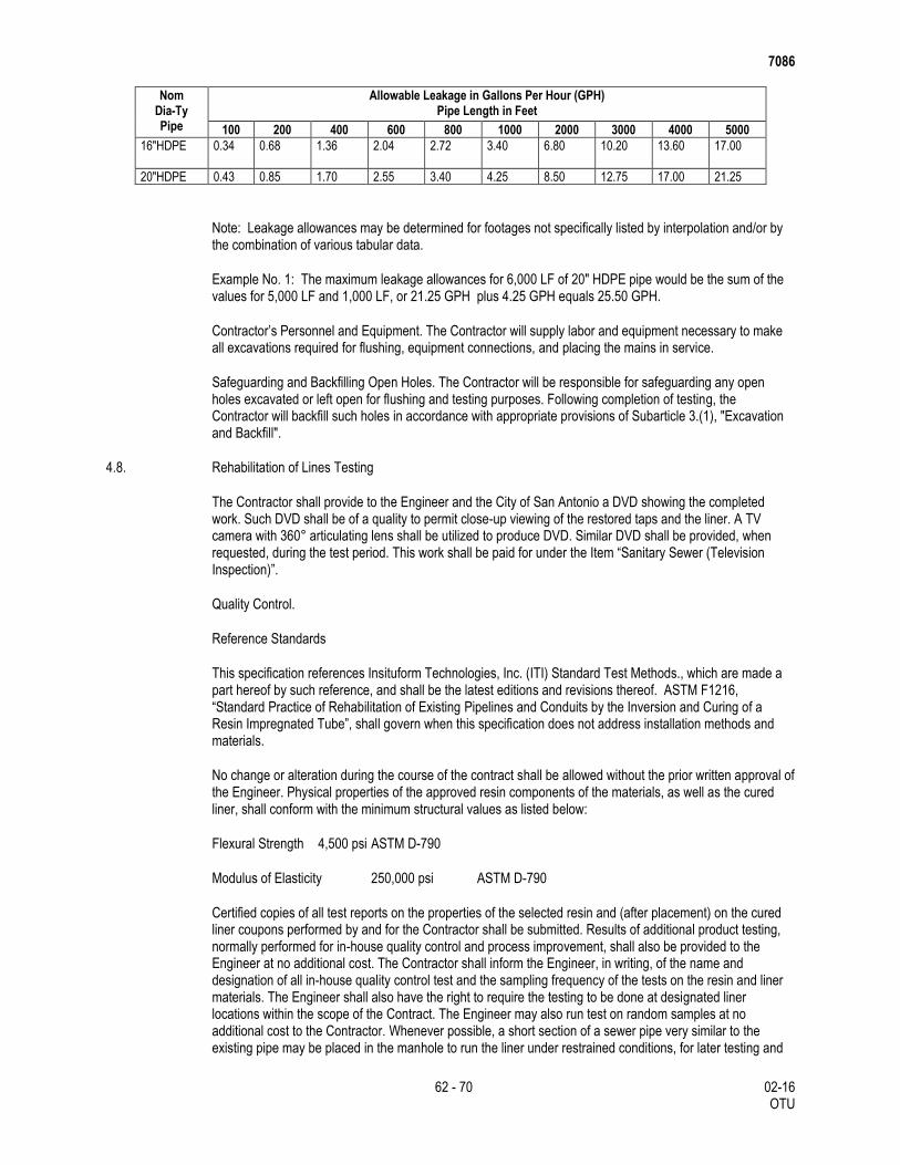
7086
62 - 70 02-16 OTU
Nom Dia-Ty Pipe
Allowable Leakage in Gallons Per Hour (GPH) Pipe Length in Feet
100 200 400 600 800 1000 2000 3000 4000 5000
16"HDPE 0.34 0.68 1.36 2.04 2.72 3.40 6.80 10.20 13.60 17.00
20"HDPE 0.43 0.85 1.70 2.55 3.40 4.25 8.50 12.75 17.00 21.25
Note: Leakage allowances may be determined for footages not specifically listed by interpolation and/or by the combination of various tabular data.
Example No. 1: The maximum leakage allowances for 6,000 LF of 20" HDPE pipe would be the sum of the values for 5,000 LF and 1,000 LF, or 21.25 GPH plus 4.25 GPH equals 25.50 GPH.
Contractor’s Personnel and Equipment. The Contractor will supply labor and equipment necessary to make all excavations required for flushing, equipment connections, and placing the mains in service.
Safeguarding and Backfilling Open Holes. The Contractor will be responsible for safeguarding any open holes excavated or left open for flushing and testing purposes. Following completion of testing, the Contractor will backfill such holes in accordance with appropriate provisions of Subarticle 3.(1), "Excavation and Backfill".
4.8. Rehabilitation of Lines Testing
The Contractor shall provide to the Engineer and the City of San Antonio a DVD showing the completed work. Such DVD shall be of a quality to permit close-up viewing of the restored taps and the liner. A TV camera with 360° articulating lens shall be utilized to produce DVD. Similar DVD shall be provided, when requested, during the test period. This work shall be paid for under the Item “Sanitary Sewer (Television Inspection)”.
Quality Control.
Reference Standards
This specification references Insituform Technologies, Inc. (ITI) Standard Test Methods., which are made a part hereof by such reference, and shall be the latest editions and revisions thereof. ASTM F1216, “Standard Practice of Rehabilitation of Existing Pipelines and Conduits by the Inversion and Curing of a Resin Impregnated Tube”, shall govern when this specification does not address installation methods and materials.
No change or alteration during the course of the contract shall be allowed without the prior written approval of the Engineer. Physical properties of the approved resin components of the materials, as well as the cured liner, shall conform with the minimum structural values as listed below:
Flexural Strength 4,500 psi ASTM D-790
Modulus of Elasticity 250,000 psi ASTM D-790
Certified copies of all test reports on the properties of the selected resin and (after placement) on the cured liner coupons performed by and for the Contractor shall be submitted. Results of additional product testing, normally performed for in-house quality control and process improvement, shall also be provided to the Engineer at no additional cost. The Contractor shall inform the Engineer, in writing, of the name and designation of all in-house quality control test and the sampling frequency of the tests on the resin and liner materials. The Engineer shall also have the right to require the testing to be done at designated liner locations within the scope of the Contract. The Engineer may also run test on random samples at no additional cost to the Contractor. Whenever possible, a short section of a sewer pipe very similar to the existing pipe may be placed in the manhole to run the liner under restrained conditions, for later testing and

7086
63 - 70 02-16 OTU
thickness measurements, at no additional payment. All samples shall be labeled before shipment for testing; and a duplicate piece shall also be provided, if requested, for inspection and testing by an independent laboratory, if required.
General Corrosion Requirements. The CIPP shall be fabricated from materials which when cured, will be chemically resistant to internal exposure to domestic sewage.
Water Analysis (Industrial Areas Only). In industrial areas where sewers are subject to possible organic and inorganic wastes other than normal domestic sewage, the Engineer shall obtain samples of the dry weather sewage for chemical content analysis. This analysis shall be supplied to the Contractor for their information.
Submittals. The Contractor shall submit, along with the bid proposal, a copy of the recommended pipe installation procedures, certified by the pipe manufacturer.
4.9. Pipe Bursting/Crushing Replacement Testing
After the existing sewer is completely replaced, internally inspect with television camera and DVD as required. The finished tape will be continuous over the entire length of the sewer between two manholes and to be free from visual defects.
Defects which may affect the integrity or strength of the pipe in the opinion of the Engineer will be repaired or the pipe replaced at the Contractor’s Expense.
The Contractor shall smoke test to verify all sewer service connections.
The following items are excerpted from TCEQ Chapter 317 requirements for gravity sewer construction testing (§317.a.4). Compliance with these requirements is required unless the Contractor obtains and provides written authorization from the TCEQ authorizing alternative testing and compliance procedures:
Testing of Installed Pipe. An infiltration, exfiltration or low-pressure air test shall be specified. Copies of all test results shall be made available to the executive director (TCEQ) upon request. Test shall conform to the following requirements:
Infiltration or Exfiltration Tests. The total exfiltration as determined by a hydrostatic head test, shall not exceed 50 gallons per inch diameter per mile of pipe per 24 hours at a minimum test head of 2-ft. above the crown of the pipe at the upstream manhole. When pipes are installed below the groundwater level an infiltration test shall be used in lieu of the exfiltration test. The total infiltration, as determined by a hydrostatic head test, shall not exceed 50 gallons per inch diameter per mile of pipe per 24 hours at a minimum test head of 2-ft. above the crown of the pipe at the upstream manhole, or at least 2-ft. above existing groundwater level, whichever is greater. For construction within the 25 year flood plain, the infiltration or exfiltration shall not exceed 10 gallons per inch diameter per mile of pipe per 24 hours at the same minimum test head. If the quantity of infiltration or exfiltration exceeds the maximum quantity of infiltration or exfiltration exceeds the maximum quantity specified, remedial action shall be undertaken in order to reduce the infiltration or exfiltration to an amount within the limits specified.
Low Pressure Air Test. Perform in accordance with requirements of this specification.
Deflection Testing. Perform in accordance with requirements of this specification.
Clean-up and Restoration. Any damage to existing utilities, structures, storm drain systems, curbs, sprinkler systems, mail boxes, driveway, etc., shall be repaired as directed. All repairs and replacements shall be made at the Contractor’s expense. Upon acceptance of the installation work and testing, the Contractor shall cleaN-up and restores the project area affected by operations. Daily clean-up of the project site to the satisfaction of the Engineer shall also be required.

7086
64 - 70 02-16 OTU
5. MEASUREMENT
Sewer Excavation and Non-stabilized Backfill
Sewer excavation and non-stabilized backfill will be measured in accordance with Item 400, “Excavation and Backfill for Structures” but will not be measured for payment and will be considered subsidiary to the sewer line installation.
Trench Excavation Protection
Trench excavation protection will be measured by the foot along the centerline of the trench where the depth exceeds 5-ft.
Sanitary Sewers
Longitudinal measurement of sanitary sewers will be made along the centerline of the sewer from center of manhole to center of manhole or end of main by the foot of the various sizes and types (when a specific type is required) of sewers shown on the plans, in accordance with this specification, complete and accepted.
One way cleanouts to be installed in all laterals at the customers property line and will be measured for payment by each installed.
Plugging existing sewer lines will be considered subsidiary to the pipe installation.
Sanitary Sewer Laterals
The lengths of laterals will be measured from the centerline of the sewer main to the connection at or within the customer’s property line or premises. Wyes, tees, and bends of any kind will not be paid for separately for laterals but will be measured for payment by the foot of lateral to be installed.
Jack, Boring or Tunneling
Jacking, Boring or Tunneling will be measured by the linear foot of bore or tunnel as measured from face to face of jacking pits.
Carrier pipe used in bores and tunnels or backed into place will be measured by the linear foot of pipe installed from end to end of pipe to the limits shown on the plans
Casing or liners, where required for plans of the size and material required will be measured by th linear foot actually installed in accordance with plans.
Vertical Stacks
Vertical Stacks will be measured by the linear feet. Footage will be measured from the finish grade elevation (centerline) minus invert elevation minus 8 feet.
Manhole Structures
Manholes structures will be measured by each manhole structure complete in place. Manhole structures will be installed where any pipe intercepted is larger than 24-inch in diameter. Rings and Watertight Covers, concrete ring encasement and I&I Barriers, will not be measured for payment, but will be considered subsidiary to the manhole.
Pre-Cast Manholes

7086
65 - 70 02-16 OTU
Manholes to 6 feet deep and designated on plan will be measured by each type manhole complete in place including those exceeding 6 feet in depth from the lowest invert elevation to the top of the ring. Rings and Watertight Covers, concrete ring encasement and I&I Barriers, will not be measured for payment, but will be considered subsidiary to the manhole.
Manholes deeper than 6 feet will be measured by the number of linear feet in excess of 6 ft.
Adjusted or Abandoned Manholes
Manholes adjusted or abandoned as prescribed herein, will be measured by each manhole. The excavation and backfill required and the I&I Barrier for Adjust Manholes will not be measured for payment, but will be considered subsidiary to this Item.
Select Backfill
Cement Stabilized Backfill will be measured by the cubic yard in accordance with the backfill diagram shown on the plans or as directed.
Flowable Backfill
Flowable Backfill will be measured by the cubic yard based on the dimensions and depths shown on the plans or as directed.
Select Bedding Material
Where directed to be used for rigid pipe installations, Select Bedding Material will be measured by the cubic yard as dimensioned on the plans. Select Bedding Material is always required for Flexible Pipe installation; therefore, it will not be measured for payment.
Concrete Encasement, Cradles, Saddles and Collars
Concrete encasement, cradles, saddles and collars for pipe will be measured by the cubic yard as dimensioned on the plans or as directed, complete in place. Reinforcing if required will not be measured.
Concrete Curb, Sidewalks, Driveways, Islands and Medians
For concrete curbs, sidewalks, driveways, islands and medians required to be removed and replaced due to placement of sewer lines, removal of the existing concrete will be measured by the foot or by the square yard as dimensioned and detailed on the plans.
Cut and Restore Pavement
The work to be done in the cutting and restoring of pavement will be measured by the square yard in accordance with the dimensions and details shown on the plans.
Removing and Replacing Chain-Link and/or Wire Fence
This work will be measured by the foot of fence removed and replaced, regardless of the type or height of the fence, complete in place. The existing fence materials may be reused unless, the existing materials were damaged during removal and should not be reused, the Contractor is to provide new material for the replacement work at his expense.
Abandon Sewer Lines
When shown on the plans, this work will be measured by linear foot complete in place.

7086
66 - 70 02-16 OTU
Television Inspection
This Item will be measured by the foot of main televised for TV inspection. The foot measurement will be determined as the distance from the center of sewer manhole to the center of sewer manhole.
Reconstruct Manholes
Manholes completely reconstructed as prescribed herein, will be measured by the unit of each manhole (any type or size), regardless of the type shown on the plans.
Automatic Air Release Valve
Automatic Air Release Valve will be measured as each assembly of the size installed.
Ductile-Iron Fittings
Ductile-Iron Fittings will be measured by the weight to the nearest one-hundredth of a ton of the various sizes installed.
Hydrostatic Pressure Test
Hydrostatic Pressure Test will be measured as each successful test conducted on sanitary sewer force mains only. Hydrostatic testing of manholes will not be measured for payment
Rehabilitation of Lines
This Item shall be measured by the foot, based on the measured distance of existing sanitary sewer line to be rehabilitated from centerline of manhole to centerline of manhole.
Point Repair
This Item will be measured on an each basis. The minimum length of pipe to be replaced at each repair locations shall be 9-ft. Measurement for sewer line extra length point repair is on a linear foot basis in excess of minimum replacement length.
By-Pass Pumping
This Item will be measured by the “Lump Sum” as the work progresses. No additional measurement or payment will be made for conditions caused by the Contractor during construction.
Rehabilitation of Manholes
This Item will be measured by the linear foot.
Cleaning Manhole and Mains
Sanitary sewer manhole and mainline cleaning will not be measured for payment and shall be subsidiary to rehabilitation of manholes and lines.
Sliplining.
Measurement for Sliplining is on a by foot basis for installed liner pipe, measure form center line of upstream manhole to center line of downstream manhole. Depth range for payment is based on depth measured at sewer main from natural ground level to flow line of sanitary sewer for each pipeline segment.

7086
67 - 70 02-16 OTU
6. PAYMENT
Sewer Excavation. Payment for sewer excavation and non-stabilized backfilling in accordance with these specifications will not be paid for directly but will be included in the unit price bid for the sanitary sewer pipe installation. Select bedding and stabilized backfill will be paid for under their own items of work.
Trench Excavation Protection. Payment will be made at the unit price bid for “Sanitary Sewer (Trench Excavation Protection)” in place. This price shall be full compensation for all labor, equipment, materials, tools,all components of the trench protection system which can include but not limited to sloping, sheeting, trench boxes or trench shields, sheet piling, cribbing, bracing, shoring, dewatering/diversion of water to provide adequate/acceptable drainage, any additional excavation or backfill required, jacking, jack removal, removal of the trench support after completion and all other labor, materials, tools, equipment and incidentals necessary to complete the work.
Sanitary Sewers. Payment will be made at the unit price bid shall be full compensation for all labor, equipment, materials, tools, and incidentals for “Sanitary Sewers” of the size, and type (when a specific type is required) specified on the plans complete in place.
Sanitary sewer force mains will be paid for at the unit price bid shall be full compensation for all labor, equipment, materials, tools, and incidentals for “Sanitary Sewers (Force Main)” of the size and type specified on the plans, complete in place.
Sanitary sewer service connections will be paid for at the unit price bid which shall be full compensation for all labor, equipment, materials, tools, and incidentals for “Sanitary Sewers Lateral Pipe)” of the size specified per linear foot complete in place.
Sanitary Sewer Laterals. Payment will be made at the unit price bid shall be full compensation for all labor, equipment, materials, tools, and incidentals for “Sanitary Sewer Lateral” of the size and type (when a specific type is required) specified on the plans per linear foot complete in place.
Jacking, Boring or Tunneling. Jacking, Boring or Tunneling will be paid for at the contract unit price bid per linear foot of jacking, boring or tunneling, which price shall be full compensation for furnishing all materials (except carrier pipe, casings or liners), labor, tools, equipment and incidentals necessary to complete the work, including excavation, grouting, backfilling, restoration to original ground conditions, and disposal of surplus materials.
Carrier pipe shall be paid for at the contract unit price bid which shall be full compensation for "Carrier Pipe for Jacking, Boring or Tunneling" per linear foot of pipe installed and measured as prescribed above.
Casings or liners shall be paid for at the contract unit price bid which shall be full compensation for "Casing or Liner" per linear foot of casing or liner installed and measured as prescribed above.
Vertical Stacks. Payment will be made at the unit price bid per linear foot which shall be full compensation for all labor, equipment, materials, tools, and incidentals complete in place.
Sanitary Sewer Cleanouts. Payment will be made at the unit bid price for “Sanitary Sewer Cleanout” of the size and type (when a specific type is required) specified on the plans which shall be full compensation for all labor, equipment, materials, tools, and incidentals complete in place.
Manhole Structures. Payment for Manholes structures, including the stack, rings, watertight covers, steps and concrete ring encasement, I&I Barriers, will be made at the unit price bid for “Sanitary Sewer Manhole Structure (Complete) of the type specified which shall be full compensation for all labor, equipment, materials, tools, and incidentals.
Pre-Cast Manholes. Payment for Pre-Cast manholes, including the stack, rings, watertight covers, steps and concrete ring encasement, I&I Barriers, will be made at the unit price bid for “Sanitary Sewer Pre-Cast

7086
68 - 70 02-16 OTU
Manhole (Complete)” of the type specified which shall be full compensation for all labor, equipment, materials, tools, and incidentals.
Payment for Extra depth manholes will be made at the unit price bid per linear foot as measured.
Abandon or Adjust Manholes. Manholes abandoned or adjusted will be paid for at the unit price bid for “Sanitary Sewer (Abandon Manhole)” or “Sanitary Sewer (Adjust Manhole)” which shall be full compensation for all labor, equipment, materials, tools, and incidentals to complete the work.
Select Backfill.
Cement Stabilized Backfill. Payment will be made for “Cement Stabilized Backfill” at the unit price bid for “Sanitary Sewer (Cement Stabilized Backfill)” which shall be full compensation for all labor, equipment, materials, tools, and incidentals to complete the work..
Flowable Backfill. Payment for “Flowable Backfill” will be made at the unit price bid for “Sanitary Sewer (Flowable Backfill)” which shall be full compensation for all labor, equipment, materials, tools, and incidentals to complete the work..
Select Bedding Material. Payment for “Select Bedding Material” for rigid pipe installations will be made at the unit price bid for “Sanitary Sewer (Select Bedding)”. The select bedding for flexible pipes will not be paid for directly but will be subsidiary to the flexible pipe.
Concrete Encasement, Cradles, Saddles and Collars. Payment will be made at the unit price bid for “Sanitary Sewers (Concrete Encasement, Concrete Cradles, Concrete Saddles and Concrete Collars)” which shall be full compensation for all labor, equipment, materials, tools, and incidentals to complete the work..
Concrete Curbs, Driveways, Sidewalks, Islands or Medians. Payment for replacement of curbs, driveways, sidewalks, islands and medians will be made at the unit price bid for “Sanitary Sewers (Concrete Sidewalk)”, “Sanitary Sewers (Concrete Driveway)”, “Sanitary Sewers (Concrete Islands)”, “Sanitary Sewers (Concrete Medians)” and “Sanitary Sewer (Concrete Curb)” which shall be full compensation for all labor, equipment, materials, tools, and incidentals to complete the work..
Cut and Restore Pavement. Payment will be made at the unit price bid for “Sanitary Sewers (Cut and Restore Pavement)” which shall be full compensation for all labor, equipment, materials, tools, and incidentals to complete the work..
Remove and Replace Chain-Link and/or Wire Fence. Payment will be made at the unit price bid for “Sanitary Sewer (Remove and Replace Fence)” which shall be full compensation for all labor, equipment, materials, tools, and incidentals to complete the work..
Abandon Sewer Lines. Payment will be made at the unit price bid for “Sanitary Sewer (Abandon Pipe)” of the size shown on the plans which shall be full compensation for all labor, equipment, materials, tools, and incidentals to complete the work..
Television Inspection. The work performed and materials furnished in accordance with this Item and measured as provided under “Measurement” will be paid for at the unit price bid for “Sanitary Sewer (Television Inspection).” This price shall be full compensation all labor, materials, equipment, tools, logging, and all incidentals necessary to complete the work.
Testing Sanitary Sewers for leakage, including all labor, materials, and equipment necessary to perform the tests, will not be paid for directly but will be considered incidental to the various Sanitary Sewer pay items.
Reconstruct Manholes. Payment for reconstructed manholes, complete in place will be made at the unit price bid for “Sanitary Sewer (Reconstruct Manhole)” which shall be full compensation for all labor, equipment, materials, tools, and incidentals to complete the work...

7086
69 - 70 02-16 OTU
Automatic Air Release Valve. Payment for “Automatic Air Release Valve” will be made at the unit price bid for “Sanitary Sewer (Automatic Air Release Valve)(Complete)” and will be full compensation for each assembly of the various sizes installed in accordance with the details shown on the plans. This payment will also include selected embedment material, anti-corrosion embedment when specified, blocking and various sizes and types of meter boxes.
Ductile-Iron Fittings. Payment for “Ductile-Iron Fittings” will be made at the unit price bid for “Sanitary Sewer (Ductile-Iron Fittings)” and will be full compensation for each ton of fittings of all sizes and types installed and will be based upon the weights of fittings shown in the “Weights of Ductile-Iron and Cast-Iron Fittings” table.
Hydrostatic Pressure Test. Payment made for “Hydrostatic Pressure Test” will be made at the unit price bid for “Sanitary Sewer (Hydrostatic Pressure Test)” and will be full compensation for each successful test conducted on sanitary sewer force mains only. No direct payment will be made for hydrostatic testing manholes.
No direct payment will be made for concrete blocking of sanitary sewer force mains; furnishing and installing the joint restraint system; coating and wrapping pipe joints; polyethylene wrapping; trench excavation below specified limits; excavation and removal of unsuitable material at bottom of trench grade and restoration with approved material; supporting pipe or conduits of public utilities; and flushing sanitary sewer force mains. This work will be considered subsidiary to the various bid items.
Rehabilitation of Lines. The work performed and materials furnished in accordance with this Item and measured as provided under ‘Measurement”, will be paid for at the unit price for “Sanitary Sewer (Line Rehabilitation)”. This price shall be full compensation for all labor, equipment, materials, tools, pre-rehabilitation line cleaning, water, clean-up, dump sites and hauling of debris, labor, materials and equipment used in replacing bases and pavements, access to right-of-ways and easements as necessary, removal of equipment due to bad ground or poor pipe conditions, and other incidentals necessary to complete the work for either method of sanitary sewer line rehabilitation.
Point Repair. The work performed and materials furnished in accordance with this Item and measured under “Measurement” will be paid for at the unit price bid for “Sanitary Sewer (Point Repair)”, for sizes and types constructed (when a specific type is required), regardless of depth. This price shall include all materials, including pipe, trenching, pumping, shoring and bracing, sand cushion, concrete plugs, laying and jointing, backfilling, tapping, water, labor, tools, equipment, pavement work and all incidentals necessary to complete the work.
Payment for sewer line extra length will be in accordance with this Item and measured under “Measurement” will be paid for at the unit price bid for “Sanitary Sewer (Point Repair sewer line extra length)”, for sizes and types constructed (when a specific type is required), regardless of depth. This price shall include all materials, including pipe, trenching, pumping, shoring and bracing, sand cushion, concrete plugs, laying and jointing, backfilling, tapping, water, labor, tools, equipment, pavement work and all incidentals necessary to complete the work.
By-Pass Pumping. The work performed and material furnished in accordance with this Item and measured as provided under “Measurement” will be paid for the unit price bid for “Sanitary Sewer (By-Pass Pumping)”. Partial payments of this “Lump Sum” bid will be as follows:
When initial set-up and operation of the bypass system begins, 40% of the line item will be paid.
The remaining portion of the line item will be paid when the bypass pumping operations for the entire job are completed.
Rehabilitation of Manholes. The work performed and materials furnished in accordance with this Item and measured as provided under “Measurement”, will be paid for at the unit price bid for “Sanitary Sewer (Manhole Rehabilitation)”. This price shall be full compensation for materials, labor, equipment, tools, testing and all incidentals necessary to complete the work.
7086
70 - 70 02-16 OTU
Cleaning Manholes and Mains. All work described by this Item shall be subsidiary rehabilitation of manholes and lines
Pipe Bursting/Crushing Replacement.
The inserted pipe will be paid for per foot of pipe installed using pipe-bursting/crushing method for the pipe diameter, type, quantity, and depth specified and shall be full compensation for all labor, equipment, materials, tools, incidentals, all pipe installation materials, all submittals, sealing materials at manholes and annulus (if required), launching pits, receiving pits, post testing, shoring, bedding, backfill, and all necessary, corresponding, and related work specified herein.
Services. Locating and reconstruction of services and all connections of services will be paid for per each connection made, which shall be full compensation for all labor, equipment, materials, tools, and incidentals to complete the work, including fittings and pipe. Payment for abandoned services will be on as per each connection made basis.
Point Repairs. Point repairs will be paid for on as per each basis, as needed which shall be full compensation for all labor, equipment, materials, tools, and incidentals to complete the work... Extra length point repair will be paid based on the length of pipe replaced per repair beyond the length established for each single point repair item, as needed. Abandoned point repairs will be paid on a cubic yard basis, as needed.
Obstruction Removal. Obstruction removal will be paid for on as per each basis, as needed which shall be full compensation for all labor, equipment, materials, tools, and incidentals to complete the work...
Storm Water Pollution Prevention and Erosion Control Plan. Payment for this item will be based on the items and quantities of control measures included in the proposal on the basis indicated in the respective specification sections.
Site Restoration. Except as associated with point repairs and obstruction removals, site restoration for all impacts to surface improvements will be on a foot basis of the rehabilitated line segment. For point repairs and obstruction removals, site repair will be on as per each basis.
Television Inspection. Payment will be made for television inspection of the sewer line prior to pipe rehabilitation in accordance with this specification. There will be no additional or separate payment for “post-TV” video inspection, documentation, required submittals, and associated or related work.
By-Pass Pumping. The cost of any necessary by-pass pumping will be considered subsidiary to the appropriate pay items for pipe installation, television inspection, repair, or related work and will not be a separate pay item.
Sliplining.
Payment will be made at the unit price bid shall be full compensation for all labor, equipment, materials, tools, and incidentals for “Sliplining” of the size and type (when a specific type is required) specified on the plans per linear foot complete in place.
Insertion pits, access pits, clamp installation, embedment (bedding, haunching and initial backfill), field quality control (testing), sealing liner at manholes, grouting annular space, building up, shaping and reworking manhole inverts and benches, and pre-installation and post-installation cleaning and television inspection of completed work are included in sliplining unit price and not paid for separately.
Excavations initially begun as obstruction removals or point repairs which the Contractor later decides to use as insertion pits are considered as insertion pits and not paid for separately.
Trench safety systems, well pointing and other applicable bid items associated with insertion pits will be paid for at their respective contract unit prices.