Special High Voltage Protection
56
CenturyLink Inc. Technical Publication Protection of CenturyLink Facilities Serving Electrical Supply Locations Formerly known as “Special High Voltage Protection” Copyright 1988, 2013, 2014, 2016 Printed in U.S.A All Rights Reserved PUB 77321 Issue D July 2016
-
Upload
duongthien -
Category
Documents
-
view
225 -
download
0
Transcript of Special High Voltage Protection

CenturyLink Inc. Technical Publication
Protection of CenturyLink Facilities Serving Electrical
Supply Locations
Formerly known as “Special High Voltage Protection”
Copyright 1988, 2013, 2014,
2016
Printed in U.S.A All Rights Reserved
PUB 77321 Issue D July 2016

PUB 77321 Issue D, July 2016
NOTICE
This publication describes telecommunication services provided by CenturyLink that extend into high voltage locations. Services that enter high voltage locations may require special protection.
CenturyLink assumes no responsibility for any costs incurred by a supplier in conforming to the contents of this publication. Further, conformance to this publication does not constitute a guarantee of a given supplier's equipment and/or its associated documentation.
CenturyLink reserves the right, without prior notice, to revise this publication for any reason.
Throughout this publication, the term CenturyLink signifies CenturyLink Inc.

PUB 77321 Issue D July 2016
PLEASE TEAR OUT AND SEND YOUR COMMENTS/SUGGESTIONS TO:
CenturyLink Local Network Electrical Protection Tech Support 700
W. Mineral, MT00-G22.31 Littleton, CO 80210
(303) 707-5800 Fax: (303) 707 9041
Comments
[email protected];[email protected];[email protected]
Information from you helps us to improve our Publications. Please take a few moments to answer the following questions and return to the above address.
Was this Publication valuable to you in determining our requirements?
YES
NO
Was the information accurate and up-to-date? YES NO
Was the information easily understood? YES NO
Were the contents logically sequenced? YES NO
Were the printed pages legible? YES NO
Do you feel the description in the Catalog of Technical Information and/or Digest of Technical Information adequately described this Publication?
YES
NO
If you answered NO to any of the questions and/or if you have any other comments or suggestions, please explain:
(Attach additional sheet, if necessary)
Name Date
Company
Address
Telephone Number

PUB 77321 Issue D, July 2016
1
Table of Contents:
1.0 Introduction
1.1. General
1.2. Purpose
2.0 Responsibilities –
2.1 Responsibility of CenturyLink
2.1.1 CenturyLink Owned High Voltage Protection Equipment
2.2 Responsibility of the Customer Requesting Service
2.2.1 Additional Responsibilities
2.2.2 Customer Owned High Voltage Protection Equipment
2.3 Responsibility of Owner of Record
3.0 State Tariffs
3.1 Special Construction Cost
4.0 Protection Service Types
4.1 Service Performance Objective Classifications
4.2 Service Offerings
5.0 Form RG31-0048

PUB 77321 Issue D, July 2016
2
6.0 Ground Potential Rise (GPR) and Zone of Influence (ZOI)
6.1 Overview
6.2 Ground Potential Rise
6.3 Zone of Influence
6.4 Peak Asymmetrical Voltage
6.4.1 Peak Asymmetrical Voltage Formula
6.5 Ground Potential Distribution fFrom the Edge of High Voltage Location (substations etc.) Ground Grid With Respect to Remote Earth
7.0 High Dielectric Strength Copper Cable and High Voltage Protection
7.1 CenturyLink Provided High Voltage Protection
7.2 Customer Provided High Voltage Protection
8.0 Optical Fiber Facilities
8.1 CenturyLink Provided Optical Fiber System
8.1.1 Central Office or Remote Electronic Cabinet Based System
8.1.1.1 Equipment Powering
8.1.2 Copper to Fiber Hybrid System
8.2 Customer Provided Optical Fiber System
8.2.1 Point to Point or Optical Fiber Handoff
8.2.2 Customer Provided Copper to Fiber Hybrid System
9.0 Acronyms

PUB 77321 Issue D, July 2016
3
10.0 References
10.1 IEEE
10.2 Exhibits

PUB 77321 Issue D, July 2016
4
1.0 Introduction
1.1 General This document describes telecommunications services and facility designs provided by CenturyLink that extend into high voltage locations. High voltage locations may include services directed into power generation facilities, substations, cell sites residing on substation ground grids, cell sites in close proximity to substations, and cell sites residing on high voltage transmission towers. This special high voltage protection, as designed by CenturyLink, will provide personnel and equipment safety while insuring the continuity of service. The provision of these services generally follows the recommendations of ANSI/ IEEE STD 487™ "IEEE Guide for the Electrical Protection of Communication Facilities Serving Electric Power Stations"© and ANSI/ IEEE STD 1590™ "IEEE Recommended Practice for the Protection of Communication Facilities Serving Electric Supply Locations Using Optical Fiber Systems"©
IEEE-487 2007™ defines:
3.1.6 Electric supply locations: Any building, separate space, or site in which electric supply equipment is located that may be subjected to the effects of ground potential rise (GPR). This includes generation, transformation, conversion, switching, and delivery facilities. 3.1.12 high-voltage environment (HVE): A location requiring caution because it may experience a ground potential rise (GPR) from power line fault currents.

PUB 77321 Issue D, July 2016
5
1.2 Purpose
The purpose of this document is to describe telecommunication service types provided on CenturyLink facilities that extend into high voltage locations and any design requirements for high voltage protection. These services will require high voltage protection whenever hazardous voltages of 1000V peak- asymmetrical or greater appear on those facilities due to ground potential rise (GPR) and/ or induction caused by faults in the customer's electric power system. Special high voltage protection is designed to isolate or neutralize hazardous voltages. The protection objectives on CenturyLink services and facilities at these locations are as follows:
• To minimize electrical hazards to personnel engaged in construction, operation, maintenance and use of telecommunications services.
• To limit electrical damage to telecommunications equipment, cable and wire facilities.
• To provide the required service continuity and integrity of telecommunication transmission as specified by the customer and approved by a CenturyLink Electrical Protection Engineer.
NOTE: This offering requires special high voltage protection at the customer's premises and may require special high voltage protection at the CenturyLink Central Office whenever the fault-produced GPR/ induction equals or exceeds 1000 volts peak-asymmetrical.

PUB 77321 Issue D, July 2016
6
2.0 Responsibilities
2.1 Responsibility of CenturyLink CenturyLink, working in conjunction with the customer, shall determine the proper methods of protection required to achieve the objectives set forth in Section 4 (Protection Service Types). The method of protection for all service requests in these specific locations shall be coordinated by CenturyLink, and must be compatible with the protection provided for the most critically important service at that location. See Section 4.2 ALL services/circuits provided by CenturyLink that terminate in a high voltage location must be protected by specialized high voltage protection equipment, regardless of circuit ownership It is expressly declared that metallic facilities are in continually decreasing supply, and CenturyLink is not obligated to continue to make such facilities available. Metallic facilities are offered only where existing facilities and operating conditions permit.
As of January 1st, 2015, where CenturyLink provides the high voltage isolation for all newly constructed high voltage locations, where CenturyLink provides the high voltage isolation, will only be served using an all-dielectric optical fiber cable.
CenturyLink reserves the right to treat special high voltage protection on an individual case basis, dependent on the type of facilities available.
Note: CenturyLink reserves the right to Lock-Out/ Tag -Out (a safety procedure used in the industry that requires hazardous conditions to be "isolate") any high voltage site it deems to be unsafe for any reason pending a review by a CenturyLink Electrical Protection Engineer. This is to ensure the safety of CenturyLink and customer personnel who work on the telecommunication facilities serving the high voltage location. CenturyLink also reserves the right to suspend any service without adequate special high voltage protection until adequate protection is provided.
2.1.1 CenturyLink Owned High Voltage Protection Equipment In states where tariffs have provisions for high voltage protection, the customer requesting service may request CenturyLink to provide the high voltage protection equipment. CenturyLink will install a complete high voltage protection service delivery facility. CenturyLink will maintain these facilities fully for the life of the telecommunication circuit(s) serving the electrical supply location or the co-located wireless provider.

PUB 77321 Issue D, July 2016
7
2.2 Responsibility of the Customer Requesting Service
The customer shall be responsible for providing to CenturyLink a completed Form RG31-0048, "Request for Electrical Information for Electrical Supply Locations," (see Exhibit 5-1, pages 1-2, on pages 29-30 of this document which includes the following):
Exhibit 5-1, page 1is the front of Form RG31-0048 with
numbered blocks used for directions on how it is to be completed.
Exhibit 5-1, page 2 is the instructions for filling out Form RG31-0048.
Note: The Form RG31-0048 shall be signed by an authorized power company representative for the high voltage location or a licensed electrical PE in the state the site is located.
2.2.1 Additional Responsibilities
The customer requesting service shall be required to provide • A non metallic conduit structure from the high voltage location
to the public right of way and at least 10 feet beyond the location ground grid.
• An equipment mounting platform (non-metallic NEMA cabinet, plywood back board, H Frame, etc).
• Local power from DC batteries or local AC power from a UPS or inverter system.
• A local ground source.
2.2.2 Customer Owned High Voltage Protection Equipment The customer requesting service, working with the owner of record, may provide the high voltage protection equipment. A fiber optic based facility is CenturyLinks preferred method of protection. For any hybrid fiber optic based facilities, CenturyLink will meet the customer outside the calculated 300 volt point of the zone of influence. This meet point will be considered the Demarc for this location. (See Section 8 of this document for complete details.) For copper based facilities, CenturyLink will place a high dielectric strength copper cable, associated cable termination equipment and may interposition the service extended Demarc.

PUB 77321 Issue D, July 2016
8
For outdoor applications, the customer may purchase and place a turnkey environmental cabinet equipped with a lightning arrestor and high voltage isolation jack panel. In this case CenturyLink will place the high dielectric strength copper cable and terminate the cable to the isolation jack panel. The jack panel will serve as a high voltage test point and main Demarc. An extended Demarc point may be interpositioned on the station side of the customers high voltage interface for services at this location.
Note: For all customer provided high voltage protection equipment CenturyLink only offers Class “C” service due to CenturyLink not having end to end ownership and responsibility.
2.3 Responsibility of Owner of Record
The structure owner is considered the “Owner of Record” for all telecommunication services delivered to a high voltage site. All service provision requirements directed to the site regardless of circuit ownership, such as a sub lease tenant, is the responsibility of the owner of record. Wireless providers collocated in or near a high voltage site may have the same responsibilities as the Owner of Record Many state tariffs mandate any changes in an electrical supply location will require written notification from the location owner, along with a revised Form RG31-0048. These changes shall be provided as they occur to permit reevaluation and redesign of the existing high voltage protection.
3.0 State Tariffs Some state tariffs provide for additional billing for circuits terminating in high voltage locations. These costs will be a monthly surcharge placed on each circuit requiring high voltage protection provided by CenturyLink. In most cases, customer provided high voltage isolation equipment will not be subject to any additional surcharges. For customer provided hybrid optical fiber systems that are line powered, there may be an additional monthly surcharge for providing this line power. There are several states within CenturyLinks serving territory that have tariffs specific to high voltage protection surcharges. For access to CenturyLink Tariffs, click HERE
3.1 Special Construction Cost: Every state tariff has provisions for special construction costs. The CenturyLink engineer having responsibility for the electrical supply location will determine any special construction costs applicable for placing facilities into any location requiring high voltage protection. Special construction costs may be assessed for new construction, re-termination or re-arrangements of facilities.

PUB 77321 Issue D, July 2016
9
4.0 Protection Service Types
Protection services which CenturyLink offers are identified according to the following types:
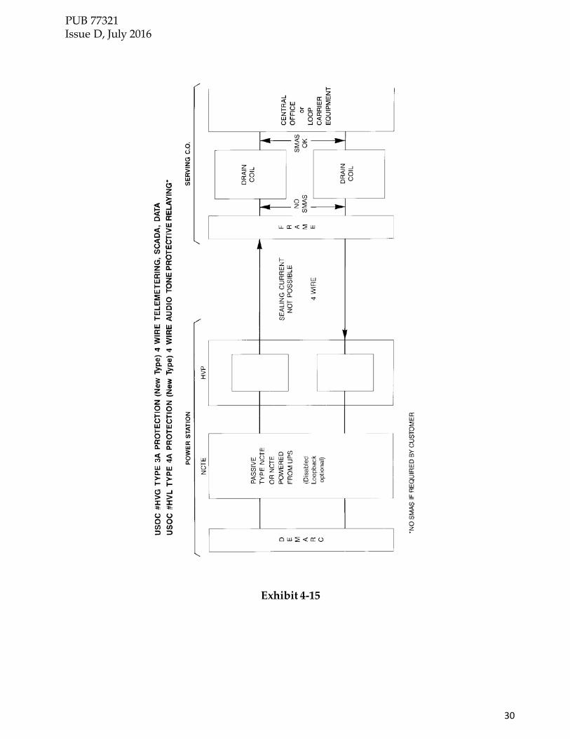
Type 1 - Services requiring either DC transmission or AC and DC transmission, used for Basic Exchange Telephone Service and/ or Private Line Access Service (DDS, ADSL) Type 2 - Private Line Access Service requiring (AC/DC) voice band or (DC) narrowband transmission, used for pilot wire protective relaying or (DC) tripping respectively. Type 3 - Private Line Access Service requiring (AC) voice band/ data transmission only, used for tele-metering, supervisory control, data, etc. Type 4 - Private Line Access Service requiring (AC) voice band transmission only, used for audio tone protective relaying.
4.1 Service Performance Objective Classifications
Interruptions or outages of telecommunications circuits serving electric supply locations (substations etc) may occur for physical reasons such as cable damage due to extraordinary heavy storm loading, a vehicle striking and breaking a utility pole, a cable cut, a lightning strike, or any other man made or natural disaster. Circuit failures caused by manmade/natural events cannot be prevented and CenturyLink expressly states that provision of the service provided in this section cannot preclude such service outages. Interruptions or outages due to the effects of ground potential rise (GPR) in the customer's power generating, transmission and/ or distribution systems are minimized through the installation and maintenance of high voltage protection service which is designed to operate in a fault- produced electrical environment. Service performance objective (SPO) classifications have been established for the purpose of permitting the customer to specify the performance objectives for most types of telecommunications services provided to power stations. SPO classifications are offered to provide various degrees of service continuity during power system faults.

PUB 77321 Issue D, July 2016
10
SPO Classifications are:
Class A - Non-interruptible service performance (must function before, during and after the power fault condition) for services requiring AC transmission only. Class A service cannot tolerate even a momentary service interruption. Non- tolerable service interruptions include both loss of dependability (failure to deliver a valid trip or control signal) and loss of security (delivery of a false trip or control signal). Class B - Self-restoring interruptible service performance (must function before and after the power fault condition) for any service. Class B service can tolerate a service interruption for the duration of a power system fault but service continuity must be restored immediately after the fault without requiring any repair personnel activity. Class C - Normal service which does not require special high voltage protection. Interruptible service performance (can tolerate a station visit to restore service) for power stations with a GPR less than 1000V peak-asymmetrical. Class C service cannot be provided in conjunction with Class A or Class B service.
Note: For all customer provided high voltage protection equipment CenturyLink only offers Class “C” service due to CenturyLink not having end to end ownership and responsibility.
Note: Class ‘A’ circuits should originate and terminate within the same wire center. Class ‘A’ circuits may be transmitted on digital and or fiber optic facilities which may introduce latency issues and time delays on circuit tripping. CenturyLink no longer offers Class A service on new circuit requests.

PUB 77321 Issue D, July 2016
11
DEFINITIONS CLASS A OR B SERVICE
SERVICE TYPE AND PERFORMANCE OBLECTIVE CLASSIFICATION/ USOC* FOR COPPER CABLE BASED SERVICE DELIVERY *TYPE or service refers to circuit usage *CLASS of service refers to reliability of HVP during a power fault
TYPE 1 CLASS B SERVICE (Phone, Tie Trunks, Trunks, Radio Control, DC Alarms, Telegraph, ISDN,
DDS and ADSL) All circuits used for talking and ADSL plus DC telemetering and telegraph.
Services which require both AC and/ or DC transmission and which can tolerate momentary interruptions during a power fault. (Must function before and after a power fault)
2 Wire USOC HVC 4 wire USOC HVD #4 Wire USOC HVA TYPE 2 CLASS B SERVICE (DC Tripping, Pilot Wire Relay) (Class A performance not available)
Normally a metallic cable pair end to end, but it can be a DC telegraph channel. (Metallic facilities are offered where existing facilities and operating conditions permit.)
Services which require both AC and/ or DC transmission and which can tolerate momentary interruptions during a power fault. (Must function before and after a power fault)
2 Wire USOC HVE #4 Wire USOC HVB TYPE, 3 CLASS A SERVICE (Data, Telemetering, SCADA)
Critical non type 4 circuits which require class A performance Service for AC transmission only which cannot tolerate even momentary interruption (Must function before, during and after a power fault.)
2 Wire USOC HVF 4 Wire USOC HVG TYPE, 3 CLASS B SERVICE (Data, Telemetering, SCADA)
All tone signals 300 Hz to 5 MHz and high capacity Digital (DS-1 Rate) Services for AC transmission only which can tolerate momentary interruptions (Must function before and after a fault)
2 Wire USOC HVH 4 Wire USOC HVJ TYPE, 4 CLASS A SERVICE (Audio Tone Protective Relaying)
Protective Relaying or Transfer Trip only (Voice Grade 12 when intralata) Service for AC transmission only which cannot tolerate even momentary interruption (Must function before, during and after a power fault.)
2 Wire USOC HVK 4 Wire USOC HVL
# Services limited to maximum ground potential rise (GPR) of 4 KV RMS-11 VS. (Refer to Electrical Protection Engineer before selecting.)
CLASS C SERVICE
Interruptible service performance (can tolerate visit to restore service). If ground potential rise (GPR) is less than 1000 volts peak-asymmetrical, no protection is required and Class C service may be requested. This shall be determined by an Electrical Protection Engineer
Exhibit 4-1 Design Information for Power Industry Channels

PUB 77321 Issue D, July 2016
12
USOC’S FOR OPTICAL FIBER BASED SERVICE
P1QXF: CENTURYLINK PROVIDED FIBER TRANSPORT SYSTEM OPTICAL
ETHERNET OR DS-3 LEVEL SERVICE DELIVERY P1QTA: CENTURYLINK PROVIDED FIBER PROTECTION ISOLATION EQUIPMENT
SERVING HIGH VOLTAGE LOCATIONS - USING HYBRID OR ALL DIELECTRIC FIBER FOR NON-FIBER BASED SERVICES
VPQ: PROTECTION ISOLATION EQUIPMENT - CUSTOMER PROVIDED FIBER
VPQSP: HIGH VOLTAGE PROTECTION EQUIPMENT - CUSTOMER PROVIDED FIBER
- SPAN POWER - CO TO CPE ELECTRICAL TO OPTICAL CONVERSION EQUIPMENT - DS1 SERVICE ONLY, OVER METALLIC FACILITIES
DM2EB: MISCELLANEOUS DATA EQUIPMENT - ENVIRONMENTAL CABINET
Note: Any services delivered utilizing a CenturyLink provided hybrid fiber system may have both copper cable based and fiber based USOCs applied to each circuit.
Exhibit 4-1 (continued) Design Information for Power Industry Channels
4.2 Service Offerings
The following customer option matrix identifies intra-lata service offerings with service performance objective classifications and the associated universal service order code (USOC).

17
PUB 77321 Issue D, July 2016
TYPE/ CLASS
SERVICE CODES
USOC (NOTES 1 & 2)
HVA HVB HVC HVD HVE HVF HVG HVH HVJ HVK HVL
1 LS X 1 BA X 1 SG X 1 CS X 2 PV X X 2 PW X X 1 TC X X 1 TT X X 3 PA X X 1 PL X X 1 RT X X 3 VM X X 3 VM X X 1 OS X 1 IT X 1 TA X 1 TL X 3 FD X X 3 FD X X 4 PR X X 3 S S X X 3 S S X X 1 LA X 3 MT X 1 DP X X 1 DQ X X 1 DR X X 1 DW X X 3 DA X 1 FX X 1 FT X 1 OP X 3 DH X 1 UC X X 1 UD X X 3 UE X 3 UG X X 3 UG X X
3 B UH X 1 US X X 1 UY X X 1 UZ X X 1 YB X 1 YG X 1 IB X
Figure 4-2 Intralata Service Offerings Matrix (1 of 2)

18
PUB 77321 Issue D, July 2016
N- Not available for all applications. This is applied on an individual case basis. X Available USOCs for these services. NOTE 1: The following USOCs are used with 2-Wire services: HVC, HVE,
HVF, HVH and HVK. The remaining USOCs are used with 4-Wire services.
NOTE 2: USOC codes HVA and HVB are limited to services with a maximum ground potential rise of 4.0 kV RMS and a maximum accumulated volt second requirement of 11.
NOTE 3: C and D conditioning options are not affected by high voltage protection. NOTE 4: Not all available service codes are on this list. Other services and special
assemblies will be handled on an individual case basis.
Figure 4-2 Intralata Service Offerings Matrix (2 of 2)

PUB 77321 Issue D, July 2016
19
The following customer option matrix identifies inter-lata service offerings with service performance objective classifications and the associated universal service order code (USOC).
TYPE/ CLASS
SERVICE
SERVICE DESIGNATOR
CODES (SERVICE
CODE)
USOC (NOTES 1 & 2)
HVA HVB HVC HVD HVE HVF HVG HVH HVJ HVK HVL
1B VG1 (LB) X X 1B VG2 (LC) S X X 1B VG3 (LD) S X X 1B VG4 (LE) X 3A VG5 (LF) X X 3B VG5 (LF) X X 3A VG6 (LG) X 3B VG6 (LG) X 1B VG7 (LH) S X X 1B VG8 (LJ) S S S 1B VG9 (LK) S X 3A VG10 (LN) X X 3B VG10 (LN) X X 3A VG11 (LP) X X 3B VG11 (LP) X X 4A VG12 (LR) X X 1B VGW (SE/SF) S S S 3B VGB (LZ) X X 1B LS1 (NT) X 1B LS2 (NU) X 2B MT3 (NV) X 1B TG1 (NW) X X 1B TG2 (NY) X X 1B FGA (SB) S S S 1B FGB (SD) S S S 1B FGC (Msg Tk) S S S 1B FGD (Msg Tk) S S S 1B AP1 (PE) X 1B AP2 (PF) X 1B AP3 (PJ) X 1B AP4 (PK) X 1B DA1 (XA) X X 1B DA2 (XB) X X 1B DA3 (XG) X X 1B DA4 (XH) X X 1B DA6 (XD) X X 3B HC1 (HC) X
Figure 4-3 Inter-lata Service Offerings Matrix (1 of 2)

PUB 77321 Issue D, July 2016
20
S-Signaling is involved (e.g. loop-start, ground-start, E&M, etc.)
See the Protocol portion of the Network Interface Code.
X-Any Protocol portion of the Network Interface Code is permissible.
NOTE 1: The following USOCs are used with 2-Wire Network Interface Codes: HVC, HVE, HVF, HVH and HVK. The remaining USOCs are used with 4-Wire Network Interface Codes.
NOTE 2: USOC codes HVA and HVB are limited to services with a maximum ground potential rise of 4.0 kV RMS and a maximum accumulated volt second requirement of 11.
NOTE 3: C and D conditioning options are not affected by high voltage protection.
Figure 4-3 Inter-lata Service Offerings Matrix (2 of 2)
The following 13 pages are detailed service description design configuration drawings with the associated USOCs:

PUB 77321 Issue D, July 2016
21
Exhibits 4-4 and 4-5

PUB 77321 Issue D, July 2016
22
Exhibit 4-6

PUB 77321 Issue D, July 2016
23
Exhibit 4-7

PUB 77321 Issue D, July 2016
24
Exhibit 4-8

PUB 77321 Issue D, July 2016
25
Exhibit 4-9
PUB 77321 Issue D, July 2016
26
Exhibit 4-10

PUB 77321 Issue D, July 2016
27
Exhibits 4-11 and 4-12

PUB 77321 Issue D, July 2016
28
Exhibit 4-13

PUB 77321 Issue D, July 2016
29
Exhibit 4-14
PUB 77321 Issue D, July 2016
30
Exhibit 4-15

31
PUB 77321 Issue D, July 2016
Exhibit 4-16

32
PUB 77321 Issue D, July 2016
Exhibits 4-17 and 4-18

33
PUB 77321 Issue D, July 2016
Exhibit 4-19

34
PUB 77321 Issue D, July 2016
5.0 Form RG31-0048, Request for Electrical Information for Electrical Supply Locations

PUB 77321 Issue D, July 2016
35
INSTRUCTIONS FOR RG31-0048
1. Customer Name 2. Power Station Name 3. Power Station Address
4. Power Station Phone Number 5. Other end of requested service if applicable. Use additional forms for multi-point
circuit locations. 6. X/R (inductive reactance to resistance) ratio for worst case fault current.
7. Worst case fault current passing through the grid resulting in a Ground Potential Rise (GPR).
8. Grid impedance in relation to remote earth. See IEEE 367 section 4.3 9. Area covered by station ground grid in square feet.
10. Ground Potential Rise (Voltage RMS) 11. If customer provided high voltage protection, list Manufacturer make and model of
equipment. 12. Check appropriate boxes for requested service.
• Class A circuit continues to operate before, during and after a fault. • Class B circuit continues to operate before and after a fault. • Class C circuit operates before a fault but may fail during a fault and requires
manual reset. NOTE: CenturyLink no longer offers Class A service on new circuit requests.
13. Existing number of services of each type now at the location. 14. Number of services of each type being requested. 15. Projected future services of each type expected at this location.
16. A signature and date is required from the engineer providing the information or a representative of the company requesting the service. Please include phone number and address of person signing form
NOTE: This form supersedes CenturyLink POWER STATION REQUEST FOR TELECOMMUNICATIONS (form 100D) and or RG31-0048 predated 2012
PUB 77321 Issue D, July 2016
36
6.0 GROUND POTENTIAL RISE (GPR) and ZONE of INFLUENCE (ZOI)
6.1 Overview Electric supply locations, in the event of a power system ground fault, can present safety and operational hazards to telephone personnel, facilities & equipment and customer service. The telephone outside plant [OSP] cable facilities serving customers in and adjacent to high voltage supply locations may require treatment and special protection.
6.2 Ground Potential Rise (GPR)
In the event of an electrical power line to ground fault, increased amperage at the fault will generate earth return currents, a portion of which will flow from the electrical fault location back through the earth to the electric supply location ground grid causing a ground potential rise (GPR). This means that the earth ground reference is elevated to a high voltage condition at the electric supply location with respect to remote earth for the duration of the electrical fault.
6.3 Zone of Influence (ZOI)
The ZOI can be defined as any location outside the electric supply location ground grid where the GPR is calculated at 300 Volts or higher. The 300 Volt point location can only be determined by utilizing the information provided by the owner of the high voltage structure via issuance of the electrical supply location Request for Electrical Information form, RG31-0048. The ZOI shall be calculated/ verified by a CenturyLink Electrical Protection Engineer from the electrical data supplied on the request form.
6.4 Peak Asymmetrical Voltage Using the power system X/R ratio provided on the RG31-0048 form, CenturyLink will determine the DC offset which will be used to calculate the Peak Asymmetrical AC Voltage (worst case scenario.) For safety and reliability, the peak asymmetrical voltage level will be used to help determine the correct facility type to be used to deliver the requested service into the electrical supply location.

PUB 77321 Issue D, July 2016
37
Peak Asymmetrical Voltage levels and possible facility types are:
o Less than 300 Volts AC-Standard copper cable or service wire and standard station protection.
o Between 301-999 Volts AC- Recommended high dielectric strength copper
cable and the customer will be given the option to install high voltage isolation equipment. High voltage protection equipment will be optional depending on service reliability required.
o Between 1000-17,000 Volts AC- High dielectric strength copper cable and high voltage isolation equipment or all dielectric (non-metallic) optical fiber cable alternative. As of January 1st, 2015, where CenturyLink provides the high voltage isolation, CenturyLink will only install all dielectric optical fiber cables to new high voltage locations with a GPR greater than 1000 Volts Peak Asymmetrical AC.
o Over 17,000 Volts AC- Copper cable facilities cannot be used. Only an all
dielectric (non-metallic) optical fiber cable solution, either central office based or a hybrid copper to optical fiber system can be used. The customer requesting service can place their own fiber optic alternative for service delivery inside the 300 volt point of the zone of influence. CenturyLink will direct the customer where to place their intermediate fiber cabinet for their copper to fiber junction (CFJ) on the public right-of-way. The customer will be responsible for placement and maintenance of their fiber optic equipment and the dielectric fiber. For the sake of safety, when available, CenturyLink will line-power the fiber optic equipment. There may be an additional charge. Tariff FCC-5 has been modified, effective 8/25/98, to allow for this.
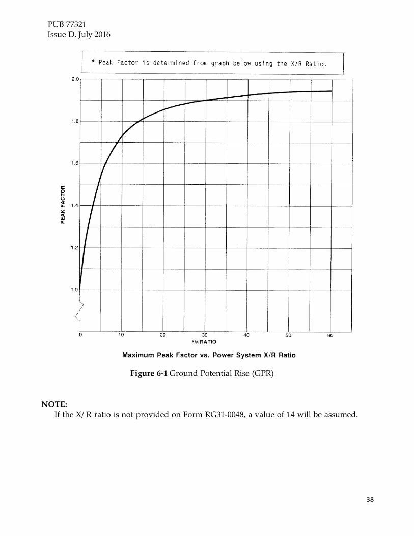
6.4.1 Peak Asymmetrical Voltage Formula
The formula used to determine the peak asymmetrical ground potential rise (GPR) is:
GPR=Ir-f ×Zg ×√2 ×Kp
Where, GPR is Ground Potential Rise Ir-f Zg Kp
is earth return fault current is grid impedance is the peak factor from the table on the next page
PUB 77321 Issue D, July 2016
38
Figure 6-1 Ground Potential Rise (GPR) NOTE:
If the X/ R ratio is not provided on Form RG31-0048, a value of 14 will be assumed.

PUB 77321 Issue D, July 2016
39
6.5 Ground Potential Distribution From the Edge of the High Voltage
Location (substation etc) Ground Grid With Respect to Remote Earth
Graphs depicting the fraction of total ground potential rise (GPR) in relation to the distance from the edge of the grid are provided in Exhibits 6-2, 6-3, 6-4 and 6-5. These graphs will be used by CenturyLink to determine the physical distance from the edge of grid to the 300 volt point if actual test results, using fall of potential,(see IEEE 367 and IEEE 81.2) were not provided. The vertical axes of these graphs represent a fractional ratio of a selected voltage to the GPR. As a ratio the type of voltage (RMS, peak, and peak asymmetrical) selected is of no consequence. CenturyLink uses 300 volts as the selected voltage to determine the minimum distance from the edge of the grid to the general purpose cable splice location. Linear interpolation between graphs may be used to determine distances from the edge of grid areas not given.

PUB 77321 Issue D, July 2016
40
Exhibit 6-2 (GPR) 1600 Square Foot Grid

PUB 77321 Issue D, July 2016
41
Exhibit 6-3 (GPR) 35,000 Square Foot Grid

PUB 77321 Issue D, July 2016
42
Exhibit 6-4 (GPR) 290,000 Square Foot Grid

PUB 77321 Issue D, July 2016
43
Exhibit 6-5 (GPR) 935,000 Square Foot Grid

PUB 77321 Issue D, July 2016
44
7.0 High Dielectric Strength Copper Cable and High Voltage Protection
7.1 CenturyLink Provided High Voltage Protection When CenturyLink provides high voltage protection, the customer requesting service will be required to provide the following:
Mounting structure (plywood back board, H Frame etc) Conduit- 2 to 4 inch Sch40 PVC placed to the public right of way at
least 10 feet beyond the fence surrounding the electrical supply location. Local power from DC batteries or local AC utilizing a UPS or inverter system Local ground source from the station grounding system

PUB 77321 Issue D, July 2016
45
Exhibit 7-1 CenturyLink Provided High Voltage Protection

PUB 77321 Issue D, July 2016
45
7.2 Customer Provided High Voltage Protection
When the customer provides high voltage protection, all high voltage protection equipment must be approved by CenturyLink. CenturyLink will interposition the NCTE, NIU as an extended Demarc on the station side of the customer’s high voltage protection equipment. The customer requesting service will be required to provide the following: • Mounting structure -plywood back board • Conduit- 2 to 4 inch PVC placed to at least 10 feet beyond the fence
surrounding the electrical supply location or to the public right of way in some areas.
• CenturyLink or the customer may provide the lightning arrestor and a high voltage isolation jack panel. The jack panel will be considered the primary Demarc for the high voltage location. Installation of the cable facilities directed to a location beyond the high voltage protection device is the sole responsibility of the customer requesting service. In addition, the extended facility shall meet the requirements outlined in IEEE 487-2007™.
• Local ground source from the station grounding system. • Local power from DC batteries or local AC utilizing a UPS or inverter system

PUB 77321 Issue D, July 2016
46
Exhibit 7-2 Customer Provided High Voltage Protection

PUB 77321 Issue D, July 2016
47
HVP
Zone ofInfluence
RemoteDrainageLocationwithRemoteProtectedTerminal
Stubcable
minimum10 Ftseparationbetweenenclosures
ControlHouse
General Use Cable
High Dielectric Strength Cable
Customer provided conduitextended 10 feet beyond fenceor to the public ROW.
Exhibit 7-3 Service into Electrical Supply Location
PUB 77321 Issue D, July 2016
48
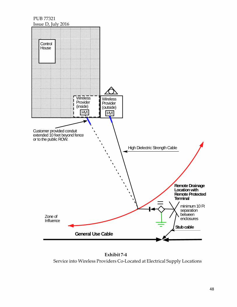
Zone ofInfluence
RemoteDrainageLocationwithRemoteProtectedTerminal
Stubcable
minimum 10 Ftseparationbetweenenclosures
ControlHouse
General Use Cable
High Dielectric Strength Cable
Customer provided conduitextended 10 feet beyond fenceor to the public ROW.
HVI
WirelessProvider(outside)
WirelessProvider(inside)
HVI
Exhibit 7-4 Service into Wireless Providers Co-Located at Electrical Supply Locations

PUB 77321 Issue D, July 2016
49
8.0 Optical Fiber Facilities (see IEEE 1590-2009™)
Fiber optic solutions are used to eliminate the use of dedicated metallic facilities within the ZOI and provide electrical isolation, or when the requested data rate exceeds the ability of copper facilities. A fiber solution is REQUIRED at locations with a calculated peak- asymmetrical GPR value of 17,000 volts (17 kV) or greater or as directed by the CenturyLink Electrical Protection Engineer. There are two types of fiber optic cable solutions available for use in serving electrical supply locations.
• Central office or remote electronic based systems
• Copper-to-fiber hybrid systems. Regardless of the fiber optic solution used, the fiber cable and associated support structures shall be all dielectric (non-metallic).
• All dielectric (no metallic strength members or shield) dedicated fiber optic cable shall be installed within non-metallic conduit/inner duct.
• Electronic Marker Systems (EMS) locating devices shall be placed every 25 feet along the path of the dedicated dielectric fiber cable serving the high voltage supply location.
• Non-metallic cable route markers are to be located a maximum of 500 feet or line of sight the length of the dedicate cable route.
• No “pest” duct (rodent proof with metallic components) or metallic locate wires may be used as they create a serious safety hazard during a GPR event.

PUB 77321 Issue D, July 2016
50
Exhibit 8-1
Customer Provided Hybrid Fiber System

PUB 77321 Issue D, July 2016
51
8.1 CenturyLink Provided Optical Fiber System When CenturyLink provides the optical fiber systems, the Demarc will be located at the remote terminal equipment serving the customers location.
8.1.1 Central Office or Remote Electronic Cabinet Based System Central office based termination equipment, located at/in the electrical supply location, shall have all metallic components bonded together and bonded to the station grounding system. This will ensure the safety of technicians working on the equipment and help prevent damage to the equipment during a GPR event.
8.1.1.1 Equipment Powering Central office or remote electronic based fiber termination equipment, located at/in the electrical supply location, must be locally powered from the electrical supply location batteries or from a customer provided AC power source utilizing a UPS or inverter.
8.1.2 Copper to Fiber Hybrid Hybrid fiber optic systems are specialized electronics that convert electrical signals from the existing copper facilities to optical signals, providing service to the customer location. The electronic components of a hybrid system are:
• Intermediate Electronics – This unit is located at the copper- to-fiber junction (CFJ)
• Optical Equipment Interface (OEI) – This unit is located at the customer location to convert the optical signal back to an electrical signal
An all dielectric non metallic dedicated fiber optic cable is to be installed between the intermediate electronics (CFJ) and the OEI. No locate wires shall be used in placing optical fiber facilities. EMS marker devices should be placed along the trench at regular intervals. Copper to fiber remote termination equipment (OEI), located at/in the electrical supply location, shall be locally powered from the electrical supply location batteries or from a customer provided AC power source utilizing a UPS or inverter.

PUB 77321 Issue D, July 2016
52
8.2 Customer Provided Optical Fiber System
Any Optical fiber system provided by the customer requesting service must follow ANSI/ IEEE STD 1590™ "IEEE Recommended Practice for the Protection of Communication Facilities Serving Electric Supply Locations Using Optical Fiber Systems"© and be approved by CenturyLink. On any customer provided optical fiber systems, the fiber distribution panel or the copper to fiber junction shall be considered the Demarc.
8.2.1 Point to Point or Optical Fiber Handoff When the customer provides their own optical fiber termination equipment (MUX), CenturyLink will hand off service in an approved fiber distribution panel (FDP). The location of this panel may be negotiated with the customer requesting service. Options for placing the FDP include but are not limited to:
• Wall mounted inside the customers building/ cabinet • Rack mounted inside the customers building/ cabinet • In a CenturyLink approved outdoor rated enclosure in the
public right of way.
8.2.2 Customer Provided Hybrid Optical Fiber Solution
Hybrid fiber optic solutions utilizing a copper-to-fiber junction (CFJ) shall have the intermediate electronics placed at or beyond the 300 volt point of the ZOI.
• Fiber equipment located at the CFJ may be line powered, when available, from the CenturyLink circuits or externally powered by an AC source OTHER than from the electrical supply location being served. This is to ensure the safety of CenturyLink technicians working on the equipment and the reliability (survivability) of the protection system.
• For any fiber optic solution used to provide service to a wireless provider at or near substations or on high voltage transmission poles/towers, the CenturyLink Electrical Protection Engineer will require electrical data which shall be requested from the customer/power provider using form RG31- 0048 and the GPR/ZOI shall be calculated by a CenturyLink Electrical Protection Engineer PRIOR to the system being designed

PUB 77321 Issue D, July 2016
53
NOTE: Examples of typical Hybrid Optical Fiber Systems and CFJ Layouts are found in the following diagrams:
Exhibit 8-2 Basic Customer Provided Hybrid Optical Fiber System Layout

PUB 77321 Issue D, July 2016
54
Exhibit 8-3 Example of a Customer Owned Hybrid Optical Fiber System CFJ

PUB 77321 Issue D, July 2016
55
9.0 Acronyms
• GPR Ground Potential Rise • ZOI Zoe of Influence • AC Alternating Current • DC Direct Current • IEEE Institute of Electrical and Electronic Engineers • USOC Universal Service Order Code • Inter-LATA Inter-Local Access and Transport Area • Intra-LATA Intra-Local Access and Transport Area • ISDN Integrated Services Digital Network • CFJ Copper to Fiber Junction • OEI Optical Equipment Interface • FDP Fiber Distribution Panel
10.0 References 10.1 IEEE ANSI/ IEEE STD 487™ "IEEE Guide for the Electrical
Protection of Communication Facilities Serving Electric Power Stations"©
ANSI/ IEEE STD 1590™ "IEEE Recommended Practice for the Protection of Communication Facilities Serving Electric Supply Locations Using Optical Fiber Systems"©
ANSI/ IEEE 789™ “IEEE Standard Performance
Requirements for Communications and Control Cables for Application in High Voltage Environments”©

PUB 77321 Issue D, July 2016
56
10.1 Exhibits
4-1 Design Information for Power Industry Channels
4-2 Intralata Service Offerings Matrix
4-3 Inter-lata Service Offerings Matrix
4-4 through 4-19 Detailed Service Descriptions
5-1 RG31-0048 form and instructions
6-1 Ground Potential Rise (GPR) X/R Chart
6-2 Chart used to help determine the ZOI (1600 square foot grid) 6-
3 Chart used to help determine the ZOI (35000 square foot grid)
6-4 Chart used to help determine the ZOI (290,000 square foot grid) 6-
5 Chart used to help determine the ZOI (935,000 square foot grid)
7-1 CenturyLink Provided High Voltage Protection
7-2 Customer Provided High Voltage Protection
7-3 Service into Electrical Supply Location
7-4 Service into Wireless Providers Co-Located at Electrical Supply
Locations
8-1 Hybrid fiber system zone of influence layout
8-2 Basic Customer Provided Hybrid Optical Fiber System Layout
8-3 Example of a Customer Owned Hybrid Optical Fiber System CFJ