SPECIAL FUNCTION INDICATOR GAGES Contentsjwdonchin.com/Starrett/Catalog/pdf/203.pdf · J.W. DONCHIN...
25
J.W. DONCHIN CO. 4841-43 W. Chicago Ave. • Chicago, IL 60651-3224 Ph: 773-261-2182 • Fax: 773-261-2867 • [email protected] • www.jwdonchin,com SPECIAL FUNCTION INDICATOR GAGES Contents Pg Description Series Range 203 Special Function Dial Gages Chamfer Gages For Internal Chamfers 683 Series 0-90º Chamfer Gages For Internal Chamfers 684 Series 90-127º Chamfer Gages For External Chamfers 685 Series 0-90º Chamfer Gages For External Chamfers 686 Series 90-127º 204 Chamfer Gages (continued) 205 Countersink Gages 687 Series 82º Countersink Gages 688 Series 90º Countersink Gages 689 Series 100º 206 Hole Gages 690 Series .010-.330 Hole Gages 690M Series 0.25-8.35mm 207 Thickness Gages Dial Sheet Gages 170 .150 Dial Sheet Gages 170M 2.5mm 207 Dial Indicator Pocket Gages 1010 Series .375 Dial Indicator Pocket Gages 1010M 9mm 208 Portable Dial Thickness Gages 1015 Series 0-1 Portable Dial Thickness Gages 1015M Series 0-25mm 209 Dial Indicator Snap Gages 1150 Series 0-8 210 Dial Indicator Groove Gages 1175 .375-6 Dial Indicator Groove Gages 1175M 9.5-150mm 211 Dial Caliper Gages 1017 Series Outside Dial Caliper Gages 1018 Series Inside 211 Internal Dial Caliper Gages 1019 .400-1.4 Internal Dial Caliper Gages 1019M 10-35mm 212 Dial Out-Of-Roundness Gages 681 1 1/4-5 Dial Out-Of-Roundness Gages 681M 30-125mm 212 Inside Dial Gages 697 2 3/8-18 Inside Dial Gages 697M 61-458mm 213 Shaft Alignment Clamp Sets 668 Series 214 Crankshaft Distortion Dial/Strain Gage 696 2 3/8-18 Crankshaft Distortion Dial/Strain Gage 696M 61-458mm 215 Crankshaft Distortion Dial/Strain Gage 696 Continued next page.
Transcript of SPECIAL FUNCTION INDICATOR GAGES Contentsjwdonchin.com/Starrett/Catalog/pdf/203.pdf · J.W. DONCHIN...

J.W. DONCHIN CO. 4841-43 W. Chicago Ave. • Chicago, IL 60651-3224Ph: 773-261-2182 • Fax: 773-261-2867 • [email protected] • www.jwdonchin,com
SPECIAL FUNCTION INDICATOR GAGESContents
Pg Description Series Range
203 Special Function Dial Gages
Chamfer Gages For Internal Chamfers 683 Series 0-90º
Chamfer Gages For Internal Chamfers 684 Series 90-127º
Chamfer Gages For External Chamfers 685 Series 0-90º
Chamfer Gages For External Chamfers 686 Series 90-127º
204 Chamfer Gages (continued)
205 Countersink Gages 687 Series 82º
Countersink Gages 688 Series 90º
Countersink Gages 689 Series 100º
206 Hole Gages 690 Series .010-.330
Hole Gages 690M Series 0.25-8.35mm
207 Thickness Gages
Dial Sheet Gages 170 .150
Dial Sheet Gages 170M 2.5mm
207 Dial Indicator Pocket Gages 1010 Series .375
Dial Indicator Pocket Gages 1010M 9mm
208 Portable Dial Thickness Gages 1015 Series 0-1
Portable Dial Thickness Gages 1015M Series 0-25mm
209 Dial Indicator Snap Gages 1150 Series 0-8
210 Dial Indicator Groove Gages 1175 .375-6
Dial Indicator Groove Gages 1175M 9.5-150mm
211 Dial Caliper Gages 1017 Series Outside
Dial Caliper Gages 1018 Series Inside
211 Internal Dial Caliper Gages 1019 .400-1.4
Internal Dial Caliper Gages 1019M 10-35mm
212 Dial Out-Of-Roundness Gages 681 1 1/4-5
Dial Out-Of-Roundness Gages 681M 30-125mm
212 Inside Dial Gages 697 2 3/8-18
Inside Dial Gages 697M 61-458mm
213 Shaft Alignment Clamp Sets 668 Series
214 Crankshaft Distortion Dial/Strain Gage 696 2 3/8-18
Crankshaft Distortion Dial/Strain Gage 696M 61-458mm
215 Crankshaft Distortion Dial/Strain Gage 696
Continued next page.

SPECIAL FUNCTION INDICATOR GAGESContents
Pg Description Series Range
216 Automotive Disc Brake
Indicating Gages 1016 .300-2
Indicating Gages 1016M 8-50mm
217 Cylinder Gages 452 Series 2 1/10-9
Cylinder Gages 452M Series 54-150mm
218 Dial Indicator Diameter Gages 1102 1-12
218 Dial Indicator Diameter Gages 1102M 25-300mm
219 Dial Indicator Diameter Gages Nos. 1102, 1102M Series(continued)
220 Dial Indicator Diameter Gages 1101 Series 12-60
Dial Indicator Diameter Gages 1101M Series 300-1500mm
221 Heavy-Duty Dial Indicator Diameter
Gages 1100 Series 12-60
Gages 1100M Series 300-1500mm
222 Internal-External Adjustable Setting Master for Starrett No. 1102 Diameter GagesCatalog No. 1127 EDP No. 56135
223 Internal-External Adjustable Setting Masters for Starrett Nos. 1100 and 1101 Series DiameterGages No. 1126 Series – Range: 12-60 (300-1500mm)
224 Dial Depth Gages 640 Series 0-1/2
Dial Depth Gages 640M Series 0-10mm
Dial Depth Gages 643 0-.125
Dial Depth Gages 644 0-3
Dial Depth Gages 644M 0-75mm
224 Top Reading Dial Depth Gages 642 Series 0-8.6
Top Reading Dial Depth Gages 642M Series 0-215mm

203
Special Function Dial GagesThis section includes special function dial gages that we list as regular items. Gages are also available with electronic indicators onrequest, where noted.
In addition, we have made many other special function gages to suit a wide variety of our customers’ specific requirements. If you havea special application, we invite you to submit your drawings and specifications to our Special Order Department at 121 Crescent Street,Athol, MA 01331, USA . We will be happy to provide a prompt quotation.
◆ Groove Gages◆ Caliper Gages◆ Depth Gages◆ Out-of-roundness Gages◆ Inside Dial Gages
◆ Automotive Gages◆ Crankshaft Distortion Gages◆ Cylinder Gages◆ Disc Brake Gages◆ Large Diameter Gages
◆ Chamfer Gages◆ Countersink Gages◆ Hole Gages◆ Bore Gages – See Bore Gages Section◆ Direct-Reading Thickness Gages◆ Snap Gages
Chamfer Gages
For Internal Chamfers:No. 683 Series 0-90ºNo. 684 Series 90-127º
For External Chamfers:No. 685 Series 0-90º No. 686 Series 90-127º These gages directly measure the diameter ofchamfered holes. No setting master isnecessary.When the three-blade plunger ispressed against a flat surface, the gage shouldread the set number stamped on the back ofthe indicator. In case of wear, the gage may beadjusted to read the proper number.
All ground surfaces are of hardened tool steel. Indicators are AGD design.
Internal gages will measure the largestdiameter of any chamfer that has anincluded angle within the range of anglesprinted on the dial face of the gage.
External gages will measure the smallestdiameter of any chamfer within the range ofangles printed on the dial face of the gage.
See specifications on next page.
Right: No. 684-2Z ChamferGage with No. F2710-3Electronic Indicator on theNo. 695 Check Stand.
SPECIAL FUNCTIONINDICATOR GAGES
Left, No. 683-1Z;
Right, No. 685-3Z.

204
Inch Reading0-90º Angle 90-127º Angle
Range Catalog No. EDP No. Catalog No. EDP No.
0-3/8� 683-1Z 63684 684-1Z 63688
0-1/2� 683-2Z 63685 684-2Z 63689
0-1� 683-3Z 63686 684-3Z 63690
1-2� 683-4Z 63687 684-4Z 63691
Millimeter Reading with Yellow Dials0-9.5mm 683M-1Z 64989 684M-1Z 64993
0-12.7mm 683M-2Z 64990 684M-2Z 64994
0-25mm 683M-3Z 64991 684M-3Z 64995
25-50mm 683M-4Z 64992 684M-4Z 64996
Inch Reading1/8-1/2� 685-1Z 63692 686-1Z 63695
3/16-1� 685-2Z 63693 686-2Z 63696
1-2� 685-3Z 63694 686-3Z 63697
Millimeter Reading with Yellow Dials3.2-12.7mm 685M-1Z 64997 686M-1Z 65000
4.7-25mm 685M-2Z 64998 686M-2Z 65001
25-50mm 685M-3Z 64999 686M-3Z 65002
No. 683(Internal)
No. 684(Internal)
No. 686(External)
0-90º
0-90º
90-127º
No. 685(External)
Diameter
Diameter Diameter
Diameter
Check Gage Stand for Chamfer, Countersink and Hole GagesDescription Catalog No. EDP No.
8 3/16� H x 6� W x 4� D (212 x 150 x 100mm)Hold Downs – 5� (125mm) on Center – 695 638751/4� (6.3mm) Holes
Chamfer Gages (continued)
Internal Gages
External Gages
NOTE: Also available with electronic indicators.Please specify.
Gages furnished in deluxe padded case.
90-127º
SPECIAL FUNCTIONINDICATOR GAGES

205
Countersink GagesNo. 687 Series 82ºNo. 688 Series 90ºNo. 689 Series 100ºStarrett Countersink Gages are offered inthree different angles so that the gage setson the angular side of the countersink, asopposed to a chamfer gage which sets onthe top edge of the chamfer.
This gage directly reads the large diameter of the countersink in .002� or0.05 mm increments. A set master ring isfurnished with each gage for calibrationand setting. Press the button on top of theindicator to firmly depress the gage headinto the countersink. When the gage isremoved, the indicator reading is held inplace until the reset button is activated.
All ground surfaces are of hardened toolsteel. Indicators are AGD design.
82-90-100º
Diameter
Check Gage Stand for Chamfer, Countersink and Hole GagesDescription Catalog No. EDP No.
8 3/16� H x 6� W x 4� D (212 x 150 x 100mm)Hold Downs – 5� (125mm) on Center – 1/4� (6.3mm) Holes
695 63875
Inch Reading82º Angle 90º Angle 100º Angle
Range Catalog No. EDP No. Catalog No. EDP No. Catalog No. EDP No.
.020-.170� 687-1Z 63698 688-1Z 63702 689-1Z 63706
.160-.360� 687-2Z 63699 688-2Z 63703 689-2Z 63707
.360-.560� 687-3Z 63700 688-3Z 63704 689-3Z 63708
.560-.780� 687-4Z 63701 688-4Z 63705 689-4Z 63709
Millimeter Reading with Yellow Dials0.5-4.3mm 687M-1Z 65003 688M-1Z 65007 689M-1Z 65011
4-9mm 687M-2Z 65004 688M-2Z 65008 689M-2Z 65012
9-14.2mm 687M-3Z 65005 688M-3Z 65009 689M-3Z 65013
14.2-19.8mm 687M-4Z 65006 688M-4Z 65010 689M-4Z 65014
Nos. 687,688, 689
NOTE: Also available with electronic indicators.Please specify.
Gages furnished in deluxe padded case.
Left-to-right: Nos. 687-4Z, No. 688-3Z, No. 689-1Z.
SPECIAL FUNCTIONINDICATOR GAGES

206
Hole GagesNo. 690 Series .010-.330�
No. 690M Series 0.25-8.35mm
These hole gages will check hole diameters to .001� and 0.02mm. They are fast, accurate, easy to read and have a balanced design for easy one-hand operation.
The gage can be pressed down on a flat surface and checked so the size should read the same as the set numberstamped on the back of the indicator. It can also be checked and set with anoptional “setting master”.
All ground surfaces are of hardened toolsteel. Indicators are AGD design.
Holes that need to be accurately checkedmust have no chamfers or countersinks.
Inch Reading Gages Set Masters (Optional)
Range Catalog No. EDP No. Part No. EDP No.
.010-.040� 690-1Z 63710 PT23710-1 63879
.030-.130� 690-2Z 63711 PT23710-2 63880
.130-.230� 690-3Z 63712 PT23710-3 63881
.230-.330� 690-4Z 63713 PT23710-4 63882
Millimeter Reading with Yellow Dials.25-1.00mm 690M-1Z 63714 PT23710-5 63883
.75-3.30mm 690M-2Z 63715 PT23710-6 63884
3.30-5.85mm 690M-3Z 63716 PT23710-7 63885
5.85-8.35mm 690M-4Z 63717 PT23710-8 63886
No. 690
MeasureDiameter
Check Gage Stand for Chamfer, Countersink and Hole GagesDescription Catalog No. EDP No.
8 3/16� H x 6 � W x 4� D (212 x 150 x 100mm)Hold Downs – 5� (125mm) on Center – 695 638751/4� (6.3mm) Holes
NOTE: Also available with electronic indicators.Please specify.
Gages furnished in deluxe padded case.
Left, No. 690-3Z; right, No. 690M-2Z.
SPECIAL FUNCTIONINDICATOR GAGES

207
Inch ReadingRange Graduation Dial Reading Contacts Catalog No. EDP No.
.375�.001� 0-100
Flat1010Z 53114
.0005� 0-50 1010EZ 53115
.275� .001� 0-100 Round 1010RZ 56067
Millimeter Reading9mm 0.01mm 0-100 Flat 1010MZ 53116
Inch ReadingRange Graduation Dial Reading Catalog No. EDP No.
.150� .001� 0-100 170Z 50647
Millimeter Reading2.5mm 0.2mm 0-100 170MZ 66036
Dial Sheet GagesNo. 170 .150�
No. 170M 2.5mm
Measures the thickness of sheet materialslike paper, cardboard, leather, plastics andmetals. Raise the movable contact, insertthe work, remove thumb, and springpressure holds the work parallel with thecontacts. The thickness is registered on thedial. By turning the knurled bezel, the dialmay be moved to bring the hand to zero.The contact edges are radiused to preventthe work from being marred or deflected.The flat contact area measures 5/16�(8mm) in diameter. Black finish.
◆ Throat depth is 1 1/8� (28.5mm)◆ Furnished in deluxe padded case
Dial Indicator Pocket GagesNo. 1010 Series .375�
No. 1010M 9mm
Handy pocket gage is approximately thesize of a thin pocket watch. Ideal forinspectors, purchasing agents andsalespeople to check the size of materialsup to 3/8� or 9mm thick. The gage fitsnaturally into the curve between the thumband index finger. A slight pull on theserrated top plate raises the spindle.
◆ The throat depth ranges from 1/2�(12.7mm) down to 5/16� (8mm)
◆ Models are available with flat orrounded contacts as listed
◆ The diameter of both the flat or roundcontacts are 1/4� (6.3mm)
◆ The gage has a small count hand for recording each revolution of thelarge hand
◆ The case is chrome plated, and the dialis covered with an unbreakable crystal
◆ Furnished in attractive, protective case
No. 170Z.
No. 1010RZ.
Thickness GagesThree handy, specialized, direct-readinggages, as shown on these two pages.
SPECIAL FUNCTIONINDICATOR GAGES

208
Portable Dial Thickness GagesNo. 1015 Series 0-1�
No. 1015M Series 0-25mm
After inserting work between themeasuring contacts, releasing the lever willcause the spindle to contact the work,giving an accurate size reading becausemeasuring pressure is independent of theuser. Indicators have jewel bearings andcontinuous dials. (Models with balanceddials, other graduations and ranges are also available on special order. Electronicindicators can also be furnished.) Throatdepths include 2 1/2�, 4�, and 6�. Thecontact edges are radiused to prevent thework from being marred or deflected. Theflat contact area measures 1/4� (6.3mm) in diameter and is 1/8� (0.125mm) thick.Special contact sizes and shapes areavailable by request.
Inch Reading
Throat Dial Indicator Without Case Case Only
Depth Range Graduation Dial Reading Model No. Catalog No. EDP No. Catalog No. EDP No.
2 1/2�1/2� .0005� 0-50 1015A-431J 1015A 53119 1015AZZ 55407
1� .001� 0-100 1015B-441J 1015B 53121 1015BZZ 55408
4�1/2� .0005� 0-50 1015A-431J 1015A-4 67646
1� .001� 0-100 1015B-441J 1015B-4 67649
6�1/2� .0005� 0-50 1015A-431J 1015A-6 67652
1� .001� 0-100 1015B-441J 1015B-6 67655
Millimeter Reading
63mm10mm 1015MA-481J 1015MA 56131 1015AZZ 55407
25mm 1015MB-881J 1015MB 56133 1015BZZ 55408
100mm10mm 1015MA-481J 1015MA-100 67647
25mm0.01mm 0-100
1015MB-881J 1015MB-100 67650
150mm10mm 1015MA-481J 1015MA-150 67653
25mm 1015MB-881J 1015MB-150 67656
No. 1015A.
No. 1015A-6.
Packed one in a box.
SPECIAL FUNCTIONINDICATOR GAGES
209
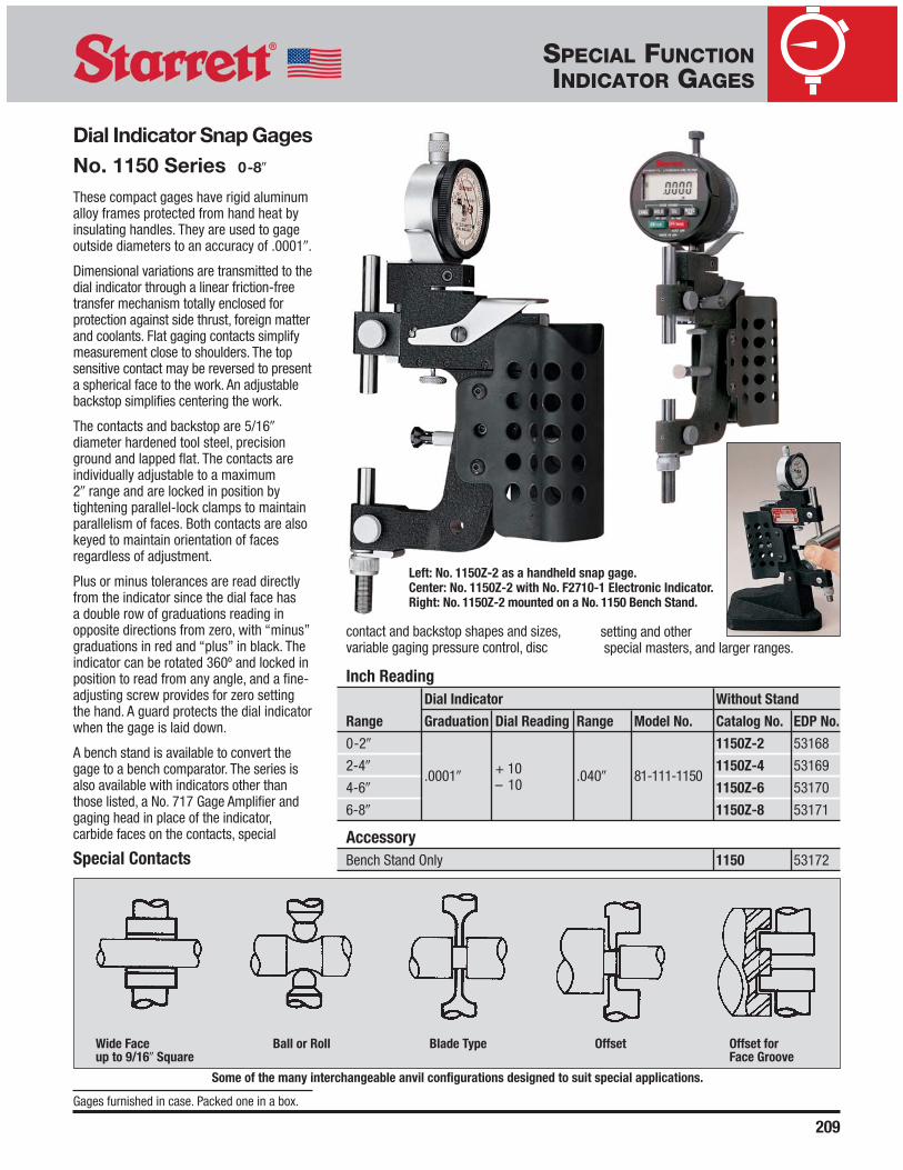
Dial Indicator Snap GagesNo. 1150 Series 0-8�
These compact gages have rigid aluminumalloy frames protected from hand heat byinsulating handles. They are used to gageoutside diameters to an accuracy of .0001�.
Dimensional variations are transmitted to thedial indicator through a linear friction-freetransfer mechanism totally enclosed forprotection against side thrust, foreign matterand coolants. Flat gaging contacts simplifymeasurement close to shoulders. The topsensitive contact may be reversed to presenta spherical face to the work. An adjustablebackstop simplifies centering the work.
The contacts and backstop are 5/16�diameter hardened tool steel, precisionground and lapped flat. The contacts areindividually adjustable to a maximum 2� range and are locked in position bytightening parallel-lock clamps to maintainparallelism of faces. Both contacts are alsokeyed to maintain orientation of facesregardless of adjustment.
Plus or minus tolerances are read directlyfrom the indicator since the dial face has a double row of graduations reading inopposite directions from zero, with “minus”graduations in red and “plus” in black. Theindicator can be rotated 360º and locked inposition to read from any angle, and a fine-adjusting screw provides for zero settingthe hand. A guard protects the dial indicatorwhen the gage is laid down.
A bench stand is available to convert thegage to a bench comparator. The series isalso available with indicators other thanthose listed, a No. 717 Gage Amplifier andgaging head in place of the indicator,carbide faces on the contacts, special
SPECIAL FUNCTIONINDICATOR GAGES
Left: No. 1150Z-2 as a handheld snap gage.Center: No. 1150Z-2 with No. F2710-1 Electronic Indicator.Right: No. 1150Z-2 mounted on a No. 1150 Bench Stand.
Inch ReadingDial Indicator Without Stand
Range Graduation Dial Reading Range Model No. Catalog No. EDP No.
0-2� 1150Z-2 53168
2-4�.0001�
+ 10 .040� 81-111-11501150Z-4 53169
4-6� – 10 1150Z-6 53170
6-8� 1150Z-8 53171
AccessoryBench Stand Only 1150 53172
Wide Face Ball or Roll Blade Type Offset Offset for up to 9/16� Square Face Groove
Some of the many interchangeable anvil configurations designed to suit special applications.
Special Contacts
Gages furnished in case. Packed one in a box.
contact and backstop shapes and sizes,variable gaging pressure control, disc
setting and otherspecial masters, and larger ranges.

Dial Indicator GrooveGagesNo. 1175 .375-6�
No. 1175M 9.5-150mm
This lightweight gage is used for in-processor bench inspection of oil grooves, snapring retainer grooves, “O” ring seat retainergrooves and similar internal recesses. It isalso useful for checking bore dimensionsand testing for taper, bell-mouth and out-of-roundness.
The movable, sensitive gaging contact hasa 1/2� (12.7mm) retractable range andtransfers the measurement through alinear, friction-free transfer mechanism tothe dial indicator. The lower reference jawis fixed and supports the entire weight ofthe gage and the operator’s hands, thuspreventing incorrect gaging pressure andfalse readings.
The reference jaw can be mounted in twopositions on the range adjusting bar. Thebar itself is also adjustable for greater orlesser range. A fine adjustment screw and alock are also provided.
This gage has the following features:◆ Supplied with two sets of jaws, both
readily interchangeable◆ Three sets of contacts are furnished
(Styles 1-10, 2-10, 2-20) that can beattached to the ends of the jaws withoutreplacing the entire jaw. Contacts haveflush ends so that grooves at the bottomof blind holes can be gaged. Thecontacts are hardened steel with a hardchrome finish for long life
◆ Gage can be set with gage blocks orother methods such as micrometers,vernier calipers and ring gages.
Special jaws for 4� and 6� (100mm and150mm) gaging depths, a diameter rangeextension bar from 6-12� (150-300mm),dial indicators graduated in .001�, or anyspecial modification of gaging contacts andjaws, are also available by request throughour Special Order Department
SPECIAL FUNCTIONINDICATOR GAGES
Furnished with storage case. Packed onein a box.
210
No. 1175Z.
1.25� (32)MAX. GAGING DEPTH
2.50� (64)MAX. GAGING DEPTH
3.00� (76.2)GROOVE I.D.
MAX.GROOVE I.D.
LOWER JAW
PT30913
WILLENTERMIN.BORE
CONTACTMOUNTING SCREWPT03497
UPPERJAWPT30916 B
A
LOWER JAWPT30914
CONTACTMOUNTING SCREW08272-0
WILLENTER.375�(9.5)MIN.BORE
Will Enter Maximum
Contact Part No. Minimum Bore Groove I.D. A B
Set Upper Lower Inch mm Inch mm Inch mm Inch mm
Style 1-10 PT30917 PT30917 .375� 9.5 3.00� 75 .100� 2.5 .024� 0.6
Style 2-10 PT30918 PT30919 .690� 17.5 5.00� 125 .140� 3.6 .034� 0.8
Style 2-20 PT30920 PT30921 1.00� 25 6.00� 150 .265� 6.7 .051� 1.3
Dial Indicator
Range Model No. Graduation Reading Range Catalog No. EDP No.
.375-6� 81-136-1175 .0005� ±30 .060� 1175Z 53173
9.5-150mm 81-181-1175 0.01mm ±100 2.5mm 1175MZ 65032
UPPER JAWPT30915
.024�.100�(2.54)
STYLE 1-10 STYLES 2-10, 2-20
Contact Set Specifications:Style 1-10 is for the smaller jaws and can enter a .375� (9.5mm) bore. Styles 2-10 and 2-20 are used on the larger jaws to get the range up to 6� (150mm).
211
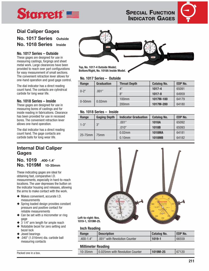
Internal Dial CaliperGagesNo. 1019 .400-1.4�
No. 1019M 10-35mm
These indicating gages are ideal forobtaining fast, comparative I.D.measurements, especially in hard-to-reachlocations. The user depresses the button onthe indicator housing and releases, allowingthe arms to make contact with the work.
◆ Makes convenient, accurate I.D.measurements
◆ Spring loaded design provides constantpressure and positive contact forreliable measurements
◆ Can be set with a micrometer or ringgage
◆ 3 1/4� arm length for ample reach◆ Rotatable bezel for zero setting and
bezel lock◆ Jewel bearings◆ .040� (1.016mm) dia. carbide ball
measuring contacts
Packed one in a box.
Inch ReadingRange Description Catalog No. EDP No.
.400-1.4� .001� with Revolution Counter 1019-1 66559
Millimeter Reading10-35mm 0.025mm with Revolution Counter 1019M-25 67120
Left-to-right: Nos.1019-1, 1019M-25.
SPECIAL FUNCTIONINDICATOR GAGES
Dial Caliper GagesNo. 1017 Series Outside
No. 1018 Series Inside
No. 1017 Series – OutsideThese gages are designed for use inmeasuring castings, forgings and sheetmetal work. Large clearances have beenprovided to reach over part configurationsfor easy measurement of small sections.The convenient retraction lever allows forone-hand operation and good gage control.
The dial indicator has a direct readingcount hand. The contacts are cylindricalcarbide for long wear life.
No. 1018 Series – InsideThese gages are designed for use inmeasuring bores of castings and for inside reading in fabrications. Clearancehas been provided for use in recessedbores. The convenient retraction leverallows one-hand operation.
The dial indicator has a direct readingcount hand. The gage contacts are carbide balls for long wear life.
No. 1017 Series – OutsideRange Graduation Throat Depth Catalog No. EDP No.
0-2� .001�4� 1017-4 65091
8� 1017-8 64959
0-50mm 0.02mm100mm 1017M-100 64179
200mm 1017M-200 64180
No. 1018 Series – InsideRange Gaging Depth Indicator Graduation Catalog No. EDP No.
1-3� 3�.001� 1018A 65092
.010� 1018B 65093
25-75mm 75mm0.02mm 1018MA 64181
0.10mm 1018MB 64182
Top, No. 1017-4 Outside Model;Bottom/Right, No. 1018A Inside Model.

212
Dial Out-Of-RoundnessGagesNo. 681 1 1/4-5�
No. 681M 30-125mm
A compact, easy-to-apply gage forchecking the out-of-roundness ofconnecting rod bearings and holes ofshallow depth. Also for inspectingparallelism and for alignment of slots and assembled parts in jig and fixture work. A dial indicator is mounted on top of the base, and on the bottom a positiveadjustable slide which is readily set to theapproximate hole size or slot width. Thisslide holds the stationary contact plus twocentralizing contacts under spring tension,insuring constant alignment. Bearingsurfaces and contact points are ofhardened steel. The contact points areinserted to a depth of approximately 3/8� (9.5mm).
Dial Indicator
Range Graduation Dial Reading Range Model No. Catalog No. EDP No.
1 1/4-5� .001� 0-25-0 .125� 81-145 681 52899
30-125mm 0.01mm 0-50-0 2.5mm 81-181 681M 52900
Packed one in a box.
SPECIAL FUNCTIONINDICATOR GAGES
Inside Dial GagesNo. 697 2 3/8-18�
No. 697M 61-458mm
These gages are used between two wallsto check parallelism and also to takecomparative measurements of internaldiameters. There are ten rods and oneextension furnished. The rods are markedto designate the approximate overall lengthof the gage. All measuring contacts arerounded. Tool can be set with a micrometer.
The indicator bezel is rotated to adjust thedial in relation to the hand and has a non-breakable crystal. The movement of the dialindicator is approximately 5/32� (4mm).Rods of different lengths can also befurnished on request.
Furnished in attractive, protective case. Packedone in a box.
Range Graduation Dial Reading One Revolution Catalog No. EDP No.
2 3/8-18� .001� 0-20-0 .040� 697Z 52907
61-458mm 0.02mm 0-50-0 1.0mm 697MZ 52908

213
Shaft Alignment ClampSetsNo. 668 SeriesThe Starrett Shaft Alignment Clamp isdesigned for fast, precise alignment ofmotors, pumps, compressors, etc. Thissystem is capable of addressing radial andangular misalignment problems and can beset up within minutes.
Features◆ Lightweight clamp design made of black
anodized aluminum◆ Rigid 3/8� diameter stainless steel
indicator posts provided in three lengths(5�, 7 7/16�, and 9�)
◆ Extension plate allows for added radialclearance
◆ Heavy-duty roller chain can accommodateup to a 7 1/2� diameter shaft
◆ Sets are available with either two StarrettNos. 196B5 or 81-141J Indicators
◆ Excess roller chain can be secured to theside of the chain clamp
◆ A second shaft alignment clamp can bemounted across from the first clamp to actas a vertical “target” for face alignment
Description Catalog No. EDP No.
1 each: Chain Clamp, Extension Plate, Posts (5�, 7 7/16�, 9�), S668A 67150without Case
2 each: Chain Clamp, Extension Plate, Posts (5�, 7 7/16�, 9�), S668BZ 67151with Fitted Case
2 each: Chain Clamp, No. 196B5 Indicator, PT18724 Snug, S668CZ 67152Extension Plate, Posts (5�, 7 7/16�, 9�), with Fitted Case
2 each: Chain Clamp, No. 81-141J Indicator,No. 657Y Indicator Attachment, No. PT18724 Snug, S668DZ 67153Extension Plate, Posts (5�, 7 7/16�, 9�), with Fitted Case
Photo Individual Catalog EDPKey Components No. No.
AChain Clamp
668 67155Only
BExtension Plate
PT99529 67454Screw, Washer
C 5� Post PT27981 67302
D 7 7/16� Post 657G 52753
E 9� Post PT27982 67303
F Snug Complete PT18724 50710
GIndicator
657Y 52765Attachment
No. S668CZ mounted on coupling.
No. S668DZ.
A
C
D
E
G
B
F
SPECIAL FUNCTIONINDICATOR GAGES

214
SPECIAL FUNCTIONINDICATOR GAGES
No. 696B Balancing Attachment isfurnished with the gage. For certainapplications, like turning the crank undertest with the gage in place, the attachmentcan be adjusted to maintain the face of theindicator upward or in desired position. Toinstall it on a strain gage in use, remove theknurled clamping nut, then the doweledplate or end strap at either end by thescrew. The unit is then positioned over thehubs on two sides of the indicator head. Aspring plunger provides the friction thatholds the balance in proper relation toposition. The parts are nickel plated.
The dial indicator movement isapproximately 5/32� (4mm) and with rodsand extension, provides a range from 2 3/8-18� or 61-458mm. There are 10 rods and one extension furnished. Therods are marked to designate theapproximate overall length of the gage.The indicator has a movable bezel to adjust the dial in relation to the hand and a non-breakable crystal.
This gage was designed in collaborationwith the Hartford Steam Boiler Inspectionand Insurance Company. It was known asthe Hartford Steam Boiler Engine StrainGage and is used by their inspectors tocheck the distortion of engine shafts andframes as shown.
Crankshaft DistortionDial/Strain GageNo. 696 2 3/8-18�
No. 696M 61-458mm
An ideal gage for checking bearingalignment or shaft deflection withoutdismantling the engine. Also useful as astrain gage on engine frames. This insidemeasuring gage checks the distortion ofcrankshaft webs (Fig. 1 and Fig. 2 nextpage). This distortion bears a direct relationto existing misalignment or excessivebearing wear. The gage makes it possibleto check bearing alignment or undue shaftdeflection without dismantling the engine.Used on all diesel engine shafts and thecenter crankshafts on any type of engine orcompressor, the gage can also be appliedas a strain gage on engine frames (Fig .3and Fig. 4 next page) while the engine isoperating. A comparison of readings takenat top and bottom positions indicates anymisalignment of cylinder and frame whichresults in local over-stress and eventualcracking of the frame neck.
With a special spring tension in the dialindicator, the gage is self-sustaining in anyposition without sacrificing necessaryrigidity, thus leaving the operator’s handsfree. The contact points are conical, with anapproximate 60º included angle, hardenedand ground to a sharp point, and will stay inplace on 45º surfaces.
No. 696B Balancing Attachment.
See specifications on next page.

215
SPECIAL FUNCTIONINDICATOR GAGES
STRAIN GAGE
C-CLAMP ON RIB
CRACK FROMUNSYMMETRICAL STRAIN
STRAIN GAGE APPLIED TO ENGINE FRAME (WHILE OPERATING),DIFFERENCE BETWEEN TOP AND BOTTOM READINGS OF THE STRAINGAGE INDICATES IMPROPER ALIGNMENT, CAUSING CRACKS.
CYLINDER
DRAIN PIPE
ENGINEFRAME
MISALIGNMENT OF CYLINDER AND ENGINE FRAME (SHOWNEXAGGERATED FOR PURPOSES OF ILLUSTRATION).
STRAIN GAGE
STRAIN GAGE
OIL PIPE
A
B
DISTORTION OF FLANGEFROM MISALIGNMENT.
TO DETERMINE ALIGNMENT, SET THESTRAIN GAGE SO THAT IT JUST CLEARSCONNECTING ROD.
TURN ENGINE UNTILCONNECTING ROD NEARLYTOUCHES STRAIN GAGE RODON OTHER SIDE AND TAKE AREADING AT EACH QUARTER.
FIG. 1
STRAIN GAGE APPLIED TO CRANK OF DIESELENGINE TO DETERMINE IMPROPER ALIGNMENT.
Dial Indicator
Dial RangeRange Graduation Reading One Rev. Description Catalog No. EDP No.
Strain Gage 2 3/8-18� .001� 0-20-0 .040� with Balancing 696Z 52901
Attachment
Millimeter Strain 61-458mm 0.02mm 0-50-0 1mm Gage with 696MZ 52902
Balancing Attachment
Description Catalog No. EDP No.
Balancing Attachment Only 696B 52903Gage furnished with 10 rods, sharp points and balancing attachment in attractive,protective case.
Crankshaft Distortion Dial/Strain Gage (continued)
No. 696
FIG. 3
FIG. 2
FIG. 4

216
.300-2� rangeCatalog No. EDP No. Graduation Description
1016 63795 .001�Adjustable Dial Indicator and No. 2G Gage Block Standard
8-50mm range
1016M 63796 0.01mmAdjustable Dial Indicator and No. 2MG Gage Block Standard
Automotive Disc BrakeIndicating GagesNo. 1016 .300-2�
No. 1016M 8-50mm
This gage is a companion gage to the No. 458 Series Micrometer. It is an indicatorgage used to measure the thickness of discbrake rotors and to determine the depth ofgrooves worn in the rotor.
This gage consists of a 1� (25mm) range,.001� (0.01mm) indicator reverse loaded,mounted on a frame with a 60° pointedanvil and a flat indicator contact. This gageis adjustable to allow reading dimensionsfrom .300� (8mm) to 2� (50mm) in onegage, eliminating the need for two separategages. The frame has a 3 3/8� (85mm)depth.
Readability Features◆ Clear, easily read large numbers and
sharp graduations on both regular andcounter dials
Ease-of-Handling Features◆ Balanced frame design for comfortable
and accurate measuring◆ Gracefully designed tapered frame for
use in tight places◆ Lightweight◆ Easy plunger action to set the reading◆ Adjustable to read through .300� (8mm)
to 2� (50mm) range
Accuracy and Long-Life Features◆ Stable steel frame◆ Hardened indicator gear action◆ Extremely hard and finely finished
measuring surfaces◆ Furnished with a 1� or 25mm gage
block standard
Measuring the groove depth of a disc brake rotor with the No. 1016.
Packed one per box.
NOTE: Also see No. 458 Disc Brake Micrometer in the Micrometer section.
No. 1016.
SPECIAL FUNCTIONINDICATOR GAGES

217
Inch ReadingRange Graduation Dial Reading One Rev. Catalog No. EDP No.
2 1/2-6� 452B 52339
2 1/2-9�.001� 0-100 .100�
452B-9 52341
2 1/10-6� 452E 52342
2 1/10-9� 452E-9 52344
Millimeter Reading63-150mm
0.02mm 0-100 1.0mm452MB 52340
54-150mm 452ME 52343
AccessoriesExtra Handle for Nos. 452B-9, 452MB PT05805-1/2 72175
Extra Handle for Nos. 452E-9, 452ME PT06722 72275
NOTE: Height from contact points to top of handle is 10� (250mm).
Cylinder GagesNo. 452 Series 2 1/10-9�
No. 452M Series 54-150mm
These convenient, easy-to-use gages areused to determine taper and out-of-roundness of bores, offering a quick andaccurate way to show your customerwhether new rings or reconditioning isnecessary.
The ranges are achieved by the use of twomeasuring contact rods. The gage is easilyand accurately set to a micrometer.
Gages also include the following features:◆ Dial is graduated to show plus or minus ◆ Bezel may be rotated for zero setting◆ Sled is hardened and ground for long,
accurate life and has two long-linecontacts in constant alignment with thecylinder wall. These reference points arespring loaded, making the gage self-centering and non-collapsible
◆ The locking screw (stem protrudingabove the dial) clamps the contactpoints in position for measurement witha micrometer
◆ The handle can be locked in anyperpendicular or angular position andmay also be transformed by a slight turninto a toggle joint with a wide sweep
◆ Extra handles may be ordered to make along extension
Packed one in a box.
No. 452B.
SPECIAL FUNCTIONINDICATOR GAGES

218
SPECIAL FUNCTIONINDICATOR GAGES
Dial Indicator Diameter GagesThese gages measure both outside and inside diameters bycomparing dimensions to gage blocks or an adjustablesetting master. Each gage consists of a strong rectangularbox beam with a sensitive gaging contact at one end and areference gaging contact at the other.
All of the diameter gages have these features:◆ The sensitive contact transfers dimensions to the dial
indicator through a linear friction-free mechanism◆ There are two gage feet at the reference end of the gage
and one foot at the sensitive end of the gage to set thegage on the work and align the contacts
◆ Gage depth is set by adjusting the gage feet up or down◆ A lever-actuated reverse mechanism loads the gage for
either inside or outside diameter measurements
◆ The gage contacts are easily changed to I.D. or O.D.gaging by turning them end for end
◆ Unless otherwise specified, the dial indicator sent withthe gage reads in .0005� increments with a total range of±.030�. The dial has a double row of graduations readingin opposite directions – minus in red and plus in black
◆ On the following pages we list our standard line but tosuit other needs we also can furnish the following:
1. Any length that is required2. Any dial indicator with inch or millimeter reading3. No. 717 Electronic Gage Amplifier and Gaging Head in
place of the indicator4. Electronic indicators can also be furnished on any of
these gages except the No. 11025. Special contact shapes6. Gaging contacts with more depth
A
DE
CC
B
Dial Indicator DiameterGagesNo. 1102 1-12�
No. 1102M 25-300mm
This is a light, easy-to-handle gage that is aworkhorse in its range. Approximate weightis 1 lb., 12 oz. (0.8kg). The gaging depthcan be set within a range of 0-1�(0-25mm) by adjusting the rest foot.Dial indicators are the No. 81-136-623 InchReading (.0005�) or No. 81-181-623Millimeter Reading (0.01mm) models.
The gage should be checked against ourNo. 1127 Master for a precise referencestandard during production gaging. (See thefollowing pages.) Also available on requestwith .0001� or 0.002mm graduations.
See specifications on next page.
Photo Key Description
A Range Lock Screw
B I.D.-O.D. Preload ReversingMechanism Lever
C Rest Foot
D Reference Contact
E Sensitive Contact

219
SPECIAL FUNCTIONINDICATOR GAGES
Sent without case unless otherwise ordered.
Length Range Height Adjustment Catalog No. EDP No.
1-12� 0-1� 1102 56134
1-12" 0-1" 1102-1 69004
25-300mm 0-25mm 1102M 65020
CaseStorage Case to Hold Both Gage and No. 1127 Master 1102ZZ 56136
Dial Indicator Diameter Gages (continued)
Nos. 1102, 1102M Series
REVERSIBLE
REVERSIBLE
NO. 7 SPECIAL FORMCONTACT .062�DIAMETER BALL
STANDARDAGDCONTACT.250�
DIAMETERCARBIDETIPPED BALL
FLANGEGROOVECONTACT.100� MAX.
SPECIAL CONTACTS DESIGNED TO ORDER
.49� RADIUS
.030� RADIUS
STANDARD CONTACTS FURNISHED WITH GAGE
SEE VIEW A
1�MIN. I.D.
LOCK SCREW
INTERNAL-EXTERNAL – FULL ADJ. RANGE 1-12�
GAGINGDEPTH 0-1�;1-2� TOORDERSPACER USED WITH REFERENCE CONTACT
WHEN GAGING WITHOUT REST FEET
ROLL TYPE GAGE REST FEET;ONE FRONT, TWO REAR
.0005 DIAL INDICATOR; OTHERGRADUATIONS CAN BE SUBSTITUTED
NO. 1102
VIEW A
220
SPECIAL FUNCTIONINDICATOR GAGES
A
D E F G H
BC
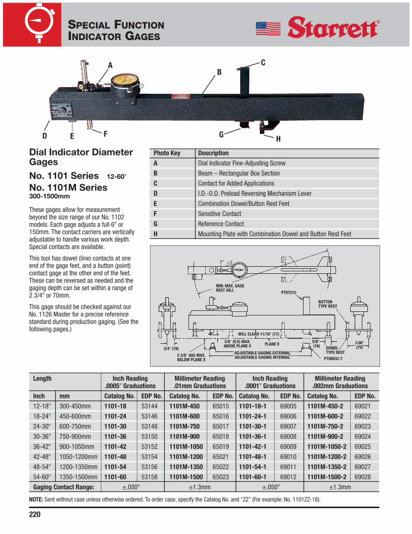
Dial Indicator DiameterGagesNo. 1101 Series 12-60�
No. 1101M Series300-1500mm
These gages allow for measurementbeyond the size range of our No. 1102models. Each gage adjusts a full 6� or 150mm. The contact carriers are verticallyadjustable to handle various work depth.Special contacts are available.
This tool has dowel (line) contacts at oneend of the gage feet, and a button (point)contact gage at the other end of the feet.These can be reversed as needed and thegaging depth can be set within a range of 2 3/4� or 70mm.
This gage should be checked against ourNo. 1126 Master for a precise referencestandard during production gaging. (See thefollowing pages.)
Photo Key Description
A Dial Indicator Fine-Adjusting Screw
B Beam – Rectangular Box Section
C Contact for Added Applications
D I.D.-O.D. Preload Reversing Mechanism Lever
E Combination Dowel/Button Rest Feet
F Sensitive Contact
G Reference Contact
H Mounting Plate with Combination Dowel and Button Rest Feet
5/8�(16)
ADJUSTABLE GAGING EXTERNAL
MIN. MAX. GAGEREST ADJ.
3/4� (19)
2 3/8� (60) MAX.BELOW PLANE X
PT07215
BUTTONTYPE REST
DOWELTYPE REST
3.00�(75)
3/8� (9.5) MAX.ABOVE PLANE X
WILL CLEAR 11/16� (17)
ADJUSTABLE GAGING INTERNAL PT06632-7
PLANE X
Length Inch Reading Millimeter Reading Inch Reading Millimeter Reading.0005� Graduations .01mm Graduations .0001� Graduations .002mm Graduations
Inch mm Catalog No. EDP No. Catalog No. EDP No. Catalog No. EDP No. Catalog No. EDP No.
12-18� 300-450mm 1101-18 53144 1101M-450 65015 1101-18-1 69005 1101M-450-2 69021
18-24� 450-600mm 1101-24 53146 1101M-600 65016 1101-24-1 69006 1101M-600-2 69022
24-30� 600-750mm 1101-30 53148 1101M-750 65017 1101-30-1 69007 1101M-750-2 69023
30-36� 750-900mm 1101-36 53150 1101M-900 65018 1101-36-1 69008 1101M-900-2 69024
36-42� 900-1050mm 1101-42 53152 1101M-1050 65019 1101-42-1 69009 1101M-1050-2 69025
42-48� 1050-1200mm 1101-48 53154 1101M-1200 65021 1101-48-1 69010 1101M-1200-2 69026
48-54� 1200-1350mm 1101-54 53156 1101M-1350 65022 1101-54-1 69011 1101M-1350-2 69027
54-60� 1350-1500mm 1101-60 53158 1101M-1500 65023 1101-60-1 69012 1101M-1500-2 69028
Gaging Contact Range: ±.050� ±1.3mm ±.050� ±1.3mm
NOTE: Sent without case unless otherwise ordered. To order case, specify the Catalog No. and “ZZ” (For example: No. 1101ZZ-18).

221
SPECIAL FUNCTIONINDICATOR GAGES
Heavy-Duty DialIndicator DiameterGagesNo. 1100 Series 12-60�
No. 1100M Series 300-1500mm
These gages combine heavy-dutyconstruction features with adaptability for a wide range of internal and externalmeasurements. The adjustable dowel restlegs ride on slotted mounting plates forhorizontal adjustment. Each of the legs arevertically adjustable to obtain the properrest position on the work and correctalignment on the gaging contacts. 2� or 50 mm range is the vertical adjustment.
The gaging contacts are radiused but maybe modified by request to suit specialgaging conditions.
The indicator and its housing can berotated through to 360º so that theindicator may be read at the mostconvenient angle. The gage should bechecked against our No. 1126 Master for a precise reference standard duringproduction gaging. (See the followingpages.)
A
BC D
E
F G
H
I J
K
Photo Key Description
A I.D.-O.D. Preload Reversing Mechanism Lever
B Tamper Proof Dial Indicator Fine-Adjust Screw
C Beam – Rectangular Box Section
D, E Adjustable Dowel Rest Leg
F, K Dowel Rest
G Sensitive Contact
H Slotted Rest Leg Mounting Plate
I Reference Contact
J Reference Contact Carrier
1 3/16� (30)
ADJUSTABLE GAGING EXTERNAL3.00� (75)
1/8� (3) MAX. BELOWPLANE X
.030R±.001�
2.00 (50) MAX. DROP
1 3/16� (30)
WILL CLEAR 3 1/4� (81)
ADJUSTABLE GAGING INTERNAL
PT30114
PLANE X
5/8�(16)
Length Inch Reading Millimeter Reading Inch Reading Millimeter Reading.0005� Graduations .01mm Graduations .0001� Graduations .002mm Graduations
Inch mm Catalog No. EDP No. Catalog No. EDP No. Catalog No. EDP No. Catalog No. EDP No.
12-18� 300-450mm 1100-18 53128 1100M-450 65024 1100-18-1 69013 1100M-450-2 69029
18-24� 450-600mm 1100-24 53130 1100M-600 65025 1100-24-1 69014 1100M-600-2 69030
24-30� 600-750mm 1100-30 53132 1100M-750 65026 1100-30-1 69015 1100M-750-2 69031
30-36� 750-900mm 1100-36 53134 1100M-900 65027 1100-36-1 69016 1100M-900-2 69032
36-42� 900-1050mm 1100-42 53136 1100M-1050 65028 1100-42-1 69017 1100M-1050-2 69033
42-48� 1050-1200mm 1100-48 53138 1100M-1200 65029 1100-48-1 69013 1100M-1200-2 69034
48-54� 1200-1350mm 1100-54 53140 1100M-1350 65030 1100-54-1 69013 1100M-1350-2 69035
54-60� 1350-1500mm 1100-60 53142 1100M-1500 65031 1100-60-1 69020 1100M-1500-2 69036
Gaging Contact Range: ±.050� ±1.3mm ±.050� ±1.3mm
NOTE: Sent without case unless otherwise ordered. To order case, specify the Catalog No. and “ZZ” (For example: No. 1101ZZ-18).

222
SPECIAL FUNCTIONINDICATOR GAGES
These setting masters are used to check and reset diametergages under production gaging conditions. Each masterconsists of a rigid box beam with reference and sensitiveheads which are individually adjustable along dovetail ways.
A platen on each head locates the diameter gage from itsfeet. The position of the gage contacts is matched by theanvils on the masters which are vertically adjustable. Thereference head anvil has a fine adjustment for final settings,plus a restrictor to help position the gage in the master.
Both heads can be reversed for I.D. or O.D. settings. Eachmaster has a fixed single point rest and two leveling screwswhich provide a three-point suspension. All contact andworking surfaces are hardened and ground.
The setting procedure is as follows: set the diameter gageprecisely to gage blocks or height gages. Then, using thediameter gage, set the master which can then be used as aprecise reference standard for the diameter gage duringproduction gaging.
Setting Masters For Dial Indicator Diameter Gages
A
B C D
E F G
SENSITIVE AND REFERENCE HEADS TOBE REVERSED AS SHOWN IN PHANTOMFOR INTERNAL MEASUREMENT
GAGE RESTPAD SURF.
SET 5.25-12� (133.4-304.8)EXTERNAL MEASUREMENT
SET 1-12� INTERNAL (25.4-304.8)
MEASUREMENT
0-2� ADJ. DROP(50)
0-2� ADJ.DROP
DOVETAIL HARDENED WAYSDOVETAIL LOCKS
Internal-ExternalAdjustable SettingMaster for Starrett No. 1102 Diameter GagesCatalog No. 1127EDP No. 56135This set master is used with our No. 1102Diameter Gages. The internal adjustmentrange is 1-12� (25-300mm) and externaladjustment is 5 1/4-12� (133-300mm).Storage case is available to hold both thegage and master (Catalog No. 1102ZZ,EDP 56136).
PhotoKey Description
A Sensitive Head
B Hardened Rest Platen
C Anvil
D Reference Head
PhotoKey Description
E Fixed Single Point Button Rest
F Beam – Rectangular Box Section
G Leveling Screws (2)

223
SPECIAL FUNCTIONINDICATOR GAGES
A
B C D
EF G
Internal-ExternalAdjustable SettingMasters for StarrettNos. 1100 and 1101Series Diameter GagesNo. 1126 Series 12-60� (300-1500mm)
These set masters are used to check and reset Starrett Nos. 1100 and 1101 Diameter Gages under production gaging conditions.The range is from 12-60� or 300-1500mm.
PLANE X .250� (6.3)ABOVE PLANE X
STRAIGHT-FACEDMASTER ANVIL NIBSSEE DETAIL (1) BELOW
Angular or Conical Nibs and Riser Blocks Quoted Upon Request
DETAIL (1)
ANGULAR OR CONICAL FACE MASTERANVIL NIBS CAN BE FURNISHED ANDARE INTERCHANGEABLE WITH THESTRAIGHT FACED NIBS
DETAIL (2)
RISER BLOCK SETS CAN BEFURNISHED IN INCREMENTS OF2� (50) TO GAGE DEPTH SETTINGRANGE UP TO 6� (150) MAXIMUM
2.00� (50) MAX. BELOW PLANE X. SEE DETAIL (2)
RISERBLOCK
Photo Key Description
A Sensitive Head
B Hardened Rest Platen
C Anvil
D Reference Head
E Leveling Screws (2)
F Beam – Rectangular Box Section
G Fixed Single Point Button Rest
Length Range For Use With Diameter Gage Nos.
Inch mm Inch mm Inch mm Catalog No. EDP No.
12-18� 300-450mm 1100-18 1100M-450 1101-18 1101M-450 1126-18 53160
18-24� 450-600mm 1100-24 1100M-600 1101-24 1101M-600 1126-24 53161
24-30� 600-750mm 1100-30 1100M-750 1101-30 1101M-750 1126-30 53162
30-36� 750-900mm 1100-36 1100M-900 1101-36 1101M-900 1126-36 53163
36-42� 900-1050mm 1100-42 1100M-1050 1101-42 1101M-1050 1126-42 53164
42-48� 1050-1200mm 1100-48 1100M-1200 1101-48 1101M-1200 1126-48 53165
48-54� 1200-1350mm 1100-54 1100M-1350 1101-54 1101M-1350 1126-54 53166
54-60� 1350-1500mm 1100-60 1100M-1500 1101-60 1101M-1500 1126-60 53167
NOTE: Setting masters for larger diameters are also available by request – priced on the application.
Sent without case. Cases are available to hold gage and master. To order case, specify the Catalog No. and “ZZ” (For example: 1126ZZ-18).
224
SPECIAL FUNCTIONINDICATOR GAGES
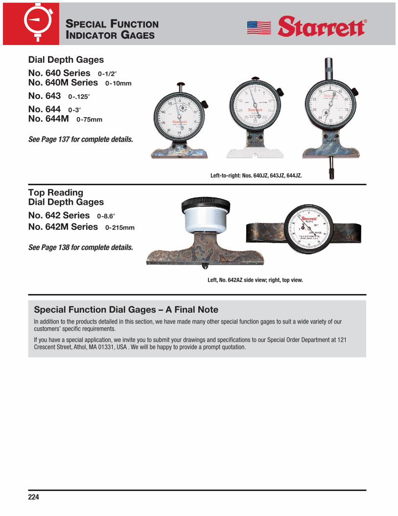
Dial Depth GagesNo. 640 Series 0-1/2�
No. 640M Series 0-10mm
No. 643 0-.125�
No. 644 0-3�
No. 644M 0-75mm
See Page 137 for complete details.
Left-to-right: Nos. 640JZ, 643JZ, 644JZ.
Top Reading Dial Depth GagesNo. 642 Series 0-8.6�
No. 642M Series 0-215mm
See Page 138 for complete details.
Left, No. 642AZ side view; right, top view.
Special Function Dial Gages – A Final NoteIn addition to the products detailed in this section, we have made many other special function gages to suit a wide variety of ourcustomers’ specific requirements.
If you have a special application, we invite you to submit your drawings and specifications to our Special Order Department at 121Crescent Street, Athol, MA 01331, USA . We will be happy to provide a prompt quotation.

J.W. DONCHIN CO.Precision Measuring Equipment and Industrial Supplies since 1924.
www.jwdonchin.com
4841 W. Chicago Ave. - Chicago, IL 60651 • Phone: 773-261-2182 • Fax: 773-261-2867 • [email protected]
J.W. DONCHIN CO.
J.W. Donchin Co. was established in 1924 and has been known world wide ever since. Customer Service is our Main Focus. We offerExpert Product Knowledge, Large Stocking Inventory and Competitive Pricing to assist you in locating and selecting the correcttool or product to fit your needs. (J.W. Donchin Co. is one of L.S. Starrett’s largest stocking distributors.)
Contact Information:
Phone: 773-261-2182
Fax: 773-261-2867
Email: [email protected]
Direct Access Links (View specific information, click on any of the following)
• Latest Website Updates:
• Website:
• Quotes:
• Latest Promos:
• Line Card (Product Lines & Mfg)
Catalog / Promo / Pricelist
• Starrett
• Mitutoyo
• Fowler
• Brown & Sharpe