Specalog for 349F L Hydraulic Excavator …...349F L Hydraulic Excavator 2017 Engine Drive Engine...
15
349F L Hydraulic Excavator 201 7 Engine Drive Engine Model Cat ® C13 ACERT™ Maximum Travel Speed 4.7 km/h 2.9 mph Power – SAE J1349 311 kW 417 hp Maximum Drawbar Pull 335 kN 75,300 lbf Power – ISO 14396 317 kW 425 hp Weights Minimum Weight 48 650 kg 107,200 lb Maximum Weight 51 000 kg 112,400 lb
Transcript of Specalog for 349F L Hydraulic Excavator …...349F L Hydraulic Excavator 2017 Engine Drive Engine...
349F L Hydraulic Excavator 2017
Engine Drive
Engine Model Cat® C13 ACERT™ Maximum Travel Speed 4.7 km/h 2.9 mph
Power – SAE J1349 311 kW 417 hp Maximum Drawbar Pull 335 kN 75,300 lbf
Power – ISO 14396 317 kW 425 hp Weights
Minimum Weight 48 650 kg 107,200 lb
Maximum Weight 51 000 kg 112,400 lb

349F L Hydraulic Excavator Specifications
Engine
Engine Model Cat C13 ACERT
Net Power – SAE J1349 304 kW 408 hp
Power – ISO 14396 317 kW 425 hp
Gross Power – SAE J1995
Bore
Stroke
Displacement
Hydraulic System
Maximum Flow (total)
Main System
322 kW
130 mm
157 mm
12.5 L
770 L/min
432 hp
5.12 in
6.18 in
763 in3
203 gal/min
Swing System 385 L/min 102 gal/min
Pilot System 27 L/min 7.1 gal/min
Maximum Pressure
Main System – Normal 35 000 kPa 5,076 psi
Main System – Heavy Lift 38 000 kPa 5,511 psi
Main System – Travel 35 000 kPa 5,076 psi
Main System – Swing 27 500 kPa 3,989 psi
Pilot System 4120 kPa 598 psi
Boom Cylinder
Bore 170 mm 6.69 in
Stroke 1524 mm 60.00 in
Stick Cylinder
Bore 190 mm 7.48 in
Stroke
TB Family Bucket Cylinder
Bore
Stroke
UB Family Bucket Cylinder
Bore
Stroke
1758 mm
160 mm
1356 mm
170 mm
1396 mm
69.21 in
6.30 in
53.39 in
6.69 in
54.96 in
Drive
Gradeability
Maximum Travel Speed
Maximum Drawbar Pull
30°/70%
4.7 km/h
335 kN
2.9 mph
75,300 lbf
Swing Mechanism
Swing Speed 8.7 rpm
Swing Torque 148.5 kN·m 109,500 lbf-ft
Maximum Swing Torque 221 kN·m 163,000 lbf-ft
Service Refill Capacities
Fuel Tank Capacity 720 L 190 gal
Cooling System 50 L 13.2 gal
Engine Oil (with filter) 38 L 10 gal
Swing Drive (each) 10 L 2.6 gal
Final Drive (each) 15 L 4.0 gal
Hydraulic System (including tank) 570 L 150.6 gal
Hydraulic Tank 407 L 107.5 gal
DEF Tank 41 L 11 gal
Track
Number of Shoes (each side) 52
Number of Track Rollers (each side) 9
Number of Carrier Rollers (each side) 2
Sound Performance
Exterior – ISO 6395 106 dB(A)
Operator – SAE J1166/ISO 6396 69 dB(A)
• When properly installed and maintained, the cab offered by Caterpillar, when tested with doors and windows closed according to ANSI/SAE J1166 OCT98, meets OSHA and MSHA requirements for operator sound exposure limits in effect at time of manufacture.
• Hearing protection may be needed when operating with an open operator station and cab (when not properly maintained or doors/ windows open) for extended periods or in noisy environment.
Standards
Brakes ISO 10265
Cab/FOGS SAE J1356
Cab/ROPS ISO 12117-2
DEF ISO 22241
17

349F L Hydraulic Excavator Specifications
Dimensions All dimensions are approximate.
2
3
1 9
8 7
6
5 4
10
Boom Option Long Reach Reach Mass Boom Boom Boom
7.4 m (24'3") 6.9 m (22'8") 6.55 m (21'6")
Stick Options R4.3TB HD R3.9TB HD R3.35TB HD M3.0UB HD M2.5UB HD (14'1") (12'10") (11'0") (9'10") (8'2")
mm ft/in mm ft/in mm ft/in mm ft/in mm ft/in
1 Shipping Height to Boom – STD/Long FIX Undercarriage 3710 12'2" 3670 12'0" 3730 12'3" 4020 13'2" 4000 13'1"
Shipping Height with Handrail – STD/Long FIX Undercarriage 3370 11'1" 3370 11'1" 3370 11'1" 3370 11'1" 3370 11'1"
2 Shipping Length – STD/Long FIX Undercarriage 12 500 41'0" 11 930 39'2" 11 920 39'1" 11 590 38'0" 11 680 38'4"
3 Tail Swing Radius 3730 12'2" 3730 12'2" 3730 12'2" 3730 12'2" 3730 12'2"
4 Length to Center of Rollers – Long FIX Undercarriage 4360 14'4" 4360 14'4" 4360 14'4" 4360 14'4" 4360 14'4"
5 Track Length – Long FIX Undercarriage 5370 17'7" 5370 17'7" 5370 17'7" 5370 17'7" 5370 17'7"
6 Ground Clearance – Long FIX Undercarriage
Including Shoe Lug Height 480 1'7" 480 1'7" 480 1'7" 480 1'7" 480 1'7"
Not Including Shoe Lug Height 510 1'8" 510 1'8" 510 1'8" 510 1'8" 510 1'8"
7 Track Gauge – Long FIX Undercarriage 2740 9'0" 2740 9'0" 2740 9'0" 2740 9'0" 2740 9'0"
8 Transport Width – STD/Long FIX Undercarriage
600 mm (24") Shoes 3340 10'11" 3340 10'11" 3340 10'11" 3340 10'11" 3340 10'11"
750 mm (30") Shoes 3490 11'5" 3490 11'5" 3490 11'5" 3490 11'5" 3490 11'5"
900 mm (35") Shoes 3640 11'11" 3640 11'11" 3640 11'11" 3640 11'11" 3640 11'11"
9 Cab Height – STD/Long FIX Undercarriage 3230 10'6" 3230 10'6" 3230 10'6" 3230 10'6" 3230 10'6"
Cab Height with Top Guard – STD/Long FIX Undercarriage 3430 11'3" 3430 11'3" 3430 11'3" 3430 11'3" 3430 11'3"
10 Counterweight Clearance* – STD/Long FIX Undercarriage 1280 4'2" 1280 4'2" 1280 4'2" 1280 4'2" 1280 4'2"
Bucket Type GD GD GD HD HD
Bucket Capacity 3.1 m3 3.1 m3 3.1 m3 3.2 m3 3.2 m3
(4.05 yd3) (4.05 yd3) (4.05 yd3) (4.2 yd3) (4.2 yd3)
Bucket Tip Radius 1866 mm 1866 mm 1866 mm 2046 mm 2046 mm (6'1") (6'1") (6'1") (6'9") (6'9")
*Without shoe lug height.
Dimensions may vary depending on bucket selection.
18

349F L Hydraulic Excavator Specifi cations
Working Ranges All dimensions are approximate.
MetersFeet MetersFeet
40 40
11 11 35 35
10 10
30 9 30 9
25 8
25 8
7 7
20 6 20 6 3 3
5 5 15 15
4 4
10 3 10 3 4 4
2 2 5 5 5
1 5 1
0 0 0 0 2
5 1
R4.3TB HD (14'1") 5 1
2 2
R3.9TB HD (12'10") 2
7 M3.0UB HD (9'10")
10 3 1 7 6 R3.35TB HD (11'0")
10 3 1 6 M2.5UB HD (8'2")
4 4 15 15
5 5
20 6 20 6
7 7 25 25
8 8
30 9 30 9 13 12 1011 9 78 0 1123456 Meters 13 12 1011 9 78 0 1123456 Meters
45 40 35 30 25 05101520 Feet 45 40 35 30 25 05101520 Feet
Boom Option Long Reach Boom Reach Boom Mass Boom 7.4 m (24'3") 6.9 m (22'8") 6.55 m (21'6")
Stick Options R4.3TB HD R3.9TB HD R3.35TB HD M3.0UB HD M2.5UB HD (14'1") (12'10") (11'0") (9'10") (8'2")
Long FIX Undercarriage mm ft/in mm ft/in mm ft/in mm ft/in mm ft/in
1 Maximum Digging Depth 8940 29'4" 8210 26'11" 7660 25'2" 7310 24'0" 6810 22'4"
2 Maximum Reach at Ground Level 12 960 42'6" 12 150 39'10" 11 730 38'6" 11 270 37'0" 10 810 35'6"
3 Maximum Cutting Height 11 170 36'8" 10 730 35'2" 10 820 35'6" 10 290 33'9" 10 090 33'1"
4 Maximum Loading Height 7870 25'10" 7420 24'4" 7430 24'5" 6740 22'1" 6550 21'6"
5 Minimum Loading Height 2220 7'3" 2200 7'3" 2750 9'0" 2570 8'5" 3070 10'1"
6 Maximum Depth Cut for 2440 mm (8'0") 8810 28'11" 8080 26'6" 7520 24'8" 7160 23'6" 6640 21'9" Level Bottom
7 Maximum Vertical Wall Digging Depth 6560 21'6" 5960 19'7" 5830 19'2" 4430 14'6" 4000 13'1"
Bucket Type GD GD GD SD SD
Bucket Capacity 3.1 m3 (4.05 yd3) 3.1 m3 (4.05 yd3) 3.1 m3 (4.05 yd3) 3.2 m3 (4.2 yd3) 3.2 m3 (4.2 yd3)
Bucket Tip Radius 1893 mm (6'3") 1893 mm (6'3") 1893 mm (6'3") 2121 mm (7'0") 2121 mm (7'0")
Dimensions may vary depending on bucket selection.
19

349F L Hydraulic Excavator Specifications
Operating Weights and Ground Pressures
900 mm (35") 750 mm (30") 600 mm (24") Triple Grouser Shoes Triple Grouser Shoes Double Grouser Shoes
kg (lb) kPa (psi) kg (lb) kPa (psi) kg (lb) kPa (psi)
Long FIX Undercarriage
Long Reach Boom – 7.4 m (24'3")
R4.3TB HD (14'1") 50 700 (111,800) 59 (8.6) 49 900 (110,000) 69 (10.0) 49 300 (108,700) 86 (12.5)
Reach Boom – 6.9 m (22'8")
R3.9TB HD (12'10") 50 200 (110,700) 58 (8.4) 49 500 (109,100) 69 (10.0) 48 800 (107,600) 85 (12.3)
R3.35TB HD (11'0") 50 000 (110,200) 58 (8.4) 49 300 (108,700) 68 (9.9) 48 600 (107,100) 84 (12.2)
HD Mass Boom – 6.55 m (21'6")
M3.0UB HD (9'10") 51 000 (112,400) 59 (8.6) 50 300 (110,900) 70 (10.2) 49 600 (109,300) 86 (12.5)
M2.5UB HD (8'2") 50 800 (112,000) 59 (8.6) 50 100 (110,500) 70 (10.2) 49 400 (108,900) 86 (12.5)
Major Component Weights
kg lb
Base Machine (with boom cylinder, without counterweight, front linkage and track)
Long FIX Undercarriage 24 800 54,700
Counterweight
9.0 mt (9.9 t) 9000 19,800
Boom (includes lines, pins and stick cylinder)
Long Reach Boom – 7.4 m (24'3") 5190 11,400
Reach Boom – 6.9 m (22'8") 4630 10,200
Mass Boom – 6.55 m (21'6") 4860 10,700
Stick (includes lines, pins, bucket linkage and bucket cylinder)
R4.3TB HD (14'1") 2990 6,600
R3.9TB HD (12'10") 2760 6,100
R3.35TB HD (11'0") 2540 5,600
M3.0UB HD (9'10") 2930 6,500
M2.5UB HD (8'2") 3140 6,900
Track Shoes (per two tracks)
600 mm (24") double grouser 5240 11,600
750 mm (30") triple grouser 5890 13,000
900 mm (35") triple grouser 6640 14,600
Buckets
TB1880GD – 3.10 m3 (4.05 yd3)
UB1850HD – 3.2 m3 (4.2 yd3)
2440
2840
5,400
6,300
All weights are rounded up to nearest 10 kg and lb except for buckets. Kg and lb were rounded up separately so some of the kg and lb do not match.
Base machine includes 75 kg (165 lb) operator weight, 90% fuel weight, and undercarriage with center guard.
20

349F L Hydraulic Excavator Specifications
Bucket and Stick Forces
Boom Option Long Reach Boom Reach Boom Mass Boom 7.4 m (24'3") 6.9 m (22'8") 6.55 m (21'6")
Stick Options R4.3TB HD R3.9TB HD R3.35TB HD M3.0UB HD M2.5UB HD (14'1") (12'10") (11'0") (9'10") (8'2")
kN lbf kN lbf kN lbf kN lbf kN lbf
TB Linkage
General Duty Capacity
Bucket Digging Force (ISO) 267 60,020 268 60,250 268 60,250
Stick Digging Force (ISO) 170 38,220 183 41,140 199 44,740
Bucket Digging Force (SAE) 235 52,830 236 53,050 236 53,050
Stick Digging Force (SAE) 166 37,320 177 39,790 193 43,390
Heavy Duty
Bucket Digging Force (ISO) 266 59,800 268 60,250 268 60,250
Stick Digging Force (ISO) 172 38,670 184 41,360 201 45,190
Bucket Digging Force (SAE) 234 52,610 235 52,830 235 52,830
Stick Digging Force (SAE) 167 37,540 179 40,240 195 43,840
Severe Duty
Bucket Digging Force (ISO) 265 59,570 266 59,800 266 59,800
Stick Digging Force (ISO) 171 38,440 184 41,360 200 44,960
Bucket Digging Force (SAE) 228 51,260 229 51,480 229 51,480
Stick Digging Force (SAE) 166 37,320 178 40,020 193 43,390
Extreme Duty
Bucket Digging Force (ISO) 265 59,570 266 59,800 266 59,800
Stick Digging Force (ISO) 171 38,440 184 41,360 200 44,960
Bucket Digging Force (SAE) 228 51,260 229 51,480 229 51,480
Stick Digging Force (SAE) 166 37,320 178 40,020 193 43,390
UB Linkage
Heavy Duty
Bucket Digging Force (ISO) 296 66,540 296 66,540
Stick Digging Force (ISO) 212 47,660 241 54,180
Bucket Digging Force (SAE) 258 58,000 258 58,000
Stick Digging Force (SAE) 205 46,090 231 51,930
Severe Duty
Bucket Digging Force (ISO) 290 65,190 290 65,190
Stick Digging Force (ISO) 211 47,430 239 53,730
Bucket Digging Force (SAE) 252 56,650 252 56,650
Stick Digging Force (SAE) 203 45,640 229 51,480
21

349F L Hydraulic Excavator Specifications
Long Reach Boom Lift Capacities – Counterweight: 9.0 mt (9.9 t) – Heavy Lift: On
4.3 m (14'1")
LR4.3TB
1500 mm/60 in
9000 mm kg 360 in lb
7500 mm kg 300 in lb
6000 mm kg 240 in lb
4500 mm kg 180 in lb
3000 mm kg 120 in lb
1500 mm kg 60 in lb 0 mm kg
0 in lb –1500 mm kg
–60 in lb –3000 mm kg
–120 in lb –4500 mm kg
–180 in lb –6000 mm kg
–240 in lb
*14 150 *14 150 *31,550 *31,550
7.4 m (24'3")
3000 mm/120 in
*12 200 *27,500 *17 800 *40,050 *24 450 *55,300 *24 950
*12 200 *27,500 *17 800 *40,050 *24 450 *55,300 *24 950
4500 mm/180 in
*23 250 *49,850 *18 950 *44,950 *18 100 *41,800 *21 750 *49,700 *26 000 *56,350 *23 400 *50,500 *19 150 *41,000
21 400 46,250
*18 950 42,450
*18 100 40,750 18 700 40,200 18 750 40,300 19 050 40,950
*19 150 *41,000
6000 mm/240 in
*14 200 *30,600 *16 700 *36,000 *18 800 *40,600 *20 050 *43,400 *20 350 *44,100 *19 750 *42,750 *18 100 *39,100 *15 050 *32,000
900 mm (35") triple grouser shoes
2740 mm (9'0")
7500 mm/300 in
*14 200 *30,600
14 100 30,450 13 150 28,400 12 550 27,050 12 250 26,350 12 150 26,150 12 300 26,450 12 650 27,250
*12 050 *26,150 *13 450 *29,150 *14 750 *31,900
15 550 33,450 15 250 32,800 15 150 32,600
*14 350 *30,850 *11 450
10 800 23,250 10 200 22,000
9650 20,800
9250 19,900
9000 19,350
8900 19,150
8950 19,350
9300
9000 mm/360 in
*9700 *20,800 *10 100 *22,000 *10 750 *23,400 *11 550 *25,100
12 150 26,150 11 850 25,500 11 650 25,100 11 600 25,000
*11 200
8600 18,350
8400 18,000
8100 17,400
7750 16,700
7400 15,950
7150 15,400
7000 15,050
6950 14,950
7050
4360 mm (14'4")
5370 mm (17'7")
10 500 mm/420 in
*7350
*9850 *19,700
9850 21,150
9650 20,700
9450 20,350
9350
mm in
*7150 *7150 *15,800 *15,800
*6900 *6900 *15,250 *15,250
6400 *6900 6300 *15,200 14,000
6250 *7100 5750 13,400 *15,550 12,700
6050 *7400 5400 13,000 *16,250 11,950
5900 *7950 5300 12,600 *17,450 11,600
5700 *8750 5300 12,300 *19,250 11,700
5650 9250 5550 20,350 12,250 10 100 6050 22,300 13,400
*11 200 7050 *24,650 15,650 *11 100 9100 *24,400 20,450
8900 350
9890 390
10 570 420
11 010 440
11 220 450
11 230 450
11 040 440
10 620 420
9960 400
9010 360
7630 300
ISO 10567
*Indicates that the load is limited by hydraulic lifting capacity rather than tipping load. The above loads are in compliance with hydraulic excavator lift capacity standard ISO 10567:2007. They do not exceed 87% of hydraulic lifting capacity or 75% of tipping load. Weight of all lifting accessories must be deducted from the above lifting capacities. Lifting capacities are based on the machine standing on a firm, uniform supporting surface. The use of a work tool attachment point to handle/lift objects, could affect the machine lift performance.
Lift capacity stays with ±5% for all available track shoes.
Always refer to the appropriate Operation and Maintenance Manual for specific product information.
22

349F L Hydraulic Excavator Specifications
Reach Boom Lift Capacities – Counterweight: 9.0 mt (9.9 t) – Heavy Lift: On
3.9 m (12'10")
R3.9TB
1500 mm/60 in
9000 mm kg 360 in lb
7500 mm kg 300 in lb
6000 mm kg 240 in lb
4500 mm kg 180 in lb
3000 mm kg 120 in lb
1500 mm kg 60 in lb 0 mm kg
0 in lb –1500 mm kg
–60 in lb –3000 mm kg
–120 in lb –4500 mm kg
–180 in lb –6000 mm kg
–240 in lb
*38,550 *38,550
6.9 m (22'8")
3000 mm/120 in
*15 300 *34,450 *22 300 *50,350 *30 900 *66,650
*15 300 *34,450 *22 300 *50,350 *30 900 *66,650
4500 mm/180 in
*23 750 *51,000 *25 800 *59,100 *23 800 *55,050 *28 150 *61,050 *26 350 *57,100 *23 050 *49,700 *17 400 *36,750
22 000 47,450 20 450 44,050 19 700 42,450 19 500 41,950 19 600 42,100 19 900 42,850
*17 400 *36,750
900 mm (35") triple grouser shoes
2740 mm (9'0")
6000 mm/240 in
*14 800 *32,050 *17 300 *37,400 *19 450 *42,050 *20 700 *44,850 *20 950 *45,350 *20 050 *43,400 *17 800 *38,300 *13 100 *27,200
ISO 10567
*14 800 *32,050
14 450 31,150 13 600 29,350 13 050 28,150 12 800 27,550 12 750 27,450 12 950 27,850
*13 100 *27,200
7500 mm/300 in
*18,700
*11 650 *25,350 *12 800 *27,750 *14 150 *30,650 *15 400 *33,350
15 900 34,250 15 700 33,750 15 650 33,650
*13 750 *29,250
*18,700
11 350 24,450 10 950 23,550 10 450 22,500
9950 21,450
9600 20,700
9400 20,250
9350 20,150
9500 20,550
4360 mm (14'4")
5370 mm (17'7")
9000 mm/360 in
mm in
7860 310
8970 350
9720 380
10 190 400
10 420 410
10 430 410
10 220 410
9770 390
9050 360
7980 320
6380 250
*11 050 *22,950 *11 550 *25,250 *12 300 *26,750
12 400 26,650 12 150 26,150 12 050 25,900 12 050
*7900 *7900 *17,500 *17,500
*7550 *7550 *16,600 *16,600
8450 *7450 7400 18,100 *16,400 16,350
8200 *7600 6700 17,650 *16,650 14,750
7950 *7900 6300 17,100 *17,400 13,900
7650 *8500 6150 16,500 *18,700 13,550
7450 *9400 6250 16,050 *20,700 13,700
7350 10 750 6600 15,800 23,650 14,500
7350 12 000 7300 26,500 16,200
*12 450 8800 *27,450 19,600 *11 950 *11 950 *26,150 *26,150
*Indicates that the load is limited by hydraulic lifting capacity rather than tipping load. The above loads are in compliance with hydraulic excavator lift capacity standard ISO 10567:2007. They do not exceed 87% of hydraulic lifting capacity or 75% of tipping load. Weight of all lifting accessories must be deducted from the above lifting capacities. Lifting capacities are based on the machine standing on a firm, uniform supporting surface. The use of a work tool attachment point to handle/lift objects, could affect the machine lift performance.
Lift capacity stays with ±5% for all available track shoes.
Always refer to the appropriate Operation and Maintenance Manual for specific product information.
23

349F L Hydraulic Excavator Specifications
Reach Boom Lift Capacities – Counterweight: 9.0 mt (9.9 t) – Heavy Lift: On
3.35 m (11'0") 6.9 m (22'8")
R3.4TB
3000 mm/120 in 4500 mm/180 in
*20 750 *20 750 *44,500 *44,500 *25 750 21 500 *55,300 46,450 *18 600 *18 600 *44,500 43,700 *20 950 19 850 *48,650 42,700
*14 900 *14 900 *27 700 19 800 *33,650 *33,650 *60,150 42,600 *23 850 *23 850 *25 350 20 000 *53,850 *53,850 *55,000 42,950 *27 400 *27 400 *21 400 20 400 *59,150 *59,150 *46,100 43,850
9000 mm kg 360 in lb
7500 mm kg 300 in lb
6000 mm kg 240 in lb
4500 mm kg 180 in lb
3000 mm kg 120 in lb
1500 mm kg 60 in lb 0 mm kg
0 in lb –1500 mm kg
–60 in lb –3000 mm kg
–120 in lb –4500 mm kg
–180 in lb
900 mm (35") triple grouser shoes
2740 mm (9'0")
4360 mm (14'4")
5370 mm (17'7")
6000 mm/240 in 7500 mm/300 in 9000 mm/360 in
*9050 *9050 *20,050 *20,050
*11 950 11 500 *8500 *8500 *26,250 24,650 *18,750 *18,750 *12 500 11 250 *10 750 8350 *8350 7950 *27,300 24,200 *20,250 17,900 *18,350 17,600
*16 000 15 150 *13 600 10 850 *12 250 8200 *8450 7150 *34,600 32,700 *29,550 23,400 *26,700 17,600 *18,550 15,800 *18 400 14 300 *14 850 10 400 12 700 7950 *8800 6750 *39,700 30,850 *32,250 22,400 27,300 17,100 *19,300 14,850 *20 250 13 550 *15 950 10 000 12 450 7700 *9400 6600 *43,800 29,250 *34,600 21,500 26,750 16,600 *20,700 14,550 *21 150 13 150 16 000 9700 12 250 7550 *10 400 6700 *45,800 28,300 34,400 20,850 26,350 16,250 *22,900 14,800 *20 950 12 950 15 850 9550 12 200 7500 11 600 7150 *45,400 27,900 34,050 20,550 26,250 16,150 25,600 15,750 *19 650 13 000 *15 450 9550 *12 800 8050 *42,450 28,000 *33,250 20,650 *28,150 17,850 *16 700 13 250 *12 600 9950 *35,800 28,600 *27,650 22,250
ISO 10567
mm in
7300 290
8480 330
9270 370
9770 390
10 010 400
10 020 400
9800 390
9330 370
8570 340
7430 290
*Indicates that the load is limited by hydraulic lifting capacity rather than tipping load. The above loads are in compliance with hydraulic excavator lift capacity standard ISO 10567:2007. They do not exceed 87% of hydraulic lifting capacity or 75% of tipping load. Weight of all lifting accessories must be deducted from the above lifting capacities. Lifting capacities are based on the machine standing on a firm, uniform supporting surface. The use of a work tool attachment point to handle/lift objects, could affect the machine lift performance.
Lift capacity stays with ±5% for all available track shoes.
Always refer to the appropriate Operation and Maintenance Manual for specific product information.
24
349F L Hydraulic Excavator Specifications
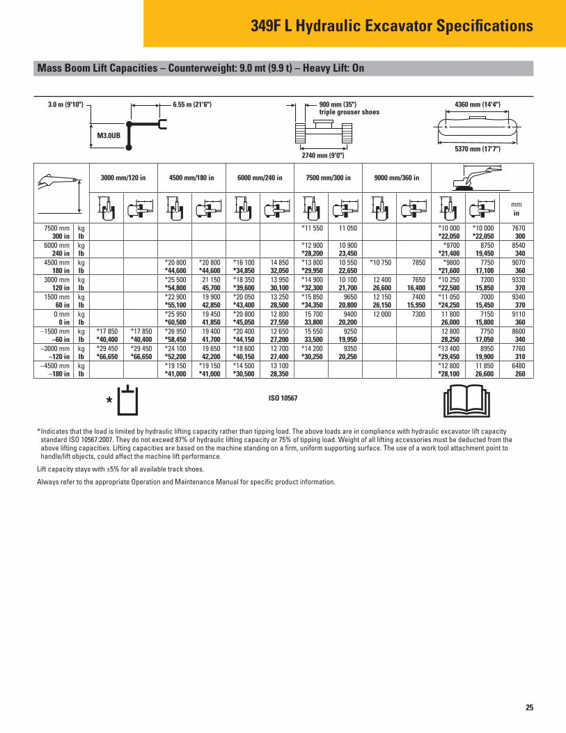
Mass Boom Lift Capacities – Counterweight: 9.0 mt (9.9 t) – Heavy Lift: On
3.0 m (9'10") 6.55 m (21'6")
M3.0UB
3000 mm/120 in 4500 mm/180 in
*20 800 *20 800 *44,600 *44,600 *25 500 21 150 *54,800 45,700 *22 900 19 900 *55,100 42,850 *25 950 19 450 *60,500 41,850
*17 850 *17 850 *26 950 19 400 *40,400 *40,400 *58,450 41,700 *29 450 *29 450 *24 100 19 650 *66,650 *66,650 *52,200 42,200
*19 150 *19 150 *41,000 *41,000
7500 mm kg 300 in lb
6000 mm kg 240 in lb
4500 mm kg 180 in lb
3000 mm kg 120 in lb
1500 mm kg 60 in lb 0 mm kg
0 in lb –1500 mm kg
–60 in lb –3000 mm kg
–120 in lb –4500 mm kg
–180 in lb
900 mm (35") triple grouser shoes
2740 mm (9'0")
4360 mm (14'4")
5370 mm (17'7")
6000 mm/240 in 7500 mm/300 in 9000 mm/360 in
*11 550 11 050 *10 000 *10 000 *22,050 *22,050
*12 900 10 900 *9700 8750 *28,200 23,450 *21,400 19,450
*16 100 14 850 *13 800 10 550 *10 750 7850 *9800 7750 *34,850 32,050 *29,950 22,650 *21,600 17,100 *18 350 13 950 *14 900 10 100 12 400 7650 *10 250 7200 *39,600 30,100 *32,300 21,700 26,600 16,400 *22,500 15,850 *20 050 13 250 *15 850 9650 12 150 7400 *11 050 7000 *43,400 28,500 *34,350 20,800 26,150 15,950 *24,250 15,450 *20 800 12 800 15 700 9400 12 000 7300 11 800 7150 *45,050 27,550 33,800 20,200 26,000 15,800 *20 400 12 650 15 550 9250 12 800 7750 *44,150 27,200 33,500 19,950 28,250 17,050 *18 600 12 700 *14 200 9350 *13 400 8950 *40,150 27,400 *30,250 20,250 *29,450 19,900 *14 500 13 100 *12 800 11 850 *30,500 28,350 *28,100 26,600
ISO 10567
mm in
7670 300
8540 340
9070 360
9330 370
9340 370
9110 360
8600 340
7760 310
6480 260
*Indicates that the load is limited by hydraulic lifting capacity rather than tipping load. The above loads are in compliance with hydraulic excavator lift capacity standard ISO 10567:2007. They do not exceed 87% of hydraulic lifting capacity or 75% of tipping load. Weight of all lifting accessories must be deducted from the above lifting capacities. Lifting capacities are based on the machine standing on a firm, uniform supporting surface. The use of a work tool attachment point to handle/lift objects, could affect the machine lift performance.
Lift capacity stays with ±5% for all available track shoes.
Always refer to the appropriate Operation and Maintenance Manual for specific product information.
25

349F L Hydraulic Excavator Specifications
Mass Boom Lift Capacities – Counterweight: 9.0 mt (9.9 t) – Heavy Lift: On
2.5 m (8'2") 6.55 m (21'6")
M2.5UB
3000 mm/120 in 4500 mm/180 in
*22 650 *22 650 *48,500 *48,500
*58,350 44,750
*23 950 19 650 *56,350 42,200
*18 000 *18 000 *26 050 19 700 *41,100 *41,100 *56,650 42,350 *27 750 *27 750 *22 750 20 000 *60,500 *60,500 *49,200 43,000
*16 800 *16 800 *35,700 *35,700
7500 mm kg 300 in lb
6000 mm kg 240 in lb
4500 mm kg 180 in lb
3000 mm kg 120 in lb
1500 mm kg 60 in lb
0 mm kg 0 in lb
–1500 mm kg –60 in lb
–3000 mm kg –120 in lb
–4500 mm kg –180 in lb
900 mm (35") triple grouser shoes
2740 mm (9'0")
4360 mm (14'4")
5370 mm (17'7")
*13 050 11 950 *28,900 26,950
*15 250 *15 250 *13 800 10 800 *12 700 9650 *33,150 *33,150 *30,200 23,250 *27,950 21,400 *17 150 14 700 *14 500 10 500 *12 850 8450 *37,050 31,700 *31,600 22,600 *28,250 18,650 *19 200 13 850 *15 500 10 100 12 700 7850 *41,500 29,900 *33,650 21,700 27,950 17,250 *20 650 13 250 16 050 9700 12 450 7650 *44,650 28,500 34,550 20,950 27,450 16,800 *21 000 12 900 15 800 9500 12 900 7850 *45,500 27,750 34,000 20,450 28,350 17,250 *20 150 12 800 15 750 9450 14 150 8550 *43,650 27,600 33,900 20,350 *31,150 18,850 *17 800 13 000 *14 000 10 150 *38,300 28,000 *30,800 22,550
*12 750 *12 750 *27,850 *27,850
mm in
7110 280
8030 320
8600 340
8880 350
8890 350
8640 340
8100 320
7210 290
5800 230
ISO 10567
6000 mm/240 in 7500 mm/300 in
*Indicates that the load is limited by hydraulic lifting capacity rather than tipping load. The above loads are in compliance with hydraulic excavator lift capacity standard ISO 10567:2007. They do not exceed 87% of hydraulic lifting capacity or 75% of tipping load. Weight of all lifting accessories must be deducted from the above lifting capacities. Lifting capacities are based on the machine standing on a firm, uniform supporting surface. The use of a work tool attachment point to handle/lift objects, could affect the machine lift performance.
Lift capacity stays with ±5% for all available track shoes.
Always refer to the appropriate Operation and Maintenance Manual for specific product information.
26

349F L Hydraulic Excavator Specifications
Bucket Specifications and Compatibility
349F L 349F L
900 mm (35") Triple Grouser Shoes 600 mm (24") Triple Grouser Shoes
Counterweight – 9.0 mt (9.9 t) Counterweight – 9.0 mt (9.9 t)
Width Capacity Weight Fill ME Boom HD Reach
Boom HD LR Boom ME Boom
HD Reach Boom
mm in m3 yd3 kg lb % M2.5 (8'2")
M3.0 (9'10")
R3.35 HD
(11'0") R3.9 HD (12'10")
LR 4.3 (14'1")
M2.5 (8'2")
M3.0 (9'10")
R3.35 HD
(11'0") R3.9 HD (12'10")Linkage
Without Pin Grabber Coupler
General Duty (GDC)
General Duty XL (GDXL)
Heavy Duty (HD)
Severe Duty (SD)
Extreme Duty (XD)
TB 750 30 0.95 1.24 1311 2,889 100%
TB 900 36 1.23 1.60 1441 3,176 100%
TB 1050 42 1.51 1.98 1525 3,361 100%
TB 1200 48 1.80 2.36 1676 3,694 100%
TB 1350 54 2.10 2.74 1792 3,950 100%
TB 1500 60 2.39 3.13 1943 4,282 100%
TB 1700 68 2.78 3.64 2128 4,690 100%
TB
TB
TB
1850 74 3.08 4.04 2254 4,968 100%
2000 80 3.82 5.00 2457 5,415 100% X
900 36 1.08 1.41 1594 3,513 100%
TB 1050 42 1.34 1.75 1684 3,712 100%
TB 1200 48 1.60 2.09 1834 4,043 100%
TB 1350 54 1.87 2.44 1962 4,324 100%
TB 1500 60 2.14 2.80 2125 4,684 100%
TB 1650 66 2.41 3.15 2286 5,039 100%
TB 1800 72 2.69 3.52 2423 5,340 100%
UB
TB
1850 73 3.19 4.16 2735 6,028 100%
750 30 0.88 1.15 1446 3,187 90%
TB 900 36 1.08 1.41 1677 3,696 90%
TB 1050 42 1.34 1.75 1779 3,921 90%
TB 1200 48 1.60 2.09 1952 4,302 90%
TB 1400 55 1.87 2.44 2180 4,805 90%
TB 1550 61 2.14 2.80 2381 5,248 90%
TB 1700 67 2.41 3.16 2524 5,563 90%
TB 1850 74 2.69 3.52 2726 6,008 90%
UB 1450 58 2.39 3.13 2540 5,598 90%
UB
TB
1850 73 3.21 4.20 2987 6,583 90%
1250 49 1.60 2.09 2224 4,902 90%
TB 1400 55 1.87 2.44 2366 5,215
Maximum load pin-on (payload + bucket)
90%
kg 7876 7133 6868 6342 5282 7643 6914 6663 6147
lb 17,359 15,721 15,137 13,978 11,642 16,845 15,238 14,685 13,548
The above loads are in compliance with hydraulic excavator standard EN474, they do not Maximum Material Density: exceed 87% of hydraulic lifting capacity or 75% of tipping capacity with front linkage fully 2100 kg/m3 (3,500 lb/yd3)extended at ground line with bucket curled.
1800 kg/m3 (3,000 lb/yd3)Capacity based on ISO 7451.
1500 kg/m3 (2,500 lb/yd3)Bucket weight with General Duty tips. 1200 kg/m3 (2,000 lb/yd3)
900 kg/m3 (1,500 lb/yd3)
X Not Recommended
Caterpillar recommends using appropriate work tools to maximize the value customers receive from our products. Use of work tools, including buckets, which are outside of Caterpillar’s recommendations or specifications for weight, dimensions, flows, pressures, etc. may result in less-than-optimal performance, including but not limited to reductions in production, stability, reliability, and component durability. Improper use of a work tool resulting in sweeping, prying, twisting and/or catching of heavy loads will reduce the life of the boom and stick.
27
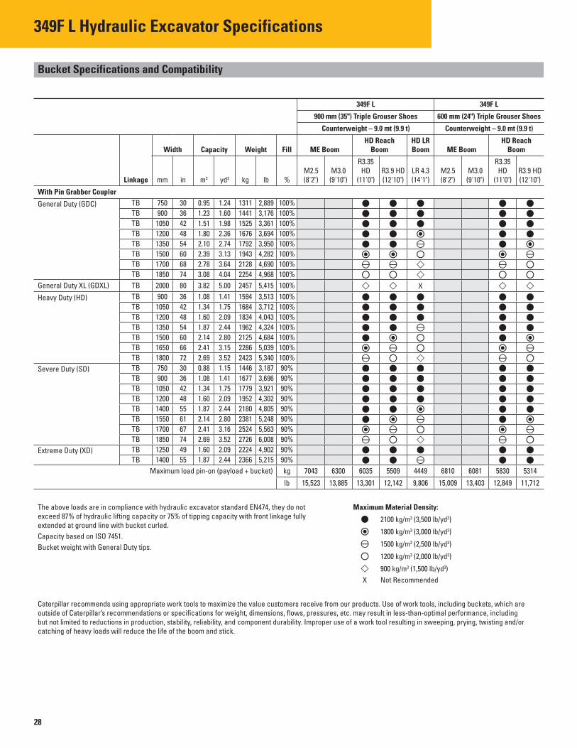
349F L Hydraulic Excavator Specifications
Bucket Specifications and Compatibility
349F L 349F L
900 mm (35") Triple Grouser Shoes 600 mm (24") Triple Grouser Shoes
Counterweight – 9.0 mt (9.9 t) Counterweight – 9.0 mt (9.9 t)
Width Capacity Weight Fill ME Boom HD Reach
Boom HD LR Boom ME Boom
HD Reach Boom
mm in m3 yd3 kg lb % M2.5 (8'2")
M3.0 (9'10")
R3.35 HD
(11'0") R3.9 HD (12'10")
LR 4.3 (14'1")
M2.5 (8'2")
M3.0 (9'10")
R3.35 HD
(11'0") R3.9 HD (12'10")Linkage
With Pin Grabber Coupler
General Duty (GDC)
General Duty XL (GDXL)
Heavy Duty (HD)
Severe Duty (SD)
Extreme Duty (XD)
TB 750 30 0.95 1.24 1311 2,889 100%
TB 900 36 1.23 1.60 1441 3,176 100%
TB 1050 42 1.51 1.98 1525 3,361 100%
TB 1200 48 1.80 2.36 1676 3,694 100%
TB 1350 54 2.10 2.74 1792 3,950 100%
TB 1500 60 2.39 3.13 1943 4,282 100%
TB 1700 68 2.78 3.64 2128 4,690 100%
TB
TB
TB
1850 74 3.08 4.04 2254 4,968 100%
2000 80 3.82 5.00 2457 5,415 100% X
900 36 1.08 1.41 1594 3,513 100%
TB 1050 42 1.34 1.75 1684 3,712 100%
TB 1200 48 1.60 2.09 1834 4,043 100%
TB 1350 54 1.87 2.44 1962 4,324 100%
TB 1500 60 2.14 2.80 2125 4,684 100%
TB 1650 66 2.41 3.15 2286 5,039 100%
TB
TB
1800 72 2.69 3.52 2423 5,340 100%
750 30 0.88 1.15 1446 3,187 90%
TB 900 36 1.08 1.41 1677 3,696 90%
TB 1050 42 1.34 1.75 1779 3,921 90%
TB 1200 48 1.60 2.09 1952 4,302 90%
TB 1400 55 1.87 2.44 2180 4,805 90%
TB 1550 61 2.14 2.80 2381 5,248 90%
TB 1700 67 2.41 3.16 2524 5,563 90%
TB
TB
1850 74 2.69 3.52 2726 6,008 90%
1250 49 1.60 2.09 2224 4,902 90%
TB 1400 55 1.87 2.44 2366 5,215
Maximum load pin-on (payload + bucket)
90%
kg 7043 6300 6035 5509 4449 6810 6081 5830 5314
lb 15,523 13,885 13,301 12,142 9,806 15,009 13,403 12,849 11,712
The above loads are in compliance with hydraulic excavator standard EN474, they do not Maximum Material Density: exceed 87% of hydraulic lifting capacity or 75% of tipping capacity with front linkage fully 2100 kg/m3 (3,500 lb/yd3)extended at ground line with bucket curled.
1800 kg/m3 (3,000 lb/yd3)Capacity based on ISO 7451.
1500 kg/m3 (2,500 lb/yd3)Bucket weight with General Duty tips. 1200 kg/m3 (2,000 lb/yd3)
900 kg/m3 (1,500 lb/yd3)
X Not Recommended
Caterpillar recommends using appropriate work tools to maximize the value customers receive from our products. Use of work tools, including buckets, which are outside of Caterpillar’s recommendations or specifications for weight, dimensions, flows, pressures, etc. may result in less-than-optimal performance, including but not limited to reductions in production, stability, reliability, and component durability. Improper use of a work tool resulting in sweeping, prying, twisting and/or catching of heavy loads will reduce the life of the boom and stick.
28

349F L Hydraulic Excavator Specifications
349F L Work Tool Offering Guide*
Boom Type Long Reach Boom HD Reach Boom HD Mass Boom
Stick Size R4.3 HD (14'1") R3.9 HD (12'10") R3.35 HD (11'0") M3.0 (9'10") M2.5 (8'2")
Hydraulic Hammer H160E s H160E s H160E s H160E s H160E s H180E s H180E s H180E s H180E s H180E s
Multi-Processor MP30 CC Jaw MP30 CC Jaw MP30 CC Jaw MP30 CC Jaw MP30 CC Jaw MP30 CR Jaw MP30 CR Jaw MP30 CR Jaw MP30 CR Jaw MP30 CR Jaw MP30 PP Jaw MP30 PP Jaw MP30 PP Jaw MP30 PP Jaw MP30 PP Jaw MP30 PS Jaw MP30 PS Jaw MP30 PS Jaw MP30 PS Jaw MP30 PS Jaw MP30 S Jaw MP30 S Jaw MP30 S Jaw MP30 S Jaw MP30 S Jaw
MP30 TS Jaw MP30 TS Jaw MP30 TS Jaw MP30 TS Jaw MP30 TS Jaw MP40 CC Jaw MP40 CR Jaw MP40 PS Jaw
Pulverizer P235 P235 P235 P235 P235
Demolition and Sorting Grapple G330 G330 G330 G330 G330
Mobile Scrap and Demolition Shear S340B S340B S340B S340B S340B S365C S365C S365C S365C S365C S385C S385C S385C S385C S385C
Orange Peel Grapple
Rippers These work tools are available for the 349F L. Consult your Cat dealer for proper match.
Center-Lock™ Pin Grabber Coupler
*Matches are dependent on excavator configurations. Consult your Cat dealer for proper work tool match.
29

349F L Standard Equipment
Standard Equipment
Standard equipment may vary. Consult your Cat dealer for details.
ENGINE
• Air cleaner • Cat C13 ACERT diesel engine • Biodiesel capable • Meets Tier 4 Final emission standards • 2300 m (7,500 ft) altitude capability • Electric priming pump • Automatic engine speed control • Standard, economy and high power modes • Two-speed travel • Side-by-side cooling system • Radial seal air fi lter • Primary filter with water separator and
water separator indicator switch • Fuel differential indicator switch in fuel line
HYDRAULIC SYSTEM
• Automatic swing parking brake • Regeneration circuit for boom and stick • High-performance hydraulic return fi lter • Regeneration circuit for boom and stick • Capability of installing additional
auxiliary circuits • Bio oil capable • 52° ambient cooling capability • Heavy lift mode • Joystick control pattern changer
through monitor • Fine swing*
CAB
• Wiper and washer • Mirrors • Pressurized operator station with positive
fi ltration • Windshield
– 70-30 split, sliding, removable lower windshield with in cab storage bracket
• Sliding upper door window (left-hand cab door)
• Openable skylight • Sunscreen
• Interior: – Glass-breaking safety hammer – Coat hook – Beverage holder – Literature holder – Interior lighting – AM/FM radio – Two 12V stereo speakers – Storage shelf suitable for lunch or toolbox – Power supply with 12V, two power outlets
(10 amp) – Thumb wheel modulation joystick for use
with combined auxiliary control – Air conditioner, heater and defroster with
climate control • Seat:
– Adjustable high-back, heated and ventilated seat with air suspension
– Seat belt, 51 mm (2 in) – Adjustable armrest – Height adjustable joystick consoles – Neutral lever (lock out) for all controls – Travel control pedals with removable
hand levers – Capability of installing two
additional pedals – Two speed travel – Floor mat, washable – Third travel pedal
• Monitor: – Clock – Video ready – Color LCD display with warning,
fi lter/fluid change, and working hour information
– Language display (full graphic and full color display)
– Machine condition, error code and tool mode setting information
– Start-up level check for engine oil, engine coolant and hydraulic oil
– Warning, fi lter/fluid change and working hour information
– Fuel consumption meter
UNDERCARRIAGE
• Grease Lubricated Track GLT4 • Towing eye on base frame • Heavy-duty track rollers • Track motor guards • Swivel guard • Heavy duty bottom guard
ELECTRICAL
• 80 amp alternator • Circuit breaker • Capability to electrically connect a beacon • Travel alarm
LIGHTS
• Boom light • Cab lights with time delay • Exterior lights integrated into storage box
SAFETY & SECURITY
• Cat one key security system • Door locks • Cap locks on fuel and hydraulic tanks • Lockable external tool/storage box • Signaling/warning horn • Secondary engine shutoff switch • Mirrors • Openable skylight for emergency exit • Rearview camera • Capability to connect a beacon • Bolt-on FOGS capability • Safety hammer for breaking cab glass
INTEGRATED TECHNOLOGIES
• Product Link • Rear vision camera
*North America
30