Spec Sheet - · PDF fileSpec Sheet. CONTENTS 1. ... Heat 4.38 Cool Heat Sound Pressure Level...
79
INVERTER DRIVEN MULTI-INDOOR UNIT CLIMATE CONTROL SYSTEM Alternative refrigerant R410A use models (OUTDOOR UNIT) Manual No. '08 KX-T-117S FDT28KXE6 FDT36KXE6 FDT45KXE6 FDT56KXE6 FDT71KXE6 FDT90KXE6 FDT112KXE6 FDT140KXE6 FDT160KXE6 FDTC22KXE6 FDTC28KXE6 FDTC36KXE6 FDTC45KXE6 FDTC56KXE6 FDTW28KXE6 FDTW45KXE6 FDTW56KXE6 FDTW71KXE6 FDTW90KXE6 FDTW112KXE6 FDTW140KXE6 FDTQ22KXE6 FDTQ28KXE6 FDTQ36KXE6 FDTS45KXE6 FDTS71KXE6 FDE36KXE6 FDE45KXE6 FDE56KXE6 FDE71KXE6 FDE112KXE6 FDE140KXE6 FDFL28KXE6 FDFL45KXE6 FDFL71KXE6 FDFU28KXE6 FDFU45KXE6 FDFU56KXE6 FDFU71KXE6 FDU71KXE6 FDU90KXE6 FDU112KXE6 FDU140KXE6 FDU224KXE6 FDU280KXE6 FDUM22KXE6 FDUM28KXE6 FDUM36KXE6 FDUM45KXE6 FDUM56KXE6 FDUM71KXE6 FDUM90KXE6 FDUM112KXE6 FDUM140KXE6 FDQS22KXE6 FDQS28KXE6 FDQS36KXE6 FDQS45KXE6 FDQS56KXE6 FDK22KXE6 FDK28KXE6 FDK36KXE6 FDK45KXE6 FDK56KXE6 FDK71KXE6 FDC112KXEN6 (1phase) FDC140KXEN6 (1phase) FDC155KXEN6 (1phase) FDC112KXES6 (3phase) FDC140KXES6 (3phase) FDC155KXES6 (3phase) (INDOOR UNIT) Spec Sheet
Transcript of Spec Sheet - · PDF fileSpec Sheet. CONTENTS 1. ... Heat 4.38 Cool Heat Sound Pressure Level...

INVERTER DRIVEN MULTI-INDOOR UNITCLIMATE CONTROL SYSTEM Alternative refrigerant R410A use models
(OUTDOOR UNIT)
Manual No. '08・KX-T-117S
FDT28KXE6FDT36KXE6FDT45KXE6FDT56KXE6FDT71KXE6FDT90KXE6FDT112KXE6FDT140KXE6FDT160KXE6
FDTC22KXE6FDTC28KXE6FDTC36KXE6FDTC45KXE6FDTC56KXE6
FDTW28KXE6FDTW45KXE6FDTW56KXE6FDTW71KXE6FDTW90KXE6FDTW112KXE6FDTW140KXE6
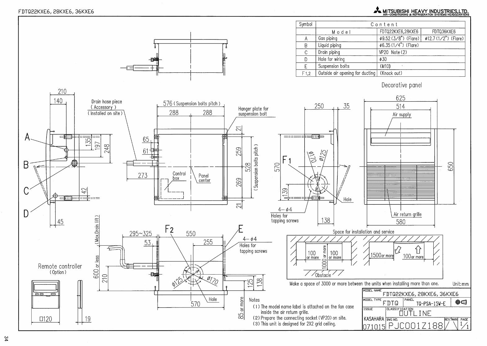
FDTQ22KXE6FDTQ28KXE6FDTQ36KXE6
FDTS45KXE6FDTS71KXE6
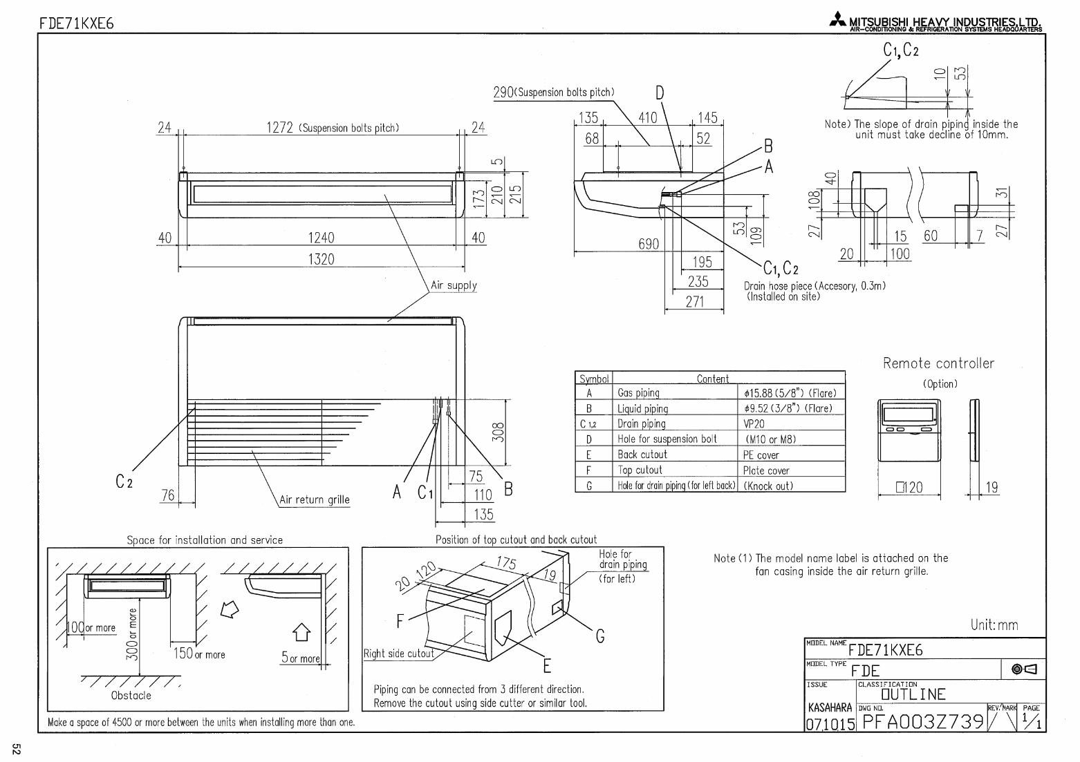
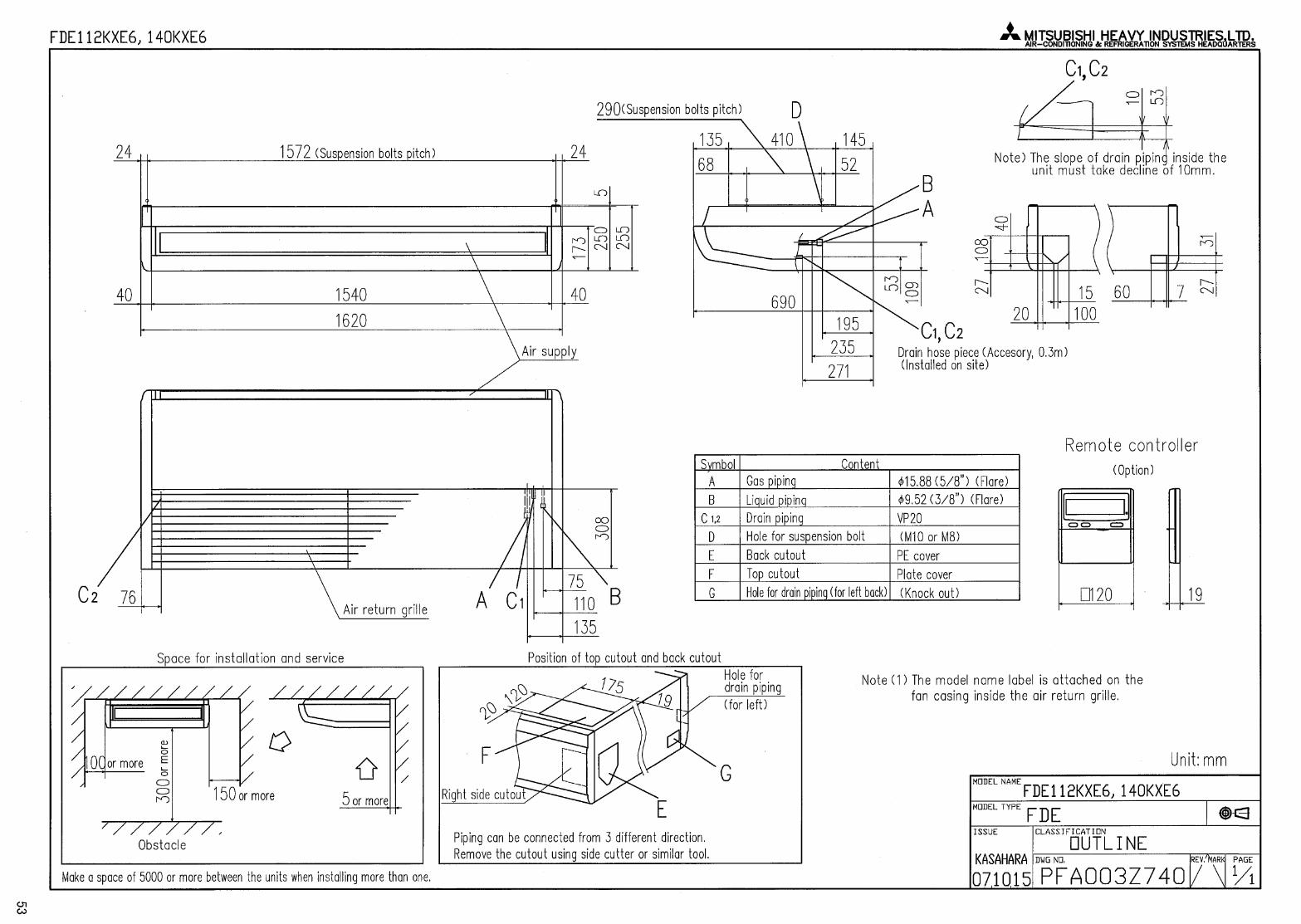
FDE36KXE6FDE45KXE6FDE56KXE6FDE71KXE6FDE112KXE6FDE140KXE6
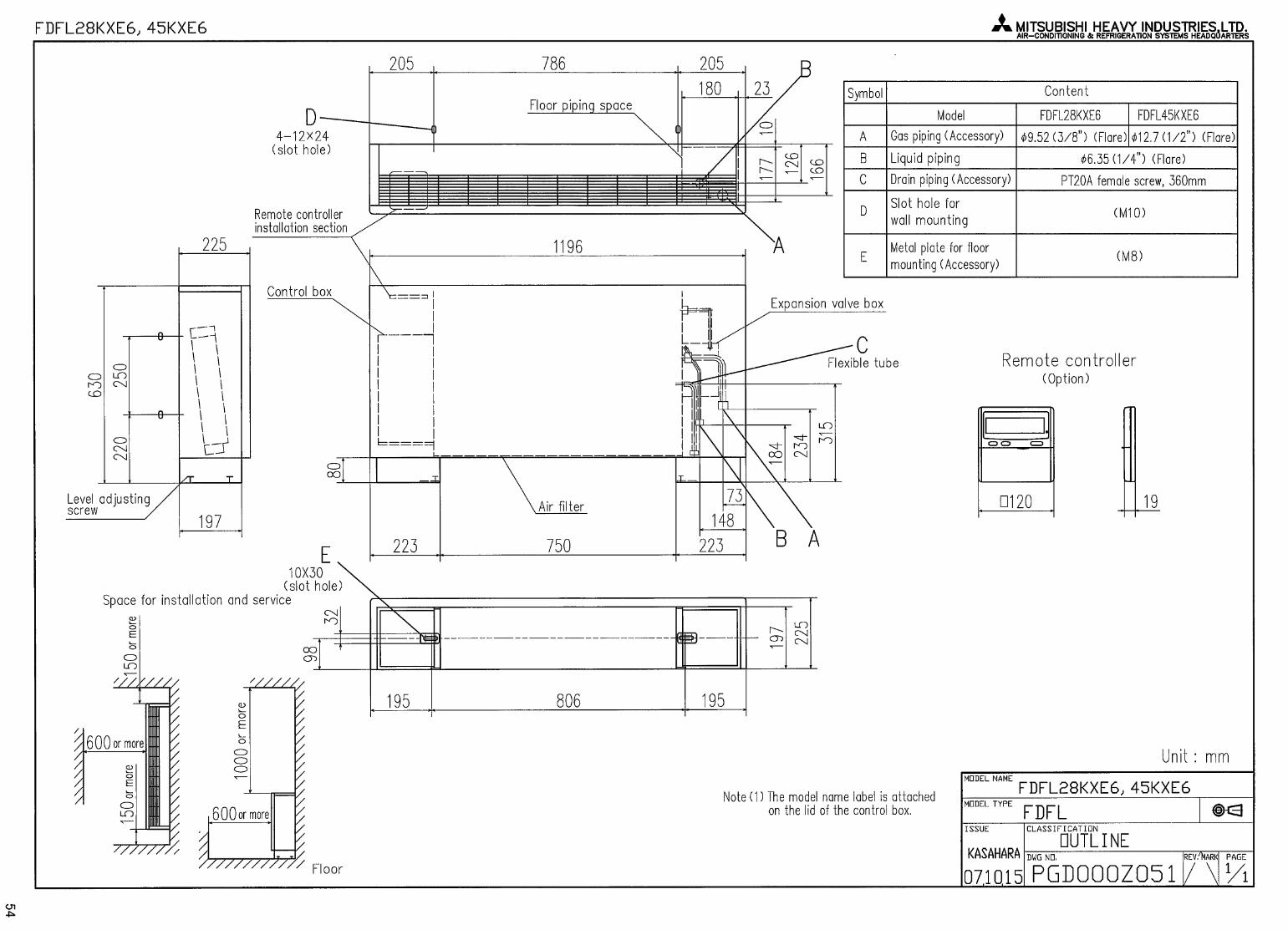
FDFL28KXE6FDFL45KXE6FDFL71KXE6
FDFU28KXE6FDFU45KXE6FDFU56KXE6FDFU71KXE6
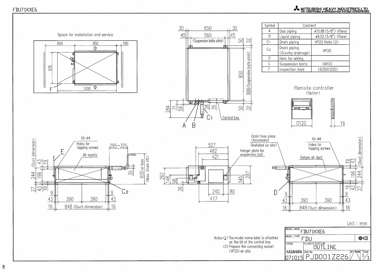
FDU71KXE6FDU90KXE6FDU112KXE6FDU140KXE6FDU224KXE6FDU280KXE6
FDUM22KXE6FDUM28KXE6FDUM36KXE6FDUM45KXE6FDUM56KXE6FDUM71KXE6FDUM90KXE6FDUM112KXE6FDUM140KXE6
FDQS22KXE6FDQS28KXE6FDQS36KXE6FDQS45KXE6FDQS56KXE6
FDK22KXE6FDK28KXE6FDK36KXE6FDK45KXE6FDK56KXE6FDK71KXE6
�
FDC112KXEN6 (1phase)FDC140KXEN6 (1phase)FDC155KXEN6 (1phase)
FDC112KXES6 (3phase)FDC140KXES6 (3phase)FDC155KXES6 (3phase)
�
(INDOOR UNIT)
Spec Sheet
CONTENTS
1. OUTDOOR UNIT
1.2 Specifications 2 page
2.2 Exterior dimensions 3
2.3 Electrical wiring 4
2. INDOOR UNIT
2.1 Specifications
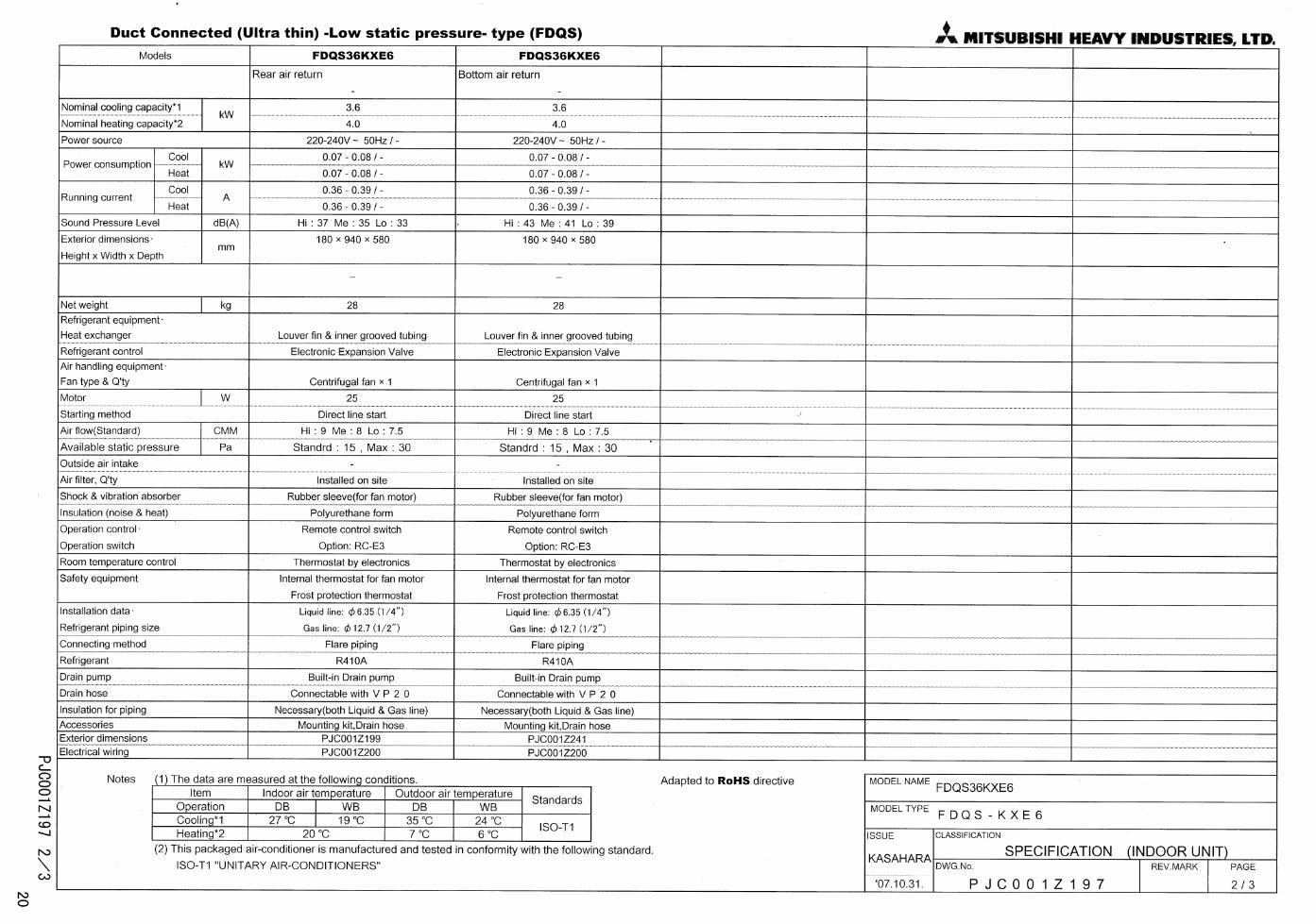
(a) Ceiling Cassette -4way- (FDT) 6(b) Ceiling Cassette -4way- Compact (600x600mm) (FDTC) 8(c) Ceiling Cassette -2way- (FDTW) 9(d) Ceiling Cassette -1way Compact- (FDTQ) 11(e) Ceiling Cassette -1way- (FDTS) 14(f) Duct Connected -High Static Presuure- (FDU) 15(g) Duct Connected -Low/middle Static Pressure- (FDUM) 17(h) Duct Connected (Ultra thin) -Low Static Presure- (FDQS) 19(i) Wall Mounted (FDK) 22(j) Ceiling Suspended (FDE) 24(k) Floor Standing (with casing) (FDFL) 26(l) Floor Standing (without casing) (FDFU) 27
2.2 Exterior dimensions 28
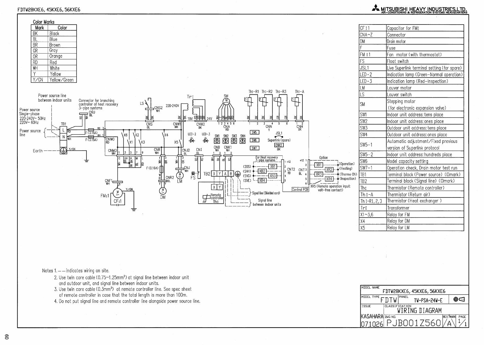
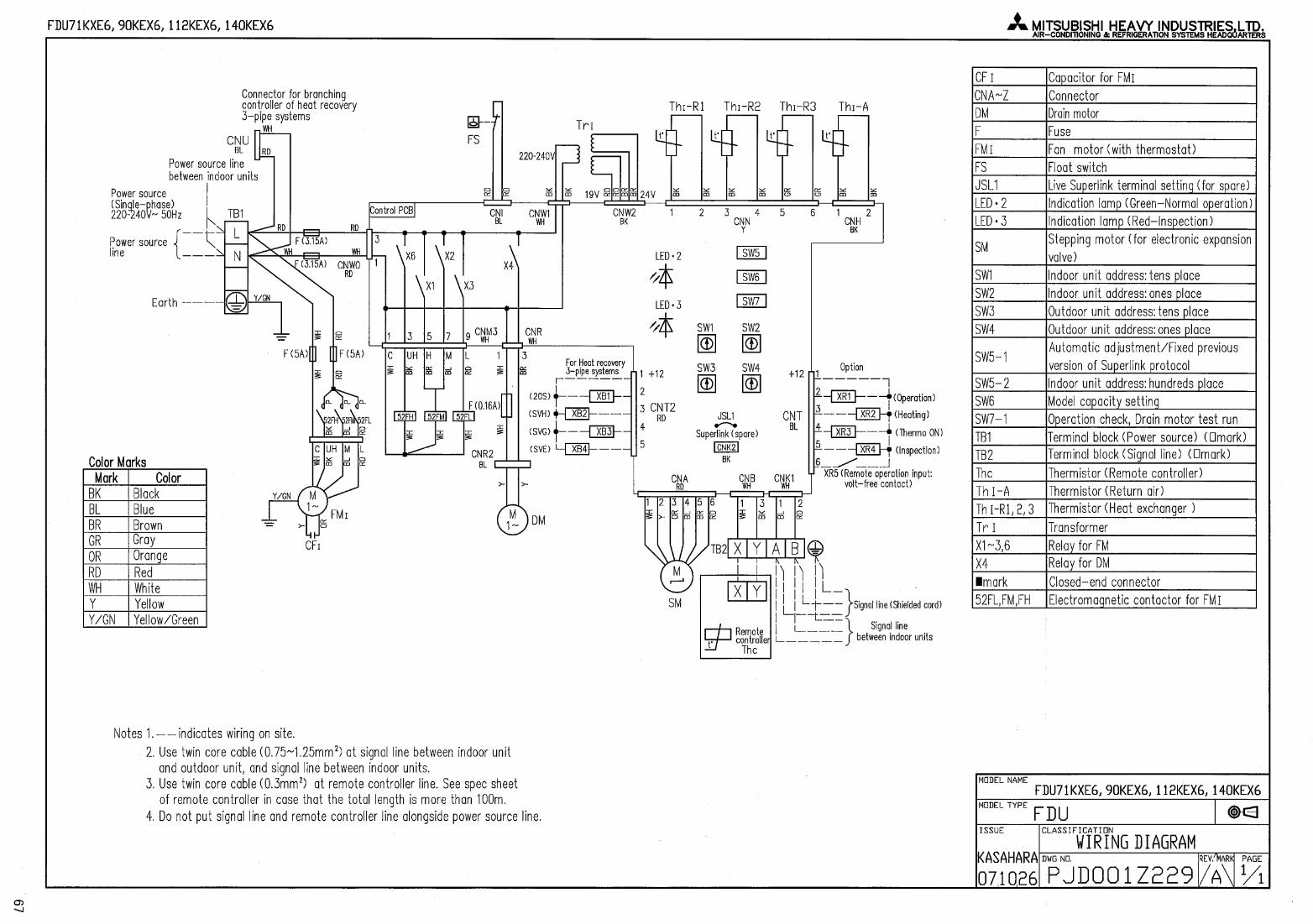
2.3 Electrical wiring 58
3. Refrigerant cycle 78
1
・ MITSUBISHI HEAVY INDUSTREIES,LTD.
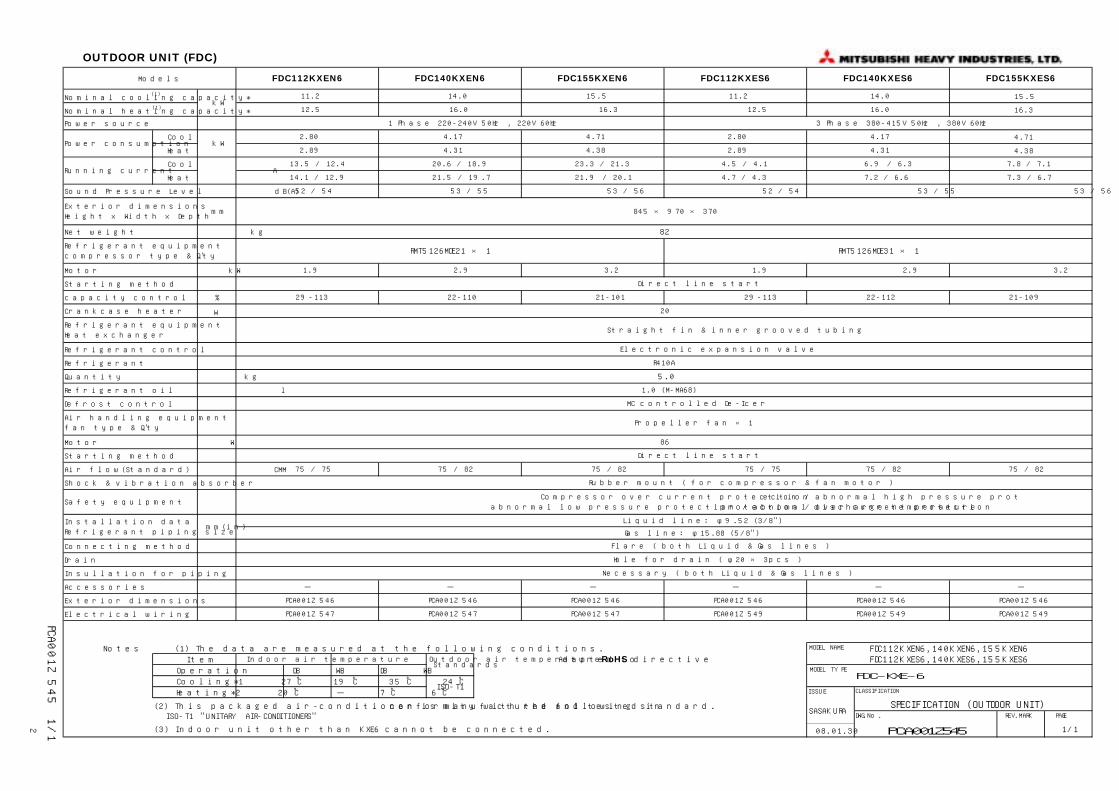
Models FDC112KXEN6 FDC140KXEN6 FDC155KXEN6 FDC112KXES6 FDC140KXES6 FDC155KXES6
Nominal cooling capacity*(1) 15.5
Nominal heating capacity*(1) 16.3
Power source
Cool 4.71
Heat 4.38
Cool
Heat
Sound Pressure Level dB(A)
Exterior dimensions
Height x Width x Depth
Net weight kg
Refrigerant equipment
compressor type & Q'ty
Motor kW
Starting method
capacity control %
Crankcase heater W
Refrigerant equipment
Heat exchanger
Refrigerant control
Refrigerant
Quantity kg
Refrigerant oil l
Defrost control
Air handling equipment
fan type & Q'ty
Motor W
Starting method
Air flow(Standard) CMM
Shock & vibration absorber
Installation data
Refrigerant piping size
Connecting method
Drain
Insullation for piping
Accessories
Exterior dimensions
Electrical wiring
Notes (1) The data are measured at the following conditions. MODEL NAME
Item Adapted to RoHS directive
Operation DB WB DB WB MODEL TYPE
Cooling*1 27 ℃ 19 ℃ 35 ℃ 24 ℃
Heating*2 20 ℃ - 7 ℃ 6 ℃ ISSUE CLASSIFICATION
(2) This packaged air-conditioner is manufactured and tested in conformity with the following standard. ISO-T1 "UNITARY AIR-CONDITIONERS" DWG.No. REV.MARK PAGE
2 (3) Indoor unit other than KXE6 cannot be connected. 08.01.30 PCA001Z545 1/1
Direct line start
Direct line start
Rubber mount ( for compressor & fan motor )
86
Propeller fan × 1
1.0 (M-MA68)
Straight fin & inner grooved tubing
5.0
75 / 75
22-112
Necessary ( both Liquid & Gas lines )
Hole for drain ( φ20 × 3pcs )
Flare ( both Liquid & Gas lines )
MC controlled De-Icer
75 / 82
21-109
Compressor over current protection / abnormal high pressure protection
abnormal low pressure protection / abnomal discharge temperature protection / over current protection
29-113 22-110 21-101 29-113
75 / 82 75 / 82 75 / 75
16.0
1 Phase 220-240V 50Hz , 220V 60Hz 3 Phase 380-415V 50Hz , 380V 60Hz
52 / 54 53 / 55 53 / 56 52 / 54 53 / 55 53 / 56
4.31
PCA001Z546
PCA001Z547PCA001Z547
PCA001Z546
PCA001Z547
PCA001Z546
4.17
SPECIFICATION (OUTDOOR UNIT)
PCA001Z546
PCA001Z549
PCA001Z546
PCA001Z549
PCA001Z546
PCA001Z549
845 × 970 × 370
82
mm(in)
Indoor air temperature Outdoor air temperature
Power consumption
Running current A
mm
kW2.80
2.89
PC
A001Z545
1/1
Standards
ISO-T1
SASAKURA
FDC112KXEN6,140KXEN6,155KXEN6FDC112KXES6,140KXES6,155KXES6
FDC-KXE-6
14.0
6.9 / 6.3
7.2 / 6.6
7.8 / 7.1
7.3 / 6.7
20
R410A
kW11.2 14.0 11.215.5
12.5 16.0 16.3 12.5
4.71
4.38
2.80
2.89
4.17
4.31
13.5 / 12.4
14.1 / 12.9
20.6 / 18.9
21.5 / 19.7
23.3 / 21.3
21.9 / 20.1
4.5 / 4.1
4.7 / 4.3
Safety equipment
RMT5126MDE21 × 1 RMT5126MDE31 × 1
Electronic expansion valve
1.9 2.9 3.2 1.9 2.9 3.2
OUTDOOR UNIT (FDC)
75 / 82
- - - -
Liquid line: φ9.52 (3/8")
Gas line: φ15.88 (5/8")
- -

Minimum installation space
Intake
outlet
Intake
Servicespace
L1
L2L3
L4
A51
40 36
100
845
10
110
50
195 24
2
279
970
50 15
55
5027
52
110
50
195
B
B
A
A
Terminal block
F
CC
VIEW AC 5015
7050
150
40
F
E
370
4040
410
2020
55
60
388262
38
60
190 580 200
60 15
103
15
C
D
DimensionsAll measurements in mm.
Mark Item
Service valve connection (gas side)
Service valve connection (liquid line)
Pipe/cable draw-out port
Drain discharge port
Anchor bolt hole
Cable draw-out port
Notes:(1) It must not be surrounded by walls on the four sides.(2) The unit must be fixed with anchor bolts. An anchor bolt must not protrude more than 15mm.(3) Where the unit is subject to strong winds, lay it in such a direction that the blower outlet faces perpendicularly to the dominant wind direction.(4) Leave a 1m or larger space above the unit.(5) A wall in front of the blower outlet must not exceed the units height.(6) The unit name plate is attached on the lower right corner of the front panel.
A
B
C
D
E
F
ø5/8" (15.88) (flare)
ø3/8" (9.52) (flare)
4 places
ø20 x 3 places
M10 x 4 places
ø30 x 3 places
1m overhead clearance required
I
Open
300
150
5
II
Open
5
300
5
II
500
Open
150
5
L1
L2
L3
L4
FDC 112/140/155 KXEN6FDC 112/140/155 KXES6
3

LINE IN Tho-SC Tho-H Tho-P1Tho-ATho-STho-D1Tho-R163H1-1
LINE OUT BK
BK
BK
BK
BK
BK
BK
BK
BK
BK
BK
BK
BK
BK
(WH)CNR1
(RD)CNN1
(BR)CNQ1
(BK)CNS1
(RD)CNZ1
(WH)CNTH
(WH)CNF1
(GN)CNF2
(Y)CNP1
YYBK
BK
20SCH1
BR
RD RDBR
tû tû tûtûtûtû tû
(BK)CNX2
(Y)CNX1
(BK)CNW
(WH)CNFAN1
(BL)CNEEV2
(RD)CNEEV1
(WH)CNL2
(BL)CNL1
(WH)CNA1
(GN)CNA2
(WH)CNI1
(WH)CNI3
PWB1
PCBCONTROL
J10
SW9SW8
J15J13
CHECKER
CNE CNV
(RS232C)PC
LED1
LED3LED2
SW7
7SEG SW4
OFF
ON
SW5
SW3
ON
OFF
SW2SW1
4 75 6 821 3 6 75 842 3
8
1
65 71 2 3 4
BK RDWH
PSLPSH
BK RDWH
WH
BL
OR
RD BR
Y
M
FMo1
RDBL
4 1
OR
WH
67 5
BR
M
EEVSCEEVH
M
2 1
WH
1 56 4 3
BL
OR
RD BR
6 5 4 3 2
Y
WH
BK
WH
BK
WH
WH
RD
WH
RD BK
WH
BK
BK
E2
GN
WH
WH
GN GN
NoL1o
Ni
L1iRD
PWB3
FILTERNOISE
F1(30A)
WH
RD
CONNECTORNETWORK
CM
CNSL1,2
B2
CT
L1
TB
N
A1
TB
B1
A2
(WH)CN1
(Y)CN2
E1
(WH)CNI4(WH)CNI2
(WH)CNACT1
BL
RD WH
BL
RD
BL
RDPL2L1
PCB
PWB2
INVERTER
-
+
MODULEA/F
BL
F3 (4A/250V)BL
RD
BL
RD
BL
RDRD
BL
BL
U WV
TB2TB1 TB5
+C1
TB10
TB6
TB11
L1
I P M
TB9TB8
MS3~CM1
TB7
N2
DM
CM1
POWER SOURCE
1~220-240V50Hz1~220V 60Hz
Earth leakage breaker
Circuit breaker
V (WH)W (BL)
U (RD)
CM
Mark Color
Color mark
2. Error Indication
3. 7-segment display
1. Instructions for correct operation
Name
BRRDWHBL
BrownRedWhiteBlue
Mark ColorBKORYY/GN
BlackOrangeYellowYellow/Green
Before you turn on power, please carefully read the installation manual and the operation manual supplied with the unit.
Please check the following points before operation.
This unit is designed exclusively for use with R410A. Do not use any refrigerant other than R410A.
To protect the compressor, turn on power for the air conditioner 6 hours before operation so as to warm up sufficiently the dome temperature of compressor.
Open the service valve of liquid pipe at first. Secondarily open the one of gas pipe. Before you operate the unit, make sure again that the service valve are in open position.
Please note that the pressure values detected at the charge port in the unit and the gas service valve are different during the cooling operation and the heating operation. High pressure is replaced with the low pressure depending on whether it is in the cooling or heating operation.
You should test run the unit before starting normal operation to see if the addresses are set correctly and if the indoor electronic expansion valve operates properly. For more information, please refer to the technical manual.
1
2
3
4
5
Select the code No. for each item by pressing SW9 for ten's place and SW8 for one's place.
Electrolytic capacitorCrankcase heaterCompressor motorConnectorCurrent sensorDiode moduleElectronic expansion valve (For overcooling)Electronic expansion valve (For heating)Fan motorFuseHigh pressure sensorIntelligent power moduleSuperlink terminal setting (spare/normal)External input switch (pulse/level)Defrost start temperature (cold weather district/normal)ReactorIndicator lamp (Red-Inspection indicator)Indicator lamp (Green-Microcomputer normality indication)Indicator lamp (Green-For service)Low pressure sensorOutdoor unit No. (ten's place number)Outdoor unit No. (one's place number)Inspection LED resetCheck operation startForced cooling/heating switchingDemand switchingDemand switchingTest run start (normal/start)Test run cooling setting (heating/cooling)Pump down (normal/valid)Superlink protocol setting (new/previous)Data erasing/writing7-seg display UP, one's place number7-seg display UP, ten's place numberTerminal boardThermistor (outdoor air temperature)Thermistor (discharge pipe)Thermistor (power transistor)Thermistor (heat exchanger)Thermistor (suction pipe)Thermistor (sub-cooling coil, l iquid)Thermistor (sub-cooling coil, gas)4-way valve coilHigh pressure switch (Protection)
Code No. Item displayedCM1 operation frequencyTho-A outdoor air temperatureTho-R1 heat exchanger temperature 1Tho-D1 discharge pipe temperature (CM1)Tho-P1 power transistor temperature (CM1)Tho-SC overcooling coil temperature 1Tho-H overcooling coil temperature 2Tho-S suction pipe temperatureCT1 (CM1) currentEEVH heating expansion valve apertureEEVSC overcooling coil expansion valve apertureFM01 actual r.p.m.PSH high pressure sensorPSL low pressure sensorNumber of connected indoor unitsCapacity of connected indoor unitsNumber of indoor units with thermostat ONTotal request frequencyIntegrated time of compressor operation (CM1)
Green Red Outdoorunit LED 7-segment
displayInspection
Cont .
Cont .
Cont .
Cont .
Cont .
Cont .Cont .Cont .Cont .Cont .
Cont .
Cont .
Cont .
Cont .Cont .Cont .Cont .
Cont .
Cont .
Cont .Cont .Cont .Cont .
E30
E31
E32
E36
E37
E38E39E40E41E42
E43
E45
Ð
E48E49E51E53
E54
E56
E58E59E60E63
Unmatched indoor/outdoor connectionDuplicating outdoor unit address No.Outdoor unit address setting errorPower supply phase interruptionTd error (Tho-D1)Liquid pack errorHeat exchanger sensor 1 disconnection (Tho-R1)Overcooling coil sensor 1 disconnection (Tho-SC)Overcooling coil sensor 2 disconnection (Tho-H)Outdoor air temperature sensor disconnection (Tho-A)Td sensor 1 disconnection (Tho-D1)High pressure switch operation (63H1-1)Power transistor overheat (CM1) (5-time/hour)Current cut (CM1)Too many units connectedToo many units connected beyond capacityTransmission error between inverter and outdoor unit PCB (CM1)Auto address and remote control address are mixed in the same network.FM01 errorLow pressure error (PSL operated)Power transistor overheat (CM1) (Continued for 15 min.)Suction pipe temperature sensor disconnection (Tho-S)Low pressure sensor disconnection (PSL)/output error High pressure sensor disconnection (PSH)/output errorPower transistor temperature sensor 1 disconnection (Tho-P1)Active filter temperature sensor disconnectionAnomalous compressor induced voltage and torque (CM1)Compressor startup error (CM1)Compressor position detection error (CM1)Outdoor unit emergency stop error
C00C02C03C07C12C14C15C16C18C20C22C23C25C26C40C41C42C43C44
Mark CCHCMCNA~ZCTDMEEVSCEEVHFMo1FPSHIPMJ10J13J15LLED1LED2LED3PSLSW1SW2SW3-1SW3-5SW3-7SW4-7SW4-8SW5-1SW5-2SW5-3SW5-5SW7 (Button)SW8 (Button)SW9 (Button)TBTho-ATho-DTho-P1Tho-R1Tho-STho-SCTho-H20S63H1-1
B2
B1A1
A2BETWEEN THE OUTDOOR UNITSBETWEEN THE INDOOR UNIT AND THE OUTDOOR UNITSIGNAL
LINE
1-t ime
1-t ime
1-t ime1-t ime3-t ime1-t ime5-t ime6-t ime1-t ime1-t ime1-t ime1-t ime1-t ime1-t ime2-t ime1-t ime
Dark
1-t ime1-t ime1-t ime1-t ime1-t ime2-t ime1-t ime3-t ime1-t ime1-t ime1-t ime1-t ime
FDC 112/140/155 KXEN6
4

(WH)CNW1
RD
BK
(WH)CNW2
RD
BL
(WH)CNR
BL
RD
(RD)CNO1
G
K
~~
~
(WH)CNI2
BL
RD WH
BK
GL
PWB2PCB
INVERTER BL
RD
BLBL
DM
R1
R2U
+
C1
-+
U WV
TB5
+
C2
TB6
L1
I P MTB9TB8
3~CM1
TB7
MS
WH
BL
(GR)CNM1
(WH)CNA1
(GN)CNA2
(WH)CNI1
F3 (4A/250V)
BL
RD
BL
RD
PWB1PCB
CONTROL
LINE OUT BK
BK
BK
BK
BK
BK
BK
BK
BK
BK
BK
BK
BK
BK
(WH)CNR1
(RD)CNN1
(BR)CNQ1
(BK)CNS1
(RD)CNZ1
(WH)CNTH
(WH)CNF1
(GN)CNF2
(Y)CNP1
YYBK
BK
BR
RD RDBR
LINE IN Tho-SC Tho-H Tho-P1Tho-ATho-STho-D1Tho-R163H1-1
20SCH1
V (WH)W (BL)
U (RD)
CM
tûtûtûtûtûtûtû
SW9SW8SW7
4 75 6 8
SW4
OFF
ON
21 3
SW5
6 75 842 3
8
1
65 71 2 3 4
ON
OFF
SW3
J10 J15J13
CHECKER
CNE CNV
(RS232C)PC
LED1
LED3LED2
(BK)CNX2
(Y)CNX1
(BK)CNW
(WH)CNFAN1
(BL)CNEEV2
(RD)CNEEV1
(WH)CNL2
(BL)CNL1
7SEG
SW2SW1
WH
BL
OR
RD BR
Y RDBL
4 1
OR
WH
67 5
BR
2 1
WH
1 56 4 3
BL
OR
RD BR
6 5 4 3 2
Y
M
FMo1
M
EEVSCEEVH
M
BK
WH
BK
WH
BK
WH
WH
RD BK
WH
BK RDWH
CONNECTORNETWORK
PSLPSH
BK RDWH
CNSL1,2
B2
A1
TB
B1
A2
BK
BL
65
BL
L3o
WH
L2oN
(WH)CN1
(Y)CN2-2
BK
RD
BK
BKL3i
WH
WH
GN
E1GN
NoL1o
L2i
L1iRD
PWB3FILTERNOISEWH
RD
52C
L1
L2
CT
L3
TB
NPOWER SOURCE3N~380-415V50Hz3N~380V 60Hz
Earth leakage breaker
Circuit breaker
B2
B1A1
A2BETWEEN THE OUTDOOR UNITSBETWEEN THE INDOOR UNIT AND THE OUTDOOR UNIT
SIGNAL LINE
Mark
Color mark
BRRDWHBL
ColorBrownRedWhiteBlue
MarkBKORYY/GN
ColorBlackOrangeYellowYellow/Green
3. 7-segment display
Select the code No. for each item by pressing
SW9 for tenÕs place and SW8 for oneÕs place.
Code No. Item displayed
2. Error Indication1. Instructions for correct operation
Before you turn on power, please carefully read the installation manual and the operation manual supplied with the unit.
Please check the following points before operation.
This unit is designed exclusively for use with R410A. Do not use any refrigerant other than R410A.
To protect the compressor, turn on power for the air conditioner 6 hours before operation so as to warm up sufficiently the dome temperature of compressor.
Open the service valve of liquid pipe at first. Secondarily open the one of gas pipe. Before you operate the unit, make sure again that the service valve are in open position.
Please note that the pressure values detected at the charge port in the unit and the gas service valve are different during the cooling operation and the heating operation. High pressure is replaced with the low pressure depending on whether it is in the cooling or heating operation.
You should test run the unit before starting normal operation to see if the addresses are set correctly and if the indoor electronic expansion valve operates properly. For more information, please refer to the technical manual.
1
2
3
4
5
Green RedOutdoorunit LED 7-segment
displayInspection
C00C02C03C07C12C14C15C16C18C20C22C23C25C26C40C41C42C43C44
CM1 operation frequencyTho-A outdoor air temperatureTho-R1 heat exchanger temperature 1Tho-D1 discharge pipe temperature (CM1)Tho-P1 power transistor temperature (CM1)Tho-SC overcooling coil temperature 1Tho-H overcooling coil temperature 2Tho-S suction pipe temperatureCT1 (CM1) currentEEVH heating expansion valve apertureEEVSC overcooling coil expansion valve apertureFM01 actual r.p.m.PSH high pressure sensorPSL low pressure sensorNumber of connected indoor unitsCapacity of connected indoor unitsNumber of indoor units with thermostat ONTotal request frequencyIntegrated time of compressor operation (CM1)
Mark NameElectrolytic capacitorCrankcase heaterCompressor motorConnectorCurrent sensorDiode moduleElectronic expansion valve (For overcooling)Electronic expansion valve (For heating)Fan motorFuseHigh pressure sensorIntelligent power moduleSuperlink terminal setting (spare/normal)External input switch (pulse/level)Defrost start temperature (cold weather district/normal)ReactorIndicator lamp (Red-Inspection indicator)Indicator lamp (Green-Microcomputer normality indication)Indicator lamp (Green-For service)Low pressure sensorOutdoor unit No. (tenÕs place number)Outdoor unit No. (oneÕs place number)Inspection LED resetCheck operation startForced cooling/heating switchingDemand switchingDemand switchingTest run start (normal/start)Test run cooling setting (heating/cooling)Pump down (normal/valid)Superlink protocol setting (new/previous)Data erasing/writing7-seg display UP, oneÕs place number7-seg display UP, tenÕs place numberTerminal boardThermistor (outdoor air temperature)Thermistor (discharge pipe)Thermistor (power transistor)Thermistor (heat exchanger)Thermistor (suction pipe)Thermistor (sub-cooling coil, liquid)Thermistor (sub-cooling coil, gas)4-way valve coilHigh pressure switch (Protection)
CCHCMCNA~ZCTDMEEVSCEEVHFMo1FPSHIPMJ10J13J15LLED1LED2LED3PSLSW1SW2SW3-1SW3-5SW3-7SW4-7SW4-8SW5-1SW5-2SW5-3SW5-5SW7 (Button)SW8 (Button)SW9 (Button)TBTho-ATho-DTho-P1Tho-R1Tho-STho-SCTho-H20S63H1-1
Cont.
Cont.
Cont.
Cont.
Cont.
Cont.Cont.Cont.Cont.Cont.
Cont.
Cont.
Cont.
Cont.Cont.Cont.Cont.
Cont.
Cont.
Cont.Cont.Cont.Cont.
1-time
1-time
1-time1-time3-time1-time5-time6-time1-time1-time1-time1-time1-time1-time2-time1-time
Dark
1-time1-time1-time1-time1-time2-time1-time3-time1-time1-time1-time1-time
E30
E31
E32
E36
E37
E38E39E40E41E42
E43
E45
Ð
E48E49E51E53
E54
E56
E58E59E60E63
Unmatched indoor/outdoor connectionDuplicating outdoor unit address No.Outdoor unit address setting errorPower supply phase interruptionTd error (Tho-D1)Liquid pack errorHeat exchanger sensor 1 disconnection (Tho-R1)Overcooling coil sensor 1 disconnection (Tho-SC)Overcooling coil sensor 2 disconnection (Tho-H)Outdoor air temperature sensor disconnection (Tho-A)Td sensor 1 disconnection (Tho-D1)High pressure switch operation (63H1-1)Power transistor overheat (CM1) (5-time/hour)Current cut (CM1)Too many units connectedToo many units connected beyond capacityTransmission error between inverter and outdoor unit PCB (CM1)Auto address and remote control address are mixed in the same network.FM01 errorLow pressure error (PSL operated)Power transistor overheat (CM1) (Continued for 15 min.)Suction pipe temperature sensor disconnection (Tho-S)Low pressure sensor disconnection (PSL)/output error High pressure sensor disconnection (PSH)/output errorPower transistor temperature sensor 1 disconnection (Tho-P1)Active filter temperature sensor disconnectionAnomalous compressor induced voltage and torque (CM1)Compressor startup error (CM1)Compressor position detection error (CM1)Outdoor unit emergency stop error
5
FDC 112/140/155 KXES6


Refrigerant cycle
Model:FDC112,140,155KXEN6FDC112,140,155KXES6
78
Check valve
Oil separater
(63H1-1)(PSH)
Check joint4-way valve
Service valve
Service valveGas piping(φ15.88)
Liquid piping(φ9.52)
Thermister(Tho-D1)
Outdoor unit
To next unit by turn
Themister(Air))
Themister(Inlet)
Indoor unit A
(Thi-A)
(Thi-R2)
ReceiverEEV
Thermister(Air)
Thermister(Inlet)
Indoor unit B
(Thi-A)
(Thi-R2)
Thermister(Outlet)(Thi-R3)
Thermister(Outlet)
(Thi-R3)Thermister(Heat exchanger)
(Thi-R1)
Thermister(Heat(Thi-R1)
(PSL)
CM
Thermister(THo-S)
Thermister1(THo-SC)
Low pressure sensor
High pressure High pressure
ST
EEV
HST
STST
STST
EEV
ST
ST
(Tho-H
)
Thermistor 2
Sub-coolingil
EEVSC
<Main parts>Compressor:RM-T5126(Twin rotary)EEVH:SSA387F039A (FUJIKOKI Valve apertureφ3.0mm) SSA382F212KEEVSC: SSA387F031(FUJIKOKI Valve apertureφ1.5mm) SSA382F210ADReceiver:SSA352B045 (2.5L)Sub-cooling coil:PCA303A001 (double tube:1153mm)High pressure sensor:SSA551D024A (Check joint attached for pin)Low pressure sensor:SSA551D022B (Check joint attached for pin)Oil return capillary:OD2.0XID0.9XL500
Compressoraccumulator
Charge port
Charge port
Muffler
EEV:Electric expansioin valveST:Strainer
Heat exchanger
Heat exchanger
Compressor
Heat exchanger
Themister(Air)) (Tho-A)
(Tho-R1)
Sub-coolingcCoil
Thermister(Heat exchanger)