SPE 168271 Tubing Retrievable Surface Controlled ... · PDF fileSPE 168271 Tubing Retrievable...
27
SPE 168271 Tubing Retrievable Surface Controlled Subsurface Safety Valve Floating Flapper Remediation B. Gary, Halliburton; C. Hosli, Shell; A. Luviano, Welltec; J. Langley, Expro
Transcript of SPE 168271 Tubing Retrievable Surface Controlled ... · PDF fileSPE 168271 Tubing Retrievable...

SPE 168271
Tubing Retrievable Surface Controlled Subsurface
Safety Valve Floating Flapper Remediation
B. Gary, Halliburton; C. Hosli, Shell;
A. Luviano, Welltec; J. Langley, Expro

SLIDE TITLE HERE
• Introduction
• TRSCSSV Flapper Obstruction and Failed Operation
• Toolstring Development and Testing
• Operational Deployment
• Conclusions and Observations
Slide 2
Presentation
Agenda

SLIDE TITLE HERE
Slide 3
Introduction
• Conventional offshore completions require a “subsurface safety device.”
•Surface-controlled subsurface safety valve (SCSSV)
•Subsurface-controlled subsurface safety valve (SSSSV)
•Injection valve
•Tubing plug
•Tubing/annular subsurface safety device
• During through-tubing operations (wireline, CT etc.), the SV can be
damaged due to
•Improper equalization before opening
•Toolstring running speed – if valve is not properly locked open
• Damage specific to flapper-type valve – shearing of the hinge pin

SLIDE TITLE HERE
Slide 4
Introduction
• Traditional intervention – Slickline rotating wedge with hold open sleeve
• Rotate wedge to bypass flapper
• Set open sleeve in SV profile
• Set device (retrievable packer, stop) to secure sleeve
• Method would allow for:
• Toolstring deployment past the obstruction
• Future up-hole recompletion operations
• Case History consists of:
• Initial attempt to bypass broken flapper
• Five full-scale tests on four different BHA’s – one SL and three EL
• Successful operation to insert isolation sleeve across flapper
obstruction

SLIDE TITLE HERE
• Introduction
• TRSCSSV Flapper Obstruction and Failed Operation
• Toolstring Development and Testing
• Operational Deployment
• Conclusions and Observations
Slide 5
Presentation
Agenda

SLIDE TITLE HERE
Slide 6
TRSCSSV Flapper Obstruction
and Failed Operation
Vertical Access Well in Deepwater Gulf of Mexico – Sequence of events
• 2006 – SL ran 2” LIB – Tagged up on SV flapper @ 6,008-ft. MD
• 2010 – ran memory camera
• 2012 – decision made to re-complete well
• Problem – needed to by-pass broken flapper to make three runs:
• 2.20 inverted gauge
• 2.125 inch OD inflatable bridge plug
• 2.188-in mechanical tubing cutter
• 2013 – successfully developed, tested and deployed bypass device across
obstruction

SLIDE TITLE HERE
Slide 7
TRSCSSV Flapper Obstruction
and Failed Operation
Initial Well Diagnostics (2006)
• Ran 2-in. SL LIB
• 4.5-in. TRSCSSV flapper @ 6,008-ft. MD broken off hinge
• Impression of flapper in “top up” position
• Root cause unidentified
• Installed Wireline Retrievable SV in 3.562-in. RPT profile of TRSCSSV

SLIDE TITLE HERE
Slide 8
TRSCSSV Flapper Obstruction
and Failed Operation
Camera Deployment (2010)
• Flapper in “top up” position
• Minimal paraffin deposition
• Flapper “floating” in cavity below
hinge tabs
• Lower Seal Bore (and rest of
completion) Blocked

SLIDE TITLE HERE
Slide 9
TRSCSSV Flapper Obstruction
and Failed Operation
Pre-Rig Intervention Objectives
1. Bypass flapper for 2.200-in. Inverted Gauge, 43.5-ft x 2.125-in. IBP, and run a 2.188-
in. mechanical cutter,
2. Secure bypass device for continued production / well intervention – A Stop
3. Reinstall 3.660-in. ML BP x 2.5-in. PB-WRSCSSV

SLIDE TITLE HERE
Conventional Intervention/1st Attempt
•SL, paraffin cleaning required, flag NO-GO run
•90o Ratcheting Flapper Manipulation Tool
•3.560-in. Hold Open Sleeve (HOS)
•12.3-ft. HOS Barrel Length
•Pinned Shear Sub
Results
•Friction Locked in RPT profile
•Flapper Top Up vs Flapper Bottom Up
•Multiple LIB deployments & flow periods
•HOS end damaged from impact
Slide 10
TRSCSSV Flapper Obstruction
and Failed Operation

SLIDE TITLE HERE
Slide 11
TRSCSSV Flapper Obstruction
and Failed Operation
•Learnings
1. Flowing well at 10–15% choke/impacting the flapper with the FMT wedge could flip
the flapper
2. “Flapper Bottom Up” position might be a more convenient isolation orientation
3. Flagged depth accuracy from the original 3.650-in. no-go was critical for both wedge
interaction vs HOS insertion and to verify RPT location
4. FMT impact location had a significant effect on whether the toolstring would be
caught by the hinge tabs or if the flapper would recess flush
•Target
•Closing Pre Rig Window – But No Plan Otherwise
•Pass 3 toolstrings to access 3.5-in., 9.2 ppf 13CR cut joints at 15,995–ft MD
1. 2.200-in Inverted Gauge
2. 43.5-ft x 2.125-in IBP
3. 2.188-in. mechanical cutter
15,954.00 41.62 1 Adpt Assy Joint - 3 1/2" 9.2# 13Cr 95my Varst-1 3.500 2.992 15,858.02
15,995.62 41.64 1 Tubing - 3 1/2" 9.2# 13Cr 95my Varst-1 (2 Joints) 3.500 2.992 15,899.64
SLIDE TITLE HERE
• Introduction
• Case History Background
• TRSCSSV Flapper Obstruction and Failed Operation
• Toolstring Development and Testing
• Operational Deployment
• Conclusions and Observations
Slide 12
Presentation
Agenda

SLIDE TITLE HERE
Slide 13
Toolstring Development
and Testing
1st (of 5) Toolstrings “Developed” and “Tested”
• January 2013
• EL “cannon”
• Inconel 718 Flappers – material currently in well
• Shrapnel Remnants – too large
• Not a viable option

Slide 14
Toolstring Development
and Testing
Test Fixture Procurement and Construction
• Operator inventory
• Concentric confinement, full BHA containment, 0 deg inclination, 2 test wells secured
•EL “cannon”
•Inconel 718 Flappers
•Schrapnel Remnants
•Not well documented
(in) (ft)Slips Slips for 4.5” 15.10# (Can use elevator to lift into place)
Pup Joint 4.5” 15.10# (Grade not critical, ID critical) 3.826 10.00
CouplingCoupling to mate pup joint to 4.5" joint tubing (Grade not
critical, ID critical)
3.826 (sized to mate to
tubing and pup joint) 1.00
Pup Joint4.5” 15.10# 13cr95y pup joints x 10’ long (Grade not critical,
ID critical) 3.826 10.00
Upper Restriction Upper SCSSV Assembly Restriction 3.562 1.17
SCSSV Upper Sub Top Seal Bore SCSSV 3.625 7.02
SCSSV CavityCavity of approprite length and ID as specified to mimic
cavity flapper is currently sitting. 5.945 0.40
SCSSV Lower Sub Bottom Seal Bore SCSSV 3.567 1.17
Pup Joint
4.5” 15.10# 13cr95y pup joints x 10’ long (Grade not critical,
ID critical) Holes Punched into bottom pup to allow fluid
pumped to drain but cuttings to fall down to rest on
Bottom Cap 3.826 10.00
Bottom CapCap to keep millings and parts from falling for subsequent
analysis N/A 0.50
Text Fixture
Schematic*
**Lengths for coupling, flange, and joint tubing are estimated
* Lengths in Schematic are not to scale
Length**IDDescriptionComponent

SLIDE TITLE HERE
Slide 15
Toolstring Development
and Testing
2nd Toolstring Developed and Tested - 4/16/2013
•3.15-in Mill Shoe EL BHA with a 3.5 in Spring Loaded Skirt
•Run #1 Designed to mill core
•Run #2 Designed to insert assurance sleeve (3.62-in. OD/2.79-in. ID)
•Three Runs
1. Flapper Top Up, 3 tags, 20 min, 2.95-in. OD x 1.195-in. core
2. Assurance Sleeve Insertion
3. Flapper Bottom Up, multiple tags, 2 hrs, flapper rotation

SLIDE TITLE HERE
Slide 16
Toolstring Development
and Testing
2nd Toolstring Testing Results
• Flapper Top Up Preferred
• Skirt Friction + WOB + Tractor Stabilization + Flapper Orientation = Milled Core
• 925 Stainless Flappers vs. 718 Inconel Flappers
• 2.95-in. Core vs. Anchor nut of 2.75-in. ID.
•Possible Solution:
•1st run – pilot hole of 1.53-in. with a different core bit
•Core: 1.25-in OD x 1.195-in
•2nd run – 3.15-in. core bit (the same bit used during the
test), modified with a pilot hole, core catching device
•3rd run – sleeve assurance insertion
•Testing with this solution was never completed

SLIDE TITLE HERE
Slide 17
Toolstring Development
and Testing
3rd Toolstring Developed and Tested - 5/3/2013
• 2.75-in. Sleeve EL BHA with 1.69-in. Camera Wedge Shrouded Assembly, Upper
2.75-in. Hammer Assembly, and 26 ksi 0.125-in. Brass Two-Pin Shear Sub
1. Visually indentify orientation
2. Rotate and/or flip flapper for preferred orientation
3. Force flapper up and into position within cavity
4. Lower lockout sleeve into position through cavity
5. Land out top of sleeve assembly onto no-go.
6. Shear off sleeve from carrier sub
SPE 168271 • Tubing Retrievable Surface Controlled Subsurface Safety Valve Floating Flapper Remediation •C. Hosli

SLIDE TITLE HERE
Slide 18
Toolstring Development
and Testing
Run #1 Run #1
Run #1 Run #2
Run #2 Run #2
3rd Toolstring Testing Results
•1st run – Flapper Bottom Up Position
•Multiple Impacts
•Rectangular bottom up positition limited
pass through to 2.640-in. max
(modeling provided post testing) vs 2.75-
in sleeve
•2nd run – Flapper Top Up Position
•Multiple Impacts
•Offset Hinges limited Pass through to
2.425-in. max
•Flapper Bottom Up Preferred
•Positive Profile ID
•Flapper Top Up not allow for req’d ID
SPE 168271 • Tubing Retrievable Surface Controlled Subsurface Safety Valve Floating Flapper Remediation •C. Hosli

SLIDE TITLE HERE
Slide 19
Toolstring Development
and Testing
4th Toolstring Modified and Tested - 5/9/2013
•Reduced Dimension 2.625-in. SL HOS/FMT Assembly (2.225-in. ID)
1. Flagged 3.650-in. no-go
2. 2.625-in SL HOS/FMT with the flapper bottom up. Jarred 2–3 times and set the HOS.
3. 2.625-in. SL HOS/FMT with the flapper bottom up. Immediately made it through flapper
4. 2.625-in. SL HOS/FMT with the flapper top up. Not able to set HOS.
4th Toolstring Testing Results • Flapper Bottom Up
• 2.625-in. OD HOS Sufficiently sized
• Can be very easy to insert
• Impact at positions (1) or (2)
• 2.225-in. bore

SLIDE TITLE HERE
Slide 20
Toolstring Development
and Testing
5th Toolstring Developed and Tested - 5/15/2013
•Reduced 2.5-in. Sleeve EL BHA with 1.69-in. Camera Wedge Shrouded
Assembly, Upper 2.75-in. Hammer Assembly, and 26ksi 0.125-in. Brass
Two-Pin Shear Sub (2.25-in ID) Sleeve Reduction

Slide 21
Toolstring Development
and Testing
Run #1 Run #1
Run #1
Run #2 Run #2
5th Toolstring Testing Results
•1st run – Flapper Bottom Up Position
•Able to bypass
•Rotation off flapper possible
•2nd run – Flapper Top Up Position
•Impact Positions 5 - 8 resulted in
repositioning into concave position
•Flapper Bottom Up Preferred
•2.250-in. Bore
•Flapper Top Up would not move
Run #1
SPE 168271 • Tubing Retrievable Surface Controlled Subsurface Safety Valve Floating Flapper Remediation •C. Hosli

SLIDE TITLE HERE
• Introduction
• Case History Background
• TRSCSSV Flapper Obstruction and Failed Operation
• Toolstring Development and Testing
• Operational Deployment
• Conclusions and Observations
Slide 22
Presentation
Agenda
SLIDE TITLE HERE
Slide 23
Operational
Deployment
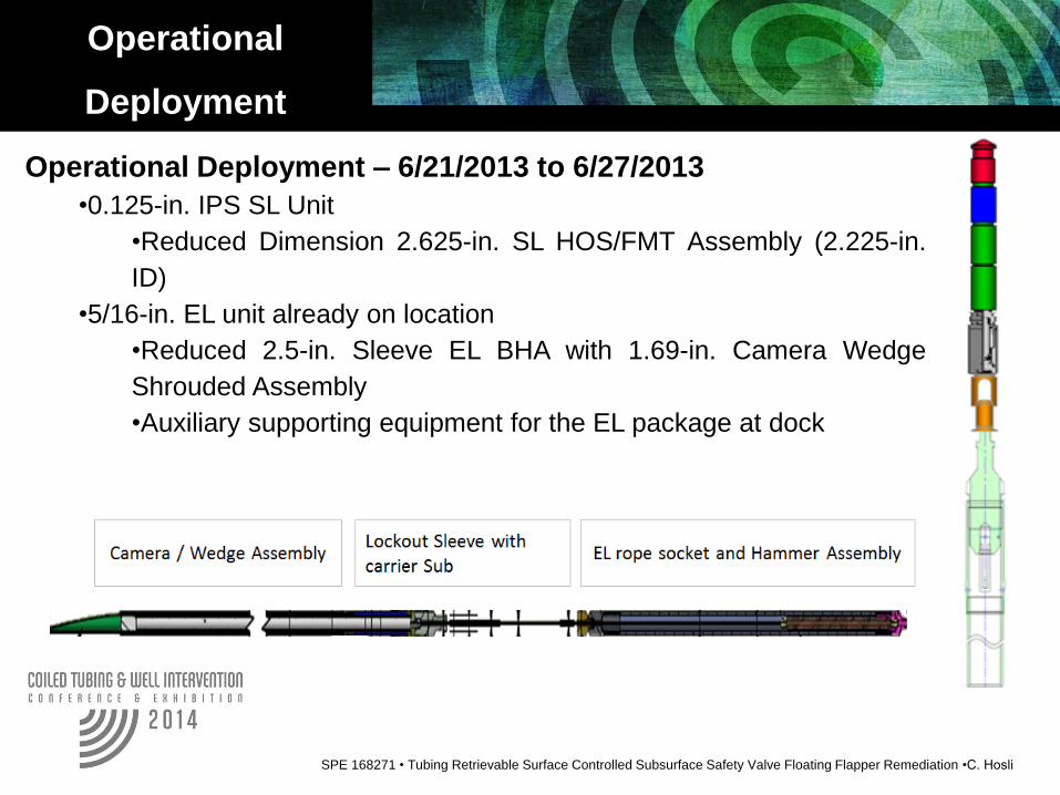
Operational Deployment – 6/21/2013 to 6/27/2013
•0.125-in. IPS SL Unit
•Reduced Dimension 2.625-in. SL HOS/FMT Assembly (2.225-in.
ID)
•5/16-in. EL unit already on location
•Reduced 2.5-in. Sleeve EL BHA with 1.69-in. Camera Wedge
Shrouded Assembly
•Auxiliary supporting equipment for the EL package at dock
SPE 168271 • Tubing Retrievable Surface Controlled Subsurface Safety Valve Floating Flapper Remediation •C. Hosli
SLIDE TITLE HERE
Slide 24
Operational
Deployment
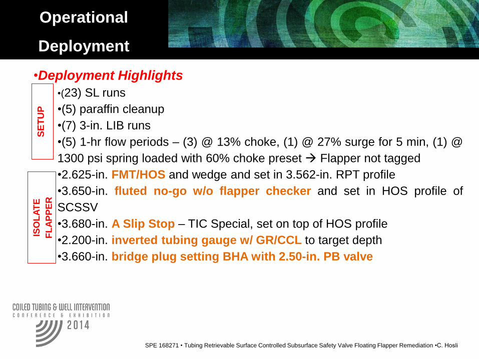
•Deployment Highlights
•(23) SL runs
•(5) paraffin cleanup
•(7) 3-in. LIB runs
•(5) 1-hr flow periods – (3) @ 13% choke, (1) @ 27% surge for 5 min, (1) @
1300 psi spring loaded with 60% choke preset Flapper not tagged
•2.625-in. FMT/HOS and wedge and set in 3.562-in. RPT profile
•3.650-in. fluted no-go w/o flapper checker and set in HOS profile of
SCSSV
•3.680-in. A Slip Stop – TIC Special, set on top of HOS profile
•2.200-in. inverted tubing gauge w/ GR/CCL to target depth
•3.660-in. bridge plug setting BHA with 2.50-in. PB valve
SPE 168271 • Tubing Retrievable Surface Controlled Subsurface Safety Valve Floating Flapper Remediation •C. Hosli
SE
TU
P
ISO
LA
TE
FL
AP
PE
R
SLIDE TITLE HERE
• Introduction
• Case History Background
• TRSCSSV Flapper Obstruction and Failed Operation
• Toolstring Development and Testing
• Operational Deployment
• Conclusions and Observations
Slide 25
Presentation
Agenda

SLIDE TITLE HERE
Slide 26
Conclusions and
Observations
• Original toolstring was all that was required for modification and
redeployment
• Three possible rigless operations
• Modeling and testing before deployment continues to shape the
best view
I. The problem of a floating flapper in this particular TRSCSSV is
especially difficult to isolate
II. Critical to match the preferred flapper orientation to the BHA
a) SL FMT/HOS BHA – Flapper Bottom Up
b) EL Camera/Wedge/HOS/Shear Sub BHA – Flapper Bottom
Up
c) EL Milling/Skirt BHA - Flapper Top Up
III. Depending on production characteristics, a “hard” short surge
might be required to flip a flapper if not in the required orientation
IV. Ensuring accurate flag depth and toolstring location to these
flagged depths
V. Test fixture of the exact same dimensions – if available, provides
a means to test the BHA’s before operational deployment
(in) (ft)Slips Slips for 4.5” 15.10# (Can use elevator to lift into place)
Pup Joint 4.5” 15.10# (Grade not critical, ID critical) 3.826 10.00
CouplingCoupling to mate pup joint to 4.5" joint tubing (Grade not
critical, ID critical)
3.826 (sized to mate to
tubing and pup joint) 1.00
Pup Joint4.5” 15.10# 13cr95y pup joints x 10’ long (Grade not critical,
ID critical) 3.826 10.00
Upper Restriction Upper SCSSV Assembly Restriction 3.562 1.17
SCSSV Upper Sub Top Seal Bore SCSSV 3.625 7.02
SCSSV CavityCavity of approprite length and ID as specified to mimic
cavity flapper is currently sitting. 5.945 0.40
SCSSV Lower Sub Bottom Seal Bore SCSSV 3.567 1.17
Pup Joint
4.5” 15.10# 13cr95y pup joints x 10’ long (Grade not critical,
ID critical) Holes Punched into bottom pup to allow fluid
pumped to drain but cuttings to fall down to rest on
Bottom Cap 3.826 10.00
Bottom CapCap to keep millings and parts from falling for subsequent
analysis N/A 0.50
Text Fixture
Schematic*
**Lengths for coupling, flange, and joint tubing are estimated
* Lengths in Schematic are not to scale
Length**IDDescriptionComponent

Acknowledgements / Thank You / Questions
Shell Exploration and Production Company
Halliburton Energy Services
Expro Well Intervention Services
Welltec Well Intervention Services
Slide 27