
Spatially resolved heat release rate measurements in ... · of unsteady flame behaviors such as...
16
Combustion and Flame 144 (2006) 1–16 www.elsevier.com/locate/combustflame Spatially resolved heat release rate measurements in turbulent premixed flames B.O. Ayoola a , R. Balachandran b , J.H. Frank c , E. Mastorakos b , C.F. Kaminski a,∗ a Department of Chemical Engineering, University of Cambridge, Cambridge, UK b Department of Engineering, University of Cambridge, Cambridge, UK c Combustion Research Facility, Sandia National Laboratories, USA Received 7 February 2005; received in revised form 7 June 2005; accepted 16 June 2005 Available online 19 August 2005 Abstract Heat release rate is a fundamental property of great importance for the theoretical and experimental elucidation of unsteady flame behaviors such as combustion noise, combustion instabilities, and pulsed combustion. Investiga- tions of such thermoacoustic interactions require a reliable indicator of heat release rate capable of resolving spatial structures in turbulent flames. Traditionally, heat release rate has been estimated via OH or CH radical chemilu- minescence; however, chemiluminescence suffers from being a line-of-sight technique with limited capability for resolving small-scale structures. In this paper, we report spatially resolved two-dimensional measurements of a quantity closely related to heat release rate. The diagnostic technique uses simultaneous OH and CH 2 O planar laser-induced fluorescence (PLIF), and the pixel-by-pixel product of the OH and CH 2 O PLIF signals has previ- ously been shown to correlate well with local heat release rates. Results from this diagnostic technique, which we refer to as heat release rate imaging (HR imaging), are compared with traditional OH chemiluminescence mea- surements in several flames. Studies were performed in lean premixed ethylene flames stabilized between opposed jets and with a bluff body. Correlations between bulk strain rates and local heat release rates were obtained and the effects of curvature on heat release rate were investigated. The results show that the heat release rate tends to increase with increasing negative curvature for the flames investigated for which Lewis numbers are greater than unity. This correlation becomes more pronounced as the flame gets closer to global extinction. 2005 The Combustion Institute. Published by Elsevier Inc. All rights reserved. Keywords: Heat release rate imaging; Simultaneous OH and CH 2 O PLIF; OH chemiluminescence; Turbulent premixed flames; Flame front curvature 1. Introduction Chemiluminescence measurements are widely used in estimating global heat release rates in hy- * Corresponding author. E-mail address: [email protected] (C.F. Kaminski). drocarbon flames [1]. The simplicity of the experi- mental implementation, combined with the flexibil- ity of species selectivity, makes chemiluminescence a very useful diagnostic in modern combustion re- search. Chemiluminescence is the radiative emission given off by chemically excited reactive species (de- noted by “*”) and serves as a good indicator of global heat release rate in premixed hydrocarbon flames. The 0010-2180/$ – see front matter 2005 The Combustion Institute. Published by Elsevier Inc. All rights reserved. doi:10.1016/j.combustflame.2005.06.005
Transcript of Spatially resolved heat release rate measurements in ... · of unsteady flame behaviors such as...

e
cidationnvestiga-g spatial
chemilu-ility for
ents of a
-hich wece mea-n opposedined andte tends toater than
es;
Combustion and Flame 144 (2006) 1–16www.elsevier.com/locate/combustflam
Spatially resolved heat release rate measurementsin turbulent premixed flames
B.O. Ayoolaa, R. Balachandranb, J.H. Frankc, E. Mastorakosb,C.F. Kaminskia,∗
a Department of Chemical Engineering, University of Cambridge, Cambridge, UKb Department of Engineering, University of Cambridge, Cambridge, UK
c Combustion Research Facility, Sandia National Laboratories, USA
Received 7 February 2005; received in revised form 7 June 2005; accepted 16 June 2005
Available online 19 August 2005
Abstract
Heat release rate is a fundamental property of great importance for the theoretical and experimental eluof unsteady flame behaviors such as combustion noise, combustion instabilities, and pulsed combustion. Itions of such thermoacoustic interactions require a reliable indicator of heat release rate capable of resolvinstructures in turbulent flames. Traditionally, heat release rate has been estimated via OH or CH radicalminescence; however, chemiluminescence suffers from being a line-of-sight technique with limited capabresolving small-scale structures. In this paper, we report spatially resolved two-dimensional measuremquantity closely related to heat release rate. The diagnostic technique uses simultaneous OH and CH2O planarlaser-induced fluorescence (PLIF), and the pixel-by-pixel product of the OH and CH2O PLIF signals has previously been shown to correlate well with local heat release rates. Results from this diagnostic technique, wrefer to as heat release rate imaging (HR imaging), are compared with traditional OH chemiluminescensurements in several flames. Studies were performed in lean premixed ethylene flames stabilized betweejets and with a bluff body. Correlations between bulk strain rates and local heat release rates were obtathe effects of curvature on heat release rate were investigated. The results show that the heat release raincrease with increasing negative curvature for the flames investigated for which Lewis numbers are greunity. This correlation becomes more pronounced as the flame gets closer to global extinction. 2005 The Combustion Institute. Published by Elsevier Inc. All rights reserved.
Keywords:Heat release rate imaging; Simultaneous OH and CH2O PLIF; OH chemiluminescence; Turbulent premixed flamFlame front curvature
elyhy-
-il-ncere-sione-alThe
1. Introduction
Chemiluminescence measurements are widused in estimating global heat release rates in
* Corresponding author.E-mail address:[email protected](C.F. Kaminski).
0010-2180/$ – see front matter 2005 The Combustion Institutdoi:10.1016/j.combustflame.2005.06.005
drocarbon flames[1]. The simplicity of the experimental implementation, combined with the flexibity of species selectivity, makes chemiluminescea very useful diagnostic in modern combustionsearch. Chemiluminescence is the radiative emisgiven off by chemically excited reactive species (dnoted by “*”) and serves as a good indicator of globheat release rate in premixed hydrocarbon flames.
e. Published by Elsevier Inc. All rights reserved.

2 B.O. Ayoola et al. / Combustion and Flame 144 (2006) 1–16
in-ceenus-
te in
ofse
stor.sid-
e-s-eatencens
res,nd
dyIF)
e isserpre-queels
ex-usingr-ofrboni-auseth-one, ac-
e-tstly
heure--ld,p-
andor-picde-
ae
esof
cor-fromsing
re-OH
e-des.
edpa-sndentsowd,bi-ut
lt ofsesav-ceddyasthatrs.
er-re-by
onsrateres-to
t theayions
cefor
hetheandfol-
ff-e,aseh
va-sti-
intensity of the chemiluminescent radiation varies learly with fuel flow rate at a constant equivalenratio [2]. As a result, chemiluminescence has beextensively used to study different unsteady combtion phenomena. Haber et al.[3] used OH* and CH*
to develop a measure of unsteady heat release raa laminar Bunsen flame. Lieuwen and Neumeier[4]and Bloxsidge et al.[5] have reported on the useCH* to obtain transfer functions relating heat releaand pressure fluctuations in an unsteady combuOther chemiluminescent species have been conered as indicators of heat release, such as C2 and CO2[6,7]. However, chemiluminescence suffers from bing a line-of-sight technique with limited spatial reolution; hence, small-scale structures and local hrelease rates cannot be resolved. Chemiluminescis inadequate for studying the detailed interactiobetween reaction layers and turbulent flow structuwhich can result in localized variations in strain aheat loss, as well as extinction.
In order to resolve spatial structures in unsteacombustion, planar laser-induced fluorescence (PLmethods are often employed. Here, fluorescenccaptured from the intersection volume of a thin lasheet in a flame, and small-scale structures areserved in the resulting signal images. The techniis species-selective and sensitive, with signal levproportional to the relative concentrations of thecited species. One species that has been imagedPLIF is the formyl radical (HCO), which has the paticular advantage of being an excellent indicatorheat release rate in steady and unsteady hydrocaflames[7]. The production rate of the formyl radcal provides a good measure of heat release becHCO is the final step along one of the major paways to the production of CO, and a large fractiof reactions proceed along this route. Furthermorsignificant source of HCO production involves reations with CH2O, and CH2O is in turn produced byone of the main heat release reactions, CH3 + O →CH2O + H. Since the removal rate of the highly ractive formyl radical is significantly faster than iproduction rate, the HCO concentration is direcproportional to its production rate[7]. As a result,the HCO concentration correlates directly with theat release rate. However, the direct PLIF measment of HCO is very difficult due to its short fluorescence lifetime, low fluorescence quantum yieand relatively low concentrations. An alternative aproach uses the product of simultaneous OHCH2O PLIF measurements to obtain a signal that crelates with HCO production rate. The spectroscomethodology of this imaging technique has beenscribed and demonstrated by Paul and Najm[8] in aN2-diluted premixed laminar V-flame perturbed byvortex. Vagelopoulos and Frank[9] demonstrated th
technique in undiluted premixed counterflow flamfor rich and lean equivalence ratios with a rangestrain rates. Both of these studies reported goodrelations between heat release rates predictedlaminar flame calculations and those measured uOH and CH2O PLIF images. Fayoux et al.[10] alsoreport good correlations between their numericalsults and heat release rate profiles measured usingand CH2O PLIF images in a laminar counterflow prmixed flame. Böckle et al.[11] have also performedemonstration experiments in premixed swirl flam
In this paper, we present simultaneous OH/CH2OPLIF measurements in turbulent lean premixflames. We compare temporally resolved and stially averaged HR results with OH* measurementand investigate the effects of bulk strain rates aflame curvature on the heat release rates. Experimwere performed in a turbulent premixed counterflflame, in which bulk strain rates could be varieand also in an acoustically forced bluff-body stalized flame, which could be operated with and withoswirl. Observed flame perturbations were the resuinlet velocity fluctuations, turbulence and swirl. Theinfractions on the flame front typify the conditionin industrial combustors subject to unsteady behiors such as combustion noise, combustion induinstabilities and pulsed combustion. The bluff-bostabilized combustor investigated in this work wdesigned to simulate the instability phenomenonoccurs in industrial lean premixed (LP) combustoThese instabilities result from constructive interfence between inlet velocity fluctuations and heatleased from the flame, and they can be initiatedsmall variations in equivalence ratio. These variaticause corresponding fluctuations in heat releaseand consequently in gas density. The associated psure fluctuations in the LP combustor can couplean acoustic resonance in the combustor such thaamplitude of instabilities can either grow or decdepending on the phase of the pressure fluctuatwith respect to the heat release fluctuations[4,12].The current work is part of a wider effort to enhanour understanding of and predictive capabilitiesthese phenomena[13,14].
The outline of the paper is as follows. First, timplementation of the imaging technique andprocess of analyzing the heat release imageschemiluminescence images are discussed. This islowed with a presentation of results from the blubody stabilized flame and from the counterflow flamwith an emphasis on the comparison of heat relerates obtained with OH* chemiluminescence and witthe simultaneous OH and CH2O PLIF imaging tech-nique. The correlation of heat release rate with curture is then presented for the different flames invegated.

B.O. Ayoola et al. / Combustion and Flame 144 (2006) 1–16 3
un-COase
pre-lsod-re-by
al-gesisi-
eatOH
hec-
dre
on
ndl-
de--
Fse-d of
nsag-de-
gly
enald
de-
s at
OH
od-hattem-l, andi-
thetheo
e ishe
lapR
the-d
then-
of-
ela-
eenes.nd-tity
2. Experimental methods
2.1. Heat release rate imaging
In recent computational studies of steady andsteady hydrocarbon flames, the concentration of Hhas been found to correlate well with heat relerate[7]. However, HCO is difficult to image with LIFbecause its accessible electronic transitions aredissociative[15]. The fluorescence signals are astrongly quenched, all resulting in very short excitestate lifetimes. In spite of these difficulties, measuments of HCO concentrations have been madeseveral researchers including Jeffries et al.[16] andNajm et al.[7]. The latter group reported peak signto-noise ratios of less than 2:1 on 100-shot averaof HCO PLIF images. As a result, the techniqueonly applicable in steady or periodically forced lamnar flames but probably not in turbulent flames.
An alternative technique for measuring local hrelease rates uses simultaneous PLIF images ofand CH2O [8,9]. These two species react to form tmajority of HCO in hydrocarbon flames via the reation
CH2O + OH → HCO+ H2O. (1)
The forward rate of this reaction isk(T )[CH2O][OH],wherek is the rate constant,T is temperature, an“[ ]” denote number densities. The LIF signals arelated to species densities with a dependencethe local composition and temperatureT that resultsfrom variations in the collisional quenching rates aBoltzmann population fraction. The product of simutaneously recorded LIF signals of CH2O and OH cantherefore be expressed as
(CH2O LIF)(OH LIF) = f (T )[CH2O][OH], (2)
wheref (T ) represents the combined temperaturependence of the CH2O and OH LIF signals. At a constantφ, and over a limited range ofT , it is possibleto select transition lines such thatf (T ) is propor-tional to the forward rate constantk(T ) of the reactionin Eq. (1) [8]. As a result, the product of the LIsignals is proportional to the reaction rate. Welected overlapping transitions near the bandheathe A1A2–X1A141
0 system near 353 nm for CH2O
and theQ1(6) transition in theA2Σ+–X2Π(1,0)
band near 283 nm for OH. Numerical simulatiowere used to test the validity of the reaction rate iming scheme for these transitions. The temperaturependences ofk(T ) and f (T ) were computed usinresults of a laminar flame calculation for a freepropagating lean (φ = 0.6) ethylene/air flame.Fig. 1showsk(T ) andf (T ) normalized by the respectivvalues at 1350 K. The rate constant is proportioto T 0.89exp(−204.5/T ) [19]. The temperature- an
Fig. 1. Calculated profiles of the rate constant,k(T ), andf (T ), the combined temperature dependence of the CH2Oand OH-LIF signals assuming two different temperaturependencies of the quenching cross sections for CH2O LIF.The curves are normalized by their respective valueT = 1350 K.
species-dependent quenching cross sections forare reported in the literature[20,21], but detailedquenching data are currently not available for CH2O.For the simulations, we assume two simplistic mels of CH2O quenching. The first model assumes tquenching cross sections are constant across theperature range of interest. In the second mode1/
√T dependence is assumed. The simulations i
cate a good correlation betweenk(T ) andf (T ) fortemperatures between 900 and 1500 K, which istemperature range of significant overlap betweenCH2O and OH concentration profiles. For the twCH2O quenching models considered here, therlittle sensitivity to the functional dependence of tquenching cross sections onT . The relatively nar-row range of temperatures in the region of overfor CH2O and OH reduces the sensitivity of the Hdiagnostic to variations inf (T ). Further simulationsin ethylene/air flames indicate that the product ofCH2O-LIF and OH-LIF signals is primarily dependent on the CH2O and OH concentration profiles anis only moderately sensitive to variations inf (T ).The results of our simulations add confidence tovalidity of the technique, which was initially demostrated in rich N2-diluted methane flames[7]. We ex-pect the technique to be valid for a wide rangestrain rates. Law et al.[22] investigated planar premixed hydrocarbon flames with Lewis number Le> 1and reported that flame temperature profiles are rtively insensitive to variations in strain rate.
In this paper, the HR imaging technique has bused to investigate fully premixed ethylene/air flamA similar methodology was employed by Rehm aPaul[17] and Frank et al.[18], who used simultaneous CO and OH PLIF imaging to determine a quan

4 B.O. Ayoola et al. / Combustion and Flame 144 (2006) 1–16
ion
enex-aseeston
and
ea-
nthed
yers,andemi-at rel be
thenttsve-ve
ymo-odel
ownce
woded
rtedcitym-osart
owop-e
tohe
di-thee on
d
dm-edesa-woach
that is proportional to the forward rate of the reactCO+ OH → CO2 + H.
2.2. OH chemiluminescence imaging
Chemiluminescence is radiative emission givoff by chemically excited reactive species and istensively used as an indicator of global heat relerate in premixed hydrocarbon flames. The strongchemiluminescence emitters in lean hydrocarbcombustion are OH* , CH* , and CO*
2, and all havebeen used as indicators of global heat release ratetheir relative merits discussed[6]. For OH* , whichwas used in the present study, the peak of theA2Σ
emission occurs at 310± 10 nm; hence, OH* can becollected using UV-sensitive CCD cameras. Our msurements of OH* include a small contribution fromCO*
2 (∼10%) because CO*2 has a broadband emissiospectrum extending from 350 to 600 nm; however,effect of this on OH* signals is significantly reduceby the narrow-band collection of the OH* chemilu-minescence signals.
2.3. Burners
Heat release rate measurements using OH, CH2O,and OH* were made in counterflow and bluff-bodstabilized flames. This section describes the burnflame configurations, and diagnostic apparatusthe process of analyzing the fluorescence and chluminescence images. In subsequent sections, helease rates measured with the PLIF technique wildenoted by “HR.”
2.3.1. Counterflow combustorCounterflow flames are used extensively in
verification and development of models for turbulereacting flows[23,24]. Experimental measuremenand computation of flow-field properties such aslocity and strain and their effect on the flame habeen performed by a number of researchers[24–28].Lindstedt et al.[25] used particle image velocimetrto determine planar strain rates and employedment closure and Reynolds stress closure to msuch flames numerically. Measurements of OH* andCH* have also been made in natural gas counterflflames for the development of a chemiluminescesensor as a measure of equivalence ratio[28].
The combustor used in this work consisted of t25-mm-diameter opposing nozzles, each surrounby a concentric tube for an external co-flow of N2.Flow straighteners and turbulence grids were inseinto the nozzles to ensure that the turbulent veloprofiles across the outlets were uniform; the cobustor is similar to that described by Mastoraket al. [26]. The nozzles were mounted 35 mm ap
-
Fig. 2. Schematic of the counterflow combustor.
and fuel and air supplied using calibrated mass flcontrollers. The flame was stabilized betweenposed jets of premixed C2H4 and air at the samequivalence ratios, ranging from 0.5 to 0.7 (Le> 1).Bulk flow velocities were between 2 and 4 m/s. Thelatter condition resulted in flames burning closethe extinction limit. A schematic representation of tcounterflow combustor is shown inFig. 2. Both HRand OH* measurements were taken for these contions, with the emphasis on the investigation ofeffects of the heat release rate and flame structurincreasing bulk strain rates,Sb, defined as
(3)Sb = 2Ub
2D,
whereUb is the bulk velocity from each nozzle an2D is the separation between the two nozzles[28].
2.3.2. Bluff-body combustorThe 10-kW laboratory-scale bluff-body stabilize
combustor was designed to model instability phenoena of the type that occur in industrial lean premix(LP) combustors. In order to mimic such instabilitiin a simple, well-controlled system, velocity fluctutions were imposed on the bluff-body flame using tacoustic drivers mounted diametrically opposite eother on the circumference of the burner plenum[13].Measurements of HR and OH* were carried out withthe combustor operating on premixed C2H4 and air at

B.O. Ayoola et al. / Combustion and Flame 144 (2006) 1–16 5
m-
es
heresep-
weree
sti-0.6aulks
4balith-cebal
),gh-ionfit-ed
or)ec-
IFlednm
onding
µmo-calereve-lessntssnot
tra-tion
woure-
ievefor
H
eenoci-up,ren-
Fig. 3. Schematic of the enclosed bluff-body stabilized cobustor.
Table 1Summary of the operating conditions for the different flaminvestigated in the bluff-body stabilized ethylene flames
Flameno.
Forcingfreq., Hz
φ Swirlno.
Axialvel., m/s
Reynoldsno., Re
Flame 1 0 0.60 0 9.7 19,000Flame 2 160 0.60 0 9.7 19,000Flame 3 0 0.45 0 15.7 29,000Flame 4 0 0.45 0.7 9.7 19,000
equivalence ratios between 0.5 and 0.7 (Le> 1). Theflame is enclosed in a quartz tube to ensure that tis no recirculation of fresh air, which would caulocal variations in equivalence ratio. A schematic reresentation of the combustor is shown inFig. 3.
In this paper, heat release rate measurementsmade for four different bluff-body stabilized flamconfigurations described inTable 1. In the table,flame 1 and flame 2 refer to unforced and acoucally forced flames both at an equivalence ratio ofand a bulk velocity of 9.7 m/s. Flame 3 describesleaner flame at an equivalence ratio of 0.45 and a bvelocity of 15.6 m/s, while flame 4 also describea leaner flame at a bulk velocity of 9.7 m/s and ageometric swirl number of 0.7; flame 3 and flameboth describe flame conditions very close to gloextinction. Measurements were made with and wout swirl to investigate the effect of high turbulengenerated by the swirl with the flame close to gloextinction.
Fig. 4. Schematic of the laser imaging facility.
2.4. Diagnostic apparatus
The laser system for imaging OH and CH2O con-sisted of two Nd:YAG lasers (Continuum Surelitetwo dye lasers (Sirah Cobra-Stretch), and two hiresolution double-exposure ICCD cameras (LavisNanostar). The camera for imaging OH PLIF wasted with a UV f/4.5 camera lens (Nikkor) equippwith UG 11 and WG 305 filters (Comar). The CH2Ocamera was fitted with an f/1.2 camera lens (Nikkand GG 375 and SP 550 filters (Comar). For sptral identification of OH and CH2O transitions, LIFexcitation scans were performed prior to the PLmeasurements. For OH LIF, the frequency-douboutput from one dye laser was tuned near 283to excite theQ1(6) line in the A2Σ+–X2Π(1,0)
band. The frequency-doubled output from the secdye laser was tuned to pump the peak of overlapptransitions in theA1A2–X1A141
0 band of CH2O near
353.17 nm. The laser beams (linewidth of 0.12 cm−1)were expanded into sheets 50 mm high and 100thick, using cylindrical planoconvex lenses with fcal lengths of 25 mm and spherical lenses with folengths of 250 mm. Pulse energies of 15 mJ wavailable from the dye lasers at the different walengths, but the beams were spatially filtered andthan 5 mJ was used for the OH PLIF measuremeand 12 mJ for the CH2O measurements. This wadone to ensure that the fluorescence signals weresaturated and linearly proportional to the concentions of probed species. A schematic representaof the setup is shown inFig. 4.
The ICCDs were each capable of acquiring timages in rapid succession. This enabled the measment of OH PLIF shortly followed by an OH* emis-sion measurement on the same camera. To achthis, the camera intensifiers were gated to open350 ns for the PLIF measurements and 50 µs for O* .A delay of 500 ns was set between the CH2O and OHlaser pulses to avoid potential interferences betwthe laser pulses and cameras. At the given bulk velties and with the spatial resolution of the optical setthe chosen delay of 500 ns between the pulses

6 B.O. Ayoola et al. / Combustion and Flame 144 (2006) 1–16
ous
foreasein
thecor-one
ers.uredaporrtht isbe-ersed
ern)theec-on
im-redref-a-asthe
inheenat
es-e.e
ch-de-or-mtric
.esas
nal.on
istheasceas-mis
a-iqueandpro-erntslue.Hitiesde-te-did
n-erecer-am
ro-vi-er-tions,orly
er in
asfed
ionom
on-e
dered the PLIF measurements virtually instantaneon flow timescales.
2.5. Image analysis
2.5.1. Fluorescence image analysisThe raw PLIF images were postprocessed be
product images were calculated to obtain heat releinformation. First, a background image, measuredthe absence of the flame, was subtracted fromfluorescence images. Second, the images wererected for laser sheet inhomogeneities. This was dby dividing the instantaneous OH and CH2O imagesby the average beam profiles of the exciting lasThe beam profiles for each dye laser were measprior to flame measurements in a homogeneous vof air-diluted biacetyl (for CH2O) and acetone (foOH). Finally, both PLIF images were aligned wieach other on a pixel-by-pixel basis. The alignmencrucial to the success of this imaging techniquecause of the small spatial scales of reacting layin the flame. This alignment process was performin several stages. First, a target image (grid pattwas aligned in the measurement plane, defined bylaser sheets and in the view of both cameras. Sond, the coordinates of several reference pointsthe target image, captured by the CH2O camera, wererecorded as anchor points. The target was thenaged with the OH camera. The image was mirroand the corresponding coordinates of the sameerence points were identified. Third, a transformtion matrix relating the two sets of coordinates wcalculated and used to map the OH images intocoordinate system of the CH2O image. This imageprocessing technique is similar to that employedparticle image velocimetry and its precision is in tsubpixel range[29]. The corrected images were thmultiplied on a pixel-by-pixel basis to obtain the herelease rate images.
Both cameras had an ICCD chip size of 1280×1024 pixels and were positioned to give a spatial rolution of 0.07 mm/pixel at the measurement planAt this high resolution, the spatial distribution of thspecies being probed is clearly resolved.
2.5.2. Chemiluminescence image analysisSince chemiluminescence is a line-of-sight te
nique, the averaged OH* images were deconvolveinto a 2-D projection for comparison with the HR rsults; this deconvolution was performed using the fward Abel transform. The Abel transform algorithreconstructs an axial projection of an axisymmefunction according to the equation
(4)f (r) = − 1
π
R∫g′(x)dx√x2 − r2
,
r
whereg′(x) is the line-of-sight integrated OH* sig-nal andf (r) is its forward Abel transform projectionWalsh et al.[30] have reported that the peak valuof Abel inverted signals can be underestimated bymuch as 30%, depending on the location of the sigAt the base of the bluff body, where the distributiis thinnest, the peak of the Abel inverted OH* sig-nal may be underestimated relative to the OH* signalfurthest from the bluff body, where the distributionbroader. In our case, the collection solid angle forOH* optics is 0.04 radians and the depth of field wgreater than the width of the bluff-body flame. Sinthe collection angle is small enough to permit thesumption of parallel rays, the error introduced frodiffuse signals collected outside the depth of fieldminimized.
2.6. Uncertainty estimates
The major contributors to uncertainty in the mesurement of heat release rate using the HR technare the shot-to-shot variation of the laser energythe subtle changes that occur in the laser beamfiles. The maximum deviation in energy of both laspulses during the period of taking PLIF measuremehas been estimated to be 15% of its mean vaSpatially integrated measurements of HR and O*
were evaluated by summing the measured quantover the entire imaged region, and the standardviation for a 75-shot average of these spatially ingrated quantities was 20%. The laser-beam profilenot vary significantly during the acquisition of 75 istantaneous images; therefore, the PLIF images wcorrected by the average beam profiles, and the untainty introduced as a result of variations in the beprofiles was negligible.
Additional systematic uncertainties may be intduced by variations in the local LIF quenching enronment. The evaluation of this error requires tempature and species dependent quenching cross secwhich are available for OH but are quite limited fCH2O. However, we expect this error to be relativemodest, based on the simulations discussed earliSection2.1.
3. Results and discussion
Chemiluminescence from flame species suchOH, CH, and CO2 are widely used indicators oglobal heat release rate in the study of premixflames. The initial focus of the present investigatwas on the comparison of global HR estimates frthe HR technique and the OH* imaging. Followingthis comparison, we used the HR method that, in ctrast to OH* , is capable of resolving detailed flam

B.O. Ayoola et al. / Combustion and Flame 144 (2006) 1–16 7
ulkf the
Fig. 5. (a) Instantaneous OH PLIF, CH2O PLIF, and corresponding HR and OH* images taken in a counterflow flame at a bvelocity of 2.9 m/s (Sb = 82 s−1) with φ = 0.55. The line across the flame front on the HR image indicates the position oprofiles displayed inFig. 6. (b) An average of 75 images taken at the same bulk velocity.
alent
ndp-to
atesre
bysta-the
ia-tstw
n of
Rea-gushity
esas
Hthe
olfea-
e in
nted
resw-insratein,m
eninH,t at
, then,
structural information, to obtain correlations of locheat release rate and curvature. These measuremwere performed both for the counterflow flame afor the bluff-body stabilized flame under different oerating conditions. Since an aim of this paper iscompare the spatial distribution of heat release robtained by HR with OH* , the results presented wenormalized by their mean values.
3.1. Comparison of OH* and HR
3.1.1. Counterflow flameThe dynamics of the counterflow combustor,
which one-dimensional flames (in the mean) arebilized in opposed streams of reactants, enableinvestigation of bulk strain rate effects by the vartion of bulk flow rate (Eq.(3)). Hence, measuremenof heat release rate with HR and OH* were taken adifferent bulk flow rates in the premixed counterfloflame.
Fig. 5 displays simultaneous OH* , OH PLIF, andCH2O PLIF measurements from the shaded regioschematic diagram shown inFig. 2. The pixel size was0.07 mm/pixel on all measurements shown. All Himages were evaluated from single-shot PLIF msurements of OH and CH2O before any averaginwas performed.Fig. 5a shows a set of instantaneoOH PLIF, CH2O PLIF, and OH* measurements witthe corresponding HR image taken at a bulk velocof 2.9 m/s. Fig. 5b shows an average of 75 imagfor the same conditions. The Abel reconstruction wnot performed on the average OH* image shown inFig. 5b.
The OH PLIF image shows the distribution of Oradicals in the confined postflame region betweentwo flames. An isolated packed of CH2O is observedin the preheat region of the flame, indicative of cotemperature chemistry. There is no corresponding
s
Fig. 6. Normalized profiles of OH, CH2O, and HR takenacross the flame along the line indicated on the HR imagFig. 5a.
ture in the OH PLIF image, and thus no significaheat release is taking place. Formaldehyde is formin the preheat region at relatively low temperatu(1000 K) because it is central to alternative lotemperature chemical pathways of fuel oxidationlean hydrocarbon flames[31]. From the instantaneouHR images, we observe that the heat releasevaries along the flame front as it is affected by stracurvature, and turbulence. The flame front is 0.5 mthick as it is marked by the region of overlap betweOH and CH2O radicals. This can clearly be seenFig. 6, which shows instantaneous profiles of OCH2O, and HR across the instantaneous flame fronthe position marked on the HR image shown inFig. 5.
From the averaged heat release rate imagesspatial average,Qav (average intensity of all pixels ithe image), for HR and OH* was evaluated as follows
(5)Qav =∑
Ix,y
n,
whereIx,y is the intensity at every pixel andn is thenumber of pixels.Fig. 7 shows the variation ofQav

8 B.O. Ayoola et al. / Combustion and Flame 144 (2006) 1–16
)
ofi-aserted
on-
ntsh a
a-lly
phe-ion.ateof
thea-
e 1sota-vedelye, italsst-HRu-agerush
Fig. 7. Normalized profiles of HR and OH* with increasingbulk strain rate,Sb.
for HR and OH* (20% uncertainty in both quantitieswith increasing bulk strain,Sb (Qav is the averageover all bulk strain rates). The normalized profilesHR and OH* in the counterflow flame seem to indcate similar trends of slightly decreasing heat relerates with increasing bulk strain as was also repoby Hardalupas et al.[28]. However, with the stateduncertainties our measurements do not provide cclusive evidence for this trend.Fig. 8 shows instan-taneous images of OH, CH2O, HR, and OH* . Theimages show that the upper and lower flame fromerged at the edge of an extinguished region witbulk strain rate of 100 s−1. A similar phenomenon
was predicted by Bray et al.[32] and observed byIshizuka and Law[33] and Luff et al.[34] in theirstudy of premixed counterflow flames. This is a mjor advantage of using HR, as it captures spatiaresolved heat release rate structures of localizednomena such as flame merging and local extinctA discussion of the fluctuations of heat release ralong the flame will be presented in a later sectionthis paper.
3.1.2. Bluff-body stabilized flameSimilar measurements were performed in
bluff-body stabilized flame over a range of equivlence ratios.Fig. 9corresponds to flame 1 inTable 1,which is unforced (no external excitation).Fig. 9ashows a set of instantaneous andFig. 9b shows av-eraged images of OH PLIF, CH2O PLIF, and OH*
and the corresponding HR images taken in flamat φ = 0.6. The region of the flame imaged is alshown. In the top right-hand corner of the instanneous OH PLIF image, OH radicals can be obseron the outer side of the shear layer. Since relativlow signals of heat release rate are obtained hercan be concluded that the majority of the OH radicobserved are a result of the recirculation of the pocombustion gases. By comparing the averagedand OH* images, we also observe different distribtions of heat release rates. The averaged HR imshows heat release rates confined to a narrow b
dy
Fig. 8. Image of HR atUb = 3.4 m/s and a bulk strain rate of 100 s−1 with the twin flames merged.
Fig. 9. (a) Images of OH PLIF, CH2O PLIF, and corresponding HR and OH* images taken in the enclosed, unforced bluff-bostabilized flame atφ = 0.6. (b) Averaged OH PLIF, CH2O PLIF, HR, and OH* . The region imaged is also shown.

B.O. Ayoola et al. / Combustion and Flame 144 (2006) 1–16 9
sultes
ltioss-
, thero-sra-esere, thean
ses.
edr-
in-there.
yinstsatelyain
in-tedet
thes a
ec-Ramce
ro-ndc-si-ns,ea-and
Fig. 10. Profiles of normalized HR and OH* in a bluff-bodystabilized flame at different equivalence ratios.
around the flame front, while the averaged OH* im-age shows a much broader distribution. This is a reof the unrestricted OH* chemiluminescence specigiving signals from all around the flame.
The trend ofQav normalized with the overalmean of heat release rates (for all equivalence raconsidered),Qav, with increasing equivalence ratiois shown inFig. 10. The maximum equivalence ratio investigated was 0.65 because at higher valuesflame flashes back at the given bulk velocity. The pfiles in Fig. 10 both show similar increasing trendin heat release rate with increasing equivalencetio. The flow close to the exit probably experienchigher strain rates than further downstream, whthe turbulence length-scales increase. As a resultflame brush downstream of the jet exit is thicker ththe flame brush close to the jet exit[35]. We inves-tigated the HR and OH* response in different partof the flame by determining locally averaged valuThe calculations presented inFig. 10were performedin two distinct regions of the flame front as indicatin Fig. 11a.Qav was calculated for the flame at diffeent equivalence ratios in section 1 (40×8 mm), 5 mmabove the bluff body, and in section 2 (40× 8 mm),21 mm from the bluff body. The results are shownFigs. 11b and 11c. The profiles of HR exhibit similar trends, while there are differences betweenOH* profiles. There are two points of interest heFirst, HR shows the same dependence onφ for bothregions of the flame. Second, OH* rises less steeplwith φ in section 1 (close to the bluff body) thansection 2 (further from the bluff body). This suggethat HR measures heat release rates more accurthan OH* , which seems to be more sensitive to strand turbulence. Samaniego et al.[6] caution that OH*
emission from turbulent flames should be carefullyterpreted, as chemiluminescence is strongly affecby variations in strain rate and curvature. Najmal. [7] suggest that this is due to subtle shifts inreaction pathways of hydrocarbon combustion a
(a)
(b)
(c)
Fig. 11. (a) Schematic showing section 1 (lower) and stion 2 (upper), all units in mm. (b) Profile of normalized Hclose to the bluff-body (section 1) and further downstrefrom the bluff-body (section 2) with increasing equivalenratios. (c) OH* of the same quantities.
result of unsteady strain rate. Conversely, the pfile of HR supports the conclusions made by Lee aChung[23], who find that the temperature and struture of a freely propagating premixed flame is insentive to strain rate variations. From these observatiowe are led to the conclusion that HR is a good msure of heat release rate (both spatially resolved

10 B.O. Ayoola et al. / Combustion and Flame 144 (2006) 1–16
theated
va-oredoesent
ureHRta-m-be
ive
esHRnte-uchnttedt re-
lu-rates
rate,g
ed
a-les-rontr ofn-atethsHR
is-isver-thein3
sti-t onnc-nd
de,ac-
d astion
n-.9,
ro-he
for
atHRrre-ly
rre-tiveposi-e
(a)
(b)
Fig. 12. (a) Schematic showing some normals alongflame front along which heat release rates were integrand (b) definition of curvature.
global) in premixed turbulent flames. These obsertions indicate that the HR technique provides a mself-consistent measure of heat release rate thanOH* chemiluminescence in these premixed turbulflames.
3.2. Effect of curvature on heat release rate
The variation of heat release rate with curvatwas investigated using the images obtained fromin both the counterflow flame and the bluff-body sbilized flame. Such data are significant to the coputational modeling of combustion because it canused directly for the development of turbulent reactflow models[36].
In order to obtain such correlations, the HR imagwere processed in two stages. First, intensities ofimages were integrated across the flame front by igrating the profile of the local heat release rates (sas inFig. 6) along a line normal to the flame tangeat every point along the flame front. These integravalues of heat release rate data were used in healease/curvature correlations.Fig. 12a shows a typicaflame front from the counterflow flame, with evalated flame normals across which the heat releasewere thus integrated. Second, the coordinates(x, y)
of each point along the identified heat releasecontour were evaluated with respect to an origins
(also shown inFig. 12a), taken to be the point alonthe contour at whichx = 0. With (x, y, s), the curva-ture,H , at every point on the flame front is calculatusing[37,38]
(6)H =[(
d2x
ds2
)2+
(d2y
ds2
)2]1/2
mm−1.
The choice of differential width size (ds) is crucial forthe calculation of curvature. In order to obtain curvtures from both small-scale and large-scale wrinkalong the flame, the value of ds used was the average crossing length of the instantaneous flame fwith the heat release rate progress variable contou0.5. The c contour was obtained by making a cotour plot of an average of binary heat release rimages (0 is unburnt and 1 is burnt). Crossing lengare then obtained by superimposing instantaneousimages overc = 0.5 and calculating the average dtance along the flame front for which the contourcrossed by the instantaneous flame contour. The aage crossing lengths thus obtained are 7 mm forcounterflow flame, 5 mm for flame 1 and flame 2the bluff-body stabilized flame, and 4 mm for flameand flame 4. These values are inserted into Eq.(6)and H is calculated. Crossing lengths are a statical characteristic of any flame and are dependenthe degree of flame wrinkling; hence, they are a fution of turbulence and are important in the study amodeling of turbulent combustion[39,40].
With the radius of curvature on the reactant sipositive curvature was defined as convex to the retants; conversely, negative curvature was defineconcave to the reactants. A schematic representaof this convention is shown inFig. 12b.
3.2.1. Counterflow flameThe pdf of curvature for the counterflow flame, a
alyzed for 75 HR images at bulk velocities of 2.4, 2and 3.4 m/s, is shown inFig. 13a. The profile shows amean curvature of approximately 0 with all three pfiles showing an identical spread of curvatures. Tcontour plots of the joint pdf of heat release rate,Q
(normalized with the meanQ at H = 0), and curva-ture, from the integrated HR image, are shownthe three bulk velocities inFigs. 13b–13d. The con-tours show that the majority of HR was measureda curvature close to zero with a slight increase intoward negative and positive curvatures. This colation is more evident in the profile of conditionalaveraged HR against curvature shown inFig. 14. Re-searchers have reported that the trend in this colation is for increased heat release rates at negacurvatures and decreased heat release rates attive curvatures[41–43]. The correlation could be th

B.O. Ayoola et al. / Combustion and Flame 144 (2006) 1–16 11
HR
(a) (b)
(c) (d)
Fig. 13. (a) pdf of curvature(H) at different bulk velocities in the counterflow flame and contour plots of the joint pdf ofand curvature at (b) 2.4, (c) 2.9, and (d) 3.4 m/s.
then-
inge
eat
The
nyzed
inescedngle
owns-mealsone-nthees.ar-d
Fig. 14. Average profiles of HR against curvature fordifferent bulk velocities investigated in the premixed couterflow flame.
result of an increased diffusion rate of propagatradicals such asH from the reactant-side of the flamas suggested by Echekki and Chen[41] for flameswith Lewis number Le> 1. At high velocities, thistrend is indeed captured. At low velocities, the h
release seems to increase with positive curvature.trend for this is not clear.
3.2.2. Bluff-body stabilized flameIn the bluff-body stabilized flame, the correlatio
between heat release rate and curvature is analfor all the flames described inTable 1. Fig. 15a showsa set of instantaneous OH PLIF, CH2O PLIF, andOH* with the corresponding HR image taken atflame 2 andFig. 15b shows an average of 75 imagof the same species. The flame is acoustically forat 160 Hz and the images are taken at a phase aof 55◦ relative to the forcing signal. The images shthe effects of a pair of counterrotating vortices traporting premixed reactants and wrapping the flafront. The postgas region marked with OH radicis shown in the OH PLIF image and the preheat zis marked in the CH2O PLIF image. One of the vortices is filled with CH2O, indicating the penetratioof the preheat zone into the reactant mixture asflame front, shown by HR, encircles these vorticIt is worth mentioning that the vortices are also ptially visible in the OH* images, but at much reduce

12 B.O. Ayoola et al. / Combustion and Flame 144 (2006) 1–16
dy
dy
Fig. 15. (a) Instantaneous OH PLIF and CH2O PLIF and the corresponding HR and OH* images taken in the enclosed bluff-bostabilized flame forced at 160 Hz withφ = 0.6 and axial velocity 9.7 m/s. These images were taken at a phase angle of 55◦ withrespect to the input forcing signal. (b) Phase averaged OH PLIF, CH2O PLIF, HR, and OH* .
Fig. 16. (a) Instantaneous OH PLIF and CH2O PLIF and corresponding HR and OH* images taken in the enclosed, bluff-bostabilized flame withφ = 0.45 and an axial velocity of 15.6 m/s. (b) Phase-averaged OH PLIF, CH2O PLIF, HR, and OH* .
e 3
-ce
eanising
to;
e,sis.wn
onntin
the
ismthee-memetheheturesthe
oretovesur-
clarity. Similar measurements were made in flamand the images are shown inFig. 16 (bulk velocityof 15.6 m/s, φ = 0.45). This flame has a bulk velocity much greater than that of flame 2 and henis more turbulent. These conditions are close to lblowout limits of the combustor. The flame fronthighly wrinkled and has small eddies propagatalong it; this is clearly seen in the CH2O PLIF im-age inFig. 16. At this equivalence ratio, the signalnoise ratio of the OH* images is approximately 1.5:1therefore, OH* is only visible in the averaged imagwhereas the HR still performs on a single shot baSimilar observations can be made for flame 4 shoin Fig. 17. Here, the flame is close to global extinctiand is furthermore subjected to swirl. The flame frois clearly more intermittent and wrinkled as seen
the HR image. Mixing is much more intense andflame is shorter.
The pdf of curvature for each of these flamesshown inFig. 18. The larger spread of curvatures froflame 1 to flame 2 is due to the acoustic forcing offlame. As the inlet velocity is sinusoidally varied, priodic large-scale vortices are imposed on the flafront; this results in imposed curvature on the flafront as the flame wraps around the vortex. Asbulk velocity is increased from flame 1 to flame 3, tpeak of the pdf decreases and the spread of curvaincreases. This trend continues to flame 4 whereflame is subjected to swirl. As the flame gets mturbulent and is closer to lean blowout (flame 1flame 4), the peak of the pdf decreases and motoward negative curvatures while the spread of c

B.O. Ayoola et al. / Combustion and Flame 144 (2006) 1–16 13
dyLIF,
Fig. 17. (a) Instantaneous OH PLIF and CH2O PLIF and the corresponding HR and OH* images taken in the enclosed, bluff-bostabilized flame withφ = 0.45, axial velocity of 9.7 m/s and a geometric swirl number of 0.7. (b) Phase-averaged OH PCH2O PLIF, HR, and OH* .
ta-;ex-
s ofis-
se
ithiveer-
as-uresres
c-hofses,
esc-atinc-sby
ndratent
thesed
the
aseom-ts.
ally
iag-re-inedn-
Rrainen-ra-ofea-the
Fig. 18. pdf of curvature calculated from the bluff-body sbilized flames described inTable 1. Flame 1, unforced flameflame 2, forced flame; flame 3, high velocity and close totinction; and flame 4, high swirl and close to extinction.
vatures increases. The trend of increasing widththe curvature pdf with turbulence intensity is constent with the DNS results of Gashi et al.[44].
The contour plot of the joint pdf of heat relearate and curvature for each flame is shown inFig. 19.In all the cases, the contours show higher HR wnegative curvatures, compared with HR at positcurvatures. This is clearer in the conditionally avaged profile of HR shown inFig. 20.
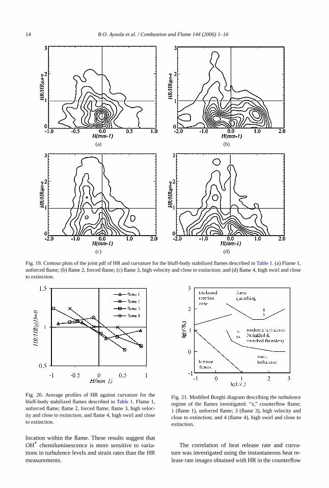
As the flame approaches extinction by increing swirl, the heat release rate at negative curvatdrops, but remains unchanged at positive curvatu(Fig. 19d, Fig. 20). The same also occurs when foring is used (Fig. 19b) and when the velocity is hig(Fig. 19c). It is evident that the expected behaviorHR, monotonically decreasing as curvature increa
is captured only for positive curvatures and for flamfar from extinction. For flames close to global extintion, it is possible that localized extinctions occurnegative curvatures. The presence of localized exttion is consistent withFig. 21, which shows the flamelocated on the modified Borghi diagram describedLipatnikov and Chomiak[45]. The unforced flame(flame 1) is subject to turbulence which wrinkles astretches the flame front and is located in the modeturbulence regime. However, in the highly turbuleflames (flame 3 and flame 4), the flame front is inflamelet quenching region, resulting in the decreaheat release rates observed inFig. 20.
4. Conclusions
The application of a diagnostic scheme usingproduct of OH and CH2O PLIF images to obtainan image that correlated with the flame heat relerate (HR) was described, and the results were cpared with OH* chemiluminescence measuremenThe HR diagnostic provides instantaneous spatiresolved measurements, while the OH* chemilumi-nescence is a line-of-sight technique. These dnostic techniques were compared in turbulent pmixed counterflow flames with different bulk strarates and in forced and unforced bluff-body stabilizflames with different equivalence ratios. In the couterflow flames, the OH* chemiluminescence and Htechniques showed similar behavior when the strate was varied. In the bluff-body flames, the depdence of OH* chemiluminescence on equivalencetio was significantly different for the two regionsthe flame brush that were considered. The HR msurements were significantly less dependent on
14 B.O. Ayoola et al. / Combustion and Flame 144 (2006) 1–16
d close
(a) (b)
(c) (d)
Fig. 19. Contour plots of the joint pdf of HR and curvature for the bluff-body stabilized flames described inTable 1. (a) Flame 1,unforced flame; (b) flame 2, forced flame; (c) flame 3, high velocity and close to extinction; and (d) flame 4, high swirl anto extinction.
the
oc-se
thatria-HR
cee;ndto
va-t re-ow
Fig. 20. Average profiles of HR against curvature forbluff-body stabilized flames described inTable 1. Flame 1,unforced flame; flame 2, forced flame; flame 3, high velity and close to extinction; and flame 4, high swirl and cloto extinction.
location within the flame. These results suggestOH* chemiluminescence is more sensitive to vations in turbulence levels and strain rates than themeasurements.
Fig. 21. Modified Borghi diagram describing the turbulenregime of the flames investigated. “x,” counterflow flam1 (flame 1), unforced flame; 3 (flame 3), high velocity aclose to extinction; and 4 (flame 4), high swirl and closeextinction.
The correlation of heat release rate and curture was investigated using the instantaneous healease rate images obtained with HR in the counterfl
B.O. Ayoola et al. / Combustion and Flame 144 (2006) 1–16 15
n-c-owndnice
eateases isusn
at-rain
heatob-eatqueamex-ives curg-
omllsEIep-
oflso
t ofofs.
re,all,
03)
.K.T-
29
id
n,
ff,
8)
30
c.
in,0)
.P.in
,T-
83–
ith,
00)
st.
e-3,n/
(3)
.B.14
st.
80–
d-
:of13-
-
t.
.P..
ine
th-
5
d.,
t.
2)
flames and from the bluff-body stabilized flames uder different operating conditions. At low bulk veloities, contour plots from the counterflow flames sha bimodal distribution with high HR at negative apositive curvatures, but the trend becomes monotoat high bulk velocities. The contour plots from thbluff-body stabilized flame show an increase in hrelease rate with negative curvatures and a decrin heat release rate with positive curvatures. Thifully consistent with our expectations from previoresults for Le> 1 flames. For flames closer to leablowout, the correlation is more pronounced, indicing that flames are more sensitive to changes in stand curvature and could also extinguish locally.
The combined OH and CH2O PLIF diagnosticprovides instantaneous measurements of relativerelease rates in turbulent premixed flames by pring a reaction rate that is highly correlated with hrelease. This spatially resolved diagnostic technienables the structural analysis of instantaneous flfronts. Although this method is technically and eperimentally demanding, it is the closest nonintrusmeasure of instantaneous heat release rates that irently available, and it is therefore a very useful dianostic tool in combustion research.
Acknowledgments
The authors acknowledge financial support frthe Cambridge Commonwealth Trust, the DTI/RoRoyce collaboration, and the EPSRC under JRGrant GR/R61994/01 and a PLATFORM grant. Walso gratefully acknowledge the support of the Hokinson Laboratory workshop at the UniversityCambridge Engineering Department. J.H. Frank aacknowledges support from the U.S. DepartmenEnergy, Office of Basic Energy Sciences, DivisionChemical Sciences, Geosciences, and Bioscience
References
[1] A.G. Gaydon, H.G. Wolfhard, Flames: Their StructuRadiation and Temperature, third ed., Chapman & HLondon, 1979.
[2] J.G. Lee, D.A. Santavicca, J. Propuls. Power 19 (20735–750.
[3] L.C. Haber, U. Vandsburger, W.R. Saunders, VKhanna, Proc. Int. Gas Turb. Inst. (2000), 2000-G0121.
[4] T. Lieuwen, Y. Neumeier, Proc. Combust. Inst.(2002) 99–105.
[5] G.J. Bloxsidge, A.P. Dowling, P.J. Langhorne, J. FluMech. 193 (1988) 445–473.
[6] J.M. Samaniego, F.N. Egolfopoulos, C.T. BowmaCombust. Sci. Technol. 109 (1995) 183–203.
[7] H.N. Najm, P.H. Paul, C.J. Mueller, P.S. WyckoCombust. Flame 113 (1998) 312–332.
-
[8] P.H. Paul, H.N. Najm, Proc. Combust. Inst. 27 (19943–50.
[9] C.M. Vagelopoulos, J.H. Frank, Proc. Combust. Inst.(2004) 241–249.
[10] A. Fayoux, K. Zähringer, O. Gicquel, J.C. Rolon, ProCombust. Inst. 30 (2004) 251–257.
[11] S. Böckle, J. Kazenwadel, T. Kunzelmann, D.-I. ShC. Schulz, J. Wolfrum, Proc. Combust. Inst. 28 (200279–286.
[12] A.P. Dowling, Aeronaut. J. 104 (2000) 105–116.[13] R. Balachandran, B.O. Ayoola, C.F. Kaminski, A
Dowling, E. Mastorakos, Combust. Flame (2005),press.
[14] C.A. Armitage, A.J. Riley, R.S. Cant, A.P. DowlingS.R. Stow, Proc. ASME Turb. Expo. (2004), 2004-G53820.
[15] S.-H. Lee, I.-C. Chen, J. Chem. Phys. 105 (1996) 252590.
[16] J.B. Jeffries, D.R. Crosley, I.J. Wysong, G.P. SmProc. Combust. Inst. 23 (1990) 1847–1854.
[17] J.E. Rehm, P.H. Paul, Proc. Combust. Inst. 28 (201775–1782.
[18] J.H. Frank, S.A. Kaiser, M.B. Long, Proc. CombuInst. 29 (2002) 2687–2694.
[19] The San Diego Mechanism, Center for Energy Rsearch, University of California at San Diego, 200available at: http://maemail.ucsd.edu/combustiocermech/.
[20] P.H. Paul, J. Quant. Spectrosc. Radiat. Transfer 51(1994) 511–524.
[21] M. Tamura, P.A. Berg, J.E. Harrington, J. Luque, JJeffries, G.P. Smith, D.R. Crosley, Combust. Flame 1(1998) 502–514.
[22] C.K. Law, C.J. Sung, G. Yu, R.L. Axelbaum, CombuFlame 98 (1994) 139–154.
[23] S.D. Lee, S.H. Chung, Combust. Flame 98 (1994)92.
[24] J.A. van Oijen, L.P.H. de Goey, Combust. Theory Moelling 6 (2002) 463–478.
[25] R.P. Lindstedt, D. Luff, D. Smith, J.H. Whitelaw, in12th International Symposium on the ApplicationLaser Techniques to Fluid Mechanics, 2004, paper1.
[26] E. Mastorakos, A.M.K.P. Taylor, J.H. Whitelaw, Combust. Flame 91 (1992) 40–54.
[27] L.W. Kostiuk, K.N.C. Bray, R.K. Cheng, CombusFlame 92 (1993) 396–409.
[28] Y. Hardalupas, M. Orain, C.S. Panoutsos, A.M.KTaylor, J. Olofsson, H. Seyfried, M. Richter, J. Hult, MAldén, in: 1st International Conference on Gas TurbTechnologies, Brussels, 2003.
[29] K. Jambunathan, X.Y. Ju, B.N. Dobbins, S. AshforFrost, Meas. Sci. Technol. 6 (1995) 507–514.
[30] K.T. Walsh, J. Fielding, M.B. Long, Opt. Lett. 2(2000) 457–459.
[31] S.R. Turns, An Introduction to Combustion, second eMcGraw–Hill, New York, 2000.
[32] K.N.C. Bray, M. Champion, P.A. Libby, CombusFlame 107 (1996) 53–64.
[33] S. Ishizuka, C.K. Law, Proc. Combust. Inst. 19 (198327–335.

16 B.O. Ayoola et al. / Combustion and Flame 144 (2006) 1–16
p.
oc.
er.
n-1–
st.
t.
st.
96)
3)
c.
.S.4)
st.
[34] D. Luff, E. Korusoy, P. Lindstedt, J.H. Whitelaw, ExFluids 35 (2003) 618–626.
[35] D. Veynante, J. Piana, J.M. Duclos, C. Martel, PrCombust. Inst. 26 (1996) 413–420.
[36] K.N.C. Bray, R.S. Cant, Proc. R. Soc. London SA 434 (1991) 217–240.
[37] M.Z. Haq, C.G.W. Sheppard, R. Woolley, D.A. Greehalgh, R.D. Lockett, Combust. Flame 131 (2002)15.
[38] T.W. Lee, G.L. North, D.A. Santavicca, CombuFlame 93 (1993) 445–456.
[39] T.C. Chew, K.N.C. Bray, R.E. Britter, CombusFlame 80 (1990) 65–82.
[40] L.W. Kostiuk, I.G. Shepherd, K.N.C. Bray, CombuFlame 118 (1999) 129–139.
[41] T. Echekki, J.H. Chen, Combust. Flame 106 (19184–202.
[42] C.J. Rutland, A. Trouvé, Combust. Flame 94 (19941–57.
[43] M. Tanahashi, Y. Nada, Y. Ito, T. Miyauchi, ProCombust. Inst. 29 (2002) 2041–2049.
[44] S. Gashi, J. Hult, K.W. Jenkins, N. Chakraborty, RCant, C.F. Kaminski, Proc. Combust. Inst. 30 (200809–817.
[45] A.N. Lipatnikov, J. Chomiak, Prog. Energy CombuSci. 28 (2002) 1–74.


![Crop Physiology Photosynthesis...Γενική εξίσωση φωτοσύνθεσης CO2+ H2O [CH2O] + O2 Φωτοσύνθεση (φως) Αναπνοή (φως & σκότος) 6CO2+](https://static.fdocuments.us/doc/165x107/60a991bea596494bb7135322/crop-physiology-photosynthesis-ff-ff.jpg)


