SPARC Enterprise T5120/T5220/T5140/T5240/T5440 …€¦ · the extent allowed by applicable law, in...
177
C120-E534-04EN SPARC Enterprise T5120/T5220 /T5140/T5240 /T5440 Logical Domains Guide
Transcript of SPARC Enterprise T5120/T5220/T5140/T5240/T5440 …€¦ · the extent allowed by applicable law, in...

C120-E534-04EN
SPARC Enterprise T5120/T5220 /T5140/T5240 /T5440
Logical Domains Guide

Copyright 2007-2008 Sun Microsystems, Inc., 4150 Network Circle, Santa Clara, California 95054, U.S.A. All rights reserved. FUJITSU LIMITED provided technical input and review on portions of this material. Sun Microsystems, Inc. and Fujitsu Limited each own or control intellectual property rights relating to products and technology described in this document, and such products, technology and this document are protected by copyright laws, patents and other intellectual property laws and international treaties. The intellectual property rights of Sun Microsystems, Inc. and Fujitsu Limited in such products, technology and this document include, without limitation, one or more of the United States patents listed at http://www.sun.com/patents and one or more additional patents or patent applications in the United States or other countries. This document and the product and technology to which it pertains are distributed under licenses restricting their use, copying, distribution, and decompilation. No part of such product or technology, or of this document, may be reproduced in any form by any means without prior written authorization of Fujitsu Limited and Sun Microsystems, Inc., and their applicable licensors, if any. The furnishing of this document to you does not give you any rights or licenses, express or implied, with respect to the product or technology to which it pertains, and this document does not contain or represent any commitment of any kind on the part of Fujitsu Limited or Sun Microsystems, Inc., or any affiliate of either of them. This document and the product and technology described in this document may incorporate third-party intellectual property copyrighted by and/or licensed from suppliers to Fujitsu Limited and/or Sun Microsystems, Inc., including software and font technology. Per the terms of the GPL or LGPL, a copy of the source code governed by the GPL or LGPL, as applicable, is available upon request by the End User. Please contact Fujitsu Limited or Sun Microsystems, Inc. This distribution may include materials developed by third parties. Parts of the product may be derived from Berkeley BSD systems, licensed from the University of California. UNIX is a registered trademark in the U.S. and in other countries, exclusively licensed through X/Open Company, Ltd. Sun, Sun Microsystems, the Sun logo, Java, Netra, Solaris, Sun Ray, Answerbook2, docs.sun.com, OpenBoot, and Sun Fire are trademarks or registered trademarks of Sun Microsystems, Inc. in the U.S. and other countries. Fujitsu and the Fujitsu logo are registered trademarks of Fujitsu Limited. All SPARC trademarks are used under license and are registered trademarks of SPARC International, Inc. in the U.S. and other countries. Products bearing SPARC trademarks are based upon architecture developed by Sun Microsystems, Inc. SPARC64 is a trademark of SPARC International, Inc., used under license by Fujitsu Microelectronics, Inc. and Fujitsu Limited. The OPEN LOOK and Sun™ Graphical User Interface was developed by Sun Microsystems, Inc. for its users and licensees. Sun acknowledges the pioneering efforts of Xerox in researching and developing the concept of visual or graphical user interfaces for the computer industry. Sun holds a non-exclusive license from Xerox to the Xerox Graphical User Interface, which license also covers Sun’s licensees who implement OPEN LOOK GUIs and otherwise comply with Sun’s written license agreements. United States Government Rights - Commercial use. U.S. Government users are subject to the standard government user license agreements of Sun Microsystems, Inc. and Fujitsu Limited and the applicable provisions of the FAR and its supplements. Disclaimer: The only warranties granted by Fujitsu Limited, Sun Microsystems, Inc. or any affiliate of either of them in connection with this document or any product or technology described herein are those expressly set forth in the license agreement pursuant to which the product or technology is provided. EXCEPT AS EXPRESSLY SET FORTH IN SUCH AGREEMENT, FUJITSU LIMITED, SUN MICROSYSTEMS, INC. ANDTHEIR AFFILIATES MAKENOREPRESENTATIONS ORWARRANTIES OF ANY KIND (EXPRESS OR IMPLIED) REGARDING SUCH PRODUCT OR TECHNOLOGY OR THIS DOCUMENT, WHICH ARE ALL PROVIDED AS IS, AND ALL EXPRESS OR IMPLIED CONDITIONS, REPRESENTATIONS AND WARRANTIES, INCLUDING WITHOUT LIMITATION ANY IMPLIED WARRANTY OF MERCHANTABILITY, FITNESS FOR A PARTICULAR PURPOSE OR NON-INFRINGEMENT, ARE DISCLAIMED, EXCEPT TO THE EXTENT THAT SUCH DISCLAIMERS ARE HELD TO BE LEGALLY INVALID. Unless otherwise expressly set forth in such agreement, to the extent allowed by applicable law, in no event shall Fujitsu Limited, Sun Microsystems, Inc. or any of their affiliates have any liability to any third party under any legal theory for any loss of revenues or profits, loss of use or data, or business interruptions, or for any indirect, special, incidental or consequential damages, even if advised of the possibility of such damages. DOCUMENTATION IS PROVIDED “AS IS” AND ALL EXPRESS OR IMPLIED CONDITIONS, REPRESENTATIONS AND WARRANTIES, INCLUDING ANY IMPLIEDWARRANTY OF MERCHANTABILITY, FITNESS FOR A PARTICULAR PURPOSE OR NON-INFRINGEMENT, ARE DISCLAIMED, EXCEPT TO THE EXTENT THAT SUCH DISCLAIMERS ARE HELD TO BE LEGALLY INVALID.
C120-E534-04EN

Description of SolarisTM Operating Environment The SolarisTM Operating Environment brand notation has been changed to SolarisTM Operating System. Replace the SolarisTM Operating Environment (Solaris OE) notation with SolarisTM Operating System (Solaris OS).
C120-E534-04EN

Revision History
Edition Date Revised Location (Type) (*1) Description
01 2008-6-12 - -
All (Modification) Modified manual number to C120-E534-02EN.
Cover, Preface, 2.1,3.2, READER'S COMMENT FORM (Addition) Added "T5140/T5240"
Related manuals (Addition)
Added "Logica1 Domains (LDoms) 1.0.3 Release Notes" "Logica1Domins (LDoms) 1.0.3 Administration Guide"
Related manuals (Removal)
Removed "Logica1 Domains (LDoms) MIB l.0.1 Release Notes" "Logica1 Domains (LDoms) MIB l.0.1 Administration Guide"
Chapter 4 (Modification) Added "(Example 1)"as the chapter title
Chapter 5 (Addition) Added "Chapter 5 Building Procedure (Example 2)"
Chapter 6 (Addition) Added "Chapter 6 Installing LDoms Manager"
Appendix (Addition) Added "Appendix A Backing Up/Restoring the File System" "Appendix B Supplement"
1.3,1.5 (Addition) Added "/T2 Plus"
1.6 (Addition) Recommended operational environment
3.4 (Modification) Modified some descriptions based on addition of "T5140/T5240"
3.5 (Addition) Added "3.5 Points to Consider Regarding Network Construction"
Description on 4.9.4 "System firmware 7.0.9 or later" (Removal) Removed the description
02 2008-12-19
READER’S COMMENT FORM (Modification)
Modified contact phone number of Fujitsu Learning Media Limited
03 2009-3-19 All (Modification) Modified manual number to C120-E534-03EN.
C120-E534-04EN

Cover, Preface, 1.2, 1.6, 2.1, 3.2, 3.4, 3.5, 4.1.2, 4.2.2, 4.2.3, 5.2.1, 5.2.4, 5.3.3, 6.2.1, 8.2, B (Addition)
Added "T5440"
Description on 3.1 2) "PRIMECLUSTER GLS" (Removal)
Removed the description
4.2.3 (Modification) Modified "ldm add-config"command
7.7.5 (Addition) Added "Modification of OBP variables"
7.12.3 (Modification) Modified "pkgrm SUNWldm" command
8.2 (Modification) Modified "Figure 8.1"
8.3 (Modification) Modified "Figure 8.2"
Table 9.1 (Addition) Added "No.13"
03 2009-3-19
Appendix B Supplement (Addition) Added "SPARC Enterprise T5440"
All (Modification) Modified manual number to C120-E534-04EN.
1.5 (Modification) Modified "Virtual Disks"
Table 1.3 (Addition) Added Table 1.3
3.1 (Modification) Modified "Configurations"
3.4 (Modification) Modified "Allocation of disk device"
3.4 (Modification) Modified " Notes on the use of RAID software"
3.4 (Addition) Added " Configuration Example 7"
3.4 (Addition) Added " Configuration Example 8"
4.2.3, 5.3.4 (Modification) Modified "ldm ls -e"
4.6.2 (Modification) Modified "Rebooting the Control Domain"
4.1.3, 4.6.2, 5.2.3, 5.8.6, 5.10.2.1, 6.1.3, 7.7.5, 7.10 (Modification)
Added " ILOM"
04 2009-6-1
7.1.1 (Modification) Modified "FLAGS"
C120-E534-04EN

C120-E534-04EN
7.7.5 (Modification) Modified "Modification of OBP variables , Device-alias etc."
Table 9.1 (Addition) Added "No.14, No.15"
Table 9.2 (Addition) Added Table 9.2
Appendix C (Addition) Added " Appendix C "
*1 Items in the "Revised location" column refer to the latest edition unless the item is marked with an asterisk. An asterisk indicates an item in an older edition.

Preface
This document provides an overview of the Logical Domains (LDoms) provided by SPARC Enterprise T5120/T5220/T5140/T5240/T5440, its application examples, and other information. The environment created using LDoms functions is referred to as the "domain" or "LDoms" in this document.
Organization of this manual This document describes the LDoms environment in the following framework.
Chapter 1 Logical Domains
This chapter explains an overview of the LDoms functions, comparison with other partitioning methods provided by Fujitsu and operations that are appropriate for the LDoms environment, for consideration when installing LDoms.
Chapter 2 LDoms Application
This chapter explains purpose and operation appropriate for the LDoms and notes on applying the LDoms.
Chapter 3 LDoms Configuration Design
This chapter explains notes on the design or construction of LDoms environment configuration.
Chapter 4 Building Procedure (Example 1)
This chapter explains the building procedure for building the LDoms environment.
Chapter 5 Building Procedure (Example 2)
This chapter explains the building procedure for building the LDoms environment including a guest domain (also used as an I/O domain).
Chapter 6 Installing LDoms Manager
This chapter explains the procedure for installing LDoms Manager.
Chapter 7 Operating LDoms
This chapter explains the operation method of the LDoms environment and notes on operation.
Chapter 8 Tasks Required to Replace Parts
This chapter explains the tasks to perform for replacing parts.
C120-E534-04EN i

Preface
Chapter 9 Bug Information and Notes
The information and notes on bugs in this chapter are for reference when using LDoms.
Appendix A Backup and Restore Procedure
This appendix explains the backup and restore procedures for the LDoms.
Appendix B Supplement
This appendix explains with figures the relationship of the built-in disks, I/O slots, on-board LAN, and logical domains in the servers using LDoms.
Appendix C Instructions for Backup/Restoration for ZFS file system
This appendix explains backup/restoration of ZFS file system.
Reference Manuals The documents listed below are documents relating to this manual.
Fujitsu has created this document with focus on providing the LDoms function, while referring to the Logical Domains (LDoms) 1.0 Documentation provided by Sun Microsystems. Be sure to read the following documents when building the LDoms environment.
Logical Domains (LDoms) 1.0 Documentation
http://docs.sun.com/app/docs/coll/ldom1.0
Reference documents • Logical Domains (LDoms) 1.0.3 Release Notes • Logical Domains (LDoms) 1.0.3 Administration Guide • Logical Domains (LDoms) 1.0.2 Release Notes • Logical Domains (LDoms) 1.0.2 Administration Guide
Logical Domains (LDoms) 1.1 Documentation
http://docs.sun.com/app/docs/coll/ldom1.1
Reference documents • Logical Domains (LDoms) 1.1 Release Notes • Logical Domains (LDoms) 1.1 Administration Guide
Refer to the following document:
Beginners Guide to LDoms: Understanding and Deploying Logical Domains
http://www.sun.com/blueprints/0207/820-0832.html
ii C120-E534-04EN

Preface
C120-E534-04EN iii
Text Conventions This manual uses the following fonts and symbols to express specific types of information.
Fonts/symbols Meaning Example
AaBbCc Indicates commands that users enter.
# ls -l <Enter>
Italic Indicates names of manuals. See the System Console Software User's Guide.
[ ] Indicates names of chapters, sections, items, buttons, menus.
See Chapter 4, "Building Procedure."
Syntax of the Command Line Interface (CLI)
The command syntax is described below.
Command Syntax • A variable that requires input of a value must be enclosed in < >. • An optional element must be enclosed in [ ]. • A group of options for an optional keyword must be enclosed in [ ] and delimited by |. • A group of options for a mandatory keyword must be enclosed in { } and delimited
by |.
The command syntax is shown in a frame such as this one.
Fujitsu Welcomes Your Comments If you have any comments or requests regarding this document, or if you find any unclear statements in the document, please state your points specifically on the form at the following URL.
For Users in U.S.A., Canada, and Mexico:
https://download.computers.us.fujitsu.com/
For Users in Other Countries:
http://www.fujitsu.com/global/contact/computing/sparce_index.html
Notice
The contents of this manual may be revised without prior notice.

Contents
Preface .................................................................................................................... i
Chapter 1 Logical Domains................................................................................1-1
1.1 The Basics of Logical Domains ..................................................................... 1-1 1.2 Differences Between Partitioning Methods ................................................... 1-1 1.3 The Basics of Hypervisor............................................................................... 1-4 1.4 Role of the Domain in Logical Domains ....................................................... 1-5 1.5 Virtualized Hardware Components................................................................ 1-6 1.6 Operating Environment of Logical Domains ................................................. 1-7
Chapter 2 LDoms Application ............................................................................2-1
2.1 Policy on Selecting Partitions ........................................................................ 2-1 2.2 Application Purposes of LDoms .................................................................... 2-2 2.3 Operations for which LDoms can be used ..................................................... 2-3 2.4 LDoms Performance ...................................................................................... 2-6
Chapter 3 LDoms Configuration Design ............................................................3-1
3.1 Points to Consider Regarding the LDoms Application.................................. 3-1 3.2 LDoms Configuration Overview ................................................................... 3-4 3.3 Points to Consider Regarding LDoms Configuration units............................ 3-6 3.4 Points to Consider Regarding I/O Construction............................................. 3-7 3.5 Points to Consider Regarding Network Construction .................................. 3-17
Chapter 4 Building Procedure (Example 1) .......................................................4-1
4.1 Precautions to Take Before Starting to Build ................................................ 4-1 4.1.1 LDoms environment ........................................................................... 4-1 4.1.2 Hardware............................................................................................. 4-1 4.1.3 Firmware............................................................................................. 4-1 4.1.4 Logical domains manager software (LDoms manager) ...................... 4-2 4.1.5 Operating system (OS) for the control domain ................................... 4-2 4.1.6 Enhanced support facility (ESF) ......................................................... 4-3 4.1.7 Sun explorer data collector ................................................................. 4-3
4.2 Construction Flow.......................................................................................... 4-4 4.2.1 Determining the LDoms configuration ............................................... 4-4 4.2.2 Creating the allocation sheet for hardware resources.......................... 4-6 4.2.3 Preparing the LDoms configuration script.......................................... 4-7
4.3 Installation of LDoms Manager ..................................................................... 4-9 4.4 Defining the Guest Domain Administrative Users ........................................ 4-9
C120-E534-04EN iv

Contents
4.5 Preparing the Files for the Virtual Disks ......................................................4-12 4.6 Building the Control Domain .......................................................................4-13
4.6.1 Executing the control domain construction script .............................4-13 4.6.2 Rebooting the control domain ...........................................................4-13 4.6.3 Checking the control domain configuration ......................................4-14
4.7 Building the Guest Domain ..........................................................................4-16 4.7.1 Executing the guest domain construction script ................................4-16 4.7.2 Checking the guest domain console ..................................................4-18
4.8 Retaining the LDoms Configuration Information ........................................4-20 4.9 Installing the Guest domain..........................................................................4-21
4.9.1 Making the settings to the installed server ........................................4-21 4.9.2 Installing the network........................................................................4-22 4.9.3 Installing from DVD .........................................................................4-23 4.9.4 Installing Enhanced Support Facility (ESF)......................................4-23
Chapter 5 Building Procedure (Example 2)........................................................5-1
5.1 I/O Domains ...................................................................................................5-1 5.2 Notes before building I/O Domains................................................................5-1
5.2.1 Hardware .............................................................................................5-1 5.2.2 Software ..............................................................................................5-1 5.2.3 Firmware .............................................................................................5-1 5.2.4 Loading additional cards .....................................................................5-2
5.3 Building Procedure.........................................................................................5-3 5.3.1 Building Procedure..............................................................................5-3 5.3.2 Determining the LDoms configuration ...............................................5-4 5.3.3 Creating the allocation sheet for hardware resources ..........................5-5 5.3.4 Preparing the LDoms configuration script ..........................................5-7
5.4 Building an Installation Server.....................................................................5-11 5.5 Installation of LDoms Manager....................................................................5-12 5.6 Defining the Guest Domain Administrative Users.......................................5-12 5.7 Preparing the Files for the Virtual Disks ......................................................5-15 5.8 Dividing PCI devices....................................................................................5-15
5.8.1 Checking PCI devices which can be divided.....................................5-15 5.8.2 Checking a start storage path.............................................................5-15 5.8.3 Dividing PCI devices ........................................................................5-15 5.8.4 Checking divided PCI devices ..........................................................5-15 5.8.5 Saving divided PCI configuration .....................................................5-16 5.8.6 Reboot the system to make the divided
PCI configuration effective ...............................................................5-16 5.9 Building the Control Domain .......................................................................5-16
5.9.1 Executing the control domain construction script .............................5-16 5.9.2 Rebooting the control domain ...........................................................5-17 5.9.3 Checking the control domain configuration ......................................5-17
5.10 Building the I/O domain...............................................................................5-19 5.10.1 Executing the I/O domain construction script ...................................5-19 5.10.2 Installing the Guest domain...............................................................5-19
5.10.2.1 Making the settings to the installed server..........................5-19 5.10.2.2 Installing the network .........................................................5-20 5.10.2.3 Installing Enhanced Support Facility (ESF) .......................5-21
5.10.3 Rebooting the system ........................................................................5-21 5.11 Building the Guest Domain ..........................................................................5-22
5.11.1 Executing the guest domain construction script ................................5-22 5.11.2 Checking the guest domain console ..................................................5-23
C120-E534-04EN v

Contents
5.12 Retaining the LDoms Configuration Information........................................ 5-26 5.13 Installing the Guest domain ......................................................................... 5-27
5.13.1 Making the settings to the installed server........................................ 5-27 5.13.2 Installing the network ....................................................................... 5-28 5.13.3 Installing Enhanced Support Facility (ESF) ..................................... 5-29 5.13.4 Saving the LDoms setting................................................................. 5-29
Chapter 6 Installing LDoms Manager.................................................................6-1
6.1 Upgrading Firmware...................................................................................... 6-1 6.1.1 Downloading the latest firmware........................................................ 6-1 6.1.2 Upgrading the firmware of a system with a configured LDoms
environment ........................................................................................ 6-1 6.1.3 Firmware upgrading procedure........................................................... 6-2
6.2 Installing the OS for the Control Domain ...................................................... 6-9 6.2.1 Installing the Solaris OS ..................................................................... 6-9 6.2.2 Applying required patches .................................................................. 6-9 6.2.3 Installing Enhanced Support Facility (ESF) ....................................... 6-9 6.2.4 Sun Explorer Data Collector............................................................... 6-9
6.3 Installing LDoms Manager .......................................................................... 6-10 6.3.1 Unzipping the installation archive .................................................... 6-10 6.3.2 Starting installer................................................................................ 6-10 6.3.3 Confirming installation ..................................................................... 6-11 6.3.4 Setting the environment variables..................................................... 6-11 6.3.5 Changing the security configuration with the Solaris Security
Toolkit (SST) .................................................................................... 6-12 6.3.6 Checking/resetting the hardware monitoring function...................... 6-13
Chapter 7 Operating LDoms ..............................................................................7-1
7.1 Confirming the State of/Starting/Stopping the Guest Domain....................... 7-1 7.1.1 Confirming the state of the domain..................................................... 7-1 7.1.2 Starting the domain............................................................................. 7-4 7.1.3 Stopping the domain from the guest domain ...................................... 7-5 7.1.4 Stopping the domain from the control domain ................................... 7-6 7.1.5 How to acquire the crash dump of the guest domain .......................... 7-7
7.2 Console of the Guest Domain ........................................................................ 7-8 7.2.1 Connecting/disconnecting the guest domain to/from the console....... 7-8 7.2.2 Grouping the virtual console............................................................... 7-9
7.3 Establishing a Network Connection to the Guest Domain........................... 7-11 7.3.1 Connection from non-control domain............................................... 7-11 7.3.2 Connection to the control domain..................................................... 7-11
7.4 Backing Up/Restoring the File System........................................................ 7-13 7.5 Powering off the Server, Stopping/Rebooting the Control Domain............. 7-14 7.6 Starting/Stopping the LDoms-related Services ............................................ 7-16
7.6.1 Logical domain manager daemon ..................................................... 7-16 7.6.2 Virtual network terminal server daemon .......................................... 7-16
7.7 Making Temporary Configuration Changes to Domains ............................. 7-17 7.7.1 Adding/removing virtual CPUs ........................................................ 7-17 7.7.2 Adding/removing memory................................................................ 7-18 7.7.3 Adding/removing virtual disks ......................................................... 7-20 7.7.4 Adding/removing the virtual network devices.................................. 7-22 7.7.5 Modification of OBP variables, Device-alias etc. ............. 7-24
vi C120-E534-04EN

Contents
C120-E534-04EN vii
7.8 Collecting/Restoring the Configuration Information of the Guest Domain.........................................................................................................7-25 7.8.1 Collecting the configuration information of the guest domain..........7-25 7.8.2 Restoring the guest domain ...............................................................7-25
7.9 Replacing the LDoms Configuration from the Control Domain ..................7-27 7.10 Replacing LDoms Configuration from the System Controller .....................7-28 7.11 How to Remove the LDoms Environment ...................................................7-29
7.11.1 Removing the guest domain ..............................................................7-29 7.11.2 Removing the LDoms configuration .................................................7-29
7.12 How to Remove and Re-install the LDoms..................................................7-30 7.12.1 Removing the guest domain ..............................................................7-30 7.12.2 Removing the LDoms configuration .................................................7-30 7.12.3 Removing the LDoms Manager ........................................................7-31 7.12.4 Installing the LDoms Manager..........................................................7-32 7.12.5 Building the domains ........................................................................7-32
Chapter 8 Tasks Required to Replace Parts......................................................8-1
8.1 Parts Replacement Performed by the Service Engineer .................................8-1 8.2 Stopping the System Before Replacing Parts .................................................8-1 8.3 Building LDoms after Replacing Parts...........................................................8-2
Chapter 9 Bug Information and Notes................................................................9-1
Appendix A Backup and Restore Procedure..................................................... A-1
A.1 Backing Up/Restoring the File System .........................................................A-1 A.2 Procedures of Back up/Restoration ...............................................................A-2
A.2.1 Allocating an Emergency Boot Disk..................................................A-2 A.2.2 Installing the emergency bootOS for the Guest Domain....................A-3 A.2.3 Backing up the Guest Domain............................................................A-4 A.2.4 Restoring the Guest Domain ..............................................................A-4
A.3 Procedure of Backing up/Restoring the File System of the Control Domain.............................................................................................A-5 A.3.1 Stopping the Guest Domain ...............................................................A-5 A.3.2 Stopping the Control Domain.............................................................A-6 A.3.3 Installing the emergency bootOS for the Control Domain .................A-6 A.3.4 Backing up the Control Domain.........................................................A-7 A.3.5 Restoring the Control Domain ...........................................................A-7 A.3.6 Restoring the Guest Domain ..............................................................A-8
A.4 Procedure of Backing Up/Restoring the File System of I/O Domain............A-8 A.4.1 Stopping the Guest Domain ...............................................................A-8 A.4.2 Stopping the I/O Domain ...................................................................A-9 A.4.3 Allocating the emergency boot disk for the I/O Domain ...................A-9 A.4.4 Installing the emergency boot disk for the I/O Domain ...................A-10 A.4.5 Backing Up the Guest Domain.........................................................A-11 A.4.6 Restoring the I/O Domain ................................................................A-12
Appendix B Supplement.................................................................................... B-1 Appendix C Instructions for Backup/Restoration of ZFS file system.................C-1 C.1 Backup of ZFS file system ...........................................................C-1 C.2 Restoration of ZFS File System....................................................C-2

Contents
Figures and Tables
Figures Figure 1.1 Logical Domains (LDoms) .................................................................. 1-1 Figure 1.2 Operation modes of Ultra SPARC T2 Plus processors ........................ 1-4 Figure 2.1 Partitioning methods ............................................................................ 2-1 Figure 2.2 LDoms application example
(transition from the previous Solaris server)........................................ 2-2 Figure 2.3 LDoms application example
(proper use of LDoms in the development/debug machines)............... 2-2 Figure 2.4 Example of configuration for migration from previous
Solaris servers ...................................................................................... 2-3 Figure 2.5 Example of configuration for migration from DB servers of
previous Solaris servers ....................................................................... 2-4 Figure 2.6 Example of configuration when using development
machine/debug machine....................................................................... 2-5 Figure 3.1 Example 1 Configuration when building the LDoms in the
internal disk.......................................................................................... 3-9 Figure 3.2 Example 2 Configuration when building the LDoms in the
internal disk........................................................................................ 3-10 Figure 3.3 Example 1 Configuration when building the LDoms using
direct I/O ............................................................................................ 3-11 Figure 3.4 Example 2 Configuration when building the LDoms using
direct I/O ............................................................................................ 3-12 Figure 3.5 Example 3 Configuration when building the LDoms using
direct I/O ............................................................................................ 3-13 Figure 3.6 Example 4 Configuration when building the LDoms using
direct I/O ............................................................................................ 3-14 Figure 3.7 Allocation of the virtual switch (vsw) or virtual network
device (vnet)....................................................................................... 3-15 Figure 3.8 Multi-path and NIC redundant configuration..................................... 3-16 Figure 3.9 Multi-path configuration with control domain ................................... 3-17 Figure 3.10 In case of SPARC Enterprise T5140................................................ 3-18 Figure 3.11 In case of SPARC Enterprise T5240................................................ 3-18 Figure 5.1 Slot location and I/O devices on SPARC Enterprise
T5140/T5240........................................................................................ 5-2 Figure 5.2 Slot location and I/O devices on SPARC Enterprise T5440 ................ 5-3 Figure 5.3 Example of configuration on SPARC Enterprise T5140...................... 5-6 Figure 6.1 [Login] window.................................................................................... 6-4 Figure 6.2 [Firmware Upgrade] window............................................................... 6-5 Figure 6.3 [Firmware Upgrade] window............................................................... 6-5 Figure 6.4 [Firmware Upgrade] window............................................................... 6-6 Figure 6.5 [Firmware Upgrade] window............................................................... 6-6 Figure 6.6 [Firmware Upgrade] window............................................................... 6-7 Figure 6.7 [Firmware Upgrade] window............................................................... 6-7
Figure 8.1 Task flow for stopping the system before replacing parts.................... 8-2 Figure 8.2 Tasks flow for Building LDoms after Replacing Parts ........................ 8-3
viii C120-E534-04EN
Contents
C120-E534-04EN ix
Tables Table 1.1 Comparison of partitioning methods......................................................1-2 Table 1.2 Operation environment ..........................................................................1-7Table 1.3 Logical Domains Manager 1.1 environment...........................................1-8 Table 3.1 Supported Middleware Applications......................................................3-3 Table 3.2 Recommended configurations in SPARC Enterprise
T5120/T5220.........................................................................................3-4 Table 3.3 Recommended configurations in SPARC Enterprise
T5140/T5240.........................................................................................3-4 Table 3.4 Recommended configurations in SPARC Enterprise T5440 .................3-5 Table 4.1 Hardware resource allocation.................................................................4-6 Table 5.1 Hardware resource allocation.................................................................5-6 Table 9.1 Bug Information and notes on LDoms 1.0.2 or later .............................9-1 Table 9.2 Bug Information and notes on LDoms 1.1.............................................9-4

Chapter 1 Logical Domains
1.1 The Basics of Logical Domains Logical Domains (LDoms) is a virtualized hardware environment operating on the SPARC platform. It can divide one platform into several virtualized server environments, and each virtualized server can run its own independent instance of the operating system.
Figure 1.1 Logical Domains (Ldoms)
1.2 Differences Between Partitioning Methods
With the hardware partition, the models of the SPARC Enterprise M4000 series or later can be partitioned on the hardware level. Also, with the Solaris OS function, the Solaris Container environment can be configured on all SPARC Enterprise models.
C120-E534-04EN 1-1
Logical Domains
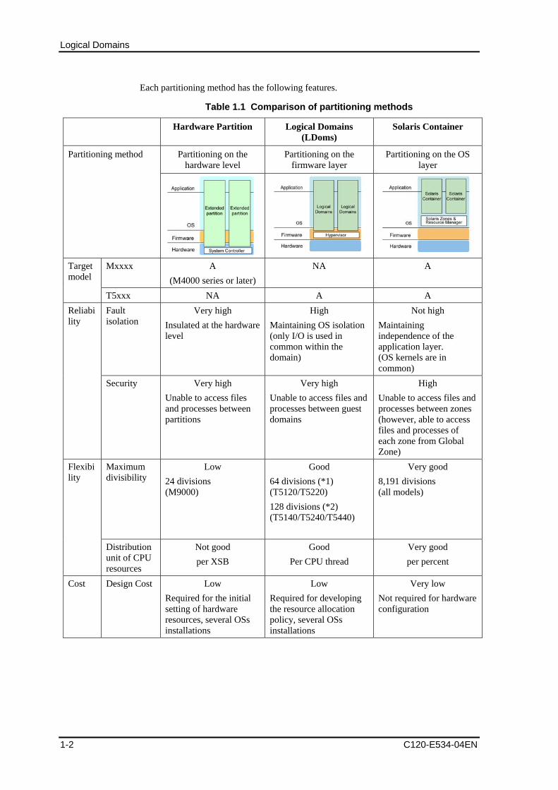
Each partitioning method has the following features.
Table 1.1 Comparison of partitioning methods
Hardware Partition Logical Domains (LDoms)
Solaris Container
Partitioning on the hardware level
Partitioning on the firmware layer
Partitioning on the OS layer
Partitioning method
Mxxxx A (M4000 series or later)
NA A Target model
T5xxx NA A A Fault isolation
Very high Insulated at the hardware level
High Maintaining OS isolation (only I/O is used in common within the domain)
Not high Maintaining independence of the application layer. (OS kernels are in common)
Reliability
Security Very high Unable to access files and processes between partitions
Very high Unable to access files and processes between guest domains
High Unable to access files and processes between zones (however, able to access files and processes of each zone from Global Zone)
Maximum divisibility
Low 24 divisions (M9000)
Good 64 divisions (*1) (T5120/T5220) 128 divisions (*2) (T5140/T5240/T5440)
Very good 8,191 divisions (all models)
Flexibility
Distribution unit of CPU resources
Not good per XSB
Good Per CPU thread
Very good per percent
Cost Design Cost Low Required for the initial setting of hardware resources, several OSs installations
Low Required for developing the resource allocation policy, several OSs installations
Very low Not required for hardware configuration
1-2 C120-E534-04EN

1.2 Differences Between Partitioning Methods
C120-E534-04EN 1-3
Hardware Partition Logical Domains (LDoms)
Solaris Container
Management Cost
Low
Required for managing several systems
Low
Required for managing several systems (OSs)
Very low
Only single OS system is managed. (application of OS patch) Setting/management of zones per task is required.
Operation continuity from the previous Solaris servers to SPARC Enterprise (Server aggregation)
Very good
The transition is available without any changes to the configuration/operation. (Only Solaris 10)
Very good
Transition is available without any changes to the configuration/operation (Only Solaris 10)
Not good
A review of the system configuration and its operation method for OS consolidation are required.
*1: control domain and 63 guest domains are configurable.
*2: control domain and 127 guest domains are configurable.

Logical Domains
1.3 The Basics of Hypervisor Ultra SPARC T2/T2 Plus processors have the following three operation modes.
• Nonprivileged mode (User mode)
• Privileged mode (Supervisor mode)
• Hyperprivileged mode (Hypervisor mode)
Figure 1.2 Operation modes of Ultra SPARC T2/T2 Plus processors
The hypervisor acquires control authority from the kernel (Supervisor mode) if required. It makes several kernels operate under the control of the hypervisor simultaneously.
The hypervisor is provided as a part of the firmware that is stored in EEPROM.
1-4 C120-E534-04EN

1.4 Role of the Domain in Logical Domains
C120-E534-04EN 1-5
1.4 Role of the Domain in Logical Domains In LDoms environment, Logical Domains are classified into four domains according to the role. • Control Domain
This is the domain in which the Logical Domains Manager is installed. This domain can create and manage other domains, and allocate a virtual resource. Only one control domain exists in a platform.
• I/O Domain
This is the domain that has an ownership of physical I/O devices such as PCI cards and has a direct access to them. The number of I/O domains differs according to platforms you are using.
This is the domain that directly accesses the peripherals to provide a virtual device service to other domains. The virtual device service includes disks, network devices and network switches. The control domain also functions as the service domain.
• Service Domain
This is the domain that provides virtual device services for other domains in cooperation with the I/O domain. The virtual device services contain disk, network, and console.
• Guest Domain
This is the domain that is managed by the control domain and uses the virtual device services provided by the I/O domain and service domain.
Independent OSs run in each logical domain.
One logical domain can have several roles. In general, the control domain is also used as the I/O domain and service domain. In this document, this is called as the control domain.
In addition, the guest domain is used as the I/O domain and service domain but another guest domain is not. In this document, the former is called as the guest domain (also used as the I/O domain), the latter is called as the guest domain.
Business Server1 Business Server2 Business Server3
Control Domain
Direct I/O
Virtual
Disk
Guest Domain
Virtual
Disk
Guest Domain
(I/ODomain)
Virtual
Disk
Guest Domain
Virtual
Disk
Direct I/O
Logical Domains
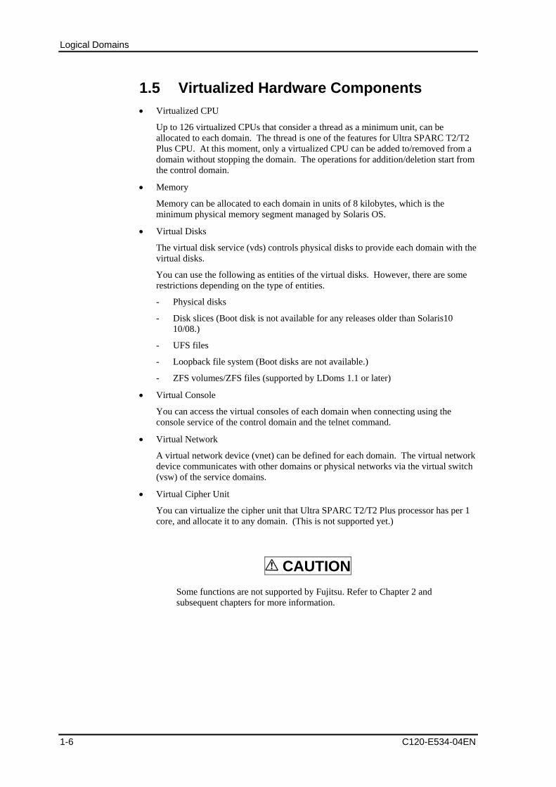
1.5 Virtualized Hardware Components • Virtualized CPU
Up to 126 virtualized CPUs that consider a thread as a minimum unit, can be allocated to each domain. The thread is one of the features for Ultra SPARC T2/T2 Plus CPU. At this moment, only a virtualized CPU can be added to/removed from a domain without stopping the domain. The operations for addition/deletion start from the control domain.
• Memory
Memory can be allocated to each domain in units of 8 kilobytes, which is the minimum physical memory segment managed by Solaris OS.
• Virtual Disks
The virtual disk service (vds) controls physical disks to provide each domain with the virtual disks.
You can use the following as entities of the virtual disks. However, there are some restrictions depending on the type of entities.
- Physical disks
- Disk slices (Boot disk is not available for any releases older than Solaris10 10/08.)
- UFS files
- Loopback file system (Boot disks are not available.)
- ZFS volumes/ZFS files (supported by LDoms 1.1 or later)
• Virtual Console
You can access the virtual consoles of each domain when connecting using the console service of the control domain and the telnet command.
• Virtual Network
A virtual network device (vnet) can be defined for each domain. The virtual network device communicates with other domains or physical networks via the virtual switch (vsw) of the service domains.
• Virtual Cipher Unit
You can virtualize the cipher unit that Ultra SPARC T2/T2 Plus processor has per 1 core, and allocate it to any domain. (This is not supported yet.)
CAUTION
Some functions are not supported by Fujitsu. Refer to Chapter 2 and subsequent chapters for more information.
1-6 C120-E534-04EN

1.6 Operating Environment of Logical Domains
C120-E534-04EN 1-7
1.6 Operating Environment of Logical Domains
Table 1.2 Operation environment
Hardware SPARC Enterprise T5120/T5220
Firmware 7.0.9 or later
Operating System Solaris10 OS 8/07 or later
Logical Domains Manager Software 1.0.2 or later
Required Patches 127111-09 or later
Recommended & Security Patches 139397-02 or later (LDoms Manager 1.0.2 ldmd patch)
Enhanced Support Facility (ESF) ESF 3.0A20 or later
When using ESF 3.0A20, the following patches must be applied.
914603-05 or later
914604-05 or later
914595-05 or later
Hardware SPARC Enterprise T5140/T5240
Firmware 7.1.3.d or later (7.1.6.d or later is recommended.)
Operating System Solaris10 OS 8/07 or later
Logical Domains Manager Software 1.0.3 or later
Required Patches 127111-11 or later
139562-02 or later
Recommended & Security Patches 139398-01 or later (LDoms Manager 1.0.3 ldmd patch)
Enhanced Support Facility (ESF) ESF 3.0.1 or later
When using ESF 3.0.1, the following patch must be applied.
• 914604-05 or later
Hardware SPARC Enterprise T5440
Firmware 7.1.7.d or later
Operating System Solaris10 OS 5/08 or later
Logical Domains Manager Software 1.0.3 or later
Required Patches 139562-02 or later
Recommended & Security Patches 139398-01 or later (LDoms Manager 1.0.3 ldmd patch)
Enhanced Support Facility (ESF) ESF 3.1 or later ( requires the following patch.)
• 914604-05 or later

Please use Logical Domains Manager 1.1 in the following environment.
Table1.3 Logical Domains Manager 1.1 environment Firmware 7.2.2.b or later is required. Operating System Solaris10 OS 10/08 or later is recommended. Required Patches (Control Domain) 139458-01 or later
139502-01 or later 139508-01 or later 139562-02 or later 139570-02 or later
Required Patches (Service Domain or I/O Domain)
139458-01 or later 139508-01 or later 139562-02 or later 139570-02 or later
Required Patches (Guest Domain) 139508-01 or later 139562-02 or later 139570-02 or later
Recommended & Security Patches 140809-02 or later
C120-E534-04EN 1-8
Chapter 2 LDoms Application
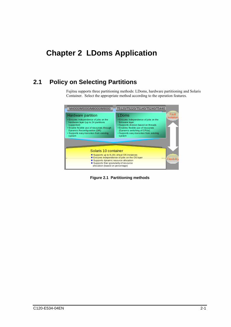
2.1 Policy on Selecting Partitions Fujitsu supports three partitioning methods: LDoms, hardware partitioning and Solaris Container. Select the appropriate method according to the operation features.
Faultisolation
Flexibility
Solaris 10 containerSupports up to 8,191 virtual OS instancesEnsures independence of jobs on the OS layerSupports dynamic resource allocationSupports finer granularity of resourceallocation (based on percentage)
Hardware partition• Ensures independence of jobs on thehardware layer (up to 24 partitions supported)
• Enable flexible use of resources throughDynamic Reconfiguration (DR)
• Supports easy transition from existingsystem
LDoms• Ensures independence of jobs on thefirmware layer
• Supports division based on threads • Enables flexible use of resources(Dynamic switching of CPUs)
• Supports easy trans ition from exis ting system
T5120/T5220/T5140/T5240/T5440M4000/M5000/M8000/M9000
Figure 2.1 Partitioning methods
C120-E534-04EN 2-1
LDoms Application
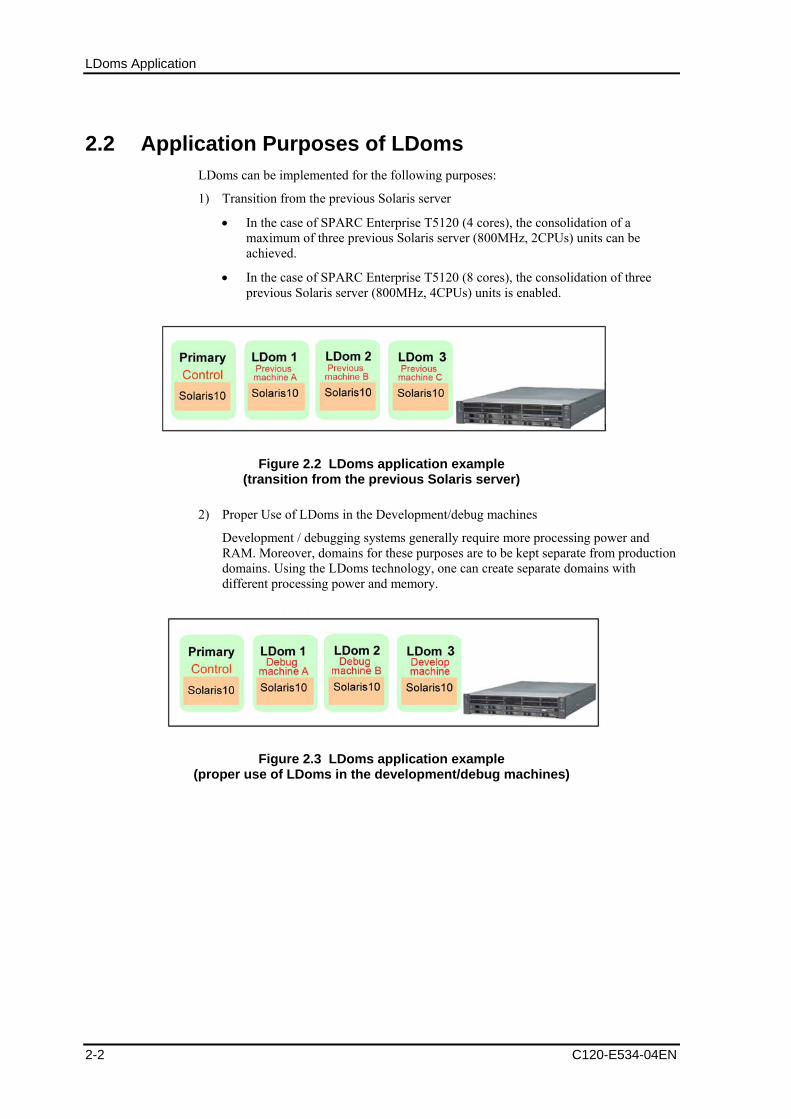
2.2 Application Purposes of LDoms LDoms can be implemented for the following purposes:
1) Transition from the previous Solaris server
• In the case of SPARC Enterprise T5120 (4 cores), the consolidation of a maximum of three previous Solaris server (800MHz, 2CPUs) units can be achieved.
• In the case of SPARC Enterprise T5120 (8 cores), the consolidation of three previous Solaris server (800MHz, 4CPUs) units is enabled.
Figure 2.2 LDoms application example (transition from the previous Solaris server)
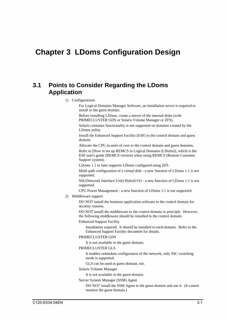
2) Proper Use of LDoms in the Development/debug machines
Development / debugging systems generally require more processing power and RAM. Moreover, domains for these purposes are to be kept separate from production domains. Using the LDoms technology, one can create separate domains with different processing power and memory.
Figure 2.3 LDoms application example (proper use of LDoms in the development/debug machines)
2-2 C120-E534-04EN

2.3 Operations for which LDoms can be used
2.3 Operations for which LDoms can be used LDoms operation depends on the control domain. There is little overhead, such as CPU/memory resource overhead. There is some virtual I/O overhead.
• Applicable operations are as follows: Web/AP servers
Software has a redundancy function provided by load balancing or middleware
• Middleware Agent and other applications
Software which can be restarted properly if stopped for any reason.
• Development machines
Operation continuity or high I/O performance comparable to that of real machines is not required.
1) Example of configuration for migration from previous servers
C
Primary Control
Figure 2.4 Example of configuration for migration from previous Solaris servers
C120-E534-04EN 2-3

LDoms Application
2) Example of configuration for migration from DB servers of previous Solaris servers.
Installation serverBackup server
Figure 2.5 Example of configuration for migration from DB servers of previous Solaris servers
2-4 C120-E534-04EN

2.3 Operations for which LDoms can be used
3) Example of configuration when using development machine/debug machine
Primary Control
Figure 2.6 Example of configuration when using development machine/debug machine
C120-E534-04EN 2-5

LDoms Application
2.4 LDoms Performance • There are few overheads of CPU/memory resource overhead.
• Allocate to the control domain/guest domain per core to avoid affecting the CPU load.
• SPARC Enterprise T5120/T5220 has only virtual I/O. Consider all operations, including those performed in the guest domain.
• The performance of the virtual I/O may be degraded compared to the performance of direct I/O, which handles I/O directly, because of the data transfers via the control domain. In case I/O performance is important, Fujitsu recommends advanced verification. Please contact the Platform Solution Center if a device for advanced verification is required.
• The CPU load of the control domain increases when the virtual network device (vnet) is used in the guest domain.
• Because the processing of each network card is allocated to a single CPU thread, please use the same number of network cards as that of the number of vnets and allocate the same number of CPU threads to the control domain.
2-6 C120-E534-04EN
Chapter 3 LDoms Configuration Design
3.1 Points to Consider Regarding the LDoms Application
1) Configurations � For Logical Domains Manager Software, an installation server is required to
install to the guest domain. � Before installing LDoms, create a mirror of the internal disks (with
PRIMECLUSTER GDS or Solaris Volume Manager or ZFS). � Solaris container functionality is not supported on domains created by the
LDoms utility. � Install the Enhanced Support Facility (ESF) to the control domain and guest
domain. � Allocate the CPU in units of core to the control domain and guest domains. � Refer to [How to set up REMCS in Logical Domains (LDoms)], which is the
ESF user's guide (REMCS version) when using REMCS (Remote Customer Support system).
� LDoms 1.1 or later supports LDoms configured using ZFS. � Multi path configuration of a virtual disk - a new function of LDoms 1.1 is not
supported. � NIU(Network Interface Unit) Hybrid I/O - a new function of LDoms 1.1 is not
supported. � CPU Power Management - a new function of LDoms 1.1 is not supported.
2) Middleware support � DO NOT install the business application software to the control domain for
security reasons. � DO NOT install the middleware to the control domain in principle. However,
the following middleware should be installed to the control domain. Enhanced Support Facility
Installation required. It should be installed to each domain. Refer to the Enhanced Support Facility document for details.
PRIMECLUSTER GDS It is not available in the guest domain.
PRIMECLUSTER GLS It enables redundant configuration of the network, only NIC switching mode is supported. GLS can be used in guest domain, too.
Solaris Volume Manager It is not available in the guest domain.
Server System Manager (SSM) Agent DO NOT install the SSM Agent to the guest domain and use it. (It cannot monitor the guest domain.)
C120-E534-04EN 3-1

LDoms Configuration Design
Power-off operation from SSM is disabled in the LDoms environment. � As for the guest domain, the middleware works normally on Solaris 10.
However, place the manager function of the middleware outside the guest domain and deploy only the agent in the guest domain because the manager function is required for high reliability.
� The operations of the following products are verified in the guest domain because of hardware is controlled/monitored directly.
3-2 C120-E534-04EN

3.1 Points to Consider Regarding the LDoms Application
Table 3.1 Supported Middleware Applications
Product Name Operations on guest domain
Remarks
Enhanced Support Facility
Available Installation to all domains is required.
Systemwalker CMGR Available The domain configuration is available only in the business server.
Systemwalker OMGR Available
Systemwalker SQC Available
� Contact the vendors in charge of each product about ISVs (Independent Software Vendors)/IHVs (Independent Hardware Vendors).
3) I/O Support
� The Direct I/O of the guest domain is not available in SPARC Enterprise T5120/T5220.
� The following I/Os are not available from the guest domain. - Graphic card - Serial port - USB - DVD equipment (*1)
*1: Available from the guest domain in Logical Domains Manager 1.0.3 Software or later.
- Use the tape equipment of the external server via a network when using the tape equipment from the guest domain.
4) Network
The NIC driver, which is allocated to the virtual switch (vsw), is a driver that is compliant only with the GLDv3 (Generic LAN Driver version3). The driver that is currently compliant with the network is the FUJITSU PCI GigabitEthernet(fjgi, version 4 or later)or e1000g, nxge.
5) Maintenance � The reconfiguration of LDoms is required to replace the hardware such as the
motherboard. You should control the information for the LDoms configuration setting, including backups.
C120-E534-04EN 3-3
LDoms Configuration Design
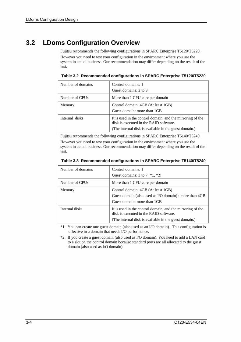
3.2 LDoms Configuration Overview Fujitsu recommends the following configurations in SPARC Enterprise T5120/T5220. However you need to test your configuration in the environment where you use the system in actual business. Our recommendation may differ depending on the result of the test.
Table 3.2 Recommended configurations in SPARC Enterprise T5120/T5220
Number of domains Control domains: 1 Guest domains: 2 to 3
Number of CPUs More than 1 CPU core per domain
Memory Control domain: 4GB (At least 1GB) Guest domain: more than 1GB
Internal disks
It is used in the control domain, and the mirroring of the disk is executed in the RAID software. (The internal disk is available in the guest domain.)
Fujitsu recommends the following configurations in SPARC Enterprise T5140/T5240. However you need to test your configuration in the environment where you use the system in actual business. Our recommendation may differ depending on the result of the test.
Table 3.3 Recommended configurations in SPARC Enterprise T5140/T5240
Number of domains Control domains: 1 Guest domains: 3 to 7 (*1, *2)
Number of CPUs More than 1 CPU core per domain
Memory Control domain: 4GB (At least 1GB) Guest domain (also used as I/O domain) : more than 4GBGuest domain: more than 1GB
Internal disks
It is used in the control domain, and the mirroring of the disk is executed in the RAID software. (The internal disk is available in the guest domain.)
*1: You can create one guest domain (also used as an I/O domain). This configuration is effective in a domain that needs I/O performance.
*2: If you create a guest domain (also used as I/O domain). You need to add a LAN card to a slot on the control domain because standard ports are all allocated to the guest domain (also used as I/O domain)
3-4 C120-E534-04EN
3.2 LDoms Configuration Overview
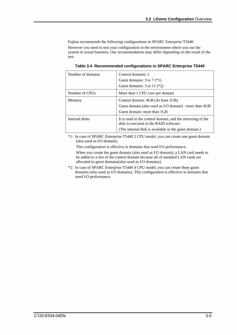
Fujitsu recommends the following configurations in SPARC Enterprise T5440. However you need to test your configuration in the environment where you use the system in actual business. Our recommendation may differ depending on the result of the test.
Table 3.4 Recommended configurations in SPARC Enterprise T5440
Number of domains Control domains: 1 Guest domains: 3 to 7 (*1) Guest domains: 3 to 11 (*2)
Number of CPUs More than 1 CPU core per domain
Memory Control domain: 4GB (At least 1GB) Guest domain (also used as I/O domain) : more than 4GBGuest domain: more than 1GB
Internal disks
It is used in the control domain, and the mirroring of the disk is executed in the RAID software. (The internal disk is available in the guest domain.)
*1: In case of SPARC Enterprise T5440 2 CPU model, you can create one guest domain (also used as I/O domain).
This configuration is effective in domains that need I/O performance. When you create the guest domain (also used as I/O domain), a LAN card needs to
be added to a slot of the control domain because all of standard LAN cards are allocated to guest domains(also used as I/O domains).
*2: In case of SPARC Enterprise T5440 4 CPU model, you can create three guest domains (also used as I/O domains). This configuration is effective in domains that need I/O performance.
C120-E534-04EN 3-5
LDoms Configuration Design
3.3 Points to Consider Regarding LDoms Configuration units
The hardware resources of CPU and memory are allocated as follows. • The CPU should be allocated per core unit to the control domain/guest domain. The
I/O connection is utilized for only the control domain in SPARC Enterprise T5120/T5220, so pay attention to all operations including those in the guest domain.
• The minimum memory requirement for control domain is 1GB, while the recommended amount is 4GB. Install more memory if necessary.
• Memory of the guest domain (also used as I/O domain), or of the control domain providing the virtual disk services to the guest domain needs to be added according to the disk I/O load of the guest domain.
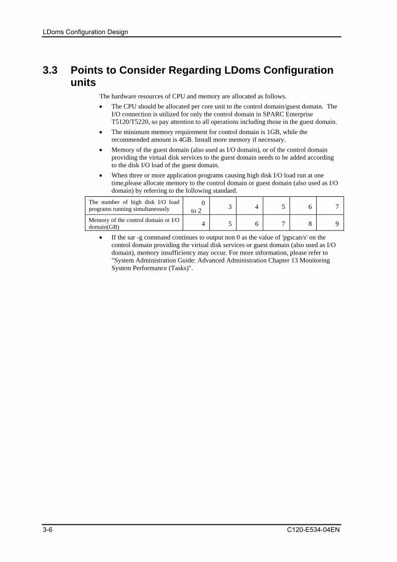
• When three or more application programs causing high disk I/O load run at one time,please allocate memory to the control domain or guest domain (also used as I/O domain) by referring to the following standard.
The number of high disk I/O load programs running simultaneously
0 to 2 3 4 5 6 7
Memory of the control domain or I/O domain(GB) 4 5 6 7 8 9
• If the sar -g command continues to output non 0 as the value of 'pgscan/s' on the control domain providing the virtual disk services or guest domain (also used as I/O domain), memory insufficiency may occur. For more information, please refer to "System Administration Guide: Advanced Administration Chapter 13 Monitoring System Performance (Tasks)".
3-6 C120-E534-04EN

3.4 Points to Consider Regarding I/O Construction
C120-E534-04EN 3-7
3.4 Points to Consider Regarding I/O Construction Points to note regarding I/O construction in the LDoms environment are explained in this section. The following domain can be configured in SPARC Enterprise T5xxx. • Control Domain • Guest Domain (also used as I/O domain) • Guest Domain If your computer operation requires a large amount of disk access in the guest domain (such as database access operation), please construct a guest domain (also used as I/O domain) that has direct access to disk devices. Applications or middlewares accessing disks frequently should be run in the guest domain (also used as I/O domain). When a large amount of network access occurs in the guest domain (like when file transfer is performed), configure the guest domain (also used as I/O domain) having direct access to a network card (such as Gigabit Ethernet card). If your application or middleware uses a large amount of network access, please try to run it on the guest domain (also used as I/O domain).
• Create one control domain. You cannot perform any business application on it. • In this example, the control domain and Business Server2 (guest domain) are also
used as the I/O domain and service domain. They can be configured not to have the role of the service domain.
• In this example, I/Os of Business Server1 and 3 (guest domains) are configured as virtualized I/Os.
• You can create no guest domain (also used as I/O domain) in SPARC Enterprise T5120, T5220.
Guest Domain
Control Domain
Virtual Disk Server
Virtual Disk Client
Guest Domain (also used as I/O)
Virtual Disk Server
Guest Domain
Virtual Disk Client
Business Server1 Business Server2 Business Server3
Real Disk
Direct I/O
Real Disk
Direct I/O
LDoms Configuration Design
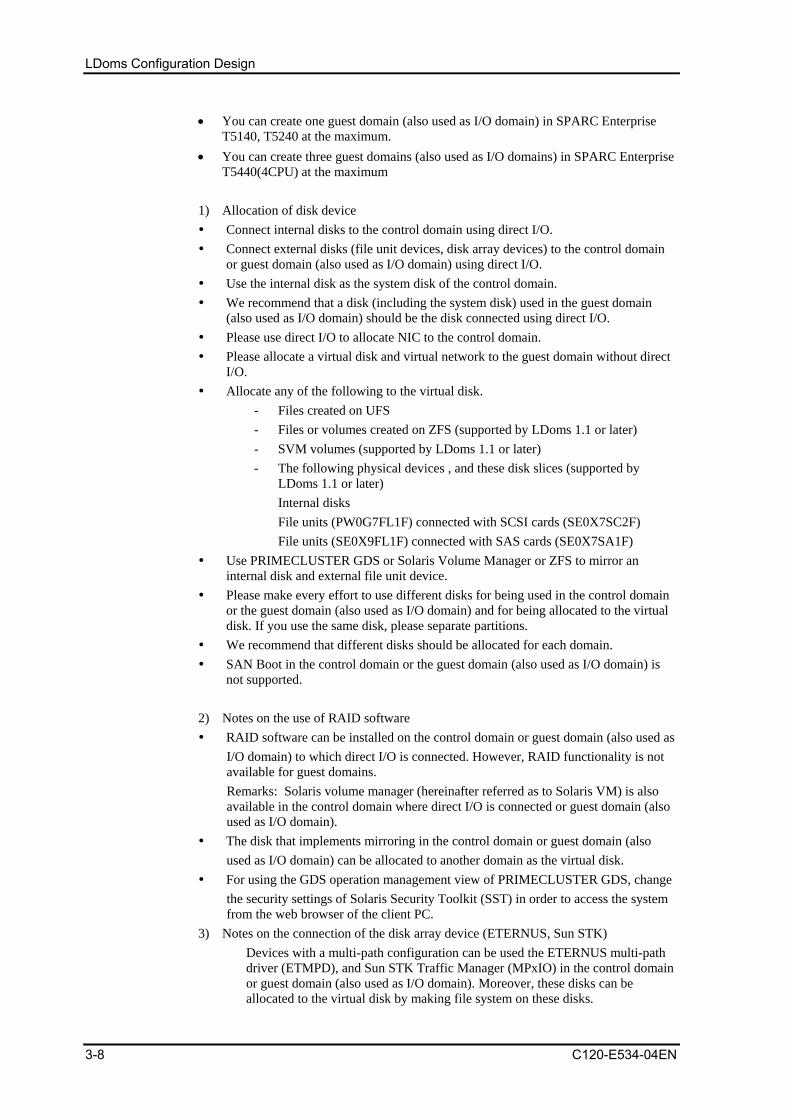
• You can create one guest domain (also used as I/O domain) in SPARC Enterprise T5140, T5240 at the maximum.
• You can create three guest domains (also used as I/O domains) in SPARC Enterprise T5440(4CPU) at the maximum
1) Allocation of disk device Connect internal disks to the control domain using direct I/O. Connect external disks (file unit devices, disk array devices) to the control domain
or guest domain (also used as I/O domain) using direct I/O. Use the internal disk as the system disk of the control domain. We recommend that a disk (including the system disk) used in the guest domain
(also used as I/O domain) should be the disk connected using direct I/O. Please use direct I/O to allocate NIC to the control domain. Please allocate a virtual disk and virtual network to the guest domain without direct
I/O. Allocate any of the following to the virtual disk.
- Files created on UFS - Files or volumes created on ZFS (supported by LDoms 1.1 or later) - SVM volumes (supported by LDoms 1.1 or later) - The following physical devices , and these disk slices (supported by
LDoms 1.1 or later) Internal disks File units (PW0G7FL1F) connected with SCSI cards (SE0X7SC2F) File units (SE0X9FL1F) connected with SAS cards (SE0X7SA1F)
Use PRIMECLUSTER GDS or Solaris Volume Manager or ZFS to mirror an internal disk and external file unit device.
Please make every effort to use different disks for being used in the control domain or the guest domain (also used as I/O domain) and for being allocated to the virtual disk. If you use the same disk, please separate partitions.
We recommend that different disks should be allocated for each domain. SAN Boot in the control domain or the guest domain (also used as I/O domain) is
not supported. 2) Notes on the use of RAID software RAID software can be installed on the control domain or guest domain (also used as
I/O domain) to which direct I/O is connected. However, RAID functionality is not available for guest domains. Remarks: Solaris volume manager (hereinafter referred as to Solaris VM) is also available in the control domain where direct I/O is connected or guest domain (also used as I/O domain).
The disk that implements mirroring in the control domain or guest domain (also used as I/O domain) can be allocated to another domain as the virtual disk.
For using the GDS operation management view of PRIMECLUSTER GDS, change the security settings of Solaris Security Toolkit (SST) in order to access the system from the web browser of the client PC.
3) Notes on the connection of the disk array device (ETERNUS, Sun STK) � Devices with a multi-path configuration can be used the ETERNUS multi-path
driver (ETMPD), and Sun STK Traffic Manager (MPxIO) in the control domain or guest domain (also used as I/O domain). Moreover, these disks can be allocated to the virtual disk by making file system on these disks.
3-8 C120-E534-04EN

3.4 Points to Consider Regarding I/O Construction
C120-E534-04EN 3-9
[Configuration Example 1] This section indicates how to build the LDoms in the internal disk. Refer to this example when the dedicated device can be allocated to the control domain or to each guest domain. The disks allocated to each domain are available as system disks or data disks. Points to consider regarding construction 1) All of the internal disks connect to the control domain by Direct I/O. 2) The control domain uses internal disks. 3) The mirroring of all internal disks is executed in the control domain.
Remarks: PRIMECLUSTER GDS (GDS) and Solaris Volume Manager (Solaris VM) and ZFS are available.
4) UFS file system is initialized on each guest domain and mounted on the control domain.
5) Create a file to be allocated as the virtual disk on each UFS file system. Remarks: In the following example, one file is created on each of three UFS file
systems. 6) The created file is used to allocate a virtual disk to each guest domain.
Control domain
Mirrored by GDS/Solaris VM
UFS
Guest Domain A
VirtualDisk
Guest Domain B
Guest Domain C
Virtual Disk
VirtualDisk
HDD4 HDD5 HDD6 HDD7
Built-in Disk CD GD CGD BGD A
Mirrored by GDS/Solaris VM
HDD1 HDD2 HDD3HDD0
Figure 3.1 Example 1 Configuration when building the LDoms in the internal disk

LDoms Configuration Design
3-10 C120-E534-04EN
[Configuration Example 2] Refer to this example when the number of available disks are less than the sum of the number of control and guest domains, so that the disks are to be shared between the control and guest domains. The disks allocated to each domain are available as the system disk or data disk. Points to consider regarding construction 1) The internal disks connect to the control domain through Direct I/O. 2) The internal disks are divided into slices for allocation to the control and guest
domains. Remarks: You do not have to divide the partition for each guest domain if there are
several guest domains. 3) The control domain uses partitions for itself. 4) All internal disks of the control domain are mirrored.(PRIMECLUSTER GDS (GDS)
and Solaris Volume Manager (SVM) and ZFS are available as mirroring software.) 5) Allocate dedicated disks to each guest domain, initialize UFS on them and mount
them on the control domain. 6) Create a file to be allocated as the virtual disk on each UFS file system.
Remarks: In the following example, one file is created on each of three UFS file systems.
7) The created file is used to allocate a virtual disk to each guest domain.
Control domain
Mirrored by GDS/SolarisVM
UFS
Guest Domain A
Virtualdisk
Guest Domain B
Guest Domain C
Virtual
disk Virtual
disk
Built-in disk
Mirroring by GDS/Solaris VM
HDD0
HDD1
Partition for guest domain
Partition for control domain
Partition for guest domain
Partition for control domain
Figure 3.2 Example 2 Configuration when building the LDoms in the internal disk
[Configuration Example 3] This section describes how to create logical domains on internal disks and external file unit devices. The disks allocated to each domain are available as the system disk or data disk.

3.4 Points to Consider Regarding I/O Construction
Points to consider regarding construction 1) To mirror the control domain, use internal disks connected by using direct I/O.
Remarks: You can use GDS, Solaris VM, ZFS. 2) Connect external file unit to the control domain using direct I/O. 3) Mirror disks of external file unit in the control domain.
Remarks: You can use GDS, Solaris VM, ZFS. 4) Allocate dedicated disks to each guest domain and initialize UFS on them and mount
them on the control domain. 5) Create a file to be allocated as the virtual disk on each UFS file system.
Remarks: In the following example, one file is created on each of three UFS file systems.
6) The created file is used to allocate a virtual disk to each guest domain.
Control Domain
Mirrored by GDS/Solaris VM
UFS
Guest Domain A
Virtual Disk
Guest Domain B
Virtual Disk
Virtual Disk
For Control Domain
Mirroring by GDS/Solaris VM
Internal Disk
For Control Domain
HDD4
HDD5
HDD6
HDD1
HDD3
Mirroring by GDS/Solaris VM
GuestDomain A
Guest Domain C
GuestDomain B
External File Unit
HDD2
Guest Domain C
Figure 3.3 Example 1 Configuration when building the LDoms using direct I/O
[Configuration Example 4] This section describes another procedure of creating logical domains on internal disks and external file unit devices. The disks allocated to each domain are available as the system disk or data disk. Points to consider regarding construction
C120-E534-04EN 3-11

LDoms Configuration Design
1) All of the internal disks connect to the control domain by Direct I/O. 2) The control domain uses internal disks. 3) The mirroring of all internal disks is executed in the control domain.
Remarks: PRIMECLUSTER GDS (GDS) and Solaris Volume Manager (Solaris VM) and ZFS are available.
4) Allocate a disk for Guest Domain A and initialize UFS file system on Guest Domain A and mount it on the control domain.
5) Create a file to be allocated as the virtual disk on each UFS file system. 6) The created file is used to allocate a virtual disk to Guest Domain A. 7) Connect external file unit to Guest Domain B using direct I/O. 8) Guest Domain B used disks connected by using direct I/O. 9) Mirror disks of external file unit in Guest Domain B.
Remarks: You can use GDS, Solaris VM, ZFS, ZFS. 10) Allocate dedicated disks for Guest Domain C and initialize UFS on it and mount it
on the control domain. 11) Create a file to be allocated as the virtual disk on each UFS file system. 12) The created file is used to allocate a virtual disk to Guest Domain C.
Control Domain
Mirrored by GDS/Solaris VM
UFS
Guest Domain A
Virtual Disk
Guest Domain C
Virtual Disk
HDD2
HDD3
HDD0
Guest Domain B
Mirroring by GDS/Solaris VM
Mirrored by GDS/Solaris VM
HDD2
HDD3
Mirroring by GDS/Solaris VM
UFS
Internal Disk
Guest Domain C
Guest Domain B
Guest Domain A
Control Domain
External File Unit
HDD1
HDD0
HDD1
Figure 3.4 Example 2 Configuration when building the LDoms using direct I/O
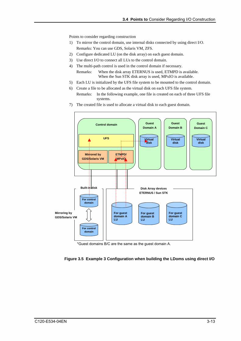
[Configuration Example 5] This section describes how to connect disk array devices to the control domain in order to configure LDoms. The disks allocated to each domain are available as the system disk or data disk.
3-12 C120-E534-04EN
3.4 Points to Consider Regarding I/O Construction
Points to consider regarding construction 1) To mirror the control domain, use internal disks connected by using direct I/O.
Remarks: You can use GDS, Solaris VM, ZFS. 2) Configure dedicated LU (on the disk array) on each guest domain. 3) Use direct I/O to connect all LUs to the control domain. 4) The multi-path control is used in the control domain if necessary.
Remarks: When the disk array ETERNUS is used, ETMPD is available. When the Sun STK disk array is used, MPxIO is available.
5) Each LU is initialized by the UFS file system to be mounted to the control domain. 6) Create a file to be allocated as the virtual disk on each UFS file system.
Remarks: In the following example, one file is created on each of three UFS file systems.
7) The created file is used to allocate a virtual disk to each guest domain.
Guest Domain A
Virtualdisk
Guest Domain B
Guest Domain C
Virtualdisk
Virtual disk
Disk Array devices ETERNUS / Sun STK
For guest domain A LU
For guest domain B LU
For guest domain C LU
Control domain
ETMPD/ MPxIO
UFS
Mirrored by GDS/Solaris VM
For control domain
Built-in disk
For control domain
Mirroring by GDS/Solaris VM
*Guest domains B/C are the same as the guest domain A.
Figure 3.5 Example 3 Configuration when building the LDoms using direct I/O
C120-E534-04EN 3-13

LDoms Configuration Design
[Configuration Example 6] This section describes how to configure LDoms by using internal disks. The disks allocated to each domain are available as the system disk or data disk. Points to consider regarding construction 1) The internal disks connect to the control domain through Direct I/O. 2) The control domain uses internal disks. 3) All internal disks of the control domain are mirrored.(PRIMECLUSTER GDS (GDS)
and Solaris Volume Manager (SVM) and ZFS are available as mirroring software.) 4) Allocate dedicated disks to Guest Domain A,B, initialize UFS on them and mount
them on the control domain. 5) Create a file to be allocated as the virtual disk on each UFS file system.
Remarks: In the following example, one file is created on each of two UFS file systems.
6) The created file is used to allocate a virtual disk to each guest domain. 7) Configure dedicated LU (on the disk array) on Guest Domain C. 8) Use direct I/O to connect all LUs to Guest Domain C. 9) Guest Domain C uses disks connected by using direct I/O. 10) The multi-path control is used in the control domain if necessary.
Remarks: When the disk array ETERNUS is used, ETMPD is available. When the Sun STK disk array is used, MPxIO is available.
3-14 C120-E534-04EN
Guest Domain A
Guest Domain B
Control Domain
Figure 3.6 Example 4 Configuration when building the LDoms using direct I/O
Mirrored by GDS/Solaris VM
UFS Virtual Disk
Virtual Disk
HDD3
HDD4
HDD0
Guest Domain C
ETMPD/ MPxIO
UFS
HDD1
HDD5
HDD2
Disk Array Device ETERNUS / Sun STK
LU For Guest Domain B
LU For Guest Domain C
Internal Disks
Control Domain
Guest Domain A
Guest Domain B
Mirroring by GDS/Solaris VM

3.4 Points to Consider Regarding I/O Construction
C120-E534-04EN 3-15
[Configuration Example 7] Here, the method of configuring LDoms on Solaris VM using an internal disk and external file unit device is explained. A disk allocated to each domain can be used as a system disk, or data disk. Points to consider regarding construction 1) Connect the internal disk to the control domain using direct I/O. 2) Use the internal disk for the control domain. 3) Perform the mirroring of the internal disk in the control domain with Solaris VM. 4) Allocate Solaris VM volume created in a disk used for guest domain A to guest
domain A as a virtual disk. 5) Connect the external file unit to guest domain B using direct I/O. 6) Guest domain B will use a disk connected using direct I/O. 7) Perform the mirroring of the disk of the external file unit in guest domain B with
Solaris VM. 8) Allocate Solaris VM volume created in a disk used for guest domain C to guest
domain C as a virtual disk.
Control Domain
Mirrord by
Solaris VM
Guest Domain A
VirtualDisk
Guest Domain C
Virtual Disk
制御ドメインゲストドメイン A
HDD2 HDD3
HDD0
Mirroring by Solaris VM
Guest Domain B ドメインB
Mirrored by
Solaris VM
HDD2 HDD3
Mirroring by Solaris VM
Control Domain
GuestDomainA
HDD1
GuestDomainB
Guest DomainC
HDD0 HDD1
Internal Diaks External File Unit
UFS UFS
Figure 3.7 Example 5 Configuration when building the LDoms using direct I/O

LDoms Configuration Design
3-16 C120-E534-04EN
[Configuration Example 8] Here the method of configuring LDoms in an internal disk when ZFS file is allocated as a virtual disk is explained. Points to consider regarding construction 1) Connect the internal disk to the control domain using direct I/O. 2) Use the internal disk for the control domain. 3) Allocate an exclusive disk to each guest domain, and initialize it with ZFS to mount
the control domain. 4) Create a file to be allocated as a virtual disk on the mounted ZFS. 5) Allocate the created file to each guest domain as a virtual disk.
Control Domain
ZFS
Guest DomainA
VirtualDisk
Guest DomainB
VirtualDisk
HDD4 HDD5 HDD6
Internal Disks Control Domain
GuestDomainB
GuestDomainA
Mirroring by ZFS
HDD1 HDD2 HDD0
Figure 3.8 Example 3 Configuration when building the LDoms in the internal disk

3.5 Points to Consider Regarding Network Construction
3.5 Points to Consider Regarding Network Construction Points on and notes on the network construction in the LDoms environments are explained in this section. 1) Allocation of the virtual switch (vsw) or virtual network device (vnet)
� Fujitsu recommends allocating the vsw service for each different NIC and allocating the vnet according to the following configuration example. When consolidating the vnet of several guest domains to the vsw that is allocated to one NIC, the upper limit of the throughput sum for each vnet is limited to one NIC throughput.
[Configuration example]
Guest Domain A
Guest Domain B
Guest Domain C
Control domain
NIC#0 NIC#1 NIC#2 NIC#3
vsw1
vnet1 vnet1 vnet1
vsw2 vsw3
Figure 3.9 Allocation of the virtual switch (vsw) or virtual network device (vnet)
� DO NOT allocate more than 32 vnet for one vsw service. The load for the control domain may become very high, leading to a suspension of system operations.
� LDoms Manager 1.1 or later supports VLAN of vnet. 2) Multi-path and NIC redundant configuration
� The combination of the Link Aggregation function in the standard Solaris 10 OS and LDoms is not supported.
� The NIC redundant configuration will be available when the IP network multi-path (IPMP) function in the standard Solaris 10 OS is combined with LDoms. - Notes on the IPMP configuration in the guest domain
This configuration can be used only for fault detection with the test signal. Fault detection by monitoring the link state is not supported.
C120-E534-04EN 3-17

LDoms Configuration Design
[Configuration example]
Guest Domain A
Control domain
NIC#0 NIC#1 NIC#2
vsw1
vnet1 vnet2
vsw2
IPMP group
Figure 3.10 Multi-path and NIC redundant configuration
- Notes on setting multi-path configuration with the control domain Fault detection via a test signal and via link state monitoring are available.
[Configuration example]
IPMP group
Guest domain A
Control domain
NIC#0 NIC#1
vsw0
vnet0 IP
(Routing)
Figure 3.11 Multi-path configuration with control domain
3-18 C120-E534-04EN

3.5 Points to Consider Regarding Network Construction
C120-E534-04EN 3-19
3) Notes on LAN in SPARC Enterprise T5140/T5240/T5440 � The following ports are unavailable due to incompatibility on the system loading
10GbitEthernet XAUI card. � (In case of SPARC Enterprise T5140/T5240)
XAUI card installation location
Unavailable Standard LAN Ports
Slot 0 NET1
Slot 1 NET0
� � (In case of SPARC Enterprise T5440)
XAUI card installation location
Unavailable Standard LAN Ports
Slot 4 NET1
Slot 5 NET0
� When you configure the guest domain (also used as I/O domain) on SPARC Enterprise T5140/T5240, standard LAN ports are allocated to the guest domain (also used as I/O domain). Therefore you need to add a LAN card to the control domain.
Figure 3.12 In case of SPARC Enterprise T5140
Guest Domain A (Also used as I/O Domain)
PC
Ie0
PC
Ie2
PC
Ie1
NE
T3
NE
T2
NE
T1
NE
T0
Control Domain
vsw2
Guest Domain B
Guest Domain C
vnet1 vnet1
vsw1
Adding a LAN card is required.Incompatible with XAUI card Incompatible with XAUI card
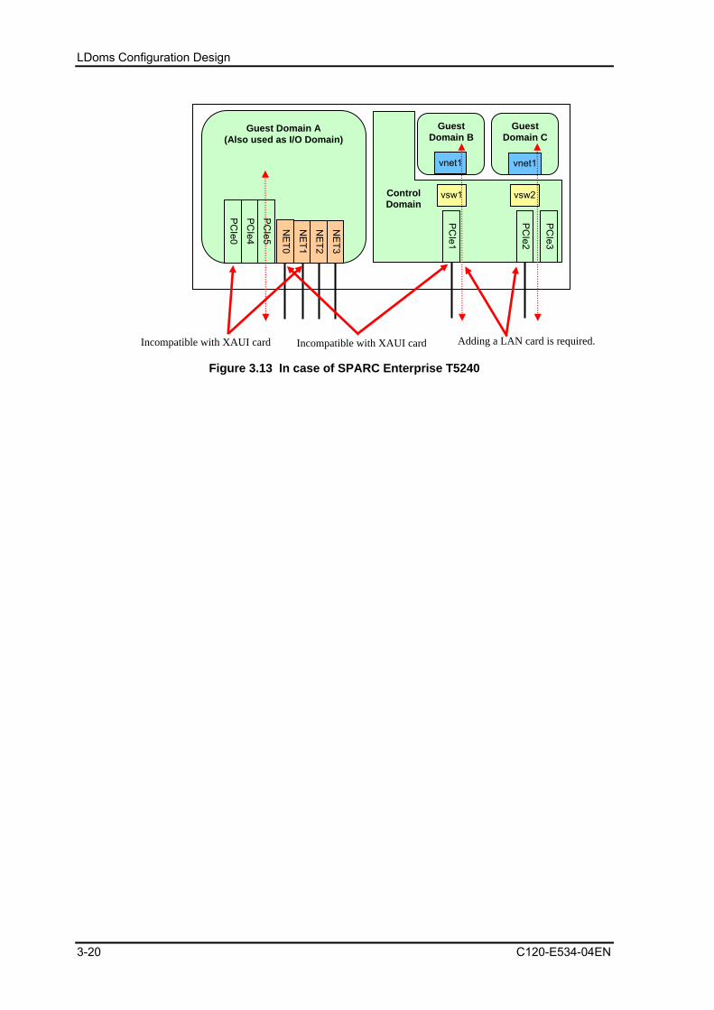
LDoms Configuration Design
3-20 C120-E534-04EN
Guest Domain A (Also used as I/O Domain)
PC
Ie0
Figure 3.13 In case of SPARC Enterprise T5240
PC
Ie2
PC
Ie1
NE
T1
NE
T2
NE
T3
NE
T0
Control Domain
vsw2
Guest Domain B
Guest Domain C
vnet1 vnet1
vsw1
Adding a LAN card is required. Incompatible with XAUI card Incompatible with XAUI card
PC
Ie3
PC
Ie4
PC
Ie5
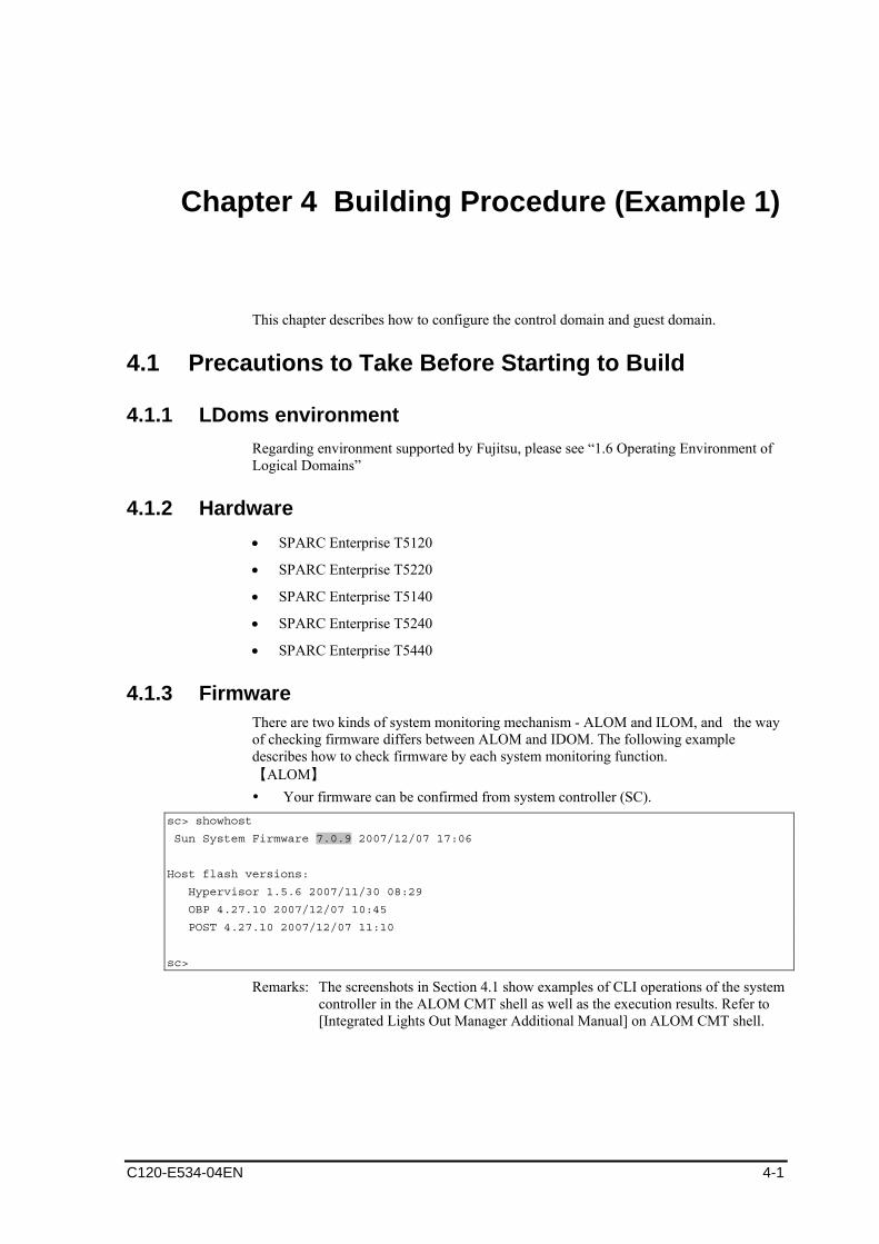
Chapter 4 Building Procedure (Example 1)
This chapter describes how to configure the control domain and guest domain.
4.1 Precautions to Take Before Starting to Build
4.1.1 LDoms environment Regarding environment supported by Fujitsu, please see “1.6 Operating Environment of Logical Domains”
4.1.2 Hardware • SPARC Enterprise T5120
• SPARC Enterprise T5220
• SPARC Enterprise T5140
• SPARC Enterprise T5240
• SPARC Enterprise T5440
4.1.3 Firmware There are two kinds of system monitoring mechanism - ALOM and ILOM, and the way of checking firmware differs between ALOM and IDOM. The following example describes how to check firmware by each system monitoring function. 【ALOM】 Your firmware can be confirmed from system controller (SC).
sc> showhost
Sun System Firmware 7.0.9 2007/12/07 17:06
Host flash versions:
Hypervisor 1.5.6 2007/11/30 08:29
OBP 4.27.10 2007/12/07 10:45
POST 4.27.10 2007/12/07 11:10
sc>
Remarks: The screenshots in Section 4.1 show examples of CLI operations of the system controller in the ALOM CMT shell as well as the execution results. Refer to [Integrated Lights Out Manager Additional Manual] on ALOM CMT shell.
C120-E534-04EN 4-1

Building Procedure (Example 1)
【ILOM】 -> show /HOST /HOST Targets: bootmode diag domain Properties: autorestart = reset autorunonerror = false bootfailrecovery = poweroff bootrestart = none boottimeout = 0 hypervisor_version = Hypervisor 1.7.0 2008/12/11 13:40 macaddress = 00:14:4f:46:e8:12 maxbootfail = 3 obp_version = OBP 4.30.0 2008/12/11 12:16 post_version = POST 4.30.0 2008/12/11 12:44 send_break_action = (none) status = Solaris running sysfw_version = Sun System Firmware 7.2.0 2008/12/11 17:58 Commands: cd set show
4.1.4 Logical domains manager software (LDoms manager) The installed LDoms Manager can be checked using the following method.
# pkginfo -l SUNWldm|grep VERSION
VERSION: 1.0.2,REV=2008.02.11.14.26
When an unsupported package is installed, remove it by using the following procedure. # pkginfo -l SUNWldm|grep VERSION
VERSION: 1.0.1,REV=2007.08.23.10.20
# svcadm disable ldmd
# svcadm disable vntsd
# pkgrm SUNWldm SUNWjass
The following package is installed:
SUNWldm Logical Domains Manager
(sparc.sun4v) 1.0.1,REV=2007.08.23.10.20
Do you delete this package? [y,n,?,q] y
...
After removing the package, download the LDoms manager from the following official Fujitsu site:
http://www.fujitsu.com/global/services/computing/server/sparcenterprise/downloads/
4.1.5 Operating system (OS) for the control domain • Solaris 10 OS 8/07 or later
• Required patch
• Cluster specified and installed with Core System Support (SUNWCreq) or higher
4-2 C120-E534-04EN
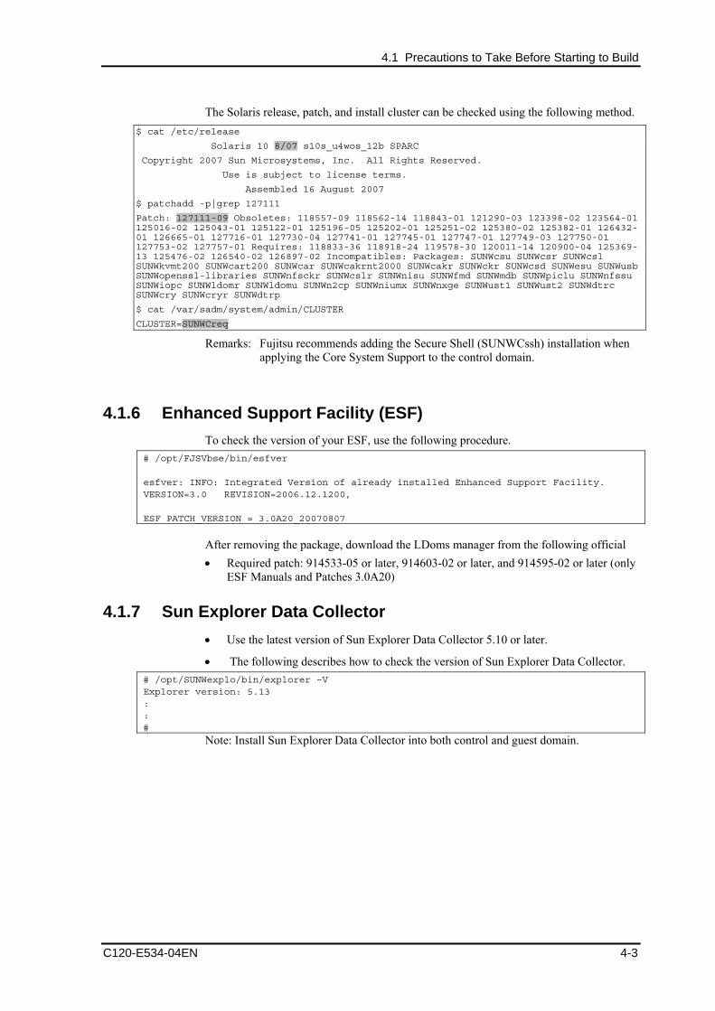
4.1 Precautions to Take Before Starting to Build
The Solaris release, patch, and install cluster can be checked using the following method. $ cat /etc/release
Solaris 10 8/07 s10s_u4wos_12b SPARC
Copyright 2007 Sun Microsystems, Inc. All Rights Reserved.
Use is subject to license terms.
Assembled 16 August 2007
$ patchadd -p|grep 127111
Patch: 127111-09 Obsoletes: 118557-09 118562-14 118843-01 121290-03 123398-02 123564-01 125016-02 125043-01 125122-01 125196-05 125202-01 125251-02 125380-02 125382-01 126432-01 126665-01 127716-01 127730-04 127741-01 127745-01 127747-01 127749-03 127750-01 127753-02 127757-01 Requires: 118833-36 118918-24 119578-30 120011-14 120900-04 125369-13 125476-02 126540-02 126897-02 Incompatibles: Packages: SUNWcsu SUNWcsr SUNWcsl SUNWkvmt200 SUNWcart200 SUNWcar SUNWcakrnt2000 SUNWcakr SUNWckr SUNWcsd SUNWesu SUNWusb SUNWopenssl-libraries SUNWnfsckr SUNWcslr SUNWnisu SUNWfmd SUNWmdb SUNWpiclu SUNWnfssu SUNWiopc SUNWldomr SUNWldomu SUNWn2cp SUNWniumx SUNWnxge SUNWust1 SUNWust2 SUNWdtrc SUNWcry SUNWcryr SUNWdtrp
$ cat /var/sadm/system/admin/CLUSTER
CLUSTER=SUNWCreq
Remarks: Fujitsu recommends adding the Secure Shell (SUNWCssh) installation when applying the Core System Support to the control domain.
4.1.6 Enhanced Support Facility (ESF) To check the version of your ESF, use the following procedure.
# /opt/FJSVbse/bin/esfver esfver: INFO: Integrated Version of already installed Enhanced Support Facility. VERSION=3.0 REVISION=2006.12.1200, ESF PATCH_VERSION = 3.0A20_20070807
After removing the package, download the LDoms manager from the following official • Required patch: 914533-05 or later, 914603-02 or later, and 914595-02 or later (only
ESF Manuals and Patches 3.0A20)
4.1.7 Sun Explorer Data Collector • Use the latest version of Sun Explorer Data Collector 5.10 or later.
• The following describes how to check the version of Sun Explorer Data Collector. # /opt/SUNWexplo/bin/explorer –V Explorer version: 5.13 : : #
Note: Install Sun Explorer Data Collector into both control and guest domain.
C120-E534-04EN 4-3
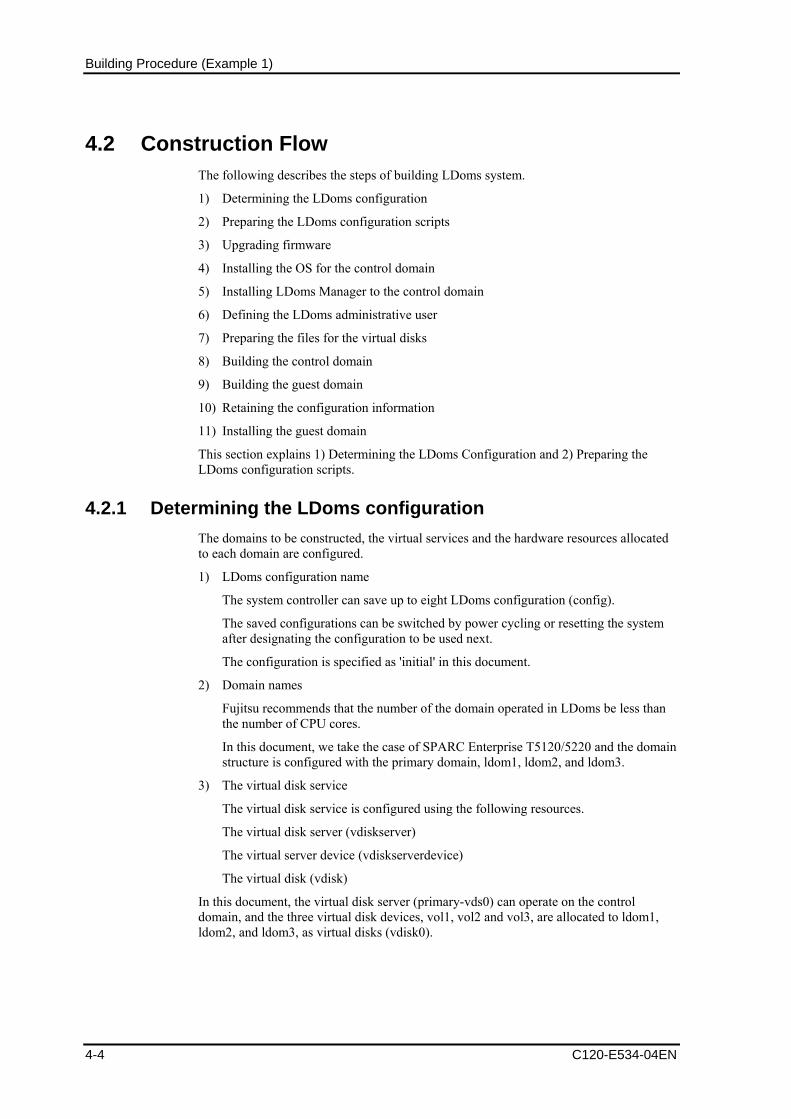
Building Procedure (Example 1)
4.2 Construction Flow The following describes the steps of building LDoms system.
1) Determining the LDoms configuration
2) Preparing the LDoms configuration scripts
3) Upgrading firmware
4) Installing the OS for the control domain
5) Installing LDoms Manager to the control domain
6) Defining the LDoms administrative user
7) Preparing the files for the virtual disks
8) Building the control domain
9) Building the guest domain
10) Retaining the configuration information
11) Installing the guest domain
This section explains 1) Determining the LDoms Configuration and 2) Preparing the LDoms configuration scripts.
4.2.1 Determining the LDoms configuration The domains to be constructed, the virtual services and the hardware resources allocated to each domain are configured.
1) LDoms configuration name
The system controller can save up to eight LDoms configuration (config).
The saved configurations can be switched by power cycling or resetting the system after designating the configuration to be used next.
The configuration is specified as 'initial' in this document.
2) Domain names
Fujitsu recommends that the number of the domain operated in LDoms be less than the number of CPU cores.
In this document, we take the case of SPARC Enterprise T5120/5220 and the domain structure is configured with the primary domain, ldom1, ldom2, and ldom3.
3) The virtual disk service
The virtual disk service is configured using the following resources.
The virtual disk server (vdiskserver)
The virtual server device (vdiskserverdevice)
The virtual disk (vdisk)
In this document, the virtual disk server (primary-vds0) can operate on the control domain, and the three virtual disk devices, vol1, vol2 and vol3, are allocated to ldom1, ldom2, and ldom3, as virtual disks (vdisk0).
4-4 C120-E534-04EN
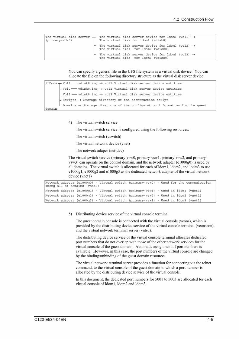
4.2 Construction Flow
The virtual disk server The virtual disk server device for ldom1 (vol1) → (primary-vds0) The virtual disk for ldom1 (vdisk0)
The virtual disk server device for ldom2 (vol2) → The virtual disk for ldom2 (vdisk0)
The virtual disk server device for ldom3 (vol3) → The virtual disk for ldom3 (vdisk0)
You can specify a general file in the UFS file system as a virtual disk device. You can allocate the file on the following directory structure as the virtual disk server device.
/LDoms Vol1 vdisk0.img → vol1 Virtual disk server device entities
Vol2 vdisk0.img → vol2 Virtual disk server device entities
Vol3 vdisk0.img → vol3 Virtual disk server device entities
Scripts → Storage directory of the cosntruction script
Domains → Storage directory of the configuration information for the guest domain
4) The virtual switch service
The virtual switch service is configured using the following resources.
The virtual switch (vswitch)
The virtual network device (vnet)
The network adaper (net-dev)
The virtual switch service (primary-vsw0, primary-vsw1, primary-vsw2, and primary-vsw3) can operate on the control domain, and the network adapter (e1000g0) is used by all domains. The virtual switch is allocated for each of ldom1, ldom2, and lodm3 to use e1000g1, e1000g2 and e1000g3 as the dedicated network adapter of the virtual network device (vnet1)
Network adapter (e1000g0) - Virtual switch (primary-vsw0) - Used for the communication among all of domains (vnet0)
Network adapter (e1000g1) - Virtual switch (primary-vsw1) - Used in ldom1 (vnet1)
Network adapter (e1000g2) - Virtual switch (primary-vsw2) - Used in ldom2 (vnet1)
Network adapter (e1000g3) - Virtual switch (primary-vsw3) - Used in ldom3 (vnet1)
5) Distributing device service of the virtual console terminal
The guest domain console is connected with the virtual console (vcons), which is provided by the distributing device service of the virtual console terminal (vconscon), and the virtual network terminal server (vntsd).
The distributing device service of the virtual console terminal allocates dedicated port numbers that do not overlap with those of the other network services for the virtual console of the guest domain. Automatic assignment of port numbers is available. However, in this case, the port numbers of the virtual console are changed by the binding/unbinding of the guest domain resources.
The virtual network terminal server provides a function for connecting via the telnet command, to the virtual console of the guest domain to which a port number is allocated by the distributing device service of the virtual console.
In this document, the dedicated port numbers for 5001 to 5003 are allocated for each virtual console of ldom1, ldom2 and ldom3.
C120-E534-04EN 4-5

Building Procedure (Example 1)
4.2.2 Creating the allocation sheet for hardware resources The following allocation sheet for the hardware resources is created.
Table 4.1 Hardware resource allocation
Configuration name
(CONFIG)
Initial Remarks
Domain name (DOMAIN)
primary ldom1 ldom2 ldom3 This is the name used for control by LDoms Manager.
It is not linked to the host name or node name.
Virtual CPU numbers (VCPU)
8 16 16 24 Specify a multiple of the number of threads per CPU core.
Memory (MEM) 4096M 1920M 1024M 1024M The following sizes (*1) used by firmware cannot be allocated.
T5120/T5220: 128MB T5140/T5240: 224MB
T5440: 340MB
Eliminate 128MB from the allocation for the firmware.
When 1024MB is allocated, enter [1024M], and when allocating 4GB, enter [4G].
Cryptographic device *(MAU)
0 0 0 0 Specify the MAU unit number. Specify "0" when using the active reconfiguration of CPU. You cannot allocate the MAU beyond the CPU core numbers.
Virtual network device 0(VNET0)
vsw0 vsw0 vsw0 Specify the virtual switch service to connect to virtual network device 0.
Virtual network device 1(VNET1)
vsw1 vsw2 vsw3 Specify the virtual switch service to connect to virtual network device 1.
Virtual disk 0(VDISK0)
vol1 vol2 vol3 Specify the virtual disk server device to allocate to virtual disk 0.
Virtual console (VCONS)
5001 5002 5003 Specify the port number to allocate to the virtual console.
*1: Sizes used by firmware may differ depending on machine model or firmware version. Please check available sizes by seeing the result of output of the command below.
Primary# ldm list-device -a
4-6 C120-E534-04EN

4.2 Construction Flow
4.2.3 Preparing the LDoms configuration script The control domain configuration script and the guest domain configuration script are created with the allocation sheet of the hardware resources that are created in the LDoms configuration. Save the created script in the directory for the LDoms configuration script (/LDoms/Scripts/) to make the script operable as required.
1) Creation of the Control domain configuration scripts
The following is an example of the control domain configuration script.
Set the values of the allocation sheet of the hardware resources to the shell variables (CONFIG, VCPU, MAU, MEM).
#!/bin/sh
# Control domain configuration script (for 4 domains)
CONFIG=initial # Configuration name to store in the system controller
VCPU=8 # Virtual CPU numbers to allocate to the control domain
MAU=0 # MAU numbers to allocate to the control domain
MEM=4096M # Memory to allocate to the control domain (K:KB,M:MB,G:GB)
ldm set-mau $MAU primary
ldm set-vcpu $VCPU primary
ldm set-memory $MEM primary
# Define the virtual disk server.
ldm add-vdiskserver primary-vds0 primary
# Define the virtual disk server device and specify the entity.
ldm add-vdiskserverdevice /LDoms/Vol1/vdisk0.img vol1@primary-vds0
ldm add-vdiskserverdevice /LDoms/Vol2/vdisk0.img vol2@primary-vds0
ldm add-vdiskserverdevice /LDoms/Vol3/vdisk0.img vol3@primary-vds0
# Define the virtual switch service and specify the network adapter. (*1)
ldm add-vswitch net-dev=e1000g0 primary-vsw0 primary
ldm add-vswitch net-dev=e1000g1 primary-vsw1 primary
ldm add-vswitch net-dev=e1000g2 primary-vsw2 primary
ldm add-vswitch net-dev=e1000g3 primary-vsw3 primary
# Specify the distributing device service of the virtual console terminal and the port range to allocate.
ldm add-vconscon port-range=5000-5100 primary-vcc0 primary
eeprom auto-boot\?=false
# Save the configuration in the system controller.
ldm add-config $CONFIG
# After executing this script, the power-off, reclosing or reset is required.
*1: Standard network drivers are listed below.
SPARC Enterprise T5120/5220 – "e1000g"
SPARC Enterprise T5140/5240/T5440 – "nxge"
This script is stored in the /LDoms/Scripts/ directory of the control domain under the name primary.sh.
C120-E534-04EN 4-7

Building Procedure (Example 1)
2) Creating the guest domain configuration script
The following is an example of the guest domain configuration script. Set the values on the 'Hardware resource allocation' sheet to the shell variables (DOMAIN,VCPU,MAU,MEM,VNET0,VNET1,VDISK0,VCONS).
#!/bin/sh
# Guest domain configuration script (for 1domain)
DOMAIN=ldom1 # Domain name
VCPU=16 # CPU numbers to allocate to the domain
MAU=0 # MAU numbers to allocate the domains
MEM=1920M # Memory to allocate the domain (K:KB,M:MB,G:GB)
VNET0=primary-vsw0
VNET1=primary-vsw1
VDISK0=vol1@primary-vds0
VCONS="port=5001"
ldm add-domain $DOMAIN
ldm set-mau $MAU $DOMAIN
ldm add-vcpu $VCPU $DOMAIN
ldm add-memory $MEM $DOMAIN
ldm add-vnet vnet0 $VNET0 $DOMAIN
ldm add-vnet vnet1 $VNET1 $DOMAIN
ldm add-vdisk vdisk0 $VDISK0 $DOMAIN
ldm set-vcons $VCONS $DOMAIN
# Specify the domain to prevent the automatic disk boot when starting the domains because of the network installation.
ldm set-variable auto-boot\?=false $DOMAIN
# When executing the following, the domain will be active.
ldm bind-domain $DOMAIN
ldm start-domain $DOMAIN
# When executing the following, save the configuration information of the domain.
# The stored configuration information is available as the input of the following command.
# ldm add-domain -i
ldm list-constraints -x $DOMAIN >/LDoms/Domains/$DOMAIN.xml
cp /LDoms/Domains/$DOMAIN.xml /LDoms/$DOMAIN.`date +%y%m%d%H%M%S`
# When executing the following, the Ethernet address of the virtual network of the domain is indicated.
# The Ethernet address which is displayed in the ok prompt is not the virtual network device address.
ldm ls -e $DOMAIN|grep vnet|cut -d@ -f3| nawk '{ print $1,$2 }' | xargs -L 1 echo vnet
This script is stored in the /LDoms/Scripts/ directory of the control domain under the name ldom?.sh (? means the number used to express the configuration domain:1,2 or 3).
4-8 C120-E534-04EN
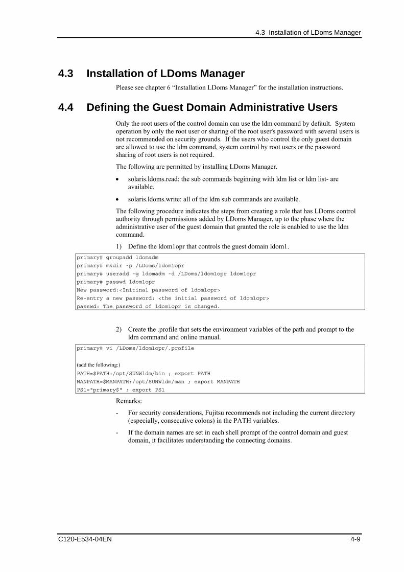
4.3 Installation of LDoms Manager
4.3 Installation of LDoms Manager Please see chapter 6 “Installation LDoms Manager” for the installation instructions.
4.4 Defining the Guest Domain Administrative Users Only the root users of the control domain can use the ldm command by default. System operation by only the root user or sharing of the root user's password with several users is not recommended on security grounds. If the users who control the only guest domain are allowed to use the ldm command, system control by root users or the password sharing of root users is not required.
The following are permitted by installing LDoms Manager.
• solaris.ldoms.read: the sub commands beginning with ldm list or ldm list- are available.
• solaris.ldoms.write: all of the ldm sub commands are available.
The following procedure indicates the steps from creating a role that has LDoms control authority through permissions added by LDoms Manager, up to the phase where the administrative user of the guest domain that granted the role is enabled to use the ldm command.
1) Define the ldom1opr that controls the guest domain ldom1. primary# groupadd ldomadm
primary# mkdir -p /LDoms/ldom1opr
primary# useradd -g ldomadm -d /LDoms/ldom1opr ldom1opr
primary# passwd ldom1opr
New password:<Initinal password of ldom1opr>
Re-entry a new password: <the initial password of ldom1opr>
passwd: The password of ldom1opr is changed.
2) Create the .profile that sets the environment variables of the path and prompt to the ldm command and online manual.
primary# vi /LDoms/ldom1opr/.profile
(add the following:) PATH=$PATH:/opt/SUNWldm/bin ; export PATH
MANPATH=$MANPATH:/opt/SUNWldm/man ; export MANPATH
PS1="primary$" ; export PS1
Remarks:
- For security considerations, Fujitsu recommends not including the current directory (especially, consecutive colons) in the PATH variables.
- If the domain names are set in each shell prompt of the control domain and guest domain, it facilitates understanding the connecting domains.
C120-E534-04EN 4-9
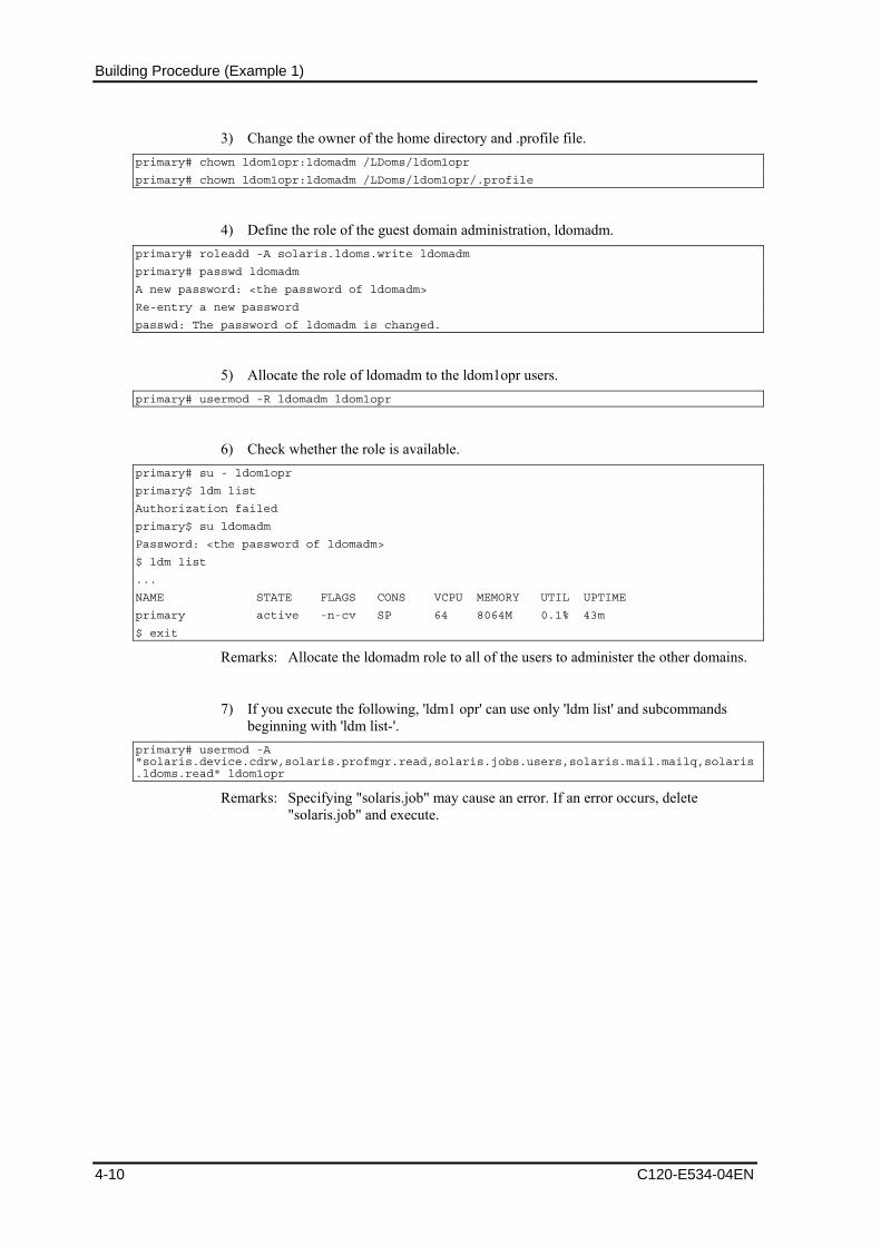
Building Procedure (Example 1)
3) Change the owner of the home directory and .profile file. primary# chown ldom1opr:ldomadm /LDoms/ldom1opr
primary# chown ldom1opr:ldomadm /LDoms/ldom1opr/.profile
4) Define the role of the guest domain administration, ldomadm. primary# roleadd -A solaris.ldoms.write ldomadm
primary# passwd ldomadm
A new password: <the password of ldomadm>
Re-entry a new password
passwd: The password of ldomadm is changed.
5) Allocate the role of ldomadm to the ldom1opr users. primary# usermod -R ldomadm ldom1opr
6) Check whether the role is available. primary# su - ldom1opr
primary$ ldm list
Authorization failed
primary$ su ldomadm
Password: <the password of ldomadm>
$ ldm list
...
NAME STATE FLAGS CONS VCPU MEMORY UTIL UPTIME
primary active -n-cv SP 64 8064M 0.1% 43m
$ exit
Remarks: Allocate the ldomadm role to all of the users to administer the other domains.
7) If you execute the following, 'ldm1 opr' can use only 'ldm list' and subcommands beginning with 'ldm list-'.
primary# usermod -A "solaris.device.cdrw,solaris.profmgr.read,solaris.jobs.users,solaris.mail.mailq,solaris.ldoms.read" ldom1opr
Remarks: Specifying "solaris.job" may cause an error. If an error occurs, delete "solaris.job" and execute.
4-10 C120-E534-04EN

4.4 Defining the Guest Domain Administrative Users
8) The following table indicates the relationship between the user’s names/roles names on the definition or control domain and executable functions.
Usable functions root user
(Permission : Solaris.*)
ldomadm role
(solaris.ldoms.write)
ldom?opr
(Permission: when Solaris or ldoms.read
is provided
ldm list , ldm list-*** A A A
ldm bind-domain A A N/A
ldm add-*** A A N/A
ldm remove-*** A A N/A
ldm set-*** A A N/A
ldm start-domain A A N/A
ldm stop-domain A A N/A
ldm unbind-domain A A N/A
ldm panic-domain A A N/A
Shutdown of the control domain, etc
A N/A N/A
C120-E534-04EN 4-11
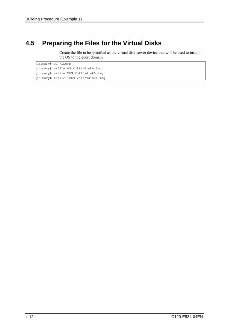
Building Procedure (Example 1)
4.5 Preparing the Files for the Virtual Disks Create the file to be specified as the virtual disk server device that will be used to install the OS to the guest domain.
primary# cd /LDoms
primary# mkfile 8G Vol1/vdisk0.img
primary# mkfile 20G Vol2/vdisk0.img
primary# mkfile 100G Vol3/vdisk0.img
4-12 C120-E534-04EN

4.6 Building the Control Domain
4.6 Building the Control Domain
4.6.1 Executing the control domain construction script Build the control domain by executing the control domain construction script which was created in advance.
Check the configuration, which is stored in the system controller after executing the control domain construction script.
primary# . /LDoms/Scripts/primary.sh
...
primary# ldm list-config
factory-default
initial[next poweron]
Remarks: The above indicates that the LDoms configuration is the factory set configuration, which is set to be changed after reboot .
Start the server daemon of the virtual network terminal. primary# svcs -a |grep ldom
disabled 17:01:10 svc:/ldoms/vntsd:default
online 16:10:48 svc:/ldoms/ldmd:default
primary# svcadm enable svc:/ldoms/vntsd:default
primary# svcs svc:/ldoms/vntsd:default
STATE STIME FMRI
online 17:03:10 svc:/ldoms/vntsd:default
4.6.2 Rebooting the control domain The system configuration is changed after the system is powered off and then powered on again.
primary# shutdown -i0 -g0 -y
:
syncing file systems... done
{0} ok power-off
:
Chassis | critical: Host has been powered off
[Input #(sharp) + .(dot)]
The following operation differs depending on the system monitoring mechanisms (ALOM, ILOM).
Follow the procedure for your system monitoring mechanism.
【ALOM】 sc> poweron -c
Enter #. to return to ALOM.
Chassis | major: Host has been powered on
C120-E534-04EN 4-13

Building Procedure (Example 1)
【ILOM】 -> start /SYS Are you sure you want to start SyS (y/n)? y Starting /SYS P2LE52 console login: Apr 17 13:13:17 P2LE52 unix: WARNING: Power-off requested, system will now shutdown.
:
:
:
P2LE52 console login:
4.6.3 Checking the control domain configuration Check the control domain configuration after the reboot.
primary# ldm ls-config
factory-default
initial [current]
primary# ldm list-bindings primary
NAME STATE FLAGS CONS VCPU MEMORY UTIL UPTIME
primary active -n-cv SP 8 1G 0.4% 10m
MAC
00:14:4f:46:41:a0
VCPU
VID PID UTIL STRAND
0 0 2.2% 100%
1 1 0.2% 100%
2 2 0.0% 100%
3 3 0.0% 100%
4 4 0.9% 100%
5 5 0.1% 100%
6 6 0.1% 100%
7 7 0.0% 100%
MEMORY
RA PA SIZE
0x8000000 0x8000000 1G
IO
DEVICE PSEUDONYM OPTIONS
pci@0 pci
niu@80 niu
VDS
NAME VOLUME OPTIONS DEVICE
primary-vds0 vol1 /LDoms/Vol1/vdisk0.img
vol2 /LDoms/Vol2/vdisk0.img
vol3 /LDoms/Vol3/vdisk0.img
VSW
NAME MAC NET-DEV DEVICE MODE
primary-vsw0 00:14:4f:f8:97:91 e1000g0 switch@0 prog,promisc
4-14 C120-E534-04EN
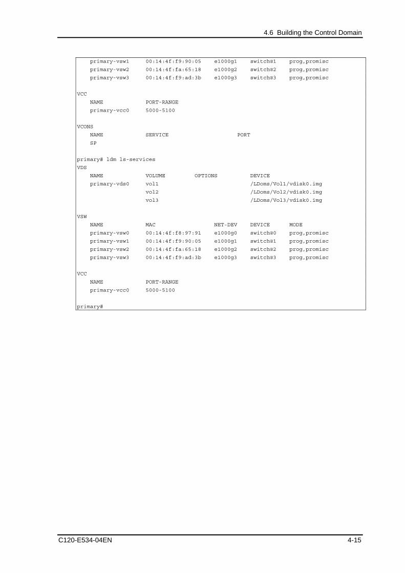
4.6 Building the Control Domain
primary-vsw1 00:14:4f:f9:90:05 e1000g1 switch@1 prog,promisc
primary-vsw2 00:14:4f:fa:65:18 e1000g2 switch@2 prog,promisc
primary-vsw3 00:14:4f:f9:ad:3b e1000g3 switch@3 prog,promisc
VCC
NAME PORT-RANGE
primary-vcc0 5000-5100
VCONS
NAME SERVICE PORT
SP
primary# ldm ls-services
VDS
NAME VOLUME OPTIONS DEVICE
primary-vds0 vol1 /LDoms/Vol1/vdisk0.img
vol2 /LDoms/Vol2/vdisk0.img
vol3 /LDoms/Vol3/vdisk0.img
VSW
NAME MAC NET-DEV DEVICE MODE
primary-vsw0 00:14:4f:f8:97:91 e1000g0 switch@0 prog,promisc
primary-vsw1 00:14:4f:f9:90:05 e1000g1 switch@1 prog,promisc
primary-vsw2 00:14:4f:fa:65:18 e1000g2 switch@2 prog,promisc
primary-vsw3 00:14:4f:f9:ad:3b e1000g3 switch@3 prog,promisc
VCC
NAME PORT-RANGE
primary-vcc0 5000-5100
primary#
C120-E534-04EN 4-15

Building Procedure (Example 1)
4-16 C120-E534-04EN
4.7 Building the Guest Domain
4.7.1 Executing the guest domain construction script Execute the guest domain construction script, which was created in advance and then build the guest domain.
Check the state of the guest domain after executing the guest domain construction script. primary$ . /LDoms/Scripts/ldom1.sh
...
primary$ ldm list-bindings ldom1
NAME STATE FLAGS CONS VCPU MEMORY UTIL UPTIME
ldom1 active -t--- 5001 16 1920M 6.2% 2m
MAC
00:14:4f:fb:84:ad
VCPU
VID PID UTIL STRAND
0 8 100% 100%
1 9 0.0% 100%
2 10 0.0% 100%
3 11 0.0% 100%
4 12 0.0% 100%
5 13 0.0% 100%
6 14 0.0% 100%
7 15 0.0% 100%
8 16 0.0% 100%
9 17 0.0% 100%
10 18 0.0% 100%
11 19 0.0% 100%
12 20 0.0% 100%
13 21 0.0% 100%
14 22 0.0% 100%
15 23 0.0% 100%
MEMORY
RA PA SIZE
0x8000000 0x48000000 1920M
VARIABLES
auto-boot?=false
NETWORK
NAME SERVICE DEVICE MAC
vnet0 primary-vsw0@primary network@0 00:14:4f:f8:b4:8c
PEER MAC
primary-vsw0@primary 00:14:4f:f8:97:91
NAME SERVICE DEVICE MAC
vnet1 primary-vsw1@primary network@1 00:14:4f:f8:dd:13
PEER MAC
primary-vsw1@primary 00:14:4f:f9:90:05
DISK

4.7 Building the Guest Domain
C120-E534-04EN 4-17
NAME VOLUME TOUT DEVICE SERVER
vdisk0 vol1@primary-vds0 disk@0 primary
VCONS
NAME SERVICE PORT
ldom1 primary-vcc0@primary 5001
$ . /LDoms/Scripts/ldom2.sh
...
$ . /LDoms/Scripts/ldom3.sh
...
Remarks:
ove FLAGS indicates that the domain is the transition state (mainly, ok
- ntrol domain is not required to make additions to, changes to, and
- e a directory to be used to save the domain configuration
- The abprompt mode).
Rebooting the codeletions from the guest domain without making any changes to the control domain configuration.
You need to creatinformation before executing the guest domain configuration script.

Building Procedure (Example 1)
4.7.2 Checking the guest domain console Check whether you can access the guest domain console by using the virtual console.
After the connection, you can check the virtual environment by using the OBP command. primary# svcadm enable svc:/ldoms/vntsd:default
primary# telnet localhost 5001
Trying 127.0.0.1...
Connected to localhost.
Escape character is '^]'.
Connecting to console "ldom1" in group "ldom1" ....
Press ~? for control options ..
{0} ok banner
SPARC Enterprise T5120, No Keyboard
Copyright 2007 Sun Microsystems, Inc. All rights reserved.
OpenBoot 4.27.10, 1920 MB memory available, Serial #66815149.
Ethernet address 0:14:4f:fb:84:ad, Host ID: 83fb84ad.
{0} ok devalias
vdisk0 /virtual-devices@100/channel-devices@200/disk@0
vnet1 /virtual-devices@100/channel-devices@200/network@1
vnet0 /virtual-devices@100/channel-devices@200/network@0
net /virtual-devices@100/channel-devices@200/network@0
disk /virtual-devices@100/channel-devices@200/disk@0
virtual-console /virtual-devices/console@1
name aliases
{0} ok show-devs
/cpu@f
/cpu@e
/cpu@d
/cpu@c
/cpu@b
/cpu@a
/cpu@9
/cpu@8
/cpu@7
/cpu@6
/cpu@5
/cpu@4
/cpu@3
/cpu@2
/cpu@1
/cpu@0
/virtual-devices@100
/virtual-memory
/memory@m0,8000000
/aliases
/options
/openprom
More [<space>,<cr>,q,n,p,c] ?
4-18 C120-E534-04EN

4.7 Building the Guest Domain
Remarks:
- When returning to the control domain, enter [~(tilde)] and [. (dot)] sequentially. In the case of connecting to the control domain with ssh, the connection to the control domain is disconnected using this operation. If you do not want to disconnect from the control domain, enter the [.] after entering the [~ (tilde)] + [~ (tilde)] + [. (dot)] and a number of [~] equivalent to the layer that uses ssh + 1.
- When sending the break signal, enter [~(tilde)] and [#(sharp)] sequentially.
- The MAC address that is indicated by the above banner command, has no relationship to the virtual network device (vnet0, vnet1). Check the MAC address of the virtual network device by outputting the ldm list-bindings command.
C120-E534-04EN 4-19
Building Procedure (Example 1)
4.8 Retaining the LDoms Configuration Information The hypervisor reads the LDoms configuration stored in EEPROM at the time of power activation. The LDoms configuration may be lost as a result of a failure of hardware, which includes EEPROM, such as a motherboard.
The LDoms Manager starts the guest domain by referring to the LDoms configuration which has been stored on the disk (/var/opt/SUNWldm/). If this disk cannot be accessed, the guest domain will not start the guest domain.
The following corrective actions are recommended for these conditions.
• Save of the construction script
Save the construction script in a certain location (/LDoms/Scripts/ in this document) so that the latest control domain construction script (primary.sh in this document) or guest domain construction script (ldom?.sh in this document) can be executed as required, and so that the LDoms environment can be rebuilt.
• Collection/Save of the guest domain configuration information
The outputs of ldm list-constraints -x [domain-name] when used for the input of ldm add-domain -i [file-name], can rebuild the collected guest domain. Collect the configuration information of the guest domain whenever the configuration is changed and save it in a certain location (/LDoms/Domains/ in this document).
• Save of the information to external media
Copy the information in the CD-R, DVD-R, tapes or file servers to be prepared in case they are lost from the disk.
4-20 C120-E534-04EN

4.9 Installing the Guest domain
4.9 Installing the Guest domain The OS installation of the guest domain is executed using the network installation method as well as the standard OS. Fujitsu recommends preparing another chassis for the installation server. The cancellation of the SST security configuration and the setting for virtual network communication between the control domain and guest domain are required although it is possible to use the control domain as the installation server.
4.9.1 Making the settings to the installed server 1) Check the MAC address (Ethernet) of the guest domain (ldom1 in the following
example). (Operation of control domain) primary$ ldm ls -l ldom1 <Enter>
: NETWORK
NAME SERVICE DEVICE MAC
vnet0 primary-vsw0@primary network@0 <MAC address of the guest domain>
Remarks: DO NOT USE the result displayed by the banner command of the guest domain OBP.
2) Register the MAC address, IP address and host name of the guest domain with the installation server. (Operation of installed server)
# vi /etc/ethers <Enter>
(Add the following) <MAC address of the guest domain> ldom1
...
# vi /etc/hosts <Enter>
(Add the following) 192.168.1.101 ldom1
...
3) Set the installation client. (Operation of installed server)
Remarks: Create the Solaris install image of the installation server in advance. # cd <path to the Solaris image>/Solaris_10/Tools <Enter>
# ./add_install_client -e <MAC address of the guest domain> ldom1 sun4v <Enter>
4) Confirm the setting. (Operation of installed server) # cat /etc/bootparams <Enter>
ldom1 root=192.168.1.100:/export/image/solaris10_8_07/Solaris_10/Tools/
Bootinstall=192.168.1.100:/export/image/solaris10_8_07/ boottype=:in rootopts=:rsize=8192
5) Share the install image. (Operation of installed server.)
Remarks: It is not necessary to execute the command when sharing has already been done.
# share -o ro,anon=0 /export/image <Enter>
C120-E534-04EN 4-21

Building Procedure (Example 1)
4.9.2 Installing the network 1) Connect to the console of the guest domain. (Operation of control domain)
primary$ telnet localhost 5001 <Enter>
2) Check the virtual network device. (Operation of guest domain) {0} ok devalias <Enter>
vdisk0 /virtual-devices@100/channel-devices@200/disk@0
vnet1 /virtual-devices@100/channel-devices@200/network@1
vnet0 /virtual-devices@100/channel-devices@200/network@0
net /virtual-devices@100/channel-devices@200/network@0
disk /virtual-devices@100/channel-devices@200/disk@0
virtual-console /virtual-devices/console@1
name aliases
{0} ok
Remarks: The devices indicated with other net or disk names are not available in a guest domain other than the I/O domain.
3) Execute network installation. (Operation of guest domain) {0} ok boot vnet0 <Enter>
Boot device: /virtual-devices@100/channel-devices@200/network@0 File and args:
:
SunOS Release 5.10 Version Generic_120011-14 64-bit
Copyright 1983-2007 Sun Microsystems, Inc. All rights reserved.Use is subject to license terms.
:
whoami: no domain name
Configuring devices.
Using RPC Bootparams for network configuration information.
Attempting to configure interface vnet0...
Configured interface vnet0
Beginning system identification...
Searching for configuration file(s)...
Search complete.
Discovering additional network configuration...
Remarks:
- After this, execute the standard OS installation.
- The virtual disk names (c0d0s0, etc) are displayed as the disk name in the guest domain.
- The virtual network device names (vnet0, etc) are displayed as the network device name in the guest domain.
- If the virtual console is disconnected during the installation, the screen cannot be displayed normally even if reconnecting. Avoid disconnecting the virtual console during the installation.
4-22 C120-E534-04EN

4.9 Installing the Guest domain
C120-E534-04EN 4-23
4.9.3 Installing from DVD DVD boot of the guest domain is possible in LDoms Manager 1.0.3 or later.
4.9.4 Installing Enhanced Support Facility (ESF) Install ESF by referring to the following document.
• [Enhanced Support Facility Online Manual] and [Enhanced Support Facility 3.1 installation guide]
http://software.fujitsu.com/jp/manual/manualindex/P08001214e.html
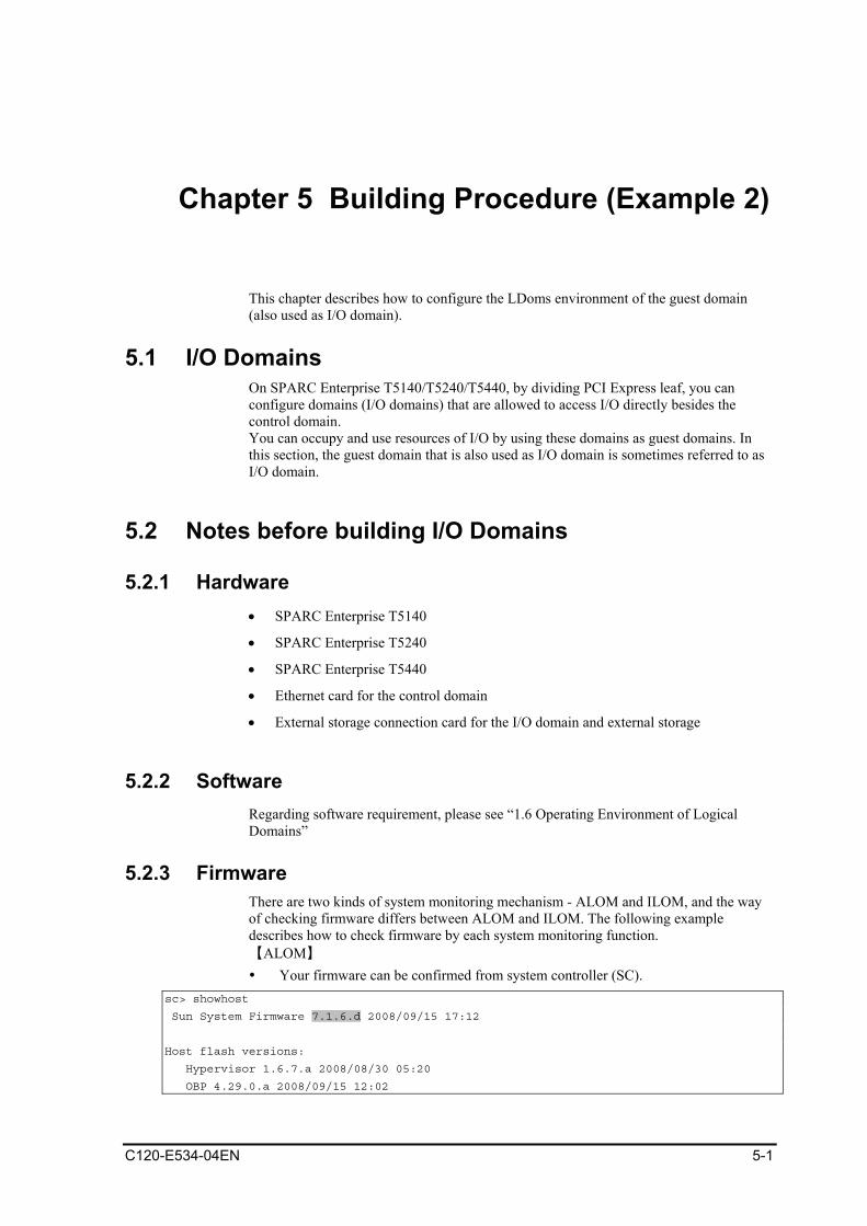
Chapter 5 Building Procedure (Example 2)
This chapter describes how to configure the LDoms environment of the guest domain (also used as I/O domain).
5.1 I/O Domains On SPARC Enterprise T5140/T5240/T5440, by dividing PCI Express leaf, you can configure domains (I/O domains) that are allowed to access I/O directly besides the control domain. You can occupy and use resources of I/O by using these domains as guest domains. In this section, the guest domain that is also used as I/O domain is sometimes referred to as I/O domain.
5.2 Notes before building I/O Domains
5.2.1 Hardware • SPARC Enterprise T5140
• SPARC Enterprise T5240
• SPARC Enterprise T5440
• Ethernet card for the control domain
• External storage connection card for the I/O domain and external storage
5.2.2 Software Regarding software requirement, please see “1.6 Operating Environment of Logical Domains”
5.2.3 Firmware There are two kinds of system monitoring mechanism - ALOM and ILOM, and the way of checking firmware differs between ALOM and ILOM. The following example describes how to check firmware by each system monitoring function. 【ALOM】 Your firmware can be confirmed from system controller (SC).
sc> showhost
Sun System Firmware 7.1.6.d 2008/09/15 17:12
Host flash versions:
Hypervisor 1.6.7.a 2008/08/30 05:20
OBP 4.29.0.a 2008/09/15 12:02
C120-E534-04EN 5-1

Building Procedure (Example 2)
5-2 C120-E534-04EN
POST 4.29.0.a 2008/09/15 12:29
sc>
Remarks: The screenshots in Section 5.2.3 show examples of CLI operations of the system controller in the ALOM CMT shell as well as the execution results. Refer to [Integrated Lights Out Manager Additional Manual] about ALOM CMT shell.
【ILOM】 -> show /HOST /HOST Targets: bootmode diag domain Properties: autorestart = reset autorunonerror = false bootfailrecovery = poweroff bootrestart = none boottimeout = 0 hypervisor_version = Hypervisor 1.7.0 2008/12/11 13:40 macaddress = 00:14:4f:46:e8:12 maxbootfail = 3 obp_version = OBP 4.30.0 2008/12/11 12:16 post_version = POST 4.30.0 2008/12/11 12:44 send_break_action = (none) status = Solaris running sysfw_version = Sun System Firmware 7.2.0 2008/12/11 17:58 Commands: cd set show
5.2.4 Loading additional cards Regarding slots implementing Ethernet cards, XAUI cards, storage connection cards, and other cards on SPARC Enterprise T5140/T5240, please see "Figure 5.1".
Control Domain : pci@400
I/O Domain : pci@500
Slot #0 PCI-E :pci@500 XAUI :pci@500
Slot #1 PCI-E :pci@400 XAUI :pci@500
Slot #2 PCI-E :pci@400
T5240 only
Slot #3 PCI-E :pci@400
Slot #4 PCI-E :pci@500
Slot #5 PCI-E :pci@500

5.3 Building Procedure
C120-E534-04EN 5-3
Figure 5.1 Slot location and I/O devices on SPARC Enterprise T5140/T5240
Regarding slots for an Ethernet card, XAUI card, Storage connection card, and other cards on SPARC Enterprise T5440, please refer to Figure 5.2.
In addition, I/O device and the number of I/O domains that you can create are different between 2 CPU model and 4 CPU model..
(In case of 2 CPU model)
Number of I/O Domains : 2
Control Domain : pci@400
I/O Domain : pci@500
(In case of 4 CPU model)
Number of I/O Domains : 4
Control Domain : pci@400(*), pci@500, pci@600, pci@700
I/O Domain : pci@500, pci@600, pci@700
(*) Be sure to allocate pci@400 to the control domain.
4CPU
2CPU pci@400
pci@400 pci@600 pci@500 pci@700
pci@500
Slot
0
Slot
1
Slot
2
Slot
3
Slot
4 /
XA
UI 0
On Board LAN Sl
ot 6
Slot
7
USB
HDD
DVD
Slot
5 /
XA
UI 1
Figure 5.2 Slot location and I/O devices on SPARC Enterprise T5440
dure of building LDoms, and determination of LDoms
you create the control domain, or to the guest domain also used as I/O domain on disks
the steps of building LDoms system.
are resources
5.3 Building Procedure This section describes the proceconfiguration that you can make before starting the configuration, and preparation of LDoms system configuration script. Ifconnected by using Fujitsu option, you must have an installation server.
5.3.1 Building Procedure The following describes
1) Determining the LDoms configuration
2) Creating the allocation sheet for hardw

Building Procedure (Example 2)
5-4 C120-E534-04EN
3) Preparing the LDoms configuration scripts
4) Upgrading firmware
5) Installing the OS for the control domain
e LDoms administrative user
ch on/off)
uding switch on/off)
information
information at the final state.
5.3.2 Determining the LDoms configuration the hardware resources allocated
as ‘split-io’, 'initial', ‘initial-io’, or ‘operation’ in this
2) es
ds that the number of the domain operated in LDoms be less than
ains are configured as shown below.
Domain) : iodom
3)
h isk server (primary-vds0) can operate on the control
The virtual disk server The virtual disk server device for ldom1 (vol1) →
6) Installing LDoms Manager and defining th
7) Preparing the files for the virtual disks
8) Uninstalling pci devices (including swit
9) Building the control domain ( including switch on/off)
10) Building the guest domain (also used as I/O domain) (incl
11) Building the guest domain
12) Retaining the configuration
13) Installing the guest domain
14) Saving LDoms configuration
The domains to be constructed, the virtual services and to each domain are configured.
1) LDoms configuration name
The configuration is specified document.
Domain nam
Fujitsu recommenthe number of CPU cores.
In this document, four dom
Control Domain : primary
Guest Domain(also used as I/O
Guest Domain : ldom1, ldom2
The virtual disk service
In t is document, the virtual ddomain only, and the three virtual disk devices, vol1, vol2 and vol3, are allocated toldom1, ldom2, and ldom3, respectively as virtual disks (vdisk0).
(primary-vds0) The virtual disk for ldom1 (vdisk0)
The virtual disk server device for ldom2 (vol2) → The virtual disk for ldom2 (vdisk0)
You can specify a general file in the UFS file system as a virtual disk device. You can
/LDoms Vol
allocate the file on the following directory structure as the virtual disk server device.
1 vdisk0.img → vol1 Virtual disk server device entities
Vol2 vdisk0.img → vol2 Virtual disk server device entities
Scripts → Storage directory of the cosntruction script
Domains → Storage directory of the configuration information for the guest domain
4) The virtual switch service

5.3 Building Procedure
C120-E534-04EN 5-5
The virtual switch service (primary-vsw0, primary-vsw1) can operate on the control
f
Network adapter (fjgi0) - Virtual switch (primary-vsw0) - Used for the communication
domain, and the network adapter (fjgi0) is used by all domains. The virtual switch is allocated for each of ldom1, and ldom2 to function as the dedicated network adapter othe virtual network device (vnet1). I/O domain will be connected with the control domain , and guest domain via network switch.
among all of domains (vnet0)
Network adapter (fjgi1) - Virtual switch (primary-vsw1) - Used in ldom1 and ldom2 (vnet1)
Network adapter (nxge0) - same network as Control Domain(fjgi0 vsw0) each Guest Domain(vnet0)
Network adapter (nxge1) - same network for WAN as Control Domain(fjgi1 vsw1) each Guest Domain(vnet1)
5) Distributing device service of the virtual console terminal
5002 are allocated for
5.3.3 Creating the allocation sheet for hardware resources
In this document, the dedicated port numbers from 5000 toeach virtual console of iodom, ldom1, and ldom2.
The following allocation sheet for the hardware resources is created.

Building Procedure (Example 2)
5-6 C120-E534-04EN
Figure 5.3 Example of configuration on SPARC Enterprise T5140
SPARC Enterprise T5140 Number of CPU : 96 threads Memory : 32GB (Available : 32544 MB)
primary vcpu : 16 mem : 4G mau : 0
iodom vcpu : 32
mem : 8G mau : 0
vds primary-vds0
HDD HDD
pci@500
vws : NET0 primary-vsw0
HDD
Slot#0
Added HBA
OnBoard LAN
NET0 NET1
pci@400
On Board SAS Chip
Slot#2
Installation Server / Console NET
Added NIC NET0 NET1
vcc primary-vcc0
ldom1 vcpu : 24
mem : 8G mau : 0
vnet0 vnet1
vol1
vol2
vdisk0
WAN
vcons:5001
vws : NET1 primary-vsw1 vcons:5000
ldom2 vcpu : 24
mem : 8G mau : 0
vnet0 vnet1vdisk0
vcons:5002
5000-5100
HDD
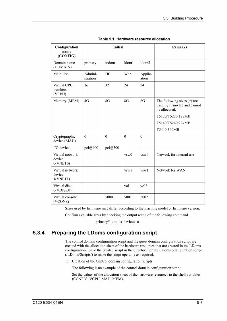
5.3 Building Procedure
Table 5.1 Hardware resource allocation
Configuration name
(CONFIG)
Initial Remarks
Domain name (DOMAIN)
primary iodom ldom1 ldom2
Main Use Admini-stration
DB Web Applic-ation
Virtual CPU numbers (VCPU)
16 32 24 24
Memory (MEM) 4G 8G 8G 8G The following sizes (*) are used by firmware and cannot be allocated.
T5120/T5220:128MB
T5140/T5240:224MB
T5440:340MB
Cryptographic device (MAU)
0 0 0 0
I/O device pci@400 pci@500
Virtual network device 0(VNET0)
vsw0 vsw0 Network for internal use
Virtual network device 1(VNET1)
vsw1 vsw1 Network for WAN
Virtual disk 0(VDISK0)
vol1 vol2
Virtual console (VCONS)
5000 5001 5002
Sizes used by firmware may differ according to the machine model or firmware version.
Confirm available sizes by checking the output result of the following command.
primary# ldm list-devices -a
5.3.4 Preparing the LDoms configuration script The control domain configuration script and the guest domain configuration script are created with the allocation sheet of the hardware resources that are created in the LDoms configuration. Save the created script in the directory for the LDoms configuration script (/LDoms/Scripts/) to make the script operable as required.
1) Creation of the Control domain configuration scripts
The following is an example of the control domain configuration script.
Set the values of the allocation sheet of the hardware resources to the shell variables (CONFIG, VCPU, MAU, MEM).
C120-E534-04EN 5-7

Building Procedure (Example 2)
#!/bin/sh
# Control domain configuration script (for 4 domains)
CONFIG=initial # Configuration name to store in the system controller
VCPU=16 # Virtual CPU numbers to allocate to the control domain
MAU=0 # MAU numbers to allocat to the control domain
MEM=4G # Memory to allocate to the control domain (K:KB,M:MB,G:GB)
ldm set-mau $MAU primary
ldm set-vcpu $VCPU primary
ldm set-memory $MEM primary
# Define the virtual disk server.
ldm add-vdiskserver primary-vds0 primary
# Define the virtual disk server device and specify the entity.
ldm add-vdiskserverdevice /LDoms/Vol1/vdisk0.img vol1@primary-vds0
ldm add-vdiskserverdevice /LDoms/Vol2/vdisk0.img vol2@primary-vds0
# Define the virtual switch service and specify the network adapter. (*)
ldm add-vswitch net-dev=fjgi0 primary-vsw0 primary
ldm add-vswitch net-dev=fjgi1 primary-vsw1 primary
# Specify the distributing device service of the virtual console terminal and the port range to allocate.
ldm add-vconscon port-range=5000-5100 primary-vcc0 primary
# Save the configuration in the system controller.
ldm add-config $CONFIG
eeprom auto-boot\?=false
# After executing this script, the power-off, reclosing or reset is required.
* If you configure the I/O domain, please specify the driver name of LAN card added to
PCIe Slot1 or Slot2 (or Slot3 if your machine is T5140).
This script is stored in the /LDoms/Scripts/ directory of the control domain under the name of primary.sh.
5-8 C120-E534-04EN

5.3 Building Procedure
2) Creating the I/O domain configuration script
The following is an example of the I/O domain configuration script. Set the values on the 'Hardware resource allocation' sheet to the shell variables (DOMAIN,VCPU,MAU,MEM,VCONS, IO).
#!/bin/sh # IO domain configuration script DOMAIN=iodom # Domain name VCPU=32 # CPU numbers to allocate to the domain MAU=0 # MAU numbers to allocate the domains MEM=8G # Memory to allocate the domain (K:KB,M:MB,G:GB) VCONS=”port=5000” IO=”pci@500” # PCI device to be allocated to the domain ldm add-domain $DOMAIN ldm set-mau $MAU $DOMAIN ldm add-vcpu $VCPU $DOMAIN ldm add-memory $MEM $DOMAIN # Do not alloate vnet, vdisk in order to use resources on the PCI device ldm add-io $IO $DOMAIN ldm set-vcons $VCONS $DOMAIN # Specify the domain to prevent the automatic disk boot when starting the domains because of the network installation. ldm set-variable auto-boot\?=false $DOMAIN # When executing the following, the configuration information of the domain is saved. # The stored configuration information is available as the input of the following command. # ldm add-domain –i ldm list-constraints -x $DOMAIN >/LDoms/Domains/$DOMAIN.xml cp /LDoms/Domains/$DOMAIN.xml /LDoms/$DOMAIN.`date +%y%m%d%H%M%S` # When executing the following, the Ethernet address of the virtual network of the domain is indicated. # The Ethernet address which is displayed in the ok prompt is not the virtual network device address. ldm ls -e $DOMAIN|grep vnet|cut -d@ -f3| nawk '{ print $1,$2 }' | xargs -L 1 echo vnet
If you want to use a hosted of I/O domain permanently, please change the setting as described below.
Example) Set hosted to “83fc0000” MAC="00:14:4F:FC:00:00" #Addition ldm add-domain mac-addr=$MAC $DOMAIN #Change
This script is stored in the /LDoms/Scripts/ directory of the control domain under the name of iodom.sh .
C120-E534-04EN 5-9
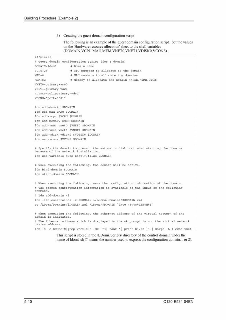
Building Procedure (Example 2)
3) Creating the guest domain configuration script
The following is an example of the guest domain configuration script. Set the values on the 'Hardware resource allocation' sheet to the shell variables (DOMAIN,VCPU,MAU,MEM,VNET0,VNET1,VDISK0,VCONS).
#!/bin/sh
# Guest domain configuration script (for 1 domain)
DOMAIN=ldom1 # Domain name
VCPU=24 # CPU numbers to allocate to the domain
MAU=0 # MAU numbers to allocate the domains
MEM=8G # Memory to allocate the domain (K:KB,M:MB,G:GB)
VNET0=primary-vsw0
VNET1=primary-vsw1
VDISK0=vol1@primary-vds0
VCONS="port=5001"
ldm add-domain $DOMAIN
ldm set-mau $MAU $DOMAIN
ldm add-vcpu $VCPU $DOMAIN
ldm add-memory $MEM $DOMAIN
ldm add-vnet vnet0 $VNET0 $DOMAIN
ldm add-vnet vnet1 $VNET1 $DOMAIN
ldm add-vdisk vdisk0 $VDISK0 $DOMAIN
ldm set-vcons $VCONS $DOMAIN
# Specify the domain to prevent the automatic disk boot when starting the domains because of the network installation.
ldm set-variable auto-boot\?=false $DOMAIN
# When executing the following, the domain will be active.
ldm bind-domain $DOMAIN
ldm start-domain $DOMAIN
# When executing the following, save the configuration information of the domain.
# The stored configuration information is available as the input of the following command.
# ldm add-domain -i
ldm list-constraints -x $DOMAIN >/LDoms/Domains/$DOMAIN.xml
cp /LDoms/Domains/$DOMAIN.xml /LDoms/$DOMAIN.`date +%y%m%d%H%M%S`
# When executing the following, the Ethernet address of the virtual network of the domain is indicated.
# The Ethernet address which is displayed in the ok prompt is not the virtual network device address.
ldm ls -e $DOMAIN|grep vnet|cut -d@ -f3| nawk '{ print $1,$2 }' | xargs -L 1 echo vnet
This script is stored in the /LDoms/Scripts/ directory of the control domain under the name of ldom?.sh (? means the number used to express the configuration domain:1 or 2).
5-10 C120-E534-04EN

5.4 Building an Installation Server
5.4 Building an Installation Server Please see product manuals for each driver to build an installation server.
Latest Drivers
http://www.fujitsu.com/global/support/computing/server/unix/driver/
FUJITSU PCI GigabitEthernet 3.0
http://www.fujitsu.com/global/services/computing/server/sparcenterprise/downloads/driver/giga-3/
Installation Server Configuration Guide For I/O Device Drivers
FUJITSU ULTRA LVD SCSI Host Bus Adapter Driver
http://www.fujitsu.com/global/services/computing/server/sparcenterprise/downloads/driver/ultra320-scsi-2/
Installation Server Configuration Guide For I/O Device Drivers
FUJITSU PCI Fibre Channel 4.0
http://www.fujitsu.com/global/services/computing/server/sparcenterprise/downloads/driver/pfca-4/
FUJITSU PCI Fibre Channel 4.0 Update1 Instructions
C120-E534-04EN 5-11

Building Procedure (Example 2)
5.5 Installation of LDoms Manager Please see chapter 6 “Installation of LDoms Manager” for the installation instructions.
5.6 Defining the Guest Domain Administrative Users Only the root users of the control domain can use the ldm command by default. System operation by only the root user or sharing of the root user's password with several users is not recommended on security grounds. If the users who control the only guest domain are allowed to use the ldm command, system control by root users or the password sharing of root users is not required.
The following are permitted by installing LDoms Manager.
• solaris.ldoms.read: the sub commands beginning with ldm list or ldm list- are available.
• solaris.ldoms.write: all of the ldm sub commands are available.
The following procedure indicates the steps from creating a role that has LDoms control authority through permissions added by LDoms Manager, up to the phase where the administrative user of the guest domain that granted the role is enabled to use the ldm command.
1) Define the ldom1opr that controls the guest domain ldom1. primary# groupadd ldomadm
primary# mkdir -p /LDoms/ldom1opr
primary# useradd -g ldomadm -d /LDoms/ldom1opr ldom1opr
primary# passwd ldom1opr
New password:<Initinal password of ldom1opr>
Re-entry a new password: <the initial password of ldom1opr>
passwd: The password of ldom1opr is changed.
2) Create the .profile that sets the environment variables of the path and prompt to the ldm command and online manual.
primary# vi /LDoms/ldom1opr/.profile
(add the following:) PATH=$PATH:/opt/SUNWldm/bin ; export PATH
MANPATH=$MANPATH:/opt/SUNWldm/man ; export MANPATH
PS1="primary$" ; export PS1
Remarks:
- For security considerations, Fujitsu recommends not including the current directory (especially, consecutive colons) in the PATH variables.
- If the domain names are set in each shell prompt of the control domain and guest domain, it facilitates understanding the connecting domains.
3) Change the owner of the home directory and .profile file. primary# chown ldom1opr:ldomadm /LDoms/ldom1opr
primary# chown ldom1opr:ldomadm /LDoms/ldom1opr/.profile
5-12 C120-E534-04EN

5.6 Defining the Guest Domain Administrative Users
4) Define the role of the guest domain administration, ldomadm. primary# roleadd -A solaris.ldoms.write ldomadm
primary# passwd ldomadm
A new password: <the password of ldomadm>
Re-entry a new password
passwd: The password of ldomadm is changed.
5) Allocate the role of ldomadm to the ldom1opr users. primary# usermod -R ldomadm ldom1opr
6) Check whether the role is available. primary# su - ldom1opr
primary$ ldm list
Authorization failed
primary$ su ldomadm
Password: <the password of ldomadm>
$ ldm list
...
NAME STATE FLAGS CONS VCPU MEMORY UTIL UPTIME
primary active -n-cv SP 64 8064M 0.1% 43m
$ exit
Remarks: Allocate the ldomadm role to all of the users to administer the other domains.
7) When the following is executed, only the subcommands beginning with ldm list or ldm list-, will be available
primary# usermod -A "solaris.device.cdrw,solaris.profmgr.read,solaris.jobs.users,solaris.mail.mailq,solaris.ldoms.read" ldom1opr
Remarks: Specifying "solaris.job" may cause an error. If an error occurs, delete "solaris.job" and execute.
C120-E534-04EN 5-13

Building Procedure (Example 2)
8) The following table indicates the relationship between the user’s names/roles names on the definition or control domain and executable functions.
Usable functions root user
(Permission : Solaris.*)
ldomadm role
(solaris.ldoms.write)
ldom?opr
(Permission: when Solaris or ldoms.read
is provided
ldm list , ldm list-*** A A A
ldm bind-domain A A N/A
ldm unbind-domain A A N/A
ldm add-*** A A N/A
ldm remove-*** A A N/A
ldm set-*** A A N/A
ldm start-domain A A N/A
ldm stop-domain A A N/A
ldm panic-domain A A N/A
ldm migrate-domain A A N/A
ldm cancel-operation A A N/A
Shutdown of the control domain, etc
A N/A N/A
5-14 C120-E534-04EN
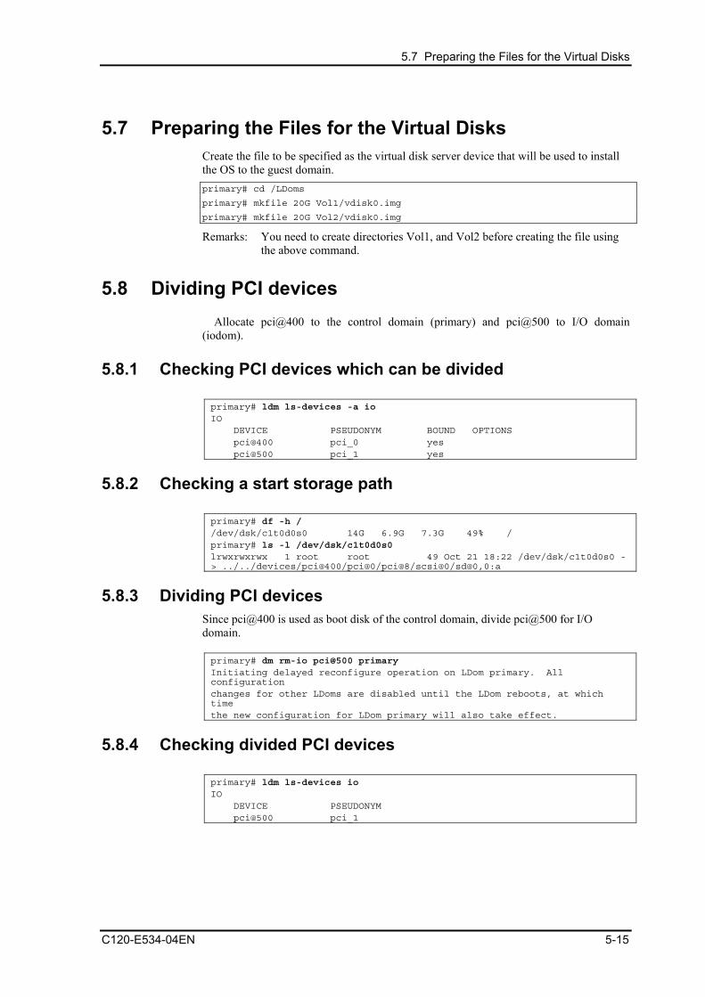
5.7 Preparing the Files for the Virtual Disks
5.7 Preparing the Files for the Virtual Disks Create the file to be specified as the virtual disk server device that will be used to install the OS to the guest domain. primary# cd /LDoms
primary# mkfile 20G Vol1/vdisk0.img
primary# mkfile 20G Vol2/vdisk0.img
Remarks: You need to create directories Vol1, and Vol2 before creating the file using the above command.
5.8 Dividing PCI devices Allocate pci@400 to the control domain (primary) and pci@500 to I/O domain
(iodom).
5.8.1 Checking PCI devices which can be divided primary# ldm ls-devices -a io IO DEVICE PSEUDONYM BOUND OPTIONS pci@400 pci_0 yes pci@500 pci_1 yes
5.8.2 Checking a start storage path primary# df -h / /dev/dsk/c1t0d0s0 14G 6.9G 7.3G 49% / primary# ls -l /dev/dsk/c1t0d0s0 lrwxrwxrwx 1 root root 49 Oct 21 18:22 /dev/dsk/c1t0d0s0 -> ../../devices/pci@400/pci@0/pci@8/scsi@0/sd@0,0:a
5.8.3 Dividing PCI devices Since pci@400 is used as boot disk of the control domain, divide pci@500 for I/O domain. primary# dm rm-io pci@500 primary Initiating delayed reconfigure operation on LDom primary. All configuration changes for other LDoms are disabled until the LDom reboots, at which time the new configuration for LDom primary will also take effect.
5.8.4 Checking divided PCI devices primary# ldm ls-devices io IO DEVICE PSEUDONYM pci@500 pci_1
C120-E534-04EN 5-15
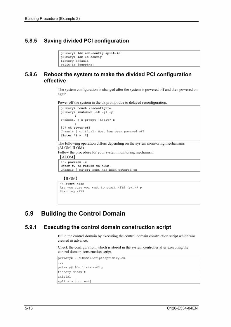
Building Procedure (Example 2)
5.8.5 Saving divided PCI configuration primary# ldm add-config split-io primary# ldm ls-config factory-default split-io [current]
5.8.6 Reboot the system to make the divided PCI configuration effective
The system configuration is changed after the system is powered off and then powered on again.
Power off the system in the ok prompt due to delayed reconfiguration. primary# touch /reconfigure primary# shutdown -i0 -g0 -y : r)eboot, o)k prompt, h)alt? o : {0} ok power-off Chassis | critical: Host has been powered off [Enter "# + ."]
The following operation differs depending on the system monitoring mechanisms (ALOM, ILOM). Follow the procedure for your system monitoring mechanism. 【ALOM】 sc> poweron -c Enter #. to return to ALOM. Chassis | major: Host has been powered on
【ILOM】
-> start /SYS Are you sure you want to start /SYS (y/n)? y Starting /SYS
5.9 Building the Control Domain
5.9.1 Executing the control domain construction script Build the control domain by executing the control domain construction script which was created in advance.
Check the configuration, which is stored in the system controller after executing the control domain construction script. primary# . /LDoms/Scripts/primary.sh
...
primary# ldm list-config
factory-default
initial
split-io [current]
5-16 C120-E534-04EN
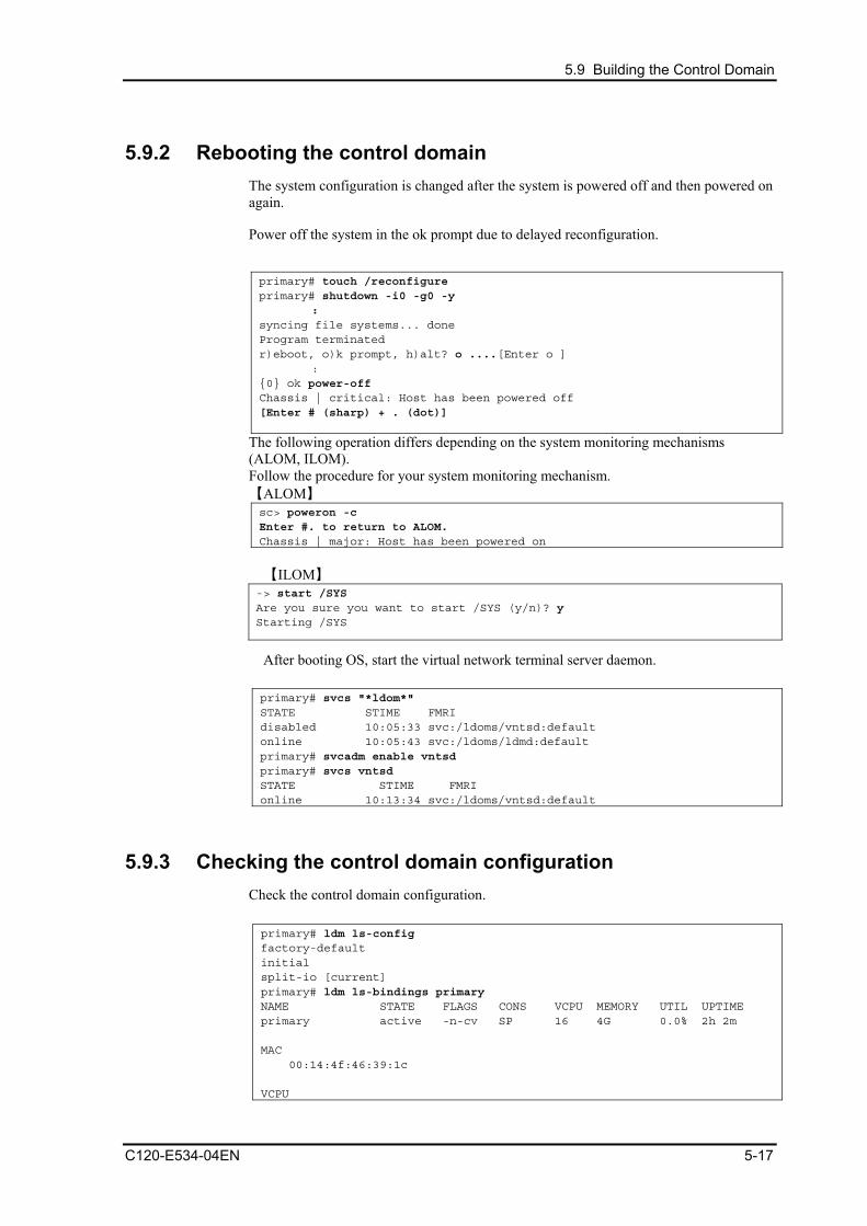
5.9 Building the Control Domain
5.9.2 Rebooting the control domain The system configuration is changed after the system is powered off and then powered on again.
Power off the system in the ok prompt due to delayed reconfiguration.
primary# touch /reconfigure primary# shutdown -i0 -g0 -y : syncing file systems... done Program terminated r)eboot, o)k prompt, h)alt? o ....[Enter o ] : {0} ok power-off Chassis | critical: Host has been powered off [Enter # (sharp) + . (dot)]
The following operation differs depending on the system monitoring mechanisms (ALOM, ILOM). Follow the procedure for your system monitoring mechanism. 【ALOM】 sc> poweron -c Enter #. to return to ALOM. Chassis | major: Host has been powered on
【ILOM】
-> start /SYS Are you sure you want to start /SYS (y/n)? y Starting /SYS
After booting OS, start the virtual network terminal server daemon. primary# svcs "*ldom*" STATE STIME FMRI disabled 10:05:33 svc:/ldoms/vntsd:default online 10:05:43 svc:/ldoms/ldmd:default primary# svcadm enable vntsd primary# svcs vntsd STATE STIME FMRI online 10:13:34 svc:/ldoms/vntsd:default
5.9.3 Checking the control domain configuration Check the control domain configuration. primary# ldm ls-config factory-default initial split-io [current] primary# ldm ls-bindings primary NAME STATE FLAGS CONS VCPU MEMORY UTIL UPTIME primary active -n-cv SP 16 4G 0.0% 2h 2m MAC 00:14:4f:46:39:1c VCPU
C120-E534-04EN 5-17

Building Procedure (Example 2)
VID PID UTIL STRAND 0 0 0.6% 100% 1 1 0.0% 100% 2 2 0.0% 100% 3 3 0.0% 100% 4 4 0.0% 100% 5 5 0.0% 100% 6 6 0.0% 100% 7 7 0.0% 100% 8 8 0.1% 100% 9 9 0.0% 100% 10 10 0.0% 100% 11 11 0.0% 100% 12 12 0.0% 100% 13 13 0.0% 100% 14 14 0.0% 100% 15 15 0.0% 100% 24 24 0.5% 100% 25 25 0.0% 100% 26 26 0.0% 100% 27 27 0.0% 100% 28 28 0.2% 100% 29 29 0.0% 100% 30 30 0.0% 100% 31 31 0.0% 100% 32 32 100% 100% 33 33 100% 100% 34 34 100% 100% 35 35 100% 100% 36 36 100% 100% 37 37 100% 100% 38 38 100% 100% 39 39 100% 100% MEMORY RA PA SIZE 0xe000000 0xe000000 4G VARIABLES boot-device=disk net keyboard-layout=US-English IO DEVICE PSEUDONYM OPTIONS pci@400 pci_0 VCC NAME PORT-RANGE primary-vcc 5000-5100 VDS NAME VOLUME OPTIONS DEVICE primary-vds0 VCONS NAME SERVICE PORT SP primary#
5-18 C120-E534-04EN
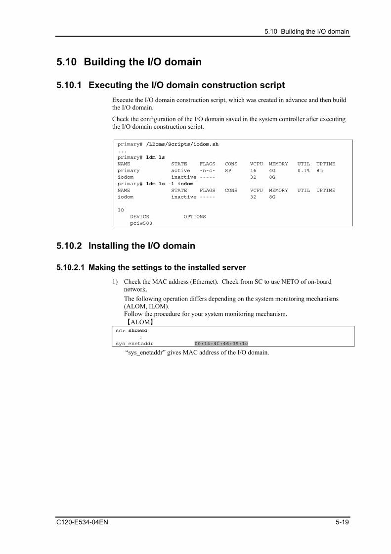
5.10 Building the I/O domain
5.10 Building the I/O domain
5.10.1 Executing the I/O domain construction script Execute the I/O domain construction script, which was created in advance and then build the I/O domain.
Check the configuration of the I/O domain saved in the system controller after executing the I/O domain construction script. primary# /LDoms/Scripts/iodom.sh ... primary# ldm ls NAME STATE FLAGS CONS VCPU MEMORY UTIL UPTIME primary active -n-c- SP 16 4G 0.1% 8m iodom inactive ----- 32 8G primary# ldm ls -l iodom NAME STATE FLAGS CONS VCPU MEMORY UTIL UPTIME iodom inactive ----- 32 8G IO DEVICE OPTIONS pci@500
5.10.2 Installing the I/O domain
5.10.2.1 Making the settings to the installed server 1) Check the MAC address (Ethernet). Check from SC to use NETO of on-board
network. The following operation differs depending on the system monitoring mechanisms (ALOM, ILOM). Follow the procedure for your system monitoring mechanism. 【ALOM】
sc> showsc :
sys_enetaddr 00:14:4f:46:39:1c
“sys_enetaddr” gives MAC address of the I/O domain.
C120-E534-04EN 5-19
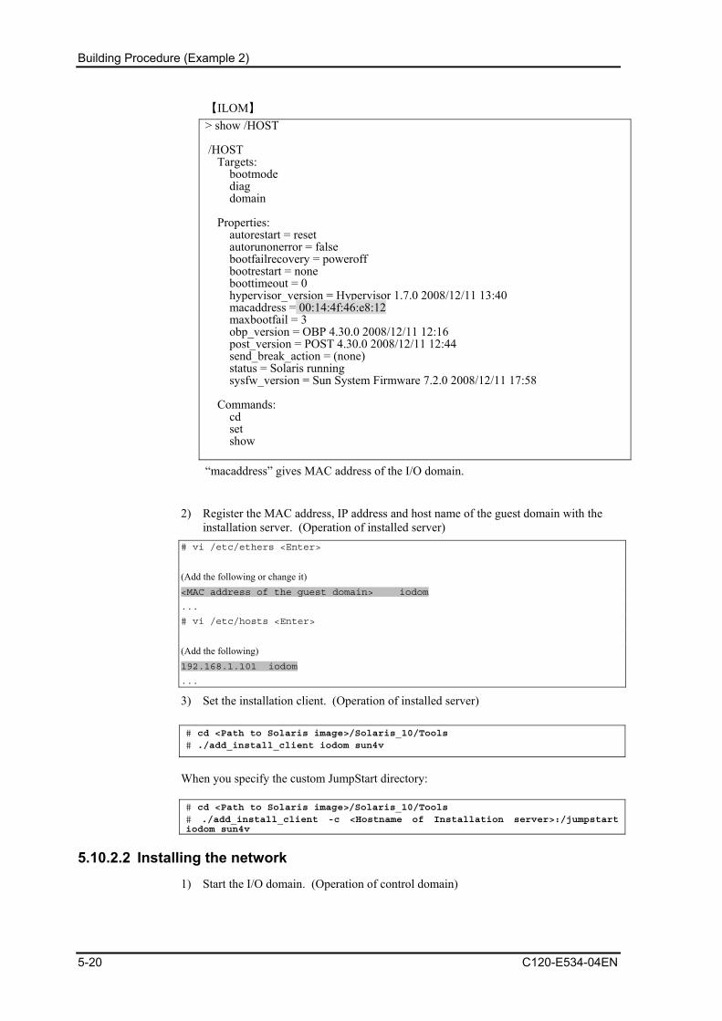
Building Procedure (Example 2)
【ILOM】 > show /HOST /HOST Targets: bootmode diag domain Properties: autorestart = reset autorunonerror = false bootfailrecovery = poweroff bootrestart = none boottimeout = 0 hypervisor_version = Hypervisor 1.7.0 2008/12/11 13:40 macaddress = 00:14:4f:46:e8:12 maxbootfail = 3 obp_version = OBP 4.30.0 2008/12/11 12:16 post_version = POST 4.30.0 2008/12/11 12:44 send_break_action = (none) status = Solaris running sysfw_version = Sun System Firmware 7.2.0 2008/12/11 17:58 Commands: cd set show
“macaddress” gives MAC address of the I/O domain.
2) Register the MAC address, IP address and host name of the guest domain with the installation server. (Operation of installed server)
# vi /etc/ethers <Enter>
(Add the following or change it) <MAC address of the guest domain> iodom
...
# vi /etc/hosts <Enter>
(Add the following) 192.168.1.101 iodom
...
3) Set the installation client. (Operation of installed server) # cd <Path to Solaris image>/Solaris_10/Tools # ./add_install_client iodom sun4v
When you specify the custom JumpStart directory: # cd <Path to Solaris image>/Solaris_10/Tools # ./add_install_client -c <Hostname of Installation server>:/jumpstart iodom sun4v
5.10.2.2 Installing the network 1) Start the I/O domain. (Operation of control domain)
5-20 C120-E534-04EN
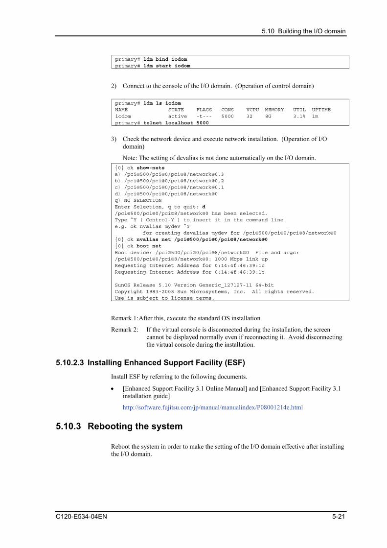
5.10 Building the I/O domain
primary# ldm bind iodom primary# ldm start iodom
2) Connect to the console of the I/O domain. (Operation of control domain) primary# ldm ls iodom NAME STATE FLAGS CONS VCPU MEMORY UTIL UPTIME iodom active -t--- 5000 32 8G 3.1% 1m primary# telnet localhost 5000
3) Check the network device and execute network installation. (Operation of I/O
domain)
Note: The setting of devalias is not done automatically on the I/O domain. {0} ok show-nets a) /pci@500/pci@0/pci@8/network@0,3 b) /pci@500/pci@0/pci@8/network@0,2 c) /pci@500/pci@0/pci@8/network@0,1 d) /pci@500/pci@0/pci@8/network@0 q) NO SELECTION Enter Selection, q to quit: d /pci@500/pci@0/pci@8/network@0 has been selected. Type ^Y ( Control-Y ) to insert it in the command line. e.g. ok nvalias mydev ^Y for creating devalias mydev for /pci@500/pci@0/pci@8/network@0 {0} ok nvalias net /pci@500/pci@0/pci@8/network@0 {0} ok boot net Boot device: /pci@500/pci@0/pci@8/network@0 File and args: /pci@500/pci@0/pci@8/network@0: 1000 Mbps link up Requesting Internet Address for 0:14:4f:46:39:1c Requesting Internet Address for 0:14:4f:46:39:1c SunOS Release 5.10 Version Generic_127127-11 64-bit Copyright 1983-2008 Sun Microsystems, Inc. All rights reserved. Use is subject to license terms.
Remark 1: After this, execute the standard OS installation.
Remark 2: If the virtual console is disconnected during the installation, the screen cannot be displayed normally even if reconnecting it. Avoid disconnecting the virtual console during the installation.
5.10.2.3 Installing Enhanced Support Facility (ESF) Install ESF by referring to the following documents.
• [Enhanced Support Facility 3.1 Online Manual] and [Enhanced Support Facility 3.1 installation guide]
http://software.fujitsu.com/jp/manual/manualindex/P08001214e.html
5.10.3 Rebooting the system Reboot the system in order to make the setting of the I/O domain effective after installing the I/O domain.
C120-E534-04EN 5-21
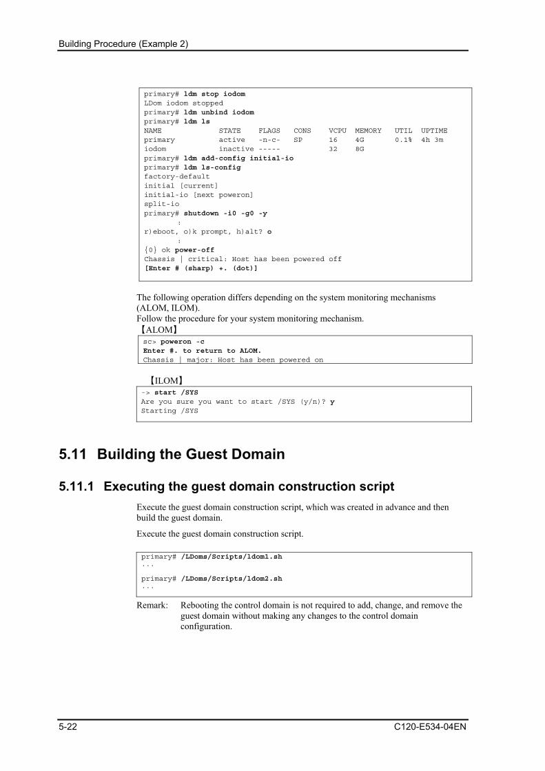
Building Procedure (Example 2)
primary# ldm stop iodom LDom iodom stopped primary# ldm unbind iodom primary# ldm ls NAME STATE FLAGS CONS VCPU MEMORY UTIL UPTIME primary active -n-c- SP 16 4G 0.1% 4h 3m iodom inactive ----- 32 8G primary# ldm add-config initial-io primary# ldm ls-config factory-default initial [current] initial-io [next poweron] split-io primary# shutdown -i0 -g0 -y : r)eboot, o)k prompt, h)alt? o : {0} ok power-off Chassis | critical: Host has been powered off [Enter # (sharp) +. (dot)]
The following operation differs depending on the system monitoring mechanisms (ALOM, ILOM). Follow the procedure for your system monitoring mechanism. 【ALOM】 sc> poweron -c Enter #. to return to ALOM. Chassis | major: Host has been powered on
【ILOM】
-> start /SYS Are you sure you want to start /SYS (y/n)? y Starting /SYS
5.11 Building the Guest Domain
5.11.1 Executing the guest domain construction script Execute the guest domain construction script, which was created in advance and then build the guest domain.
Execute the guest domain construction script. primary# /LDoms/Scripts/ldom1.sh ... primary# /LDoms/Scripts/ldom2.sh ...
Remark: Rebooting the control domain is not required to add, change, and remove the guest domain without making any changes to the control domain configuration.
5-22 C120-E534-04EN

5.11 Building the Guest Domain
5.11.2 Checking the guest domain console Check whether you can access the guest domain console by using the virtual console.
After the connection, you can check the virtual environment by using the OBP command.
C120-E534-04EN 5-23

Building Procedure (Example 2)
primary# svcadm enable svc:/ldoms/vntsd:default
primary# telnet localhost 5001
Trying 127.0.0.1...
Connected to localhost.
Escape character is '^]'.
Connecting to console "ldom1" in group "ldom1" ....
Press ~? for control options ..
{0} ok banner
SPARC Enterprise T5120, No Keyboard
Copyright 2007 Sun Microsystems, Inc. All rights reserved.
OpenBoot 4.27.10, 1920 MB memory available, Serial #66815149.
Ethernet address 0:14:4f:fb:84:ad, Host ID: 83fb84ad.
{0} ok devalias
vdisk0 /virtual-devices@100/channel-devices@200/disk@0
vnet1 /virtual-devices@100/channel-devices@200/network@1
vnet0 /virtual-devices@100/channel-devices@200/network@0
net /virtual-devices@100/channel-devices@200/network@0
disk /virtual-devices@100/channel-devices@200/disk@0
virtual-console /virtual-devices/console@1
name aliases
{0} ok show-devs
/cpu@f
/cpu@e
/cpu@d
/cpu@c
/cpu@b
/cpu@a
/cpu@9
/cpu@8
/cpu@7
/cpu@6
/cpu@5
/cpu@4
/cpu@3
/cpu@2
/cpu@1
/cpu@0
/virtual-devices@100
/virtual-memory
/memory@m0,8000000
/aliases
/options
/openprom
More [<space>,<cr>,q,n,p,c] ?
Remarks:
- When returning to the control domain, enter [~(tilde)] and [. (dot)] sequentially. In the case of connecting to the control domain with ssh, the connection to the control
5-24 C120-E534-04EN

5.11 Building the Guest Domain
domain is disconnected using this operation. If you do not want to disconnect from the control domain, enter the [.] after entering the [~ (tilde)] + [~ (tilde)] + [. (dot)] and a number of [~] equivalent to the layer that uses ssh + 1.
- When sending the break signal, enter [~(tilde)] and [#(sharp)] sequentially.
- The MAC address that is indicated by the above banner command, has no relationship to the virtual network device (vnet0, vnet1). Check the MAC address of the virtual network device by outputting the ldm list-bindings command.
C120-E534-04EN 5-25
Building Procedure (Example 2)
5.12 Retaining the LDoms Configuration Information The hypervisor reads the LDoms configuration stored in EEPROM at the time of power activation. The LDoms configuration may be lost as a result of a failure of hardware, which includes EEPROM, such as a motherboard.
The LDoms Manager starts the guest domain by referring to the LDoms configuration which has been stored on the disk (/var/opt/SUNWldm/). If this disk cannot be accessed, the guest domain will not start the guest domain.
The following corrective actions are recommended for these conditions.
• Save of the construction script
Save the construction script in a certain location (/LDoms/Scripts/ in this document) so that the latest control domain construction script (primary.sh in this document) or guest domain construction script (ldom?.sh in this document) can be executed as required, and so that the LDoms environment can be rebuilt.
• Collection/Save of the guest domain configuration information
The outputs of ldm list-constraints -x [domain-name] when used for the input of ldm add-domain -i [file-name], can rebuild the collected guest domain. Collect the configuration information of the guest domain whenever the configuration is changed and save it in a certain location (/LDoms/Domains/ in this document).
• Save of the information to external media
Copy the information in the CD-R, DVD-R, tapes or file servers to be prepared in case they are lost from the disk.
5-26 C120-E534-04EN

5.13 Installing the Guest domain
5.13 Installing the Guest domain The OS installation of the guest domain is executed using the network installation method as well as the standard OS. Fujitsu recommends preparing another chassis for the installation server. The cancellation of the SST security configuration and the setting for virtual network communication between the control domain and guest domain are required although it is possible to use the control domain as the installation server.
5.13.1 Making the settings to the installed server 1) Check the MAC address (Ethernet) of the guest domain (ldom1 in the following
example). (Operation of control domain) primary$ ldm ls -l ldom1 <Enter>
: NETWORK
NAME SERVICE DEVICE MAC
vnet0 primary-vsw0@primary network@0 <MAC address of the guest domain>
Remarks: DO NOT USE the result displayed by the banner command of the guest domain OBP.
2) Register the MAC address, IP address and host name of the guest domain with the installation server. (Operation of installed server)
# vi /etc/ethers <Enter>
(Add the following) <MAC address of the guest domain> ldom1
...
# vi /etc/hosts <Enter>
(Add the following) 192.168.1.101 ldom1
...
3) Set the installation client. (Operation of installed server)
Remarks: Create the Solaris install image of the installation server in advance. # cd <path to the Solaris image>/Solaris_10/Tools <Enter>
# ./add_install_client -e <MAC address of the guest domain> ldom1 sun4v <Enter>
4) Confirm the setting. (Operation of installed server) # cat /etc/bootparams <Enter>
ldom1 root=192.168.1.100:/export/image/solaris10_8_07/Solaris_10/Tools/
Bootinstall=192.168.1.100:/export/image/solaris10_8_07/ boottype=:in rootopts=:rsize=8192
C120-E534-04EN 5-27

Building Procedure (Example 2)
5) Share the install image. (Operation of installed server.)
Remarks: It is not necessary to execute the command when sharing has already been done.
# share -o ro,anon=0 /export/image <Enter>
5.13.2 Installing the network 1) Connect to the console of the guest domain. (Operation of control domain)
primary$ telnet localhost 5001 <Enter>
2) Check the virtual network device. (Operation of guest domain) {0} ok devalias <Enter>
vdisk0 /virtual-devices@100/channel-devices@200/disk@0
vnet1 /virtual-devices@100/channel-devices@200/network@1
vnet0 /virtual-devices@100/channel-devices@200/network@0
net /virtual-devices@100/channel-devices@200/network@0
disk /virtual-devices@100/channel-devices@200/disk@0
virtual-console /virtual-devices/console@1
name aliases
{0} ok
Remarks: The devices indicated with other net or disk names are not available in a guest domain other than the I/O domain.
3) Execute network installation. (Operation of guest domain) {0} ok boot vnet0 <Enter>
Boot device: /virtual-devices@100/channel-devices@200/network@0 File and args:
:
SunOS Release 5.10 Version Generic_120011-14 64-bit
Copyright 1983-2007 Sun Microsystems, Inc. All rights reserved.Use is subject to license terms.
:
whoami: no domain name
Configuring devices.
Using RPC Bootparams for network configuration information.
Attempting to configure interface vnet0...
Configured interface vnet0
Beginning system identification...
Searching for configuration file(s)...
Search complete.
Discovering additional network configuration...
Remarks:
- After this, execute the standard OS installation.
- The virtual disk names (c0d0s0, etc) are displayed as the disk name in the guest domain.
- The virtual network device names (vnet0,etc) are displayed as the network device name in the guest domain.
- If the virtual console is disconnected during the installation, the screen cannot be displayed normally even if reconnecting. Avoid disconnecting the virtual console during the installation.
5-28 C120-E534-04EN

5.13 Installing the Guest domain
C120-E534-04EN 5-29
5.13.3 Installing Enhanced Support Facility (ESF) Install ESF by referring to the following documents.
• [Enhanced Support Facility 3.1 Online Manual] and [Enhanced Support Facility 3.1 installation guide]
http://software.fujitsu.com/jp/manual/manualindex/P08001214e.html
5.13.4 Saving the LDoms setting After determining the configuration of your operation, please save the configuration and make a backup of the LDoms setting again. # ldm add-config operation
Regarding the backup of the LDoms configuration, please refer to “Appendix A Procedures of Backing up/Restoring”.

Chapter 6 Installing LDoms Manager
6.1 Upgrading Firmware The firmware must be upgraded when the firmware version is not supported. Also, in order to use the new functions, the firmware may need to be upgraded. You can download the firmware for upgrading from the official Fujitsu site.
6.1.1 Downloading the latest firmware You can download the latest firmware from the following official Fujitsu site:
http://www.fujitsu.com/global/services/computing/server/sparcenterprise/downloads/firmware/
6.1.2 Upgrading the firmware of a system with a configured LDoms environment
When upgrading the firmware of the system with a configured LDoms environment, stop all of the guest domains, release the resource binding, after preserving the logical domain composition referring to "7.7.5 Modification of OBP variables, device-alias etc." ,shut down the power, and then start upgrading the firmware.
# ldm list
NAME STATE FLAGS CONS VCPU MEMORY UTIL UPTIME
primary active -n-cv SP 8 1G 0.6% 52m
ldom1 active -n--- 5001 16 1920M 0.8% 36m
ldom2 active -n--- 5002 16 1G 6.2% 36m
ldom3 active -n--- 5003 24 4G 1.0% 36m
# ldm stop-domain -a
LDom ldom1 stopped
LDom ldom2 stopped
LDom ldom3 stopped
# ldm unbind-domain ldom1
# ldm unbind-domain ldom2
# ldm unbind-domain ldom3
# shutdown -y -g0 -i5
...
C120-E534-04EN 6-1

Installing LDoms Manager
6.1.3 Firmware upgrading procedure 1) Shut down the power to the system to be upgraded.
2) Unzip the downloaded firmware (127580-04.zip in the following example) on the system on which a web browser is available.
# unzip 127580-04.zip
Archive: 127580-04.zip
creating: 127580-04/
inflating: 127580-04/copyright
inflating: 127580-04/sysfw700_README_docs.html
inflating: 127580-04/Install.info
inflating: 127580-04/sysfw700_README_docs.css
inflating: 127580-04/PRDD-Sun_System_Firmware-7_x-SPARC_Enterprise_T5120-T5220.odt
inflating: 127580-04/sysfwdownload
inflating: 127580-04/Entitlement-Sun_System_Firmware.txt
inflating: 127580-04/sysfwdownload.README
inflating: 127580-04/README.127580-04
inflating: 127580-04/Sun_System_Firmware-7_0_9-Sparc_Enterprise_T5120+5220.pkg
inflating: 127580-04/LEGAL_LICENSE.TXT
#
Remarks: In this example, the firmware update file is [Sun_System_Firmware-7_0_9-Sparc_Enterprise_T5120+5220.pkg].
3) Log into the system controller through the WEB browser.
Remarks: The login user needs the administrator authority for the system controller.
6-2 C120-E534-04EN

6.1 Upgrading Firmware
Figure 6.1 [Login] window
4) Select [Maintenance] → [Firmware Upgrade]. The [Firmware Upgrade] page is displayed.
C120-E534-04EN 6-3
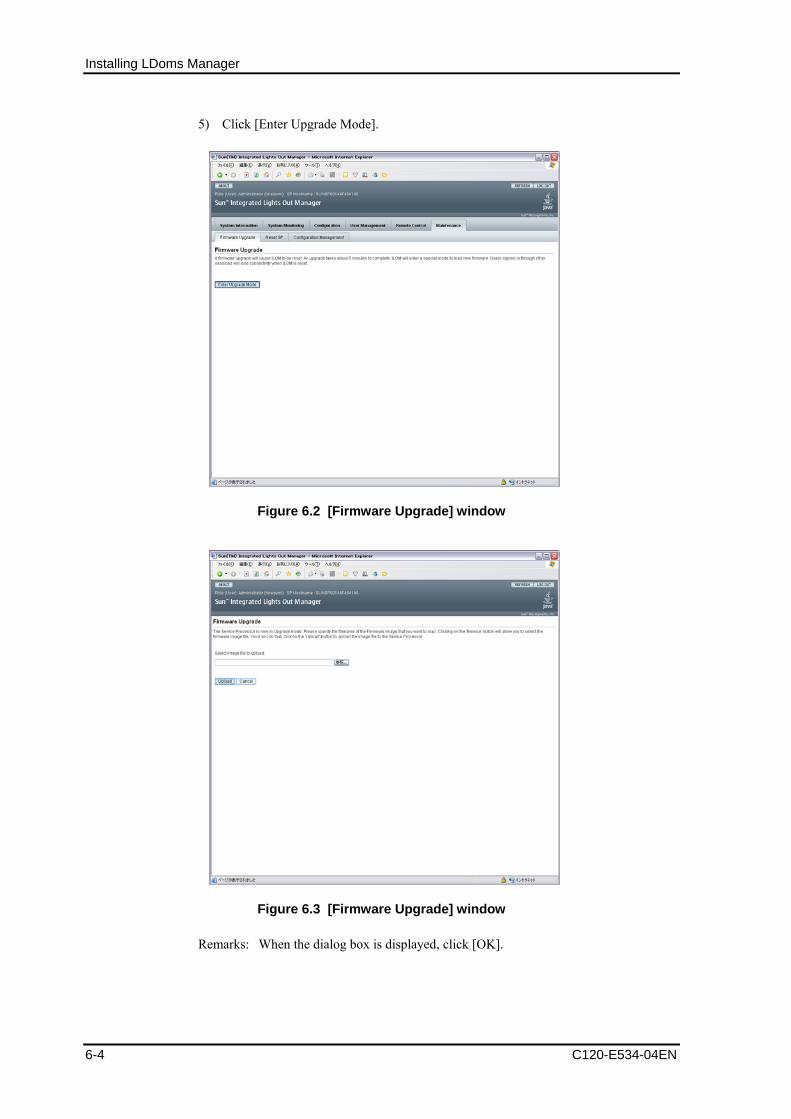
Installing LDoms Manager
5) Click [Enter Upgrade Mode].
Figure 6.2 [Firmware Upgrade] window
Figure 6.3 [Firmware Upgrade] window
Remarks: When the dialog box is displayed, click [OK].
6-4 C120-E534-04EN
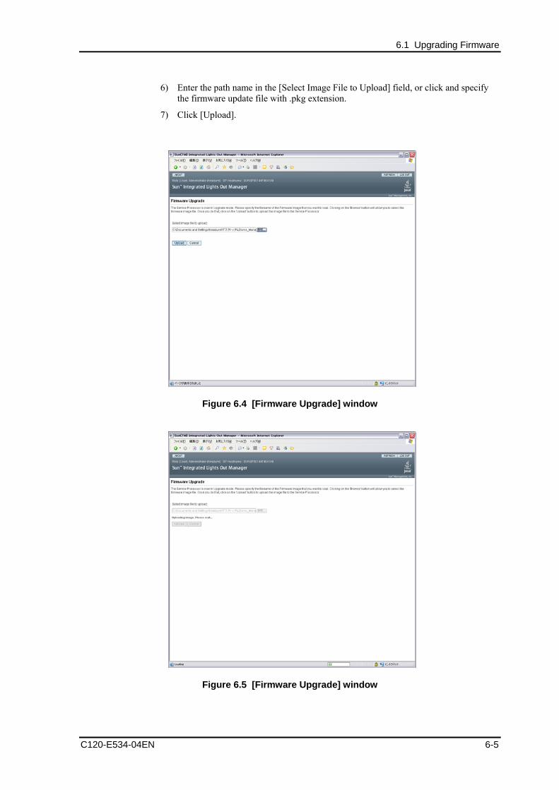
6.1 Upgrading Firmware
6) Enter the path name in the [Select Image File to Upload] field, or click and specify the firmware update file with .pkg extension.
7) Click [Upload].
Figure 6.4 [Firmware Upgrade] window
Figure 6.5 [Firmware Upgrade] window
C120-E534-04EN 6-5

Installing LDoms Manager
8) When the [Verify Firmware Image] page is displayed, click [OK].
9) Select [Preserve Configuration] and then click [Start Upgrade].
Figure 6.6 [Firmware Upgrade] window
Remarks: When the dialog box is displayed, click the [OK].
10) The progress screen is indicated in upgrading the firmware.
When the upgrade is completed, the system controller reboots automatically.
Figure 6.7 [Firmware Upgrade] window
6-6 C120-E534-04EN

6.1 Upgrading Firmware
11) Confirm the version of the firmware.
The following operation differs depending on the system monitoring mechanisms (ALOM, ILOM).
Follow the procedure for your system monitoring mechanism.
【ALOM】
After rebooting the system controller (SC), connect the firmware to confirm the version.
$ ssh T5120-SC
Password:
Waiting for daemons to initialize...
Daemons ready
Sun(TM) Integrated Lights Out Manager
Version 2.0.4.16
Copyright 2007 Sun Microsystems, Inc. All rights reserved.
Use is subject to license terms.
sc> showhost
Sun System Firmware 7.0.9 2007/12/07 17:06
Host flash versions:
Hypervisor 1.5.6 2007/11/30 08:29
OBP 4.27.10 2007/12/07 10:45
POST 4.27.10 2007/12/07 11:10
sc> poweron -c
Enter #. to return to ALOM.
Chassis | major: Host has been powered on
Remarks: In the above case, the firmware version is 7.0.9.
C120-E534-04EN 6-7
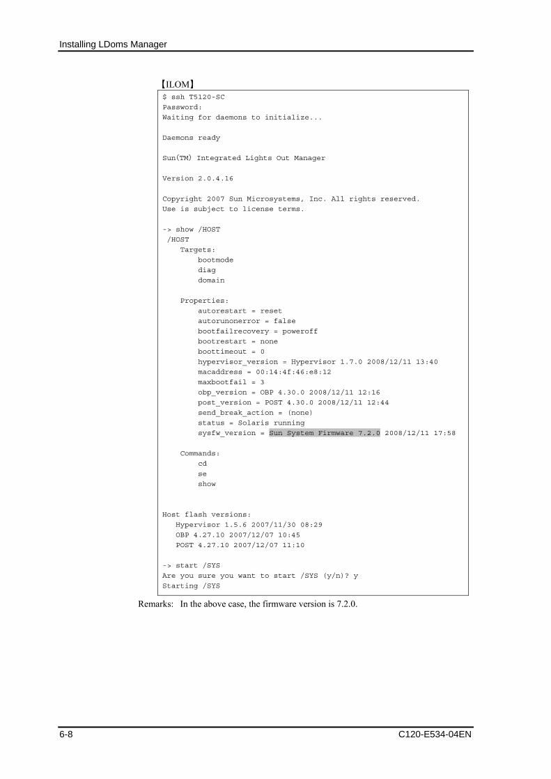
Installing LDoms Manager
【ILOM】 $ ssh T5120-SC
Password:
Waiting for daemons to initialize...
Daemons ready
Sun(TM) Integrated Lights Out Manager
Version 2.0.4.16
Copyright 2007 Sun Microsystems, Inc. All rights reserved.
Use is subject to license terms.
-> show /HOST
/HOST
Targets:
bootmode
diag
domain
Properties:
autorestart = reset
autorunonerror = false
bootfailrecovery = poweroff
bootrestart = none
boottimeout = 0
hypervisor_version = Hypervisor 1.7.0 2008/12/11 13:40
macaddress = 00:14:4f:46:e8:12
maxbootfail = 3
obp_version = OBP 4.30.0 2008/12/11 12:16
post_version = POST 4.30.0 2008/12/11 12:44
send_break_action = (none)
status = Solaris running
sysfw_version = Sun System Firmware 7.2.0 2008/12/11 17:58
Commands:
cd
se
show
Host flash versions:
Hypervisor 1.5.6 2007/11/30 08:29
OBP 4.27.10 2007/12/07 10:45
POST 4.27.10 2007/12/07 11:10
-> start /SYS
Are you sure you want to start /SYS (y/n)? y
Starting /SYS
Remarks: In the above case, the firmware version is 7.2.0.
6-8 C120-E534-04EN

6.2 Installing the OS for the Control Domain
6.2 Installing the OS for the Control Domain
6.2.1 Installing the Solaris OS For OS of the control domain, specify Core System Support (SUNWCreq) or more as install cluster and install Solaris 10 OS 8/07 or later.
Fujitsu recommends installing Secure Shell (SUNWCssh) additionally when applying the Core System Support. The procedure for installing to the control domain is the same as that for a system without LDoms.
6.2.2 Applying required patches Apply the required patches for the installed Solaris OS and the recommended security patches.
You can download the patches from the following site:
• Recommended & Security Patches
http://www.fujitsu.com/global/support/software/security/products-s/patch-info/
6.2.3 Installing Enhanced Support Facility (ESF) Refer to the following document for information on installing ESF.
• [Enhanced Support Facility 3.1 Online Manual] and [Enhanced Support Facility 3.1 installation guide]
http://software.fujitsu.com/jp/manual/manualindex/P08001214e.html
6.2.4 Sun Explorer Data Collector Use the latest version of Sun Explorer Data Collector 5.10 or later.
The following describes how to check the version of Sun Explorer Data Collector. # /opt/SUNWexplo/bin/explorer –V Explorer version: 5.13 : : #
Note: Install Sun Explorer Data Collector into both control and guest domain.
C120-E534-04EN 6-9
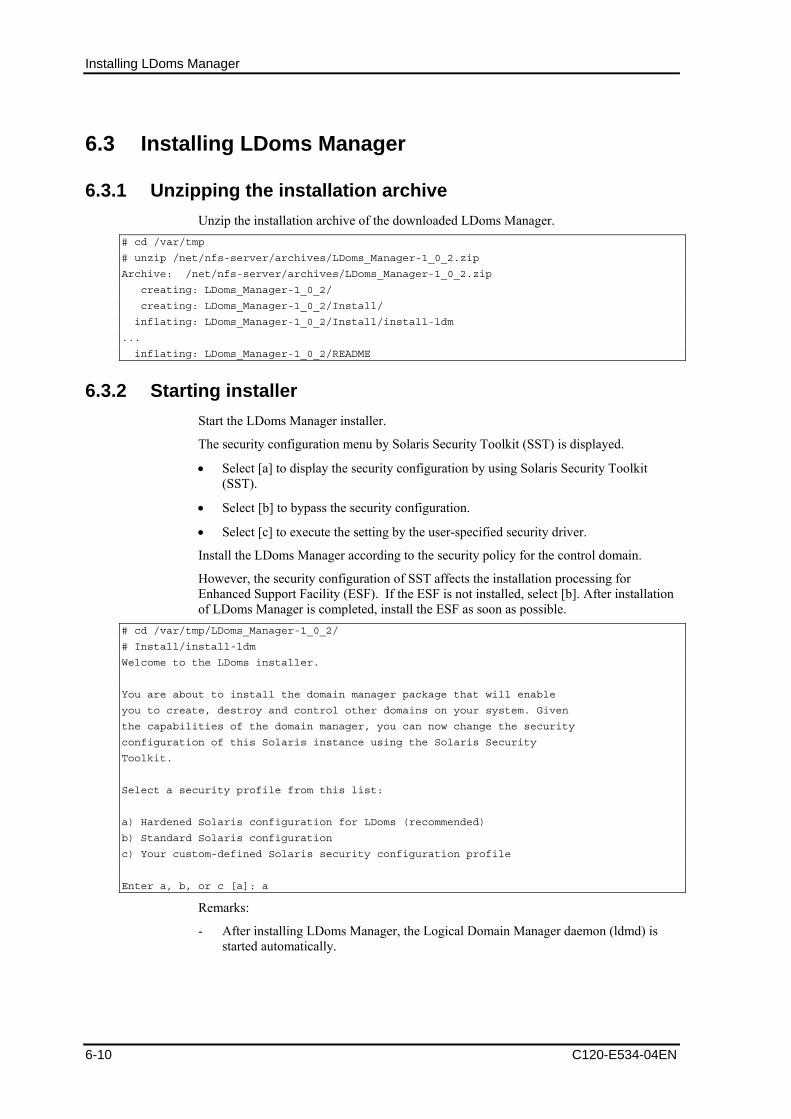
Installing LDoms Manager
6.3 Installing LDoms Manager
6.3.1 Unzipping the installation archive Unzip the installation archive of the downloaded LDoms Manager.
# cd /var/tmp
# unzip /net/nfs-server/archives/LDoms_Manager-1_0_2.zip
Archive: /net/nfs-server/archives/LDoms_Manager-1_0_2.zip
creating: LDoms_Manager-1_0_2/
creating: LDoms_Manager-1_0_2/Install/
inflating: LDoms_Manager-1_0_2/Install/install-ldm
...
inflating: LDoms_Manager-1_0_2/README
6.3.2 Starting installer Start the LDoms Manager installer.
The security configuration menu by Solaris Security Toolkit (SST) is displayed.
• Select [a] to display the security configuration by using Solaris Security Toolkit (SST).
• Select [b] to bypass the security configuration.
• Select [c] to execute the setting by the user-specified security driver.
Install the LDoms Manager according to the security policy for the control domain.
However, the security configuration of SST affects the installation processing for Enhanced Support Facility (ESF). If the ESF is not installed, select [b]. After installation of LDoms Manager is completed, install the ESF as soon as possible.
# cd /var/tmp/LDoms_Manager-1_0_2/
# Install/install-ldm
Welcome to the LDoms installer.
You are about to install the domain manager package that will enable
you to create, destroy and control other domains on your system. Given
the capabilities of the domain manager, you can now change the security
configuration of this Solaris instance using the Solaris Security
Toolkit.
Select a security profile from this list:
a) Hardened Solaris configuration for LDoms (recommended)
b) Standard Solaris configuration
c) Your custom-defined Solaris security configuration profile
Enter a, b, or c [a]: a
Remarks:
- After installing LDoms Manager, the Logical Domain Manager daemon (ldmd) is started automatically.
6-10 C120-E534-04EN
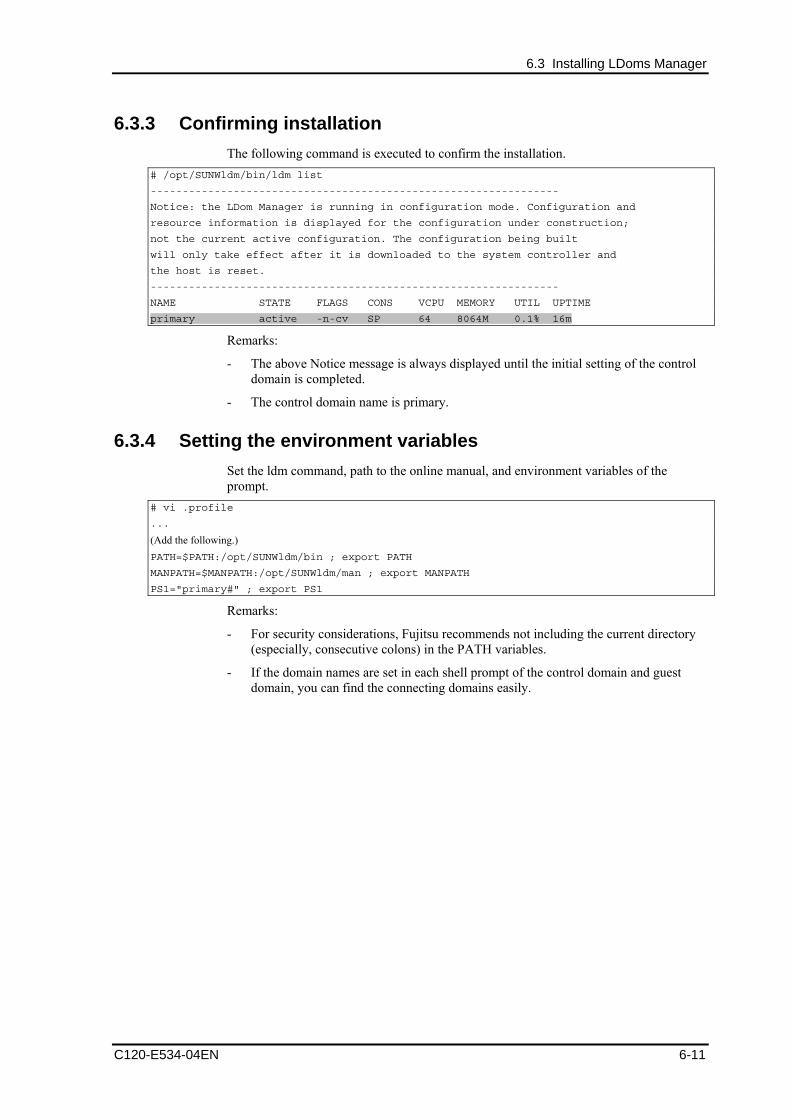
6.3 Installing LDoms Manager
6.3.3 Confirming installation The following command is executed to confirm the installation.
# /opt/SUNWldm/bin/ldm list
----------------------------------------------------------------
Notice: the LDom Manager is running in configuration mode. Configuration and
resource information is displayed for the configuration under construction;
not the current active configuration. The configuration being built
will only take effect after it is downloaded to the system controller and
the host is reset.
----------------------------------------------------------------
NAME STATE FLAGS CONS VCPU MEMORY UTIL UPTIME
primary active -n-cv SP 64 8064M 0.1% 16m
Remarks:
- The above Notice message is always displayed until the initial setting of the control domain is completed.
- The control domain name is primary.
6.3.4 Setting the environment variables Set the ldm command, path to the online manual, and environment variables of the prompt.
# vi .profile
...
(Add the following.) PATH=$PATH:/opt/SUNWldm/bin ; export PATH
MANPATH=$MANPATH:/opt/SUNWldm/man ; export MANPATH
PS1="primary#" ; export PS1
Remarks:
- For security considerations, Fujitsu recommends not including the current directory (especially, consecutive colons) in the PATH variables.
- If the domain names are set in each shell prompt of the control domain and guest domain, you can find the connecting domains easily.
C120-E534-04EN 6-11
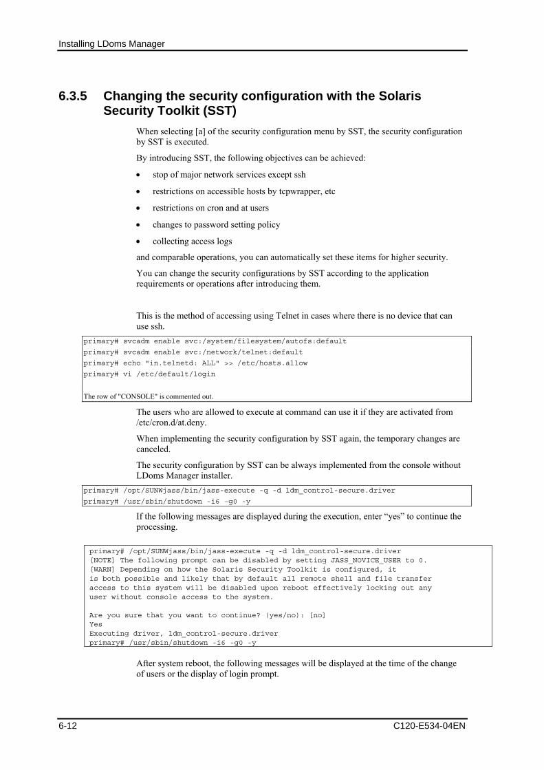
Installing LDoms Manager
6.3.5 Changing the security configuration with the Solaris Security Toolkit (SST)
When selecting [a] of the security configuration menu by SST, the security configuration by SST is executed.
By introducing SST, the following objectives can be achieved:
• stop of major network services except ssh
• restrictions on accessible hosts by tcpwrapper, etc
• restrictions on cron and at users
• changes to password setting policy
• collecting access logs
and comparable operations, you can automatically set these items for higher security.
You can change the security configurations by SST according to the application requirements or operations after introducing them.
This is the method of accessing using Telnet in cases where there is no device that can use ssh.
primary# svcadm enable svc:/system/filesystem/autofs:default
primary# svcadm enable svc:/network/telnet:default
primary# echo "in.telnetd: ALL" >> /etc/hosts.allow
primary# vi /etc/default/login
The row of "CONSOLE" is commented out.
The users who are allowed to execute at command can use it if they are activated from /etc/cron.d/at.deny.
When implementing the security configuration by SST again, the temporary changes are canceled.
The security configuration by SST can be always implemented from the console without LDoms Manager installer.
primary# /opt/SUNWjass/bin/jass-execute -q -d ldm_control-secure.driver
primary# /usr/sbin/shutdown -i6 -g0 -y
If the following messages are displayed during the execution, enter “yes” to continue the processing.
primary# /opt/SUNWjass/bin/jass-execute -q -d ldm_control-secure.driver [NOTE] The following prompt can be disabled by setting JASS_NOVICE_USER to 0. [WARN] Depending on how the Solaris Security Toolkit is configured, it is both possible and likely that by default all remote shell and file transfer access to this system will be disabled upon reboot effectively locking out any user without console access to the system. Are you sure that you want to continue? (yes/no): [no] Yes Executing driver, ldm_control-secure.driver primary# /usr/sbin/shutdown -i6 -g0 -y
After system reboot, the following messages will be displayed at the time of the change of users or the display of login prompt.
6-12 C120-E534-04EN

6.3 Installing LDoms Manager
C120-E534-04EN 6-13
This system is for the use of authorized users only. Individuals using this computer system without authority, or in excess of their authority, are subject to having all of their activities on this system monitored and recorded by system personnel. In the course of monitoring individuals improperly using this system, or in the course of system maintenance, the activities of authorized users may also be monitored. Anyone using this system expressly consents to such monitoring and is advised that if such monitoring reveals possible evidence of criminal activity, system personnel may provide the evidence of such monitoring to law enforcement officials.
Implement the following from the console when you want to cancel the security configuration by SST.
primary# /opt/SUNWjass/bin/jass-execute -u
primary# /usr/sbin/shutdown -i6 -g0 -y
Refer to the following site for details of Solaris Security Toolkit 4.2.
• [Solaris Security Toolkit 4.2 Documentation]
http://docs.sun.com/app/docs/coll/sstoolkit4.2
6.3.6 Checking/resetting the hardware monitoring function Because of the security setting by SST, the setting for the hardware monitoring may be canceled by ESF machine control. After setting the security by using SST, check the setting for hardware monitoring by using the following procedure, and modify the setting when the setting is canceled.
1) Check/Editing of syslog.conf
Check whether the following is written in the /etc/syslog.conf file. If not, add it. *.err;kern.debug;daemon.notice<tab>/var/opt/FJSVmadm/evh/evh_pipe
Remarks: <tab> means pressing the tab key and creating a space before and after the command.
2) Reboot the syslog service to enable the syslog.conf setting. primary# svcadm restart svc:/system/system-log:default

Chapter 7 Operating LDoms
7.1 Confirming the State of/Starting/Stopping the Guest Domain
7.1.1 Confirming the state of the domain 1) Confirm the states of all domains.
primary$ ldm list <Enter>
NAME STATE FLAGS CONS VCPU MEMORY UTIL UPTIME
primary active -n-cv- SP 8 1G 0.6% 52m
ldom1 active -n---- 5001 16 1920M 0.0% 36m
ldom2 bound -t---- 5002 16 1G 6.2% 4m
ldom3 inactive -n---- 5003 24 4G 100% 52m
� STATE:
active: active state
bound: resource bounding state
inactive: resource non-bounding information
� FLAGS:
-: place holder
c: control domain
d: delayed reconstruction state
e: error
n: normal (OS-active) state
s: Column 1 - starting or stopping
Column 6 - source domain
t: Column 2 - transition
Column 6 - target domain
v: virtual I/O service domain
� CONS:
SP: System Processor (System controller)
Values: the port number connected to the domain
� VCPU: number of virtual CPUs
� MEMORY: memory amount
� UTIL: CPU utilization
� UPTIME: uptime
C120-E534-04EN 7-1

Operating LDoms
2) Specify the domain you would like to confirm as follows when checking every domain.
primary$ ldm list ldom1 <Enter>
Remarks: ldm list <domain name>
3) Add and specify -l when checking the detail information.
The following is an example of the output from LDoms Manager 1.0.3. primary$ ldm list -l <Enter>
NAME STATE FLAGS CONS VCPU MEMORY UTIL UPTIME
primary active -n-cv SP 8 1G 0.6% 52m
SOFTSTATE
Solaris running
VCPU
VID PID UTIL STRAND
0 0 1.2% 100%
1 1 0.1% 100%
2 2 0.0% 100%
3 3 0.0% 100%
4 20 0.4% 100%
5 21 0.1% 100%
6 22 0.0% 100%
7 23 0.0% 100%
MEMORY
RA PA SIZE
0x8000000 0x8000000 1G
IO
DEVICE PSEUDONYM OPTIONS
pci@0 pci
niu@80 niu
VDS
NAME VOLUME OPTIONS DEVICE
primary-vds0 vol1 /LDoms/Vol1
vol2 /LDoms/Vol2
vol3 /LDoms/Vol3
VSW
NAME MAC NET-DEV DEVICE MODE
primary-vsw0 00:14:4f:f8:97:91 e1000g0 switch@0 prog,promisc
primary-vsw1 00:14:4f:f9:90:05 e1000g1 switch@1 prog,promisc
primary-vsw2 00:14:4f:fa:65:18 e1000g2 switch@2 prog,promisc
primary-vsw3 00:14:4f:f9:ad:3b e1000g3 switch@3 prog,promisc
VCC
NAME PORT-RANGE
primary-vcc0 5000-5100
Allocated virtual CPU information VID: CPU-ID, which the domains recognize: PID: actual CPU-ID
Allocated memory information
Allocated I/O information
Virtual disk service information
Virtual switch service information
Virtual console distributing device service information
7-2 C120-E534-04EN

7.1 Confirming the State of/Starting/Stopping the Guest Domain
VCONS
NAME SERVICE PORT
SP
-------------------------------------------------------------------------
NAME STATE FLAGS CONS VCPU MEMORY UTIL UPTIME
ldom1 active -n--- 5001 16 1920M 0.0% 36m
SOFTSTATE
Solaris running
VCPU
VID PID UTIL STRAND
0 8 0.3% 100%
1 9 0.0% 100%
2 10 0.0% 100%
3 11 0.1% 100%
4 12 0.0% 100%
5 13 0.1% 100%
6 14 0.0% 100%
7 15 0.0% 100%
8 16 0.1% 100%
9 17 0.0% 100%
10 18 0.0% 100%
11 19 0.0% 100%
12 20 0.0% 100%
13 21 0.0% 100%
14 22 0.0% 100%
15 23 0.0% 100%
MEMORY
RA PA SIZE
0x8000000 0x48000000 1920M
VARIABLES
auto-boot?=false
NETWORK
NAME SERVICE DEVICE MAC
vnet0 primary-vsw0 network@0
vnet1 primary-vsw1 network@1
DISK
NAME VOLUME TOUT DEVICE
vdisk0 vol1@primary-vds0 disk@0
VCONS
NAME SERVICE PORT
ldom1 primary-vcc0@primary 5001
Virtual console information
Setting condition of OBP variables
Virtual network device information
Virtual disk information
Virtual console information
C120-E534-04EN 7-3

Operating LDoms
-------------------------------------------------------------------------
NAME STATE FLAGS CONS VCPU MEMORY UTIL UPTIME
ldom2 bound -t--- 5002 16 1G 6.2% 4m
:
-------------------------------------------------------------------------
NAME STATE FLAGS CONS VCPU MEMORY UTIL UPTIME
ldom3 inactive -n-- 5003 24 4G 100% 52m
:
7.1.2 Starting the domain 1) Confirm the domain state.
primary$ ldm list <Enter>
NAME STATE FLAGS CONS VCPU MEMORY UTIL UPTIME
primary active -n-cv SP 8 1G 0.6% 52m
ldom1 inactive ----- 16 1920M
ldom2 inactive ----- 16 1G
ldom3 inactive ----- 24 4G
Remarks: You can get the same result from [# ldm ls].
2) Bind the resource to the domain.
Remarks:
- DO NOT execute this command when STATE is bound.
- You can get the same result from [# ldm bind domain name]. primary$ ldm bind-domain ldom1 <Enter>
3) Start the domain.
Remarks:
- You can get the same result from [# ldm start domain name].
- You can start in batch all of the domains that are bound when the start-up sequence does not need to be considered.
primary$ ldm start-domain ldom1 <Enter>
primary$ ldm start-domain -a <Enter>
4) Check whether the domain becomes the active state. primary$ ldm list <Enter>
NAME STATE FLAGS CONS VCPU MEMORY UTIL UPTIME
primary active -n-cv SP 8 1G 0.6% 52m
ldom1 active -n--- 5001 16 1920M 17% 1s
ldom2 inactive ----- 16 1G
ldom3 inactive ----- 24 4G
7-4 C120-E534-04EN
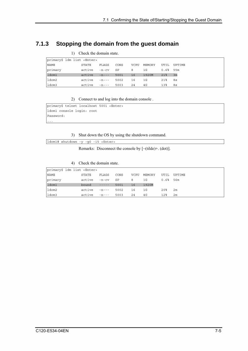
7.1 Confirming the State of/Starting/Stopping the Guest Domain
7.1.3 Stopping the domain from the guest domain 1) Check the domain state.
primary$ ldm list <Enter>
NAME STATE FLAGS CONS VCPU MEMORY UTIL UPTIME
primary active -n-cv SP 8 1G 0.6% 55m
ldom1 active -n--- 5001 16 1920M 21% 3m
ldom2 active -n--- 5002 16 1G 21% 8s
ldom3 active -n--- 5003 24 4G 13% 8s
2) Connect to and log into the domain console . primary$ telnet localhost 5001 <Enter>
ldom1 console login: root
Password:
...
3) Shut down the OS by using the shutdown command. ldom1# shutdown -y -g0 -i5 <Enter>
Remarks: Disconnect the console by [~(tilde)+. (dot)].
4) Check the domain state. primary$ ldm list <Enter>
NAME STATE FLAGS CONS VCPU MEMORY UTIL UPTIME
primary active -n-cv SP 8 1G 0.6% 56m
ldom1 bound ----- 5001 16 1920M
ldom2 active -n--- 5002 16 1G 20% 2m
ldom3 active -n--- 5003 24 4G 12% 2m
C120-E534-04EN 7-5
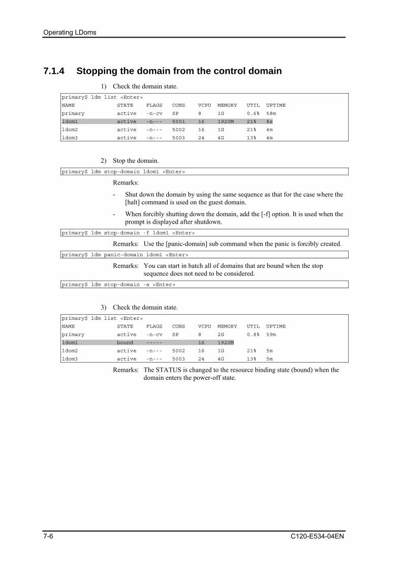
Operating LDoms
7.1.4 Stopping the domain from the control domain 1) Check the domain state.
primary$ ldm list <Enter>
NAME STATE FLAGS CONS VCPU MEMORY UTIL UPTIME
primary active -n-cv SP 8 1G 0.6% 58m
ldom1 active -n--- 5001 16 1920M 21% 8s
ldom2 active -n--- 5002 16 1G 21% 4m
ldom3 active -n--- 5003 24 4G 13% 4m
2) Stop the domain. primary$ ldm stop-domain ldom1 <Enter>
Remarks:
- Shut down the domain by using the same sequence as that for the case where the [halt] command is used on the guest domain.
- When forcibly shutting down the domain, add the [-f] option. It is used when the prompt is displayed after shutdown.
primary$ ldm stop-domain -f ldom1 <Enter>
Remarks: Use the [panic-domain] sub command when the panic is forcibly created. primary$ ldm panic-domain ldom1 <Enter>
Remarks: You can start in batch all of domains that are bound when the stop sequence does not need to be considered.
primary$ ldm stop-domain -a <Enter>
3) Check the domain state. primary$ ldm list <Enter>
NAME STATE FLAGS CONS VCPU MEMORY UTIL UPTIME
primary active -n-cv SP 8 2G 0.8% 59m
ldom1 bound ----- 16 1920M
ldom2 active -n--- 5002 16 1G 21% 5m
ldom3 active -n--- 5003 24 4G 13% 5m
Remarks: The STATUS is changed to the resource binding state (bound) when the domain enters the power-off state.
7-6 C120-E534-04EN

7.1 Confirming the State of/Starting/Stopping the Guest Domain
7.1.5 How to acquire the crash dump of the guest domain This is the process for creating the crash dump for the fault investigation of the guest domain.
1) Log into the guest domain to confirm the crash dump information. ldom1# dumpadm <Enter>
Dump content: kernel page
Dump device: /dev/dsk/c0d0s1 (swap)
Savecore directory:/var/crash/ldom2
Valid savecore: yes
Remarks: Refer to the dumpadm (1M) manual when changing it.
2) Generate a panic from the control domain to the guest domain. primary$ ldm panic-domain <domain name> <Enter>
3) Check the created dump file after rebooting the guest domain. ldom1# ls -l /var/crash/ldom2 <Enter>
-rw-r--r-- 1 root root 2 Jan. 9 11:58 bounds
-rw-r--r-- 1 root root 1232962 Jan. 9 11:58 unix.0
-rw-r--r-- 1 root root 126697472 Jan. 9 11:58 vmcore.0
Remarks: Save the output file by using arbitrary methods.
C120-E534-04EN 7-7

Operating LDoms
7.2 Console of the Guest Domain
7.2.1 Connecting/disconnecting the guest domain to/from the console
1) Check the port numbers of the virtual console. primary$ ldm list ldom1 <Enter>
NAME STATE FLAGS CONS VCPU MEMORY UTIL UPTIME
ldom1 active -n--- 5001 16 1920M 6.2% 23m
2) Connect to the console of the guest domain. primary$ telnet localhost 5001 <Enter>
The following message is displayed, and enter the root user's ID and password. Trying 127.0.0.1...
Connected to localhost.
Escape character is '^]'.
Connecting to console "ldom1" in group "ldom1" ....
Press ~? for control options ..
ldom1 console login: root <Enter>
Password:******** <Enter>
Dec 18 16:40:35 ldom1 login: ROOT LOGIN /dev/console
Last login: Tue Dec 18 09:16:30 from 10.77.134.148
Sun Microsystems Inc. SunOS 5.10 Generic January 2005
ldom1#
3) Disconnection of the guest domain console
Enter [~ (tilde)] + [. (dot)] in succession and disconnect the virtual console session of the guest domain.
ldom1# (Nothing is displayed.) Connection to localhost closed by foreign host.
primary$
Remarks: In this example, the logout process may not be executed but the connection to the guest domain console and virtual console is disconnected. This is similar to a situation where a user leaves a console unattended without logging out. For security management purposes, Fujitsu recommends logging out from the console and then disconnecting it.
7-8 C120-E534-04EN

7.2 Console of the Guest Domain
7.2.2 Grouping the virtual console When one administrator controls several domains, he or she can replace the domain without stopping the telnet session by using the virtual console group.
1) Stop the domain you want to group and then release the resource binding. primary$ ldm list
NAME STATE FLAGS CONS VCPU MEMORY UTIL UPTIME
primary active -n-cv SP 8 1G 0.6% 52m
ldom1 active -n--- 5001 16 1920M 0.0% 36m
ldom2 active -t--- 5002 16 1G 6.2% 4m
ldom3 active -t--- 5003 24 4G 100% 52m
primary$ ldm stop-domain ldom2
primary$ ldm stop-domain ldom3
primary$ ldm unbind-domain ldom2
primary$ ldm unbind-domain ldom3
2) Reconfigure the virtual console of the domain that cancels the resource binding. primary$ ldm set-vcons port=5001 group=ldom1 ldom2
primary$ ldm set-vcons port=5001 group=ldom1 ldom3
primary$ ldm bind ldom2
primary$ ldm bind ldom3
primary$ ldm list
NAME STATE FLAGS CONS VCPU MEMORY UTIL UPTIME
primary active -n-cv SP 8 1G 0.2% 56m
ldom1 active -n--- 5001 16 1920M 0.0% 41m
ldom2 bound ----- 5001 16 1G
ldom3 bound ----- 5001 24 4G
primary$ ldm start ldom2
LDom ldom2 started
primary$ ldm start ldom3
LDom ldom3 started
primary$ ldm list
NAME STATE FLAGS CONS VCPU MEMORY UTIL UPTIME
primary active -n-cv SP 8 1G 0.3% 57m
ldom1 active -n--- 5001 16 1920M 0.0% 41m
ldom2 active -t--- 5001 16 1G 9.1% 3s
ldom3 active -t--- 5001 24 4G 32% 0s
C120-E534-04EN 7-9

Operating LDoms
3) Connect to the grouped virtual console group. primary$ ldm list
NAME STATE FLAGS CONS VCPU MEMORY UTIL UPTIME
primary active -n-cv SP 8 1G 0.3% 57m
ldom1 active -n--- 5001 16 1920M 0.0% 41m
ldom2 active -t--- 5001 16 1G 9.1% 3s
ldom3 active -t--- 5001 24 4G 32% 0s
primary$ telnet localhost 5001 <Enter>
Trying 127.0.0.1...
Connected to localhost.
Escape character is '^]'.
T5120-vnts-ldom1: h, l, c{id}, n{name}, q: l <Enter> ← (The list of connected domains is displayed.) DOMAIN ID DOMAIN NAME DOMAIN STATE
0 ldom1 online
1 ldom3 online
2 ldom2 online
T5120-vnts-ldom1: h, l, c{id}, n{name}, q: c 0 <Enter> ← (Specified by c + domain ID) Connecting to console "ldom1 in group "ldom1" ....
Press ~? for control options ..
ldom1 console login:
4) Replace the console with the other domain console. ldom1 console login: Enter [~ (tilde)] + [. (dot)] in succession. T5120-vnts-ldom1: h, l, c{id}, n{name}, q:c1
Connecting to console "ldom2" in group "ldom1" ....
Press ~? for control options ..
{0} ok
Remarks: In case of connecting to the control domain with ssh, the connection to the control domain is disconnected using the above operation. If you do not want to disconnect from the control domain, enter the [.] after entering the [~ (tilde)] + [~ (tilde)] + [. (dot)], and a number of [~] equivalent to the layer that uses ssh + 1.
5) Disconnection of the grouped virtual console
Specify the [q] after entering [~ (tilde)] + [. (dot)] in succession. {0} ok Enter [~ (tilde)] + [. (dot)] in succession. T5120-vnts-ldom1: h, l, c{id}, n{name}, q:q
Connection to localhost closed by foreign host.
primary$
Remarks: In the case of connecting to the control domain with ssh, the connection to the control domain is disconnected using the above operation. If you do not want to disconnect from the control domain, enter the [.] after entering the [~ (tilde)] + [~ (tilde)] + [. (dot)] and a number of [~] equivalent to the layer that uses ssh + 1.
7-10 C120-E534-04EN
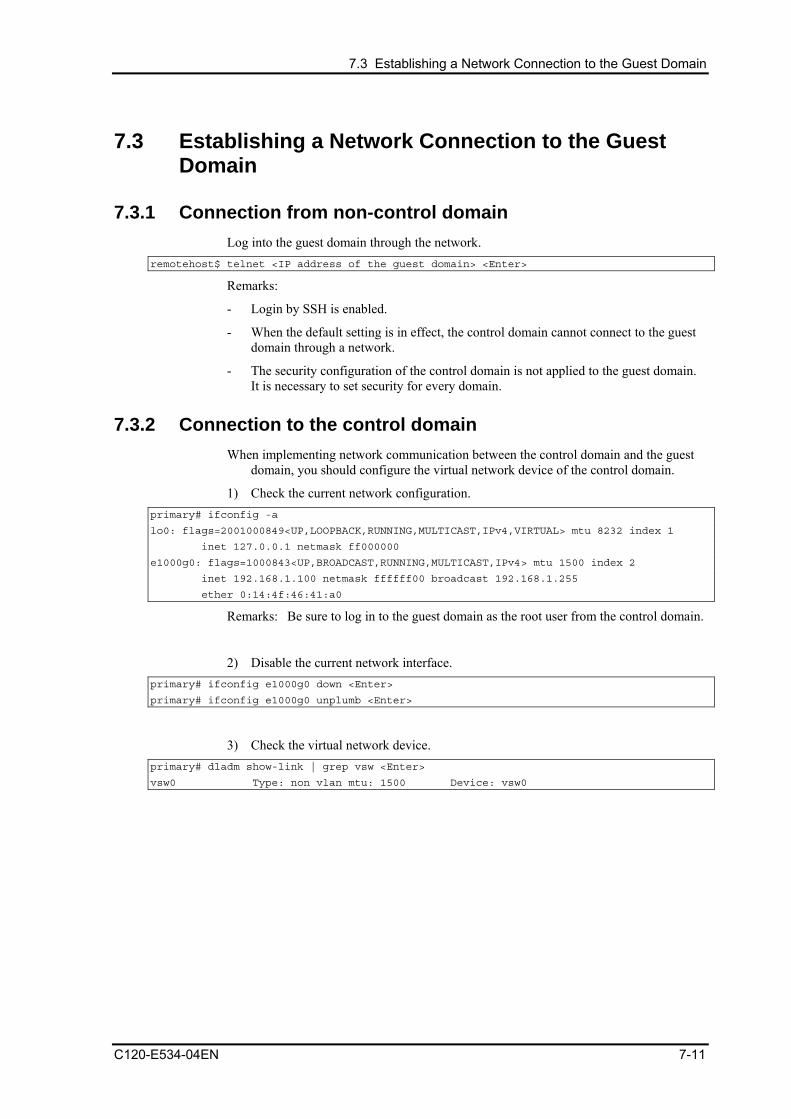
7.3 Establishing a Network Connection to the Guest Domain
7.3 Establishing a Network Connection to the Guest Domain
7.3.1 Connection from non-control domain Log into the guest domain through the network.
remotehost$ telnet <IP address of the guest domain> <Enter>
Remarks:
- Login by SSH is enabled.
- When the default setting is in effect, the control domain cannot connect to the guest domain through a network.
- The security configuration of the control domain is not applied to the guest domain. It is necessary to set security for every domain.
7.3.2 Connection to the control domain When implementing network communication between the control domain and the guest
domain, you should configure the virtual network device of the control domain.
1) Check the current network configuration. primary# ifconfig -a
lo0: flags=2001000849<UP,LOOPBACK,RUNNING,MULTICAST,IPv4,VIRTUAL> mtu 8232 index 1
inet 127.0.0.1 netmask ff000000
e1000g0: flags=1000843<UP,BROADCAST,RUNNING,MULTICAST,IPv4> mtu 1500 index 2
inet 192.168.1.100 netmask ffffff00 broadcast 192.168.1.255
ether 0:14:4f:46:41:a0
Remarks: Be sure to log in to the guest domain as the root user from the control domain.
2) Disable the current network interface. primary# ifconfig e1000g0 down <Enter>
primary# ifconfig e1000g0 unplumb <Enter>
3) Check the virtual network device. primary# dladm show-link | grep vsw <Enter>
vsw0 Type: non vlan mtu: 1500 Device: vsw0
C120-E534-04EN 7-11

Operating LDoms
4) Enable the virtual network device (vsw0). primary# ifconfig vsw0 plumb <Enter>
Remarks: The virtual network device of the control domain is named "vsw?".
5) Configure the virtual network device (vsw0). primary# ifconfig vsw0 192.168.1.100 netmask 255.255.255.0 broadcast + up <Enter>
Remarks: Set the IP address and net mask that were used in the control domain.
6) Check the network configuration. primary# ifconfig -a <Enter>
lo0: flags=2001000849<UP,LOOPBACK,RUNNING,MULTICAST,IPv4,VIRTUAL> mtu 8232 index 1
inet 127.0.0.1 netmask ff000000
vsw0: flags=1000843<UP,BROADCAST,RUNNING,MULTICAST,IPv4> mtu 1500 index 3
inet 192.168.1.100 netmask ffffff00 broadcast 10.77.134.255
ether 0:14:4f:2a:85:70
7) Replace the network definition file. primary# mv /etc/hostname.e1000g0 /etc/hostname.vsw0 <Enter>
Remarks: Check the security setting for the control domain before connecting to the server for the control domain.
7-12 C120-E534-04EN
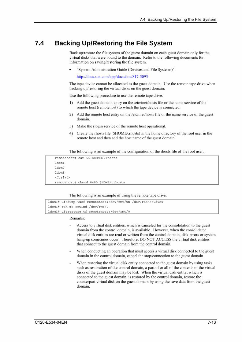
7.4 Backing Up/Restoring the File System
7.4 Backing Up/Restoring the File System Back up/restore the file system of the guest domain on each guest domain only for the virtual disks that were bound to the domain. Refer to the following documents for information on saving/restoring the file system.
• "System Administration Guide (Devices and File Systems)"
http://docs.sun.com/app/docs/doc/817-5093
The tape device cannot be allocated to the guest domain. Use the remote tape drive when backing up/restoring the virtual disks on the guest domain.
Use the following procedure to use the remote tape drive.
1) Add the guest domain entry on the /etc/inet/hosts file or the name service of the remote host (remotehost) to which the tape device is connected.
2) Add the remote host entry on the /etc/inet/hosts file or the name service of the guest domain.
3) Make the rlogin service of the remote host operational.
4) Create the rhosts file ($HOME/.rhosts) in the home directory of the root user in the remote host and then add the host name of the guest domain.
The following is an example of the configuration of the rhosts file of the root user.
remotehost# cat >> $HOME/.rhosts
ldom1
ldom2
ldom3
<Ctrl+d>
remotehost# chmod 0400 $HOME/.rhosts
The following is an example of using the remote tape drive.
ldom1# ufsdump 0ucf remotehost:/dev/rmt/0n /dev/rdsk/c0d0s0
ldom1# rsh mt rewind /dev/rmt/0
ldom1# ufsrestore tf remotehost:/dev/rmt/0
Remarks:
- Access to virtual disk entities, which is canceled for the consolidation to the guest domain from the control domain, is available. However, when the consolidated virtual disk entities are read or written from the control domain, disk errors or system hang-up sometimes occur. Therefore, DO NOT ACCESS the virtual disk entities that connect to the guest domain from the control domain.
- When conducting an operation that must access a virtual disk connected to the guest domain in the control domain, cancel the stop/connection to the guest domain.
- When restoring the virtual disk entity connected to the guest domain by using tasks such as restoration of the control domain, a part of or all of the contents of the virtual disks of the guest domain may be lost. When the virtual disk entity, which is connected to the guest domain, is restored by the control domain, restore the counterpart virtual disk on the guest domain by using the save data from the guest domain.
C120-E534-04EN 7-13

Operating LDoms
7.5 Powering off the Server, Stopping/Rebooting the Control Domain
When turning off the server, or stopping/rebooting the control domain or changing to the single-user mode the control domain, you should stop all guest domains and cancel all connections.
Also, when changing the LDoms configuration for the control domain, be sure to turn off the server itself (RUN level5) and then turn it on again, instead of rebooting (RUN level6) and powering up the server.
1) Stop all of the guest domains. primary# ldm stop -a <Enter>
2) Release the binding to all of the guest domain resources.
Make sure that all of the domains except the control domain are set to "inactive". primary# ldm unbind-domain ldom1 <Enter>
primary# ldm unbind-domain ldom2 <Enter>
primary# ldm unbind-domain ldom3 <Enter>
primary# ldm list<Enter>
NAME STATE FLAGS CONS VCPU MEMORY UTIL UPTIME
primary active -n-cv SP 8 1G 0.1% 3h 19m
ldom1 inactive ----- 16 1920M
ldom2 inactive ----- 16 1G
ldom3 inactive ----- 24 4G
3) The logical domain composition is preserved.
To make changed information effective since the next power on after preserving the logical domain composition referring to "7.7.5 Modification of OBP variables, device-alias etc."
4) Stop (Reboot) the control domain. primary# shutdown -y -g0 -i5 (or 6 or 0) <Enter>
Remarks: When turning off the power, stopping and rebooting the control domain without stopping the guest domain and canceling the resource connection, some failures may occur. For example, the guest domain cannot be started or operation errors occur. In this case, release the resource binding of the guest domain, set the guest domain to "inactive" and reboot the guest domain.
When the guest domain cannot be started primary# ldm stop-domain <domain name><Enter>
primary# ldm unbind-domain <domain name> <Enter>
primary# ldm bind-domain <domain name><Enter>
primary# ldm start-domain <domain name> <Enter>
7-14 C120-E534-04EN

7.5 Powering off the Server, Stopping/Rebooting the Control Domain
If the following message is displayed when the guest domain is stopped, forcibly terminate the domain with the [-f] option.
ldom1 stop timed out, use-f to force it to stop
primary# ldm stop-domain -f <domain name> <Enter>
When a panic is indicated for the guest domain, execute the following command. ldom1 stop timed out, use-f to force it to stop
primary# ldm panic-domain<domain name> <Enter>
C120-E534-04EN 7-15
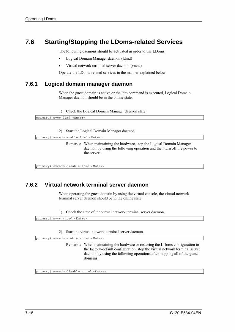
Operating LDoms
7.6 Starting/Stopping the LDoms-related Services The following daemons should be activated in order to use LDoms.
• Logical Domain Manager daemon (ldmd)
• Virtual network terminal server daemon (vntsd)
Operate the LDoms-related services in the manner explained below.
7.6.1 Logical domain manager daemon When the guest domain is active or the ldm command is executed, Logical Domain Manager daemon should be in the online state.
1) Check the Logical Domain Manager daemon state. primary# svcs ldmd <Enter>
2) Start the Logical Domain Manager daemon. primary# svcadm enable ldmd <Enter>
Remarks: When maintaining the hardware, stop the Logical Domain Manager daemon by using the following operation and then turn off the power to the server.
primary# svcadm disable ldmd <Enter>
7.6.2 Virtual network terminal server daemon When operating the guest domain by using the virtual console, the virtual network terminal server daemon should be in the online state.
1) Check the state of the virtual network terminal server daemon. primary# svcs vntsd <Enter>
2) Start the virtual network terminal server daemon. primary# svcadm enable vntsd <Enter>
Remarks: When maintaining the hardware or restoring the LDoms configuration to the factory-default configuration, stop the virtual network terminal server daemon by using the following operations after stopping all of the guest domains.
primary# svcadm disable vntsd <Enter>
7-16 C120-E534-04EN
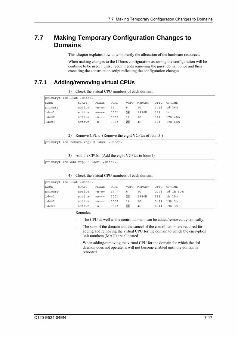
7.7 Making Temporary Configuration Changes to Domains
7.7 Making Temporary Configuration Changes to Domains
This chapter explains how to temporarily the allocation of the hardware resources.
When making changes to the LDoms configuration assuming the configuration will be continue to be used, Fujitsu recommends removing the guest domain once and then executing the construction script reflecting the configuration changes.
7.7.1 Adding/removing virtual CPUs 1) Check the virtual CPU numbers of each domain.
primary# ldm list <Enter>
NAME STATE FLAGS CONS VCPU MEMORY UTIL UPTIME
primary active -n-cv SP 8 1G 3.1% 1d 36m
ldom1 active -n--- 5001 16 1920M 34% 1m
ldom2 active -n--- 5002 16 1G 34% 17h 48m
ldom3 active -n--- 5003 24 4G 17% 17h 48m
2) Remove CPUs. (Remove the eight VCPUs of ldom3.) primary# ldm remove-vcpu 8 ldom3 <Enter>
3) Add the CPUs. (Add the eight VCPUs to ldom1) primary# ldm add-vcpu 8 ldom1 <Enter>
4) Check the virtual CPU numbers of each domain. primary# ldm list <Enter>
NAME STATE FLAGS CONS VCPU MEMORY UTIL UPTIME
primary active -n-cv SP 8 1G 0.2% 1d 1h 50m
ldom1 active -n--- 5001 24 1920M 33% 1h 15m
ldom2 active -n--- 5002 16 1G 0.1% 19h 3m
ldom3 active -n--- 5003 16 4G 0.1% 19h 3m
Remarks:
- The CPU as well as the control domain can be added/removed dynamically.
- The stop of the domain and the cancel of the consolidation are required for adding and removing the virtual CPU for the domain to which the encryption unit numbers (MAU) are allocated.
- When adding/removing the virtual CPU for the domain for which the drd daemon does not operate, it will not become enabled until the domain is rebooted.
C120-E534-04EN 7-17

Operating LDoms
7.7.2 Adding/removing memory Rebooting the domain is required to change the memory.
1) Guest domain
1-1) Check the amount of memory allocated to the domain primary# ldm list <Enter>
NAME STATE FLAGS CONS VCPU MEMORY UTIL UPTIME
primary active -n-cv SP 8 1G 0.7% 1d 5h 59m
ldom1 active -n--- 5001 24 1920M 22% 1m
ldom2 active -n--- 5002 16 1G 0.1% 23h 12m
ldom3 active -n--- 5003 16 4G 36% 23h 12m
1-2) Stop the domain. primary# ldm stop-domain ldom2 <Enter>
primary# ldm stop-domain ldom3 <Enter>
1-3) Remove the domain memory. (Remove the 1GB memory of ldom3.) primary# ldm remove-memory 1G ldom3 <Enter>
Remarks: Addressable units are G (GB), M (MB) and K (KB).
1-4) Add the domain memory. (Add the 1GB memory to ldom2.) primary# ldm add-memory 1G ldom2 <Enter>
Remarks: Addressable units are G (GB), M (MB) and K (KB).
1-5) Start the domain. primary# ldm start-domain ldom3 <Enter>
primary# ldm start-domain ldom2 <Enter>
1-6) Check the memory amount of the domain. primary# ldm list <Enter>
NAME STATE FLAGS CONS VCPU MEMORY UTIL UPTIME
primary active -n-cv SP 8 1G 0.7% 1d 5h 59m
ldom1 active -n--- 5000 8 1920M 22% 1m
ldom2 active -n--- 5001 8 2G 0.1% 23h 12m
ldom3 active -n--- 5002 8 3G 36% 23h 12m
7-18 C120-E534-04EN

7.7 Making Temporary Configuration Changes to Domains
2) Control domain
2-1) Stop all of the domains. primary# ldm stop-domain -a <Enter>
primary# ldm unbind-domain <domain name><Enter>
Remarks: Be sure to stop all of guest domains and release the resource bindings because the changes to the control domain memory require the rebooting of the control domain.
2-2) Check the memory amount of the control domain. primary# ldm list primary <Enter>
NAME STATE FLAGS CONS VCPU MEMORY UTIL UPTIME
primary active -n-cv SP 8 1G 0.2% 1d 5h 54m
2-3) Add the memory to the control domain. primary# ldm add-memory 1G primary <Enter>
Initiating delayed reconfigure operation on LDom primary. All configuration
changes for other LDoms are disabled until the LDom reboots, at which time
the new configuration for LDom primary will also take effect.
2-4) Reboot the control domain. primary# shutdown -y -g0 -i6 <Enter>
2-5) Check the memory amount of the domain. primary# ldm list primary <Enter>
NAME STATE FLAGS CONS VCPU MEMORY UTIL UPTIME
primary active -n-cv SP 8 2G 0.2% 6m
C120-E534-04EN 7-19
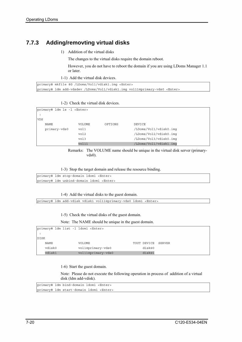
Operating LDoms
7.7.3 Adding/removting virtual disks 1) Addition of the virtual disks
The changes to the virtual disks require the domain reboot.
However, you do not have to reboot the domain if you are using LDoms Manager 1.1 or later.
1-1) Add the virtual disk devices. primary# mkfile 8G /LDoms/Vol1/vdisk1.img <Enter>
primary# ldm add-vdsdev /LDoms/Vol1/vdisk1.img vol11@primary-vds0 <Enter>
1-2) Check the virtual disk devices. primary# ldm ls -l <Enter>
:
VDS
NAME VOLUME OPTIONS DEVICE
primary-vds0 vol1 /LDoms/Vol1/vdisk0.img
vol2 /LDoms/Vol2/vdisk0.img
vol3 /LDoms/Vol3/vdisk0.img
vol11 /LDoms/Vol1/vdisk1.img
Remarks: The VOLUME name should be unique in the virtual disk server (primary-vds0).
1-3) Stop the target domain and release the resource binding. primary# ldm stop-domain ldom1 <Enter>
primary# ldm unbind-domain ldom1 <Enter>
1-4) Add the virtual disks to the guest domain. primary# ldm add-vdisk vdisk1 vol11@primary-vds0 ldom1 <Enter>
1-5) Check the virtual disks of the guest domain.
Note: The NAME should be unique in the guest domain. primary# ldm list -l ldom1 <Enter>
:
DISK
NAME VOLUME TOUT DEVICE SERVER
vdisk0 vol1@primary-vds0 disk@0
vdisk1 vol11@primary-vds0 disk@1
1-6) Start the guest domain.
Note: Please do not execute the following operation in process of addition of a virtual disk (ldm add-vdisk).
primary# ldm bind-domain ldom1 <Enter>
primary# ldm start-domain ldom1 <Enter>
7-20 C120-E534-04EN

7.7 Making Temporary Configuration Changes to Domains
1-7) Reconfigure the device after logging into the domain. ldom1# devfsadm <Enter>
Remarks: Starting the domain by boot -r (the device reconfiguration) from the OBP prompt is enabled.
1-8) Check the disks. ldom1# format <Enter>
Searching for disks...done
AVAILABLE DISK SELECTIONS:
0. c0d0 <SUNVDSK cyl 41941 alt 2 hd 1 sec 600>
/virtual-devices@100/channel-devices@200/disk@0
1. c0d1 <SUNVDSK cyl 339 alt 2 hd 1 sec 600>
/virtual-devices@100/channel-devices@200/disk@1
Specify disk (enter its number):
2) Removing the virtual disks
Rebooting the domain is required for the virtual disks.
However, you do not have to reboot the domain if you are using LDoms Manager 1.1 or later.
2-1) Check the virtual disk devices. primary# ldm list -l ldom1 <Enter>
:
DISK
NAME VOLUME TOUT DEVICE SERVER
vdisk0 vol1@primary-vds0 disk@0
vdisk1 vol11@primary-vds0 disk@1
2-2) Stop the target domain and release the resource binding. primary# ldm stop-domain ldom1 <Enter>
primary# ldm unbind-domain ldom1 <Enter>
2-3) Remove the virtual disk from the guest domain. primary# ldm remove-vdisk vdisk1 ldom1 <Enter>
When removing the virtual disk device primary# ldm remove-vdsdev vol11@primary-vds0 <Enter>
2-4) Start the guest domain. primary# ldm bind-domain ldom1 <Enter>
primary# ldm start-domain ldom1 <Enter>
C120-E534-04EN 7-21
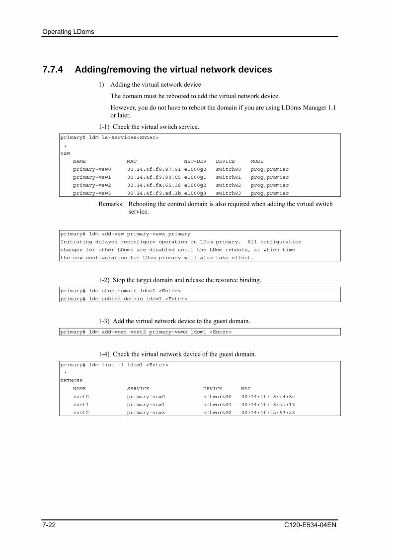
Operating LDoms
7.7.4 Adding/removing the virtual network devices 1) Adding the virtual network device
The domain must be rebooted to add the virtual network device.
However, you do not have to reboot the domain if you are using LDoms Manager 1.1 or later.
1-1) Check the virtual switch service. primary# ldm ls-services<Enter>
:
VSW
NAME MAC NET-DEV DEVICE MODE
primary-vsw0 00:14:4f:f8:97:91 e1000g0 switch@0 prog,promisc
primary-vsw1 00:14:4f:f9:90:05 e1000g1 switch@1 prog,promisc
primary-vsw2 00:14:4f:fa:65:18 e1000g2 switch@2 prog,promisc
primary-vsw3 00:14:4f:f9:ad:3b e1000g3 switch@3 prog,promisc
Remarks: Rebooting the control domain is also required when adding the virtual switch service.
primary# ldm add-vsw primary-vswx primary
Initiating delayed reconfigure operation on LDom primary. All configuration
changes for other LDoms are disabled until the LDom reboots, at which time
the new configuration for LDom primary will also take effect.
1-2) Stop the target domain and release the resource binding. primary# ldm stop-domain ldom1 <Enter>
primary# ldm unbind-domain ldom1 <Enter>
1-3) Add the virtual network device to the guest domain. primary# ldm add-vnet vnet2 primary-vswx ldom1 <Enter>
1-4) Check the virtual network device of the guest domain. primary# ldm list -l ldom1 <Enter>
:
NETWORK
NAME SERVICE DEVICE MAC
vnet0 primary-vsw0 network@0 00:14:4f:f8:b4:8c
vnet1 primary-vsw1 network@1 00:14:4f:f8:dd:13
vnet2 primary-vswx network@2 00:14:4f:fa:63:a3
7-22 C120-E534-04EN
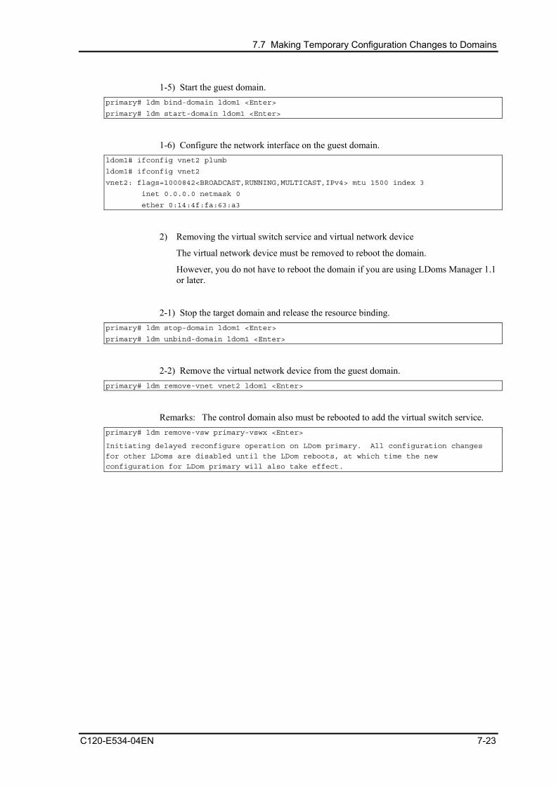
7.7 Making Temporary Configuration Changes to Domains
1-5) Start the guest domain. primary# ldm bind-domain ldom1 <Enter>
primary# ldm start-domain ldom1 <Enter>
1-6) Configure the network interface on the guest domain. ldom1# ifconfig vnet2 plumb
ldom1# ifconfig vnet2
vnet2: flags=1000842<BROADCAST,RUNNING,MULTICAST,IPv4> mtu 1500 index 3
inet 0.0.0.0 netmask 0
ether 0:14:4f:fa:63:a3
2) Removing the virtual switch service and virtual network device
The virtual network device must be removed to reboot the domain.
However, you do not have to reboot the domain if you are using LDoms Manager 1.1 or later.
2-1) Stop the target domain and release the resource binding. primary# ldm stop-domain ldom1 <Enter>
primary# ldm unbind-domain ldom1 <Enter>
2-2) Remove the virtual network device from the guest domain. primary# ldm remove-vnet vnet2 ldom1 <Enter>
Remarks: The control domain also must be rebooted to add the virtual switch service. primary# ldm remove-vsw primary-vswx <Enter>
Initiating delayed reconfigure operation on LDom primary. All configuration changes
for other LDoms are disabled until the LDom reboots, at which time the new
configuration for LDom primary will also take effect.
C120-E534-04EN 7-23

Operating LDoms
2-3) Start the guest domain. primary# ldm list -l ldom1 <Enter>
...
NETWORK
NAME SERVICE DEVICE MAC
vnet0 primary-vsw0@primary network@0 00:14:4f:f8:b4:8c
vnet1 primary-vsw1@primary network@1 00:14:4f:f8:dd:13
DISK
NAME VOLUME TOUT DEVICE SERVER
vdisk0 vol1@primary-vds0 disk@0 primary
VCONS
NAME SERVICE PORT
ldom1 primary-vcc0@primary 5001
primary# ldm bind-domain ldom1 <Enter>
primary# ldm start-domain ldom1 <Enter>
7.7.5 Modification of OBP variables, device-alias etc. If you modified OBP variables, device-alias etc. of the control domain, the modification does not become effective at the next power on. Before powering off the machine, the modification needs to be reflected to the configuration information. Also it is recommended that you should reflect it in configuration script of the control domain. When the states of guest domain is changed, it is necessary to reflect it in composition information. Example) When you change the boot disk to "disk3"
primary# eeprom boot-device=disk3 primary# ldm remove-config initial primary# ldm add-config initial primary# ldm list-config factory-default initial [current] primary# shutdown -i0 -g0 -y ok> power-off
The following operation differs depending on the system monitoring mechanisms (ALOM, ILOM). Follow the procedure for your system monitoring mechanism. 【ALOM】
sc> poweron –c
【ILOM】
-> start /SYS Are you sure you want to start /SYS (y/n)? y Starting /SYS
7-24 C120-E534-04EN

7.8 Collecting/Restoring the Configuration Information of the Guest Domain
7.8 Collecting/Restoring the Configuration Information of the Guest Domain
This chapter explains how to collect the configuration information of the guest domain and restore the guest domain that uses the information.
7.8.1 Collecting the configuration information of the guest domain
1) The following indicates how to collect the configuration information of the guest domain. (In this example, the configuration information of ldom1 is stored in /LDoms/Domains/.)
primary$ ldm list-constraints -x ldom1 > /LDoms/Domains/ldom1.xml <Enter>
Remarks:
- The configuration file is created in xml format
- Perform the above for all of the domains whenever the configuration is changed.
- Copy the information in the DVD-R, tapes or file servers to be prepared in case they are lost from the disk
7.8.2 Restoring the guest domain The guest domain, whose configuration is changed temporarily, can be restored to the configuration in effect at the point where such configuration information was collected.
1) Removing the guest domain
Stop the guest domain that you want to reconfigure, release the binding and then remove it.
primary$ ldm list <Enter>
NAME STATE FLAGS CONS VCPU MEMORY UTIL UPTIME
primary active -n-cv SP 8 1G 0.3% 21h 34m
ldom1 inactive ----- 4 1G
primary$ ldm remove-domain ldom1 <Enter>
primary$ ldm list <Enter>
NAME STATE FLAGS CONS VCPU MEMORY UTIL UPTIME
primary active -n-cv SP 8 1G 0.3% 21h 34m
Remarks: Even if you remove the virtual disk content, it's contains remains available because it has been saved, and can therefore be reused.
2) Rebuilding the guest domain
2-1) Rebuild the guest domain by using the saved xml file. primary$ ldm add-domain -i /LDoms/Domains/ldom1.xml <Enter>
C120-E534-04EN 7-25
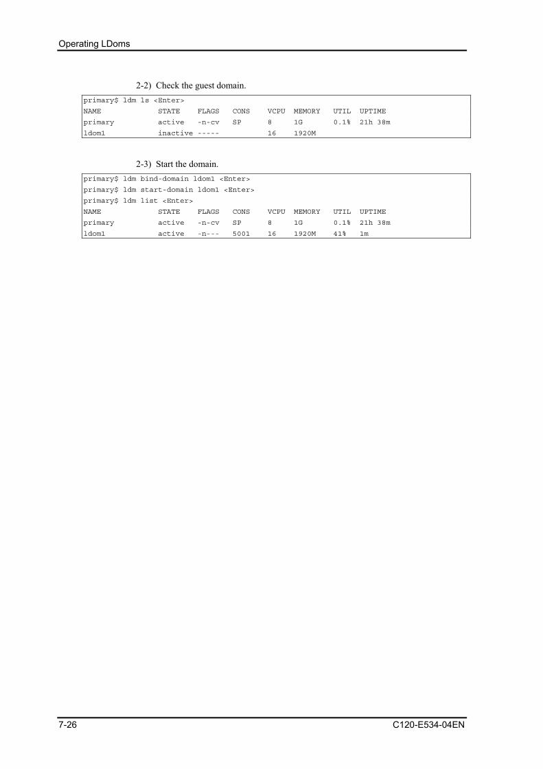
Operating LDoms
2-2) Check the guest domain. primary$ ldm ls <Enter>
NAME STATE FLAGS CONS VCPU MEMORY UTIL UPTIME
primary active -n-cv SP 8 1G 0.1% 21h 38m
ldom1 inactive ----- 16 1920M
2-3) Start the domain. primary$ ldm bind-domain ldom1 <Enter>
primary$ ldm start-domain ldom1 <Enter>
primary$ ldm list <Enter>
NAME STATE FLAGS CONS VCPU MEMORY UTIL UPTIME
primary active -n-cv SP 8 1G 0.1% 21h 38m
ldom1 active -n--- 5001 16 1920M 41% 1m
7-26 C120-E534-04EN

7.9 Replacing the LDoms Configuration from the Control Domain
7.9 Replacing the LDoms Configuration from the Control Domain
The LDoms configuration is stored in the system controller (SC), and is read after power activation or reset. Several LDoms configurations are available for replacement purposes.
In order to operate the degraded hardware temporarily in a different LDoms configuration, this function is used when the LDoms environment is rebuilt in a degraded environment and operated again using the original configuration after hardware restoration.
1) Check the in-use configuration.
The following is an example of the output from LDoms Manager 1.0.3. primary# ldm list-spconfig <Enter>
factory-default
initial
reduced [current]
Remarks: In this example, [reduced] is the in-use LDoms environment.
2) Stop the guest domain and release the binding. primary# ldm stop -a <Enter>
primary# ldm unbind <domain name> <Enter>
3) Specify the configuration you want to replace. primary# ldm set-spconfig initial <Enter>
4) Check the configuration again. primary# ldm list-spconfig <Enter>
factory-default
initial [next]
reduced [current]
Remarks: The configuration with [next] is executed after the reboot.
5) Activate the power again. primary# shutdown -y -g0 -i5 <Enter>
...
sc> poweron -c
C120-E534-04EN 7-27
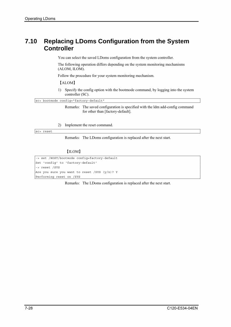
Operating LDoms
7.10 Replacing LDoms Configuration from the System Controller
You can select the saved LDoms configuration from the system controller.
The following operation differs depending on the system monitoring mechanisms (ALOM, ILOM).
Follow the procedure for your system monitoring mechanism.
【ALOM】
1) Specify the config option with the bootmode command, by logging into the system controller (SC).
sc> bootmode config="factory-default"
Remarks: The saved configuration is specified with the ldm add-config command for other than [factory-default].
2) Implement the reset command. sc> reset
Remarks: The LDoms configuration is replaced after the next start.
【ILOM】 -> set /HOST/bootmode config=factory-default
Set 'config' to 'factory-default'
-> reset /SYS
Are you sure you want to reset /SYS (y/n)? Y
Performing reset on /SYS
Remarks: The LDoms configuration is replaced after the next start.
7-28 C120-E534-04EN

7.11 How to Remove the LDoms Environment
7.11 How to Remove the LDoms Environment The following indicates the procedure for creating the environment in which the OS and system controller do not use the LDoms.
7.11.1 Removing the guest domain 1) Stop all of the guest domains.
ldom1# shutdown -i0 -g0 -y <Enter> ldom2# shutdown -i0 -g0 -y <Enter> ldom3# shutdown -i0 -g0 -y <Enter> primary# ldm stop-domain –a <Enter>
2) Remove the connections of all of the guest domains. primary# ldm unbind <domain name> <Enter>
3) Remove all of the guest domains. primary# ldm remove-domain <domain name> <Enter>
7.11.2 Removing the LDoms configuration 1) Set the LDoms configuration to the factory-default.
primary# ldm set-config factory-default <Enter>
2) Remove all of the saved LDoms configurations. primary# ldm list-config <Enter>
primary# ldm remove-config <config name > <Enter>
...
3) Reconfirm the configurations.
The following is an example of the output from LDoms Manager 1.0.3. primary# ldm list-config <Enter>
factory-default [next]
Remarks: You cannot remove [factory-default] (the factory default configuration).
4) Restore the network definition file if the file was changed in [5.3.2 Connection to the control domain].
primary# mv /etc/hostname.vsw0 /etc/hostname.e1000g0 <Enter>
5) Stop the vntsd service. primary# svcadm -v disable vntsd <Enter>
svc:/ldoms/vntsd:default is disabled.
primary# svcs -a |grep ldom
disabled 8:36:20 svc:/ldoms/vntsd:default
C120-E534-04EN 7-29

Operating LDoms
online 8:32:59 svc:/ldoms/ldmd:default
6) Turn off the power to the server and then reboot it. primary# shutdown -y -g0 -i5 <Enter>
...
sc> poweron -c
Remarks: You can get the same result even if you implement the reset command on the system controller (SC).
7.12 How to Remove and Re-install the LDoms The following describes how to remove and reinstall LDoms. You can use the same procedure when upgrading LDoms.
7.12.1 Removing the guest domain 1) Stop all of the guest domains.
ldom1# shutdown -i0 -g0 -y <Enter> ldom2# shutdown -i0 -g0 -y <Enter> ldom3# shutdown -i0 -g0 -y <Enter> primary# ldm stop-domain –a <Enter>
2) Remove the connections of all of the guest domains. primary# ldm unbind <domain name> <Enter>
3) Remove all of the guest domains. primary# ldm remove-domain <domain name> <Enter>
7.12.2 Removing the LDoms configuration 1) Set the LDoms configuration to the factory-default.
primary# ldm set-config factory-default <Enter>
2) Remove all of the saved LDoms configurations. primary# ldm list-config <Enter>
primary# ldm remove-config <config name > <Enter>
...
2) Reconfirm the configurations.
The following is an example of the output from LDoms Manager 1.0.3. primary# ldm list-config <Enter>
factory-default [next]
Remarks: You cannot remove [factory-default] (the factory default configuration).
7-30 C120-E534-04EN
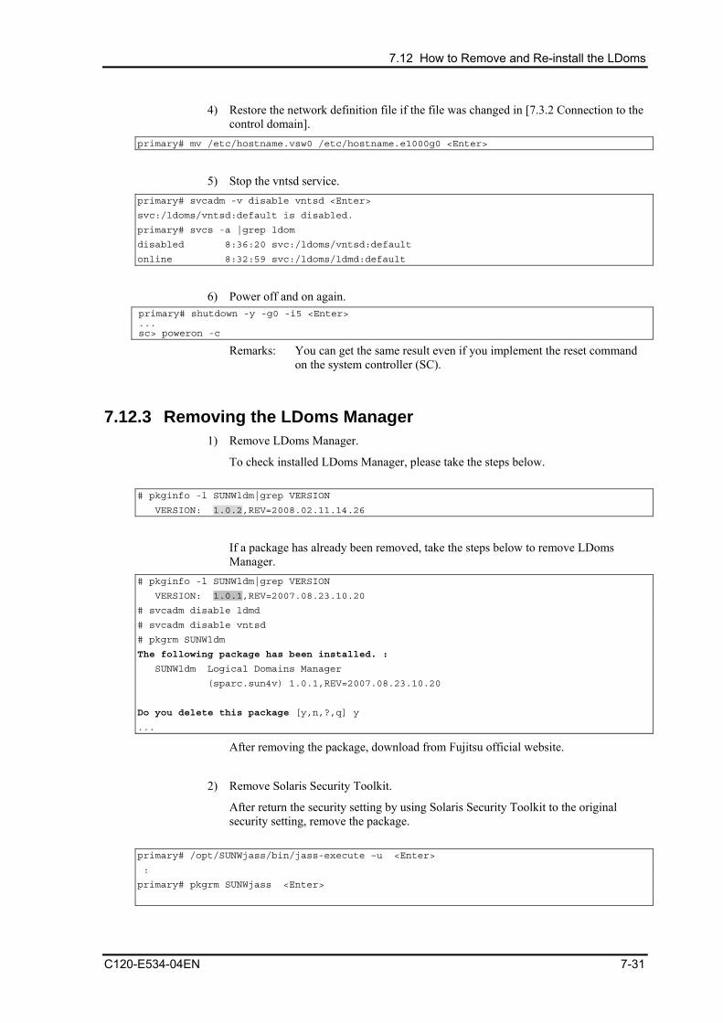
7.12 How to Remove and Re-install the LDoms
4) Restore the network definition file if the file was changed in [7.3.2 Connection to the control domain].
primary# mv /etc/hostname.vsw0 /etc/hostname.e1000g0 <Enter>
5) Stop the vntsd service.
primary# svcadm -v disable vntsd <Enter>
svc:/ldoms/vntsd:default is disabled.
primary# svcs -a |grep ldom
disabled 8:36:20 svc:/ldoms/vntsd:default
online 8:32:59 svc:/ldoms/ldmd:default
6) Power off and on again.
primary# shutdown -y -g0 -i5 <Enter> ... sc> poweron -c
Remarks: You can get the same result even if you implement the reset command on the system controller (SC).
7.12.3 Removing the LDoms Manager 1) Remove LDoms Manager.
To check installed LDoms Manager, please take the steps below.
# pkginfo -l SUNWldm|grep VERSION
VERSION: 1.0.2,REV=2008.02.11.14.26
If a package has already been removed, take the steps below to remove LDoms Manager.
# pkginfo -l SUNWldm|grep VERSION
VERSION: 1.0.1,REV=2007.08.23.10.20
# svcadm disable ldmd
# svcadm disable vntsd
# pkgrm SUNWldm
The following package has been installed. :
SUNWldm Logical Domains Manager
(sparc.sun4v) 1.0.1,REV=2007.08.23.10.20
Do you delete this package [y,n,?,q] y
...
After removing the package, download from Fujitsu official website.
2) Remove Solaris Security Toolkit.
After return the security setting by using Solaris Security Toolkit to the original security setting, remove the package.
primary# /opt/SUNWjass/bin/jass-execute –u <Enter>
:
primary# pkgrm SUNWjass <Enter>
C120-E534-04EN 7-31

Operating LDoms
7-32 C120-E534-04EN
primary# /usr/sbin/shutdown -i6 -g0 –y <Enter>
7.12.4 Installing the LDoms Manager Make sure that OS, patch level, and firm level meet the requirement of LDoms Manager that you are going to install.
Apply the latest recommended & security patches, and regular PTF.
Refer to “6.3 Installing LDoms Manager” to install the new package.
7.12.5 Building the domains Refer to “4.6/5.9 Building the Control Domain”, and “4.7/5.11 Building the Guest Domain” to build each domain.
1) Confirm the state of all domains after creating them. primary$ ldm list <Enter>
NAME STATE FLAGS CONS VCPU MEMORY UTIL UPTIME
primary active -n-cv SP 8 1G 0.6% 52m
ldom1 active -n--- 5001 16 1920M 0.0% 36m
ldom2 bound -t--- 5002 16 1G 6.2% 4m
ldom3 inactive -n-- 5003 24 4G 100% 52m
For more information, please refer to “7.1.1 Confirming the state of the domain”.
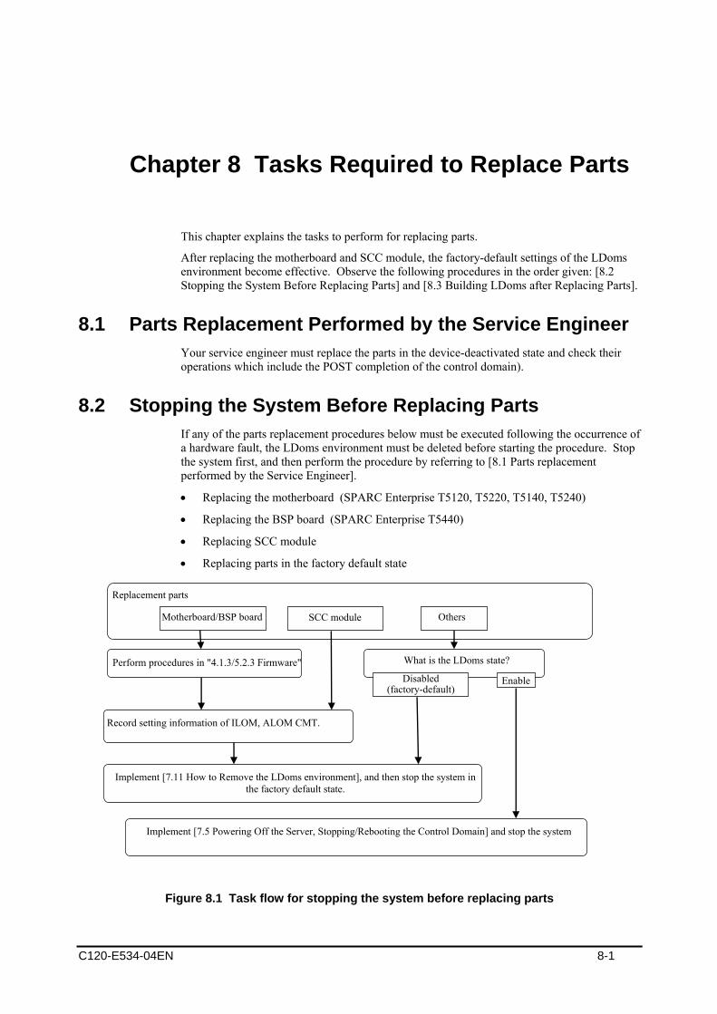
C120-E534-04EN 8-1
Chapter 8 Tasks Required to Replace Parts
This chapter explains the tasks to perform for replacing parts.
After replacing the motherboard and SCC module, the factory-default settings of the LDoms environment become effective. Observe the following procedures in the order given: [8.2 Stopping the System Before Replacing Parts] and [8.3 Building LDoms after Replacing Parts].
8.1 Parts Replacement Performed by the Service Engineer Your service engineer must replace the parts in the device-deactivated state and check their operations which include the POST completion of the control domain).
8.2 Stopping the System Before Replacing Parts If any of the parts replacement procedures below must be executed following the occurrence of a hardware fault, the LDoms environment must be deleted before starting the procedure. Stop the system first, and then perform the procedure by referring to [8.1 Parts replacement performed by the Service Engineer].
• Replacing the motherboard (SPARC Enterprise T5120, T5220, T5140, T5240)
• Replacing the BSP board (SPARC Enterprise T5440)
• Replacing SCC module
• Replacing parts in the factory default state
Figure 8.1 Task flow for stopping the system before replacing parts
Replacement parts
Motherboard/BSP board
What is the LDoms state?
Enable Disabled(factory-default)
Perform procedures in "4.1.3/5.2.3 Firmware"
Implement [7.11 How to Remove the LDoms environment], and then stop the system in the factory default state.
Implement [7.5 Powering Off the Server, Stopping/Rebooting the Control Domain] and stop the system
SCC module Others
Record setting information of ILOM, ALOM CMT.

Tasks Required to Replace Parts
8.3 Building LDoms after Replacing Parts LDoms must be rebuilt when the LDoms environment enters the factory-default state. Refer to [Figure 8.2 Tasks flow for Building LDoms after Replacing Parts] for information on building the LDoms environment.
• Notes
1) The MAC addresses of the guest domain (HostID), virtual switch (vsw) or virtual network (vnet), which are automatically allocated, may be changed.
2) The X part of the virtual switch (vswX), the virtual network (vnetX), and the virtual disk (c0dXs0) may also be changed.
Replacement parts Motherboard/BSP board SCC modules Others
LDoms state?
Disabled (factory-default)
Is system firmware upgrade required?
No Yes
Stop the system by implementing [7.5 Powering off the Server, Stopping/
Rebooting the Control Domain
Restore the setting information of ILOM, ALOM CMT you recorded.
Implement [4.6/5.9 Building the Control Domain]. If needed, implement [7.3.2 Connection to the control domain].
Implement [4.7/5.11 Building the Guest Domain].
Yes
Implement [6.1 Upgrading Firmware].
Stop the system by [7.11 How to Delete the LDoms Environment]? Yes No (including abnormal termination)
Delete all of the guest domains and stored LDoms configurations.
factory-default factory-default
Enabled
No (including abnormal termination)
Implement [7.1.4 Stopping the domain from the control
domain].
Implement [7.1.2 Startingthe domain].
Implement [7.8. Collecting/Restoring the Configuration Information of the Guest Domain].
Figure 8.2 Tasks flow for Building LDoms after Replacing Parts
8-2 C120-E534-04EN
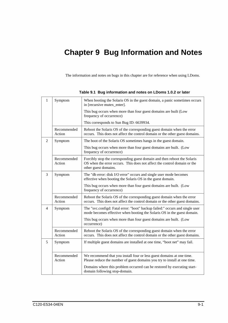
C120-E534-04EN 9-1
Chapter 9 Bug Information and Notes
The information and notes on bugs in this chapter are for reference when using LDoms.
Table 9.1 Bug information and notes on LDoms 1.0.2 or later
Symptom When booting the Solaris OS in the guest domain, a panic sometimes occurs in [recursive mutex_enter].
This bug occurs when more than four guest domains are built (Low frequency of occurrence)
This corresponds to Sun Bug ID: 6639934.
1
Recommended Action
Reboot the Solaris OS of the corresponding guest domain when the error occurs. This does not affect the control domain or the other guest domains.
Symptom The boot of the Solaris OS sometimes hangs in the guest domain.
This bug occurs when more than four guest domains are built. (Low frequency of occurrence)
2
Recommended Action
Forcibly stop the corresponding guest domain and then reboot the Solaris OS when the error occurs. This does not affect the control domain or the other guest domains.
Symptom The "db error: disk I/O error" occurs and single user mode becomes effective when booting the Solaris OS in the guest domain.
This bug occurs when more than four guest domains are built. (Low frequency of occurrence)
3
Recommended Action
Reboot the Solaris OS of the corresponding guest domain when the error occurs. This does not affect the control domain or the other guest domains.
Symptom The "svc.configd: Fatal error: "boot" backup failed:" occurs and single user mode becomes effective when booting the Solaris OS in the guest domain.
This bug occurs when more than four guest domains are built. (Low occurrence)
4
Recommended Action
Reboot the Solaris OS of the corresponding guest domain when the error occurs. This does not affect the control domain or the other guest domains.
Symptom
If multiple guest domains are installed at one time, “boot net” may fail. 5
Recommended Action
We recommend that you install four or less guest domains at one time. Please reduce the number of guest domains you try to install at one time.
Domains where this problem occurred can be restored by executing start-domain following stop-domain.
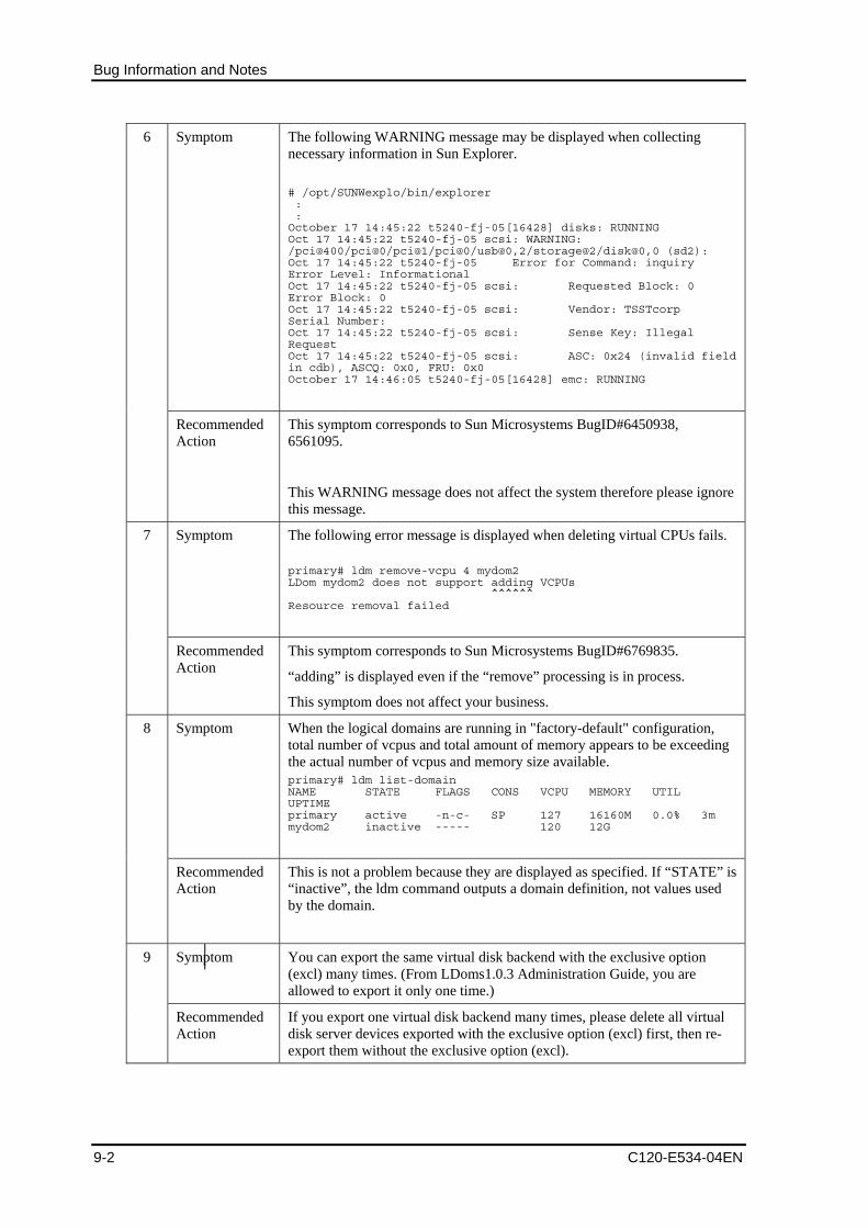
Bug Information and Notes
9-2 C120-E534-04EN
Symptom The following WARNING message may be displayed when collecting necessary information in Sun Explorer.
# /opt/SUNWexplo/bin/explorer : : October 17 14:45:22 t5240-fj-05[16428] disks: RUNNING Oct 17 14:45:22 t5240-fj-05 scsi: WARNING: /pci@400/pci@0/pci@1/pci@0/usb@0,2/storage@2/disk@0,0 (sd2): Oct 17 14:45:22 t5240-fj-05 Error for Command: inquiry Error Level: Informational Oct 17 14:45:22 t5240-fj-05 scsi: Requested Block: 0 Error Block: 0 Oct 17 14:45:22 t5240-fj-05 scsi: Vendor: TSSTcorp Serial Number: Oct 17 14:45:22 t5240-fj-05 scsi: Sense Key: Illegal Request Oct 17 14:45:22 t5240-fj-05 scsi: ASC: 0x24 (invalid field in cdb), ASCQ: 0x0, FRU: 0x0 October 17 14:46:05 t5240-fj-05[16428] emc: RUNNING
6
Recommended Action
This symptom corresponds to Sun Microsystems BugID#6450938, 6561095.
This WARNING message does not affect the system therefore please ignore this message.
Symptom
The following error message is displayed when deleting virtual CPUs fails. primary# ldm remove-vcpu 4 mydom2 LDom mydom2 does not support adding VCPUs ^^^^^^ Resource removal failed
7
Recommended Action
This symptom corresponds to Sun Microsystems BugID#6769835.
“adding” is displayed even if the “remove” processing is in process.
This symptom does not affect your business.
Symptom When the logical domains are running in "factory-default" configuration, total number of vcpus and total amount of memory appears to be exceeding the actual number of vcpus and memory size available. primary# ldm list-domain NAME STATE FLAGS CONS VCPU MEMORY UTIL UPTIME primary active -n-c- SP 127 16160M 0.0% 3m mydom2 inactive ----- 120 12G
8
Recommended Action
This is not a problem because they are displayed as specified. If “STATE” is “inactive”, the ldm command outputs a domain definition, not values used by the domain.
Symptom You can export the same virtual disk backend with the exclusive option (excl) many times. (From LDoms1.0.3 Administration Guide, you are allowed to export it only one time.)
9
Recommended Action
If you export one virtual disk backend many times, please delete all virtual disk server devices exported with the exclusive option (excl) first, then re-export them without the exclusive option (excl).

Bug Information and Notes
C120-E534-04EN 9-3
Symptom In the Solaris 10 10/08 environment, even if you exported with the slice option that creates one slice disk, slices between s0 and s7 are created after allocating to a guest domain.
10
Recommended Action
Slices between s0 and s7 are created, but since only s0 is available actually, please ignore the slices between s1 and s7.
Symptom If you execute the eject (1) from the control domain, a media may be ejected even though a CD/DVD is in use on a guest domain.
11
Recommended Action
Please specify the exclusive option (excl) when exporting the CD/DVD.
By specifying the exclusive option, the eject (1) from the control domain becomes invalid.
Please use the eject button of the CD/DVD drive to eject a media.
Symptom If you use an exported CD/DVD in a guest domain, you may fail to eject a media even though you press the eject button of the CD/DVD drive.
12
Recommended Action
You need to cancel the allocation of the exported CD/DVD to the guest domain.
To cancel the allocation, you need to stop the guest domain after deleting the virtual disk from the guest domain.
Symptom If you install Solaris OS into the guest domain via network, the system may hang during the guest domain OS boot.
13
Recommended Action
This corresponds to Sun Microsystems BugID #6705823.
6705823 guest ldom hangs during boot net of s10u4
Please apply 127111-05 or later to mini root of the install image.
Symptom When the two or more virtual consoles are added, the telnet connection cannot be established to the newly added virtual console ports.
14
Recommended Action
Only a single virtual console service should exist.
Please do not create more than one virtual console service.
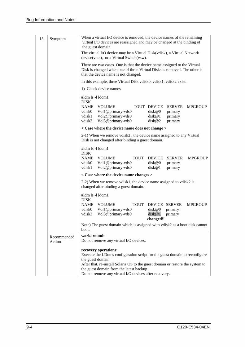
Bug Information and Notes
9-4 C120-E534-04EN
Symptom When a virtual I/O device is removed, the device names of the remaining virtual I/O devices are reassigned and may be changed at the binding of the guest domain. The virtual I/O device may be a Virtual Disk(vdisk), a Virtual Network device(vnet), or a Virtual Switch(vsw).
There are two cases. One is that the device name assigned to the Virtual Disk is changed when one of three Virtual Disks is removed. The other is that the device name is not changed.
In this example, three Virtual Disk vdisk0, vdisk1, vdisk2 exist.
1) Check device names.
#ldm ls -l ldom1 DISK NAME VOLUME TOUT DEVICE SERVER MPGROUPvdisk0 Vol1@primary-vds0 disk@0 primary vdisk1 Vol2@primary-vds0 disk@1 primary vdisk2 Vol3@primary-vds0 disk@2 primary
< Case where the device name does not change >
2-1) When we remove vdisk2 , the device name assigned to any Virtual Disk is not changed after binding a guest domain.
#ldm ls -l ldom1 DISK NAME VOLUME TOUT DEVICE SERVER MPGROUPvdisk0 Vol1@primary-vds0 disk@0 primary vdisk1 Vol2@primary-vds0 disk@1 primary
< Case where the device name changes >
2-2) When we remove vdisk1, the device name assigned to vdisk2 is changed after binding a guest domain.
#ldm ls -l ldom1 DISK NAME VOLUME TOUT DEVICE SERVER MPGROUPvdisk0 Vol1@primary-vds0 disk@0 primary vdisk2 Vol3@primary-vds0 disk@1 primary
changed!! Note) The guest domain which is assigned with vdisk2 as a boot disk cannot boot.
15
Recommended Action
workaround: Do not remove any virtual I/O devices. recovery operations: Execute the LDoms configuration script for the guest domain to reconfigure the guest domain. After that, re-install Solaris OS to the guest domain or restore the system to the guest domain from the latest backup. Do not remove any virtual I/O devices after recovery.
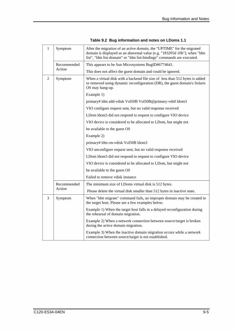
Bug Information and Notes
C120-E534-04EN 9-5
Table 9.2 Bug information and notes on LDoms 1.1
Symptom After the migration of an active domain, the "UPTIME" for the migrated domain is displayed as an abnormal value (e.g. "183205d 10h"), when "ldm list", "ldm list-domain" or "ldm list-bindings" commands are executed.
1
Recommended Action
This appears to be Sun Microsystems BugID#6774641.
This does not affect the guest domain and could be ignored.
Symptom When a virtual disk with a backend file size of less than 512 bytes is added or removed using dynamic reconfiguration (DR), the guest domain's Solaris OS may hang-up.
Example 1)
primary# ldm add-vdisk Vol50B Vol50B@primary-vds0 ldom3
VIO configure request sent, but no valid response received
LDom ldom3 did not respond to request to configure VIO device
VIO device is considered to be allocated to LDom, but might not
be available to the guest OS
Example 2)
primary# ldm rm-vdisk Vol50B ldom3
VIO unconfigure request sent, but no valid response received
LDom ldom3 did not respond to request to configure VIO device
VIO device is considered to be allocated to LDom, but might not
be available to the guest OS
Failed to remove vdisk instance
2
Recommended Action
The minimum size of LDoms virtual disk is 512 bytes.
Please delete the virtual disk smaller than 512 bytes in inactive state.
3 Symptom When "ldm migrate" command fails, an improper domain may be created in the target host. Please see a few examples below.
Example 1) When the target host falls in a delayed reconfiguration during the rehearsal of domain migration.
Example 2) When a network connection between source/target is broken during the active domain migration.
Example 3) When the inactive domain migration occurs while a network connection between source/target is not established.

Bug Information and Notes
9-6 C120-E534-04EN
Recommended Action
Regarding Example 1:
This phenomenon on the delayed reconfiguration corresponds to Sun Microsystems Bug ID#6787570.
During the rehearsal of migration, please do not execute the operation that activates the reconfiguration. If the migration fails, get rid of the cause of the failure in the first place. Then, please remove domains created in the target host manually.
Regarding Example 2, 3:
If the migration fails, please get rid of the cause of the failure such as network trouble. After that, please take the steps below.
・Remove the source domain manually if the target domain is resumed.
・In other cases, remove both source and target domains manually, and rebuild the source domain in the source host.
Symptom The following passage is from "Logical Domains (LDoms) 1.1 Administration Guide" of Sun Microsystems.
"You cannot migrate a logical domain that has bound cryptographic units. Attempts to migrate such a domain fail."
However, when number of VCPU is 1, this migration does not fail.
4
Recommended Action
This is a mistake of "Logical Domains (LDoms) 1.1 Administration Guide".
Correctly, you can not migrate an active domain binding cryptographic units if it has more than one VCPU. This phenomenon corresponds to Sun Microsystems BugID#6843096.
"6843096 LDoms document info is not accurate in customer environment"
Symptom When migrating a logical domain having a vnet device for which hybrid mode is set, the hybrid mode setting of the vnet device of the migrated domain is removed.
5
Recommended Action
This problem corresponds to Sun Microsystems BugID#6844212.
"6844212 Hybrid mode disabled after migrated the domain"
If the hybrid mode setting is required in the target host after the migration of the domain, use the following command to set the hybrid mode for the vnet device of the target domain.
# ldm set-vnet mode=hybrid <I/F name> <ldom name>
Symptom After performing an active domain migration, the system time of the migrated domain will have a delay.
6
Recommended Action
Please fix the time error using the "date" command if necessary.
# date mmddHHMM[[cc] yy] [.SS]
Please refer to the man pages for the details of "date".
Symptom If the network connection between source and target host is disconnected during an active domain migration, the migration fails and the number of the vcpu of the source domain is reduced to 1.
7
Recommended Action
After rebooting the source domain, execute the following command to modify the number of vcpu.
# ldm add-vcpu <vcpu number> <ldom name>

Bug Information and Notes
C120-E534-04EN 9-7
Symptom In LDoms 1.0.3 or older, the configuration status showed [current] even if the current configuration was changed by executing 'ldm bind' command.
In LDoms 1.1, however, the configuration status would change to [next poweron] when the same command 'ldm bind' is executed causing modification in the current configuration.
8
Recommended Action
No action is required because this is the specification of LDoms 1.1.
To save the current configuration, please take necessary steps to save it after removing the current configuration information. If [current] is displayed, you can know the current configuration corresponds with the saved configuration information. Also the appearance of [next poweron] tells you that the current configuration does not correspond with the saved configuration information.
Symptom When you export SVM volume as back-end by using the slice option, a label of the virtual disk allocated to the guest domain is displayed as "<drive type unknown>" by executing the format(1M) from the guest domain.
9
Recommended Action
The displayed information is wrong. But this has no effect on the system behavior.
Symptom When you export zfs volume as back-end by using the slice option, a label of the virtual disk allocated to the guest domain is displayed as "<Unknown-Unknown-XX>" by executing the format(1M) from the guest domain.
10
Recommended Action
The displayed information is wrong. But this has no effect on the system behavior. This corresponds to Sun Microsystems BugID#6840912.
Symptom If you execute 'ldm start' or 'ldm stop' or commands which perform DR of the virtual disk during the execution of DR of a virtual disk, the ldmd may dump core and terminate abnormally.
11
Recommended Action
This corresponds to Sun Microsystems BugID#6825741.
When you execute any of commands (add-vds, add-vdsdev, add-vdisk, rm-vds, rm-vdsdev, rm-vdisk) which perform DR of the virtual disk, please do not execute 'ldm start' or 'ldm stop' or commands (add-vds, add-vdsdev, add-vdisk, rm-vds, rm-vdsdev, rm-vdisk) which perform DR of the virtual disk.
Symptom When you execute the add-vdisk subcommand with Dynamic Reconfiguration(DR), the following message may be output. Moreover a virtual disk may be added to the guest domain actually even if this message is output.
primary# ldm add-vdisk vol3 vol3@vds1 ldom2
VIO configure request sent, but no valid response received LDom ldom2 did not respond to request to configure VIO device VIO device is considered to be allocated to LDom, but might not be available to the guest OS
12
Recommended Action
If the virtual disk that you were trying to add had already been added to the guest domain when this message was output, use the rm-vdisk subcommand to remove the added virtual disk.
Also when you execute the rm-vdisk subcommand against the virtual disk where this message is output due to the execution of the add-vdisk command, the rm-vdisk subcommand may fail. In this case, please re-execute the rm-vdisk subcommand after a while (15 mins - more than 30 mins later).

Appendix A Backup and Restore Procedure
A.1 Backing Up/Restoring the File System Back up/restore the file system of the guest domain on each guest domain only for the virtual disks that were bound to the domain. Refer to the following documents for information on saving/restoring the file system.
“Solaris System Administration Guide (Devices and File Systems)”
http://docs.sun.com/app/docs/doc/817-5093
The tape device cannot be allocated to the guest domain. Use the remote tape drive when backing up/restoring the virtual disks on the guest domain. After you complete backing up/restoring, return the setting to its original setting in case any security issues occur.
1) Add the guest domain entry on the /etc/inet/hosts file or the name service of the remote host (remotehost) to which the tape device is connected.
remotehost# echo "xxx.xxx.xxx.xxx ldom1" >> /etc/inet/hosts
2) Add the remote host entry on the /etc/inet/hosts file or the name service of the guest domain.
ldom1# echo "xxx.xxx.xxx.yyy remotehost" >> /etc/inet/hosts
3) Make the rlogin service of the remote host operational. remotehost# cat >> $HOME/.rhosts ldom1 ldom2 ldom3 <Ctrl+d> remotehost# chmod 0400 $HOME/.rhosts
4) The following is an example of the configuration of the rhosts file of the root user. ldom1# ufsdump 0ucf remotehost:/dev/rmt/0n /dev/rdsk/c0d0s0 ldom1# rsh mt rewind /dev/rmt/0 ldom1# ufsrestore tf remotehost:/dev/rmt/0
Access to virtual disk entities, which is canceled for the consolidation to the guest domain from the control domain, is available. However, when the consolidated virtual disk entities are read or written from the control domain, disk errors or system hang-up sometimes occur. Therefore, DO NOT ACCESS the virtual disk entities that connect to the guest domain from the control domain.
When conducting an operation that must access a virtual disk connected to the guest domain in the control domain, cancel the stop/connection to the guest domain.
When restoring the virtual disk entity connected to the guest domain by using tasks such as restoration of the control domain, a part of or all of the contents of the virtual disks of the guest domain may be lost. When the virtual disk entity, which is connected to the
C120-E534-04EN A-1

Backup and Restore Procedure
guest domain, is restored by the control domain, restore the counterpart virtual disk on the guest domain by using the save data from the guest domain.
LDoms 1.0.2 does not allow you to format disks of the guest domain, therefore start an installation server in network to format the disks. Otherwise use the fmthard command to format them using vtoc information collected beforehand.
Instructions on how to collect VTOC information ldom1# prtvtoc /dev/rdsk/c#t#d#s2 > file
Note: file: the name of a file saving VTOC information
If you cannot allocate an emergency boot disk, you can boot the system from a network server to continue your work.
A.2 Procedures of Backup/Restoration After allocating an emergency boot disk, back up the guest domain by using an emergency bootOS. When you try to restore the guest domain, use the emergency bootOS.
A.2.1 Allocating an Emergency Boot Disk The following describes how to add disks for each virtual disk.
1) Add virtual disk devices. primary# mkfile 10G /LDoms/Vol1/vdisk1.img primary# ldm add-vdsdev /LDoms/Vol1/vdisk1.img Vol11@primary-vds0
2) Check the virtual disk devices. primary# ldm ls -l
3) Stop the target domain, and loosen the combination of resources. primary# ldm stop-domain ldom1 primary# ldm unbind-domain ldom1
4) Add the emergency boot disk to the guest domain. primary# ldm add-vdisk vdisk1 Vol11@primary-vds0 ldom1
5) Check virtual disks of the guest domain. primary# ldm list -l ldom1
6) Start the guest domain. primary# ldm bind-domain ldom1 primary# ldm start-domain ldom1
7) After logging in to the guest domain, reconfigure the devices. ldom1# devfsadm
A-2 C120-E534-04EN

A.2 Procedures of Backup/Restoration
8) Check disks of the guest domain. ldom1# format Searching for disks...done AVAILABLE DISK SELECTIONS: 0. c0d0 <SUN-DiskImage-10GB cyl 34950 alt 2 hd 1 sec 600> /virtual-devices@100/channel-devices@200/disk@0 1. c0d1 <SUN-DiskImage-10GB cyl 34950 alt 2 hd 1 sec 600> /virtual-devices@100/channel-devices@200/disk@1 Specify disk (enter its number):
A.2.2 Installing the emergency bootOS for the Guest Domain Install the emergency bootOS for the guest domain and then perform the installation of the latest patches and the configuration of the environment.
The tape device cannot be allocated to the guest domain.
If you back up/restore virtual disks on the guest domain, please
use a remote tape drive.
1) Install the emergency boot disk for the guest domain, and then install the latest patches and configure the environment. If you have already finished the installation of the emergency boot disk and the necessary configuration, please skip these steps.
ldom1# /usr/sbin/shutdown -i0 -g0 -y ok > boot vnet0
2) Add the guest domain entry on the /etc/inet/hosts file or the name service of the remote host (remotehost) to which the tape device is connected. After you complete backing up/restoring, return the setting to its original setting in case any security issues occur.
remotehost# echo "xxx.xxx.xxx.xxx ldom1" >> /etc/inet/hosts
3) Add the remote host entry on the /etc/inet/hosts file or the name service of the guest domain.
ldom1# echo "xxx.xxx.xxx.yyy remotehost" >> /etc/inet/hosts
4) Make the rlogin service of the remote host operational. remotehost# cat >> $HOME/.rhosts ldom1 ldom2 ldom3 <Ctrl+d> remotehost# chmod 0400 $HOME/.rhosts
5) Check the state of the remote tape drive. ldom1# rsh remotehost mt status HP DAT-72 tape drive: sense key(0x0)= No Additional Sense residual= 0 retries= 0 file no= 0 block no= 0
C120-E534-04EN A-3

Backup and Restore Procedure
A.2.3 Backing up the Guest Domain Boot the system from the emergency bootOS for the control domain to back up the control domain.
1) Start from the emergency boot disk. primary# telnet localhost 5001 : {0} ok boot vdisk1
2) Collect vtoc information for a disk to be copied. ldom1# prtvtoc /dev/rdsk/c0d0s2 > ldom1-disk0.vtoc
3) Back up the system of the guest domain. ldom1# rsh remotehost mt rewind /dev/rmt/0 ldom1# ufsdump 0ucf remotehost:/dev/rmt/0cn /dev/rdsk/c0d0s0 ldom1# ufsdump 0ucf remotehost:/dev/rmt/0cn /dev/rdsk/c0d0s3 ldom1# ufsdump 0ucf remotehost:/dev/rmt/0cn /dev/rdsk/c0d0s4 ldom1# ufsdump 0ucf remotehost:/dev/rmt/0cn /dev/rdsk/c0d0s5
4) Check what you backed up. ldom1# rsh remotehost mt rewind /dev/rmt/0 ldom1# ufsrestore tf remotehost:/dev/rmt/0cn > ufsrest-tf-c0d0s0.log ldom1# ufsrestore tf remotehost:/dev/rmt/0cn > ufsrest-tf-c0d0s3.log ldom1# ufsrestore tf remotehost:/dev/rmt/0cn > ufsrest-tf-c0d0s4.log ldom1# ufsrestore tf remotehost:/dev/rmt/0cn > ufsrest-tf-c0d0s5.log
A.2.4 Restoring the Guest Domain Start from the emergency bootOS for the guest domain to restore the guest domain.
LDOM1.0.2 does not allow you to format disks, therefore use the fmthard(1M) command to format disks.
If you change the size of the destination disk of the restoration, start from the installation server and format the disks beforehand.
1) Start from the emergency boot disk for the guest domain. primary# telnet localhost 5001 : {0} ok boot vdisk1
2) Format the destination disk of the restoration. ldom1# fmthard -s ldom1-disk0.vtoc /dev/rdsk/c0d0s2
A-4 C120-E534-04EN
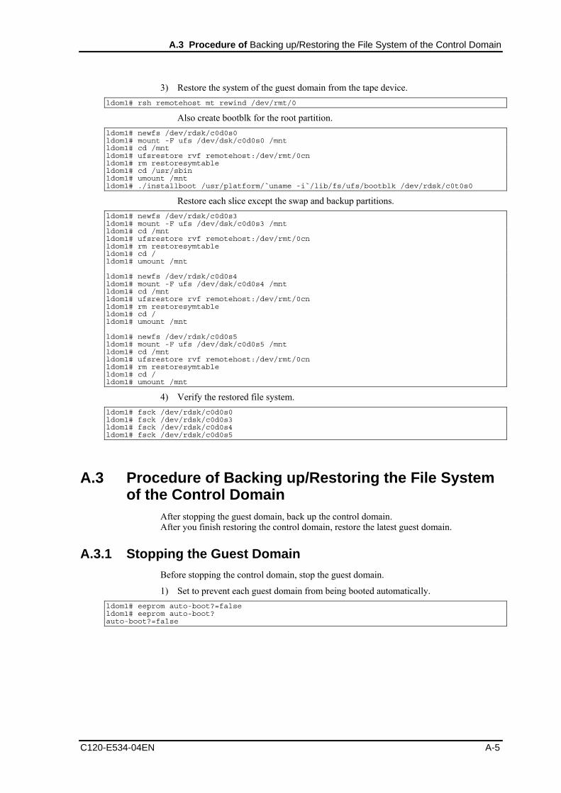
A.3 Procedure of Backing up/Restoring the File System of the Control Domain
3) Restore the system of the guest domain from the tape device. ldom1# rsh remotehost mt rewind /dev/rmt/0
Also create bootblk for the root partition. ldom1# newfs /dev/rdsk/c0d0s0 ldom1# mount -F ufs /dev/dsk/c0d0s0 /mnt ldom1# cd /mnt ldom1# ufsrestore rvf remotehost:/dev/rmt/0cn ldom1# rm restoresymtable ldom1# cd /usr/sbin ldom1# umount /mnt ldom1# ./installboot /usr/platform/`uname -i`/lib/fs/ufs/bootblk /dev/rdsk/c0t0s0
Restore each slice except the swap and backup partitions. ldom1# newfs /dev/rdsk/c0d0s3 ldom1# mount -F ufs /dev/dsk/c0d0s3 /mnt ldom1# cd /mnt ldom1# ufsrestore rvf remotehost:/dev/rmt/0cn ldom1# rm restoresymtable ldom1# cd / ldom1# umount /mnt ldom1# newfs /dev/rdsk/c0d0s4 ldom1# mount -F ufs /dev/dsk/c0d0s4 /mnt ldom1# cd /mnt ldom1# ufsrestore rvf remotehost:/dev/rmt/0cn ldom1# rm restoresymtable ldom1# cd / ldom1# umount /mnt ldom1# newfs /dev/rdsk/c0d0s5 ldom1# mount -F ufs /dev/dsk/c0d0s5 /mnt ldom1# cd /mnt ldom1# ufsrestore rvf remotehost:/dev/rmt/0cn ldom1# rm restoresymtable ldom1# cd / ldom1# umount /mnt
4) Verify the restored file system. ldom1# fsck /dev/rdsk/c0d0s0 ldom1# fsck /dev/rdsk/c0d0s3 ldom1# fsck /dev/rdsk/c0d0s4 ldom1# fsck /dev/rdsk/c0d0s5
A.3 Procedure of Backing up/Restoring the File System of the Control Domain
After stopping the guest domain, back up the control domain. After you finish restoring the control domain, restore the latest guest domain.
A.3.1 Stopping the Guest Domain Before stopping the control domain, stop the guest domain.
1) Set to prevent each guest domain from being booted automatically. ldom1# eeprom auto-boot?=false ldom1# eeprom auto-boot? auto-boot?=false
C120-E534-04EN A-5
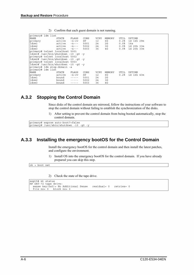
Backup and Restore Procedure
2) Confirm that each guest domain is not running. primary# ldm list NAME STATE FLAGS CONS VCPU MEMORY UTIL UPTIME primary active -n-cv SP 12 6G 0.2% 1d 16h 29m ldom1 active -n--- 5001 24 2G 0.0% 16s ldom2 active -n--- 5002 24 3G 0.0% 1d 20h 33m ldom3 active -n--- 5003 36 4G 0.0% 1d 20h 33m primary# telnet localhost 5001 ldom1# /usr/bin/shutdown -i0 -g0 -y primary# telnet localhost 5002 ldom2# /usr/bin/shutdown -i0 -g0 -y primary# telnet localhost 5003 ldom3# /usr/bin/shutdown -i0 -g0 -y primary# ldm stop-domain -a primary# ldm list NAME STATE FLAGS CONS VCPU MEMORY UTIL UPTIME primary active -n-cv SP 12 6G 0.2% 1d 16h 43m ldom1 bound ----- 5001 24 2G ldom2 bound ----- 5002 24 3G ldom3 bound ----- 5003 36 4G
A.3.2 Stopping the Control Domain Since disks of the control domain are mirrored, follow the instructions of your software to stop the control domain without failing to establish the synchronization of the disks.
1) After setting to prevent the control domain from being booted automatically, stop the control domain.
primary# eeprom auto-boot?=false primary# /usr/sbin/shutdown -i0 -g0 -y
A.3.3 Installing the emergency bootOS for the Control Domain Install the emergency bootOS for the control domain and then install the latest patches, and configure the environment.
1) Install OS into the emergency bootOS for the control domain. If you have already prepared you can skip this step.
ok > boot net
2) Check the state of the tape drive. sept5# mt status HP DAT-72 tape drive: sense key(0x0)= No Additional Sense residual= 0 retries= 0 file no= 0 block no= 0
A-6 C120-E534-04EN

A.3 Procedure of Backing up/Restoring the File System of the Control Domain
A.3.4 Backing up the Control Domain Start from the emergency bootOS for the control domain to back up the control domain.
1) Start from the emergency boot disk for the control domain. {0} ok setenv boot-device disk1 boot-device = disk1
2) Collect vtoc information of the disk to be backed up. sept5# prtvtoc /dev/rdsk/c1t0d0s2 > c1t0d0s2.vtoc
3) Back up the system of the control domain. sept5# mt rewind /dev/rmt/0 sept5# ufsdump 0ucf /dev/rmt/0cn /dev/rdsk/c1t0d0s0 sept5# ufsdump 0ucf /dev/rmt/0cn /dev/rdsk/c1t0d0s3
4) Confirm what you backed up. sept5# mt rewind /dev/rmt/0 sept5# ufsrestore tf /dev/rmt/0cn > ufsrest-tf-c1t0d0s0.log sept5# ufsrestore tf /dev/rmt/0cn > ufsrest-tf-c1t0d0s3.log
A.3.5 Restoring the Control Domain Boot from the emergency bootOS for the control domain to restore the control domain.
1) Format the destination disk of the restoration. sept5# fmthard -s c1t0d0s2.vtoc /dev/rdsk/c1t0d0s2
2) Restore the system of the control domain from the tape device. sept5# rsh remotehost mt rewind /dev/rmt/0
Create bootblk for the root partition. sept5# newfs /dev/rdsk/c1t0d0s0 sept5# mount -F ufs /dev/dsk/c1t0d0s0 /mnt sept5# cd /mnt sept5# ufsrestore rvf remotehost:/dev/rmt/0cn sept5# rm restoresymtable sept5# cd /usr/sbin sept5# umount /mnt sept5# ./installboot /usr/platform/`uname -i`/lib/fs/ufs/bootblk /dev/rdsk/c1t0d0s0
Restore each slice except the swap and backup partitions. sept5# newfs /dev/rdsk/c1t0d0s3 sept5# mount -F ufs /dev/dsk/c1t0d0s3 /mnt sept5# cd /mnt sept5# ufsrestore rvf remotehost:/dev/rmt/0cn sept5# rm restoresymtable sept5# cd / sept5# umount /mnt
3) Verify the restored file system. sept5# fsck /dev/rdsk/c1t0d0s0 sept5# fsck /dev/rdsk/c1t0d0s3
C120-E534-04EN A-7
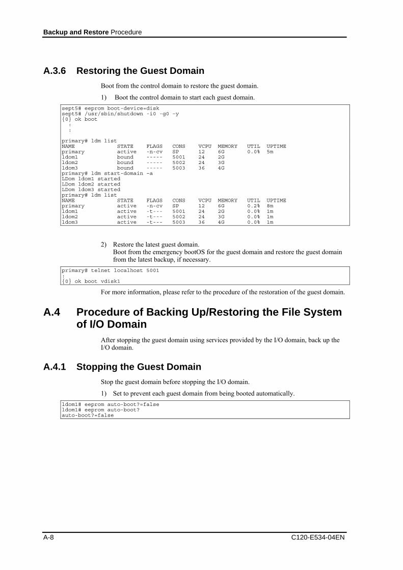
Backup and Restore Procedure
A.3.6 Restoring the Guest Domain Boot from the control domain to restore the guest domain.
1) Boot the control domain to start each guest domain. sept5# eeprom boot-device=disk sept5# /usr/sbin/shutdown -i0 -g0 –y {0} ok boot : : primary# ldm list NAME STATE FLAGS CONS VCPU MEMORY UTIL UPTIME primary active -n-cv SP 12 6G 0.0% 5m ldom1 bound ----- 5001 24 2G ldom2 bound ----- 5002 24 3G ldom3 bound ----- 5003 36 4G primary# ldm start-domain –a LDom ldom1 started LDom ldom2 started LDom ldom3 started primary# ldm list NAME STATE FLAGS CONS VCPU MEMORY UTIL UPTIME primary active -n-cv SP 12 6G 0.2% 8m ldom1 active -t--- 5001 24 2G 0.0% 1m ldom2 active -t--- 5002 24 3G 0.0% 1m ldom3 active -t--- 5003 36 4G 0.0% 1m
2) Restore the latest guest domain. Boot from the emergency bootOS for the guest domain and restore the guest domain from the latest backup, if necessary.
primary# telnet localhost 5001 : {0} ok boot vdisk1
For more information, please refer to the procedure of the restoration of the guest domain.
A.4 Procedure of Backing Up/Restoring the File System of I/O Domain
After stopping the guest domain using services provided by the I/O domain, back up the I/O domain.
A.4.1 Stopping the Guest Domain Stop the guest domain before stopping the I/O domain.
1) Set to prevent each guest domain from being booted automatically. ldom1# eeprom auto-boot?=false ldom1# eeprom auto-boot? auto-boot?=false
A-8 C120-E534-04EN
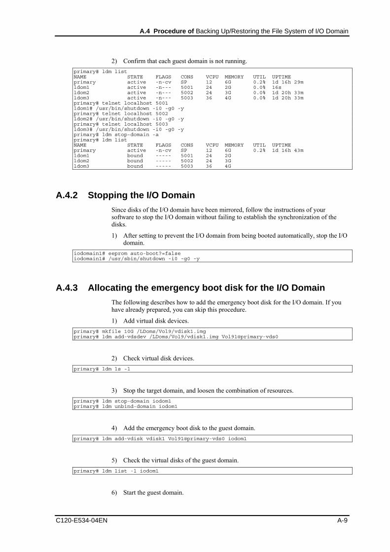
A.4 Procedure of Backing Up/Restoring the File System of I/O Domain
2) Confirm that each guest domain is not running. primary# ldm list NAME STATE FLAGS CONS VCPU MEMORY UTIL UPTIME primary active -n-cv SP 12 6G 0.2% 1d 16h 29m ldom1 active -n--- 5001 24 2G 0.0% 16s ldom2 active -n--- 5002 24 3G 0.0% 1d 20h 33m ldom3 active -n--- 5003 36 4G 0.0% 1d 20h 33m primary# telnet localhost 5001 ldom1# /usr/bin/shutdown -i0 -g0 -y primary# telnet localhost 5002 ldom2# /usr/bin/shutdown -i0 -g0 -y primary# telnet localhost 5003 ldom3# /usr/bin/shutdown -i0 -g0 -y primary# ldm stop-domain -a primary# ldm list NAME STATE FLAGS CONS VCPU MEMORY UTIL UPTIME primary active -n-cv SP 12 6G 0.2% 1d 16h 43m ldom1 bound ----- 5001 24 2G ldom2 bound ----- 5002 24 3G ldom3 bound ----- 5003 36 4G
A.4.2 Stopping the I/O Domain Since disks of the I/O domain have been mirrored, follow the instructions of your software to stop the I/O domain without failing to establish the synchronization of the disks.
1) After setting to prevent the I/O domain from being booted automatically, stop the I/O domain.
iodomain1# eeprom auto-boot?=false iodomain1# /usr/sbin/shutdown -i0 -g0 -y
A.4.3 Allocating the emergency boot disk for the I/O Domain The following describes how to add the emergency boot disk for the I/O domain. If you have already prepared, you can skip this procedure.
1) Add virtual disk devices. primary# mkfile 10G /LDoms/Vol9/vdisk1.img primary# ldm add-vdsdev /LDoms/Vol9/vdisk1.img Vol91@primary-vds0
2) Check virtual disk devices. primary# ldm ls -l
3) Stop the target domain, and loosen the combination of resources. primary# ldm stop-domain iodom1 primary# ldm unbind-domain iodom1
4) Add the emergency boot disk to the guest domain. primary# ldm add-vdisk vdisk1 Vol91@primary-vds0 iodom1
5) Check the virtual disks of the guest domain. primary# ldm list -l iodom1
6) Start the guest domain.
C120-E534-04EN A-9

Backup and Restore Procedure
primary# ldm bind-domain iodom1 primary# ldm start-domain iodom1
7) After logging in to the guest domain, reconfigure devices. iodom1# devfsadm
8) Check the disks of the guest domain. iodom1# format Searching for disks...done AVAILABLE DISK SELECTIONS: 0. c0d0 <SUN-DiskImage-10GB cyl 34950 alt 2 hd 1 sec 600> /virtual-devices@100/channel-devices@200/disk@0 1. c0d1 <SUN-DiskImage-10GB cyl 34950 alt 2 hd 1 sec 600> /virtual-devices@100/channel-devices@200/disk@1 Specify disk (enter its number):
A.4.4 Installing the emergency boot disk for the I/O Domain 1) Install the emergency bootOS for the I/O domain, and then apply the latest patches
and configure the environment. If you have already prepared, you can skip this procedure.
iodom1# /usr/sbin/shutdown -i0 -g0 -y ok > boot vnet0
2) Add the I/O domain entry on the /etc/inet/hosts file or the name service of the remote host (remotehost) to which the tape device is connected. After you finish, return the setting to its original setting in case any security issues occur.
remotehost# echo "xxx.xxx.xxx.xxx iodom1" >> /etc/inet/hosts
3) Add the remote host entry on the /etc/inet/hosts file or the name service of the guest domain.
iodom1# echo "xxx.xxx.xxx.yyy remotehost" >> /etc/inet/hosts
4) Make the rlogin service of the remote host operational. remotehost# cat "iodom1" >> $HOME/.rhosts remotehost# chmod 0400 $HOME/.rhosts
5) Check the state of the remote tape drive. iodom1# rsh remotehost mt status HP DAT-72 tape drive: sense key(0x0)= No Additional Sense residual= 0 retries= 0 file no= 0 block no= 0
A-10 C120-E534-04EN

A.4 Procedure of Backing Up/Restoring the File System of I/O Domain
A.4.5 Backing Up the Guest Domain Boot from the emergency bootOS of domains to back up the guest domain.
1) Boot from the emergency boot disk for the I/O domain. primary# telnet localhost 5009 : {0} ok boot vdisk1
2) Collect vtoc information of disks to be backed up. iodom1# prtvtoc /dev/rdsk/c0d0s2 > iodom1-disk0.vtoc
3) Back up the system of the I/O domain. iodom1# rsh remotehost mt rewind /dev/rmt/0 iodom1# ufsdump 0ucf remotehost:/dev/rmt/0cn /dev/rdsk/c0d0s0 iodom1# ufsdump 0ucf remotehost:/dev/rmt/0cn /dev/rdsk/c0d0s3 iodom1# ufsdump 0ucf remotehost:/dev/rmt/0cn /dev/rdsk/c0d0s4 iodom1# ufsdump 0ucf remotehost:/dev/rmt/0cn /dev/rdsk/c0d0s5
4) Check what you backed up. iodom1# rsh remotehost mt rewind /dev/rmt/0 iodom1# ufsrestore tf remotehost:/dev/rmt/0cn > ufsrest-tf-c0d0s0.log iodom1# ufsrestore tf remotehost:/dev/rmt/0cn > ufsrest-tf-c0d0s3.log iodom1# ufsrestore tf remotehost:/dev/rmt/0cn > ufsrest-tf-c0d0s4.log iodom1# ufsrestore tf remotehost:/dev/rmt/0cn > ufsrest-tf-c0d0s5.log
C120-E534-04EN A-11
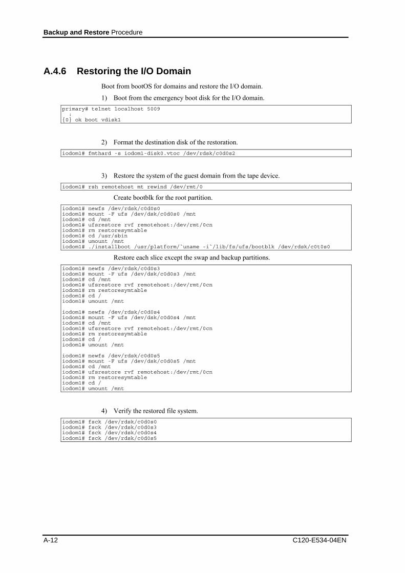
Backup and Restore Procedure
A-12 C120-E534-04EN
A.4.6 Restoring the I/O Domain Boot from bootOS for domains and restore the I/O domain.
1) Boot from the emergency boot disk for the I/O domain. primary# telnet localhost 5009 : {0} ok boot vdisk1
2) Format the destination disk of the restoration. iodom1# fmthard -s iodom1-disk0.vtoc /dev/rdsk/c0d0s2
3) Restore the system of the guest domain from the tape device. iodom1# rsh remotehost mt rewind /dev/rmt/0
Create bootblk for the root partition. iodom1# newfs /dev/rdsk/c0d0s0 iodom1# mount -F ufs /dev/dsk/c0d0s0 /mnt iodom1# cd /mnt iodom1# ufsrestore rvf remotehost:/dev/rmt/0cn iodom1# rm restoresymtable iodom1# cd /usr/sbin iodom1# umount /mnt iodom1# ./installboot /usr/platform/`uname -i`/lib/fs/ufs/bootblk /dev/rdsk/c0t0s0
Restore each slice except the swap and backup partitions. iodom1# newfs /dev/rdsk/c0d0s3 iodom1# mount -F ufs /dev/dsk/c0d0s3 /mnt iodom1# cd /mnt iodom1# ufsrestore rvf remotehost:/dev/rmt/0cn iodom1# rm restoresymtable iodom1# cd / iodom1# umount /mnt iodom1# newfs /dev/rdsk/c0d0s4 iodom1# mount -F ufs /dev/dsk/c0d0s4 /mnt iodom1# cd /mnt iodom1# ufsrestore rvf remotehost:/dev/rmt/0cn iodom1# rm restoresymtable iodom1# cd / iodom1# umount /mnt iodom1# newfs /dev/rdsk/c0d0s5 iodom1# mount -F ufs /dev/dsk/c0d0s5 /mnt iodom1# cd /mnt iodom1# ufsrestore rvf remotehost:/dev/rmt/0cn iodom1# rm restoresymtable iodom1# cd / iodom1# umount /mnt
4) Verify the restored file system. iodom1# fsck /dev/rdsk/c0d0s0 iodom1# fsck /dev/rdsk/c0d0s3 iodom1# fsck /dev/rdsk/c0d0s4 iodom1# fsck /dev/rdsk/c0d0s5

C120-E534-04EN B-1
Appendix B Supplement
This supplement explains the relations between an internal disk, an I/O slot, on-board LAN and a logical domain, when using LDoms.
• The following shows configurations when all I/Os are connected to the control domain and when I/Os are divided into the control domain and the guest domain (also used as I/O domain).
SPARC Enterprise T5140
Note: In the second configuration example, XAUI card is not implemented. A LAN card needs to be added to the control domain.
Configuration Pattern 2
Control Domain
Internal
Disk
DVD-ROM
PCI Slot 2
PCI Slot 1
PCI Slot 0
Onboard LAN(4ports)
Guest Domain
Guest Domain
Guest Domain
Configuration Pattern 1
Control Domain
Internal
Disk
PCI Slot 2
PCI Slot 1
Guest Domain (Also I/O Domain)
PCI Slot 0
Onboard LAN(4ports)
Guest Domain
Guest Domain
DVD-ROM

Supplement
B-2 C120-E534-04EN
SPARC Enterprise T5240
Note: In the second configuration example, XAUI card is not implemented. A LAN card needs to be added to the control domain.
Configuration Pattern 2
Guest Domain
Control Domain
Internal
Disk
PCI slot 3
PCI slot 2
PCI slot 1
Guest Domain (Also I/O Domain)
Onboard LAN(4ports)
PCI slot 5
PCI slot 4
PCI slot 0
Guest Domain
DVD-ROM
Guest Domain
Guest Domain
Guest Domain
DVD-ROM
Control Domain
Internal
Disk
Onboard LAN (4ports)
PCI slot 2
PCI slot 1
PCI slot 0
PCI slot 5
PCI slot 4
PCI slot 3
DVD-ROM
Configuration Pattern 1

Supplement
C120-E534-04EN B-3
SPARC Enterprise T5440
Note: In the second configuration example, XAUI card is not implemented. A LAN card needs to be added to the control domain.
Guest Domain
Guest Domain
Guest Domain
DVD-ROM
Control Domain
Internal
Disk
Onboard LAN (4ports)
PCI slot 2
PCI slot 1
PCI slot 0
PCI slot 5
PCI slot 4
PCI slot 3
DVD-ROM
Configuration Pattern 1
PCI slot 6
PCI slot 7
Configuration Pattern 2
Guest Domain
Control Domain
Internal
Disk
PCI slot 4
PCI slot 1
PCI slot 0
Guest Domain (Also I/O Domain)
Onboard LAN (4ports)
PCI slot 6
PCI slot 3
PCI slot 2
Guest Domain
DVD-ROM
PCI slot 5 PCI slot 7

Supplement
Configuration Pattern 3
B-4 C120-E534-04EN
Note: In the second configuration example, XAUI card is not implemented. A LAN card needs to be added to the control domain.
Guest Domain (Also I/O Domain)
Guest Domain (Also I/O Domain)
PCI slot 6
PCI slot 7
Guest Domain
Control Domain
DVD-ROM
Internal
Disk
PCI slot 4
PCI slot 2
PCI slot 3
PCI slot 0
PCI slot 1
PCI slot 5
Onboard LAN (4ports)

C120-E534-04EN C-1
Appendix C Instructions for Backup/Restoration of ZFS file system
Here backup/restoration of ZFS file system is described.
LDoms 1.1 or later supports ZFS file system.
On each guest domain, perform backup/restoration of a file system of a guest domain only for virtual disks combined with the domain.
Please refer to the following manuals regarding backup/restoration of the file system.
System Administration Guide (Devices and File Systems) http://docs.sun.com/app/docs/doc/817-5093
Solaris ZFS Administration Guide http://docs.sun.com/app/docs/doc/819-5461
You can install system volume on ZFS file system on Solaris OS 10/08 or later. The following describes examples of backup/restoration procedure of ZFS file system.
ex)Notes on the procedure * In the example, UFS file system on a disk device is used as the backup
destination. * Restore the environment in order to avoid a security issue when you use
remote a tape drive. * About disks to be used c0t2d0s0 :Disk where the control domain is stored. c0t1d0 :Disk where the guest domain is stored. c0t3d0s7 :Disk where backup is stored.
C.1 Backup of ZFS file system 1) Preparation
Collect information by zpool, disk, and filesystems beforehand, and backup it into another disk. A record of information collected with ‘get all’ should be kept because the record is useful for check after you restore the file system.
The following is an example of log images stored into logfile_get_all_org.txt.
primary# script logfile_get_all_org.txt
primary# zpool list
NAME SIZE USED AVAIL CAP HEALTH ALTROOT
ldomspool 68G 10.0G 58.0G 14% ONLINE -
rpool 48.8G 16.9G 31.8G 34% ONLINE -
primary# zfs list
NAME USED AVAIL REFER MOUNTPOINT
ldomspool 10.0G 56.9G 19K /ldomspool
ldomspool/ldom2 10.0G 56.9G 10.0G
/ldomspool/ldom2
rpool 18.9G 29.1G 93K /rpool
rpool/ROOT 15.9G 29.1G 18K legacy
rpool/ROOT/s10s_u6wos_07b 15.9G 29.1G 15.9G /
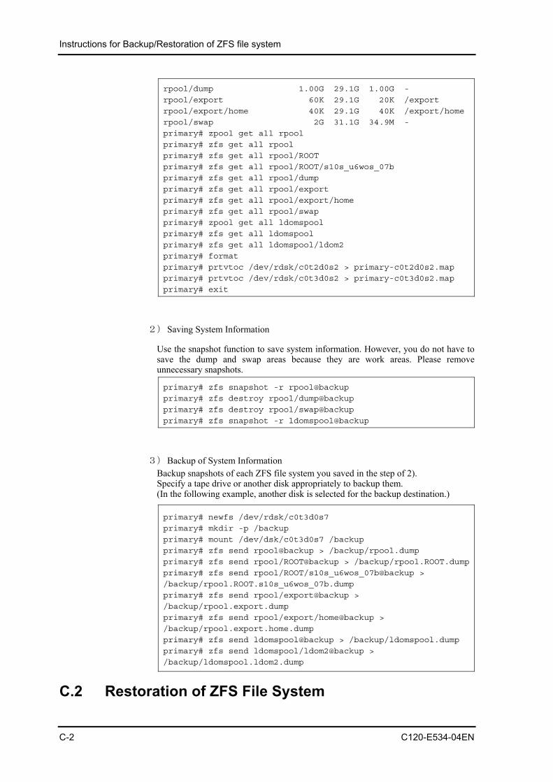
Instructions for Backup/Restoration of ZFS file system
C-2 C120-E534-04EN
rpool/dump 1.00G 29.1G 1.00G -
rpool/export 60K 29.1G 20K /export
rpool/export/home 40K 29.1G 40K /export/home
rpool/swap 2G 31.1G 34.9M -
primary# zpool get all rpool
primary# zfs get all rpool
primary# zfs get all rpool/ROOT
primary# zfs get all rpool/ROOT/s10s_u6wos_07b
primary# zfs get all rpool/dump
primary# zfs get all rpool/export
primary# zfs get all rpool/export/home
primary# zfs get all rpool/swap
primary# zpool get all ldomspool
primary# zfs get all ldomspool
primary# zfs get all ldomspool/ldom2
primary# format
primary# prtvtoc /dev/rdsk/c0t2d0s2 > primary-c0t2d0s2.map
primary# prtvtoc /dev/rdsk/c0t3d0s2 > primary-c0t3d0s2.map
primary# exit
2) Saving System Information
Use the snapshot function to save system information. However, you do not have to save the dump and swap areas because they are work areas. Please remove unnecessary snapshots.
primary# zfs snapshot -r rpool@backup
primary# zfs destroy rpool/dump@backup
primary# zfs destroy rpool/swap@backup
primary# zfs snapshot -r ldomspool@backup
3) Backup of System Information Backup snapshots of each ZFS file system you saved in the step of 2). Specify a tape drive or another disk appropriately to backup them. (In the following example, another disk is selected for the backup destination.)
primary# newfs /dev/rdsk/c0t3d0s7
primary# mkdir -p /backup
primary# mount /dev/dsk/c0t3d0s7 /backup
primary# zfs send rpool@backup > /backup/rpool.dump
primary# zfs send rpool/ROOT@backup > /backup/rpool.ROOT.dump
primary# zfs send rpool/ROOT/s10s_u6wos_07b@backup >
/backup/rpool.ROOT.s10s_u6wos_07b.dump
primary# zfs send rpool/export@backup >
/backup/rpool.export.dump
primary# zfs send rpool/export/home@backup >
/backup/rpool.export.home.dump
primary# zfs send ldomspool@backup > /backup/ldomspool.dump
primary# zfs send ldomspool/ldom2@backup >
/backup/ldomspool.ldom2.dump
C.2 Restoration of ZFS File System

Instructions for Backup/Restoration of ZFS file system
1) Preparation of Restoration Destination System
(1) Boot the system in single use mode from a network installation environment. ※You need to configure the network installation environment beforehand.
{0} ok boot net -s
(2) Create disk slice and disk label by using the format(1M) or fmthard(1M) command according to disk partition information you recorded beforehand.
# format
or
# fmthard –s primary-c0t2d0s2.map /dev/rdsk/c0t2d0s2
# fmthard –s primary-c0t3d0s2.map /dev/rdsk/c0t3d0s2
2) Restoration of System File
Restore the system information you backuped from external media such as a tape drive.
(1) Create a new storage pool to mount the disk where backuped files are stored.
# zpool create -fo altroot=/var/tmp/rpool rpool c0t2d0s0
# mount /dev/dsk/c0t3d0s7 /mnt
(2) Restore disks composing ‘rpool’.
# zfs receive -Fd rpool < /mnt/rpool.dump
# zfs receive -Fd rpool < /mnt/rpool.ROOT.dump
# zfs receive -Fd rpool < /mnt/rpool.ROOT.s10s_u6wos_07b.dump
# zfs receive -Fd rpool < /mnt/rpool.export.dump
# zfs receive -Fd rpool < /mnt/rpool.export.home.dump
(3) Create ‘dump’ and ‘swap’.
You need to create ‘dump’ and ‘swap’ individually because they are not backuped.
Information of ‘dump’ and ‘swap’ collected in the step 1) of C.1.
primary# zfs get all rpool/dump
NAME PROPERTY VALUE SOURCE
rpool/dump type volume -
rpool/dump creation Tue Apr 7 18:13 2009 -
rpool/dump used 1.00G -
rpool/dump available 29.1G -
rpool/dump referenced 1.00G -
rpool/dump compressratio 1.00x -
rpool/dump reservation none default
rpool/dump volsize 1G -
rpool/dump volblocksize 128K -
C120-E534-04EN C-3

Instructions for Backup/Restoration of ZFS file system
rpool/dump checksum off local
rpool/dump compression off local
rpool/dump readonly off default
rpool/dump shareiscsi off default
rpool/dump copies 1 default
rpool/dump refreservation none default
primary# zfs get all rpool/swap
NAME PROPERTY VALUE SOURCE
rpool/swap type volume -
rpool/swap creation Tue Apr 7 18:13 2009 -
rpool/swap used 2G -
rpool/swap available 31.1G -
rpool/swap referenced 34.9M -
rpool/swap compressratio 1.00x -
rpool/swap reservation none default
rpool/swap volsize 2G -
rpool/swap volblocksize 8K -
rpool/swap checksum on default
rpool/swap compression off default
rpool/swap readonly off default
rpool/swap shareiscsi off default
rpool/swap copies 1 default
rpool/swap refreservation 2G local
primary#
Specify ‘volsize’ for the –V option of the ‘create’.
# zfs create -V 1g rpool/dump
# zfs create -V 2g rpool/swap
3) Create ‘bootblock’.
# installboot -F zfs /usr/platform/`uname
-i`/lib/fs/zfs/bootblk /dev/rdsk/c0t2d0s0
# zpool set bootfs=rpool/ROOT/s10s_u6wos_07b rpool
# zfs set canmount=noauto rpool/ROOT/s10s_u6wos_07b
# zfs set mountpoint=/ rpool/ROOT/s10s_u6wos_07b
# zfs set mountpoint=/rpool rpool
4) Boot the system from rpool.
# shutdown –g0 –i0 –y
{1} ok boot
5) Check after Restoration Collect the same information that you collected in the preparation for system backup (C1. 1)) and check whether there are any errors in it. The following example shows log images stored in logfile_get_all_new.txt. primary# script logfile_get_all_new.txt
C-4 C120-E534-04EN

Instructions for Backup/Restoration of ZFS file system
C120-E534-04EN C-5
primary# zpool get all rpool
primary# zfs get all rpool
primary# zfs get all rpool/ROOT
primary# zfs get all rpool/ROOT/s10s_u6wos_07b
primary# zfs get all rpool/dump
primary# zfs get all rpool/export
primary# zfs get all rpool/export/home
primary# zfs get all rpool/swap
primary# zpool get all ldomspool
primary# zfs get all ldomspool
primary# zfs get all ldomspool/ldom2
primary# exit