
Space Station Automation and - ntrs.nasa.gov IS the final report of a Space Station Automation and...
73
November 1984 NASA-CR-176095 19850024859 Final Concept Definition and Technology Assessment 0483-10027-1 Space Station Automation and Robotics Study Operator-Systems Interface NO\! 6 1985 U,l, ( 1111111111111 1111 11111 11111 1111111111 1111 1111 NF01763 https://ntrs.nasa.gov/search.jsp?R=19850024859 2018-05-23T07:59:36+00:00Z
Transcript of Space Station Automation and - ntrs.nasa.gov IS the final report of a Space Station Automation and...
November 1984
NASA-CR-176095 19850024859
Final Rep~rt Concept Definition and Technology Assessment 0483-10027-1
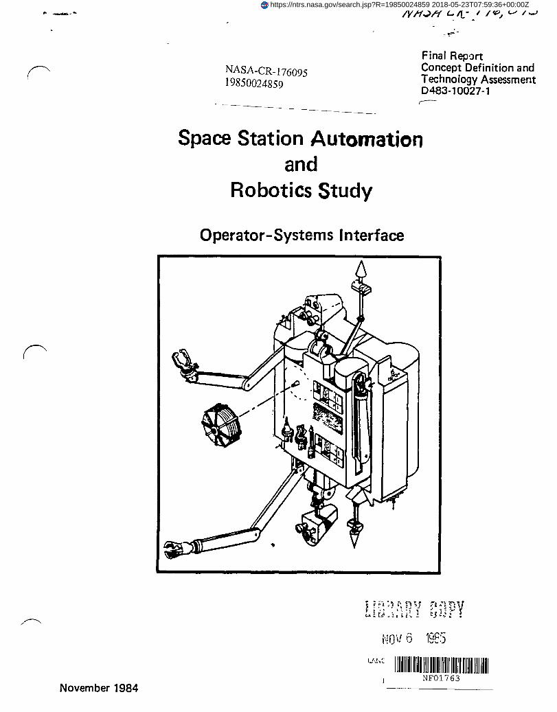
Space Station Automation and
Robotics Study
Operator-Systems Interface
NO\! 6 1985
U,l, ( 1111111111111 1111 11111 11111 1111111111 1111 1111 NF01763
https://ntrs.nasa.gov/search.jsp?R=19850024859 2018-05-23T07:59:36+00:00Z

..
D48310027-1
Space Station Automation and Robotics Study
Final Report
Operator - Systems Interface
Conducted for NASA
November 1984
Boeing Aerospace Company and
Boeing Computer Services Company

D483-10027-1
Foreword
In May of 1984, NASA initiated an Automation and Robotics Technology Planning Study In
response to a mandate from the U S. Congress associated with appropnatlons for the
Space Station.
Boeing Aerospace Company initiated this study ofthe Operator-System Interface (OSI) In
August of 1984 In response to a need expressed by NASA for study coverage In that area
The study:
• Charactenzes an OSI for an extra vehicular (EV) robot system to perform
maintenance functions on the Space Station,
• Develops OSI senanos for that system, and
• Assesses the associated technologies
Dr Victor Anselmo was the NASA manager of the study and the Boeing effort was lead by
Paul Meyer of Boeing Aerospace Company, who was supported by Dr. Douglas Dorrough
and Ron Hammond of the Boeing Computer Services Artificial Intelligence Center. Other
contnbuters to this report are Joe Hopkins, Henry Lahore, Mark Lawler, Judi Qualy
White, and Amy Toussaint.
KeyWords
Space Station
Operator-Systems Interface
EV Robot
Artificial Intelligence
Autonomous
Pagel

D483-10027-1
TABLE OF CONTENTS
Foreword
Table of Contents
List of Figures IV
V List of Tables
List of Abbreviations
1.0
20
r----- 3.0
INTRODUCTION
1.1 Scope of Study
1.2 Definitions
1.3 Organization of this Report
STUDY OVERVIEW
DESCRIPTION OF THE OSI FOR AN EV ROBOT
3.1 Critical and Routme Tasks
3.2 Scenarios
3.2.1 Full Day Scenario
3.2.2 Operator/System Dialogue
3.3 Operator-Systems Interface
3.3.1 Communication Functions
3.3 1 1
3.3.1 2
3.3.1.3
Displays
VOice Recognition and SynthesIs
Data Display and Exchange
3.3.2 Robot Task Planning and Scheduling
3.3 3 Anomaly Management
Page Ii
Ii
VI
1-1
1-4
1-7
1-8
2-1
3-1
3-1
3-2
3-3
3-6
3-9
3-9
3-9
3-10
3-11
3-12
3-13

D483-1 0027-1
4.0 TECHNOLOGY ASSESSMENT 4-1
4.1 Technology Assessment· Project TAARGET 4-1
4.1.1 Factors Influencmg Technology Development -- Push and Pull 4-2
4.1.2 Project TAARGET 4-3
4.2 Summary of the OSI Technology Assessment 4-9
4.2.1 Phase 1: Human Directed 4-11
42.2 Phase 2 Human Monitored 4-15
4.2.3 Phase 3 Human Instruction and Cnsls Intervention 4-16
43 Phased OSI Technology Push 4-18
4.3 1 Phase 1 Push 4-19
4.3 2 Phase 2 Push 4-21
4.3 3 Phase 3 Push 4-23
4.4 Alternative Paths to Robotic Autonomy 4-26
5.0 CONCLUSIONS AND RECOMMENDATIONS 5-1
6.0 REFERENCES AND BIBLIOGRAPHY 6-1
Page III

0483-10027-1
LIST OF FIGURES
1-1 Work Breakdown Structure 1-2
1-2 AI Center Functional Organization 1-3
1-3 Area of Focus 1-5
1-4 Software Aspects of 051 for Robot Control 1-6
2-1 Space Station Aspects of 051 2-4
2-2 An External Robot Concept 2-6
2-3 EV RobotTask Flow 2-7
4-1 DIRECT: Main Program 4-5
4-2a Interrelation of Risk Parameters 4-6
4-2b TYPical DIRECT Output 4-7
~ 4-3 Future Speech Recognition 4-13 I
4-4 RCPL Specification of Technology Push for 051 Phase 1 4-14
4-5 051 Phase 1 Technology Push 4-20
4-6 051 Phase 2 Technology Push 4-22
4-7 051 Phase 3 Technology Push for Learning Systems 4-24
4-8 051 Phase 3 Technology Push 4-25
Page iv

D483-10027-1
LIST OF TABLES
4-1 Partial Outputs From DIRECT 4-6
4-2 Demonstration Types and Characteristics 4-8
4-3 Scenario-Derived 051 Operational Requirements (Stressing Scenario) 4-9
4-4a Generic Evolution of Autonomy 4-10
4-4b Degrees of 051 4-10
4-5 Metrics for 051 Phase 1 Technology Push 4-21
4-6 Metrics for 051 Phase 2 Technology Push 4-23
4-7 Metrics for 051 Phase 3 Technology Push 4-26
4-8 Oplnionator Response to Feasibility of Autonomous Robots Evolving
from Teleoperatlon 4-29
Pagev

D48310027-1
LIST OF ACRONYMS
KBS Knowledge Based System
AI Artlflclallntelhgence MRMS Mobile Remote
A&R Automation and Robotics Manipulator System
BCS Boemg Computer Services MTBF Mean Time Before Failure
CAD Computer Aided Design NASA National Aeronautics and
CAMS CybernetiC Space Admmistratlon
Anthropomorphic OMV Orbltmg Maneuvering
Machme Systems Vehicle
CMG Control Moment Gyros OSI Operator System Interface
DARPA Defense Advanced RCS Reaction Control System
Research Projects RTSR Real Time Systems
Admmlstratlon Research
DIRECT DecIsion Inpact Risk SRI Standford Research r' Evaluation and Control Institute
Technique SIS Sa fety ISa n Ity
DMS Data Management TA Technology Assessment
Systems TAARGET Transnational Assessment
EV Extra Vehicular of Autonomous RobotiC
EVA Extra Vehicular Activity Generational and
FOV field of view EvolutlonaryTechnology
GTR GenencTechnology TV TelevIsion
ReqUirements TVKC TeleVISion Augmented
HUD Head Up Display Khatib Control
IBM International Busmess VHSIC Very High Speed
Machmes Integrated CirCUit
IC Integrated CirCUit VICE VOice Intentionally
IOC Initial Operational Constramed Evaluator
Capablhty VLSIC Very Large Scale
IV Inter Vehicular Integrated CIrCUit
KBIU Knowledge Based Image ~ Understandmg (
Page VI

D483-10027-1
1.0 INTRODUCTION
This IS the final report of a Space Station Automation and Robotics Planning Study, which
was a JOint project of the Boeing Aerospace Company, Boeing Commercial Airplane
Company, and Boeing Computer Services Company. Figure 1-1 shows the work
breakdown for the Boeing study tasks. This study IS in support of the Advanced
Technology Advisory Committee established by NASA In accordance with a mandate by
the U S Congress. Our support complements that provided to the NASA-Contractor study
team by four aerospace contractors, the Stanford Research Institute (SRI), and the
California Space Institute. This study Identifies automation and robotics (A&R)
technologies that can be advanced by requirements levied by the Space Station program.
The methodology used In the study IS to establish functional requirements for the
operator-system-Interface (OSI), establish the technologies needed to meet these
requirements, and to forecast the availability ofthese technologies
Boeing entered the study In the third month of a SIX month effort to address the OSllssues
f" (sometimes called man-machine Interface Issues) The other aerospace companies
working on thiS study focused on functional aspects of automation and robotics including
subsystem management, space manufacturing, free-flyer servIcing and space construction,
but none of the contractors were specifically tasked to address the OSI The OSI IS Integral
to the other tOPICS and affects Space Station technology growth considerations as human
Involvement In Space Station caretaking IS replaced by automation and robots The OSI
tOPIC chosen for thiS study IS not controls and displays, which are relatively well
understood, but rather the advanced automation functions that define these Interfaces.
The roll of SRI In the NASA-Contractor group was to provide focused technology forecasts
to support the analysIs and to gUide the system concept design performed by the
aerospace contractors. Because contracted tasks were set before Boeing JOined the study,
the technology support provided by SRI was not available for our part of the study. The
Boeing Computer Services (BCS) Artificial Intelligence (AI) Center provided similar support
for the 051 tOPICS we addressed. The BCS AI Center IS particularly well sUited to perform
the required technology definition and forecasting tasks because of their connection With
studies on similar tOPICS that have been done for other users Figure 1-2 shows a
r', functional organization chart for the BCS AI Center.
1-1

Boeing Computer Services
(Artificial Intelligence Center)
D48310027-1
Boeing Aerospace Company
(Space Station A&R task force)
• Operator/software interfaces • Management
• Reports Speech/Natural Language
Voice recognition systems
Voice synthesis systems
Use of AI
• Expert systems
• Machine learning
Related AI Technologies
• Technology forecasting
Availability
Holes
Required attention
• Time frame
• Budget
• Station keeping OSI concepts
L ProximIty operations
• External robot
• Robot 051
• concept deScription
• Scenarios
• System parameters
• Skylab astronaut experience
Leonsultallon on human SIde
of 051
Boeing Commercial Airplane
Company
• Consultation
Flight deck designer
experience
• Stationkeeping
requirements
• Interactive controls
and displays
Test pilot experience
• Human side of 7671757
• 051
Figure 1-1: Work Breakdown Structure
1 2
) ) )

')
r-----I I
BCS Commercial
Liaison
-----
Interactive Systems
Research
• KBS Tools Dev.
• Knowledge Based
Systems
• Natural Language
• Software
Engineering
Application
• KBS Support to RTSR
• Intelligence
Management
Center
• Remote Principals
) 048310027-1
Artificial Intelligence Support Center
Real Time Systems
Research
• Sensing
• Robotics
• Speech
Understanding
• Image FacIlity
• Robotics FacIlity
• VOice FacIlity
Technology Transfer
• Technology Transfer
• Associate Program
• CUrriculum
Development
• High-Speed
Computation
• Conferences
• Boeing Education
Program
• Colloquia
• University Relations
• Remote Associates
• External Associates
Figure 1-2 AI CENTER FUNCTIONAL ORGANIZATION
1-3
A. I. Systems
Technology
• Center Technology
• Systems
Programming
• FacIlity Support
• Remote Operations
and Technology
)

D483 10027-1
1.1 Scope of Study
The overall OSI for the Space Station covers operator Interfaces to a wide range of
automation and robotics functions, including subsystem management, planning, mission
management, maintenance m,anagement, logistics management, free-flyer servIcing and
operation, and proximity operations. Each of these Involves the display of mOnitoring,
diagnostic, and advisory information to the crew and the acceptance of planning or
discrete command Inputs from the crew The software functions required to generate,
Interpret, and manage the information, as well as to perform the deciSion making needed
for diagnostic and advisory outputs, will lead to technology advancements The system
characteristics and senarlos that desCribe those software functions constitute the concept
definition output of our study. The technology Identifications and forecasts related to
those functions are the outputs of our study which support technology planning.
Study schedule and resource limitations required us to focus on a speCifiC aspect of OSI.
We selected a tOPIC that drives out advanced software technologies but IS credible for
Space Station use within 10 to 15 years after the initial operational capability (IDC). As
shown In Figure 1-3, our study looked at progressively more detailed Space Station
functions, starting from general station keeping functions, down to proximity operations,
and finally to the extra vehicular (EV) robot functions. The EV robot we envIsion would be
a free-flyer while In transit from one location to another In close proximity to the orbiting
Space Station The OSI would perform path planning, tracking and control, object
recognition, fault detection and correction, and plan modifications In connection with EV
robot operations. The Implementation of the OSI Implies the use of natural languages,
vOice recognition and syntheSIS, speech understanding, expert diagnostic and adVisory
knowledge systems, and machine learning The technologies for these Implementations
are expected to evolve through three distinct phases, as discussed In Section 4 Figure 1-4
shows a flow diagram indicating how software development could support OSI for an E\
robot
1-4

'" ) 048310027-1
SPACE STATION FUNCTIONS
STATIONKEEPING FUNCTIONS
PROXIMITY OPERATIONS
" " \ \ \ \ \ \ \ \ \ \ \ \ \ \ \ \ \
" " "
EXTRA VEHICULAR ROBOT
..
\ .,. ...... -Figure 1·) AREA OF FOCUS
)

PROBLEM SEQUENCE SAFETY ,~
SOLVING OF GOALS I- ' MONITOR (INDEPENDENT)
I
MOTION -'" ..... - CONCEPT KNOWLEDGE OF CURRENT PLANNING
UNDERSTANDING I-- SYSTEM STATE (RESOURCES. EXPERTS LIMITATIONS. TOOLS, etc) - l I'
TASK -r "" EXECUTION r EXPERTS
NATUAL DYNAMIC
LANGUAGE f-SCENE
UNDERSTANDING SIMULATION INTELLIGENT
'I'
" ./...1 CONTROL
IMAGE (REAL TIME OR PREDICTIVE)
SENSORS/ ...... SPATIAL VOICE VOICE ACTUATORS
INPUT RECOGNITION RESPONSE l l I
ROBOT POINT COMMANDS QUESTIONS FROM SYSTEM. ACTIONS GUIDE RESPONSE TO SUPERVISOR
QUESTIONS. DECISION RATIONALE AND STATUS
• OBJECT , RECOGNITION
HUMAN SUPERVISOR --- • SCENE ANALYSIS
(LEVEL OF DETAIL SPECIFIED BY SUPERVISOR DECREASES AS • PATTERN SYSTEM LEARNS BY EXAMPLES/EXPERIENCE) RECOGNITION
Figure 1-4 SOFTWARE ASPECTS OF OSI FOR ROBOT CONTROL
'·6
) ) )

D48310027-1
~ 1.2 DEFINITIONS
The followmg established defmltlons have been used m this report and are mcluded here
for easy reference.
Automation
Automation IS the use of machmes to effect control of system/subsystem processes m a
predefmed or modelled set of circumstances
Artificial Intelligence
AI is the part of computer sCience concerned with the design and Implementation of
programs that make complicated decIsions, learn or become more adept at making
decIsions, Interact With humans In a way natural to humans, and In general exhibit the
charactenstlcs we associate With mtelilgent human behavior Intelligence, as used here, IS
the ability to meet and cope With novel situations by adJustmg behavior, the ability to
r--" comprehend the interrelationships between facts and concepts, and the ability to
generate new concepts and relationships from those already known, I e., already In a
database ArtifiCial, as used here, mdlcates that mteiligence IS achieved by means of a
computer or electro-mechanlcal-optlcal deVice.
Autonomy
Autonomy is an attnbute of a system/subsystem that will allow It to operate wlthm ItS
specified performance requirements as an mdependent unit or element Without external
mterventlon for a specific penod oftlme.
Expert System
Expert or knowledge based systems are systems that use a significant amount of expert
mformatlon about a particular domain to solve problems m that domam. The system IS
able to perform at the level of a human expert In that domam of knowledge.
1-7

D48310027-1
Knowledge Engineering
This discipline Involves wlh extracting, articulating, and computerizing knowledge.
Knowledge engmeenng addresses the problem of bulldmg skilled computer systems by
extractmg the expert's knowledge and then organlzmg It m an effective Implementation.
Machine Autonomy
Machme autonomy IS defmed as the ability to function as an mdependent unit over an
extended penod of time, while performmg a vanety of actions and while respondmg to
stimuli produced by mtegrally contamed sensors
Robot
A generic term, connotmg many of the following Ideas A machine capable of
manlpulatmg objects and/or movement havmg enough mternal control, sensmg and
computer analysIs to carry out a more or less sophisticated task. The term usually connotes
a certam degree of autonomy and an ability to react appropriately to changmg conditions ~
m ItS environment
Teleoperation
A teleoperated robotic system IS one that utilizes cybernetic anthropomorphic machme
systems (CAMS) technology m order to permit the human operator to transmit his or her
intelligence and dextenty through the machme and to the task All decIsion-making
capability reSides with the human controller A servo-control system usually transmits a
small proportion of the load force to the operator's hand(s), thus glvmg him or her
"mstmctlve control" of the Job. Frequently, SIX degrees of freedom are present These
mclude hOrizontal extenSion, hOiSt, aZimuth rotation, yaw, pitch, and roll.
1.3 Organization of this Report
This report presents an overview of the study, describes an OSI concept for EV robot
operations based on a hypothetical task scenario and astronaut/system interactive
dlalogueue, makes a technology forecast, and sets forth conclUSions and
recommendations.
1-8

~ (
D48310027-1
STUDY OVERVIEW
During the second session of the 98th Congress, the appropriations for Space Station
funding were established by a House/Senate conference In their report, the Senators and
Representatives on that committee emphasized automation and robotics as part of the
Space Station Program, as the following quote from that report Illustrates'
The Space Station Program offers an opportunity to stimulate
the development of advanced technologies In the fields of
automation and robotics. To this end, the conferees adopted
the Senate provIsion establishing an Advanced Technology
Advisory Committee mandated to Identify specific Space Station
systems which advance those technologies that are not In use In
eXisting spacecraft. Examples of such technologies Include
advanced vision sensors, computers that can serve as expert
systems, and manipulator systems with advanced multiple
degrees of freedom. The conferees Intend that, where
appropriate, the Committee may as a secondary task also
Identify systems currently In use whose potential for enhancing
automation and robotics technologies appears promising The
conferees both Intend and expect that the technologies of Space
Station automation and robotics will be Identified and
developed not only to Increase the efficiency of the station Itself
but also to enhance the Nation's technical and sCientific base
leading to more productive industries here on earth.
In response to this directive, NASA established an Aerospace Contractor Study Group to
cover four speCific areas of automation and robotics application to the Space Station.
Satellite ServIcing
Space Manufacturing
Space Assembly and Construction -
Subsystems Management
TRW
General Electric
Martin Marietta
Hughes
Initially Boeing was not a partiCipant, but offered to assist the NASA effort by studYing
the Impact of the operator-systems Interface on Space Station automation. Boeing has
2-1

D48310027-1
significant expenence In that area as part of the advanced commercial airliner flight deck ~ development. The following IS a list of some significant features of the OSI approach to
757/767 flight deck design
• Integrated digital instrumentation
• Flight deck commonality
• Simplified procedures
• Increased automation/decreased workload
• Consistent caution/warning philosophy
• Optimized crew size and accommodations
• Advanced human englneenng deSign methodology
ExtenSive pilot and customer participation
Work load assessment
ExtenSive englneenng Simulation
• QUiet, dark cockpit
OSI IS the system of hardware and software that faCilitates communication between
human operators and the hardware/software system that monitors and controls a ~
functional system On the Space Station, the functional systems that will be controlled and
mOnitored will Include those Involved with housekeeping, statlonkeeplng, and mission
and operations planning and scheduling. The following lists these functions and some of
their sub-functions:
• Housekeeping Subsystem management
Inventory control
Resource management
Inspection and maintenance
• Statlonkeepmg Orbital maintenance
Space Station and free-flyer formation control
Free flyers approach control
Proximity operations (manipulators/EVA)
Momentum management
• Planning and Scheduling
Tasks
2-2

Logistics
MIssion
D483 10027-1
All of these could be supported by the 051 to provide the on-board astronauts with a
display of status, control, and advisory information, as well as a means of giVing directives
to the functions. The 051 would Include software that resides In the Space Station data
management computers or In speCIal-purpose processors associated With a particular
function. The software would support 051 Input/output functions such as speech
recognition or multifunction display processing and It could support the diagnostics and
simulation processing that feeds information to the displays. Space Station constraints on
051 are shown by Figure 2-1.
The human factors aspects of 051 deSign lead to the general requirements listed below.
• The 051 shall be "user-friendly" and to Implement that the 051 shall:
• Provide feedback to the operator
• PrOVide appropriate level of detail
• Allow different ways for operator interaction
• The 051 shall be multifunctional to minimize power, weight, and volume and
to reduce operator workload and error rate
• Information integration shall be used to reduce workload and error rate
• Commonality In format and operation shall be maintained.
As stated In Section 1.0, thiS study focused on one aspect of the 051. The EV robot function
was selected because It represents a forward-looking application of automation and
robotiCS and because of these additional factors'
• The function Identifies across-the-board 051 technology needs
• It can be implemented without risking Space Station schedule or cost goals
• It IS Within the 051 area and does not duplicate the work of pre-existing
contractors
• The technology IS generic to many potential Space Station applications
• The technology IS applicable to Earth-based applications and will Increase
U.S. technical competitiveness.
2-3

D48310027-1
• VARIETY OF MISSIONS AND MODULES REQUIRES VERSATILITY
• ZERO - G ENVIRONMENT
• POSTURAL CHANGES
• LINE - OF - SIGHT FALLS 25 DEGREES BELOW
HORIZONTAL REFERENCE
• HEIGHT INCREASE
• NORMAL OPERATING POSITION IS NOT SEATED
• POSSIBLE CHANGES IN QUALITY OF VISION
• DIVERSE BACKGROUNDS OF CREW MEMBERS
• CREW MEMBERS NOT HIGHLY TRAINED IN ALL AREAS
• CREW MEMBERS ATTENTION MAY BE DIVIDED AMONG
MULTIPLE TASKS
Figure 2-1 SPACE STATION ASPECTS OF OSI
The principle method used In thiS study to characterize the use of OSI for an EV robot IS the
scenario of a day's operations by the robot and the associated operator interactions.
Section 3.2 present the robot task scenario and an astronaut/system dlalogueue that
Illustrates a specific OSI Interaction with an astronaut.
The EV robot system IS envIsioned to be a free-flYing vehicle that will operate outSide the
Space Station. The robot will be equipped with manipulator arms to hold Itself to a work
site and to perform phYSical tasks at a work site. The vehicle would be plugged Into a
speCifiC berthing port on the outSide of the station while being programmed and
2-4
------"

D48310027-1
("\ recharged with expendables It would be deployed from that port and travel by Its own
propulsion system near the Space Station to perform its assigned tasks. The primary
advantage of the EV robot system IS that It would Increase crew productivity by reducing
the amount of time required for EVA on routine and frequently-ocurnng tasks and by
performing tasks that exceed human capability It would also reduce risks to the crew by
performing hazardous functions. Figure 2-2 depicts one robot deSign concept and figure
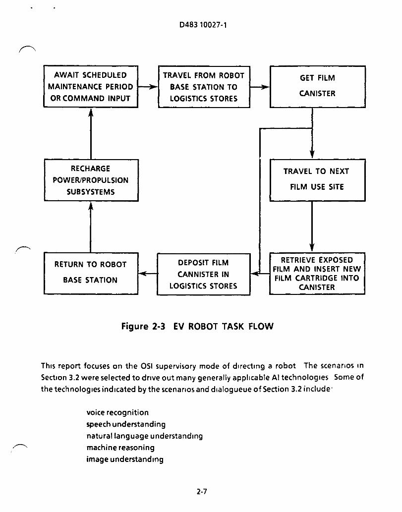
2-3 illustrates a Simple sequence of tasks that could be executed by an EV robot.
"...-.. (
2-5

ILLUMINATION SOURCE
STEREO VISION (21
WRIST
SHOULDER • PITCH .YAW
• PITCH • ROLL • YAW
FILM ~ •~/'/
CANISTER" ,
AL TERNATIVE END EFFECTORS
WAIST ·PITCH • YAW
ANKLE • ROLL
D48310027-1
~ STABILIZER "LEG"
NEVA HANDHOLD" GRABBER
OMNI DIRECTIONAL ANTENNA (21
NECK • PAN/TILT • YAW • PITCH
DETACHABLE N2 PROPULSION UNITI POWER PACK
"ARM" STOWED
Figure 2-2 AN EXTERNAL ROBOT CONCEPT
048310027-1
AWAIT SCHEDULED TRAVEL FROM ROBOT GET FILM MAINTENANCE PERIOD _ ... BASE STATION TO ... ,. -OR COMMAND INPUT LOGISTICS STORES
CANISTER
RECHARGE TRAVEL TO NEXT POWER/PROPULSION
SUBSYSTEMS FILM USE SITE
,
RETURN TO ROBOT DEPOSIT FILM RETRIEVE EXPOSED
- CANNISTER IN FILM AND INSERT NEW
BASE STATION - FILM CARTRIDGE INTO LOGISTICS STORES CANISTER
Figure 2-3 EV ROBOT TASK FLOW
This report focuses on the OSI supervisory mode of directing a robot The scenarios In
Section 3.2 were selected to drive out many generally applicable AI technologies Some of
the technologies indicated by the scenarios and dlalogueue of Section 3.2 include'
voice recognition
speech understanding
natural language understanding
machine reasoning
image understanding
2-7

D48310027-1
adaptive data base management
expert systems
learning systems
The scenario given In Section 3.2 1 indicates the range of tasks that an EV robot could
perform to support Space Station maintenance, expenment, and astronaut EVA
operations. The dlalogueue In Section 3 2 2 describes an interactive OSI session dUring
which an astronaut provides directions for completing a robotiC task. This task, which
modifies a similar task, requires the addition of some procedures developed dUring an
experimental program.
This instruction session IS conducted by the astronaut In a work station In the Space
Station. The astronaut is interacting with a software program within the Space Station
computer system. This instruction program and Simulation will be of a fidelity that, once
the task is demonstrated to be understood, the instructions can be stored, appropriately
assembled with other tasks, and downloaded to an EV robot prior to the time the task IS to
be performed
When the robot leaves Its berthing area It will have a schedule of tasks to perform, a
travel path calculated to reach the task sites; a 3-D map of the static Space Station; and
the intelligence to perform some deViations from the preprogrammed plan For example,
It will have sensors and communication means which will keep It Informed of ItS location
and other objects moving In the proximity of the Space Station. The robot will be
provided With colliSion aVOidance procedures which will permit some plan deViation and
stili maintain autonomous operation. As the EV robot performs ItS tasks It will be able to
report to and receive commands from the astronauts and the Space Station computers
One of the most significant conSiderations In defining thiS OSI concept IS the use of
astronaut time. The OSI must accept high-level, verbal and graphiCS Instuctions that can
be Input by the astronaut qUickly and Simply. Another conSideration IS the variation that
would be Inherent In each astronaut's delivery of high-level directions The OSI would
need to have a natural language capability adaptable to all of the anticipated human
users.
Section 4.0 of thiS report gives a technology assessment that was performed by the BCS AI
center. The assessment presents an evolutionary sequence for the development of A&R
2-8

048310027-1
technologies from the present to about 2010 The concepts described in Section 3.2 would
fall Into the Phase 3 of the assessment, as discussed In Section 4.2.3.
The question of teleoperatlon versus autonomous robot evolution has been raised and is
discussed in some detail by Section 4.4.
The conclusions resulting from this study and a recommendation for an 051 advanced
development program are Included In Section 5.0.
2-9

D483 10027-1
3.0 DESCRIPTION OF TH E 051 FOR AN EV ROBOT
This Section describes the tasks that would be performed by a mature EV robot system;
tasks that represent a significant pull on AI and robotiC technology. These tasks are
Illustrated by two scenariOS, one describing a full day's work by an EV robot and the other
descrlbmg a task planning dialogue between an astronaut and the 051. These scenarios
are followed by a description of some of the operational requirements for an EV robot/OSI
system, including 051 communication functions, task planning and scheduling, and
anomaly management
3.1 Critical and Routine Tasks
The reasons for uSing robots on the Space Station are to relieve the crew of tlme
consuming, potentially hazardous, and highly repetitive tasks The Critical tasks to be
performed by an EV robot, such as handling hazardous materials, performing extended
EVA operations and assisting with superhuman precIsion adjustments, are the deSign
drivers exerting the most technology pull on the OSI system
In addition to Critical tasks, the EV robots can be expected to perform tasks that are day-to
day, predictable, well-defined, and repetitive housekeeping chores. These tasks, which
Include inspecting the Space Station exterior for damage or wear and removing
contamination from exterior surfaces, do not represent an optimal use of crew time when
performed through EVA. The unproductive "overhead" time reqUired to SUIt up, gather
materials, travel to and from the task Site, and unsUit after the task IS done, may well
overwhelm the time reqUired for the task Itself.
Another set of routine tasks well within the postulated capability of EV robots IS
experiment support. Many Instruments used In space experiments will require routine
servIcing such as replenishing consumables, replacing focal plane Instruments, changing
film cannlsters or optical filters, and plaCing or retrieVing material samples While Similar
In reqUired capability to the housekeeping tasks, these tasks are not as basIC to EV robot
services because they are not as routine. That IS, the task requirements will change from
experiment to experiment and the plannmg and robot programming for the task will
probably have to be done on-station. Therefore, the savings In crew time are not as great
as for automating housekeeping functions. These tasks will also depend on the eXistence
of Space-Statlon-deployable, task-Oriented planning software for the EV robots.
3-1

D48310027-1
In addition to performing critical and routine tasks, EV robots may also be able to serve as
crew assistants. A mature EV robot could be used as an assistant to a human crew member
In addition to performing tasks autonomously. These capabilities could reduce the
frequency or duration of EVA or reduce the number of crew members needed for some
EVA tasks. One of the simpler crew support applications, which may be possible with a
rudimentary EV robot system, IS to use a robot to provide a remote view of a potential EVA
site. The Space Shuttle has used a TV camera mounted on the remote manipulator for a
similar application A robot carrying a TV camera or other sensor could be dispatched to
provide crew vlslbllty of a remote site to aid In EVA planning The robot could also
continue surveillance dUring EVA as a sensor for the crew member(s) mOnitoring the EVA.
In a more sophisticated assistant application, the EV robot could act as a caddy, tagging
after the EVA crew member, carrying and fetching tools and materials. The highest level
of assistant task IS for the EV robot to act as an extra set of hands In positioning tools and
materials and to lend strength or precIsion to the crew member.
The OSI between the EV robot and Space Station crew will evolve as robotics tasks become
more complex. The OSI features that will be needed frequently, such as the
communication functions discussed In the next Section, must be at the crew's fingertips
and not Just at a centralized command and control station. If a crew member must travel
to a central console to Issue frequent commands to a robot performing routine tasks, the
time-savings of uSing the robot may be lost. Therefore, a portable remote
communications system will be required. As the robot technology becomes more
autonomous, the frequency of communication will probably decrease. The third level of
tasks deSCribed above will require a natural language Interface to on-line task plannmg
and control. Such capabilities will certainly not be available when the EV robot system is
used initially and will prOVide a Significant technology pull on AI and robotiCS.
3.2 Scenarios
The followmg two scenarios Illustrate how a robot might perform some of the types of
Space Station-related tasks deSCribed previously. The first scenario summarizes a range of
tasks that could be performed during one day, and the second scenario Illustrates an OSI
sequence between a crew member and the task planner for a relatively autonomous
robot. These scenarios were created to establish an innovative Idea envelope within which
the conceptual deSigns could be developed and to which the forecasts for technologies
3-2

,~
(
D48310027-1
necessary to support an EV robot 051 development could be addressed. The events are
extrapolated from what could be possible, based on the current state of the art, by about
2000 to 2010.
3.2.1 Full Day Scenario
This scenano IS presented to indicate the range of tasks that an EV robot might perform
for the Space Station It provides the setting for our 051 concept definition.
One morning after a busy night of tasks, the task planner (computer) creates a schedule of
tasks for the robot, which are denved from the follOWing requirements list
• A sensory expenment requires a bad card changeout - URGENT
• An observation expenment requires a film pack change.
• Two expenments require battery pack changeout
• •
Two expenments require routine calibration
One expenment has mounting problems - needs examination - astronauts
had requested further examination from prevIous day
• One astronaut requests 1.5 hours of robot time to assist In EVA task from
0930 - 1100 • Internal preventive maintenance penod must be conducted.
The schedule created leads to the follOWing events
0700 --
0730'--
0750.--
0810.--0825.--
Robot performs routine self-check tests (replaces one JOint servo that Isn't
Within tolerance -logs change)
Robot loads up With propulSion pack, 1 film cannister, 2 battery packs, 1
computer card, calibration test equipment
Robot moves toward first task (begins sensor observation of exterior while In
transit). DUring observation notes 3 configuration differences - places
message for astronaut review
Arnves at sensor expenment - replaces bad card
Selects path to next task BeginS movement toward next task (starts sensor
observation of extenor). Notes 2 anomalies Expert system determines 4 of
3-3

0836'--
0844.--
0850:--
0915:--
0930.--
0950:--
1025:--
1100.--
1145. - -
1153. --
1217:--
1226 --
1229'--
1247 --
1308. --
1344' --
D483 10027-1
the 5 anomalies found so far are near the damaged sensor which was just
repaired Initiates low-level annunciation signal for astronaut alert.
Arrives at expenment - changes battery pack.
Selects path to next task. Moves toward next package (because of proximity
to current location, no exterior observation).
Arrives at experiment, Earth observation camera E16B - changes film.
Robot moves to airlock to load up with tools required for EVA assistance task,
places exposed film In airlock for astronaut attention, and changes out
propulsion/power pack.
Robot arrives with astronaut at EVA operations site
Another robot JOinS task to perform 'gofer' functions
Robot provides spotlight Illumination for astronaut as Sun sets
Robot senses sunrise and turns off spotlight.
EVA task ends. Astronaut Interrupts schedule - asks robot to return to area of
damaged sensor (repaired earlier). Robot performs detailed inspection under
direction of two astronauts It appears that a mlcrometerolte may have
caused damage. Astronauts deCide to perform EVA at 1300 to further
examine area and select any necessary repair options. The robot's presence IS
requested, which causes the task planner to update the schedule.
Robot selects path to nearest task (turns on observation sensors while
traversing - no discrepancies noted).
Arrives at experiment - performs calibrations.
Selects path to next task - observes exterior while traveling.
Changes battenes on experiment
Selects path - warned of OMV approach In proximity of task - walts for
completion of OMV docking
Moves off to next task - observes exterior
Arrives late at EVA inspection site Had been monitoring astronaut progress,
but calibration had taken longer than planned, and astronaut had arrived
earlier than projected - error noted forfurther scheduling considerations.
Astronauts deCide repair will be performed later In week after more time has
been given to assessing and preparing repair options
At thiS pOint, there are no other Immediate tasks for the robot to perform or assist on.
However, the task planner has a number of functions stored that are either standard
3-4
------.. \

048310027-1
f".. servIcing requirements that need to be Integrated Into the robot's schedule or are new
requests that were Issued when the robot was occupied but that didn't require an
interruption because there was no specified time. The following IS a list of these
outstanding requests, which IS followed by a task scenario that shows how they are
integrated Into the next segment of the robot's schedule.
New requests
• Assist a crew member In positioning an experiment package. MRMS will also
be used. Robot to prOVide additional eye pOint
• Clean exterior surface of Window C within the next 36 hours to accommodate
an Earth-observation photo session from station interior. Location of smudge
on window noted.
Unscheduled maintenance/support tasks
• •
Perform preventative maintenance on 2 experiments based on trend failure
analYSIS
Repair a piece of hardware on the solar arrays based on analYSIS indicating
excessive degradation
• Complete an Instrument calibration based on projections of a busy schedule
when the normal calibration would occur.
• Survey sector 30-2 sub 6. ThiS IS required because no recent activity has
occurred In thiS VICinity.
1345: --
1353:--
1403:--
1412:--
1435 --
1457:--
1503:--
1509: --
Robot moves to home lock area
Unloads equipment used on prior tasks and SWitches out power packs Loads
up With maintenance tools.
Moves to first experiment site.
Begins maintenance (cleaning, adjustment, replacement).
Moves to 'early' Instrument calibration via sector 30-2 sub 6. Performs
exterior survey dUring traverse.
Performs calibration of Instrument package
Receives message that astronaut-assist task will begin at 1530
Moves to site of astronaut-assist task.
3-5

1518.--
1530'--
1610'--1623:--1637:--1648:--1701:--
1743:--1754:--1827:--1841'--1852'--1908 --1923.--
2003.--2121 --2139 --2153:--2204 --2217'--
D48310027-1
Arrives at site early Notifies crew of arrival, goes Into background mode
while awaiting task start.
Provides mobile "flYing" eyepolnt for MRMS maneuvenng. This mobility is
directed by natural language/communication techniques.
Robot sWitches on spotlight to provide Illumination.
Task completed. Returns to home lock area for window cleaning equipment.
Unloads equipment, picks up cleaning tools.
Moves to window.
Cleans window Astronaut happens to be In area and sees task Interactively
suggests additional spots on window that need attention.
Moves to next task
Performs routine preventative maintenance task.
Returns to home lock.
Unloads equipment Selects tools for solar array repair.
Moves to spares storage lock area.
Collects array parts that Will be replaced.
Moves to solar array area requlnng attention. Reduces speed when near
array to reduce danger of collision and minimiZe contamination; continually
senses array location as It rotates
Begins repair of structure
Moves to SCIentific Airlock #2L (Large)
Unloads degraded struts and mirrors (for later analysIs by crew)
Moves to home lock
Plugs self In. Nothing urgent on schedule, performs Internal checks
Task-planner schedules next series of tasks from low-prlonty lists. Notes
restriction that crew will be bedding down for night shortly and that the
habitat module Will be off-limits for outside maintenance.
3.2.2 Operator/System Dialogueue
The first scenario showed the types of EVA a highly developed robot could perform to
support the Space Station crew. Based on that kind of support function, the follOWing
SCript represents an 051 "dlalogueue" between the EV robot system and astronaut that
shows how the 051 instructions are conveyed
3-6

~
~
048310027-1
Let's examine In some detail how the robot task planner IS directed to program a change
to the task listed at 0850 In the first sceneno. The astronauts are Installing a new camera
to perform Earth-sensing photography. Before the camera becomes operational, a
member of the crew must conduct a dialogue with the software that develops task plans
for the robot. This software, which will be contained In the Space Station's computing and
data management system, would have access to a CAD database descnbing the station
and ItS equipment It would also have access to eXisting robot task plans and to Simulation
and graphiCS software.
The result of the dialogue between the crew member and task planning software would
be a new set of instructions for an EV robot. These instructions would have been
developed and verified cooperatively by software and the astronaut and demonstrated by
Simulation. A crew member would probably observe the first execution of the new task to
further venfy the task plan. The dialogue would be along these lines:
Astronaut
Audio
Astronaut
Computer Display
Astronaut
Astronaut
Audio
Astronaut
Computer Display
Astronaut
Audio
Astronaut
Audio
"Hello, Task Planner."
"Task Planner here."
"We need a new film cannister exchange program at thiS location;
computer graphiCS please"
(CAD solids model version of Space Station IS brought up)
Rotates and frames display to show robot's berth and the location
of the work site
"Note the location" -- points to the work site location with
pOinting deVice.
"OK. "
"The cannister IS for the E16C camera, which IS like the old E16B;
computer comparison graphiCS please."
(Color coded CAD solids models of the E 16C and E 16B cameras are
overlaid).
"Note that the door IS shaped differently please;" rotates the
display Simultaneously
"OK."
"The latch mechanism operation IS different, note please," POints
to latch mechanisms with pOinting deVice.
"Show me."
3-7

Astronaut
Computer
Audio
Astronaut
Audio
Astronaut
Audio
Astronaut
Audio
Astronaut
Audio
Astronaut
Computers
Astronaut
Audio
D48310027-1
"The new latch IS the same as the experimental version we used on
test 0178-V3 computer, run simulation with graphics please, Task
Planner, note please"
(Runs simulation of the operation of the latch mechanism and
displays the sequence).
"OK."
"The work site area IS the same as before."
"OK."
"The photography schedule IS the same as the G33A we ran for the
E16B"
"Start date?"
"Day after tomorrow"
"OK."
"Notify me when each exposed film cannister IS ready please"
"OK."
"Play that back please"
(Runs simulation of task displays travel, task; elements, and
schedule)
"Looks OK, store please"
"Task Planner, OK and out."
3-8

D483 10027-1
3.3 OPERATOR· SYSTEMS INTERFACE
The dlalogueue presented rn Section 3 2 2 descrrbes an OSI that uses several advanced
technologies. This Section discusses each of those technologies from a functional pornt of
view. The OSI system that IS Implied rn the discussion rncludes an rnternal robotic
computer and embedded software, a centralized Space Station computer (task planner or
scheduler), and related, supportrng functions of the onboard Space Station data
management system
3.3.1 Communication Functions
The operational philosophy for the OSI will be to provide a natural communication Irnk
between astronauts and the onboard computer system rncludrng the robot. For the
astronauts, natural communrcatlon means rnput of data and commands usrng methods
such as speakrng and porntrng, and recelvrng feedback through visual and aural channels
To the computer and Its associated perrpherals, natural communication Implies the
~ necessary hardware and software required to accept from and express data to the
~ (
astronauts rn a lucid manner, rndeed, the hardware and software should be transparent
(I.e, unambiguous) to the user The astronaut should not be required to learn a new
language or rrgld command syntax rules.
The dialogue given rn Section 3.2 2 represents an OSI concept that uses this natural
communication philosophy. The conceptual design descrrbed below delrneates the
components and operational requirements of each OSI element However, the descrrptlon
does not rnclude component layout, 051 geometry, or hardware specifications The
components envIsioned for this 051 rnclude color graphic displays, vOice recognition and
synthesIs, and nonverbal communication links (keyboard, hand controller, and touch
rnputdevlce).
3.3.1.1 Displays
Plctorral and graphics displays Will be the prrmary method for presenting visual data to
Space Station crew members, although some control operations may require direct
vlewrng These displays must rntegrate data rnto an easily comprehendible format to help
the operator understand and act on the data presented Studies have shown that 90% of
the rnformatlon we process IS received through visual data, most of which IS perceived as
3-9

D48310027-1
objects, not words or numbers. Therefore, the displays will present mostly dynamic or
static pictorial graphics presented In real time, which will be supplemented by
alphanumeric data. The displays may be presented on a large flat screen (as opposed to a
CRT) at a central control station and on smaller portable screens that will be part of the
remote, pOSSibly hand-held 051 communication link.
There are two 051 display concepts -- head-up (HUD) and holographIC displays -- that
would not be required for the dlalogueue presented In Section 3.2 2 but should be studied
In more detail. A head-up display (HUD) is an Instrument that projects computer
generated dynamiC symbology onto a clear combining surface mounted In the operator's
field of view (FOV), thereby overlaYing the symbology on the Viewed scene. The operator
then can have all necessary information In the Immediate FOV, decreaSing eye
accommodation and attention diverSion problems. A head-up display could be used for
both IV and EVactlvltles.
A holographIC display presents a true three-dimenSional representation of an object or
situation to the viewer ThiS type of display would be useful for flight operations, to
simulate a repair task, as a teaching/learning aid, and to evaluate construction techniques.
ThiS technology requires some pushing and direction for thiS applICation. The speCIfic
areas of concern In uSing holographIC displays Include power consumption, processing
time, and real-time processrng techniques.
3.3.1.2 Voice Recognition and Synthesis
The vOice recognition system Will be used to send commands to the computer and robot.
It will prOVide the astronaut With a natural means of communication - the spoken word.
The same commands could also be entered through a keyboard or touch rnput deVice. To
truly meet the natural communICation requirement, the recognition system Will have to
accommodate a fleXible syntax for messages from the crew, although conventional rules
of grammar Will be observed. The system must also recognrze contrnuous speech, allOWing
recognizable words or phrases to be spoken at a natural rate The system Will be deSigned
to recognize a speaker by requestrng the speaker to recite selected phrases whICh are
recorded by the system. The recordrngs Will then be analyzed for speaker-unique
pronunCIation of the phonemes rncluded In the selected phrases and these phonemes Will
be compared to the standard phoneme database whenever the speaker Issues a command.
3-10

(\
D48310027-1
The companson will allow the system to Interpret the speaker's command. This technique
minimizes the expenditure of crew time for both system training and use.
The recognition system must also be speaker-Independent and speaker-adaptive.
Speaker-independent means that the system will recognize a large number of speakers
without losing accuracy However, a speaker will be required to Identify him or herself for
recognition and secunty purposes when first uSing the system Speaker-adaptive means
that the system IS flexible enough to recognize a speaker dunng vanous stress levels of the
speaker's vOice.
As the dlalogueue showed, the astronaut gains entry Into the task planning mode for the
robot by simply saying, "Hello, Task Planner." This indicates that the 051 recognizes the
astronaut's vOice and determines that the astronaut IS a valid person to give task direction
to the robot. The astronaut speaks conversationally and, In fact, doesn't use the most
quantitative speech possible: he says "day after tomorrow" for the start date, rather than
a specific date The 051 system correctly Interprets the Input, emploYing what It "knows"
about that particular astronaut's use of the language so that the "day after tomorrow" IS
In Earth calendar days, corresponding to the astronaut's sleep-wake cycle.
A vOice synthesIs system IS a natural communication means between the computer and
robot, and the crew USing vOice synthesIs as a feedback to the crews offloads their
already overloaded visual channel and Increases the usage of the traditionally
underloaded aural channel. To allow the greatest flexibility, the synthesIs system will also
be phoneme-based. The system will create words by uSing the phonemes In the database
In addition, the vOice-type, (I.e., malelfemale, accent) will be selectable by the crew
The 051 system synthesises audio responses which may, as shown In the dlalogueue,
initially be somewhat structured. As the system progresses, the audio responses would
preferably be unstructured and, In fact, be intentionally changed to indicate real
understanding ofthe directions received.
3.3.1.3 Data Display and Exchange
The astronaut and robot/OSI system simultaneously evaluate CAD data The computer
system, on vOice command from the astronaut, bnngs up the designated CAD data for
display. In reaction to inputs from the astronaut through advanced Input devices (I e.,
3-11

D48310027-1
light pens, display pressure pOint application, etc.), the computer manipulates the CAD
data The OSI "observes" the data In real time and reacts to the astronaut's "Note the
location", as the astronaut indicates the displayed location with a pOinting device.
To show comparisons graphically, the computer presents data for color-keyed displays
with overlays and the system IS able to Interpret the distinctions In real time The OSI IS
also able to distinguish, In near real time, where things are the same or different by
reviewing the data presented as the astronaut observes and manipulates the graphic
display
The computer system runs a simulation of sequences selected by vOice Input from the
astronaut and simultaneously displays the results graphically The OSI system receives the
data from the simulation as It IS run and displays and Interprets that data to Identify
features needed for the robot's task description. The OSI determines If the data IS
complete and consistent with the rest of the task description for an "OK" conclusion about
the Input
3.3.2 ROBOT TASK PLANNING AND SCHEDULING
The tasks that will be performed by the robot on orbit will be sequenced, Integrated, and
Prioritized by the computerized task planner, In conjunction With commands Issued by the
crew through the OSI For example as we indicated In the first scenariO, the mature robot
will be able to function fairly autonomously In response to a preset schedule of tasks, In
addition to being able to Integrate unscheduled, routine tasks and emergencies ThiS task
planning capability will be preceded by simulation to aSSimilate the time, lOgiStiCS, and
procedural elements of the subtasks, which will be modified and updated as they are
performed on orbit. The task planner, or scheduler, will receive Inputs continuously from
the crew and other computers, which will Impose new requirements and constraints on
the eXisting schedule Tasks that require Immediate action will Interrupt the eXlstmg
sequence of events Each task Input will have to take Into account the completion time
needed, paths of travel between tasks, and the resources that will be reqUired to fulfill a
task or schedule sequence (tools, power, fuel, parts).
The task planner will also have to integrate information on other objects (Orbiter, OMV,
OTV or free-flyers) maneuvering In the proximity of the Space Station or task area, In
addition to any environmental constraints such as radiation emiSSions, Signal blockages,
3-12

D48310027-1
f"'- potential contamination sources (such as a thruster firing), and possible crew sleep
disturbances.
The robot will perform It'S scheduled list of tasks either autonomously, checking for
updates and changes after completing each task unless Interrupted, or It may be Involved
In a direct astronaut/robot cooperative function, responding to Immediate requirements
as discussed In Section 3.1.
The popular definition of intelligence Includes the ability of an entity to learn from
experience and avoid making any drastiC mistakes. It IS doubtful that a Space Station
robot will be given full autonomy until It has such "intelligence" Confidence In the
robot's "knowledge" will be gained by Simulating many Situations, including those In
which an operator purposefully makes errors. A safety and sanity (S/S) mOnitor program
should be developed concurrently With other robotiC programs. ThiS SIS mOnitor must
have the ability to extract rules to cover Similar future situations either directly by
observation or, more likely, by means of interviews and conversations With operators
,~ 3.3.3 ANOMALY MANAGEMENT
While the robot may have increasing autonomy as crew confidence mounts and
technology advances, there must stili be a means for alerting the crew of faults and
anomalous Situations when they occur. An effective crew alerting philosophy should meet
the follOWing two general obJectives·
1. Minimize the time reqUired for the crew to detect and assess failure
conditions and to initiate correction actions, and
2 Conform to the qUiet, dark OSI concept when all systems are operating
normally.
Faults and anomalies should be categOrized by the safety/sanity monitor Into four major
classes, each class eliCiting a predefined alerting scheme. The first class IS
information/maintenance data, which Include system trend data, maintenance log, etc
and do not require Immediate crew action or awareness No aural tone IS eliCited but a
1/'"-' discrete indication (green/white) IS given Visually, (as shown In Section 3 2 1 at 0750). ThiS
data can also be recalled by the crew The next class IS adVisory data, which Include
3-13

D483 10027-1
operational or system conditions, that require crew awareness and may require
subsequent or future crew action. A promment alphanumeric display (unique color)
descrlbmg the advisory is provided, as well as a unique aural sound (see Section 3 2.1 at
0825) The third class IS caution data, which mclude abnormal operational or system
conditions that require Immediate crew awareness and subsequent corrective or
compensatory crew action. A master visual (amber) mdlcatlon, a promment alphanumeric
readout (amber), and a unique aural sound and vOice message are Issued. The last class IS
warnmg data, mcludlng emergency operational or system conditions, that require
Immediate corrective or compensatory action by the crew. This mcludes all time-critical
faults A master visual (red) mdlcatlon, a promment alphanumeric readout (red), and a
unique aural sound plus vOice message are elicited These four classes are broad enough
to encompass any forseeable fault or anomaly, and provide consistent nonconflgurmg
crew-alertmg procedures
As mentioned earlier, the safety/sanity mOnitor would categorize the faults. In addition,
the monitor would Prioritize detected faults, Implement a safe and hold logic for critical
Situations, and broadcast a message for the fault to alert the system. The monitor reduces
the number of crew alerts by solvmg mmor faults and anomalies and thereby generally
off-loads the crew and mcreases their confidence m autonomous system operations
Another area of anomaly management mvolves situations during which a robot has
difficulty with a prescribed procedure, or fmds that a piece of hardware at a work site
differs from that expected To some extent, a hierarchy similar to the alertmg scheme can
be followed m these situations For any situation mvolvmg a Ilfe-threatenmg or tlme
critical task the crew should be notified Immediately Simultaneously, the robot system
searches ItS own memory for a solution. If the situation IS not Ilfe-threatenmg or tlme
critical, the robot should eventually be sophisticated enough to search for a solution
autonomously and, only after exhausting potential solutions, notify the crew The
solution search process would mvolve the safety/sanity mOnitor as well as the robot's
memory
3-14

D48310027-1
4.0 TECHNOLOGY ASSESSMENT
Section 3.0 described the capabilities of the 051 that would support a fully autonomous EV
robot system This section begins by describing the technology assessment used to
examine the feasibility of this 051. Section 4.2 then uses the description of section 3 0 and
results of the technology assessment to develop a three phase approach to EV robot
autonomy. The technology advances required by each of these phases define the
technology pull Imposed by the Space Station EV robot 051. Section 43 compares the
technolgy pull defined In section 4 2 to estimates of technology availability to define the
technology push that must be applied to develop the EV robot 051. Section 44 discusses
an alternative evolutionary path for the EV robot, that of bUilding on current
teleoperated robot technology, and concludes that a path based on partial autonomy IS
more likely to lead to a successful EV robot development.
4.1 Technology Assessment: Project TAARGET
f'\ Technology can be defined as a set of pragmatic prinCiples, processes, and techniques
derived by humans and Intended for the manipulation and/or control of phYSical reality,
including the reality of human-produced objects As defined, It IS clear that technology IS
a pragmatic disCipline or methodical effort, but not the results of such effort. Thus,
structures, tools, machines, or any other artifiCial object IS an artifact of technology, but
not technology Itself. However, artifacts can be used to estimate the status of the
development of technology, thereby forming the basis for technology assessments
A technology assessment (TA) IS a set of statements and associated illustrations that
describe the current and/or projected development status of a particular set of pragmatic
prinCiples, processes, and techniques by uSing the artifacts of same. A comprehenSive TA
requires an examination of current literature, consultation With experts In the technical
area being assessed, and sophisticated forecasting and statistical methods to Infer the
future of the technology. Fortunately, a recent, full-scale assessment of robotiC
technology was available to support thiS study. Boeing used the Transnational Assessment
of Autonomous RobotiC Generational and Evolutionary Technology, (TAARGET), as a
source of technology assessment for two reasons: because time constraints did not permit
,,--...- an Independent, company-sponsored, effort; and the perceived excellence of the
TAARGET effort Itself.
4-1
D483 10027-1
PrOject target IS described m Section 4.1 2
4.1.1 Factors Influencing Technology Development -- Push and Pull
The direction of a given technology IS largely controlled by technology pull; that IS, by
operational and/or systems requirements the fullfiliment of which necessitate the
generation/development of relevant technical dlsclplmes, products and processes.
Technology pull starts with a set of operational requirements that serve as a necessary, but
not a suffiCient, condition for developmg new technology These requirements are usually
generated by the "customer" (e g , government agency, mdusty, organization, mdlvldual,
etc) and are usually a set of generic operations that a system Will be expected to perform
and agamst which It will be ultimately tested. Each one of these operational requirements
must be translated mto a detailed set of functions to be performed by any specific system
expected to meet the operational requirements These functions are known as functional
requirements They are mdependent of specific technologies m that more than one basIc
technology could be made to perform the functions dictated by the set (e.g., discrete vs
mtegrated circuits).
The next step translates functional requirements mto a set of generic technology
requirements (GTR) These mayor may not be specific-technology mdependent They are
"clusters" of mterrelated technologies that can be used to perform major subsystem
functions (e g , the mertlal measurement unit or the gUidance computer m a spacecraft or
ballistic missile)
The fmal step IS very technology specific Where possible, It Identifies specific techniques
and processes that are mature enough for Immediate support of the preViously Identified
GTR's, functional, and operational requirements It may also Identify techniques or
processes that are not mature enough to meet these requirements. In that case, the
requirements are said to "pull" the as-yet Immature technology
ObViously, technology pull IS a polar concept that must be considered m relation to ItS
Opposite, technology "push", those relevent technical and/or socleconomlc events that
~\
affect the arrival (maturing) time of a new technique or process. SOCleconomlC events are ~
usually characterized by,
4-2
D48310027-1
1) Generation dynamics: the elapsed time between one generation of a particular
technology and the next
2) Technology transfer time: the elapsed time between one major area of
application and the next
Both can be accelerated or decelerated by political and/or economic events.
Predictive technology assessment tries to determine whether the push will equal the pull
Within a given lapse of time. As With TAARGET, the most credible assessments perform
thiS determination quantitatively.
4.1.2 Project TAARGET
Some TA's are descriptive and/or cursory, others are sophisticated, quantitative statements
regarding a particular technology. The TA for thiS study IS derived from TAARGET, a large,
methodologically quantitative, study of intelligent robotiC technology ThiS study was a
/-----, three year, $12 million, international investigation that used the latest, most refined
techniques currently available for a technology assessment The original TAARGET report,
as well as It'S 1983 update, are under prlvlledged title.
~
I
Data Sources
The TAARGET data sources are relevant documents as well as Interviews With qualified
non-Sovlet-Block oplnlonators around the world. Twenty-two thousand documents
related to research, development, and application of intelligent robotiC systems and
subsystems were examined and analyzed by people technically trained In the material
being examined. Documents/papers In French, German, Italian, Japanese, Swedish, and
English were examined to determine their Implications for technology development. The
analyzed material was used to structure an interview program to confirm/disavow the
hypotheses generated by the document analYSIS.
The prinCipal tool used In the interview program was DELPHI - 14. ThiS Instrument
permitted covert interviewing while generating reliable worst, best, and most likely time
and performance estimates for subsequent Input to the DeCISion Impact Risk Evaluation
and Control Technique (DIRECT) Simulator, which IS discussed later.
4-3

D483 10027-1
One of the critical Issues m developmg a reliable consensus IS the reliability of the
opmlonators consulted. A set of metrlcs were developed and tested on a random set of
opmlonators. These were found to be highly accurate in separating unreliable
opinlonators from reliable ones The metrlcs were applied to a population of 4600
potential opmlonators in the free world Of these, 2000 were selected for mterview. The
greatest care was exercized by the project TAARGET team to ensure the reliability of ItS
data sources.
Data Evaluation Methodology
After appropriately reliable data was obtamed, It was processed by the risk assessment
Simulator, DIRECT, that was developed and refmed durmg the late 1960's and early 1970's.
As mdlcated m Figure 4-1, the mput format IS that of distributions taken from the DELPHI
exercise. These are then piecewise convoluted and the termmal distribution IS processed
by a set of speCially developed risk equations Some of the outputs from DIRECT are given
m Table 4-1. A tYPical example of a preliminary output from DIRECT IS given m Figure 4-
2a. A related, derivative output IS shown m figure 4-2b. Both of these outputs are
parameters m a quantitative reliability technology risk assessment
4-4

RISK ELEMENT "A"
,
DISTRIBUTION
III(
TERMINAL ~ ...
DISTRIBUTION
~ (
D483 10027 - 1
+ RISK ELEMENT "B"
.... PIECEWISE
DISTRIBUTION r---.. CONVOLUTIONS
RISK RISK .. EQUATIONS ASSESSMENT
Figure 4 - 1 DIRECT: MAIN PROGRAM
4-5
TOTAL RISK
ERROR
~ CONTROL
l

D483 10027 - 1
1) COST 'SCHEDULE' PERFORMANCE RISKS 2) RISK BUDGET FOR EACH ITEM OR SUBSYSTEM TO BE DEVELOPED' PRODUCED 3) CONTRACTOR FEE ON ANY TYPE OF INCENTIVE CONTRACT 4) RISK OF MAKING TARGET FEE' PROFIT ANY TIME DURING CONTRACT FULLFILLMENT 5) TOTAL PROGRAM IMPACT OF RISK ITEMS 6) COMPARATIVE EVALUATION OF RISK ABATEMENT STRATEGIES 7) OPTIMAL ALLOCATION OF RESOURCES (MANPOWER, DOLLARS) 8) RISK OF REACHING PROJECTED TECHNOLOGY GOALS 9) RISK OF MAKING A TARGET RETURN ON INVESTMENT (ROI)
10) PRESENT WORTH AND RISK OF PAY BACK PERIOD 11) MERGER RISKS 12) RISKS AND RISK IMPACT ASSOCIATED WITH CHANGES IN PERFORMANCE REQUIREMENTS
Table 4-1 PARTIAL OUTPUTS FROM DIRECT
, , , , TIME
, , , , , , \ I I
PERFORMANCE I
I I I I ______________ J
I I
RESOURCES (COST,
I MANHOURS, ETC) I
Figure 4-2a
INTERRELATION OF RISK PARAMETERS
4-6

~ I
r--, (
PROB
MEETING
MTBF
1.0
D483 10027 - 1
TIME
(YRS)
Figure 4 - 2b TYPICAL DIRECT OUTPUT
(MTBF)
(MTBF)
(MTBF)
DIRECT uses these preliminary results to simulate a PERT (or GERT) network with which
Impact analyses are performed. These Involve quantitatively IdentifYing the Impact of
socio-economlc events (technology push conditioners) upon the rate of development to be
expected from a given technology under differing soclo-economic conditions. The results
4-7

D483 10027 - 1
of these analyses are usually a set of charts displaYing best, worst, and most likely years In
which differing types of demonstrations of the particular technology are to occur.
Most sophisticated predictive technology assessments use a set of well-defined event to
define the maturity of a technology Demonstrations are palpable events In technology
development so the TAARGET study used a set of demonstrations to predict technology
status. The types of demonstrations of a particular technology for which DIRECT predicts
future status's are given In Table 4-2, together with the defining characteristics of the
demonstrations
•
•
•
•
CONCEPT FEASIBILITY Usually Stand Alone Usually Non - Real Time Crude, Undeveloped Interface(s) No Form, Fit Optimization
MATURE LABORATORY PROTOTYPE Pulled by Clearly Defined Technical Objectives Frequently Embedded Usually Real- Time Interfaces Defined and Developed Can Function as Proto - Engineering Baseline Specific Potential Applications Can Be Defined
- Accurate Quantitative Development Risk Assessments Possible DEVELOPMENT ENGINEERING A
Evolving Design Constrained by Form, Fit and Economic Constraints
- Well - Defined, Well - Developed Interface(s) Real- Time Frequently Embedded Operational Parameters Testbed
PREPRODUCTION PROTOTYPE .. Direct BasIs for FAB and Assembly Requirements Direct BasIs for Production Cost Estimates Field Testable Against Contracted Operational Requirements
Table 4 - 2 DEMONSTRATION TYPES AND CHARACTERISTICS
4-8

D483 10027 - 1
~ 4.2 Summary of the OSI Technology Assessment
TAARGET results, suggest that It will not be possible to deploy a fully autonomous EV
robot and OSI by the time of Space Station lac. Therefore, we have defined a three phase
approach to development of the EV robot and OSI. These three phases are marked by the
technology pull of three separable sets of operational requirements The system
deployed at lac will have suffiCient autonomy to provide significant benefit to the Space
Station crew. As time passes the system will evolve Into the fully autonomous system
described In Section 3.0. Table 4-3 characterizes the initial and final states of thiS system.
1995 •
• • • • • • • • • • •
2010 •
Receive and understand an expanding set of question andlor command sequences. Report inability to execute a command sequence. Report valid reasons for inability to execute a command sequence. Report location. Report Intended movement from one task space to another Report Orientation In task space. Report status of own su bsystems. Report fault-Intollerant failures Receive, understand, and verify objectives menu Report plan of accomplishment (Po of A). Receive and understand corrections to P. of A. Infer and report Intended changes In menu sequencing, With reasons. Identify and describe emergency Situations
Table 4-3 SCENARIO - DERIVED OSI OPERATIONAL REQUIREMENTS
(STRESSING SCENARIO)
Table 4-4a Identifies the three phases of autonomy In our plan
4-9

D483 10027 - 1
PHASES (DEGREES) OF AUTONOMY
Current Phase 1 Phase 2 Phase 3
• Human Operator • Robot In Primary • Robot IS both • Robot provides all control loop primary controller provides control and and planner own goals problem solving • Human IS Planner functions • Human provides • Human
• Robot carnes out intermediate goals controls • Full plan In sequence size and
Teleoperatlon prescribed by • Robot devises content human task to meet of goal
sUite • Human Dlsabler • Human Dlsabler
• Human Dlsabler
Table 4- 4a
GENERIC EVOLUTION OF AUTONOMY
A stepped decrease In human control and monitoring can be Inferred from Table 4-4a,.
though Table 4-4b shows this stepped decrease more explicitly and also shows a stepped
Increase In robot autonomy
Most
Least
Phase 1 (I 0 C)
Phase 2 (2000)
Human Directed,
(Low Autonomy)
Human Monitored
(Moderate Autonomy)
Phase 3 (2003-2007) Human Instruction and CrISIS Intervention
(MaXimum Autonomy)
Table 4- 4b
DEGREES OF OSI
These phases Into which the technology pull divides OSI development are based upon ~
degrees of robot autonomy These phases will, In turn, be translated Into sets of
4-10

D483 10027 - 1
('\ functional requirements, each of which IS both OSI - and Phase - specific Such translation
is accomplished In the fo"owlng Section.
r',
4.2.1 Phase 1: Human Directed
If the E.V A. robot IS expected to carry out a plan prescribed In detail by a human controller
under conditions of intelligent monitoring by that controller It must meet, at least, the
follOWing functional requirements.
*
*
*
• Receive/understand limited set of vOice question/command sequences
• Receive/understand bar code graphics also seen by human operator
• Nonvocal copy-back to operator of question/command sequence In synonymous vocabulary
• Nonvocal copy-back to operator of bar code graphics
• Infer current position and terminus coordinates for next transit
• Report location and transit Orientation by nonvocal transmission of "percelved" bar code/reflectors
• Report Orientation to task space by nonvocal transmission of perceived bar code and tactile pressure sensors
• Report completion of each step In task sequence by bar code.
Of the above requirements, the first four and the last three are OSI-speclflc. The key
technologies supporting these requlrementswere selected on the baSIS of their
evolutionary capacity. These technologies are'
* • VOice Intentionality Constrained Evaluator (VICE)
• RF/Optlcal Dual Mode Communication Link
* • Knowledge-Based 2-D Image Understanding/Semantic Processor
* • Inference Engine
* • Integration With Primary Controller
(~ These technologies were selected not only for their pullability but also because, If pushed,
they would permit a "nonscarnng" evolution With respect to the next phase, One
4-11

D483 10027 - 1
technology listed is not preceded by an asterisk. This is because It was considered by the
TAARGET team to be technologically mature
VICE IS an "interim" nonscarrlng technology being developed at Boeing's Artificial
Intelligence Research Center as well as at at least two other laboratOries overseas. It
consists of introducing a small number of synthetiC particles Into natural speech In order to
disambiguate words or phases that are normally clarified by visually observed, situational
context. Thus, If future speech understanding Involves the functions found In Figure 4-3
then such particles would be a part of the "situation pragmatics" or the error "correction
rules".
4-12

SPEECH
INPUT
AID
CONVERSION
PHONETIC
RULES OF ~ LINGUISTICS
LEXICAL
INFORMATION ~
WORD
BOUNDARY ~ RULES
D483 10027-1
Figure 4 - 3 FUTURE SPEECH RECOGNITION
PHONEMIC
LABELING
.. WORD
HYPOTHESIS
WORD
VERIFICATION
SENTENCE
HYPOTHESIS
SYNTACTICAL
RULES
SEMANTIC
RULES
SITUATION
PRAGMATICS
ERROR
CORRECTION
RULES
SENTENCE SPEECH VERIFICATION INPUT
Knowledge-Based Image Understandmg (KBIU) uses mtra- and mterframe (picture)
semantic relationships as well as some of the techniques of intensional logic to understand
the nature of a scene or series of scenes. While Image understanding technology has been
pushed by the DARPA initiative In that area, It IS stili In need of both technology pull and
corresponding push.
,- To do the logic required by the KBIU as well as making Inferences about current and I
terminal POSitions, an "Inference engine" that IS modularly up-gradable IS required.
4-13

D483 10027-1
Robot control of Its primary loop (RCPL) presupposes technology pull and push that IS
related to but apart from that of 051 For a robot to carry out the step-by-step commands
associated with Phase 1 051, It must be able to control ItS movements sufficiently to avoid
obstacles and handle complex pressure-sensitive tasks To do these adequately,
technology In the areas of T V camera-augmented Khatib control (TVKC) and LADAR
proximity sensing must be pulled and correspondingly pushed. The technology push for
both of these was addressed by the Project TAARGET team Their most-likely estimates are
given In Figure 4-4.
Figure 4 - 4 RCPL SPECIFICATION OF TECHNOLOGY PUSH FOR OSI PHASE 1
TOULOUSE STANFORD BOEING
7S A1~ 7'\
PROXIMITY LADAR (MULTIPLE SENSOR JPL FANUC GM/FANUC
SYSTEM)
ZS ATI:~ 7,\
76 77 78 89 80 81 82 83 84 85 86 87 88 89 90 91 92 93 94
4-14
~ ,

,~
~ [
D48310027-1
4.2.2 Phase 2: Human Monitored
If an EVA robot IS expected to plan and carry out intermediate goals set by a human
controller, then several machine Inteillence technologies must be pulled by these
functional requirements:
*
*
*
*
*
*
*
• Receive/understand connected speech with expanding vocabulary
• 3-D acquisition of objectives In space (with bar code backup)
• Vocal copy-back In synonymous language of all transmissions from operator to robot.
• Nonvocal copy-back to operator of all transmissions to robot.
• Plan optimal/sub-optimal sequences for fulfilling operator goals.
• Initiate and execute unplanned obstacle aVOidance
• PeriodiC recording of all robotIC subsystems status for eventual copy-back
• Robot communICates Its maintenance requirements vocally and nonvocally
• Robot perceives and communICates a limited set of cnsls conditions to operator.
Nearly all of the Items on the list are preceded by an astensk, I.e , conSidered pullers Two
that are not starred are actually derived from others on the list that are. However, only
the first, third, and fourth Items are directly OSI pullers.
The technologies pulled by these three are given In the list below.
Voice Recognition
* Speech Understanding
* Language Representation
* Natural Language Understanding
* Analogical Reasoning
MonotOnic Reasoning
* Nonmonotonic Reasoning
* Speech Synthesis/Translatlon
4-15

D48310027-1
Agarn, these were selected not only for their pullability but also because, If pushed, they
would permit a "nonscarrrng" evolution with respect to the third phase Those items
preceded by an astensk are pullable and, rn most cases, m need of technology push from
Items such as economic conditioners. Of the Items on the list, perhaps three need some
descnptlon. Language Representation, Monotonic, and Nonmonotonlc Reasonmg.
Like everythmg else perceived by humans, language must be properly symbolized m order
to be manipulated for understandmg and synthesIs. This IS particularly a problem for
machme mtelilgence If the representation uses excessive storage and processing
capability. Efficient schemes for symbollzmg and manlpulatmg stnngs of language "data"
must be devised and tested agamst human crltena for performmg the same manipulative
exercise.
"Monotonic" and "nonmonotonlc" reasonmg are synonymous respectively with deductive
logic (usually the first order predicate calculus) and the logic of belief and "hunch"
statements Both are required m order for a mach me mtelilgent robot to represent and
conceptually synthesize ItS replies to a human mterrogatlon.
It should be noted that the speech and language requirements placed upon the Phase 2
robot m order to faCIlitate OSI neither negate nor render obsolete the software for vOice
recognition developed for Phase 1. Rather, It builds upon It, Improving each of the
function boxes m Figure 4-3.
4.2.3 Phase 3: Human Instruction and Crisis Intervention
An EV robot required to prOVide ItS own goals (Within limits) and then deVise strategies to
meet these goals must not only build on the development of Phases 1 and 2 but also be
capable ofthese additional functions.
* • Learn New ..
Objects
Properties
Relations
Events
Situations (Internal/External)
Human VOice Pnnts/lmagery
4-16

*
*
*
D483 10027-1
• Autonomously Change Its Databases
Know When Deficient
Know Required Information
Know How to Reorganize File Structures
Know How to Merge/Sort
• Autonomously alter Its primary and/or secondary control loops as
functions of learning
• Repair/Maintain Itself.
All of the requirements listed above are technology pullers. Essentially the Phase 3 robot
would be a vehicular, multldemenslonal expert system. The robot's knowledge base and
Its manipulation would not only have depth and breadth, but would also possess a
floatable modularity, permitting limited inductive changes In Its software
The OSI-speclflc puller IS Involved with learning. The abilities to adapt to new
surroundings and to solve new problems are Important characteristics of intelligent
entitltes. These can be subdivided Into two equally Important components; acquIsition of
new knowledge and problem solVing both to Integrate the new knowledge and to deduce
new information in the absence of presented facts
The functional requirements listed above can be translated Into these very pu liable
technologies:
* • Learning Systems
* • Adaptive Database Management
* • Self-Adaptive Control
* • Floating Architectures
* • Reflective Interpretation
* • Self Repair
These technologies almost correlate one-for-one with the functional requirements that
pull them. Again the OSI specific technology IS learning systems, since It IS expected that
{r" much ofthe robot learning will occur by means of an astronaut teacher.
4-17

D483 10027-1
4.3 Phased OSI Technology Push
DIRECT was used to produce worst, best and most likely estimates of the years In which the
four types of demonstrations discussed earlier would occur for OSI-speClflc technologies.
However, only the most likely estimates are presented In this report. The pnmary reason
for this IS the highly parametnc nature of "best" and "worst" estimates. That IS; such
estimates are related to a set of complex, Interrelated, technical, economic and SOCial
factors the values of which must be vaned over a broad range and In several dimenSions.
TAARGET used both macro- and mlcroeconomlC models to handle the interrelationships
and to arrive at a spectrum of worst case and best case estimates Presentation of these
estimates requires many pages of explanation, tables and graphs Instead of presenting
this voluminous matenal, the following relationships can be used as a rough estimate of
the Impact of economic changes on the occurance of demonstrations of OSI-related
technology
1. Influence of decreased funding
If the funding, from all sources, supporting development of a very nonmature technology
IS reduced for 12 months then the Influence on the date of occurance of technology
demonstrations IS·
% reduction
o - 15
16 - 22
23 - 33
34 - 50
2. Influence of Increased funding
add to "most likely" date
12 - 18
19 - 30
31 - 41
42 - 60
If the funding, from all sources, supporting development of a very nonmature technology
IS Increased for 12 months then the Influence on the date of occurance of technology
demonstrations IS
% Increase
o - 15
16 - 22
subtract from "most likely" date (months)
8 - 12
13 - 20
4-18
23 - 33
34 - 50
D48310027-1
21 - 28
29 - 36
Most of the 051 technologies for which a "push" assignment was given fall In the
"nonmature" or livery nonmature" categones defined by TAARGET.
4.3.1 Phase 1 Push
Figure 4-5 shows the technology push and estimated technology demonstration dates for
four OSI-related technologies. Only the first two of these are needed for the Phase 1 051.
The third, Inference Engine, will be required for the Phase 2 051 development.
The project TAARGET team developed a set of metncs to quantitatively descn be
technology performance at the time of the statuslng demonstrations. In effect, these
metncs constitute the minimum performance of the system expected at the time of the
preproduction prototype demonstration. Table 4-5 gives the metnc for each of the Phase
1 051 supporting technologies
4-19

VICE
KNOWLEDGE - BASED
2 - D PROCESSOR
INFERENCE ENGINE
INTEGRATOR WITH
PRIMARY LOOP
CONTROLLER
D48310027-1
Figure 4 - 5
OSI PHASE 1 TECHNOLOGY PUSH
Ah ... ....
6 ~
78 79 80 81 82 83 84 85 86 87 88 89 90 91 92 93 94 95
4-20

D48310027-1
Table 4 - 5 METRICS FOR OSI PHASE 1 TECHNOLOGY PUSH
VICE
KN. BASED 2 - D
PROCESSOR
INFERRENCE
ENGINE
4.3.2 Phase 2 Push
• 2000 WORD VOCAB U LARY
• 1 % ERROR RATE • PROCESSING SPEED = HUMAN
• 4 FRAMES PER SECOND
• INTERFRAME ANALYSIS ~ HUMAN
• s 200 RULES • ACCURACY = HUMAN
• MONOTONIC REASONING • 20 NON - CHAINED INFERENCES PER MINUTE
• ACCURACY = HUMAN
Figure 4-6 presents the push for the supporting technologies for the phase 2 OSI. The most
likely estimates make It clear that preproduction prototypes for some of these will not be
available until after the year 2000 ThiS IS especially true for analogical and nonmonotonlc
reasoning.
4-21

VOICE RECOGNITION
LIMITED SPEECH UNDERSTANDING
LANGUAGE REPRESENTATION
NATURAL LANGUAGE UNDERSTANDING
ANALOGICAL REASONING
MONOTONIC REASONING
NONMONOTONIC REASONING
SPEECH SYNTHESIS
D48310027-1
Figure 4 - 6
OSI PHASE 2 TECHNOLOGY PUSH
~ ..... ~~
~ ..... ~~
~ ~
f::--. ~
6 ~
84 85 86 87 88 89 90 91 92 93 94 95 96 97 98 99
This figure suggests that approprrately funded research and exploratory development efforts should be begun as soon as possible and continued for several years In these areas.
• language representation
• nautrallanguage understanding
4-22

D48310027-1
• analogical reasoning
• nonmonotonicreasonlng
This recommendation IS based not only on the estimated slip Into the next century of OSI
significant demonstrations but on the fact that all four technologies are critical dnvers of
subsequent robotic technology development.
A set of performance statusing metncs for Phase 2 was developed as shown In Table 4-6.
Like those of Phase 1, they were developed after interrogation of oplnlonators In real
time applications throughout the United States and In several foreign countries.
Table 4·6 METRICS FOR OSI PHASE 2 TECHNOLOGY PUSH
SPEECH SYNTHESIS, SPEECH, LANGUAGE UNDERSTANDING
ANALOGICAL REASONING
NONMONOTONIC REASONING
MONOTONIC REASONING
4.3.3 Phase 3 Push
• • •
• •
• •
• •
5000 WORD VOCABULARY
2% ERROR RATE
PROCESSING SPEED = HUMAN
8% ERROR RATE = HUMAN
- 30 INFERENCES PER MINUTE
19% ERROR RATE = HUMAN
60 INFERENCES PER MINUTE
2% ERROR RATE = HUMAN
20 INFERENCES PER MINUTE
The strictly OSI-supportlng technology for Phase 3 IS that of learning systems. Figure 4-7
shows that the "most likely" estimates for this technology will nto produce a real-time
preproduction prototype until 2007. The reasons for this are many and complex. While
4-23

D48310027-1
Samuels (1963 and forward), Newell (1960 and forward), Lenat (1977), Evans (1981) and
Winston (1979) have all made progress In thiS area, It IS stili very poorly understood and
therefore, poorly developed.
Figure 4-7 051 PHASE 3 TECHNOLOGY PUSH FOR LEARNING SYSTEMS
~ '7
90 91 92 93 94 95 96 97 98 99 00 01 02 03 04 05 06 07
Part of the problem Involved development of other, not strictly OSI, technology dunng the
Phase 1 and Phase 2 penods These are
• sensor fUSion
• Image understanding
• stereo vIsion
• information fUSion
• heunstlc search
• knowledge acquIsition
• knowledge representation
Figure 4-8 and Table 4-7 give the push assessments for these technologies along with the
metncs used to measure their status
4-24

HEURISTIC SEARCH
KNOWLEDGE
ACQUISITION
KNOWLEDGE
REPRESENTATION
SENSOR fUSION
IMAGE
UNDERSTANDING
STEREO VISION
INfORMATION
FUSION
Figure 4 - 8
OSI PHASE 3 TECHNOLOGY PUSH
A ~
A ~
6 ~
& ... .....
b ~
82 83 84 85 86 87 88 89 90 91 92 93 94 95 96 97 98 99 00
In summary, learning is a problem-solving activity that depends heavily upon the development of
intelligent vision systems as well as upon heUristic search and knowledge representation. It IS,
therefore, obvious that Investigations In each ofthese areas must be accelerated and broadened.
\ ,/

D48310027-1
Table 4-7 METRICS FOR OSI PHASE 3 TECHNOLOGY PUSH
• ACCURACY = HUMAN TEST SUBJECTS
HEURISTIC SEARCH • SPEED = HUMAN TEST SUBJECTS
• SEARCH COMPLEXITY = GAKY
• DYNAMIC UTILITIES (Good)
KNOWLEDGE ACQUISITION HARTLEY - MITCHIE - GOOD METRIC
KNOWLEDGE REPRESENTATION (NONE AVAILABLE)
SENSOR FUSION POLITOPOU LOS CRITERION
IMAGE UNDERSTANDING DORROUGH/HOLBEN CRITERION
STEREO VISION NONE
INFORMATION NONE
4.4 Alternative Paths to Robotic Autonomy
The position taken In this study IS that maximum likelihood of success In developing the EV
robot and ItS OSI and that maximum applicability of the developed technology to other
fields will result If the baSIC approach IS to make use of evolVing machine autonomy
throughout the development process
However, an alternative development path would be to evolve from current teleoperatlon
technology. This Section examines that alternative. Before addressmg some of the
questions related to the "movement" from teleoperatlon to intelligent autonomy, a
characterization of each seems reqUired.
4-26

,,--....... , , f
D48310027-1
A teleoperated robotic system IS one that utilizes cybernetic anthropomorphic machme
systems (CAMS) technology m order to permit the human operator to transmit his or her
mteiligence and dexterity through the mach me and to the task. All declslon-makmg
capability resides With the human controller A servo-control system usually transmits a
small proportion of the load force to the operator's hand(s) thus glvmg him or her
"mstmctlve control" of the Job. Frequently, SIX degrees of freedom are present. These
Include hOrizontal extension, hOiSt, aZimuth rotation, yaw, pitch, and roll
'Machine autonomy' IS defmed m the National Bureau of Standards Dictionary as "the
ability to function as an mdependent unit over an extended period of time, while
performing a variety of actions and while responding to stimuli produced by Integrally
contained sensors"
As characterized, the two concepts are far apart. Neither Implies the other. It IS,
therefore, logical to ask whether or not there IS some causal or perhaps evolutionary
relationship between the two.
Pursumg thiS directIOn of thought leads to the followmg considerations' Human
teleoperators have succeeded In uSing teleoperatlons to program a robot to carry out a
series of procedures for executing a particular set of rather Simple tasks (e g., Kmsey, et ai,
also, Yonemoto, Takeuchi, and Cornfield) A few, more complex, systems have been
demonstrated by NASA With respect to planetary landers By some, therefore, It IS
regarded as reasonable to believe that a completely specified set of determlnltlc
procedures which are related to a predetermined spectrum of task spaces for a given robot
can make that robot autonomous In the sense defmed above.
There are two major difficulties With thiS position 1) It requires either that the number
and kind of tasks performed be low and Simple or that the computational burden be
prohibitively high; and more significantly 2) the technology pull from such a position lies
wlthm the range of zero to very low.
An alternate position (and one With large technology pull) IS to assume that autonomy
involVing a maximal number and compleXity of tasks together With manageable
computational burdens will only come about by Improving the supporting technologies of
4-27

D483-10027-1
machine intelligence while reserving teleoperatlon for 1) the small number of Intense
CriSIS situations that may arise In the course of a miSSion, and 2) robot learning.
This latter IS the Boeing poslslon It IS supported by the responses from qualified
oplnlonators within research commUnities around the world. To these was posed the
following question by members of Project TAARGET·
"AS DEFINED, CAN AUTONOMOUS MACHINE (ROBOTIC)
TECHNOLOGY EVOLVE NATURALLY (I.e., WITHOUT MAJOR
TECHNICAL INNOVATIONS/CHANGES) FROM CURRENT
TELEOPERATED ROBOTIC TECHNOLOGY?"
Their responses, summarized In Table 4-8, make It clear that almost all Individuals Involved
In robotiC research or ItS supporting technologies agree that autonomous robotiC
technology development will occur only by means of inventions/innovations apart from
teleoperatlon.
4-28

..
(\
,r-',
D48310027-1
RESEARCH COMMUNITY* YES (%)
Artificial Intelligence Lab (MIT Cambridge) a Robotics Institute (Carnegie - Mellon) a Fraunhozer Instltut (Karlsruhe) 3
Institute fur Informatlk (Bonn) 5
Institute fur Informatlk (Karlsruhe) 2
Labztolre Automatlque (Montpeiller) a Comp SCience Dept, G M Research Labs (Warren) a A I Center, SRI International (Menlo Park) 2
Robot Research Laboratories (Kingston) a School of Artificial Intelligence (Edinburgh) a RobotiCS Section, Hitachi Central Research Laboratory (Tokyo) 0
RobotiCS Laboratory, Institute of Tech (Tokyo)
Electrotechnlcal Lab, SCience and Tech Agency (Tokyo) 0
Central Laboratory, Kawasaki Heavy Industries (Tokyo) a Unlv of Maryland Comp SCI Center (College Park) 4
Stanford Artificial Intelligence Lab (Palo Alto) a * Minimum Sample Size = 4
Table 4 - 8
OPINIONATOR RESPONSE TO FEASIBILITY OF AUTONOMOUS ROBOTS
EVOLVING FROM TELEOPERATION
4-29
NO (%)
100
100
97
95
98
100
100
98
100
100
100
99
100
100
96
100

•
D48310027-1
5.0 CONCLUSIONS AND RECOMMENDATIONS
The following major conclusions can be drawn from the results of this study. It is
technically feasible to develop an automated 051 by about 2010 to perform efficient
supervisory management functions for an EV robot. The results of this study show that it is
technically feasible to develop an initial, fairly rudlmentory EV robot and 051 system by
about mid 1990, and a sophisticated, efficient, and convenient system by about 2010. The
initial 051 system would have a limited supervisory capability and would be largely
experimental In nature.
The artificial intelligence technologies that will need to be pushed to develop 051
capabilities are'
Language representation,
Natural language understanding,
Analogical reasoning, and
NonmonotonlC reasoning.
ThiS study also showed that an EV robot will have great potential for relieVing astronauts
of routine and hazardous tasks and for increasing the level of EV activity in support of the
Space Station To achieve thiS, the 051 for an EV robot will facilitate high-level
communication between the astronaut and the system.
To develop the complex systems and interactions between humans, hardware and
software that are needed for the EV robot 051, we recommend that NASA initiate an
advanced development program In this area. The program could Include a concept
definition phase, uSing requirements Identification and trade studies The trades would
Include the partitioning between human and robotic activities, the partitioning of
processing between the Space Station DMS and the onboard robot processor, the use of
fixed versus portable or dispersed controls and displays, the teleoperatlon versus
autonomous robot operation trades, programming language trades, RF versus onboard
data storage trades, robot design trades that affect 051, Space Station design trades that
affect 051, and trades on the rate of evolutionary progression of the robot-OSI systems.
5-1

D483 10027-1
The second phase could Include development of candidate 051 hardware and software
concepts To facilitate this phase, It is recommended that a Simulation of EV robot body
dynamics and manipulator actions be developed and coupled with models of candidate
051 software, and controls and display hardware. The Simulation of the EV robot would
provide graphiC outputs through use of computer-generated Imagery as well as
quantitative measures of performance. Through use of this tool, modelled 051 systems
could be evaluated by human operators and modified to obtain more and more
satisfactory Interaction. When a workable interaction IS reached with these models, the
design requirements for an 051 demonstrator could be extracted
The third phase of the program could demonstrate and further develop interactions
between an EV robot and human users For this phase It IS recommended that a neutral
buoyancy facility test bed be used. The robot for such a test bed could initially be an-off
the shelf aquatic robot modified to Include necessary on-board processing. The candidate
051 software could be reSident In laboratory computers and In processors associated With
the tankslde control station and robot berthing port The test site control station could
serve as a test bed for further development of candidate controls and display hardware.
USing this test bed faCIlity, the hardware, software, and techniques for 051 supervIsion of a
robot could be further developed and demonstrated Operations where the robot
supports an EVA astronaut could be developed and demonstrated by an astronaut
working In the tank With the robot which IS supervised by control station Inputs through
the candidate 051.
Such a program requires detailed Implementation planning to bnng the necessary
faCIlities, test articles, hardware, software and personnel together Into a fruitful effort.
RealistiC goals and milestones need to be established as well as test evaluation cntena
Early initiation of such a program by NASA would not only help develop the EV robot-OSI
concept and the associated technology but would also develop confidence In the concept
by the potential Space Station users.
5-2

f'
D48310027-1
6.0 REFERENCES AND BIBLIOGRAPHY
A Wide-field Scannmg Triangulation Rangefmder for Machme VIsion, International Jr of
Robotics Research Spring 1983, pg 39 - 49
XRPOBE: An Experimental System for Programming Robots by Example, International Jr.
of RobotiCS Research, Spring 1984
Advances In Man-Machine Systems Research 1984 Ed. W. Rouse, JAI Press Includes long
chapter by Sheridan
Technology Forecast of Space Robots to the year 2000, Technology Forecasting and Social
Change, 26,47-57, 1984.
Japan's robotiCS research for the next generation, Robotlca October 1983
Japan's Next Generation of ROBOTS, Masaki Togal, Computer March 1984 pg 19-25.
~ Author IS With AT&T and bibliography contains many papers In Japanese
Interaction Between Subsystems of VIsion and Motion Planning In Unmanned Vehicles
With Autonomous Intelligence, SPIE Vol 485 Applications of Artificial Intelligence 1984
An Expert Distributed RobotiCS System With Comprehension and Learning, D. Watz Unlv
of III Feb 1983AD-A127739
A ROBOT Language System With a colour graphiC Simulator, Tamlo Aral, In Advances In
RobotiCS, 1984
Tabular Control of Balance In a DynamiC Legged System, Marc Ralbert and FranCIS
Wimberly, IEEE Transactions In Systems, Man, and CybernetiCs March 1984 pg 334-339
Teaching Robots by Example, M Selfridge pg 13-160-165 In 13th Inter. Symp on Industrial
ROBOTS and ROBOTS7 Vol 2 Future Directions April 1983
Learning Systems and Pattern Recognition In Industrial Control-ApplYing AI to Industrial
Control Sept 1983 Control Engineering
6-1

D48310027-1
Direct manipulation; A Step Beyond Programming Languages Bin Shnelderman, IEEE
Computer, Aug 1983 pg 57-69
Automation In teleoperation from a man-machine Interface viewpoint IN Space Systems
Technology Conference, Costa Mesa, CA, June 5-7, 1984 Technical Papers (A84-34004 15-
12). New York, American Institute of Aeronautics and Astronautics, 1984, pg 108-113.
NASA-supported research 84/00/00 84A34017
Advanced Software In Robotics, Proceedings of BelgUlm Meeting May 1983. Edited by
Andre Danthlne, pub by North Holland
An Approach Toward Function Allocation Between Humans and Machines In Space Station
Activities, Georg Tlesenhausen, NASA-Marchall-TM-8251 0, Nov 1982
The Human Role In Space VOL I - Executive Summary of THURIS-DR-4, McDonnell Douglas
MOC H 1294
6-2

End of Document


![International Space Station - NASAInternational Space Station The International Space Station [ISS] was built by sixteen nations, including the United States, Canada, Russia, Japan,](https://static.fdocuments.us/doc/165x107/600527bbf4903f298205f99b/international-space-station-nasa-international-space-station-the-international.jpg)


