SPACE LINK IMPLEMENTATION CHART - CCSDS.org CCSDS Organization/Panel 1... · 3 SPACE LINK...
22
DRAFT REFERENCE CONCERNING SPACE DATA SYSTEM STANDARDS SPACE LINK IMPLEMENTATION CHART CCSDS xxx.x-P-0.1 DRAFT PURPLE BOOK April 2001
Transcript of SPACE LINK IMPLEMENTATION CHART - CCSDS.org CCSDS Organization/Panel 1... · 3 SPACE LINK...
DRAFT REFERENCE CONCERNINGSPACE DATA SYSTEM STANDARDS
SPACE LINKIMPLEMENTATION CHART
CCSDS xxx.x-P-0.1
DRAFT PURPLE BOOK
April 2001

DRAFT CCSDS REFERENCE: SPACE LINK IMPLEMENTATION CHART
CCSDS xxx.x-P-0.1 Page i April 2001
AUTHORITY
Issue: Draft Purple Book, Issue 1Date: April 2001Location: Sagamihara, Japan
(WHEN THIS DOCUMENT IS FINALIZED, IT WILL CONTAIN THE FOLLOWINGSTATEMENT OF AUTHORITY:)
This document has been approved for publication by the Management Council of theConsultative Committee for Space Data Systems (CCSDS) and reflects the consensus oftechnical panel experts from CCSDS Member Agencies. The procedure for review andauthorization of CCSDS documents is detailed in reference [1].
This document is published and maintained by:
CCSDS SecretariatProgram Integration Division (Code MT)National Aeronautics and Space AdministrationWashington, DC 20546, USA

DRAFT CCSDS REFERENCE: SPACE LINK IMPLEMENTATION CHART
CCSDS xxx.x-P-0.1 Page ii April 2001
FOREWORD
This document is a CCSDS document that contains a template for describing options ofCCSDS space link protocols that are implemented by a space mission. This template willalso be used for confirming the compatibility between a spacecraft and a ground system.
Through the process of normal evolution, it is expected that expansion, deletion, ormodification to this document may occur. This document is therefore subject to CCSDSdocument management and change control procedures, which are defined in reference [1].Current versions of CCSDS documents are maintained at the CCSDS Web site:
http://www.ccsds.org/
Questions relating to the contents or status of this document should be addressed to theCCSDS Secretariat at the address on page i.
DRAFT CCSDS REFERENCE: SPACE LINK IMPLEMENTATION CHART
CCSDS xxx.x-P-0.1 Page iii April 2001
DOCUMENT CONTROL
Document Title Date Status
CCSDSxxx.x-P-0.1
Space Link ImplementationChart
April 2001 First draft.

DRAFT CCSDS REFERENCE: SPACE LINK IMPLEMENTATION CHART
CCSDS xxx.x-P-0.1 Page iv April 2001
CONTENTS
Section Page
1 INTRODUCTION........................................................................................................1-1
1.1 PURPOSE..............................................................................................................1-11.2 SCOPE....................................................................................................................1-11.3 DOCUMENT STRUCTURE................................................................................1-11.4 DEFINITIONS.......................................................................................................1-21.5 REFERENCES.......................................................................................................1-2
2 OVERVIEW...................................................................................................................2-1
2.1 HOW TO USE THE IMPLEMENTATION CHART.........................................2-12.2 ASSUMPTIONS....................................................................................................2-1
3 SPACE LINK IMPLEMENTATION CHART............................................................3-3
4 NOTES TO SPACE LINK IMPLEMENTATION CHART......................................4-6
4.1 NOTES TO GENERAL PORTION......................................................................4-64.2 NOTES TO FORWARD PORTION....................................................................4-64.3 NOTES TO RETURN PORTION........................................................................4-8
ANNEX A ACRONYMS................................................................................................4-1
ANNEX B EXAMPLE.....................................................................................................B-1

DRAFT CCSDS REFERENCE: SPACE LINK IMPLEMENTATION CHART
CCSDS xxx.x-P-0.1 Page 1-1 April 2001
1 INTRODUCTION
1.1 PURPOSE
The purpose of this document is to provide a template for describing options of CCSDSspace link protocols that are implemented by a space mission. This template will also beused for confirming compatibility between a spacecraft and a ground system.
1.2 SCOPE
This document provides a template for describing options of the following CCSDS space linkprotocols:
a) Radio Frequency and Modulation Systems - Part 1: Earth Stations and Spacecraft[2];
b) TC Synchronization and Channel Coding [3].
c) TM Synchronization and Channel Coding [4];
d) TC Space Data Link Protocol [5];
e) TM Space Data Link Protocol [6];
f) AOS Space Data Link Protocol [7];
g) Communications Operation Procedure-1 (COP-1) [8].
1.3 DOCUMENT STRUCTURE
This document is divided into four numbered sections and two annexes:
a) Section 1 presents the purpose and scope of this document and lists thedefinitions and references used throughout the document;
b) Section 2 provides an overview of the Space Link Implementation Chart;
c) Section 3 provides a template for the Space Link Implementation Chart;
d) Section 4 provides notes to the Space Link Implementation Chart;
e) Annex A lists all acronyms used within this document;
f) Annex B provides an example of the Space Link Implementation Chart.

DRAFT CCSDS REFERENCE: SPACE LINK IMPLEMENTATION CHART
CCSDS xxx.x-P-0.1 Page 1-2 April 2001
1.4 DEFINITIONS
For the purposes of this document, the following definitions apply.
Physical Channel: a stream of bits transferred over a space link (see below) in a singledirection.
space link: a communications link between a spacecraft and its associated ground system orbetween two spacecraft. A space link consists of one or more Physical Channels in onedirection and/or one or more Physical Channels in the other direction.
space link protocol: a communications protocol designed to be used over a space link (seeabove), or in a network that contains one or multiple space links.
1.5 REFERENCES
The following documents are referenced in the text of this document. At the time ofpublication, the editions indicated were valid. All documents are subject to revision, andusers of this document are encouraged to investigate the possibility of applying the mostrecent editions of the documents indicated below. The CCSDS Secretariat maintains a registerof currently valid CCSDS Recommendations and Reports.
[1] Procedures Manual for the Consultative Committee for Space Data Systems. CCSDSA00.0-Y-6. Yellow Book. Issue 6. Washington, D.C.: CCSDS, May 1994.
[2] Radio Frequency and Modulation Systems - Part 1: Earth Stations and Spacecraft.Recommendation for Space Data Systems Standards, CCSDS 401.0-B. Blue Book.Washington, D.C.: CCSDS, May 1999.
[3] TC Synchronization and Channel Coding. Draft Recommendation for Space DataSystems Standards, CCSDS 231.0-R-1. Red Book. Issue 1. Washington, D.C.:CCSDS, June 2000.
[4] TM Synchronization and Channel Coding . Draft Recommendation for Space DataSystems Standards, CCSDS 131.0-R-1. Red Book. Issue 1. Washington, D.C.:CCSDS, June 2000.
[5] TC Space Data Link Protocol. Draft Recommendation for Space Data SystemsStandards, CCSDS 232.0-R-1. Red Book. Issue 1. Washington, D.C.: CCSDS, June2000.
[6] TM Space Data Link Protocol. Draft Recommendation for Space Data SystemsStandards, CCSDS 132.0-R-1. Red Book. Issue 1. Washington, D.C.: CCSDS, June2000.

DRAFT CCSDS REFERENCE: SPACE LINK IMPLEMENTATION CHART
CCSDS xxx.x-P-0.1 Page 1-3 April 2001
[7] AOS Space Data Link Protocol. Draft Recommendation for Space Data SystemsStandards, CCSDS 732.0-R-1. Red Book. Issue 1. Washington, D.C.: CCSDS, June2000.
[8] Communications Operation Procedure-1. Draft Recommendation for Space DataSystems Standards, CCSDS 232.1-R-1. Red Book. Issue 1. Washington, D.C.:CCSDS, June 2000.
[9] Space Packet Protocol. Draft Recommendation for Space Data Systems Standards,CCSDS 133.0-R-1. Red Book. Issue 1. Washington, D.C.: CCSDS, June 2000.
[10] Space Communications Protocol Specification - Network Protocol (SCPS-NP).Recommendation for Space Data Systems Standards, CCSDS 713.0-B-1. Blue Book.Issue 1. Washington, D.C.: CCSDS, May 1999.
[11] J. Postel, ed.. “Internet Protocol - DARPA Internet Program Protocol Specification”.STD 5. RFC 791. September 1981.
[12] Encapsulation Service. Draft Recommendation for Space Data Systems Standards,CCSDS 131.1-DW-1. Draft White Book. Issue 1. Washington, D.C.: CCSDS, March2001.
[13] Space Link Identifiers. Draft Recommendation for Space Data Systems Standards,CCSDS 135.0-R-1. Red Book. Issue 1. Washington, D.C.: CCSDS, November 2000.

DRAFT CCSDS REFERENCE: SPACE LINK IMPLEMENTATION CHART
CCSDS xxx.x-P-0.1 Page 2-1 April 2001
2 OVERVIEW
2.1 HOW TO USE THE IMPLEMENTATION CHART
CCSDS has developed a number of communications protocols that are to be used by spacemissions on space links. Since these protocols have several options, it is important todescribe in a standard format what options are used by a particular mission. This documentprovides a template of a chart, which is called the Space Link Implementation Chart, fordescribing options of CCSDS space link protocols implemented by a space mission. Thistemplate will also be used for confirming compatibility between a spacecraft and a groundsystem.
Section 3 of this document provides a template of the Space Link Implementation Chart. TheValue(s) column of this Chart is to be filled by a space mission. An Excel version of thistemplate will be available from the CCSDS Web site (http://www.ccsds.org) in the near future.
Section 4 of this document provides notes to each item in the Chart, but the readers shouldrefer to the Blue Book cited in section 4 for the definition or explanation of each item.
The Space Link Implementation Chart only contains options of the following space linkprotocols because most space missions use these protocols for interfaces between SpaceAgencies for cross support:
a) Radio Frequency and Modulation Systems - Part 1: Earth Stations and Spacecraft[2];
b) TC Synchronization and Channel Coding [3].
c) TM Synchronization and Channel Coding [4];
d) TC Space Data Link Protocol [5];
e) TM Space Data Link Protocol [6];
f) AOS Space Data Link Protocol [7];
g) Communications Operation Procedure-1 (COP-1) [8].
2.2 ASSUMPTIONS
The Space Link Implementation Chart makes the following assumptions.
a) Each spacecraft has at most two forward Physical Channels (e.g., one at S-bandand one at X-band) and at most two return Physical Channels. See 1.4 for the
DRAFT CCSDS REFERENCE: SPACE LINK IMPLEMENTATION CHART
CCSDS xxx.x-P-0.1 Page 2-2 April 2001
definition of the Physical Channel. When this Chart is used for a spacecraft withmore than two forward or return Physical Channels, the Value(s) column shouldbe duplicated.
b) Each spacecraft uses the TC Space Data Link Protocol [5] on a forward PhysicalChannel and either the TM Space Data Link Protocol [6] or the AOS Space DataLink Protocol [7] on a return Physical Channel.
c) Although it is allowed to multiplex Transfer Frames with multiple Spacecraft IDson a Physical Channel, it is assumed in this Chart that Transfer Frames transferredon a Physical Channel bear a single Spacecraft ID, which is the case for mostspace missions.

DRAFT CCSDS REFERENCE: SPACE LINK IMPLEMENTATION CHART
CCSDS xxx.x-P-0.1 Page 3-3 April 2001
3 SPACE LINK IMPLEMENTATION CHART
Table 3-1 is the template of the Space Link Implementation Chart. An Excel version of thistemplate will be available from the CCSDS Web site (http://www.ccsds.org) in the near future.
Table 3-1: Space Link Implementation Chart
No. Category Item Value
001 General Mission Name
002 General Agency Name
003 General Version Number
004 General Date
No. Category Item Value(s) forForwardPhysical
Channel 1
Value(s) forForwardPhysical
Channel 2
101 FwdPhysical
Physical Channel Name
102 FwdPhysical
Carrier Frequency (MHz)
103 FwdPhysical
(More Physical Layerparameters will be added ina later version)
201 Fwd Coding BCH Codeblock Length
202 Fwd Coding BCH Decoding Mode
203 Fwd Coding Maximum CLTU Length(octets)
204 Fwd Coding Allowed Number of Errorsin Start Sequence
205 Fwd Coding Randomizer
206 Fwd Coding Physical Layer OperationsProcedure
301 Fwd Frame Frame Error Control
302 Fwd Frame Maximum Transfer FrameLength (octets)
303 Fwd Frame Spacecraft ID (Hex)

DRAFT CCSDS REFERENCE: SPACE LINK IMPLEMENTATION CHART
CCSDS xxx.x-P-0.1 Page 3-4 April 2001
304 Fwd Frame Segment Header
305 Fwd Frame MAP Multiplexing
306 Fwd Frame COP-1
401 Fwd Packet Used Packet VersionNumbers
402 Fwd Packet Maximum Packet Length(octets)
No. Category Item Value(s) forReturn
PhysicalChannel 1
Value(s) forReturn
PhysicalChannel 2
501 Rtn Physical Physical Channel Name
502 Rtn Physical Carrier Frequency (MHz)
503 Rtn Physical (More Physical Layerparameters will be added ina later version)
601 Rtn Coding Convolutional Coding
602 Rtn Coding Turbo Coding
603 Rtn Coding Nominal Code Rate
604 Rtn Coding Reed-Solomon Coding
605 Rtn Coding Reed-Solomon InterleavingDepth
606 Rtn Coding Pseudo-Randomizer
607 Rtn Coding Transfer Frame Length(octets)
608 Rtn Coding ASM Length (bits)
701 Rtn Frame Transfer Frame VersionNumber
702 Rtn Frame Frame Error Control
703 Rtn Frame Spacecraft ID (Hex)
704 Rtn Frame MC_FSH
705 Rtn Frame MC_FSH Length (octets)
706 Rtn Frame MC_OCF
707 Rtn Frame VC_FSH
708 Rtn Frame VC_FSH Length (octets)

DRAFT CCSDS REFERENCE: SPACE LINK IMPLEMENTATION CHART
CCSDS xxx.x-P-0.1 Page 3-5 April 2001
709 Rtn Frame VC_OCF
710 Rtn Frame Insert Zone
711 Rtn Frame Insert Zone Length (octets)
801 Fwd Packet Used Packet VersionNumbers
802 Fwd Packet Maximum Packet Length(octets)

DRAFT CCSDS REFERENCE: SPACE LINK IMPLEMENTATION CHART
CCSDS xxx.x-P-0.1 Page 4-6 April 2001
4 NOTES TO SPACE LINK IMPLEMENTATION CHART
This section contains notes to the Space Link Implementation Chart provided in section 3.
For each item in the Chart, some of the following things are shown in a table format:
a) If an item in the Chart is defined in a CCSDS Blue Book, the reference number ofthe Blue Book that defines the item is shown.
b) If an item in the Chart has a limited set of allowed values, the allowed values areshown.
c) Special remarks are shown as ‘Note’.
4.1 NOTES TO GENERAL PORTION
This subsection provides notes to the items categorized as ‘general’ in the Chart.
001 Mission Name Note Name of the Space Mission orSpacecraft represented by theChart
002 Agency Name Note Name of the Agency responsible forthe Mission
003 Version Number Note Version number of this Chart for theMission
004 Date Note Date of publication of this version ofthe Chart
4.2 NOTES TO FORWARD PORTION
This subsection provides notes to the items associated with forward Physical Channels.
101 Physical ChannelName
Defined in [5]
102 Carrier Frequency(MHz)
Defined in [2]
103 (More Physical Layerparameters will beadded in a laterversion)
Defined in [2]
201 BCH CodeblockLength
Defined in [3]

DRAFT CCSDS REFERENCE: SPACE LINK IMPLEMENTATION CHART
CCSDS xxx.x-P-0.1 Page 4-7 April 2001
Allowed Values 40, 48, 56, 64Length
Note The current specification allowsonly the value 64, but the earlierspecifications allowed the fourvalues shown above.
Defined in [3]202 BCH Decoding Mode
Allowed Values Error-Detecting, Error-Correcting
203 Maximum CLTULength (octets)
Defined in [3]
Defined in [3]204 Allowed Number ofErrors in StartSequence Allowed Values 0, 1
Defined in [3]205 Randomizer
Allowed Values Used, Not used
Defined in [3]206 Physical LayerOperationsProcedure Allowed Values PLOP-1, PLOP-2
Defined in [5]301 Frame Error Control
Allowed Values Used, Not used
302 Maximum TransferFrame Length(octets)
Defined in [5]
303 Spacecraft ID Defined in [5]
Defined in [5]
Allowed Values Used, Partially Used, Not used
304 Segment Header
Note If Segment Header is used on somebut not all VCs, the value of this itemis Partially Used.
Defined in [5]
Allowed Values Used, Partially Used, Not used
305 MAP Multiplexing
Note If MAP Multiplexing is used on somebut not all VCs, the value of this itemis Partially Used.
Defined in [8]306 COP-1
Allowed Values Used, Not used
401 Used Packet VersionNumbers
Defined in [13]

DRAFT CCSDS REFERENCE: SPACE LINK IMPLEMENTATION CHART
CCSDS xxx.x-P-0.1 Page 4-8 April 2001
Numbers Allowed Values Set of {1 (Space Packet [9]),2 (SCPS-NP [10]),3 (IP Version 4 [11]),8 (Encapsulation Packet [12]) }
402 Maximum PacketLength
Defined in [9], [10], [11], [12]
4.3 NOTES TO RETURN PORTION
This subsection provides notes to the items associated with return Physical Channels.
501 Physical ChannelName
Defined in [5]
502 Carrier Frequency(MHz)
Defined in [2]
503 (More Physical Layerparameters will beadded in a laterversion)
Defined in [2]
Defined in [4]601 Convolutional Coding
Allowed Values Used, Not used
Defined in [4]602 Turbo Coding
Allowed Values Used, Not used
Defined in [4]
Allowed Values 1/2, 1/3, 1/4, 1/6
603 Nominal Code Rate
Note This item is applicable only if a turbocode is used.
Defined in [4]604 Reed-SolomonCoding
Allowed Values Used, Not used
Defined in [4]
Allowed Values 1, 2, 3, 4, 5
605 Reed-SolomonInterleaving Depth
Note This item is applicable only if Reed-Solomon code is used.
Defined in [4]606 Pseudo-Randomizer
Allowed Values Used, Not used
607 Transfer FrameLength (octets)
Defined in [4]

DRAFT CCSDS REFERENCE: SPACE LINK IMPLEMENTATION CHART
CCSDS xxx.x-P-0.1 Page 4-9 April 2001
Defined in [4]
Allowed Values 32, 64, 96, 128, 192
608 ASM Length (bits)
Note If no turbo code is used, only thevalue 32 is allowed.
Defined in [13]701 Transfer FrameVersion Number
Allowed Values 1 (TM Space Data Link Protocol [6]),2 (AOS Space Data Link Protocol[7])
Defined in [6], [7]702 Frame Error Control
Allowed Values Used, Not used
703 Spacecraft ID Defined in [6], [7]
Defined in [6]
Allowed Values Used, Not used
704 MC_FSH
Note This item is applicable only if the TMSpace Data Link Protocol [6] isused.
Defined in [6]705 MC_FSH Length(octets)
Note This item is applicable only ifMC_FSH is used.
Defined in [6]
Allowed Values Used, Not used
706 MC_OCF
Note This item is applicable only if the TMSpace Data Link Protocol [6] is used.
Defined in [6]
Allowed Values Used, Partially Used, Not used
707 VC_FSH
Note This item is applicable only if the TMSpace Data Link Protocol [6] is used.If VC_FSH is used on some but notall VCs, the value of this item isPartially Used.
Defined in [6]708 VC_FSH Length(octets)
Note This item is applicable only ifVC_FSH is used. The value mayvary from VC to VC.
Defined in [6]709 VC_OCF
Allowed Values Used, Partially Used, Not used

DRAFT CCSDS REFERENCE: SPACE LINK IMPLEMENTATION CHART
CCSDS xxx.x-P-0.1 Page 4-10 April 2001
Note If VC_OCF is used on some but notall VCs, the value of this item isPartially Used.
Defined in [7]
Allowed Values Used, Not used
710 Insert Zone
Note This item is applicable only if theAOS Space Data Link Protocol [7] isused.
Defined in [7]711 Insert Zone Length(octets)
Note This item is applicable only if InsertZone is used.
Defined in [13]801 Used Packet VersionNumbers
Allowed Values Set of {1 (Space Packet [9]),2 (SCPS-NP [10]),3 (IP Version 4 [11]),8 (Encapsulation Packet [12]) }
802 Maximum PacketLength
Defined in [9], [10], [11], [12]

DRAFT CCSDS REFERENCE: SPACE LINK IMPLEMENTATION CHART
CCSDS xxx.x-P-0.1 Page 4-1 April 2001
ANNEX A
ACRONYMS
This annex lists the acronyms used in this document.
AOS Advanced Orbiting SystemsASM Attached Sync MarkerBCH Bose-Chaudhuri-HocquenghemCCSDS Consultative Committee for Space Data SystemsCLTU Communications Link Transmission LinkCOP Communications Operation ProcedureFSH Frame Secondary HeaderID IdentifierMAP Multiplexer Access PointMC Master ChannelN/A Not ApplicableOCF Operational Control FieldSCID Spacecraft IdentifierSCPS-NP Space Communications Protocol Standards Network ProtocolTC TelecommandTM TelemetryVC Virtual Channel

DRAFT CCSDS REFERENCE: SPACE LINK IMPLEMENTATION CHART
CCSDS xxx.x-P-0.1 Page B-1 April 2001
ANNEX B
EXAMPLE
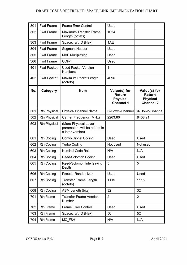
This Annex provides an example of the Space Link Implementation Chart using a virtualmission called Godzilla.
Table B-1: Example of Space Link Implementation Chart
No. Category Item Value
001 General Mission Name Godzilla
002 General Agency Name ISAS
003 General Version Number 1.0
004 General Date 2001-04-04
No. Category Item Value(s) forForwardPhysical
Channel 1
Value(s) forForwardPhysical
Channel 2
101 FwdPhysical
Physical Channel Name S-Up-Channel
102 FwdPhysical
Carrier Frequency (MHz) 2284.40
103 FwdPhysical
(More Physical Layerparameters will be added ina later version)
201 Fwd Coding BCH Codeblock Length 64
202 Fwd Coding BCH Decoding Mode Error-Correcting
203 Fwd Coding Maximum CLTU Length(octets)
1186
204 Fwd Coding Allowed Number of Errorsin Start Sequence
1
205 Fwd Coding Randomizer Used
206 Fwd Coding Physical Layer OperationsProcedure
PLOP-1
DRAFT CCSDS REFERENCE: SPACE LINK IMPLEMENTATION CHART
CCSDS xxx.x-P-0.1 Page B-2 April 2001
301 Fwd Frame Frame Error Control Used
302 Fwd Frame Maximum Transfer FrameLength (octets)
1024
303 Fwd Frame Spacecraft ID (Hex) 1AE
304 Fwd Frame Segment Header Used
305 Fwd Frame MAP Multiplexing Used
306 Fwd Frame COP-1 Used
401 Fwd Packet Used Packet VersionNumbers
1
402 Fwd Packet Maximum Packet Length(octets)
4096
No. Category Item Value(s) forReturn
PhysicalChannel 1
Value(s) forReturn
PhysicalChannel 2
501 Rtn Physical Physical Channel Name S-Down-Channel X-Down-Channel
502 Rtn Physical Carrier Frequency (MHz) 2263.60 8408.21
503 Rtn Physical (More Physical Layerparameters will be added ina later version)
601 Rtn Coding Convolutional Coding Used Used
602 Rtn Coding Turbo Coding Not used Not used
603 Rtn Coding Nominal Code Rate N/A N/A
604 Rtn Coding Reed-Solomon Coding Used Used
605 Rtn Coding Reed-Solomon InterleavingDepth
5 5
606 Rtn Coding Pseudo-Randomizer Used Used
607 Rtn Coding Transfer Frame Length(octets)
1115 1115
608 Rtn Coding ASM Length (bits) 32 32
701 Rtn Frame Transfer Frame VersionNumber
2 2
702 Rtn Frame Frame Error Control Used Used
703 Rtn Frame Spacecraft ID (Hex) 5C 5C
704 Rtn Frame MC_FSH N/A N/A
DRAFT CCSDS REFERENCE: SPACE LINK IMPLEMENTATION CHART
CCSDS xxx.x-P-0.1 Page B-3 April 2001
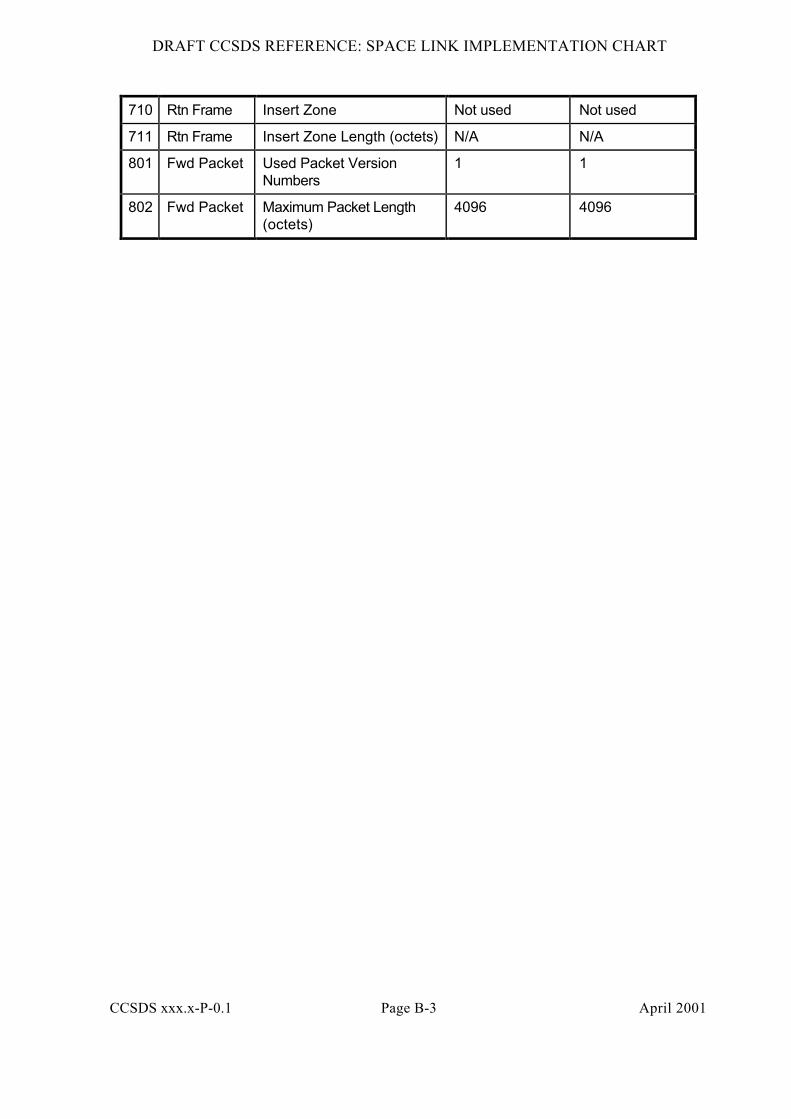
710 Rtn Frame Insert Zone Not used Not used
711 Rtn Frame Insert Zone Length (octets) N/A N/A
801 Fwd Packet Used Packet VersionNumbers
1 1
802 Fwd Packet Maximum Packet Length(octets)
4096 4096