Ongoing Nanosat Launch Vehicle Development for Providing ...

Space Environmental
NanoSat Experiment (SENSE)
Capt Paul La Tour SENSE PM

2 2
Overview
• Objectives, Organizations, and CONOPS • Spacecraft Bus • CTECS (Compact Total Electron Content Sensor) • WINCS (Wind Ion Neutrals Composition Suite) • CTIP (Compact Tiny Ionospheric Photometer) • Interesting Mission Features
3 3
Space Environmental NanoSat Experiment (SENSE)
3 Micro-Dosimeter
Tiny Photometer
Wind and Ion Drift Sensor
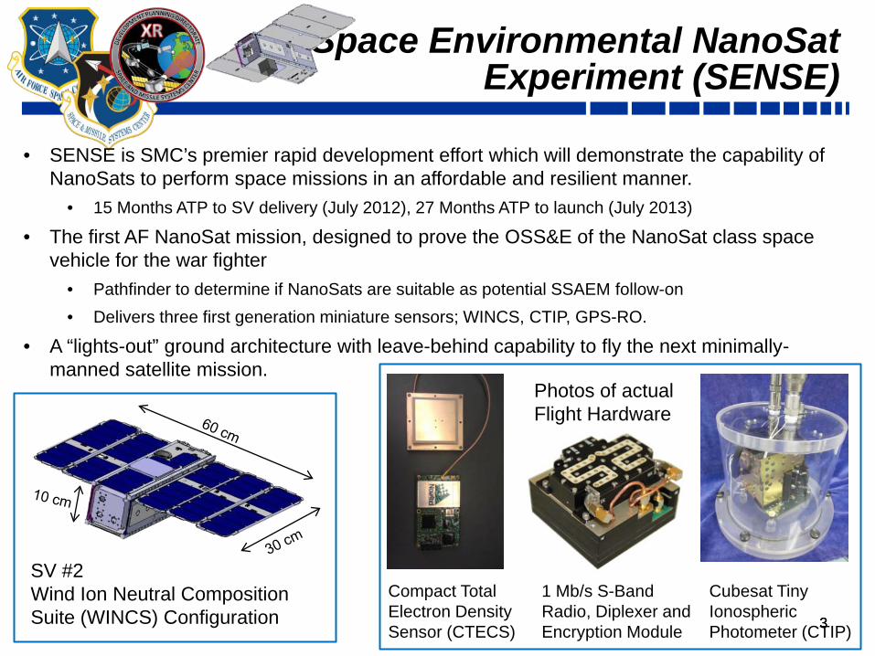
Cubesat Tiny Ionospheric Photometer (CTIP)
Photos of actual Flight Hardware
1 Mb/s S-Band Radio, Diplexer and Encryption Module
Compact Total Electron Density Sensor (CTECS)
• SENSE is SMC’s premier rapid development effort which will demonstrate the capability of NanoSats to perform space missions in an affordable and resilient manner.
• 15 Months ATP to SV delivery (July 2012), 27 Months ATP to launch (July 2013)
• The first AF NanoSat mission, designed to prove the OSS&E of the NanoSat class space vehicle for the war fighter
• Pathfinder to determine if NanoSats are suitable as potential SSAEM follow-on • Delivers three first generation miniature sensors; WINCS, CTIP, GPS-RO.
• A “lights-out” ground architecture with leave-behind capability to fly the next minimally-manned satellite mission.
SV #2 Wind Ion Neutral Composition Suite (WINCS) Configuration

4 4
400 Kg
4 Kg
2006 2008 2010 2012
CORISS
SENSE
C/NOFS
CTECS
170 Kg
FORMO-SAT3
COSMIC
CTIP
SENSE Sensor History (Evolution)
3 kg 10 Watts
0.2 kg 1.5 Watts
<1 kg 2.5 Watts
7 kg 23 Watts
Smaller Satellites
Bigger Roles

5
TRR DR IDR Launch Award
Schedule
Space Segment (XR)
Data Analysis Segment (AFRL)
Ground Segment (SDTW)
Key Milestones
FY10 FY11 FY12 FY13 1 2 3 4 1 2 3 4 1 2 3 4 1 2 3 4
Launch Segment (SDTW)
PSR Final Report
Ground Study
Launch Integration
Est Jun13
RFP Development
Source Selection
Sensor Development
Bus Assembly & Test
On Orbit Support
Antenna Acquisition
Develop Ground Infrastructure
IA Certification
OPS Support
Launch Coordination
Launch Integration
Technical Support Hardware/Software Prep Data Analysis & Validation
Interface with AFRL
Common Ground Architecture
ORS Enabler
Multi-Segment Critical Path- Factory Compatibility Test
Critical Path– Flight Software
Critical Path– CGA Software
Critical Path– Pre-Processing Software
15 Months
$1.700M $6.137M $1.782M $.899M
This is Rapid!

6 6
SENSE Organizations
Space Segment (XRFF)
Demo Stakeholder
Ground Segment (SDTO)
Data Analysis & Mission Validation (RVBX)
Launch Segment (SDTD)
SENSE Demo Lead Demo Stakeholder
DWSD SMC

7 7
GPS
L1 & L2 Signal
Strength Raw
Neutral Wind & Ion
Temperature
Ion and Neutral
Composition Up to 200amu
Neutral Wind Vector
UV Photons Oxygen 135.6nm
GPS L1 & L2 Signal
Strength Raw Pseudo-Range and Phase Data
SRI
Aerospace AFRL
NRL
Boeing Measurements
Physical Interfaces
Spacecraft B
WINCS
Bus Data
GPS RO Sensor
GPS RO Sensor
Bus Data CTIP
Spacecraft A
Spac
e/G
roun
d IC
D (S
D/N
RL/
BOEI
NG
_SPE
C_I
CD
_01)
RS
C
Dat
a Le
vel 0
– S
ENSE
Spa
ce to
Veh
icle
GPP
Common Ground
Architecture (CGA)
Kirtland RSC
Ground Stations and relays
S-Band Uplinks and Downlinks
SMC/SD
Military Users (AFWA), Science
Teams, and Boeing Innoflight
Radio
Radio
Ionispheric Prediction Models
(GAIM ) Data Level 3
Ground Pre-Processing
AFRL Data Processing
Ionospheric Models; GAIM (Utah State, JPL) and
prototypes
Data Level 3—GAIM Outputs
Data Level 2 Environmental Data Record ICD
SENSE Data Flow and Partner Organizations
Organizations

8
Ground Segment
Contribution to Greater Capability: •Demonstrate a distributed architecture to support small satellite missions including “lights-out” (unmanned) operations
• Established conductivity between Air Force mission operation center, Navy communications, and joint service command network
• Define architecture for pre-processing of data and automatic distribution
• Develop ground architecture with “leave behind” capability for future CubeSat programs
• Operations Center improvements enabling flexible, distributed architectures
• Platform for operator training
Future Improvements: • Automated satellite command and control
• CubeSats offer potential for inexpensive distributed data collection through greater automation
• Increase contact frequency of CubeSats on operational networks proves operational theories
• Drive development of side-by-side operations with larger satellites on same contact network • Peacetime means of maintaining operator proficiency
BACKGROUND: • Current satellite C2 systems utilize 24/7
ground monitoring; SENSE striving for “lights out” capability
• Kirtland RSC Operations Center developing capability to connect to distributed sites from single terminal
• FY 2013-14 SENSE demonstration period with option to extend ops 1-year
CTIP
WINCS-WTS-IMS-NMS
neutral wind vector
neutral wind vectorand temp
GPSReceiver
GPSL1 & L2
Signal strength(raw pseudo-range
and phase data)
Iontemperature
Ion and neutral composition
Up to 200 amu
Bus
Bus
Relay/GroundStations
MissionOps
SENSEGrdPre-
ProcessingSoftware
Ionosphericpredictionmodels,(GAIM,PBMod)
GPSReceiver
Spacecraft A
Spacecraft B
GPSL1 & L2
Signal strength(raw pseudo-range
and phase data)
• Sensors (CTP, WINCS) raw data are converted into ionosphericscientific data record (SDR)
•SDRs are converted into ionospheric environmental data records (EDRs).
•Convert the GPS raw pseudo-range and phase data toestimate TEC, amplitude and phase scintillation indexes
UV Photons(oxygen 135.6 nm )
KeyMeasurements
SENSEElements
GroundElements
S-BandDwnLink
S-BandDwnLink

9 9
SEM Matrix
10 10
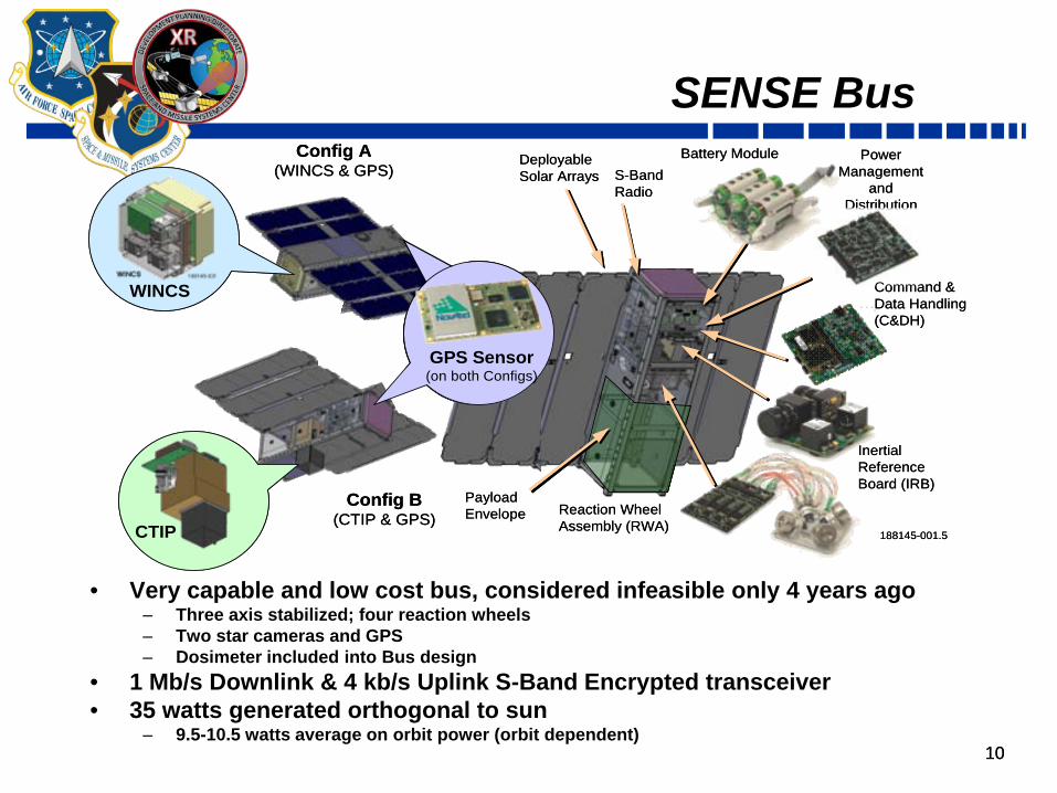
SENSE Bus
• Very capable and low cost bus, considered infeasible only 4 years ago ‒ Three axis stabilized; four reaction wheels ‒ Two star cameras and GPS ‒ Dosimeter included into Bus design
• 1 Mb/s Downlink & 4 kb/s Uplink S-Band Encrypted transceiver • 35 watts generated orthogonal to sun
‒ 9.5-10.5 watts average on orbit power (orbit dependent)
188145-001.5
Inertial Reference Board (IRB)
Config A (WINCS & GPS)
Config B(CTIP & GPS)
WINCS
Reaction Wheel Assembly (RWA)
Power Management
and Distribution
(PMAD)
Battery Module
Payload Envelope
Deployable Solar Arrays S-Band
Radio
CTIP
GPS Sensor(on both Configs)
WINCS Command & Data Handling (C&DH)

11
3.4
3.5
3.6
3.7
3.8
3.9
4
4.1
4.2
4.3
26-Feb-11 17-Apr-11 6-Jun-11 26-Jul-11 14-Sep-11 3-Nov-11 23-Dec-11 11-Feb-12 1-Apr-12
Mas
s (K
g) With Margin
No Margin
Launch Requirement
Space Vehicle Mass (Worst Case SV #2)
11
12
Positive Energy Balance
12
Ref Orbit 600km 45 deg Inclination Polar Orbit 600km Sun Synch 0
10
20
30
40
50
60
70
80
90
100
0.0
5.0
10.0
15.0
20.0
25.0
30.0
35.0
40.0
0:00 0:20 0:40 1:00 1:20
SOC
[%]
Pow
er [W
]
Time [h:mm]
Solar Power Actual UTJ (W) Payload load (W)
Bus load (W) Payload Capability (W)
Battery SOC (%)
Comm Events SV Payload Capability
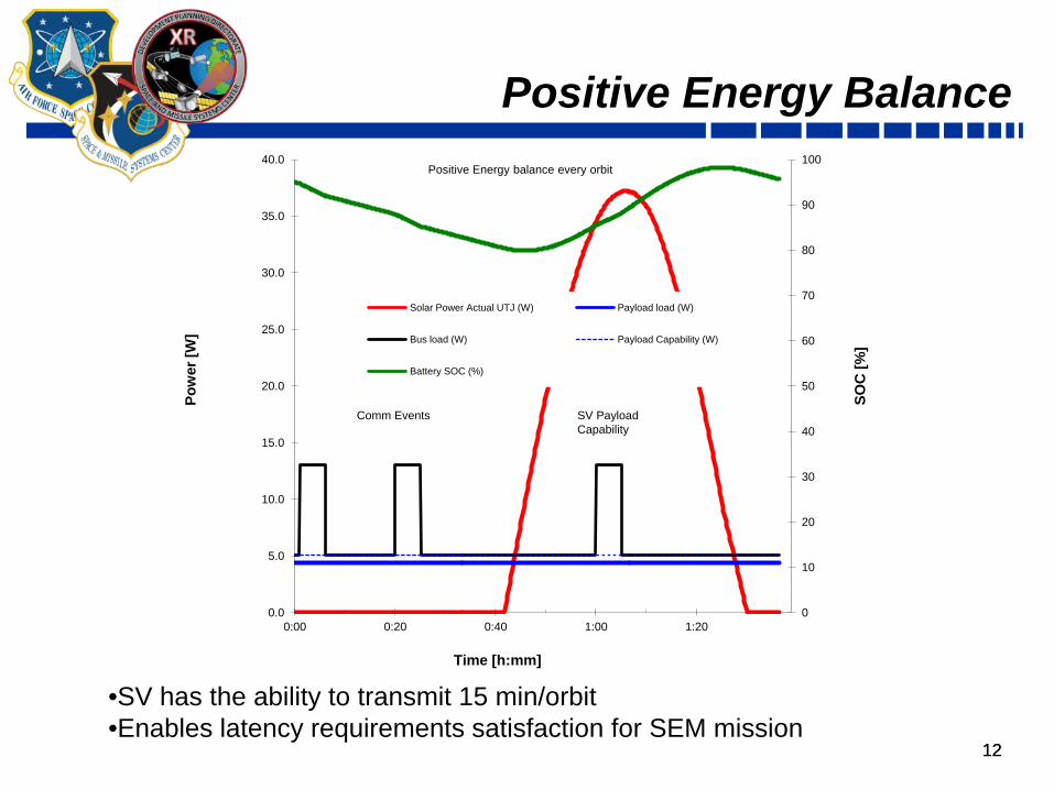
Positive Energy balance every orbit
•SV has the ability to transmit 15 min/orbit •Enables latency requirements satisfaction for SEM mission

13
• CTECS is a GPS occultation sensor ‒ Primary data product: line-of-sight TEC to all
GPS satellites in view for ingest into ionospheric models
‒ Secondary data product: L-band scintillation observations
• Antenna is dual patch ‒ 1557 MHz and 1227 MHz ‒ A Low-Noise-Amplifier (LNA) is placed between
antenna and receiver • L1, L2, L2c signal tracking capability
CTECS- Radio Occultation Sensor
NovAtel OEMV-2 receiver
AutoCad drawing of CTECS custom dual patch antenna embedded in the MTV satellite panel.
Objective: Perform Radio Occultation Measurement of GPS and gather atmospheric scintillation data
Measures: 1. Delay of signal between SENSE and the
GPS transmitter to extract Total Electron Count in the atmosphere
2. Atmospheric Scintillation 13

14 14
Compact Tiny Ionospheric Photometer (CTIP)
Measures: 1. Ultraviolet Airglow at 135.6 nm
• Atomic Oxygen ions constitute the primary ionospheric species in the F-region
• In the night-time F-region ionosphere ‒ 135.6 nm photons are emitted spontaneously ‒ from the recombination of atomic oxygen ions ‒ O+ + e- → O (5P) + hν135.6
• O+ and e- are in equal number and 135.6 nm emission is proportional to the path integral of [O+] squared
Objective: Gather data to characterize the ionosphere through the natural decay rate as seen in recombination of O+ ions and electrons

15 15
Wind Ion Neutral Composite Suite (WINCS)
Measures: 1. Neutral winds & temperature 2. Ion-drift & temperature 3. Ion & Neutral composition 4. Plasma Composition
Objective: Acquire simultaneous co-located, in-situ measurements of atmospheric density, composition, temperature and winds.
15
Focal Plane Array Sensor
Electronics
Anodes and HV Power Supply
WTS/IDTS
16 16
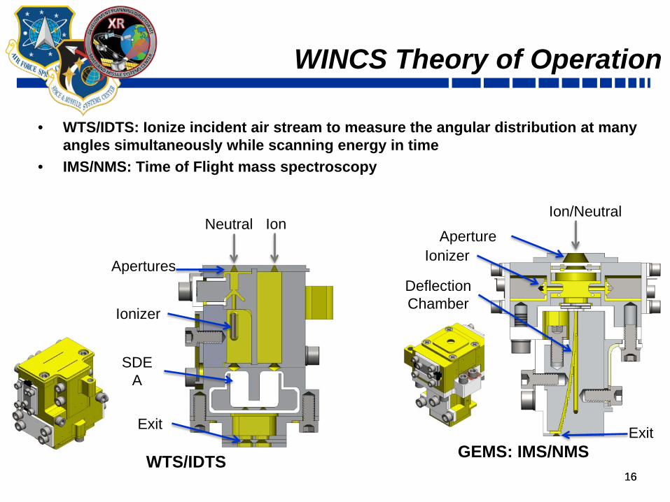
WINCS Theory of Operation
• WTS/IDTS: Ionize incident air stream to measure the angular distribution at many angles simultaneously while scanning energy in time
• IMS/NMS: Time of Flight mass spectroscopy
SDEA
Ionizer
Apertures
Exit
Neutral Ion
WTS/IDTS
Deflection Chamber
Ionizer Aperture
Exit
Ion/Neutral
GEMS: IMS/NMS
17 17
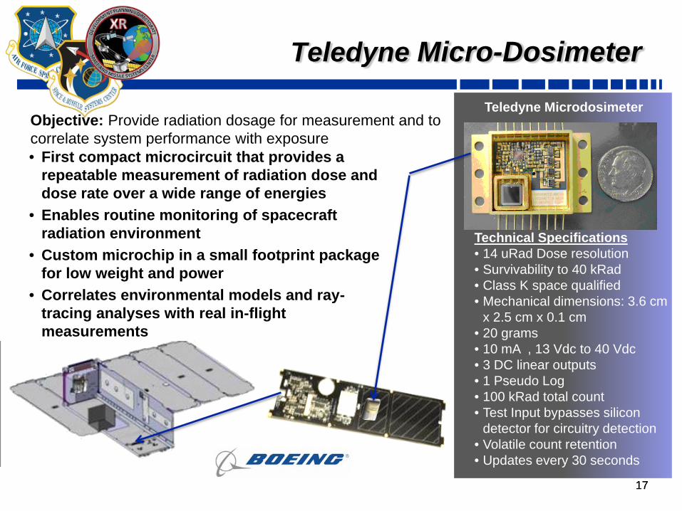
Measures: 1. Radiation over time
Teledyne Micro-Dosimeter
• First compact microcircuit that provides a repeatable measurement of radiation dose and dose rate over a wide range of energies
• Enables routine monitoring of spacecraft radiation environment
• Custom microchip in a small footprint package for low weight and power
• Correlates environmental models and ray-tracing analyses with real in-flight measurements
Technical Specifications • 14 uRad Dose resolution • Survivability to 40 kRad • Class K space qualified • Mechanical dimensions: 3.6 cm
x 2.5 cm x 0.1 cm • 20 grams • 10 mA , 13 Vdc to 40 Vdc • 3 DC linear outputs • 1 Pseudo Log • 100 kRad total count • Test Input bypasses silicon
detector for circuitry detection • Volatile count retention • Updates every 30 seconds
-X Side Panel
Teledyne Microdosimeter Objective: Provide radiation dosage for measurement and to correlate system performance with exposure

18 18
Mission Data Products (TPMs)
Threshold Objective CTECS WINCS CTIP SENSEElectron density profile Horizontal cell size 50 km 10 km Variable 8 km 15 km 8 kmElectron density profile Vert Cell Size 10 km 3 km 6 km N/A 10 km 2 kmElectron density profile Vert coverage 90 km to Sat Alt 90 km to 1600 km 90 km to Sat Alt N/A 90 km to Sat Alt 90 km to Sat AltElectron density profile Range Ne 2.5E4 to 1E7 e/cm3 1E4 to 1E7 e/cm3 2E4 to 1E7 e/cm3 1E3 – 1E7/cm3 2E4 to 1.4E8 1E4 to 1E7 e/cm3
Electron density profile Range VTEC 3 to 200 TECU 1 to 200 TECU 3 to 200 TECU N/A 3 to 19000 TECU 1 to 19000 TECU
Electron density profile Sigma NeGreater of 1E5 /cm3 or 30%
Greater of 1E4 /cm3
or 5% Variable1 10% ± 9% < 20%
Electron density profile Sigma TECGreater of 3 TECU
or 30%Greater of 1 TECU
or 30%Greater of 3 TECU
or 35% N/A 3 TECUGreater of 1 TECU
or 20%
Electron density profile Sigma HmF2 20 km 5 km 20 km N/A N/A 10 km
Electron density profile Sigma NmF2 20% 10% 30% N/A N/A 15%
Electron density profile Sigma NmE 20% 5% 100% N/A N/A 20%Electron density profile Latency 90 minutes 15 mintues 15 mintues N/A 15 minutes 15 mintues
Scintillation Horizontal Cell Size 100 km 25 km 500-2000 km N/A N/A 15 kmScintillation Amp. index (S4) 0.1 to 0.5 0.1 to 1.5 0.1 to 1.5 N/A N/A 0.1 to 1.5Scintillation Phase Index (σϕ) 0.1 to 20 rad 0.1 to 20 rad 0.1 to 20 rad N/A N/A 0.1 to 20 radScintillation Uncertainty S4 0.1 0.1 0.1 N/A N/A 0.1Scintillation Uncertainty σϕ 0.1 rad 0.1 rad 0.1 rad N/A N/A 0.1 radScintillation Latency 90 minutes 15 mintues 15 mintues N/A N/A 15 mintues
Ions Ion species none O2+, NO+, O+, H+, He+ N/A O2
+, NO+, O+, H+, He+ N/A O2+, NO+, O+, H+, He+
IonsComposition
discrimination none 5% of Ne N/A 5 % of Ne N/A 5% of NeIons Drift velocity none Objective N/A +/- 2000 m/s N/A +/- 2000 m/sIons Density none Objective N/A 1E3 – 1E7/cm3 N/A 1E3 – 1E7/cm3
Ions Density fluctuations none Objective N/A 1E3 – 1E7/cm3 N/A 1E3 – 1E7/cm3
Ions Energy none Objective N/A 0 to 20 ev N/A 0 to 20 evIons Temperature none Objective N/A 1000 K to 4000 K N/A 1000 K to 4000 K
Electric Field Electric field none Objective N/A 0 to 150 mV/m N/A 0 to 150 mV/mNeutrals Wind speed none Objective N/A +/- 2000 m/s N/A +/- 2000 m/sNeutrals Density none Objective N/A 1E3 to 1E10 /cm3 N/A 1E3 to 1E10 /cm3
Neutrals Temperature none Objective N/A 1000 K to 4000 K N/A 1000 K to 4000 K1. 100% E layer, 50% F layer bottom side, 30% F layer near peak, 15% topside
Environmental Data Record (EDR) Parameter
Requirements Current Value at DR

19
Reliability Modeling (CTIP)
19
• CTIP vehicle reliability is estimated to be 0.7312 at 1 year.
• 5 Bus Drivers are: • USB Radio (0.950) • IRB (0.954) • PMAD (0.969) • RWA controller (0.975) • +Y Body panel (0.980)
• Payload Driver • CTIP (0.960)
0.350.400.450.500.550.600.650.700.750.800.850.900.951.00
0 0.25 0.5 0.75 1 1.25 1.5 1.75 2 2.25 2.5 2.75 3
Rel
iabi
lity
Mission (Years)
SENSE CTIP RELIABILITY PREDICTION

20
Summary
• SENSE is a rapid development effort seeking to demonstrate affordable access to space for future operational CubeSat missions across SMC • Develop best practices for operational CubeSat/NanoSat procurement,
development, test, and operations • The first CubeSat mission to develop a flexible, distributed ground
architecture supporting small satellite missions • Two one-month ops phases consisting of 24/7 operations using commercial and
distributed joint service command antennae network for <90 minute data latency • Mature CubeSat Bus and Sensor component TRLs
• CubeSats drives down future costs for inexpensive distributed data collection systems through a common CubeSat Bus ($300K per bus)
• The common Bus becomes a platform for both operational use and future sensor development efforts
• Three first generation miniature sensors; WINCS, CTIP, GPS-RO • Mission data will improve current and future space weather models and
demonstrate CubeSats’ utility for operational weather requirements 20