Space and Geographical Operational Robot
8
ISSN: 2395 -0560 Int ernat iona l R esea rch J ourna l of Innova t ive Engi neering www.irjie.com Volume1 , I ssue 3 of March 20 1 5 © 20 15 ,I RJ I E-Al l Ri ghts Reserved Page -67 Space and Geographical Operational Robot Jackson Alex 1 , Sanket Gaikwad 2 , Shital Shelar 3 ,Prof. T. S. Reddy 4 Prof. S. N. Longani 5 BE Electronics & Telecommun ications, IS B&M Scho ol of Techno logy, Pun e-42. Departme nt of Electron ics & Telecommunication s, ISB& M School o f Technolog y, Pune-42 . Abstract - It is difficult for humans to record atmospheric conditions and to collect specimens needed for research at places where human cannot survive or reach. Most of existing robots are used to carry out only one application at a time. Thus proposing a system that can overcome above said problems. This space operational robot consist of numerous sensors around itself so as to sense the environment in which it is set up, the designing of this robot is made in such a way that it could survive tremendous bad weather as it has to be operated in the unknown atmosphere. It has wide applications even on the earth, and it can be used for studying different geological surfaces and many areas where human cannot reach. It is composed of such features w hich will help scientists a lo t in their rese arch wo rks. It has robotic arm i nbuilt on it so as to collect specimen which is suspected and it also has wireless-camera which keeps giving the live feedback to the user, the bunch of sensors are also composed to sense the residing environme nt for example t o find water, human, bomb detection and diffusion, temperature change etc. The most highlighting feature of this robot is the detachable sensors. So, this r obot is more compatible and useful for multi-purpose operations. All these features are combined in such a way that makes this device applicable in many conditions. Keywords - R obotic arm, D.C motor, sensors, 16F877A PIC microcontrolle r. 1. Introduction: In recent years, the social aspect of service robots has made it clear that these are not only expected to navigate within the environment they have been placed in but they also have to interact with the people to provide useful services and show good communication skills. It is diff icult for h umans to record atmospheric conditions and to collect specimens needed for research at places where human cannot su rvive or reach. O ne of the mo st important problems f aced by robots to day is that many of them are used for one or two application at a time. Also we have different robots for space and earth separately , that is the robots used for space works cannot be used for applications on earth. Thus, going through all this drawbacks we came up with the idea of making a robot with detachable sensors that can be used for both space and geographical applications. With the help of detachable sensors we can use different sensors [1] at a time such as temperature sensor, human detection sensor, bomb detection and diffusion, chemical detection sensors etc This can be replaced with the other ones depending upon the need of application. Moreover, this robot is also installed with robotic arm [2] in order to pick and drop the object, problem arises when it has to pick up thin objects like paper or a sheet, and thus it is provided with the nails so as to overcome this problem. It also has wireless-camera which keeps giving the live feedback to the user, this can be used to navigate the robot properly and get the live feedback all the time. One of the other features provided with this robot is the solar panels [3]. This is used for providing backup to the battery. This feature is very important as it is not possible for the humans to change the battery every time, thus the solar panels will provide backup and thus the robot can work more effe ctively. As this robot has to be used on rough terrains, large wheels with high torque are used so as to get more power. The wheels are provided with the 4x4 mechanism that is each wheel is provided with separate motors. The motor used are D.C motors.
description
It is difficult for humans to record atmospheric conditions and to collect specimens needed for research atplaces where human cannot survive or reach. Most of existing robots are used to carry out only one application at a time.Thus proposing a system that can overcome above said problems. This space operational robot consist of numerous sensorsaround itself so as to sense the environment in which it is set up, the designing of this robot is made in such a way that itcould survive tremendous bad weather as it has to be operated in the unknown atmosphere. It has wide applications even onthe earth, and it can be used for studying different geological surfaces and many areas where human cannot reach. It iscomposed of such features which will help scientists a lot in their research works. It has robotic arm inbuilt on it so as tocollect specimen which is suspected and it also has wireless-camera which keeps giving the live feedback to the user, thebunch of sensors are also composed to sense the residing environment for example to find water, human, bomb detectionand diffusion, temperature change etc. The most highlighting feature of this robot is the detachable sensors. So, this robot ismore compatible and useful for multi-purpose operations. All these features are combined in such a way that makes thisdevice applicable in many conditions.
Transcript of Space and Geographical Operational Robot

7/18/2019 Space and Geographical Operational Robot
http://slidepdf.com/reader/full/space-and-geographical-operational-robot 1/8
ISSN: 2395-0560
International Research Journal of Innovative Engineeringwww.irjie.com
Volume1, Issue 3 of March 2015
_____________________________________________________________________________________________________________©2015 ,IRJIE-All Rights Reserved Page -67
Space and Geographical Operational Robot
Jackson Alex1, Sanket Gaikwad
2, Shital Shelar
3,Prof. T. S. Reddy
4 Prof. S. N. Longani
5
BE Electronics & Telecommunications, ISB&M School of Technology, Pune-42.
Department of Electronics & Telecommunications, ISB&M School of Technology, Pune-42.
Abstract - It is difficult for humans to record atmospheric conditions and to collect specimens needed for research at
places where human cannot survive or reach. Most of existing robots are used to carry out only one application at a time.
Thus proposing a system that can overcome above said problems. This space operational robot consist of numerous sensorsaround itself so as to sense the environment in which it is set up, the designing of this robot is made in such a way that it
could survive tremendous bad weather as it has to be operated in the unknown atmosphere. It has wide applications even on
the earth, and it can be used for studying different geological surfaces and many areas where human cannot reach. It is
composed of such features which will help scientists a lot in their research works. It has robotic arm inbuilt on it so as to
collect specimen which is suspected and it also has wireless-camera which keeps giving the live feedback to the user, the
bunch of sensors are also composed to sense the residing environment for example to find water, human, bomb detection
and diffusion, temperature change etc. The most highlighting feature of this robot is the detachable sensors. So, this robot is
more compatible and useful for multi-purpose operations. All these features are combined in such a way that makes this
device applicable in many conditions.
Keywords - R obotic arm, D.C motor, sensors, 16F877A PIC microcontroller.
1. Introduction:
In recent years, the social aspect of service robots has made it clear that these are not only expected to navigate within
the environment they have been placed in but they also have to interact with the people to provide useful services and show
good communication skills. It is difficult for humans to record atmospheric conditions and to collect specimens needed for
research at places where human cannot survive or reach. One of the most important problems faced by robots today is that
many of them are used for one or two application at a time.
Also we have different robots for space and earth separately, that is the robots used for space works cannot be used for
applications on earth.
Thus, going through all this drawbacks we came up with the idea of making a robot with detachable sensors that can
be used for both space and geographical applications. With the help of detachable sensors we can use different sensors [1]at a time such as temperature sensor, human detection sensor, bomb detection and diffusion, chemical detection sensors etc
This can be replaced with the other ones depending upon the need of application. Moreover, this robot is also installed with
robotic arm [2] in order to pick and drop the object, problem arises when it has to pick up thin objects like paper or a sheet,
and thus it is provided with the nails so as to overcome this problem. It also has wireless-camera which keeps giving the
live feedback to the user, this can be used to navigate the robot properly and get the live feedback all the time. One of the
other features provided with this robot is the solar panels [3]. This is used for providing backup to the battery. This feature
is very important as it is not possible for the humans to change the battery every time, thus the solar panels will provide
backup and thus the robot can work more effectively. As this robot has to be used on rough terrains, large wheels with high
torque are used so as to get more power. The wheels are provided with the 4x4 mechanism that is each wheel is provided
with separate motors. The motor used are D.C motors.
7/18/2019 Space and Geographical Operational Robot
http://slidepdf.com/reader/full/space-and-geographical-operational-robot 2/8
ISSN: 2395-0560
International Research Journal of Innovative Engineeringwww.irjie.com
Volume1, Issue 3 of March 2015
_____________________________________________________________________________________________________________©2015 ,IRJIE-All Rights Reserved Page -68
Thus it is possible to use this service robot in both research and military operations provided that it has to undergo
some changes. The changes to be done will not be drastic; the basic design will be the same, only the programming neededfor different operations need to be updated.
All these features are combined in this project so that it can be used for both space and geographical applications un-
der the same basic design effectively.
Different space and geological organizations including NASA, ISRO and National geological department of India can
be benefited with the introduction of this kind of multi-purpose service robot.
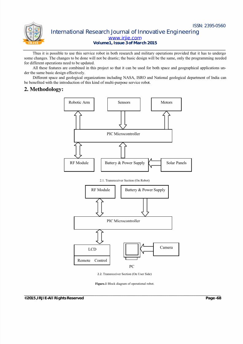
2. Methodology:
2.1. Transreceiver Section (On Robot)
2.2. Transreceiver Section (On User Side)
Figure.1 Block diagram of operational robot.
Robotic Arm Sensors Motors
RF Module
PIC Microcontroller
Battery & Power Supply Solar Panels
RF Module Battery & Power Supply
PIC Microcontroller
LCD
Remote Control
Camera
PC
7/18/2019 Space and Geographical Operational Robot
http://slidepdf.com/reader/full/space-and-geographical-operational-robot 3/8
ISSN: 2395-0560
International Research Journal of Innovative Engineeringwww.irjie.com
Volume1, Issue 3 of March 2015
_____________________________________________________________________________________________________________©2015 ,IRJIE-All Rights Reserved Page -69
The robot will move according to the direction given by the user through remote control. Now, the PIC Microcontrol-
ler gives the signal to the RF module which transfers the signal to the other RF module situated on the Transreceiver sec-tion on the robot. The RF module on the robot forwards the signal to the PIC microcontroller and the motor on the wheels
starts. The same working principle is carried out for the motors on the robotic arm to perform its motion. The sensors
placed on the robot sense the respective environmental conditions and passes on the signals to the PIC Microcontroller. The
RF Module on the Transreceiver section on the robot transfers the signals from the PIC Microcontroller to the other RF
Module on the Transreceiver section on the user side. Now, the PIC Microcontroller on the robot takes the takes from the
RF Module and forwards it to the LCD Display so as to show the output of the sensors. The current from the solar panel
placed on the robot is given to the battery which provides backup to the battery on the robot.
16F877A PIC MICROCONTROLLER:-
Peripheral Features:
It has three timers namely, Timer0: 8-bit timer/counter with prescaler of 8-bit, Timer1: 16-bit counter/timer with prescaler,
and Timer2: 8-bit counter/timer of 8-bit, prescaler and postscaler, two Capture, Compare, PWM modules where it hascapture of 16-bit.
Analog Features:
It has 10-bit, up to 8-channel Analog-to-Digital Converter (A/D). It also has analog Comparator module with two analog
comparators, on-chip programmable voltage reference module, input programmable multiplexing from device inputs and
internal voltage reference.
Program Memory Organization:
The PIC16F87XA devices have a program counter of 13bit which has addressing of 14 bit program memory space x 8K
word. The PIC16F877A devices have 14 bits of Flash program memory x 8K words, while PIC16F8774A devices have 14
bits x 4K words. Wrap round is caused due to access of location which is above the physically implemented address.
Data Memory Organization:
The data memory consists of multiple banks which contain the SFR that is Special Function Registers and the General
Purpose Registers. Bits RP1 with Status<6> and RP0 with Status<5> are the bank select bits. The Special Function
Registers (SFR’s) has its reservation at the lower locations of each bank.
ROBOTIC ARM:-
The DOF, or the Degree Of Freedom is the most important concept to understand in terms of robotic arm. Each degree
of freedom is a place where it can bend, translate or rotate, or else we can say a joint on the arm. By the total number of
actuators on the robotic arm, the number of degrees of freedom can be typically identified. Now the important point is that
when making a robot arm we want few degrees of freedom (DOF) for our application because each degree requires a motor,
sometimes an encoder, and complicated algorithms and also the cost. Drawing robot arms in free body diagrams has themethod of Denavit-Hartenberg convention. A joint could be made by only two motions: rotate and translate. This could
happen on only three: x, y, and z (out of plane).

7/18/2019 Space and Geographical Operational Robot
http://slidepdf.com/reader/full/space-and-geographical-operational-robot 4/8
ISSN: 2395-0560
International Research Journal of Innovative Engineeringwww.irjie.com
Volume1, Issue 3 of March 2015
_____________________________________________________________________________________________________________©2015 ,IRJIE-All Rights Reserved Page -70
Figure.2 DOF of robotic arm.
Notice that there is a linkage between each DOF which is of particular length. Sometimes multiple DOF can be
found on a joint in the same location. The most popular example is the shoulder. The human shoulder has three coincident
DOF.
Figure.3 DOF representation of human shoulder.
A limitation of DOF is known as the configuration space. All joints cannot swivel in 360 degrees. A joint has some
maximum angle restriction. For example, human joint cannot rotate more than about 200 degrees. The limitations could be
varied from wire wrapping, servo maximum angle, actuator capabilities, etc. It is possible to label each link length and joint
maximum angle on the FBD.
Robot Workspace:
The reachable or the robot workspace is all places that the gripper or end effector can reach. The workspace depends
on the DOF translation or angle limitations, the angle, the arm lengths, links, etc. A moving robot consisting of a robot
arm is also termed as a sub-class of robotic arms and they work just like other robotic arms. If say a robot arm (5 DOF)
having a differential drive robot (2 DOF) (see robot below), which gives a total of 7 DOF.

7/18/2019 Space and Geographical Operational Robot
http://slidepdf.com/reader/full/space-and-geographical-operational-robot 5/8
ISSN: 2395-0560
International Research Journal of Innovative Engineeringwww.irjie.com
Volume1, Issue 3 of March 2015
_____________________________________________________________________________________________________________©2015 ,IRJIE-All Rights Reserved Page -71
Figure.4. Robotic arm on moving robot.
D.C MOTOR:-
To know the operating principle of DC motor, it’s important to have a basic understanding and knowledge of
Fleming’s Left hand rule which determine the direction of force on the conductors of permanent dc motor. It says that if we
extend the thumb, middle finger and index finger of our left hand in a position that the index finger indicates the electric
current carrying conductor placed in a magnetic field which is perpendicular to the middle finger indicating the direction
of electric current, then the thumb indicating conductor which experiences a force in the direction of the mutually
perpendicular direction of field and the electric current in the conductor. Today’s field of technology has lot of applications
based on DC motor. Even a shaver has DC motor in it. DC motors is more useful in motoring applications.The DC motor types can be listed as follows: DC motor, permanent magnet DC motor, separately excited DC motor,
self-excited DC motor, compound wound DC motor, cumulative compound DC motor, differential compound DC motor.
We are using the permanent magnet DC motor. Permanent magnet is used to make the field poles of permanent magnet DC
motor. A PMDC motor consists of two parts – a armature and stator. The stator is basically a steel cylinder. The inner
periphery of this cylinder is attached with magnets. The permanent magnets are mounted such that the S - pole and N- pole
of each magnet are faced on the same side of armature alternatively as shown in the figure. That means, if S - pole of one
magnet is faced on the same side of armature then N - pole of the next magnet should be faced towards armature. The steel
cylindrical stator provides return path with low reluctance for the magnetic flux. It is sometimes found that field coil is used
along with permanent magnet.
Figure.5. Stator of permanent magnet DC motor.
7/18/2019 Space and Geographical Operational Robot
http://slidepdf.com/reader/full/space-and-geographical-operational-robot 6/8
ISSN: 2395-0560
International Research Journal of Innovative Engineeringwww.irjie.com
Volume1, Issue 3 of March 2015
_____________________________________________________________________________________________________________©2015 ,IRJIE-All Rights Reserved Page -72
Working principle of PMDC motor is almost same as that of DC motor. The conductor experiences force when a
carrying conductor comes into a magnetic field and the direction of this force is given by Fleming’s left hand rule. In a permanent magnet dc motor, the magnetic field of permanent magnet consists of the armature. Now here each conductor of
the armature goes through the force (F) = Magnetic field strength in Tesla (B)*Electric current in Ampere(I)*Length in
meter(L). The compilation of forces produces a torque as force is experienced by each conductor, which tends to rotate the
armature. Hence voltage equation of the motor is given as,
V= I*R + E b
Where I is armature electric current and R is armature resistance of motor, E b is the back electromagnetic field and V is the
voltage supply.
SOLAR PANEL:-
The most important concept is the sunlight. Sunlight is totally composed of energy which is photons that is photons
have different energies. When we look at a rainbow, we see different colors; where in these colors each colors represents a
photons with a different energy level. The photon frees one electron from the atom when one of them strikes an atom in a
photo voltaic (PV) cell. The electron which got freed begins to wander around the PV cell, which finally comes into contact
with a metal wire to the opposite side of the PV cell. The rest of the electron continues its movement through the wire. Things
that need electricity like a computer, light bulb, batteries or refrigerators is connected by wire. There are chances that the
electricity we are now using might have started from a free electron created by a photon from the sun.
If we look on the atomic level of phosphorous, we see that phosphorous has three shells. But, we’re only interested in the
last shell. So in phosphorous, the last shell has 5 electrons. Boron has 2 shells and has 3 electrons in its last shell. Silicon
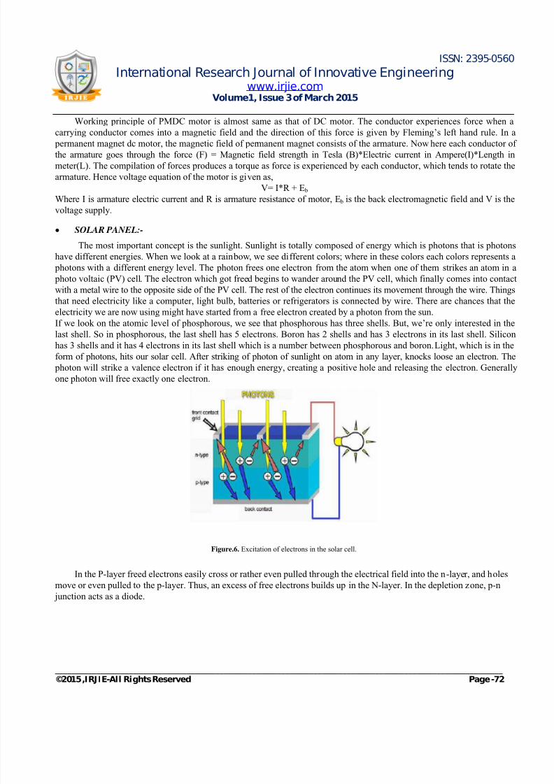
has 3 shells and it has 4 electrons in its last shell which is a number between phosphorous and boron. Light, which is in the
form of photons, hits our solar cell. After striking of photon of sunlight on atom in any layer, knocks loose an electron. The
photon will strike a valence electron if it has enough energy, creating a positive hole and releasing the electron. Generally
one photon will free exactly one electron.
Figure.6. Excitation of electrons in the solar cell.
In the P-layer freed electrons easily cross or rather even pulled through the electrical field into the n-layer, and holes
move or even pulled to the p-layer. Thus, an excess of free electrons builds up in the N-layer. In the depletion zone, p-n
junction acts as a diode.

7/18/2019 Space and Geographical Operational Robot
http://slidepdf.com/reader/full/space-and-geographical-operational-robot 7/8
ISSN: 2395-0560
International Research Journal of Innovative Engineeringwww.irjie.com
Volume1, Issue 3 of March 2015
_____________________________________________________________________________________________________________©2015 ,IRJIE-All Rights Reserved Page -73
Figure.7. Formation of depletion zone.
The imbalance which is also known as electrical imbalance at the depleted zone or junction is about 0.6 to 0.7 volts. A
in-built electric field is formed or present across the solar cell due to the p-n junction. You could also say that how muchelectricity you’ll get from your PV cell. If the voltage is known, you can calculate the energy of all the photons, from the
sun, striking your PV cell with 0.6 to 0.7 volts to knock an electron lose; that will give you the theoretical efficiency of a
PV cell. The formula to find the approximate electricity generated in photovoltaic system is:
E = A * r * H * PR
E = Energy (kWh)
A = Area of Solar panel (m²)
r = Solar panel yield (%)
H = Average solar radiation on panels
PR = Performance ratio
3. Result:We have taken the number of testing around with the RF communication and motion of motors. The problem we
faced was with the motors. The speed of the motors was not able to generate the required amount of torque to move the
entire robot as it was bit heavy. Then the changes were done to increase the speed of the motors effectively to generate
required amount of torque to carry the basic weight of the robot including weight of the solar panels.
Table 1: Result table to describe relation between the sensors, Input voltage and output voltage
Table 2: Result table to describe the range of RF module and camera
Sensors Input Voltage Output Voltage
PIR Sensor 5V 0V; 3.5V
Water Sensor 5V 0V;5V
Proximity Sensor 5V 0V;5V
Equipment Range
RF Module 434 MHz (150m)
Camera 100m approx.

7/18/2019 Space and Geographical Operational Robot
http://slidepdf.com/reader/full/space-and-geographical-operational-robot 8/8
ISSN: 2395-0560
International Research Journal of Innovative Engineeringwww.irjie.com
Volume1, Issue 3 of March 2015
_____________________________________________________________________________________________________________©2015 ,IRJIE-All Rights Reserved Page -74
Table 3. Result table to describe the total time required to fully recharge 1.2A battery
The tables above give the comparison between the different types of solar panels with different output voltage and
power. As we can conclude from the above table that the solar panel with the output voltage of 12V and power of 10 W
charges the 1.2A battery that we are using in this project more efficiently and in less time.
Torque of each motor of the wheel = 500 Nm
Thus, total torque for 4 motors = 4 x 500 Nm = 2000 Nm
4. Conclusion
The project that we have suggested can cater for both space and geographical activities without doing much change in
the basic design. It is a multi-purpose robot with different properties like robotic arm to pick and drop different specimen,
audio/video camera is provided on the arm so as to get the live feedback continuously, the most important feature among
these are the detachable sensors. These sensors thus can be replaced according to the need of the situation. It can work in the
harsh conditions and can travel on rough terrains as it is provided with large wheels with the 4x4 mechanism. Thus this
project can be used for various operations just by doing some minor changes. This is also eco-friendly as it uses solar which
provides backup to the battery thus making the robot more effective.
5. References:
[1] Nicola Bellotto and Huosheng Hu, “Multi-Sensor Based Human Detection and Tracking for Mobile Service Robots”, IEEE
Transactions, Man and Cybemetics-Part B: Cybemetics.
[2]
Yoshimi, T. and et al, “Picking-up operation of thin objects by Robotic Arm with two-fingered parallel soft gripper”, Advanced
Robotics and its Social Impacts [ARSO], IEEE Workshop dated on 21st – 23rd May 2012.
[3] Afarulrazi, A.B., “Solar Tracking Robot using Microcontroller”, Published in: Business Engineering and Industrial Applications
(ICBEIA).
[4]
Jie-Tong Zou and Des- Hun Tu,“The Development of six D.O.F Robot Arm for intelligent robot”, Published in: Control
Conference (ASCC), 2011 8TH Asian.
[5] Clifford A. Shaffer and Gregory M. Herb, “A Real-Time Robot Arm Collision Avoidance System”, IEEE Transactions, Robotics
and Automation.
[6]
Ashraf Elfasakhany, Eduardo Yanez and et al, ”Design and Development of a Competitive Low-Cost Robot Arm With Four
Degrees of Freedom”, Modern Mechanical Engineering, Vol.1 No.2, 2011.
[7] Julius Klien, Steve Spencer and et al, “Optimization of a Parallel Shoulder Mechanism to Achieve a High Force, Low-Mass,
Robotic-Arm Exoskeleton ”, IEEE Transactions of Robotics, Vol.26 No. 4,
[8]
Zhao Jianhua, Wang and et al, “Improved Efficiency Silicon Solar Cell Module”, Published in: Electronic Device Letters, IEEE
(Vol.18, Issue: 2).
Solar Panels Time required
12V, 5W 10 Hours
12V, 7W 6 Hours
12V, 10W 3 Hours