
SPA Bath LAGUNA SPA 213 x 213 - Pool-Spa
44
SPA Bath LAGUNA SPA 213 x 213 Installation and user manual
Transcript of SPA Bath LAGUNA SPA 213 x 213 - Pool-Spa
SPA BathLAGUNA SPA 213 x 213
Installation and user manual
2
Dear customers,
Thank you for trusting us and buying our product!The ROCA POOL-SPA company, one of the leaders in the European hydromassage bath market, has been offering its world class quality products for many years. The endurance, reliability and safety of our baths has always been of greatest importance to us; that is why we always use materials and devices from reputable suppliers.
The manual will help you learn about the bath installation and its use. In this way, you will be able to use the bath without any problems for many years to come. Have a great time and enjoy our baths!
3
CONTENTS
Introduction ............................................................................................................................. 4
PART 1 - INSTRUCTION MANUAL
1.1. Technical specification ...................................................................................................... 61.2. Jets ................................................................................................................................... 71.3. Conservation substances .................................................................................................. 81.4. Ventilation ......................................................................................................................... 81.5. User Interface and Programming Reference .................................................................... 91.6. Massage ......................................................................................................................... 301.7. Colourful led spotlight/multi-point led light (optional) ...................................................... 311.8. UV lamp .......................................................................................................................... 321.9. Laguna SPA filtration system .......................................................................................... 321.10. Disinfection .................................................................................................................. 331.11. Measurement and treatment formula set ...................................................................... 341.12. Thermal cover (additional optional) ............................................................................... 351.13. Disassembly / assembly of casing (optional) ................................................................ 35
PART 2 - INSTALLATION MANUAL
2.1. Safety rules ..................................................................................................................... 362.2. Preparation of the installation site ................................................................................... 362.3. Installation of the bath and the additional accessories ................................................... 362.4. Electrical connections ..................................................................................................... 382.5. Water connection ............................................................................................................ 402.6. Emptying and filling Laguna bath .................................................................................... 41
WARRANTY TERMS ............................................................................................................. 42TECHNICAL PRODUCT SHEET ........................................................................................... 43
4
Introduction
In order to be able to fully use all functions of a SPA Laguna, please read all sections of this manual.
You should remember that despite the therapeutic and relaxing function of a hydromassage treatment, seriously ill persons or persons suffering from heart disorder diseases or high blood pressure need to consider special conditions created inside the SPA baths and consult their physician before using such baths.
We recommend using hydromassage treatments in water of the average temperature of 37 degrees for approximately 20 minutes.It is recommended that children using the equipment are always accompanied by an adult.
This equipment is not intended for use by persons (including children) with reduced physical, sensory or mental capabilities, or lack of experience and knowledge, unless they have been given supervision or instruction concerning use of the equipment by persons responsible for their safety.
Children should be supervised to ensure that they do not play with the equipment.
Before taking a bath make sure that the water level in the bathtub is correct. If the water level is 3-4 cm above the skimmer filter you can start the bath. If the water level in the bathtub is not correct, the filtering system may not operate properly and water heating will not be possible. Remember to add water into the bathtub from time to time.
Parts comprising active components, excluding those supplied with safe voltage not exceeding 12V, cannot be accessible for the person inside the equipment.
Parts comprising electrical components, excluding remote control equipment, should be located or fixed so that they cannot drop into the bathing equipment.
Keep this manual for future reference.
5
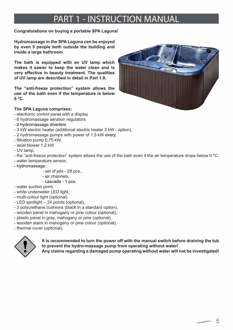
PART 1 - INSTRUCTION MANUALCongratulations on buying a portable SPA Laguna!
Hydromassage in the SPA Laguna can be enjoyed by even 5 people both outside the building and inside a large bathroom.
The bath is equipped with an UV lamp which makes it easier to keep the water clean and is very effective in beauty treatment. The qualities of UV lamp are described in detail in Part 1.8.
The “anti-freeze protection” system allows the use of the bath even if the temperature is below 0 °C.
The SPA Laguna comprises:- electronic control panel with a display- 6 hydromassage aeration regulators- 2 hydromassage diverters- 3 kW electric heater (additional electric heater 3 kW - option),- 2 hydromassage pumps with power of 1,5 kW every,- filtration pump 0,75 kW,- axial blower 1,2 kW - UV lamp,- the “anti-freeze protection” system allows the use of the bath even if the air temperature drops below 0 °C.- water temperature sensor,- hydromassage: - set of jets - 28 pcs., - air channels, - cascade - 1 pcs.- water suction point,- white underwater LED light,- multi-colour light (optional)- LED spotlight – 24 points (optional),- 3 polyurethane cushions (black in a standard option),- wooden panel in mahogany or pine colour (optional),- plastic panel in gray, mahogany or pine (optional),- wooden stairs in mahogany or pine colour (optional),- thermal cover (optional),
It is recommended to turn the power off with the manual switch before draining the tub to prevent the hydro-massage pump from operating without water!Any claims regarding a damaged pump operating without water will not be investigated!
6
1.1. TECHNICAL SPECIFICATION 2130
2130
300
250
505
600
320
80
420
520
820
940
+2
00
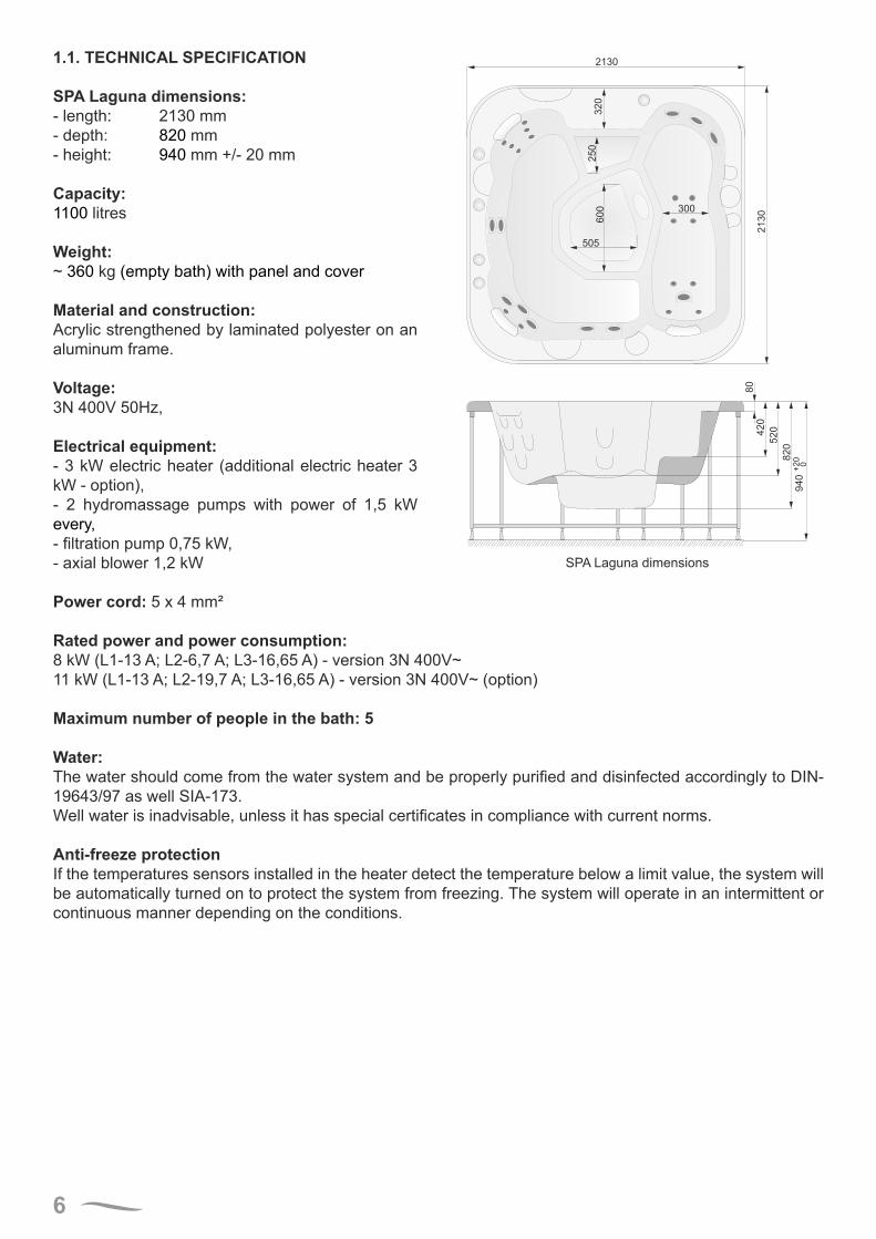
SPA Laguna dimensions:- length: 2130 mm- depth: 820 mm - height: 940 mm +/- 20 mm
Capacity:1100 litres
Weight:~ 360 kg (empty bath) with panel and cover
Material and construction:Acrylic strengthened by laminated polyester on an aluminum frame.
Voltage:3N 400V 50Hz,
SPA Laguna dimensions
Electrical equipment:- 3 kW electric heater (additional electric heater 3 kW - option),- 2 hydromassage pumps with power of 1,5 kW every,- filtration pump 0,75 kW,- axial blower 1,2 kW
Power cord: 5 x 4 mm²
Rated power and power consumption:8 kW (L1-13 A; L2-6,7 A; L3-16,65 A) - version 3N 400V~11 kW (L1-13 A; L2-19,7 A; L3-16,65 A) - version 3N 400V~ (option)
Maximum number of people in the bath: 5
Water:The water should come from the water system and be properly purified and disinfected accordingly to DIN-19643/97 as well SIA-173.Well water is inadvisable, unless it has special certificates in compliance with current norms.
Anti-freeze protectionIf the temperatures sensors installed in the heater detect the temperature below a limit value, the system will be automatically turned on to protect the system from freezing. The system will operate in an intermittent or continuous manner depending on the conditions.
7
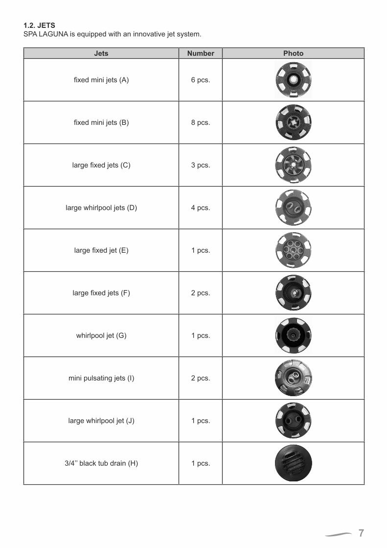
1.2. JETSSPA LAGUNA is equipped with an innovative jet system.
Jets Number Photo
fixed mini jets (A) 6 pcs.
fixed mini jets (B) 8 pcs.
large fixed jets (C) 3 pcs.
large whirlpool jets (D) 4 pcs.
large fixed jet (E) 1 pcs.
large fixed jets (F) 2 pcs.
whirlpool jet (G) 1 pcs.
mini pulsating jets (I) 2 pcs.
large whirlpool jet (J) 1 pcs.
3/4’’ black tub drain (H) 1 pcs.
8
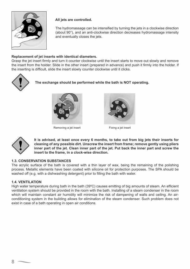
All jets are controlled.
The hydromassage can be intensified by turning the jets in a clockwise direction (about 90°), and an anti-clockwise direction decreases hydromassage intensity and eventually closes the jets.
Replacement of jet inserts with identical diameters.Grasp the jet insert firmly and turn it counter clockwise until the insert starts to move out slowly and remove the insert from the holder. Slide in the other insert (prepared in advance) and push it firmly into the holder. If the inserting is difficult, slide the insert slowly counter clockwise until it clicks.
The exchange should be performed while the bath is NOT operating.
It is advised, at least once every 6 months, to take out from big jets their inserts for cleaning of any possible dirt. Unscrew the insert from frame; remove gently using pliers inner part of the jet. Clean inner part of the jet. Put back the inner part and screw the insert to the frame, in a clock-wise direction.
1.3. CONSERVATION SUBSTANCESThe acrylic surface of the bath is covered with a thin layer of wax, being the remaining of the polishing process. Metallic elements have been coated with silicone oil for protection purposes. The SPA should be washed off (e.g. with a dishwashing detergent) prior to filling the bath with water.
1.4. VENTILATIONHigh water temperature during bath in the bath (390C) causes emitting of big amounts of steam. An efficient ventilation system should be provided in the room with the bath. Installing of a steam condenser in the room which will maintain constant air humidity will minimize the risk of dampening of walls and ceiling. An air-conditioning system in the building allows for elimination of the steam condenser. Such problem does not exist in case of a bath operating in open air conditions.
Removing a jet insert Fixing a jet insert

9
1.5. USER INTERFACE AND PROGRAMMING REFERENCE.
Laguna SPA control panel
1.5.1. THE MAIN SCREENSpa StatusThe main screen shows the most important information on the operation of the SPA bath. The screen allows the user to access the main features such as temperature adjustment. The current water temperature is displayed in the screen in large characters with the “Set temperature” being indicated below. The temperature range (High range or Low range) is indicated in the upper right hand corner. The jet icon located in the middle of the screen is displayed after the pump is started and it will change the colour once the heater is on.
A Lock icon is visible if the panel or settings are locked.
The Menu choices on the right can be selected and the screen will change to show more detailed controls or programming functions.
Set: 104°F
8:32 PM
Ozone
Filter 1
Spa
Shortcuts
Settings
High Range102°F
Ready in Rest Mode
Heating
Water Temperature
Messages
Desired Temperature
Temperature Range
Pump and Heat
Menus
Lock Indicator
Status
NavigationNavigating the entire menu structure is done with the 5 buttons on the control panel.When a text item changes to white during navigation, that indicates the item is selected for action.Operating or changing a selected item is generally done with the center button.
The only item that can be changed on the left side of the Main Screen is the Set Temperature. Press the Left Arrow button to change the Set Temperature number to white. The Set Temperature can then be adjusted with the up and down buttons. Pressing the Select button or the Right Arrow button will save the new set temperature.
10
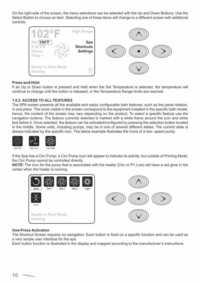
On the right side of the screen, the menu selections can be selected with the Up and Down Buttons. Use the Select Button to choose an item. Selecting one of these items will change to a different screen with additional controls.
Set: 104°F
8:32 PM
Ozone
Filter 1
Spa
Shortcuts
Settings
High Range102°F
Ready in Rest Mode
Heating
Press-and-HoldIf an Up or Down button is pressed and held when the Set Temperature is selected, the temperature will continue to change until the button is released, or the Temperature Range limits are reached.
1.5.2. ACCESS TO ALL FEATURESThe SPA screen presents all the available and easily configurable bath features, such as the panel rotation, in one place. The icons visible in the screen correspond to the equipment installed in the specific bath model, hence, the content of the screen may vary depending on the product. To select a specific feature use the navigation buttons. The feature currently selected is marked with a white frame around the icon and white text below it. Once selected, the feature can be activated/configured by pressing the selection button located in the middle. Some units, including pumps, may be in one of several different states. The current state is always indicated by the specific icon. The below example illustrates the icons of a two- speed pump.
Jets HighJets LowJets Off
If the Spa has a Circ Pump, a Circ Pump Icon will appear to indicate its activity, but outside of Priming Mode, the Circ Pump cannot be controlled directly.NOTE: The icon for the pump that is associated with the heater (Circ or P1 Low) will have a red glow in the center when the heater is running.
Ready in Rest Mode
Heating
Back Jets 1
Invert
Jets 2 Jets 3 Light
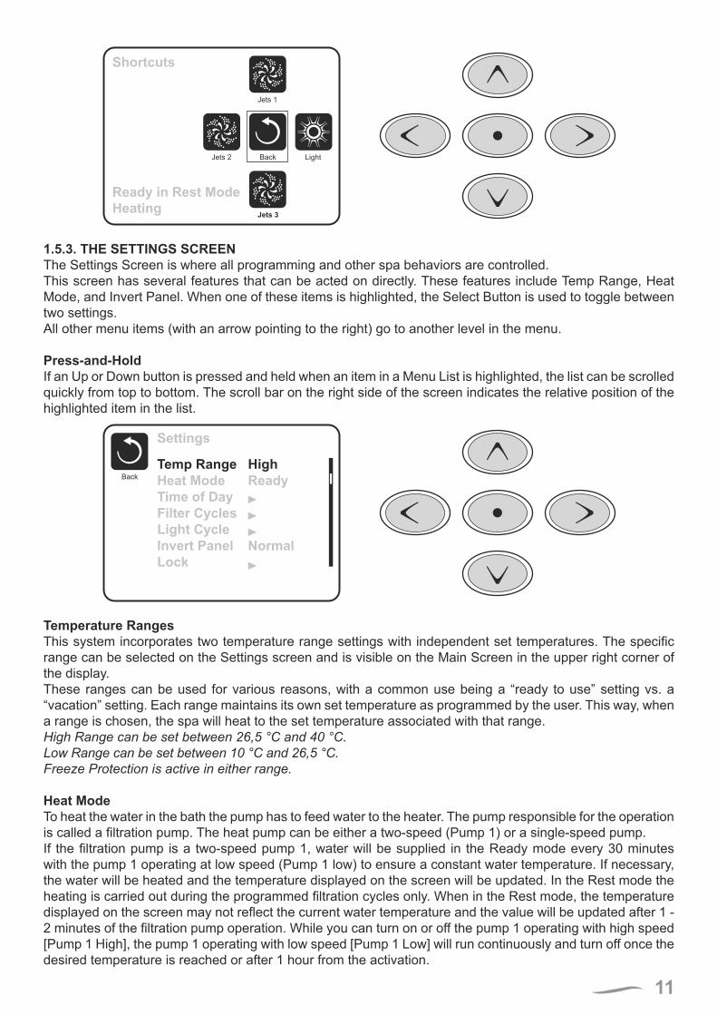
One-Press ActivationThe Shortcut Screen requires no navigation. Each button is fixed on a specific function and can be used as a very simple user interface for the spa.Each button function is illustrated in the display and mapped according to the manufacturer’s instructions.
11
Ready in Rest Mode
Heating
Shortcuts
Jets 3
Jets 2
Jets 1
LightBack
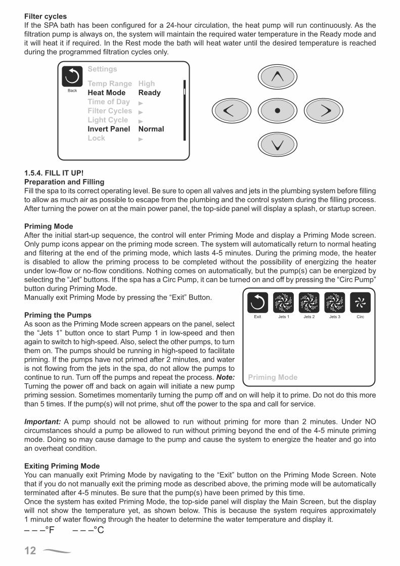
1.5.3. THE SETTINGS SCREENThe Settings Screen is where all programming and other spa behaviors are controlled.This screen has several features that can be acted on directly. These features include Temp Range, Heat Mode, and Invert Panel. When one of these items is highlighted, the Select Button is used to toggle between two settings.All other menu items (with an arrow pointing to the right) go to another level in the menu.
Press-and-HoldIf an Up or Down button is pressed and held when an item in a Menu List is highlighted, the list can be scrolled quickly from top to bottom. The scroll bar on the right side of the screen indicates the relative position of the highlighted item in the list.
Settings
Back
Temp Range
Heat Mode
Time of Day
Filter Cycles
Light Cycle
Invert Panel
Lock
High
Ready
Normal
Temperature RangesThis system incorporates two temperature range settings with independent set temperatures. The specific range can be selected on the Settings screen and is visible on the Main Screen in the upper right corner of the display.These ranges can be used for various reasons, with a common use being a “ready to use” setting vs. a “vacation” setting. Each range maintains its own set temperature as programmed by the user. This way, when a range is chosen, the spa will heat to the set temperature associated with that range.High Range can be set between 26,5 °C and 40 °C.Low Range can be set between 10 °C and 26,5 °C.Freeze Protection is active in either range.
Heat ModeTo heat the water in the bath the pump has to feed water to the heater. The pump responsible for the operation is called a filtration pump. The heat pump can be either a two-speed (Pump 1) or a single-speed pump.If the filtration pump is a two-speed pump 1, water will be supplied in the Ready mode every 30 minutes with the pump 1 operating at low speed (Pump 1 low) to ensure a constant water temperature. If necessary, the water will be heated and the temperature displayed on the screen will be updated. In the Rest mode the heating is carried out during the programmed filtration cycles only. When in the Rest mode, the temperature displayed on the screen may not reflect the current water temperature and the value will be updated after 1 - 2 minutes of the filtration pump operation. While you can turn on or off the pump 1 operating with high speed [Pump 1 High], the pump 1 operating with low speed [Pump 1 Low] will run continuously and turn off once the desired temperature is reached or after 1 hour from the activation.
12
Filter cyclesIf the SPA bath has been configured for a 24-hour circulation, the heat pump will run continuously. As the filtration pump is always on, the system will maintain the required water temperature in the Ready mode and it will heat it if required. In the Rest mode the bath will heat water until the desired temperature is reached during the programmed filtration cycles only.
Settings
Back
Temp Range
Heat Mode
Time of Day
Filter Cycles
Light Cycle
Invert Panel
Lock
High
Ready
Normal
1.5.4. FILL IT UP!Preparation and FillingFill the spa to its correct operating level. Be sure to open all valves and jets in the plumbing system before filling to allow as much air as possible to escape from the plumbing and the control system during the filling process.After turning the power on at the main power panel, the top-side panel will display a splash, or startup screen.
Priming ModeAfter the initial start-up sequence, the control will enter Priming Mode and display a Priming Mode screen. Only pump icons appear on the priming mode screen. The system will automatically return to normal heating and filtering at the end of the priming mode, which lasts 4-5 minutes. During the priming mode, the heater is disabled to allow the priming process to be completed without the possibility of energizing the heater under low-flow or no-flow conditions. Nothing comes on automatically, but the pump(s) can be energized by selecting the “Jet” buttons. If the spa has a Circ Pump, it can be turned on and off by pressing the “Circ Pump” button during Priming Mode.
Priming Mode
Exit CircJets 3Jets 2Jets 1
Manually exit Priming Mode by pressing the “Exit” Button.
Priming the PumpsAs soon as the Priming Mode screen appears on the panel, select the “Jets 1” button once to start Pump 1 in low-speed and then again to switch to high-speed. Also, select the other pumps, to turn them on. The pumps should be running in high-speed to facilitate priming. If the pumps have not primed after 2 minutes, and water is not flowing from the jets in the spa, do not allow the pumps to continue to run. Turn off the pumps and repeat the process. Note: Turning the power off and back on again will initiate a new pump priming session. Sometimes momentarily turning the pump off and on will help it to prime. Do not do this more than 5 times. If the pump(s) will not prime, shut off the power to the spa and call for service.
Important: A pump should not be allowed to run without priming for more than 2 minutes. Under NO circumstances should a pump be allowed to run without priming beyond the end of the 4-5 minute priming mode. Doing so may cause damage to the pump and cause the system to energize the heater and go into an overheat condition.
Exiting Priming ModeYou can manually exit Priming Mode by navigating to the “Exit” button on the Priming Mode Screen. Note that if you do not manually exit the priming mode as described above, the priming mode will be automatically terminated after 4-5 minutes. Be sure that the pump(s) have been primed by this time.Once the system has exited Priming Mode, the top-side panel will display the Main Screen, but the display will not show the temperature yet, as shown below. This is because the system requires approximately 1 minute of water flowing through the heater to determine the water temperature and display it.– – –°F – – –°C
13
1.5.5. SPA BEHAVIOR!PumpsOn the Spa Screen, select a “Jets” button once to turn the pump on or off, and to shift between low- and high-speeds if equipped. If left running, the pump will turn off after a time-out period. The pump 1 low-speed will time out after 30 minutes. The high-speed will time-out after 15 minutes.On non-circ systems, the low-speed of pump 1 runs when the blower or any other pump is on. If the spa is in Ready Mode, Pump 1 low may also activate for at least 1 minute every 30 minutes to detect the spa temperature (polling) and then to heat to the set temperature if needed. When the low-speed turns on automatically, it cannot be deactivated from the panel, however the high speed may be started.
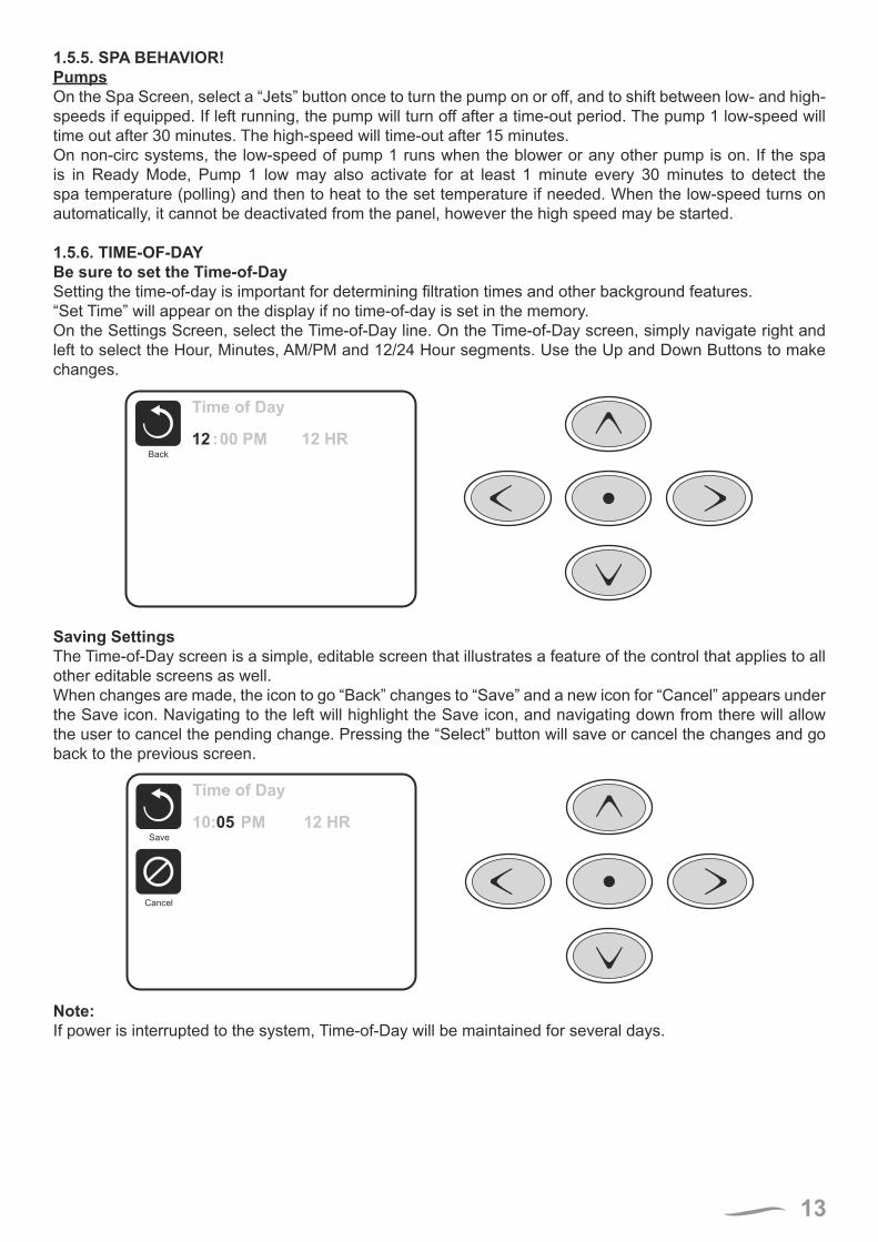
1.5.6. TIME-OF-DAYBe sure to set the Time-of-DaySetting the time-of-day is important for determining filtration times and other background features.“Set Time” will appear on the display if no time-of-day is set in the memory.On the Settings Screen, select the Time-of-Day line. On the Time-of-Day screen, simply navigate right and left to select the Hour, Minutes, AM/PM and 12/24 Hour segments. Use the Up and Down Buttons to make changes.
Time of Day
Back
12 :00 PM 12 HR
Saving SettingsThe Time-of-Day screen is a simple, editable screen that illustrates a feature of the control that applies to all other editable screens as well.When changes are made, the icon to go “Back” changes to “Save” and a new icon for “Cancel” appears under the Save icon. Navigating to the left will highlight the Save icon, and navigating down from there will allow the user to cancel the pending change. Pressing the “Select” button will save or cancel the changes and go back to the previous screen.
Time of Day
Back
12 :00 PM 12 HR
Cancel
Save
10:05 PM 12 HR
Note:If power is interrupted to the system, Time-of-Day will be maintained for several days.
14
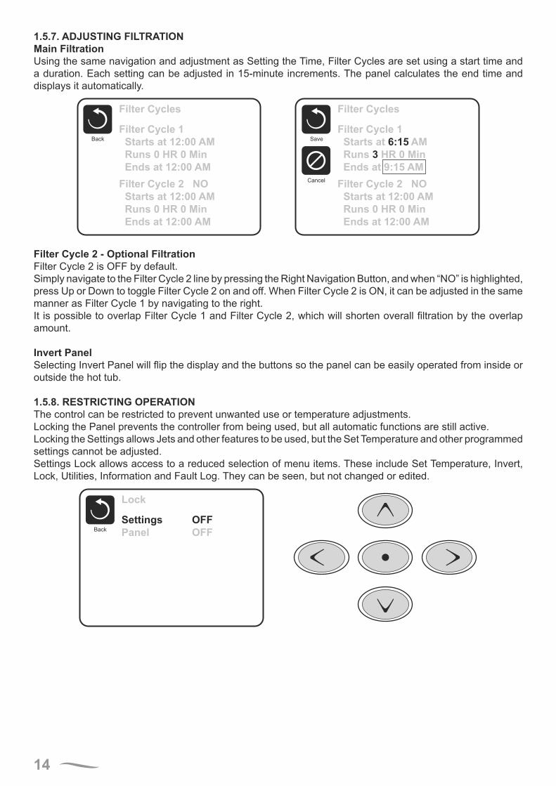
1.5.7. ADJUSTING FILTRATIONMain FiltrationUsing the same navigation and adjustment as Setting the Time, Filter Cycles are set using a start time and a duration. Each setting can be adjusted in 15-minute increments. The panel calculates the end time and displays it automatically.
Filter Cycles
Back
Filter Cycle 1
Starts at 12:00 AM
Runs 0 HR 0 Min
Ends at 12:00 AM
Filter Cycle 2 NO
Starts at 12:00 AM
Runs 0 HR 0 Min
Ends at 12:00 AM
Filter Cycles
Back
Filter Cycle 1
Starts at 6:15 AM
Runs 3 HR 0 Min
Ends at 9:15 AM
Filter Cycle 2 NO
Starts at 12:00 AM
Runs 0 HR 0 Min
Ends at 12:00 AM
Cancel
Save
Filter Cycle 2 - Optional FiltrationFilter Cycle 2 is OFF by default.Simply navigate to the Filter Cycle 2 line by pressing the Right Navigation Button, and when “NO” is highlighted, press Up or Down to toggle Filter Cycle 2 on and off. When Filter Cycle 2 is ON, it can be adjusted in the same manner as Filter Cycle 1 by navigating to the right.It is possible to overlap Filter Cycle 1 and Filter Cycle 2, which will shorten overall filtration by the overlap amount.
Invert PanelSelecting Invert Panel will flip the display and the buttons so the panel can be easily operated from inside or outside the hot tub.
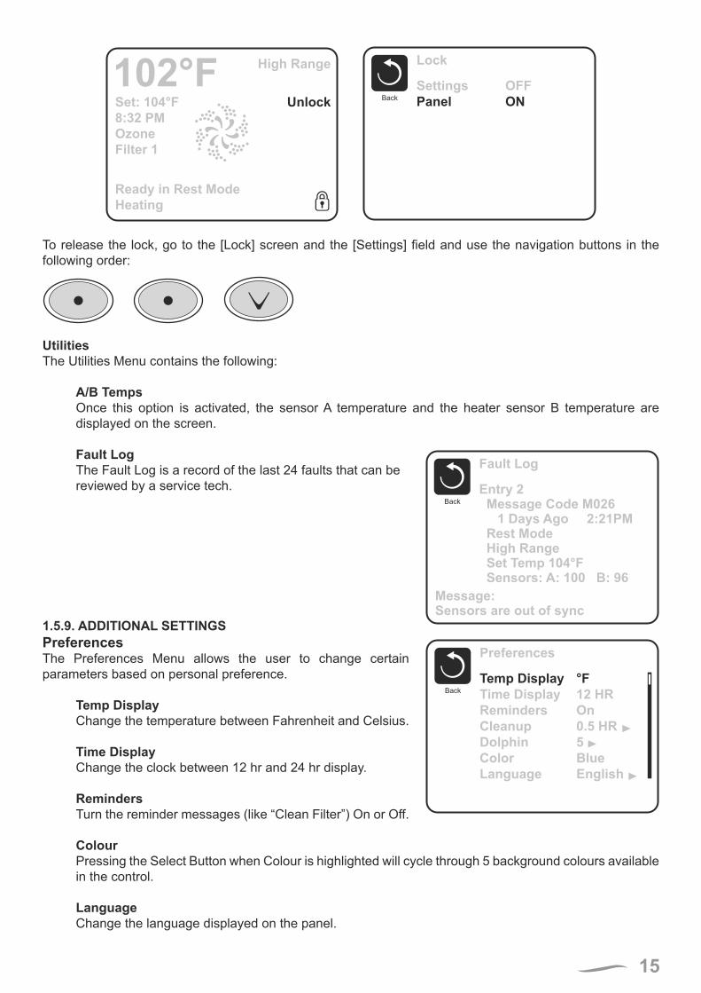
1.5.8. RESTRICTING OPERATIONThe control can be restricted to prevent unwanted use or temperature adjustments.Locking the Panel prevents the controller from being used, but all automatic functions are still active.Locking the Settings allows Jets and other features to be used, but the Set Temperature and other programmed settings cannot be adjusted.Settings Lock allows access to a reduced selection of menu items. These include Set Temperature, Invert, Lock, Utilities, Information and Fault Log. They can be seen, but not changed or edited.
Lock
Back
Settings
Panel
OFF
OFF
15
Lock
Back
Settings
Panel
OFF
ONSet: 104°F
8:32 PM
Ozone
Filter 1
Unlock
High Range102°F
Ready in Rest Mode
Heating
To release the lock, go to the [Lock] screen and the [Settings] field and use the navigation buttons in the following order:
UtilitiesThe Utilities Menu contains the following:
A/B TempsOnce this option is activated, the sensor A temperature and the heater sensor B temperature are displayed on the screen.
Fault LogFault Log
Back
Entry 2Message Code M026
1 Days Ago 2:21PMRest ModeHigh RangeSet Temp 104°FSensors: A: 100 B: 96
Message:Sensors are out of sync
The Fault Log is a record of the last 24 faults that can bereviewed by a service tech.
1.5.9. ADDITIONAL SETTINGSPreferences
Preferences
Back
Temp Display
Time Display
Reminders
Cleanup
Dolphin
Color
Language
°F
12 HR
On
0.5 HR
5
Blue
English
The Preferences Menu allows the user to change certain parameters based on personal preference.
Temp DisplayChange the temperature between Fahrenheit and Celsius.
Time DisplayChange the clock between 12 hr and 24 hr display.
RemindersTurn the reminder messages (like “Clean Filter”) On or Off.
ColourPressing the Select Button when Colour is highlighted will cycle through 5 background colours available in the control.
LanguageChange the language displayed on the panel.
16
1.5.10. INFORMATIONSystem Information System Information
Back
Software ID (SSID)
System Model
Current Setup
Configuration Signature
Heater Voltage
Heater Type
Software ID (SSID):
M100_101 V0.6
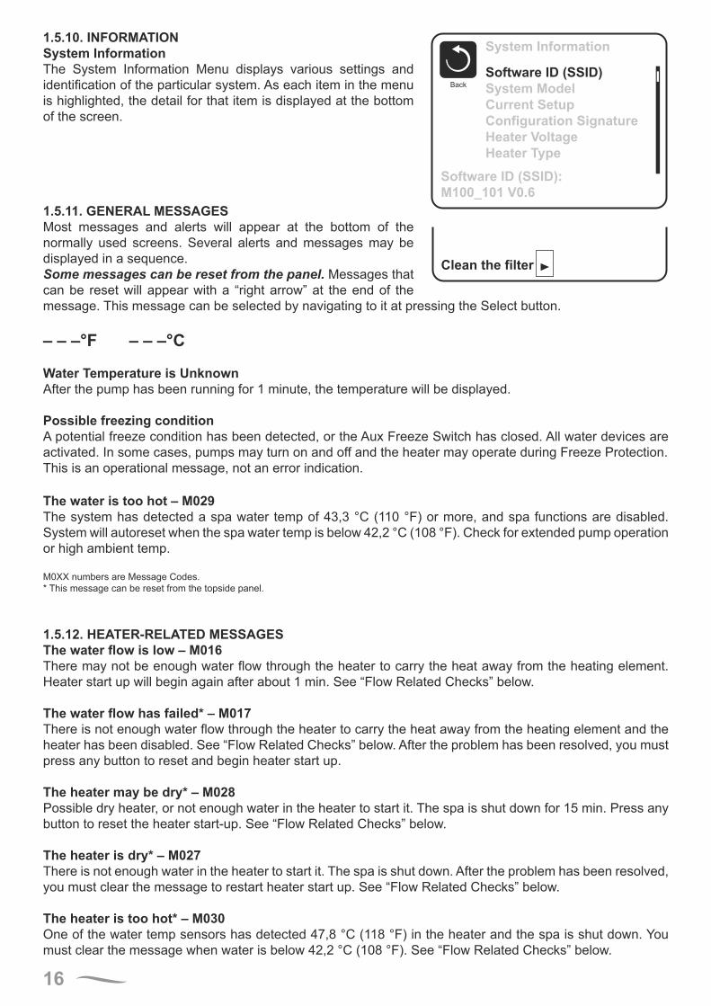
The System Information Menu displays various settings and identification of the particular system. As each item in the menu is highlighted, the detail for that item is displayed at the bottom of the screen.
1.5.11. GENERAL MESSAGES
Clean the filter
Most messages and alerts will appear at the bottom of the normally used screens. Several alerts and messages may be displayed in a sequence.Some messages can be reset from the panel. Messages that can be reset will appear with a “right arrow” at the end of the message. This message can be selected by navigating to it at pressing the Select button.
– – –°F – – –°C
Water Temperature is UnknownAfter the pump has been running for 1 minute, the temperature will be displayed.
Possible freezing conditionA potential freeze condition has been detected, or the Aux Freeze Switch has closed. All water devices are activated. In some cases, pumps may turn on and off and the heater may operate during Freeze Protection.This is an operational message, not an error indication.
The water is too hot – M029The system has detected a spa water temp of 43,3 °C (110 °F) or more, and spa functions are disabled. System will autoreset when the spa water temp is below 42,2 °C (108 °F). Check for extended pump operation or high ambient temp.
M0XX numbers are Message Codes.* This message can be reset from the topside panel.
1.5.12. HEATER-RELATED MESSAGESThe water flow is low – M016There may not be enough water flow through the heater to carry the heat away from the heating element. Heater start up will begin again after about 1 min. See “Flow Related Checks” below.
The water flow has failed* – M017There is not enough water flow through the heater to carry the heat away from the heating element and the heater has been disabled. See “Flow Related Checks” below. After the problem has been resolved, you must press any button to reset and begin heater start up.
The heater may be dry* – M028Possible dry heater, or not enough water in the heater to start it. The spa is shut down for 15 min. Press any button to reset the heater start-up. See “Flow Related Checks” below.
The heater is dry* – M027There is not enough water in the heater to start it. The spa is shut down. After the problem has been resolved, you must clear the message to restart heater start up. See “Flow Related Checks” below.
The heater is too hot* – M030One of the water temp sensors has detected 47,8 °C (118 °F) in the heater and the spa is shut down. You must clear the message when water is below 42,2 °C (108 °F). See “Flow Related Checks” below.
17
Flow-Related ChecksCheck for low water level, suction flow restrictions, closed valves, trapped air, too many closed jets and pump prime.
On some systems, even when spa is shut down by an error condition, some equipment may occasionally turn on to continue monitoring temperature or if freeze protection is needed.
M0XX numbers are Message Codes.* This message can be reset from the topside panel.
1.5.13. SENSOR-RELATED MESSAGESSensors are out of sync – M015The temperature sensors MAY be out of sync by 2° or 3°. Call for Service.
Sensors are out of sync -- Call for service* – M026The temperature sensors ARE out of sync. The fault above has been established for at least 1 hour.Call for Service.
Sensor A Fault, Sensor B Fault – Sensor A: M031, Sensor B: M032A temperature sensor or sensor circuit has failed. Call for Service.
1.5.14. MISCELLANEOUS MESSAGESCommunications errorThe control panel is not receiving communication from the System. Call for Service.
Test software installedThe Control System is operating with test software. Call for Service.
°F or °C is replaced by °TThe Control System is in Test Mode. Call for Service.
M0XX numbers are Message Codes.* This message can be reset from the topside panel.
1.5.15. SYSTEM-RELATED MESSAGESProgram memory failure* – M022At Power-Up, the system has failed the Program Checksum Test. This indicates a problem with the firmware (operation program) and requires a service call.
The settings have been reset (Persistent Memory Error)* – M021Contact your dealer or service organization if this message appears on more than one power-up.
The clock has failed* – M020Contact your dealer or service organization.
Configuration error (SPA will not Start Up)Contact your dealer or service organization.
A pump may be stuck on – M034Water may be overheated. POWER DOWN THE SPA. DO NOT ENTER THE WATER. Contact your dealer or service organization.
Hot fault – M035A Pump Appears to have been Stuck ON when spa was last poweredPOWER DOWN THE SPA. DO NOT ENTER THE WATER. Contact your dealer or service organization.
M0XX numbers are Message Codes.* This message can be reset from the topside panel.

18
1.5.16. REMINDER MESSAGESGeneral maintenance helps.Reminder Messages can be suppressed by using the Preferences Menu.Reminder Messages can be chosen individually by the Manufacturer. They may be disabled entirely, or there may be a limited number of reminders on a specific model. The frequency of each reminder (i.e. 7 days) can be specified by the Manufacturer.
Check the pHMay appear on a regular schedule, i.e. every 7 days.Check pH with a test kit and adjust pH with the appropriate chemicals.
Check the sanitizerMay appear on a regular schedule, i.e. every 7 days.Check sanitizer level and other water chemistry with a test kit and adjust with the appropriate chemicals.
Clean the filterMay appear on a regular schedule, i.e. every 30 days.Clean the filter media as instructed by the manufacturer.
Change the waterMay appear on a regular schedule, i.e. every 90 days.Change the water in the spa on regular basis to maintain proper chemical balance and sanitary conditions.
Clean the coverMay appear on a regular schedule, i.e. every 180 days.Vinyl covers should be cleaned and conditioned for maximum life.
Treat the woodMay appear on a regular schedule, i.e. every 180 days.Wood skirting and furniture should be cleaned and conditioned per the manufacturers instructions for maximum life.
Change the filterMay appear on a regular schedule, i.e. every 365 days.Filters should be replaced occasionally to maintain proper spa function and sanitary conditions.
Reminder messages can be reset from the topside panel.Additional messages may appear on specific systems.
1.5.17. WARNING! QUALIFIED TECHNICIAN REQUIRED FOR SERVICE AND INSTALLATIONWarning: People with infectious diseases should not use a spa or hot tub.Warning: To avoid injury, exercise care when entering or exiting the spa or hot tub.Warning: Do not use a spa or hot tub immediately following strenuous exercise.Warning: Prolonged immersion in a spa or hot tub may be injurious to your health.Warning: Maintain water chemistry in accordance with the Manufacturers instructions.
Warning! GFCI or RCD ProtectionThe Owner should test and reset the GFCI or RCD on a regular basis to verify its function.
Warning! Shock Hazard!
Do not attempt service of this control system. Contact your dealer or service organization for assistance. Follow all owner’s manual power connection instructions. Installation must be performed by a licensed electrician and all grounding connections must be properly installed.
19
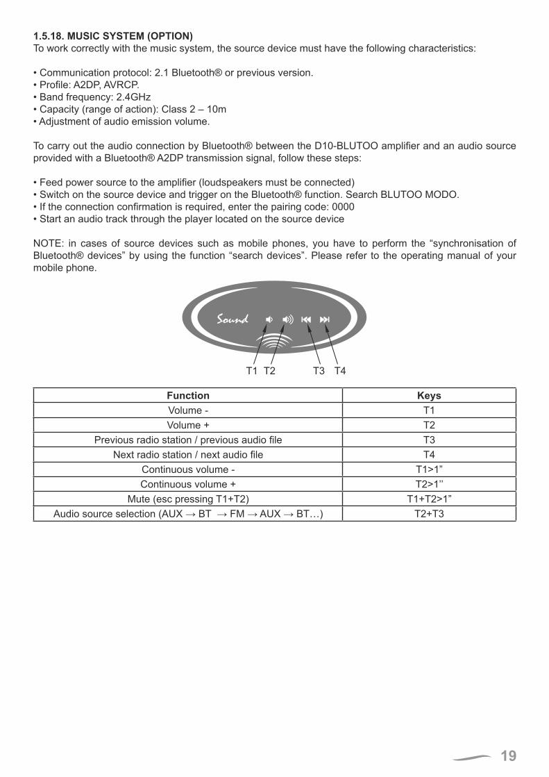
1.5.18. MUSIC SYSTEM (OPTION)To work correctly with the music system, the source device must have the following characteristics:
• Communication protocol: 2.1 Bluetooth® or previous version.• Profile: A2DP, AVRCP.• Band frequency: 2.4GHz• Capacity (range of action): Class 2 – 10m• Adjustment of audio emission volume.
To carry out the audio connection by Bluetooth® between the D10-BLUTOO amplifier and an audio source provided with a Bluetooth® A2DP transmission signal, follow these steps:
• Feed power source to the amplifier (loudspeakers must be connected)• Switch on the source device and trigger on the Bluetooth® function. Search BLUTOO MODO.• If the connection confirmation is required, enter the pairing code: 0000• Start an audio track through the player located on the source device
NOTE: in cases of source devices such as mobile phones, you have to perform the “synchronisation of Bluetooth® devices” by using the function “search devices”. Please refer to the operating manual of your mobile phone.
Sound
T1 T2 T3 T4
Function KeysVolume - T1Volume + T2
Previous radio station / previous audio file T3Next radio station / next audio file T4
Continuous volume - T1>1”Continuous volume + T2>1’’
Mute (esc pressing T1+T2) T1+T2>1”Audio source selection (AUX → BT → FM → AUX → BT…) T2+T3
20
1.5.19. CONTROL YOUR HOT TUB FROM YOUR SMARTPHONE (OPTION)The Balboa Worldwide App (bwa™), is an app for your smart device (Android™ or iPhone®) that allows you to access your hot tub via a direct connection anywhere in the local proximity of your tub, anywhere in your house that you can connect to your local Wi-Fi network, or anywhere in the World you have an Internet connection to your smart device via 3G, 4G, or Wi-Fi hot spots.
With the bwa app, you can ensure that your hot tub will be ready whenever you want to take a dip. Instead of going outside and pressing buttons on the topside panel, the app lets you start the tub and change settings from your smartphone or tablet.
The app provides full interface control so you can set the temperature, turn pumps on and off and even set filtration cycles.
GETTING READY
You’re just several easy steps away from connecting your tub to your home network and the Internet. Before you begin, you might want to record some information for your records and to help troubleshoot your setup if needed.
Before the next step, write down the name of your wireless network, password and the encryption type. If you do not know the above data, contact your network administrator, the person who helped you to configure the wireless router or refer to the relevant manuals. You will also need to check if the wireless connection is available at the place where the tub is located.
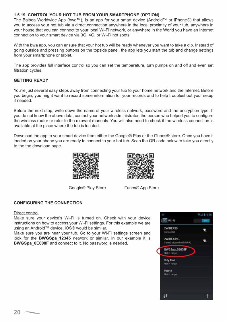
Download the app to your smart device from either the Google® Play or the iTunes® store. Once you have it loaded on your phone you are ready to connect to your hot tub. Scan the QR code below to take you directly to the the download page.
Google® Play Store iTunes® App Store
CONFIGURING THE CONNECTION
Direct controlMake sure your device’s Wi-Fi is turned on. Check with your device instructions on how to access your Wi-Fi settings. For this example we are using an Android™ device, iOS® would be similar.Make sure you are near your tub. Go to your Wi-Fi settings screen and look for the BWGSpa_12345 network or similar. In our example it is BWGSpa_0E608F and connect to it. No password is needed.
21
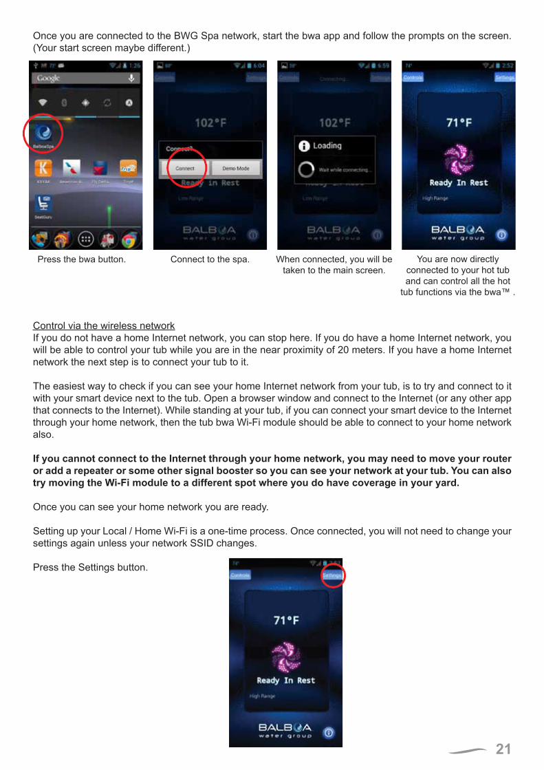
Once you are connected to the BWG Spa network, start the bwa app and follow the prompts on the screen. (Your start screen maybe different.)
Control via the wireless networkIf you do not have a home Internet network, you can stop here. If you do have a home Internet network, you will be able to control your tub while you are in the near proximity of 20 meters. If you have a home Internet network the next step is to connect your tub to it.
The easiest way to check if you can see your home Internet network from your tub, is to try and connect to it with your smart device next to the tub. Open a browser window and connect to the Internet (or any other app that connects to the Internet). While standing at your tub, if you can connect your smart device to the Internet through your home network, then the tub bwa Wi-Fi module should be able to connect to your home network also.
If you cannot connect to the Internet through your home network, you may need to move your router or add a repeater or some other signal booster so you can see your network at your tub. You can also try moving the Wi-Fi module to a different spot where you do have coverage in your yard.
Once you can see your home network you are ready.
Setting up your Local / Home Wi-Fi is a one-time process. Once connected, you will not need to change your settings again unless your network SSID changes.
Press the Settings button.
Connect to the spa. You are now directly connected to your hot tub and can control all the hot
tub functions via the bwa™ .
Press the bwa button. When connected, you will be taken to the main screen.

22
On the next screen, you will select the Advanced button to set up your Wi-Fi network settings
CONFIGURATION IN ANDROID SYSTEM
THE WI-FI SCREENADVANCED SETTINGSSETTINGS SCREEN
The Settings screen allows you to select the temperature of the spa, change the temperature between Fº and Cº, set
time of day, filter cycles and more. Press the Advanced button to setup your Wi-Fi.
If you have a router that supports WPS provisioning,
select that box and press the WPS button on your
home router. Not all routers support the WPS function.
Check your router’s instructions for more details.
On the Wi-Fi screen you can use the drop down menu to select your network SSID or you can enter it in the SSID
box. You will also need to choose
the type of password encryption you are using:
Open, WEP, or WPA.
Now select the Wi-Fi Settings button, to select your home network and enter your password.
Configuration in Android™ and iOS® systems is
described in the following pages.
ENTER PASSWORD SCREEN CONFIRM SCREEN Wi-Fi LINK SCREEN
Select the Key text box to enter your password if you have one. Type it in using
the keyboard.
You may need to connect to your home network after you
save the password.Exit the app and make sure you are connected to your
home network.
You will be asked to confirm that you want to update your
password to the spa. The BWG Spa network will now disconnect and you will be controlling your tub via your
home network.
Now you will save the password to the hot tub
and the tub will be ready to connect to your network. Press the Save Button.
23
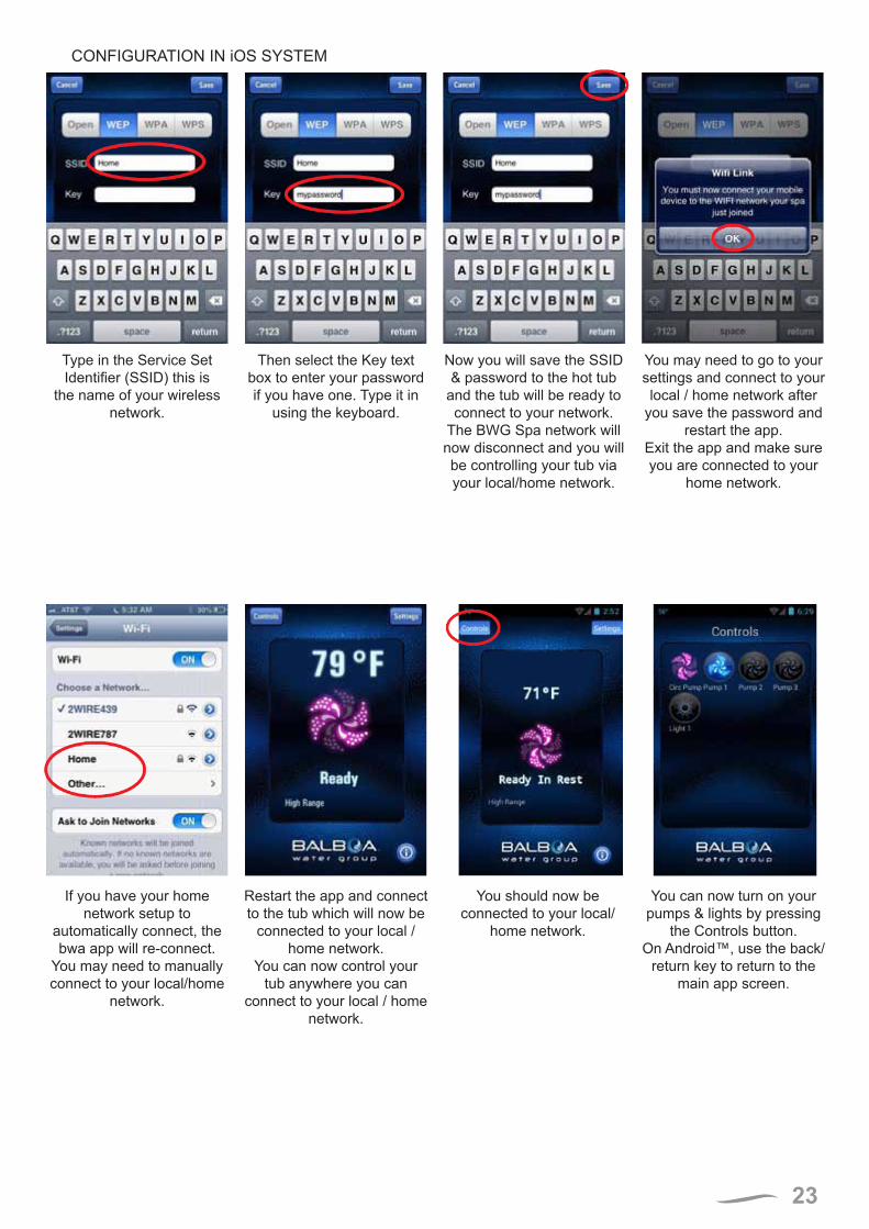
CONFIGURATION IN iOS SYSTEM
Type in the Service Set Identifier (SSID) this is
the name of your wireless network.
You may need to go to your settings and connect to your local / home network after
you save the password and restart the app.
Exit the app and make sure you are connected to your
home network.
Now you will save the SSID & password to the hot tub
and the tub will be ready to connect to your network.
The BWG Spa network will now disconnect and you will be controlling your tub via your local/home network.
Then select the Key text box to enter your password if you have one. Type it in
using the keyboard.
If you have your home network setup to
automatically connect, the bwa app will re-connect.
You may need to manually connect to your local/home
network.
You can now turn on your pumps & lights by pressing
the Controls button.On Android™, use the back/
return key to return to the main app screen.
You should now be connected to your local/
home network.
Restart the app and connect to the tub which will now be
connected to your local / home network.
You can now control your tub anywhere you can
connect to your local / home network.
24
RESETTING THE WI-FI RECEIVER
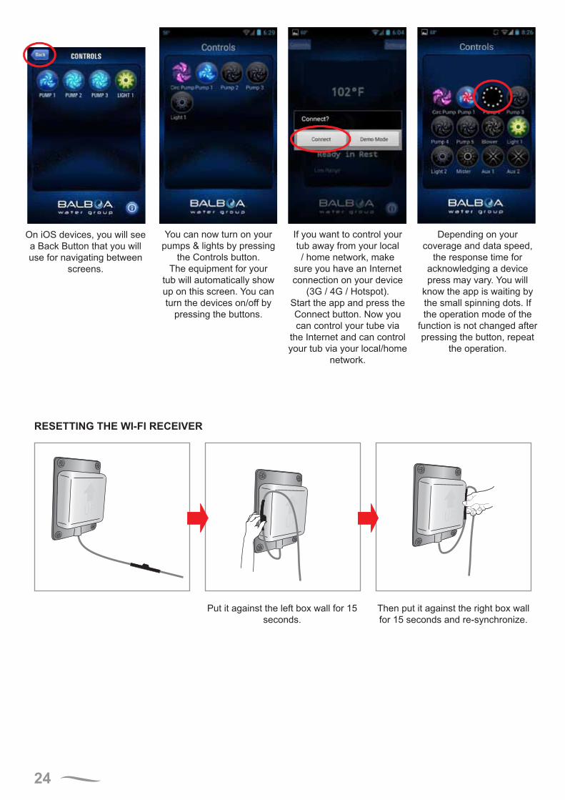
Depending on your coverage and data speed,
the response time for acknowledging a device press may vary. You will
know the app is waiting by the small spinning dots. If the operation mode of the
function is not changed after pressing the button, repeat
the operation.
On iOS devices, you will see a Back Button that you will use for navigating between
screens.
If you want to control your tub away from your local / home network, make
sure you have an Internet connection on your device
(3G / 4G / Hotspot).Start the app and press the Connect button. Now you can control your tube via
the Internet and can control your tub via your local/home
network.
You can now turn on your pumps & lights by pressing
the Controls button. The equipment for your
tub will automatically show up on this screen. You can turn the devices on/off by
pressing the buttons.
Put it against the left box wall for 15 seconds.
Then put it against the right box wall for 15 seconds and re-synchronize.
25
BASIC OPERATION
INFORMATION MESSAGES
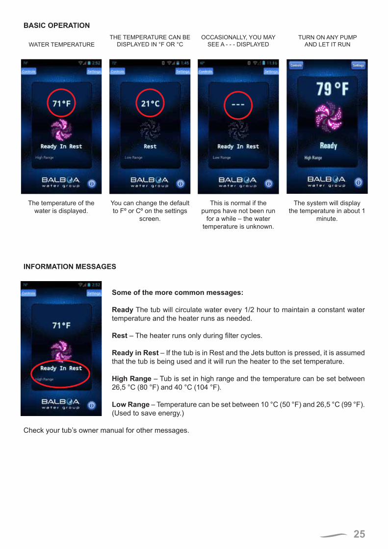
Some of the more common messages:
Ready The tub will circulate water every 1/2 hour to maintain a constant water temperature and the heater runs as needed.
Rest – The heater runs only during filter cycles.
Ready in Rest – If the tub is in Rest and the Jets button is pressed, it is assumed that the tub is being used and it will run the heater to the set temperature.
High Range – Tub is set in high range and the temperature can be set between 26,5 °C (80 °F) and 40 °C (104 °F).
Low Range – Temperature can be set between 10 °C (50 °F) and 26,5 °C (99 °F). (Used to save energy.)
Check your tub’s owner manual for other messages.
WATER TEMPERATURETURN ON ANY PUMP
AND LET IT RUNOCCASIONALLY, YOU MAY
SEE A - - - DISPLAYEDTHE TEMPERATURE CAN BE
DISPLAYED IN °F OR °C
The temperature of the water is displayed.
The system will display the temperature in about 1
minute.
This is normal if the pumps have not been run
for a while – the water temperature is unknown.
You can change the default to Fº or Cº on the settings
screen.
26
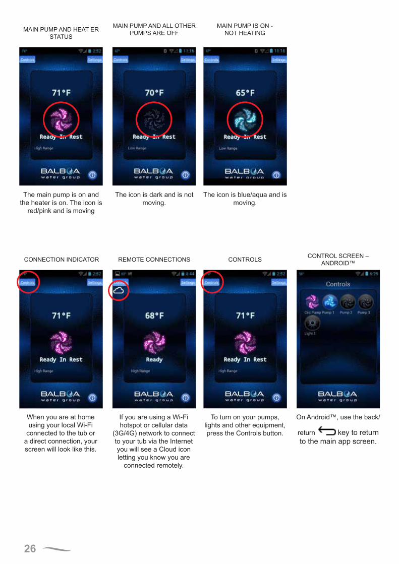
MAIN PUMP AND HEAT ER STATUS
MAIN PUMP AND ALL OTHER PUMPS ARE OFF
MAIN PUMP IS ON - NOT HEATING
The main pump is on and the heater is on. The icon is
red/pink and is moving
The icon is dark and is not moving.
The icon is blue/aqua and is moving.
CONNECTION INDICATOR REMOTE CONNECTIONS CONTROLS CONTROL SCREEN – ANDROID™
When you are at home using your local Wi-Fi
connected to the tub or a direct connection, your screen will look like this.
On Android™, use the back/
return key to return to the main app screen.
To turn on your pumps, lights and other equipment, press the Controls button.
If you are using a Wi-Fi hotspot or cellular data
(3G/4G) network to connect to your tub via the Internet you will see a Cloud icon letting you know you are
connected remotely.
27
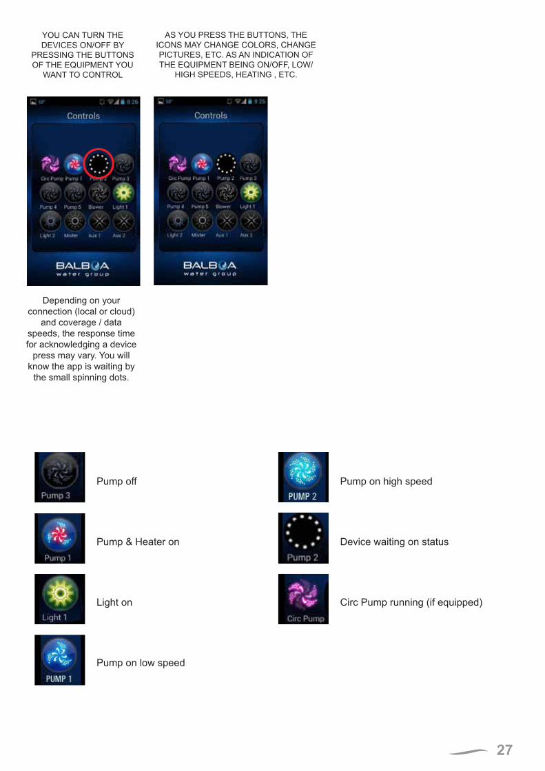
Pump off Pump on high speed
Pump & Heater on Device waiting on status
Light on Circ Pump running (if equipped)
Pump on low speed
AS YOU PRESS THE BUTTONS, THE ICONS MAY CHANGE COLORS, CHANGE PICTURES, ETC. AS AN INDICATION OF THE EQUIPMENT BEING ON/OFF, LOW/
HIGH SPEEDS, HEATING , ETC.
YOU CAN TURN THE DEVICES ON/OFF BY
PRESSING THE BUTTONS OF THE EQUIPMENT YOU
WANT TO CONTROL
Depending on your connection (local or cloud)
and coverage / data speeds, the response time for acknowledging a device
press may vary. You will know the app is waiting by
the small spinning dots.
28
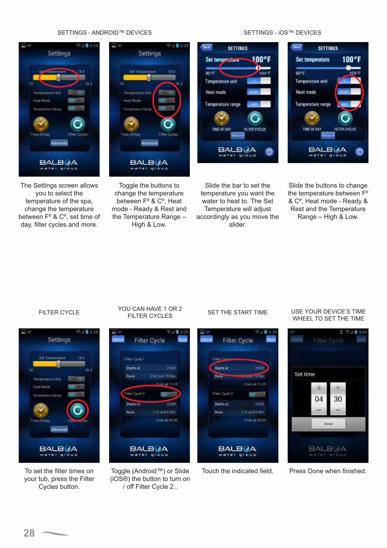
SETTINGS - ANDROID™ DEVICES SETTINGS - iOS™ DEVICES
The Settings screen allowsyou to select the
temperature of the spa, change the temperature
between Fº & Cº, set time of day, filter cycles and more.
Slide the buttons to change the temperature between Fº & Cº, Heat mode - Ready & Rest and the Temperature
Range – High & Low.
Slide the bar to set the temperature you want the water to heat to. The Set Temperature will adjust
accordingly as you move the slider.
Toggle the buttons to change the temperature between Fº & Cº, Heat
mode - Ready & Rest and the Temperature Range –
High & Low.
FILTER CYCLE YOU CAN HAVE 1 OR 2FILTER CYCLES SET THE START TIME USE YOUR DEVICE’S TIME
WHEEL TO SET THE TIME
To set the filter times on your tub, press the Filter
Cycles button.
Touch the indicated field. Press Done when finished.Toggle (Android™) or Slide (iOS®) the button to turn on
/ off Filter Cycle 2..
29
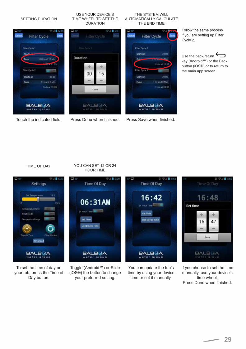
SETTING DURATIONUSE YOUR DEVICE’S
TIME WHEEL TO SET THE DURATION
THE SYSTEM WILL AUTOMATICALLY CALCULATE
THE END TIME
Follow the same process if you are setting up Filter Cycle 2.
Use the back/return key (Android™) or the Back button (iOS®) or to return to the main app screen.
Press Done when finished. Press Save when finished.Touch the indicated field.
TIME OF DAY YOU CAN SET 12 OR 24HOUR TIME
To set the time of day on your tub, press the Time of
Day button.
Toggle (Android™) or Slide (iOS®) the button to change
your preferred setting.
You can update the tub’s time by using your device
time or set it manually.
If you choose to set the time manually, use your device’s
time wheel.Press Done when finished.
30
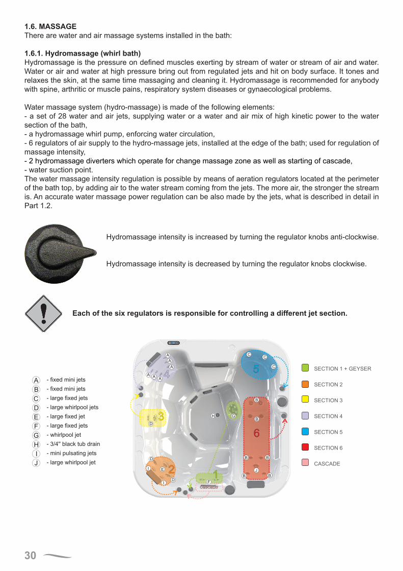
1.6. MASSAGEThere are water and air massage systems installed in the bath:
1.6.1. Hydromassage (whirl bath)Hydromassage is the pressure on defined muscles exerting by stream of water or stream of air and water. Water or air and water at high pressure bring out from regulated jets and hit on body surface. It tones and relaxes the skin, at the same time massaging and cleaning it. Hydromassage is recommended for anybody with spine, arthritic or muscle pains, respiratory system diseases or gynaecological problems.
Water massage system (hydro-massage) is made of the following elements:- a set of 28 water and air jets, supplying water or a water and air mix of high kinetic power to the water section of the bath,- a hydromassage whirl pump, enforcing water circulation,- 6 regulators of air supply to the hydro-massage jets, installed at the edge of the bath; used for regulation of massage intensity,- 2 hydromassage diverters which operate for change massage zone as well as starting of cascade,- water suction point.The water massage intensity regulation is possible by means of aeration regulators located at the perimeter of the bath top, by adding air to the water stream coming from the jets. The more air, the stronger the stream is. An accurate water massage power regulation can be also made by the jets, what is described in detail in Part 1.2.
Hydromassage intensity is increased by turning the regulator knobs anti-clockwise.
Hydromassage intensity is decreased by turning the regulator knobs clockwise.
Each of the six regulators is responsible for controlling a different jet section.
4
3
2
6
5
cascade
A
A
A
AA
A
D
D
D
EI
I F
H G
J
B
B
B
B
CC
C
1 B
B
SECTION 1 + GEYSER
SECTION 2
SECTION 3
SECTION 4
SECTION 5
SECTION 6
CASCADE
A
B
C
D
E
F
G
H
I
J
- fixed mini jets
- fixed mini jets
- large fixed jets
- large whirlpool jets
- large fixed jet
- large fixed jets
whirlpool jet
pulsating jets
large whirlpool jet
-
-
- mini
-
3/4'' black tub drain
31
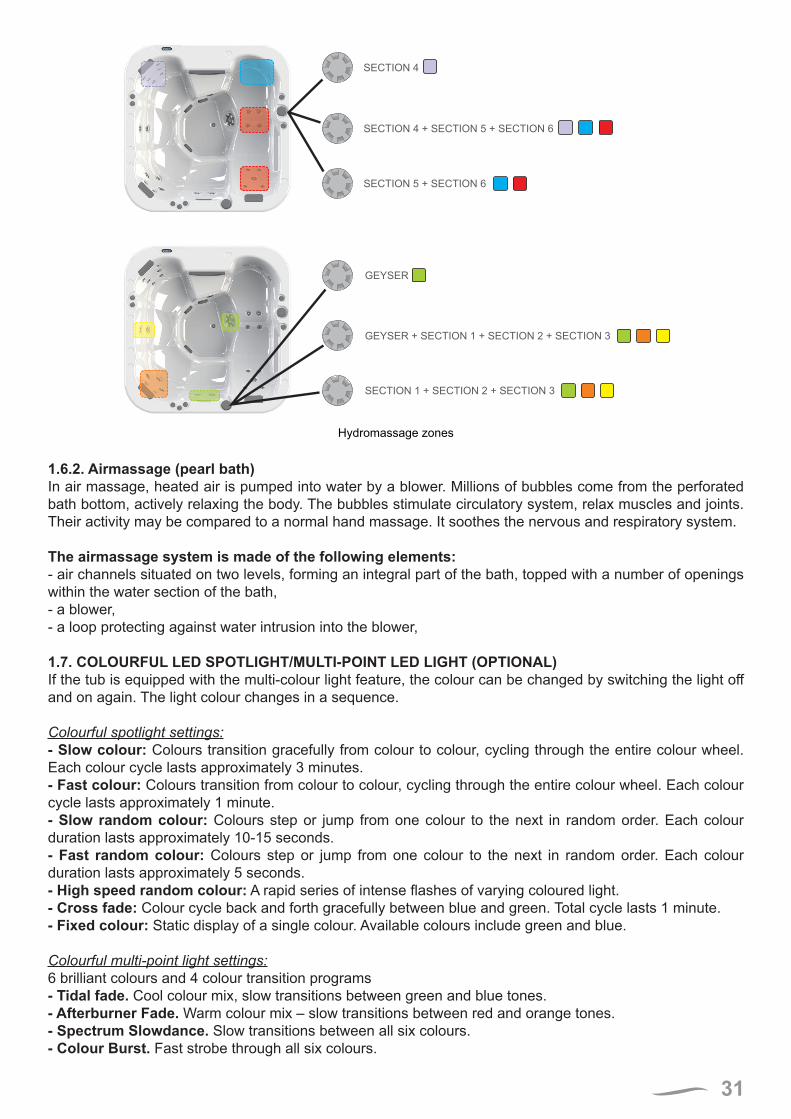
SECTION 5 + SECTION 6
SECTION 4 + SECTION 5 + SECTION 6
SECTION 4
SECTION SECTION SECTION1 + 2 + 3
GEYSER + 1 + 2 + 3SECTION SECTION SECTION
GEYSER
Hydromassage zones
1.6.2. Airmassage (pearl bath)In air massage, heated air is pumped into water by a blower. Millions of bubbles come from the perforated bath bottom, actively relaxing the body. The bubbles stimulate circulatory system, relax muscles and joints. Their activity may be compared to a normal hand massage. It soothes the nervous and respiratory system.
The airmassage system is made of the following elements:- air channels situated on two levels, forming an integral part of the bath, topped with a number of openings within the water section of the bath,- a blower,- a loop protecting against water intrusion into the blower,
1.7. COLOURFUL LED SPOTLIGHT/MULTI-POINT LED LIGHT (OPTIONAL)If the tub is equipped with the multi-colour light feature, the colour can be changed by switching the light off and on again. The light colour changes in a sequence.
Colourful spotlight settings:- Slow colour: Colours transition gracefully from colour to colour, cycling through the entire colour wheel. Each colour cycle lasts approximately 3 minutes.- Fast colour: Colours transition from colour to colour, cycling through the entire colour wheel. Each colour cycle lasts approximately 1 minute.- Slow random colour: Colours step or jump from one colour to the next in random order. Each colour duration lasts approximately 10-15 seconds.- Fast random colour: Colours step or jump from one colour to the next in random order. Each colour duration lasts approximately 5 seconds.- High speed random colour: A rapid series of intense flashes of varying coloured light.- Cross fade: Colour cycle back and forth gracefully between blue and green. Total cycle lasts 1 minute.- Fixed colour: Static display of a single colour. Available colours include green and blue.
Colourful multi-point light settings:6 brilliant colours and 4 colour transition programs- Tidal fade. Cool colour mix, slow transitions between green and blue tones.- Afterburner Fade. Warm colour mix – slow transitions between red and orange tones.- Spectrum Slowdance. Slow transitions between all six colours.- Colour Burst. Fast strobe through all six colours.
32
1.8. UV LAMPA special UV lamp generates UV-C radiation with a wavelength of 253,7 nm, which neutralizes bacteria, viruses and other primitive organisms, preventing their reproduction at the same time.
The benefits of UV-C radiation:- ensures fresh, clean and clear water- disinfects water safely and efficiently- keeps the formation of mold, bacteria and algae under control- reduces the use of chorine and other chemicals by up to 80%- prevents the smell of chlorine as well as skin and eye irritation (including eye redness)- is more environmentally-friendly than traditional methods.
UV lamp work only during filtration.
1.9. LAGUNA SPA FILTRATION SYSTEMSPA LAGUNA filtration system comprises:- F500 sand filter (sand filter used in Laguna bath has a filter area of 0.20 m2)- skimmer filter - filtration and massage pump- water filter (with a renewable cartridge for multiple use),- water suction point,- PVC fittings and pipes (PVC parts to connect the bath to the machine room are not included as the standard equipment)
The bath is equipped with two types of filters: sand and cartridge filters. The user may select the filtration type to be used.
It is prohibited to use both filtration types at the same time as it may damage the circulation pump and render the manufacturer’s warranty for the filtration circulation pump null and void.
If the filtration with a sand filter has been selected, remove the cartridge filters from the skimmer. If the cartridge filters have been selected, set the sand filter valve lever at CIRCULATION position.
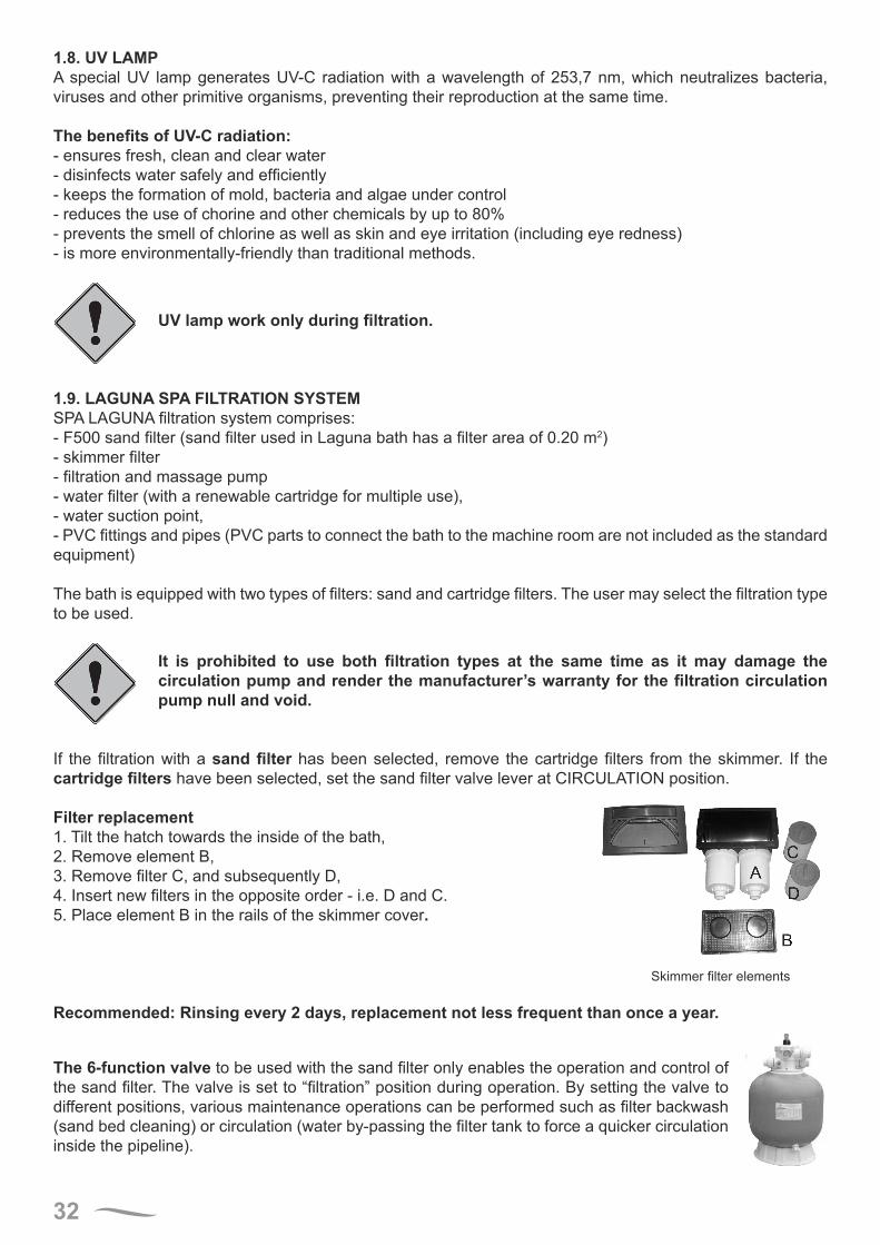
Filter replacement1. Tilt the hatch towards the inside of the bath,2. Remove element B,3. Remove filter C, and subsequently D,4. Insert new filters in the opposite order - i.e. D and C.5. Place element B in the rails of the skimmer cover.
Skimmer filter elements
Recommended: Rinsing every 2 days, replacement not less frequent than once a year.
The 6-function valve to be used with the sand filter only enables the operation and control of the sand filter. The valve is set to “filtration” position during operation. By setting the valve to different positions, various maintenance operations can be performed such as filter backwash (sand bed cleaning) or circulation (water by-passing the filter tank to force a quicker circulation inside the pipeline).
33
To change the sand valve lever position, uninstall or replace the filters, turn the filtration circulation pump on.
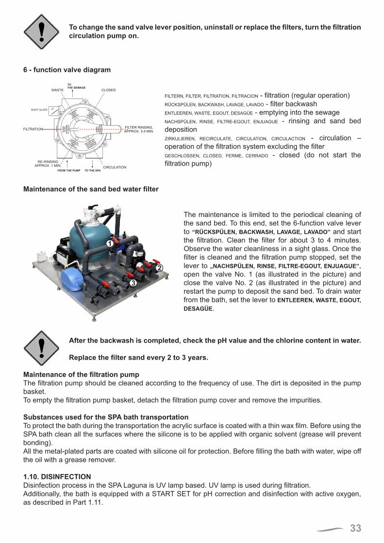
6 - function valve diagram
FROM THE PUMP TO THE SPA
TOTHE SEWAGE
CLOSEDWASTE
FILTER RINSING,
APPROX. 3-4 MIN.FILTRATION
CIRCULATION
RE-RINSING
APPROX. 1 MIN.
SIGHT GLASS
FIL
TE
RN
FIL
TE
RF
ILT
RA
TIO
NF
ILT
RA
CIO
N
ENTLEEREN
WASTE
EGOUT
DESAGÜE
GESCHLOSSEN
CLOSEDFERME
CERRADO
RÜ
CK
SP
ÜL
EN
BA
CK
WA
SH
LA
VA
GE
LA
VA
DO
ZIRKULIEREN
RECIRCULATE
CIRCULATION
CIRCULACTION
NACHSPÜLENRIN
SE
FILTRE-EGOUT
ENJUAGUE
FILTERN, FILTER, FILTRATION, FILTRACION - filtration (regular operation)RÜCKSPÜLEN, BACKWASH, LAVAGE, LAVADO - filter backwash ENTLEEREN, WASTE, EGOUT, DESAGÜE - emptying into the sewage NACHSPÜLEN, RINSE, FILTRE-EGOUT, ENJUAGUE - rinsing and sand bed deposition ZIRKULIEREN, RECIRCULATE, CIRCULATION, CIRCULACTION - circulation – operation of the filtration system excluding the filter GESCHLOSSEN, CLOSED, FERME, CERRADO - closed (do not start the filtration pump)
Maintenance of the sand bed water filter
1
2
3
The maintenance is limited to the periodical cleaning of the sand bed. To this end, set the 6-function valve lever to “RÜCKSPÜLEN, BACKWASH, LAVAGE, LAVADO” and start the filtration. Clean the filter for about 3 to 4 minutes. Observe the water cleanliness in a sight glass. Once the filter is cleaned and the filtration pump stopped, set the lever to „NACHSPÜLEN, RINSE, FILTRE-EGOUT, ENJUAGUE”, open the valve No. 1 (as illustrated in the picture) and close the valve No. 2 (as illustrated in the picture) and restart the pump to deposit the sand bed. To drain water from the bath, set the lever to ENTLEEREN, WASTE, EGOUT, DESAGÜE.
After the backwash is completed, check the pH value and the chlorine content in water.
Replace the filter sand every 2 to 3 years.
Maintenance of the filtration pumpThe filtration pump should be cleaned according to the frequency of use. The dirt is deposited in the pump basket. To empty the filtration pump basket, detach the filtration pump cover and remove the impurities.
Substances used for the SPA bath transportationTo protect the bath during the transportation the acrylic surface is coated with a thin wax film. Before using the SPA bath clean all the surfaces where the silicone is to be applied with organic solvent (grease will prevent bonding).All the metal-plated parts are coated with silicone oil for protection. Before filling the bath with water, wipe off the oil with a grease remover.
1.10. DISINFECTION Disinfection process in the SPA Laguna is UV lamp based. UV lamp is used during filtration.Additionally, the bath is equipped with a START SET for pH correction and disinfection with active oxygen, as described in Part 1.11.
34
1.11. MEASUREMENT AND TREATMENT FORMULA SET
Before the first bath and always once in 2 weeks, please check the water pH with the enclosed Dinofresh/pH Tester!!!
pH measurement:• rinse a test container and fill to the 10 ml mark with pool water,• add 1 PHENOLRED tablet to the container and close the plug,• shake the container and dissolve the tablet,• compare the test water colour with the colours in the column on the left and read the pH of the water sample,• all pH values below 6,8 make the water turn yellow,• all pH values above 8,2 make the water turn red,• ideal values range from 7,2 to 7,6.
Dinofresh measurement: This is a measurement of the active oxygen concentration contents, informing about the oxygen content level in water.• rinse a test container and fill to the 10 ml mark with pool water.• add 1 DPD no 4 tablet to the container and close the plug.• shake the container and dissolve the tablet.• compare the colour of the solution with the colours in the column on the right to read the Dinofresh value of the water sample.• the recommended values range from 5,0 to 8,0 mg/litre.
Important instructions:• do not touch the tablets! It may distort the test outcome,• reading of results must take place immediately after the tablet has dissolved in water,• after each measurement the test container and its lid should be thoroughly rinsed. Otherwise, it may also distort the results.
The tablet reagents are provided for the purpose of the above described chemical analyses and should not be used for any other purposes. The tablet reagents must not be handled by children.
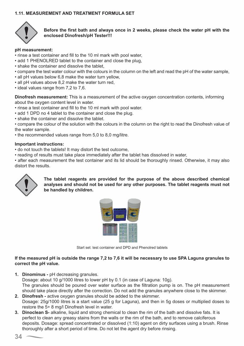
Start set: test container and DPD and Phenolred tablets
If the measured pH is outside the range 7,2 to 7,6 it will be necessary to use SPA Laguna granules to correct the pH value.
1. Dinominus - pH decreasing granules.Dosage: about 10 g/1000 litres to lower pH by 0.1 (in case of Laguna: 10g).The granules should be poured over water surface as the filtration pump is on. The pH measurement should take place directly after the correction. Do not add the granules anywhere close to the skimmer.
2. Dinofresh - active oxygen granules should be added to the skimmer.Dosage: 25g/1000 litres is a start value (25 g for Laguna), and then in 5g doses or multiplied doses to restore the 5÷ 8 mg/l Dinofresh level in water.
3. Dinoclean S- alkaline, liquid and strong chemical to clean the rim of the bath and dissolve fats. It is perfect to clean any greasy stains from the walls or the rim of the bath, and to remove calciferous deposits. Dosage: spread concentrated or dissolved (1:10) agent on dirty surfaces using a brush. Rinse thoroughly after a short period of time. Do not let the agent dry before rinsing.
35
A set of disinfecting agents for SPA LAGUNA can be purchased at most showrooms where POOL-SPA products are offered in the country.
It is a natural phenomenon that in SPA baths the pH value of water tends to increase. However, very rarely the pH value decrease can be observed. It is then recommended to use Dinoplus granules, which can be ordered through the showroom of the Laguna SPA manufacturer.
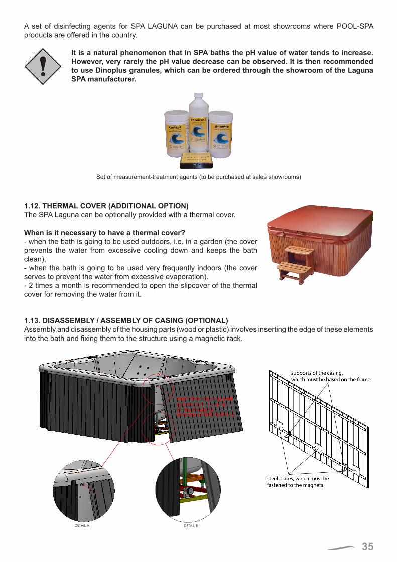
Set of measurement-treatment agents (to be purchased at sales showrooms)
1.12. THERMAL COVER (ADDITIONAL OPTION)The SPA Laguna can be optionally provided with a thermal cover.
When is it necessary to have a thermal cover?- when the bath is going to be used outdoors, i.e. in a garden (the cover prevents the water from excessive cooling down and keeps the bath clean),- when the bath is going to be used very frequently indoors (the cover serves to prevent the water from excessive evaporation).- 2 times a month is recommended to open the slipcover of the thermal cover for removing the water from it.
1.13. DISASSEMBLY / ASSEMBLY OF CASING (OPTIONAL)Assembly and disassembly of the housing parts (wood or plastic) involves inserting the edge of these elements into the bath and fixing them to the structure using a magnetic rack.
Insert the housing part between the support of the housing and rim of the bathtub
DETAIL BDETAIL A
.

36
PART 2 – INSTALLATION MANUAL2.1. SAFETY RULESSPA bath will be supplied to the customer in an original packaging. Remove the packaging and carefully check the SPA bath before use. Notify your dealer about noticed discrepancies, if any.
It is prohibited to lift the bath and the filtering units by the piping.Always put the bath on the feet. Do not let it rest on the side wall.Make sure that the bath is properly secured if the installation work is carried out in the close vicinity.
Connection of the electrical system to the network and connection of the fittings to the water line should be carried out by authorized professionals.
2.2. PREPARATION OF THE INSTALLATION SITE- The SPA bath can be used both in closed or open rooms.
- It should be placed on a hard, levelled floor to prevent the device from sinking and ensure proper operation.
- If the SPA bath is to be located in a closed room, make sure that enough space is provided to move the bath into the room.
- The dimensions of the bed plate the SPA bath is to be installed on should allow the installer to properly arrange the feet, conduits and cables (including sufficient access).
- Bear in mind the SPA bath emptying method.
- Pay attention to the material of the walls and the ceiling as they should be resistant to water steam produced during the SPA bath operation.
- In view of possible water splashing during the use of the SPA bath, the floor has to be made of a highly water resistant material such as tiles or plastic coats. Where a floor covering is used, it has to be adequately protected from bacteria which may develop in a moist environment. Use special rugs or coverings used in yachting. Parquet floors or any other wooden floors are nor recommended unless they have been appropriately processed as in the case of wood used in gardening or outdoor structures.
2.3. INSTALLATION OF THE BATH AND THE ADDITIONAL ACCESSORIES - To ensure proper operation of the SPA bath, install it on a firm and carefully levelled floor (providing for the drain slope), e.g. on a 10 cm thick cement slab to prevent the bath from sinking.
- Once the bath height is defined, prepare a cement block to rest the feet.
- The dimensions of the hollow and the cement block must be sufficient for the installer to properly arrange the feet, piping and the cables.
- Fasten the feet to the cement block so that they cannot move by accident.
- All the connections between the optional equipment and the bath have to be made by gluing the pipes and the fittings. Metal pipes must not be used.
- Fill the bath with water to make sure the connections are tight.
- Do not fill the hollow around the bath with any materials as the access to all the pipes and connection points has to be maintained.
37
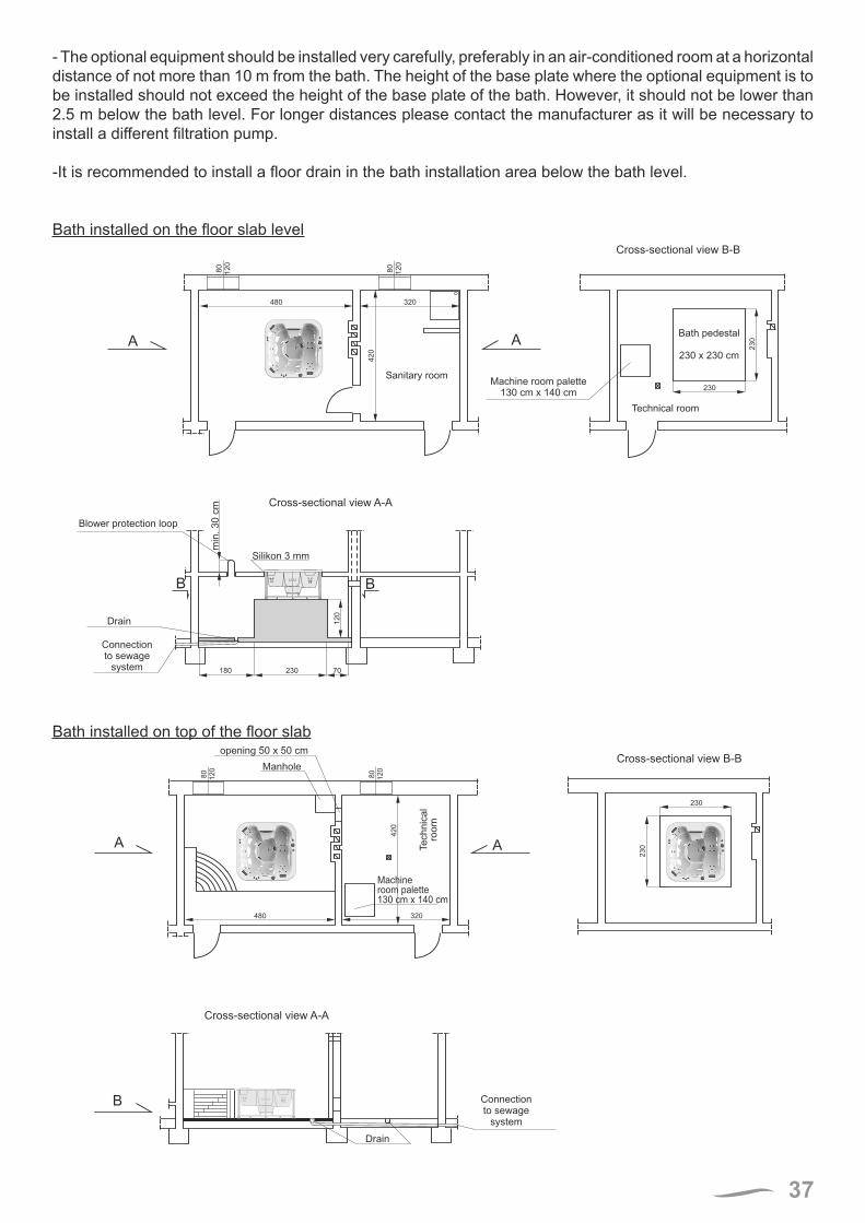
- The optional equipment should be installed very carefully, preferably in an air-conditioned room at a horizontal distance of not more than 10 m from the bath. The height of the base plate where the optional equipment is to be installed should not exceed the height of the base plate of the bath. However, it should not be lower than 2.5 m below the bath level. For longer distances please contact the manufacturer as it will be necessary to install a different filtration pump.
-It is recommended to install a floor drain in the bath installation area below the bath level.
Bath installed on the floor slab level8
0
12
0
80
12
0
480 320
42
0
A A
230
23
0
B
Silikon 3 mm
min
. 3
0 c
m
B
12
0
180 230 70
Sanitary roomMachine room palette
130 cm x 140 cm
Technical room
Bath pedestal
230 x 230 cm
Cross-sectional view B-B
Cross-sectional view A-A
Blower protection loop
Drain
Connection
to sewage
system
Bath installed on top of the floor slab
80
12
0
80
12
0
480 320
42
0
AA
B
230
23
0Te
ch
nic
al
roo
m
Machine
room palette
130 cm x 140 cm
opening 50 x 50 cm
Manhole
Connection
to sewage
system
Cross-sectional view B-B
Cross-sectional view A-A
Drain
38
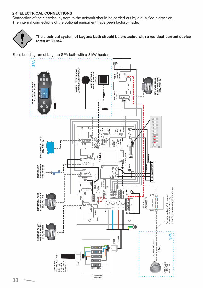
2.4. ELECTRICAL CONNECTIONSConnection of the electrical system to the network should be carried out by a qualified electrician.The internal connections of the optional equipment have been factory-made.
The electrical system of Laguna bath should be protected with a residual-current device rated at 30 mA.
Electrical diagram of Laguna SPA bath with a 3 kW heater.
VA
RIO
BO
X
(PE
6000011)
PE
60
00
06
4
PG7
PG7
LA
MP
ALE
D
12V
AC
PE
4000042
Prz
ew
ód 2
x0,5
mb
OZ
ON
E L
AM
PL
AM
PA
OZ
ON
U2
30
VA
C 5
0H
z
MA
SS
AG
E P
UM
P1
PO
MP
AM
AS
AŻ
U 1
23
0V
AC
50
Hz
DM
UC
HA
WA
/BL
OW
ER
23
0V
AC
50
Hz
LE
D
WA
TE
R L
EV
EL
SE
NS
OR
CZ
UJ
NIK
PO
ZIO
MU
WO
DY
Wi-
Fi
RE
CE
IVE
RO
DB
IOR
NIK
Wi-
Fi
(OP
CJ
A)
MA
IN C
ON
TR
OL
PA
NE
LG
ŁÓ
WN
YP
UL
PIT
L1 L2 N PE
L1 L2 N PE
L1 L2 N PE
L1 L2 N PE
L1 L2 N PE
FIL
TR
AT
ION
PU
MP
PO
MP
AF
ILT
RA
CJ
I2
30
VA
C 5
0H
z
VARIOBOX(PE6000011)
5x4
mm
2
L1
L2
L3
PE
N
PE6000064
PG
21
PG
21 S
PA
L1 L2 N PE
MA
SS
AG
E P
UM
P2
PO
MP
AM
AS
AŻ
U 2
23
0V
AC
50
Hz
ZA
SIL
AN
IE3N
400V
AC
50H
z
5x4m
m2
L1 -
13
AL
2 -
6,7
AL
3 -
13,6
5A
Prz
ew
ód p
odłą
czyć
do lam
py,
końców
ki zaro
bić
tule
jkam
i,prz
ew
ód p
rzypom
ocow
ać
pod w
ann
ą
10
mb
SP
A
39
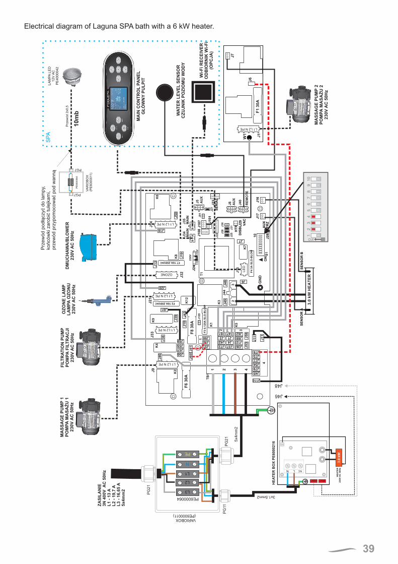
Electrical diagram of Laguna SPA bath with a 6 kW heater.
J101 J100
MA
SS
AG
E P
UM
P1
PO
MP
AM
AS
AŻ
U 1
230V
AC
50H
zD
MU
CH
AW
A/B
LO
WE
R230V
AC
50H
z
L1 L2 N PE
OZONE
LE
D
WA
TE
R L
EV
EL
SE
NS
OR
CZ
UJN
IK P
OZ
IOM
U W
OD
Y
Wi-
Fi R
EC
EIV
ER
OD
BIO
RN
IK W
i-F
i(O
PC
JA
)
MA
IN C
ON
TR
OL
PA
NE
LG
ŁÓ
WN
YP
UL
PIT
HE
AT
ER
23
0V
AC
50
Hz
3.0
kW
N L NC
HE
AT
ER
BO
XP
E6000216
VARIOBOX
(PE6000011)
3x1.5mm2
5x4
mm
2
L1
L2
L3
PE
N
PE6000064
PG
21
PG
11
PG
21
J46
J48
L1 L2 N PE
L1 L2 N PE
L1 L2 N PE
VA
RIO
BO
X(P
E6000011)
PE
60
00
06
4
PG7
PG7
LA
MP
ALE
D12V
AC
PE
4000042
Prz
ew
ód 2
x0,5
SP
A
FIL
TR
AT
ION
PU
MP
PO
MP
AF
ILT
RA
CJI
230V
AC
50H
z
OZ
ON
E L
AM
PL
AM
PA
OZ
ON
U230V
AC
50H
z
ZA
SIL
AN
IE3N
400V
AC
50H
z
5x4m
m2
L1 -
13
AL
2 -
19,7
AL
3 -
16,6
5A
MA
SS
AG
E P
UM
P2
PO
MP
AM
AS
AŻ
U 2
230V
AC
50H
z
L1 L2 N PE
Prz
ew
ód
po
dłą
czyć
do
la
mp
y,ko
ńcó
wki za
rob
ićtu
lejk
am
i,p
rze
wó
d p
rzyp
om
oco
wa
ćp
od
wa
nn
ą
10
mb
40
2.4.1. Earthing and equalizer connectionTo ensure proper functioning of the residual-current device, the building needs to be equipped with an earthed system and an equalizer connection complying with the applicable regulations.
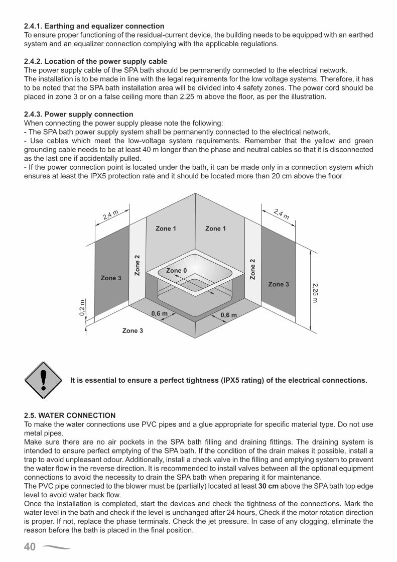
2.4.2. Location of the power supply cableThe power supply cable of the SPA bath should be permanently connected to the electrical network.The installation is to be made in line with the legal requirements for the low voltage systems. Therefore, it has to be noted that the SPA bath installation area will be divided into 4 safety zones. The power cord should be placed in zone 3 or on a false ceiling more than 2.25 m above the floor, as per the illustration.
2.4.3. Power supply connectionWhen connecting the power supply please note the following:- The SPA bath power supply system shall be permanently connected to the electrical network.- Use cables which meet the low-voltage system requirements. Remember that the yellow and green grounding cable needs to be at least 40 m longer than the phase and neutral cables so that it is disconnected as the last one if accidentally pulled.- If the power connection point is located under the bath, it can be made only in a connection system which ensures at least the IPX5 protection rate and it should be located more than 20 cm above the floor.
2,4m
2,4 m
Zone 1 Zone 1
Zone 0
Zone 3Zone 3
Zone 3
Zo
ne
2
Zo
ne
2
2,2
5m
0,6 m 0,6 m0,2
m
It is essential to ensure a perfect tightness (IPX5 rating) of the electrical connections.
2.5. WATER CONNECTIONTo make the water connections use PVC pipes and a glue appropriate for specific material type. Do not use metal pipes.Make sure there are no air pockets in the SPA bath filling and draining fittings. The draining system is intended to ensure perfect emptying of the SPA bath. If the condition of the drain makes it possible, install a trap to avoid unpleasant odour. Additionally, install a check valve in the filling and emptying system to prevent the water flow in the reverse direction. It is recommended to install valves between all the optional equipment connections to avoid the necessity to drain the SPA bath when preparing it for maintenance.The PVC pipe connected to the blower must be (partially) located at least 30 cm above the SPA bath top edge level to avoid water back flow.Once the installation is completed, start the devices and check the tightness of the connections. Mark the water level in the bath and check if the level is unchanged after 24 hours, Check if the motor rotation direction is proper. If not, replace the phase terminals. Check the jet pressure. In case of any clogging, eliminate the reason before the bath is placed in the final position.
41
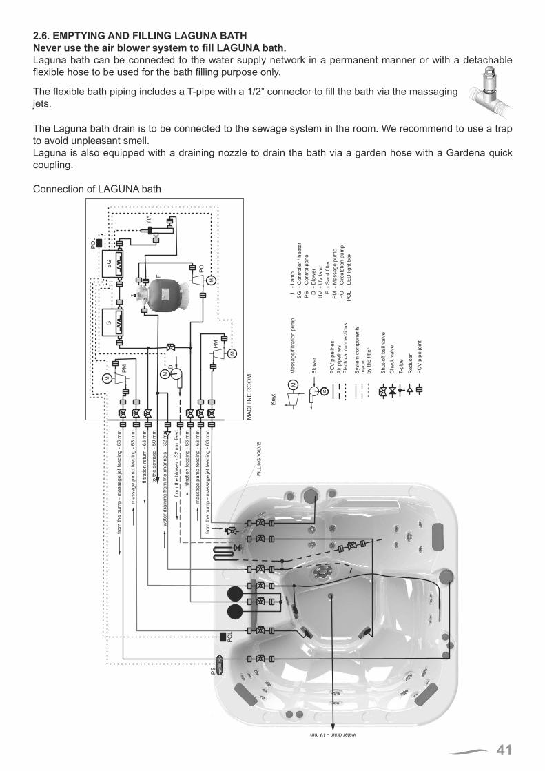
2.6. EMPTYING AND FILLING LAGUNA BATHNever use the air blower system to fill LAGUNA bath.Laguna bath can be connected to the water supply network in a permanent manner or with a detachable flexible hose to be used for the bath filling purpose only.
The flexible bath piping includes a T-pipe with a 1/2” connector to fill the bath via the massaging jets.
The Laguna bath drain is to be connected to the sewage system in the room. We recommend to use a trap to avoid unpleasant smell.Laguna is also equipped with a draining nozzle to drain the bath via a garden hose with a Gardena quick coupling.
Connection of LAGUNA bath
M
M
PO
PM
F
M
D
GS
G
filtra
tio
n f
ee
din
g -
63
mm
fro
m t
he
pu
mp
- m
assa
ge
je
t fe
ed
ing
- 6
3 m
m
ma
ssa
ge
pu
mp
fe
ed
ing
- 6
3 m
m
wa
ter
dra
inin
g f
rom
th
e c
ha
nn
els
-
32
mm
filtra
tio
n r
etu
rn -
63
mm
fro
m t
he
blo
we
r -
32
mm
fe
ed
to t
he
se
wa
ge
- 5
0 m
m
VU
PS
M
PM
ma
ssa
ge
pu
mp
fe
ed
ing
- 6
3 m
m
fro
m t
he
pu
mp
- m
assa
ge
je
t fe
ed
ing
- 6
3 m
m
PO
L
PO
L
T-p
ipe
Re
du
ce
r
Ch
eck v
alv
e
Sh
ut-
off b
all v
alv
e
Ele
ctr
ica
l co
nn
ectio
ns
Air p
ipe
lin
es
PC
V p
ipe
lin
es
PC
V p
ipe
jo
int
MM
assa
ge
/filtr
atio
n p
um
p
M
Blo
we
r
Key:
Syste
m c
om
po
ne
nts
ma
de
by t
he
fitte
r
L
SG
PS D
UV F
PM
PO
PO
L
- L
am
p
- C
on
tro
lle
r /
he
ate
r
- C
on
tro
l p
an
el
- B
low
er
- U
V la
mp
- S
an
d f
ilte
r
- M
assa
ge
pu
mp
- C
ircu
latio
n p
um
p
- L
ED
lig
ht
bo
x
MA
CH
INE
RO
OM
FIL
LIN
G V
ALV
E
water drain- 19 mm
42
WARRANTY TERMS1. ROCA POOL-SPA Sp. z o.o. with its registered office in Gliwice, ul. Wyczółkowskiego 20, provides a 24-month warranty for LAGUNA SPA bath described on the reverse and offers paid repair services beyond that period. Note: Halogen bulbs are excluded from this warranty.
2. The manufacturer provides a 7-year warranty for the colour and gloss of the acrylic surface provided that the maintenance instructions described herein are adhered to.
3. The installation of LAGUNA SPA bath is performed free-of-charge by authorized servicemen of ROCA POOL-SPA Sp. z o.o. Note: The same does not include the provision of water, sewage and electricity connection points and the surface preparation.
4. Any claims regarding the damage of the bath top resulting from the stress caused by the sunlight exposure with no thermal cover used will not be entertained by the manufacturer.
5. Any defects or damage to the product revealed during the warranty period and not attributable to the user will be repaired free of charge within 14 working days from the claim date. Any repairs shall be carried out at the Customer’s premises.
6. Any defects or damage noticed shall be reported to the product seller. If this is not possible, the Service Department of ROCA POOL-SPA should be notified in writing.
7. The warranty is considered null and void in case of:a. mechanical damage to the accessories,b. mechanical damage to the bath surface,c. repairs or modifications of the electronic control system carried out by the user,d. bath installation carried out in a way which prevents ventilation and easy access to all the devices installed under the bath,e. mounting other accessories on the bath frame or the bath basin,f. use of cleaning agents which are improper or not in line with the instructions.g. use of water which does not meet the parameters provided for in the Regulation of the Minister of Health and Social Care of 4 May 1990, Polish Journal of Laws No. 35.
8. This warranty shall be null and void if the sale of the LAGUNA SPA bath is not confirmed by the seller with a signature, seal and a date of sale in the warranty card included in the Polish version of this manual.
9. This warranty is valid if the connection to the electrical network is made by authorized servicemen of ROCA-POOL SPA (to be confirmed in the Warranty Card).
10. The manufacturer shall not reimburse the cost of replacing any damaged housing including tiles if the same need to be removed to enable the carry out the warranty repair.
11. The customer shall be charged with any costs of verification of an unjustified warranty claim.
12. The warranty for consumer goods does not exclude, limit or cancel the buyer’s rights related to discrepancies between the product purchased and the contract.
13. The warranty is valid in the Republic of Poland.
ROCA POOL-SPA Sp. z o.o.ul. Wyczółkowskiego 20, 44-109 Gliwice
tel. + 48 32 339 41 00www.roca.pl, e-mail: [email protected]
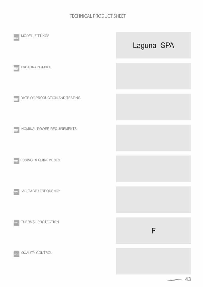
43
MODEL, FITTINGS
FACTORY NUMBER
DATE OF PRODUCTION AND TESTING
TECHNICAL PRODUCT SHEET
NOMINAL POWER REQUIREMENTS
FUSING REQUIREMENTS
VOLTAGE / FREQUENCY
F
Laguna SPA
THERMAL PROTECTION
QUALITY CONTROL
ROCA POOL-SPA company has the policy of constant improvement of products and reserves the right to introduce changes to the specification and colours without a prior notification. However, ROCA POOL-SPA makes all efforts to ensure that the specifications are updated on the date of publishing.
09.06.2015171ZPI3000306
ROCA POOL-SPA Sp. z o.o.ul. Wyczółkowskiego 20,
44-109 Gliwicetel. + 48 32 339 41 00
www.roca.pl, e-mail: [email protected]