SP400 Electropneumatic Smart Positioner - Spirax Sarco · The SP400 smart valve positioner is loop...
44
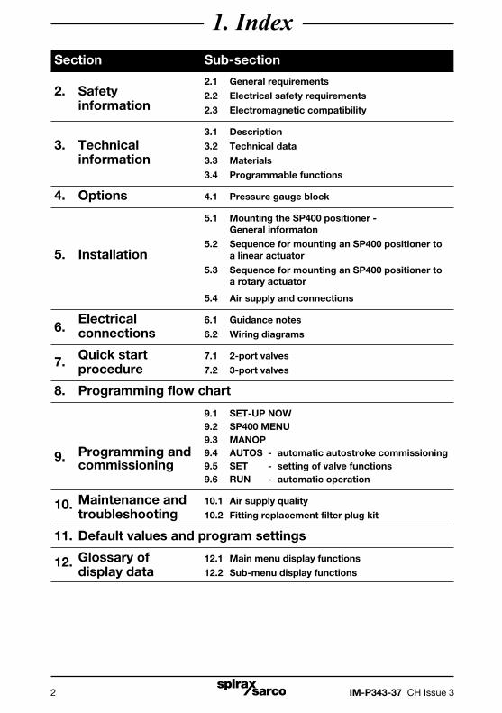
SP400 Electropneumatic Smart Positioner Installation and Maintenance Instructions IM-P343-37 CH Issue 3 3.568.5275.400 1. Index 2. Safety information 3. Technical information 4. Options 5. Installation 6. Electrical connections 7. Quick start procedure 8. Programming flow chart 9. Programming and commissioning 10. Maintenance 11. Default values and program settings 12. Glossary of display data Printed in Italy © Copyright 2011
Transcript of SP400 Electropneumatic Smart Positioner - Spirax Sarco · The SP400 smart valve positioner is loop...

IM-P343-37 CH Issue 3 1
SP400 Electropneumatic Smart Positioner
Installation and Maintenance Instructions
IM-P343-37CH Issue 3
3.568.5275.400
1. Index2. Safety information3. Technical information4. Options5. Installation6. Electrical connections7. Quick start procedure8. Programming flow chart9. Programming and commissioning10. Maintenance11. Default values and program settings12. Glossary of display data
Printed in Italy © Copyright 2011
IM-P343-37 CH Issue 32
1. IndexSection Sub-section
2.1 General requirements2. Safety 2.2 Electrical safety requirements
information 2.3 Electromagnetic compatibility
3.1 Description
3. Technical 3.2 Technical data
information 3.3 Materials
3.4 Programmable functions
4. Options 4.1 Pressure gauge block
5.1 Mounting the SP400 positioner - General informaton
5.2 Sequence for mounting an SP400 positioner to5. Installation a linear actuator
5.3 Sequence for mounting an SP400 positioner to a rotary actuator
5.4 Air supply and connections
6. Electrical 6.1 Guidance notes
connections 6.2 Wiring diagrams
7. Quick start 7.1 2-port valves
procedure 7.2 3-port valves
8. Programming flow chart
9.1 SET-UP NOW 9.2 SP400 MENU 9.3 MANOP
9. Programming and 9.4 AUTOS - automatic autostroke commissioning commissioning 9.5 SET - setting of valve functions 9.6 RUN - automatic operation
10. Maintenance and 10.1 Air supply quality
troubleshooting 10.2 Fitting replacement filter plug kit
11. Default values and program settings
12. Glossary of 12.1 Main menu display functions
display data 12.2 Sub-menu display functions

IM-P343-37 CH Issue 3 3
2. Safety information2.1 General requirementsThe flawless and safe operation of the SP400 positioners is reliant on proper transportation, storage, installation and commissioning by qualified personnel, proper use and careful maintenance.
Prior to installing, using or maintaining the positioner, consideration should be given to:
- The working environment.
- Safe access.
- Lighting.
- Pipeline fluid hazards.
- Temperature.
- System isolation.
- Location.
The SP400 positioner should be mounted with sufficient space to allow opening of the hinged cover and to provide access for electrical and air connections. When fitting to an actuator, ensure that the positioner will not be exposed to an ambient temperature outside the range of -10°C to +80°C. The positioner enclosure is rated to IP65 (see BS EN 60534-1 1998).
2.2 Electrical safety requirementsThe SP400 is a class III product which must only be powered from Safe Extra Low Voltage (SELV) sources whether by virtue of a 4 - 20 mA control signal or from a separate power supply. Similarly all signal circuits connected to an options board must operate within the confines of SELV systems. All associated wiring must be separated from other wiring containing hazardous voltages.
2.3 Electromagnetic compatibilityThe product complies with the Electromagnetic Compatibility Directive 2004 / 108 / EC according to:- EN 61326-1: 2006- EN 61326-2-3: 2006- EN 55011: 1998 + A1: 1999 + A2: 2002- EN 61000-4-2: 1995 + A1: 1998 + A2: 2001- EN 61000-4-3: 2006- EN 61000-4-4: 2004- EN 61000-4-5: 2006- EN 61000-4-6: 2007- EN 61000-4-11: 2004This product may be affected by interference if:
- The product or its wiring is located near a radio transmitter. The actual separation necessary will vary according to the power of the transmitter.
- Cellular telephones or mobile radios are used within approximately one metre of the product or its wiring.
- The wiring is routed alongside power cables subject to high voltage transients or current surges.

IM-P343-37 CH Issue 34
3. Technical information3.1 DescriptionThe SP400 smart valve positioner is loop powered from a 4 - 20 mA input signal to provide accurate adaptive positional control of pneumatic actuated linear and quarter turn valves.Precise control is maintained through valve position feedback that automatically varies the pneumatic output pressure to overcome the effects of stem friction and flow forces to maintain desired valve position. Indication of valve position is provided through a continuous digital display of % travel. Valve position feedback is retrieved by means of a non contact technology based on Hall effect. The pneumatics are based on piezovalve technology - Therefore, high resolution, high reliability, vibration insensitivity and extremely low air consumption is guaranteed at steady state.The SP400 includes many smart functions that can be fully programmed through menu driven software using an integral keypad and LCD alphanumeric data. The absence of mechanical linkages between valve stem and positioner, drastically simplifies the mounting procedure and reduces the time required. Moreover the software has been designed to simplify operations as much as possible: commissioning requires just assembling the SP400 to the valve and pressing one button. The SP400 is supplied with a NAMUR standard mounting kit for attachment to yoke or pillar mounted actuators. For quarter turn valves, a mounting kit compliant to VDI / VDE 3845 is supplied.
Fig. 1
12
No. Part
1. LCD display
2. Main menu functions with LCD flag indication
3. Signal pressure to actuator
4. Gland connection for wiring M20
5. Terminal block
6. Increase value or toggle value key
7. Decrease value or toggle value key
8. Enter key
9. Supply pressure to positioner
10. Optional pressure gauge block with gauges
11. Spare M20 gland connection for wiring a 4-20 mA retransmission or software switches
12. External earth
13. Internal earth
4
11
10
9
3
21
13 5 6 7 8
IM-P343-37 CH Issue 3 5
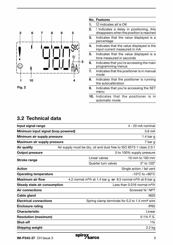
No. Features 1. indicates all is OK 2. ! Indicates a delay in positioning, this
disappears when the position is reached 3. Indicates that the value displayed is a
percentage 4. Indicates that the value displayed is the
input current measured in mA 5. Indicates that the value displayed is a
time measured in seconds 6. Indicates that you're accessing the main
programming menus 7. Indicates that the positioner is in manual
mode 8. Indicates that the positioner is running
the autocalibration 9. Indicates that you're accessing the SET
menu 10. Indicates that the positioner is in
automatic mode
10
6 7 8 9 5
Fig. 2
3.2 Technical dataInput signal range 4 - 20 mA nominal
Minimum input signal (loop powered) 3.6 mA
Minimum air supply pressure 1.4 bar g
Maximum air supply pressure 7 bar g
Air quality Air supply must be dry, oil and dust free to ISO 8573-1 class 2:3:1
Output pressure 0 to 100% supply pressure
Stroke range Linear valves 10 mm to 100 mm
Quarter turn valves 5° to 120°
Action Single action / fail vent
Operating temperature -10°C to +80°C
Maximum air flow 4.2 normal m3/h at 1.4 bar g or 8.5 normal m3/h at 6 bar g
Steady state air consumption Less than 0.016 normal m3/h
Air connections Screwed ¼" NPT
Cable gland M20
Electrical connections Spring clamp terminals for 0.2 to 1.5 mm² wire
Enclosure rating IP65
Characteristic Linear
Resolution (maximum) 0.1% F.S.
Shut-off 1%
Shipping weight 2.2 kg
2
1 4
3

IM-P343-37 CH Issue 36
3.3 MaterialsPart Material Finish
Case and cover Die cast aluminium Anti-corrosive paint to RAL5010
Magnet bracket Die cast aluminium
3.4 Programmable functionsAutostroke Automatic commissioning routine
Valve type 2-port or 3-port
% travel Selectable 0 to 100% or 100% to 0%
depending on valve / actuator configuration
Control action Direct or reverse action (4 - 20 or 20 - 4 mA)
OFF range 4-20 mA
Split range LOW range 4-13 mA
HIGH range 11-20 mA
0.5%
Deadband 1.5%
3.0%
5.0%
Reset Resets all programmed values to default settings
Input signal Visualisation of input mA signal

IM-P343-37 CH Issue 3 7
4. Options4.1 Pressure gauge blockAn optional pressure gauge block (Figure 3) can be fitted onto the SP400 positioner which includes two pressure gauges indicating air supply pressure and output air signal pressure to the actuator. The pressure gauge block can be retrospectively fitted using 2 off M5 socket head screws. Ensure that the gauge block air connection 'O' rings are correctly located before tightening.
Fig. 3

IM-P343-37 CH Issue 38
5. Installation5.1 Mounting the SP400 positioner - General informationPreliminary check of valve and actuator assembly - A preliminary check should be carried out on the valve and actuator assembly prior to mounting and commissioning the SP400 positioner to confirm smooth movement of the stem. This can be performed by providing an air supply directly from a filter/regulator to the actuator. The air supply pressure should be gradually increased to progressively move the stem through its full travel. Any friction or jerky movement of the stem should be investigated prior to commissioning the SP400.
5.1.1 The SP400 is supplied with a NAMUR standard fixing kit for linear actuators (yoke or pillar) or with a VDI / VDE 3845 compliant mounting kit for rotary actuators.
5.1.2 The SP400 has an enclosure rating of IP65 and should be installed in a location that will not exceed its ambient temperature limits of -10°C minimum and +80°C maximum.
5.1.3 Before fitting and commissioning the SP400 positioner ensure that the valve and actuator are correctly assembled. Refer to the valve and actuator Installation and Maintenance Instructions for details.
IM-P343-37 CH Issue 3 9
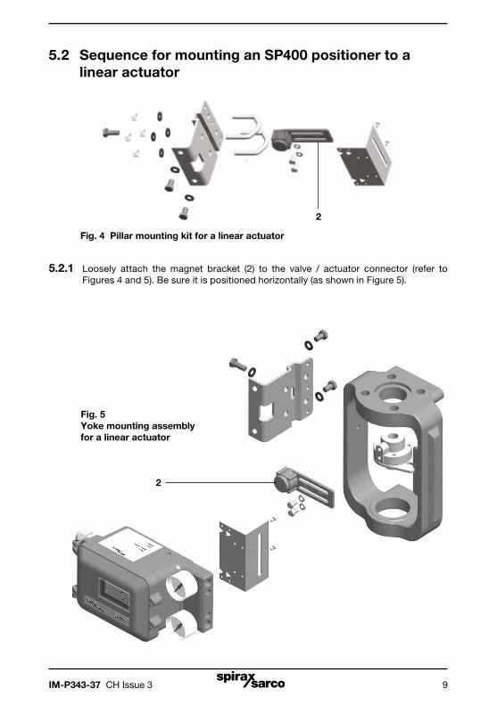
5.2.1 Loosely attach the magnet bracket (2) to the valve / actuator connector (refer to Figures 4 and 5). Be sure it is positioned horizontally (as shown in Figure 5).
Fig. 4 Pillar mounting kit for a linear actuator
Fig. 5Yoke mounting assembly for a linear actuator
5.2 Sequence for mounting an SP400 positioner to a linear actuator
2
2

IM-P343-37 CH Issue 310
5.2.2 Slide the bracket (2) to the left or to the right (Figure 6) till the correct position is achieved. If you’re using a Spirax Sarco actuator the correct position is impressed on the magnet bracket (Figure 7).
5.2.3 If you’re not using a Spirax Sarco actuator, slide the bracket till the distance 'A' between the center of the magnet and the inner side of the mounting plate is 25 mm (Figure 8).
Fig. 8 A Distance between the mounting plate and magnet
Fig. 7 Bracket markings
Fig. 6
Assembled
2
Mounting plate
Bracket
Centerof the
magnet
PN1000PN9000

IM-P343-37 CH Issue 3 11
Bracket
5.2.4 Loosely attach the positioner mounting plate to the actuator as shown in the following pictures: for the pillar actuator (Figure 9), and for the yoke actuator (Figure 10).
Fig. 9 Pillar actuator assembly
Pillar actuatorMounting plate
Fig.10 Yoke actuator assemblyYoke actuator
Mounting plate
5.2.5 Locate the protection plate onto the back of the SP400 positioner housing and fix in place (Figures 11 and 12).
Protection plate
Fig. 11
Assembled
Assembled
Assembled
Fig. 12

IM-P343-37 CH Issue 312
5.2.6 Attach the positioner mounting plate to the positioner as shown in Figures 26 and 27.
Protection plate
5
Fig. 13
Attach the mounting
plate
Assembled
Fig. 14
5.2.7Adjust the vertical position of the SP400 positioner and mounting plate assembly, by sliding it up or down on the pillar style actuators, ensuring that the positioner is roughly centred on the actuator / valve stroke (Figure 10).
Even if this is the ideal condition, it’s not mandatory. In fact, as shown in Figure 15, the only necessary condition for correct operation is that the stroke of the magnet (dimension B) lay inside the sensor operating linear range (dimension A), i.e. the vertical dimension marked on the case of the positioner.
B
A
Fig. 15
SP400 positoner
5.2.8When the SP400 positioner and mounting plate assembly is correctly positioned, tighten the hexagon headed screw (5) on the yoke mounted actuator (Figure 13) to 10 - 12 N m and tighten the 'U'bolt nuts (6) on the pillar mounted actuators (Figure 16) to 10 - 12 N m.
6
Fig. 16

IM-P343-37 CH Issue 3 13
5.3 Sequence for mounting an SP400 positioner to a rotary actuator
5.3.1 Assembly for fitting an SP400 on to a ¼ turn valve.
Fig. 17 Mounting kit

IM-P343-37 CH Issue 314
Fig. 18
Fig. 20
Fig. 19

IM-P343-37 CH Issue 3 15
Fig. 21
Fig. 22
Assembled

IM-P343-37 CH Issue 316
5.3.2 Adjust the magnet orientation as illustrated in Figures 23 and 24 and tighten the bolt to fix the magnet into position. There should be a distance of between 5 and 14 mm between the magnet and the positioner.
Refer to Figure 23 for actuator with clockwise rotation. Refer to Figure 24 for actuator with anti-clockwise rotation. In fact, in this way the magnet movements will always be comprised in the sector between
the directions C and D which delimit the operating area of the Hall sensor.
Fig. 23 View from the bottom of the positioner - Magnet orientation for clockwise actuator.
Fig. 24 View from bottom of the positioner - Magnet orientation for anti-clockwise actuator.
DB
A
C
15°
90°
120°
15°
DB
A
C
15°
90°
120°
15°

IM-P343-37 CH Issue 3 17
Fig. 25
¼" NPT air supply (supply)
¼" NPT air signal to actuator (output 1)
5.4 Air supply and connectionsWARNING: Supply air pressure must not exceed the maximum allowable air pressure of the actuator. Air connections should be ¼" NPT for air supply (supply) and output signal to actuator (Figure 25). The supply air should be between 1.4 bar g minimum and 6 bar g maximum and be oil and dust free to IEC 60770. Mains air supply may sometimes contain traces of dirt, rust, water, oil and other deposits with the potential for contaminating the internals of the positioner. It is therefore essential that a filter / regulator is fitted in the mains air supply to the positioner. The filter / regulator should have a coalescing filter such as a Spirax Sarco type MPC2, or suitable compressed air pipework is used.

IM-P343-37 CH Issue 318
6. Electrical connections6.1 Guidance notes on wiring installationFor heavy industrial applications it is recommended to use screened cables or signal cables run in metal conduit. Failure to do so could result in positional errors of up to ±5% in an RF field excess of 10 V/m. If screened cables are used, ensure that the screen is connected to the local earth at one end with a connection resistance of less than 1 ohm.
For light industrial applications where RF fields do not exceed 3 V/m unscreened cables may be used.
Cabling should be installed in accordance with BS 6739 - Instrumentation in Process Control Systems: Installation design and practice or local equivalent.
6.2 Wiring diagrams6.2.1 Terminal block
No. Pole Description
1 +Not used
2 -
3 +4-20 mA current signal input Mainboard
4 -
5 +Not used
6 -
7 +Not used
8 -
9 +Not used
10 -
Fig. 26
SP400
AUTOMATIC TUNE
50 %
SETAUTOSMANUALMENU
-
+4-
20m
A
1
2
3
4
5
6
7
8
9
10
�
�
AUTOSTROKEkeep pressed

IM-P343-37 CH Issue 3 19
6.2.3 Multi-loop applications Loop powered multi-positioner connections
4 - 20 mA signal +@ 14 V minimum -
In a loop powered application, the 4-20 mA signal must be capable of supplying a minimum of 7 V per positioner at 20 mA. In a split range application the signal source must be capable of supplying sufficient voltage, i.e. 14 V is enough to power 2 positioners.
Fig. 27
4 - 20 mA signal
3 4
+ -
3 4
Positioner 1
3 4
Positioner 2
Fig. 28
6.2.2 Single loop applications
The SP400 is loop powered using the 4 - 20 mA input signal source providing a minimum signal of 3.6 mA can be maintained.
Minimum current 3.6 mA
Maximum current 30 mA
Maximum voltage drop < 7 V
Overvoltage protection Up to 30 Vdc
Protection against polarity inversion Up to 30 Vdc

IM-P343-37 CH Issue 320
7. Quick start procedure7.1 2-port valvesThe following applies to positioners fitted to 2-port valves having plug above the seat and fitted to pneumatic actuators having a direct acting (DIR) 4 - 20 mA input signal and excludes the setting of any additional program functions (i.e. default value only).Note: For PN5100 and PN6100 series actuators an additional programming step is required. (Refer to Section 9.5.2).
7.1.1 The positioner should be correctly assembled as described in Section 5 and Section 6 and supplied with mains air and signal pipework as described in Section 5.4.
7.1.2 Provide a minimum input signal of 3.6 mA to the positioner. SET-UP NOW should be displayed.
7.1.3 Ensure that upstream isolation valves are closed. Press and hold the key for 3 seconds to advance to the SP400 MENU. The display will count down the 3 seconds.
7.1.4 Press the key to advance to MANOP.
7.1.5 Press and hold the key for 3 seconds to enter manual control mode MCTL.
7.1.6 In manual control press and hold the or key to drive the valve stem up or down. Check for any obstructions of valve movement. The display will indicate FILL or VENT as appropriate. Any obstruction should be investigated before proceeding to Section 7.1.7.
7.1.7 Press the key to return to MANOP in main menu.
7.1.8 Press and hold the key for 6 seconds to start the autostroke routine. This will take approximately 2 minutes to complete.
! displayed indicates an incomplete or unsuccessful autostroke.
The routine can be aborted at any time by pressing the key once.
If autostroke is aborted during operation ABORT will be displayed and ! to indicate incomplete autostroke.
On completion the program will automatically return to AUTOS in main menu.
A will be displayed if successful autostroke has been completed.
7.1.9 The valve will move to a control position related to the input control signal. The percentage valve travel will be displayed %. The positioner cover can now be closed and cover screws tightened.

IM-P343-37 CH Issue 3 21
7.2 3-port valves (with travel setting (TRAVL) 0 - 100%, refer to Figures 14 and 15)
Proceed as above up to Section 7.1.8.
7.2.1 On completion of a successful autostroke press and hold the key for 3 seconds to access the SP400 MENU.
7.2.2 Press the key three times to access SET.
7.2.3 Press the key once to advance to VALVE TYPE. Press the key to indicate VALVE 3-PORT.
7.2.4 Press the key to select VALVE 3-PORT. Continue to press the key to return to SET in the main menu.
7.2.5 Press the key twice to advance to RUN in the main menu.
7.2.6 Press and hold the key for 3 seconds to commence automatic operation. The valve will move to a control position related to the input control signal. The percentage travel will be displayed %. The positioner cover can now be closed and the cover screws tightened.

IM-P343-37 CH Issue 322
Autostroke activate(AUTOS)
Manual operation(MCTL)
8. Programming flow chart
Fig. 29
MANOP
AUTOS
SET
RUN
SET-UPNOW
SP400MENU
% Travel(TRAVL
0-100% / 100-0%)
Note: SET and RUN can only be accessed on completion of a successful autostroke (AUTOS)
From RETRNPSWRD
Softwareversion
(Ver X.XX)

IM-P343-37 CH Issue 3 23
mA INPUTAUTO OPERATION(% TRAVEL)
C-CAL
RETURN(To SP400 MENU)
Key
3 seconds enter
Enter
Auto returnClear stored
values(RESET)
Recall stored values
(RETRN)
Retain temporary values
(RTAIN)
VALVE CTRLA DBAND SPLIT RANGE

IM-P343-37 CH Issue 324
9. Programming and commissioning9.1 Set-up now
Programming notesThe positioner fitted to this control valve requires programming. A minimum input signal of 3.6 mA is required to power the positioner. To program the positioner it is necessary to enter the SP400 MENU and carry out an autostroke commissioning routine (AUTOS) prior to putting the control valve into automatic operation. A flow chart is included in Section 8 to guide you through the procedure. The display provides a flag indication of the active main menu function.To enter the SP400 MENU press and hold the key for 3 seconds. The display will count the 3 seconds.
Commissioning notesMain menu functions include:
SP400 MENU View software version, mounting position check, reset default values.
MANOP Manual control of valve movement (Actuator inflation / deflation).
AUTOS Automatic valve commissioning. Provides selection of % travel display.
SET Setting of valve type, control action, input signal span and deadband.
RUN Activates automatic operation plus input signal, total valve strokes and total run time. Also provides route for returning to the SP400 MENU.
Note: SET and RUN functions are restricted and can only be accessed on completion of a successful autostroke routine (AUTOS).
In order to make commissioning as fast and simple as possible, you can run the autocalibration routine directly from the following menus: SETUP NOW, SP400 MENU, MANOP, SET, RUN. Keep the key pressed for 6 seconds and the autostroke will start. At the end of the routine the positioner will enter into automatic mode and move the valve according to the current signal received. This means that once you have checked the functionality and safety of the assembly, you can commission the valve by just pressing one button.

IM-P343-37 CH Issue 3 25
Fig. 30
9.2 SP400 MENU
Programming notesYou are now in the SP400 MENU.
SP400 functions include:1. Visualisation of the embedded software version (VER--).2. Positional setting (CALIB).3. Resetting of programmed values to default settings (RESET).4. To retain settings in the temporary memory (RTAIN).5. Returning to previously stored settings (RETRN).
Press and hold the key for 3 seconds. The display will count the 3 seconds and access to RESET / RTAIN / RETRN functions. To view the embedded version of software (VER-.--) press the key. To advance to manual operation (MANOP) press the key.
9.2.1 VER -.-- software versionProgramming notesTo view the version of the embedded software (VER-.--) press key.Press the key to return to the SP400 MENU. The display will automatically return to the SP400 MENU after 10 seconds.
Press and hold the key for 3 seconds to access the PSWRD menu.
SET-UPNOW
SP400MENU
FromRETRN
PSWRD
Clear stored values
(RESET)
Recall stored values
(RETRN)
Retain temporary values
(RTAIN)
Softwareversion
(Ver X.XX)
3 seconds enter
3 seconds enter

IM-P343-37 CH Issue 326
9.2.2 PSWRD menu This menu allows the user to upgrade an SP400 to an SP500 smart positioner.
Contact our offices for further details.
9.2.3 RETRN - RTAIN - RESETProgramming notesProvides the facility to restore previous permanently stored values (RETRN), to retain values stored in the temporary memory (RTAIN) or to reset all values to factory default settings (RESET). Press the and keys to select RETRN, RTAIN or RESET. To advance proceed as follows:
RETRNTo cancel any temporary changes to programmed values select RETRN and press the key to return to the SP400 MENU.
RTAINTo retain temporary changes to programmed values select RTAIN and press the key to return to the SP400 MENU.
RESETProvides the facility to reset all values to factory default settings and return to SET UP NOW. Press and hold the key for 3 seconds. The display will count the 3 seconds.
Commissioning notes
RETRNIf changes have been made to program values they will be held in the temporary memory. To retain changes in the permanent memory it is necessary to advance to RUN in the main menu and press and hold the key for 3 seconds. The display will count the 3 seconds. If you do not wish to retain temporary changes select RETRN and press the key to return to the SP400 MENU.
RTAINIf changes have been made to programmed values they will be held in the temporary memory. If you wish to retain these changes select RTAIN and press the key to return to the SP400 MENU. To retain temporary changes in the permanent memory advance to RUN in the main menu and press and hold the key for 3 seconds. The display will count the 3 seconds.
RESET Resetting to default values (refer to Section 9 for default values) should be used if it is intended to use the positioner on a different control valve. If the SP400 positioner has been moved on its mounting or is to be fitted on a different control valve it will be necessary to undertake a new autostroke (AUTOS).
RESET to factory default settings can also be used if it is required to recommission the valve.
To reset to factory default values select RESET and press and hold the key for 3 seconds. The display will count the 3 seconds.

IM-P343-37 CH Issue 3 27
9.3 MANOP
Fig. 31
Programming notesPress and hold the key for 3 seconds to enter manual control mode (MCTL). The display will count the 3 seconds.
Press the key to enter the current calibration mode (C-CAL). Press the key to return to MANOP.
In MANOP press the key to advance to autostroke (AUTOS).
Commissioning notesBefore initiating an autostroke commissioning (AUTOS) use manual control (MCTL) to manually fully inflate and deflate the actuator to ensure there are no obstructions to the full valve travel movement.Manual control is also useful during normal operation to manually control the valve position as a commissioning aid or in the event of input signal failure.
9.3.1 MCTL - manual controlProgramming notesManual control enables the actuator to be manually inflated or deflated. Press the key to inflate actuator and the key to deflate the actuator. Press and hold the or key to accelerate action.Prior to undertaking an AUTOS the display will indicate FILL or VENT. On completion of AUTOS the display will indicate % valve travel.
Manual control (MCTRL) - Tight shut-off functionPress and hold the key to drive the valve to its closed position. At 0% travel the ! will flash to indicate limit of travel. To initiate tight shut-off release the key and press the again. The actuator will be vented of air to provide dead tight shut-off. This also applies sto the 100% valve position by pressing and releasing the key and pressing the again to inflate the actuator to provide dead tight shut-off.
Manual control (MCTRL) - Travel limitsWhen operating in manual control any travel limit settings will be overridden therefore it is possible to manual position the valve through its full 0 to 100% travel as measured in autostroke (AUTOS).
Commissioning notesBefore initiating an autostroke commissioning routine (AUTOS) the actuator should be manually fully inflated and deflated to ensure there are no obstructions to the full valve travel movement.Manual control is also useful during normal operation to manually control the valve position as a commissioning aid or in the event of input signal failure.
MANOPManual operation
(MCTL)
3 second enter
C-CAL

IM-P343-37 CH Issue 328
9.3.2 C-CAL - current calibrationProgramming notesC-Cal provides a simple way to make a fine calibration of the input current signal (4 - 20 mA).
To perform the calibration:1. Enter C-CAL and press the key, then press the key.2. Generate a 4 mA input signal and press 3. Generate a 12 mA input signal and press 4. Generate a 20 mA input signal and press
If 'ERROR' is displayed the calibration routine is aborted. The value of the generated signal is too far from the expected one. Be sure that a 4 mA, 12 mA or 20 mA signal is generated as required. Press the key to return to C-CAL.
If 'OK' is displayed the calibration has succeeded. Press the to return to C-CAL.
Where possible current calibration should be overtaken, to guarantee a perfect match between the input current generated and the reading of the SP400.
Let’s assume that the table below show the input signal generated by a PLC or DCS versus the input signal read by the SP400.
Setpoint Input current from PLC Current read from SP400
0% 3.6 mA 3.8 mA
50% 12 mA 12.2 mA
100% 20 mA 20.2 mA
Hence when the setpoint is 0% the PLC generates a 3.6 mA instead of 4 mA.After C-CAL is executed the SP400 recalibrates the current read to compensate the error.
Setpoint Input current from PLC Current read from SP400
0% 3.6 mA 4 mA
50% 12 mA 12 mA
100% 20 mA 20 mA
In this way a perfect match is achieved between the setpoint of the PLC and the setpoint of the of the SP400 (i.e. the input current read by the SP400).

IM-P343-37 CH Issue 3 29
9.4 AUTOS - automatic autostroke commissioning
AUTOS
% Travel(TRAVL
0-100% / 100-0%)
Autostroke activate(AUTOS)
3 second
enter
Fig. 32
Programming notesAUTOS provides access to:1. Autostroke commissioning (AUTOS). 2. % travel display (TRAVL).
AUTOSAutostroke provides an automatic commissioning routine which will take approximately 1 to 3 minutes to complete. Press and hold the key for 3 seconds to start autostroke. The display will count down the 3 seconds. When autostroke is active a flashing AUTOS message will be displayed.On completion of a successful autostroke the programme will automatically return to AUTOS in the main menu and a will be displayed. In the event of an unsuccessful autostroke routine a flashing ! will be displayed.If during AUTOS inconsistent data is obtained due to mechanical problems, the autostroke procedure will be terminated and ABORT will be displayed.It is also possible to immediately abort during an autostroke routine by pressing the key. ABORT will be displayed together with a flashing !.
Error messages:ERROR 1 Indicates a wrong mechanical coupling between positioner and actuator. Check the mounting is correct. ERROR 2 Indicates that there is insufficient air pressure to achieve valve movement. Check that the air supply is adequate to overcome the actuator spring force. Fitting of a gauge block will aid the commissioning procedure.
ERROR 3 Indicates that the actuator will not deflate. Check that there is no obstruction preventing the stem travel or air venting from the actuator.
ERROR 4 indicates that the stroke measured is less than the minimum stroke allowed - 10 mm for linear valves, and 5° for quarter turn valves (output 1 and output 2 for double action applications).
ABORT indicates mechanical problems have occurred during the Autostroke procedure or the key has been pressed during Autostroke to abort the procedure.
On completion of a successful autostroke it will be possible to advance to SET and RUN functions in the main menu. Press the key to advance to these functions.
Commissioning notesPrior to undertaking an autostroke routine, manual operation should be used to fully inflate and deflate the actuator to ensure there are no obstructions to the full valve movement. Autostroke is an automatic commissioning routine that checks for maximum valve travel, signal response, valve characteristics, inflation / deflation times etc. Data gathered will be automatically download into the embedded software to ensure optimum performance of the valve / actuator combination. Autostroke commissioning will take approximately 1 to 3 minutes to complete depending on air pressure and actuator size etc. Autostroke commissioning must be carried out on start-up or at any other time if the valve performance is not satisfactory.

IM-P343-37 CH Issue 330
9.4.1 TRAVL - % travel displayProgramming notesPress the key to access TRAVL.Provides selection of % valve travel display with option of 0 - 100% or 100 - 0%.Default is 0 - 100%.Use the and keys to toggle selection.Press the key to return to AUTOS.
Commissioning notesThe selection of % valve travel display depends on the valve and actuator configuration. Figures 33 to 36, and Figures 37 and 38 (page 32) provide guidance on selection. After completion of AUTOS if a change is made to TRAVL it will be necessary to initiate an AUTOS routine once again.
Display = 0% Display = 100%
Display = 0% Display = 100%
Fig. 33 2-port valve normally closed - TRAVL setting = 0 to 100%
Fig. 34 2-port valve normally open - TRAVL setting = 0 to 100%

IM-P343-37 CH Issue 3 31
Display = 100% Display = 0%
Display = 100% Display = 0%
Fig. 35 2-port valve normally open - TRAVL setting = 100% to 0%
Fig. 36 2-port valve normally closed - TRAVL setting = 100% to 0%

IM-P343-37 CH Issue 332
TRAVEL setting = 0 to 100% DISPLAY = 0%
TRAVL setting = 100 to 0% DISPLAY = 100%
TRAVEL setting = 0 to 100% DISPLAY = 100%
TRAVL setting = 100 to 0% DISPLAY = 0%
TRAVEL setting = 0 to 100% DISPLAY = 0%
TRAVL setting = 100 to 0% DISPLAY = 100%
TRAVEL setting = 0 to 100% DISPLAY = 100%
TRAVL setting = 100 to 0% DISPLAY = 0%
100%
0%
100%
0%
100%
0%
100%
0%
Fig. 37 3-port valve and spring extend actuator
Fig. 38 3-port valve and spring retract actuator

IM-P343-37 CH Issue 3 33
9.5 SET - setting of valve functions
Fig. 39
Programming notesProvides access to basic valve set up functions. Press the key to scroll round all SET functions.
Functions include:- Valve type (2-port or 3-port) (VALVE)- Control action (direct or reverse) (CTRLA)- Deadband (valve positioning sensitivity) (dBand)- Split range (split range) (SPLIT RANGE)
Press the key to advance to valve type (VALVE). Repeat pressing of the key will scroll round all SET functions.
Press the key to advance to TUNE in the main menu.
Commissioning notesEach SET function has a default value as listed in the Installation and Maintenance Instructions. Default values are based on a 2-port normally closed valve having maximum 95% lift and an input signal span range 4 - 20 mA.SET values should be adjusted to suit the valve type (2-port or 3-port) and application. Functions include the facility to change the control action, limit the full travel of the valve plug (minimum and maximum) and to split range the input signal.More detailed information is provided for each SET function.
SETVALVE CTRLA DBAND SPLIT
RANGE

IM-P343-37 CH Issue 334
9.5.1 VALVE - valve type
Programming notes
2-portOn 2-port valves when the setpoint is 100%, the positioner will open to 95% of the stroke and display 100%, to prevent the back of the plug hitting the bonnet.Tight shut-off is set to 1% on 'vent' operation.
3-portOn 3-port valves tight shut-off is set to 1% on 'vent' and 'fill' operations to ensure shut-off on both seats. When setpoint is 100%, the positioner will open to 100% of the stroke and display 100%.
Use the and keys to select type. Press the key to accept displayed type and advance to control action (CTRLA).

IM-P343-37 CH Issue 3 35
9.5.2 CTRLA - direct or reverse control action
Programming notes Provides selection of direct (dIRCT) (4 - 20 mA) or reversed (REV) (20 - 4 mA) valve positioning control action. Press the and keys to select desired action. Default action is dIRCT.
Press the key to accept the displayed action and advance to deadband (DBAND).
Commissioning notesSelection of direct or reverse action changes the direct of valve plug movement relative to the input signal. Refer to Figures 40 and 41 for further guidance.
Val
ve p
lug
pos
ition
Valve s
tem
liftin
g
mAIncreasing input signal
Val
ve p
lug
pos
ition Valve stem
falling
mAIncreasing input signal
Fig. 40 Direct action (DIR) Fig. 41 Reverse action (REV)

IM-P343-37 CH Issue 336
Installed orientation At-rest position Control action
Manual Selection of required % travel
(TRAVL)
Automatic determintationSpring action only affects
the rest or fail-safe position
Manual Selection of required Control Action
(CTRLA)
����
��
��
����
����
������ �����
�����
����
������ �����
���
����
������ �����
�����
����
������ �����
���
����
��
���� �����
�����
����
��
���� �����
���
����
��
���� �����
�����
����
��
���� �����
���
(TRAVL)0 - 100%
(TRAVL)100 - 0%
0%
100%
0%
100%
Fig. 42 CTRL Control Action dIRCT or REV setting guidance

IM-P343-37 CH Issue 3 37
9.5.3 dbANd - deadband setting (positional sensitivity)
Programming notesDead-band provides adjustment of the valve positioning sensitivity relative to the input signal and is expressed as a % of the input signal span.Default value based on a 4 - 20 mA input signal span is 0.5%. To alter the displayed value press the and keys. Press the key to accept the displayed value and advance to split range.
Commissioning notesSetting a narrow deadband may induce oscillations of valve movement caused by fluctuations in the input signal, high stem friction or operating at low ambient temperatures below 0°C. Setting a wider deadband will dampen out oscillations but may cause an inaccuracy in actual valve position. This effect will increase if valve travel is limited. It is normally recommended that the default value is used. If necessary increase the % value to dampen out any oscillations in valve movement. This may be necessary for valves having graphite packed stem seals or smaller size actuators.
9.5.4 Split range This menu can change the range. 3 values are allowed: OFF, LOW and HIGH.
OFF (range: 4-20 mA) 4 mA corresponds to the minimum of the stroke 0% 20 mA corresponds to the maximum of the stroke 100%
LOW (range: 4-13 mA) 4 mA corresponds to the minimum of the stroke 0% 13 mA corresponds to the maximum of the stroke 100%
HIGH (range: 11-20 mA) 11 mA corresponds to the minimum of the stroke 0% 20 mA corresponds to the maximum of the stroke 100%
To alter the displayed value press the and keys. Press the key to accept the displayed value and return to SET.
Commissioning notesThis function is used when 2 positioners are on the same current loop. One set to LOW, the other set to HIGH. When the current rises beyond 11 mA, the second valve starts to open giving its contribution to the overall flow. A single current signal drives 2 valves.

IM-P343-37 CH Issue 338
9.6 RUN - automatic operation
Fig. 43
Programming notesProvides the facility to put the valve into automatic operation. Press and hold the key for 3 seconds to start automatic operation. The display will count the 3 seconds. The valve will move to a position in response to the input control signal. All values stored in the temporary memory will be transferred to the permanent memory.
Commissioning notesBy pressing and holding the key for 3 seconds all values previously set will be entered into the permanent memory. The valve will move to a position as dictated by the input control signal.To alter or check SET or TUNE values it is necessary to return to the SP400 MENU. Press and hold the key for 3 seconds to return to the SP400 MENU. The display will count the 3 seconds.The positioner will vent the actuator and the valve will travel to its fail safe position.
mA INPUTAUTO OPERATION(% TRAVEL)
RETURN(To SP400 MENU)
RUN

IM-P343-37 CH Issue 3 39
9.6.1 Automatic operation - % travel
Programming notesDuring normal automatic operation the % valve travel will be continuously displayed. Additionally, a will be displayed indicating that the valve is operating satisfactorily. At any time during automatic operation the mA input signal can be displayed by pressing the key.To return to the SP400 MENU press and hold the key for 3 seconds.
Commissioning notesDuring normal operation the % valve travel will be continually displayed. A indicates that the valve is performing satisfactorily. Causes of fluctuations in valve movement can be related to input signal. Press the key to view actual mA input signal.
9.6.2 Input signal - mA signal displayProgramming notesThe mA input signal will be displayed. Press the key to return to displaying % travel. The programme will automatically return to displaying % travel after 5 minutes.
Commissioning notesThis function is of assistance to visualise and check input signal relative to valve position and to investigate causes of fluctuations in valve movement. The mA input signal will be displayed for 5 minutes. Press the key to return to displaying % travel. The programme will automatically return to displaying % travel after 5 minutes.

IM-P343-37 CH Issue 340
10. Maintenance10.1 Air supply quality
It is important for correct operation of the SP400 positioner that good quality air is supplied.It is therefore recommended that a Spirax Sarco MPC2 filter regulator or equivalent is fitted on the air supply to the positioner. In addition the SP400 positioner has an internal filter. In normal operation it is recommended that this filter is replaced every 6 to 12 months depending on the air quality and valve usage. A spare filter plug kit can be obtained from Spirax Sarco that includes: filter plug, plus 3 off 'O' rings and filter.
10.2 Fitting replacement filter plug kitTo change the filter proceed as follows:- Ensure that the air supply to the positioner is isolated.- Unscrew the filter plug (1) from the SP400 housing using a 5 mm hex. head socket key (refer to Figure 65).
The replacement filter plug can now be fitted:- Fit the 'O' ring (4) and filter (3) onto the filter plug (1) (refer to Figure 49).- Finally fit the retaining screw (2).
The filter plug can now be replaced into the SP400 housing, checking that the 'O' ring (4) is correctly located.
The pnuematic air supply can now be restored to the positioner and checks made to ensure that the filter plug 'O' ring has provided the neccesary air tight seal.
Fig. 45
Fig. 44 Filter plug (1)
2
3
4
1

IM-P343-37 CH Issue 3 41
11. Default values andprogram settings
Main menu Sub-menu Setting options Default Programmed value value
SET Valve type 2-PORT (VALVE) 3-PORT (2-PORT)
SET Control action Direct (dIRCT) (CTRLA) Reverse (REV) (dIRCT)
SET Deadband 0.5%, 1.5%, (dBAND) 3.0%, 5.0% 0.5%
Split range
OFF (range 4-20 mA) SET
(SPLIT) LOW (range 4-13 mA) OFF
HIGH (range 11-20 mA)

IM-P343-37 CH Issue 342
12. Glossary of display data12.1 Main menu display functions
Display Description
SET UP Indicates that the SP400 positioner fitted to the valve has not been
NOW programmed or commissioned.
Indicates that you have now entered the SP400 main menu.
Provides access to:
SP400 • Viewtheversionoftheembeddedsoftware.
MENU • Retaintemporarychangestomenuvalues(RETRN).
• Recallpreviouslystoredmenuvalues(RTAIN).
• Resettodefaultvalues(RESET).
MAN OP Provides access to manual control (MCTL) and current calibration (C-CAL).
Provides access to:
• Autostrokecommissioningroutine.
AUTOS Note: SET and RUN functions can only be accessed after a successful AUTOSTROKE routine has been completed.
• Selectionofpercentagetraveldisplay% (TRAVL).
Provides access to valve set up functions as follows:
• Valvetype(VALVE).
SET • Controlaction(CTRLA).
• Deadband(dBAND).
• Splitrange(SPLIT).
Provides access to:
• Commencingautomaticoperation.
• Displayingpercentagevalvetravel(%).
RUN • VisualisationofinputmAinputsignal(mA).
• ReturntoSP400menu(RETRN).

IM-P343-37 CH Issue 3 43
12.2 Sub-menu display functions
Display Description
VER x.xx Indicates the version of software embedded within the SP400 positioner.
PSWRD Permits the upgrade from SP400 to SP500.
RETRN Enables previously stored function values to be recalled.
RTAIN Enables temporary changes made to function values to be retained.
RESET Enables all function values to be reset to default settings.
Refer to Section 11 for default settings.
MCTL Provides manual control of the valve.
Use the and keys to fill or vent the actuator.
C-CAL Calibration of the current input.
TRAVL Selection of percentage of travel display - 0 to 100% or 100 to 0%
depending on valve and actuator configuration.
AUTOS Initiates the autostroke automatic commissioning routine.
AbORT Indicates that the AUTOS commissioning routine has been aborted.
VALVE Selection of 2-port or 3-port valve.
CTRLA Selection of input signal control action 4 - 20 mA or 20 - 4 mA.
dBAND Selection of deadband.
SPLIT Selection of the range, used with 2 positioner in the same loop.
%
Indicates percentage of valve travel in automatic operation or manual control (MCTL).
mA Indicates the input signal in mA.
FILL Indicates the actuator is being filled with air (manual control before AUTOS).
Indicates that there are no problems with the positioner.
! An error or warning indication.
ERROR 1
(AUTOS) Indicates a problem with the mounting position.
ERROR 2
(AUTOS) Indicates that there is insufficient air pressure to position the valve.
ERROR 3 (AUTOS)
Indicates that the air cannot be vented from the actuator.
ERROR 4 (AUTOS)
Detected stroke too short.

IM-P343-37 CH Issue 344