SP INDUSTRIES, INC. Vapor Trap Operator's Manual · SP INDUSTRIES, INC. Vapor Trap Operator's...
30
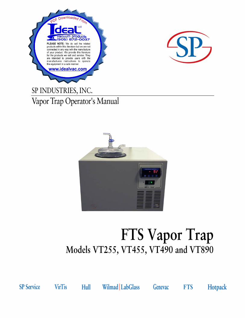
SP INDUSTRIES, INC. Vapor Trap Operator's Manual FTS Vapor Trap Models VT255, VT455, VT490 and VT890
Transcript of SP INDUSTRIES, INC. Vapor Trap Operator's Manual · SP INDUSTRIES, INC. Vapor Trap Operator's...
SP INDUSTRIES, INC. Vapor Trap Operator's Manual
FTS Vapor Trap Models VT255, VT455, VT490 and VT890

Rev 005, 02/10 i
Committed to Product Excellence …and Continuous Support
Copyright © 2010 SP Industries, Inc. All marks herein are used under license.
All brand or product names mentioned may be trademarks or registered trademarks of their respective companies.
Part Number MNL-048-A
Rev 005, 02/10
SP Industries Inc. Corporate Headquarters
935 Mearns Road 815 State Route 208 3538 Main Street
Warminster, PA 18974 USA Gardiner, NY 12525 USA Stone Ridge, NY 12484 USA
(800) 523-2327 (800) 431-8232 (800) 824-0400
(215) 672-7800 (800) 944-8559 (845) 687-0071
(845) 255-5000
SP Service (877) 548-4666
SP Service Fax (215) 672-1702
Website www.spindustries.com
This Vapor Trap Operator's Manual contains confidential and proprietary information of SP Industries, Inc. and may be used only by a recipient designated by and for purposes specified by SP Industries, Inc.
Reproduction of, dissemination of, modifications to, or the creation of derivative works from this Vapor Trap Operator's Manual, by any means and in any form or manner, is expressly prohibited, except with the prior written permission of SP Industries, Inc. Permitted copies of this document must retain all proprietary notices contained in the original.
The information in this document is subject to change without prior notice. Always confirm with SP Industries, Inc. that you are using the most current version of this document. SP Industries, Inc. is free to modify any of its products and services, in any manner and at any time, notwithstanding the information contained in this document.
THE CONTENTS OF THIS DOCUMENT SHALL NOT CONSTITUTE ANY WARRANTY OF ANY KIND, EITHER EXPRESSED OR IMPLIED, INCLUDING BUT NOT LIMITED TO THE IMPLIED WARRANTIES OF MERCHANTABILITY AND/OR FITNESS FOR A PARTICULAR PURPOSE OR GIVE RISE TO ANY LIABILITY OF SP INDUSTRIES, INC., ITS AFFILIATES OR ITS SUPPLIERS.
The terms and conditions governing the use of this Vapor Trap Operator's Manual shall consist of those set forth in written agreements with SP Industries, Inc.
© SP Industries, Inc. 2010
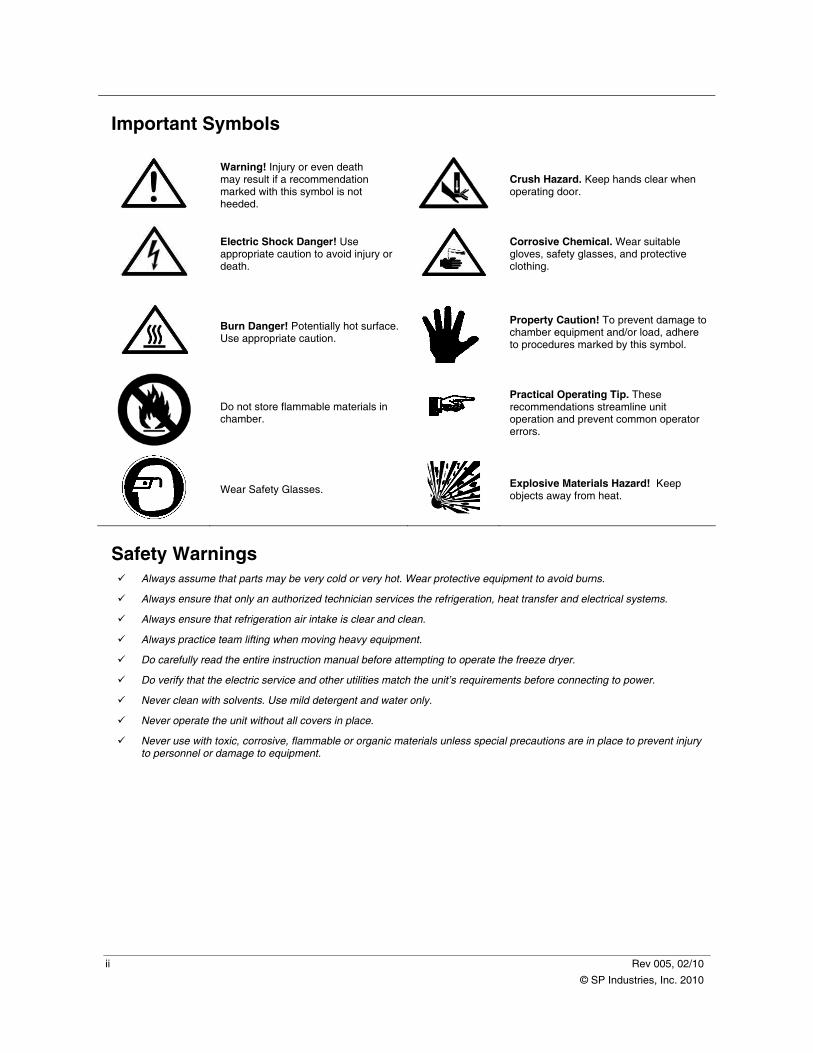
Important Symbols
Warning! Injury or even death may result if a recommendation marked with this symbol is not heeded.
Crush Hazard. Keep hands clear when operating door.
Electric Shock Danger! Use appropriate caution to avoid injury or death.
Corrosive Chemical. Wear suitable gloves, safety glasses, and protective clothing.
Burn Danger! Potentially hot surface. Use appropriate caution.
Property Caution! To prevent damage to chamber equipment and/or load, adhere to procedures marked by this symbol.
Do not store flammable materials in chamber.
Practical Operating Tip. These recommendations streamline unit operation and prevent common operator errors.
Wear Safety Glasses.
Explosive Materials Hazard! Keep objects away from heat.
Safety Warnings Always assume that parts may be very cold or very hot. Wear protective equipment to avoid burns.
Always ensure that only an authorized technician services the refrigeration, heat transfer and electrical systems.
Always ensure that refrigeration air intake is clear and clean.
Always practice team lifting when moving heavy equipment.
Do carefully read the entire instruction manual before attempting to operate the freeze dryer.
Do verify that the electric service and other utilities match the unit’s requirements before connecting to power.
Never clean with solvents. Use mild detergent and water only.
Never operate the unit without all covers in place.
Never use with toxic, corrosive, flammable or organic materials unless special precautions are in place to prevent injury to personnel or damage to equipment.
ii Rev 005, 02/10
© SP Industries, Inc. 2010
Rev 005, 02/10 iii
© SP Industries, Inc. 2010
Warranty Information FTS Vapor Trap is warranted by SP Industries to be free of defects in material and workmanship when operated under normal conditions as specified in the instructions provided in this manual. Please take this opportunity to locate the serial tag on your new FTS Vapor Trap and record the information below for future reference. SP Industries also recommends that you complete and return your unit’s warranty registration card.
Model Number
Serial Number
Part Number
Limited Warranty This warranty covers parts and labor for a period of one year, commencing the date of invoice, for any repairs deemed resultant of a defect in materials and/or workmanship by SP Industries, F.O.B. Stone Ridge.
Any factory approved changes or extensions to this warranty should be received in writing from SP Industries and filed with this warranty. If your system is eligible for coverage, please review this warranty thoroughly and contact the SP Service with any questions you may have. If your system is not covered by our warranty, or you are seeking optional or additional coverage, see sections below for service plans offered.
Covered
Parts and labor for a period of one (1) year from date of delivery. Any part found defective will be either repaired or replaced at SP Industries discretion, free of charges by SP Industries, at Stone Ridge, N.Y.
On site labor if repairs require that SP Industries personnel travel to the equipment.
Necessary parts and reasonable labor charges, if SP Industries agrees that local service is preferable. These parts and labor charges are subject to written approval prior to initiating the repair.
Travel time, mileage, travel and transportation expenses expended by SP Industries personnel if repairs require on-site labor.
Transportation of the equipment for repair.
Not Covered
SP Industries is not responsible for incidental or consequential damages, or damage resulting from negligence.
This writing is a final and complete integration of the agreement between the customer and SP Industries. SP Industries makes no other warranties express or implied, of merchantability, fitness or otherwise, with respect to the goods sold under this agreement, which extend beyond the description of this limited warranty.
SP Industries will have the right to inspect the equipment and determine the repairs or replacements necessary. The customer will be notified within a reasonable time of any damages incurred that are not covered by this warranty prior to initiation of any such repairs.
Any customer modification of this equipment, or any repairs undertaken without the prior written consent of SP Industries will render this limited warranty void.
Service Options Extended Warranty
This plan is an extension to the original new purchase warranty. You may extend the original warranty for one or two years total coverage. This plan does not provide Preventative Maintenance, nor does it cover travel or any freight expenses incurred.
Preventative Maintenance
This plan provides our customers with one or two onsite visits per year. We would perform a thorough preventative maintenance on your FTS equipment. You will be provided with a PM checklist and a certificate of calibration, which is traceable to N.I.S.T. The purchase of this plan also provides discounted parts and labor rate for additional service if deemed necessary at the time of the PM.
Service Contract
Service contracts (SC) are available post-expiration of any warrant period (standard or extended). SCs provide companies a plan which includes travel, labor, and priority response time. Any necessary parts are provided at a discounted rate. Two levels (silver and gold) are available for varying customer needs.
Contact SP Service at (877) 548-4666 for details.

iv Rev 005, 02/10
© SP Industries, Inc. 2010

Rev 005, 02/10 v
© SP Industries, Inc. 2010
Contents
Important Symbols ............................................................................................................................................... ii Safety Warnings................................................................................................................................................... ii Warranty Information .......................................................................................................................................... iii
Introduction............................................................................................................................................ 1 Key Features ...................................................................................................................................................1 Key Features ...................................................................................................................................................2
Installation and Startup......................................................................................................................... 3 Initial Inspection ...................................................................................................................................................3 Installation............................................................................................................................................................3
Ambient Air Requirements...............................................................................................................................3 Services and Utilities .......................................................................................................................................4
Vapor Trap Setup.................................................................................................................................................5 Initial Setup......................................................................................................................................................5
Basic Operation ..................................................................................................................................... 7 Getting Started.....................................................................................................................................................7
Power On ........................................................................................................................................................7 Shut Down.......................................................................................................................................................7 Defrost.............................................................................................................................................................8
General Maintenance .......................................................................................................................... 11 Cleaning.............................................................................................................................................................11
Appendix A: Calibration...................................................................................................................... 13 Front Panel Buttons ...........................................................................................................................................13 Unlocking the Display ........................................................................................................................................14 Setting Numeric Values .....................................................................................................................................14 Calibration Procedure ........................................................................................................................................15 Locking the Display............................................................................................................................................17
Appendix B: Troubleshooting............................................................................................................ 19

Chapter
1
Rev 005, 02/10 1
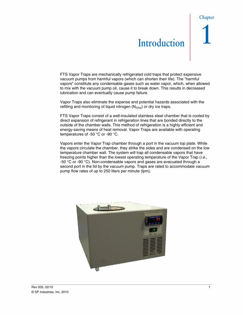
Introduction FTS Vapor Traps are mechanically refrigerated cold traps that protect expensive vacuum pumps from harmful vapors (which can shorten their life). The “harmful vapors” constitute any condensable gases such as water vapor, which, when allowed to mix with the vacuum pump oil, cause it to break down. This results in decreased lubrication and can eventually cause pump failure. Vapor Traps also eliminate the expense and potential hazards associated with the refilling and monitoring of liquid nitrogen (N2(liq)) or dry ice traps. FTS Vapor Traps consist of a well-insulated stainless steel chamber that is cooled by direct expansion of refrigerant in refrigeration lines that are bonded directly to the outside of the chamber walls. This method of refrigeration is a highly efficient and energy-saving means of heat removal. Vapor Traps are available with operating temperatures of -50 °C or -90 °C. Vapors enter the Vapor Trap chamber through a port in the vacuum top plate. While the vapors circulate the chamber, they strike the sides and are condensed on the low temperature chamber wall. The system will trap all condensable vapors that have freezing points higher than the lowest operating temperature of the Vapor Trap (i.e., -50 °C or -90 °C). Non-condensable vapors and gases are evacuated through a second port in the lid by the vacuum pump. Traps are rated to accommodate vacuum pump flow rates of up to 250 liters per minute (lpm).
© SP Industries, Inc. 2010
Introduction FTS Vapor Trap
2 Rev 005, 02/10
© SP Industries, Inc. 2010
Key Features
• Small footprint.
• Mechanical refrigeration (air-cooled).
• Digital temperature display.
• Efficient removal of heat.
• -50 °C or -90 °C trapping temperatures.
• Available in 2-, 4-, or 8-liter capacities.
Note: SP Industries builds each unit according to the options purchased. Review the standard sections, as well as the relevant optional sections of this manual.
Chapter
2
Rev 005, 02/10 3
© SP Industries, Inc. 2010
Installation and Startup
Initial Inspection Upon receiving your Vapor Trap, inspect all contents of your shipment for damage. Check packing material for small accessory items. Remove all packing material carefully and inspect for concealed shipping damage. Inspect the inside of machine for any visible damage. In the unlikely event that shipping damage has occurred, retain all packing material and contact your freight carrier immediately.
Note: In the event of shipping damage, SP Industries will cooperate in the matter of collecting your claim; however, SP Industries is not responsible for the collection or free replacement of material. When possible, replacement parts will be shipped and invoiced to you, making them a part of your claim.
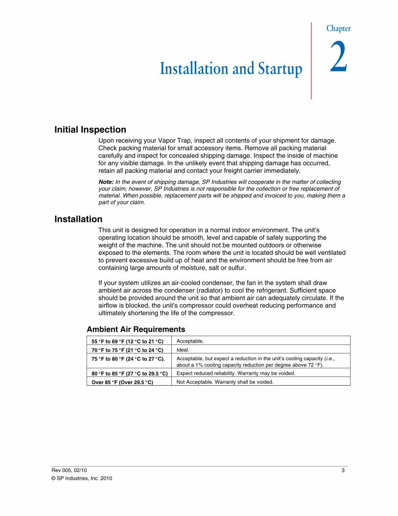
Installation This unit is designed for operation in a normal indoor environment. The unit’s operating location should be smooth, level and capable of safely supporting the weight of the machine. The unit should not be mounted outdoors or otherwise exposed to the elements. The room where the unit is located should be well ventilated to prevent excessive build up of heat and the environment should be free from air containing large amounts of moisture, salt or sulfur. If your system utilizes an air-cooled condenser, the fan in the system shall draw ambient air across the condenser (radiator) to cool the refrigerant. Sufficient space should be provided around the unit so that ambient air can adequately circulate. If the airflow is blocked, the unit’s compressor could overheat reducing performance and ultimately shortening the life of the compressor.
Ambient Air Requirements 55 °F to 69 °F (12 °C to 21 °C) Acceptable.
70 °F to 75 °F (21 °C to 24 °C) Ideal.
75 °F to 80 °F (24 °C to 27 °C). Acceptable, but expect a reduction in the unit’s cooling capacity (i.e., about a 1% cooling capacity reduction per degree above 72 °F).
80 °F to 85 °F (27 °C to 29.5 °C) Expect reduced reliability. Warranty may be voided.
Over 85 °F (Over 29.5 °C) Not Acceptable. Warranty shall be voided.
Installation and Startup FTS Vapor Trap
Services and Utilities
Electrical Requirements The voltage, phase and frequency requirements are specified on the serial tag, located on the rear panel of the unit. The following voltage and frequency tolerances shall be considered acceptable: -5%, +10% VAC and ±3 Hz.
ELECTRIC SHOCK DANGER! ONLY QUALIFIED PERSONNEL SHOULD CONNECT THE UNIT TO THE REQUIRED ELECTRICAL SUPPLY.
When connecting the unit to its intended electrical supply:
1. Verify that the facility’s electrical supply matches the electrical requirements for the machine. Refer to the unit’s serial tag.
2. The electric supply wiring must be capable of maintain maintaining sufficient voltage to the outlet receptacle during peak loads.
Note: To ensure an adequate electrical supply for your equipment, measure the voltage at the outlet receptacle while that receptacle is under load.
3. Ensure that the electrical supply includes a properly sized circuit breaker and that it is installed near the equipment. Refer to the unit’s serial tag.
4. Ensure that the power switch on the front panel of the machine is in the Off position (0).
5. Plug the unit’s line cord into the outlet receptacle.
Note: Avoid the use of long extension cords as these can cause significant power drops between the outlet receptacle and the unit.
6. Toggle the unit’s power switch to the On position (1). The unit should power up.
7. If the unit vibrates excessively upon start up, recheck the facility’s voltage that it is within the acceptable range.
PRACTICAL OPERATING PROCEDURE! WHEN FOLLOWING LOCKOUT-TAGOUT (LOTO) PROCEDURES, PLUG THE APPROPRIATE DEVICE INTO THE LINE CORD AND/OR FOLLOW YOUR FACILITY’S LOTO PROCEDURES.
4 Rev 005, 02/10
© SP Industries, Inc. 2010
FTS Vapor Trap Installation and Startup
Vapor Trap Setup
PRACTICAL OPERATING TIP. THE VAPOR TRAP IS INTENDED TO BE CONNECTED BETWEEN YOUR PROCESS AND THE VACUUM PUMP.
Initial Setup If your unit is equipped with a stainless or glass chamber lid:
1. Apply high-vacuum grease to the black gasket in the top of the Vapor Trap and position the lid so that the long tube in the center runs down into the chamber.
2. Connect the vacuum line that runs from the vacuum pump to the off-center port using the appropriate connectors.
3. Connect the vacuum line that runs to your process/application to the center port using the appropriate connectors.
If your unit is equipped with a glass insert vessel:
1. Insert the pre-formed tube of copper mesh into the chamber. Press it against the sidewall with the lower edge touching the bottom of the chamber.
2. Press the precut circular piece of copper gauze into the bottom of the chamber.
3. Slowly push the glass liner into the center of the chamber until it fits securely in place. DO NOT FORCE IT! If the liner does not fit easily, remove it and check for folds or bunching in the copper gauze. Retry fitting the liner in place.
BURN DANGER. Methanol and Ethanol are flammable and their use may be restricted by your facility’s safety regulations. SP Industries recommends consulting with the appropriate personnel before using a specific fluid.
4. Pour the selected heat transfer fluid into the space between the glass insert and the chamber wall until the level of the fluid reaches the top of the copper gauze. This shall improve the heat transfer between the insert and the chamber wall, and prevent frost from forming in this space.
Note: Frost will act as an insulator and reduce heat transfer capabilities.
5. The O-ring on the glass liner cover should have a light coating of high-vacuum grease on it before pushing it onto the liner neck.
6. Connect the vacuum line that runs to your process/application to the center port on the glass insert lid using the appropriate connectors.
7. Connect the vacuum line that runs from the vacuum pump to the off-center port on the glass insert lid using the appropriate connectors.
PRACTICAL OPERATING TIP. IF YOU ARE TRAPPING HAZARDOUS CHEMICALS, SP INDUSTRIES RECOMMENDS INSTALLING A CHEMICAL FILTER TRAP INLINE BETWEEN THE VAPOR TRAP AND THE VACUUM PUMP.
Rev 005, 02/10 5
© SP Industries, Inc. 2010

Installation and Startup FTS Vapor Trap
6 Rev 005, 02/10
© SP Industries, Inc. 2010
Chapter
3
Rev 005, 02/10 7
Basic Operation
Getting Started Prior to operating your Vapor Trap, check all vacuum connections and verify that they are secure. Keep in mind that the Vapor Trap run continuously until it has accumulated a full load of ice. Once the Vapor Trap chamber becomes loaded with ice, shut down the unit and defrost the chamber. If you operate your Vapor Trap with the glass insert vessel, you may want to consider a second vessel, as well. Having the ability to alternate between a fully loaded vessel and one that is clean and empty will allow for a more continuous process. When trapping vapors that are known to cause corrosion, particularly to stainless steel, consider using a glass liner.
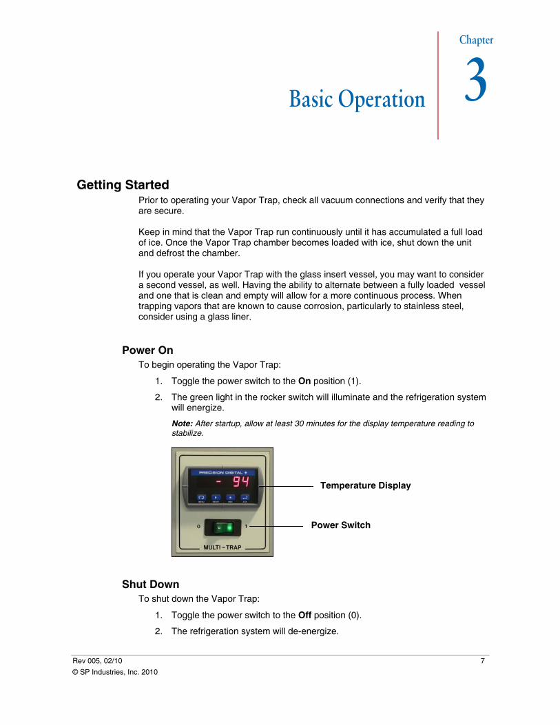
Power On To begin operating the Vapor Trap:
1. Toggle the power switch to the On position (1).
2. The green light in the rocker switch will illuminate and the refrigeration system will energize.
Note: After startup, allow at least 30 minutes for the display temperature reading to stabilize.
Temperature Display
Power Switch
Shut Down To shut down the Vapor Trap:
1. Toggle the power switch to the Off position (0).
2. The refrigeration system will de-energize.
© SP Industries, Inc. 2010
Basic Operation FTS Vapor Trap
Defrost When the Vapor Trap’s chamber becomes loaded with ice, it shall be necessary to defrost the system.
WEAR EYE AND RESPIRATORY PROTECTION. DEPENDING ON THE COMPOSITION OF THE VAPOR THAT HAS BEEN TRAPPED, IT MAY BE NECESSARY TO WEAR SAFETY GLASSES AND RESPIRATORY WHILE DEFROSTING THE UNIT.
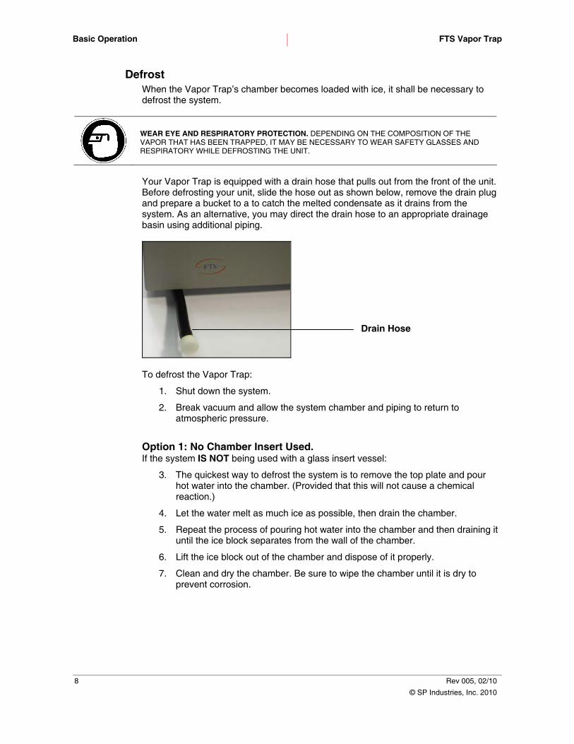
Your Vapor Trap is equipped with a drain hose that pulls out from the front of the unit. Before defrosting your unit, slide the hose out as shown below, remove the drain plug and prepare a bucket to a to catch the melted condensate as it drains from the system. As an alternative, you may direct the drain hose to an appropriate drainage basin using additional piping.
Drain Hose
To defrost the Vapor Trap:
1. Shut down the system.
2. Break vacuum and allow the system chamber and piping to return to atmospheric pressure.
Option 1: No Chamber Insert Used. If the system IS NOT being used with a glass insert vessel:
3. The quickest way to defrost the system is to remove the top plate and pour hot water into the chamber. (Provided that this will not cause a chemical reaction.)
4. Let the water melt as much ice as possible, then drain the chamber.
5. Repeat the process of pouring hot water into the chamber and then draining it until the ice block separates from the wall of the chamber.
6. Lift the ice block out of the chamber and dispose of it properly.
7. Clean and dry the chamber. Be sure to wipe the chamber until it is dry to prevent corrosion.
1. x
© SP Industries, Inc. 2010
2. x
8 Rev 005, 02/10
FTS Vapor Trap Basic Operation
Option 2: Glass Insert Vessel Used. If the system IS being used with a glass liner:
3. Use caution when removing and defrosting the glass insert vessel.
WARNING! FOLLOW THESE INSTRUCTIONS TO AVOID BREAKAGE. DO NOT ALLOW THE GLASS LINER TO DEFROST SLOWLY. RESTRICT HOT WATER TO THE OUTSIDE SURFACE OF THE GLASSWARE ONLY. POURING HOT WATER INTO THE GLASSWARE LINER TO MELT THE ICE WILL RESULT IN BREAKAGE.
4. Remove the fully loaded glass insert vessel and quickly submerge it in hot water up to, but not over and/or in the glassware.
Note: This method will cause the ice to melt quickly at the liner wall, leaving room for the ice block to expand as it defrosts.
5. Allow the ice to melt completely.
6. Clean and dry the inner surface of the liner.
Rev 005, 02/10 9
© SP Industries, Inc. 2010

Basic Operation FTS Vapor Trap
10 Rev 005, 02/10
© SP Industries, Inc. 2010
Chapter
4
Rev 005, 02/10 11
General Maintenance
Proper routine maintenance is the key to an efficiently operating unit with minimal downtime. The following section provides instructions on how to maintain your Vapor Trap.
WARNING! HAZARDOUS VOLTAGES. RISK OF ELECTRIC SHOCK. DISCONNECT ALL POWER BEFORE SERVICING THIS UNIT. REFER ALL SERVICE ISSUES TO QUALIFIED SERVICE PERSONNEL.
NOTICE! ONLY QUALIFIED PERSONNEL SHOULD PERFORM MAINTENANCE ON THE REFRIGERATION SYSTEM. ONLY EPA CERTIFIED TECHNICIANS MAY EVACUATE OR CHARGE REFRIGERANTS.
HAZARDOUS MATERIAL/CONTACT HAZARD! THE CHEMICALS USED IN THIS UNIT ARE CONTAINED WITHIN FULLY ENCLOSED SYSTEMS. NO MAINTENANCE ACTIVITIES INVOLVING THE REFRIGERATION SYSTEM ARE TO BE PERFORMED BY THE END-USER.
HOT SURFACE! POTENTIAL BURN HAZARD! THE COMPRESSOR AND ASSOCIATED TUBING IN THE LOWER PORTION OF THE UNIT ARE LIKELY TO BE HOT.
Cleaning
CAUTION! PROPER SAFETY EQUIPMENT SUCH AS EYE AND FACE PROTECTION, GLOVES AND A DUST MASK SHOULD BE USED WHEN CLEANING AND/OR SERVICING EQUIPMENT.
To properly clean the Vapor Trap
1. Check power switch for proper operation.
2. Remove power by disconnecting the unit from its electrical supply.
3. Wipe down all exterior cabinet surfaces with a damp cleaning cloth.
4. Use a vacuum to remove dust and debris from the refrigeration system condenser, screens and other openings.
5. Remove cabinet panels.
6. Blow compressed air thoroughly from the top of the unit to bottom. Allow several minutes for dust and debris to settle and repeat.
7. Check for areas that have frosted during operation and insulate as needed.
8. Replace cabinet panels.
9. Reconnect the electrical power supply.
© SP Industries, Inc. 2010

General Maintenance FTS Vapor Trap
12 Rev 005, 02/10
© SP Industries, Inc. 2010
Appendix
A
Rev 005, 02/10 13
Appendix A: Calibration Your Vapor Trap includes a Precision Digital Sabre T Model PD743 Temperature Meter. The Temperature Meter, which functions primarily as a temperature display, is factory-calibrated by Precision Digital prior to being shipped to SP Industries. Calibration equipment is certified to National Institute of Standards and Technology (NIST) traceable standards, according to the manufacturer. Once the display is installed in your Vapor Trap, SP Industries performs recalibration and verification of the Temperature Meter using a thermocouple simulator traceable to NIST standards. SP Industries and Precision Digital recommend the recalibration and verification of your Vapor Trap’s Sabre T Model PD743 Temperature Meter at least once every twelve months. Always recalibrate using NIST traceable instruments that are within one year of the last calibration.
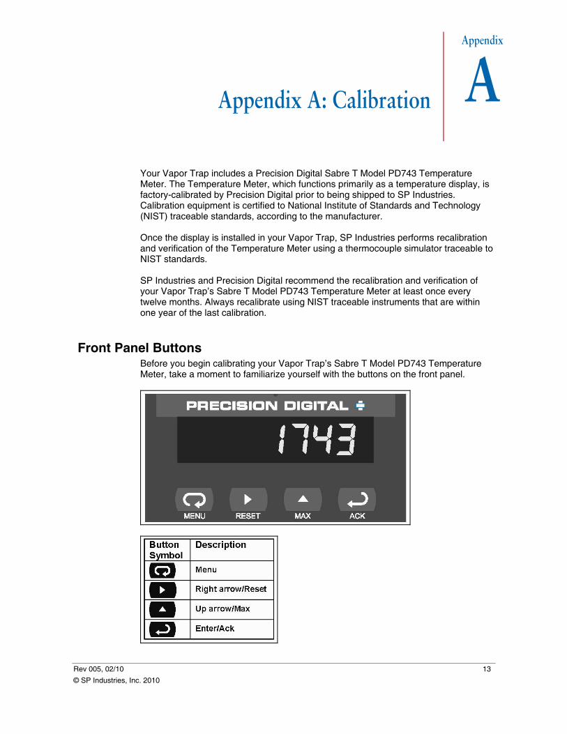
Front Panel Buttons Before you begin calibrating your Vapor Trap’s Sabre T Model PD743 Temperature Meter, take a moment to familiarize yourself with the buttons on the front panel.
© SP Industries, Inc. 2010
Appendix A: Calibration FTS Vapor Trap
Unlocking the Display Your Vapor Trap’s Sabre T Model PD743 Temperature Meter has been locked using a unit-specific password to prevent unintentional changes to factory settings. Before you can calibrate your Temperature Meter, you will need to unlock the display using the correct password.
Note: Your Temperature Meter password is the last four digits of your Vapor Trap’s serial number. Refer to the serial tag, located on the back panel of your unit.
PROPERTY CAUTION! TO PREVENT DAMAGE TO THE TEMPERATURE METER FOLLOW ALL INSTRUCTIONS IN THIS SECTION, INCLUDING PASSWORD LOCKING AND UNLOCKING, AND CALIBRATION PROCEDURES. USE CARE NOT TO ALTER ANY TEMPERATURE METER SETTINGS NOT DISCUSSED IN THIS MANUAL.
To unlock the display:
1. Turn on the Vapor Trap.
2. Press the Menu button.
3. Use the Up arrow to select the PASS (Password) menu. Press the Enter/Ack (Enter/Acknowledge) button.
4. If the Temperature Meter has been locked using a password, it will display LoCd (Locked). Press the Enter/Ack button to enter your password (see Setting Numerical Values). Your Temperature Meter password is the last four digits of your Vapor Trap’s serial number.
Note: If the Temperature Meter displays unLC, it has already been unlocked. Proceed to the Calibration procedure of this section.
5. Press the Enter/Ack button. The Temperature Meter will display unLC.
Setting Numeric Values Use the Right and Up arrow buttons to set numeric values when entering your password or calibrating temperature points.
Note: The Temperature Meter display must be unlocked before you can set and enter numeric values.
To set numeric values:
1. Press the Up arrow to increase the value of the digit you wish to set.
2. Press the Right arrow to select the next digit you wish to set.
3. Press the Enter/Ack button to enter the numeric value or press the Menu button to exit without changes.
14 Rev 005, 02/10
© SP Industries, Inc. 2010
FTS Vapor Trap Appendix A: Calibration
Calibration Procedure To calibrate the Vapor Trap’s Sabre T Model PD743 Temperature Meter, SP Industries recommends using a thermocouple simulator capable of accepting a Type T thermocouple and traceable to NIST standards. To calibrate the Temperature Meter:
1. Turn on the Vapor Trap. Allow the Vapor Trap to run for at least 30 minutes before calibrating to ensure accuracy.
2. Unlock the Temperature Meter.
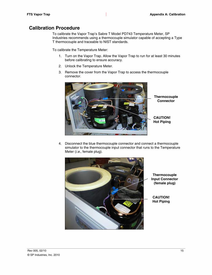
3. Remove the cover from the Vapor Trap to access the thermocouple connector.
Thermocouple Connector
CAUTION! Hot Piping
4. Disconnect the blue thermocouple connector and connect a thermocouple simulator to the thermocouple input connector that runs to the Temperature Meter (i.e., female plug).
Thermocouple Input Connector
(female plug)
CAUTION! Hot Piping
Rev 005, 02/10 15
© SP Industries, Inc. 2010
Appendix A: Calibration FTS Vapor Trap
5. When recalibrating the Temperature Meter, the manufacturer recommends using the Fahrenheit scale, as this provides a greater degree of accuracy to the calibration. If you prefer to measure temperature in degrees Celsius, the scale may be changed after calibration is completed. To change the temperature scale to degrees Fahrenheit:
a. Press the Menu button.
b. Select the SETu (Setup) menu. Press the Enter/Ack (Enter/Acknowledge) button.
c. Use the Up arrow to select the F C (°F or °C) menu. Press the Enter/Ack button.
d. Use the Up arrow to select °F. Press the Enter/Ack button.
e. Press Menu button to exit and return to Run mode.
6. The Temperature Meter is designed to be calibrated at two temperature points (i.e., Input 1 and Input 2). When using a thermocouple simulator to recalibrate the Temperature Meter, SP Industries recommends applying a low temperature signal of -130 °F (-90 °C) and a high temperature of 68 °F (20 °C). Calibrate the Temperature Meter’s low and high temperature points (Input 1 and Input 2) as follows:
a. Press the Menu button.
b. Use the Up arrow to select the ProG (Program) menu. Press the Enter/Ack button.
c. Select the CAL (Calibrate) menu. Press the Enter/Ack button.
d. The Temperature Meter will display inP1 (Input 1).
e. Using a thermocouple simulator, apply a -130 °F signal to Input 1. Press the Enter/Ack button and wait for the display to start flashing inP1. When the display stops flashing, DiS1 will appear. Press the Enter/Ack button again and set the display value to -130 using the Reset and Max buttons
f. Press the Enter/Ack button.
g. The Temperature Meter will display inP2 (Input 2).
h. Using a thermocouple simulator, apply a 68 °F signal to Input 2. Press the Enter/Ack button and wait for the display to start flashing inP2. When the display stops flashing DiS2 will appear. Press the Enter/Ack button again and set the display value to 68 using the Reset and Max buttons.
7. Press the Enter/Ack button. After the Temperature Meter accepts the Input 2 temperature, the display will flash CJr. Wait until the display stops flashing. This completes the recalibration procedure. Remove the thermocouple simulator and reconnect the Vapor Trap’s thermocouple connectors.
8. If desired, set the digital display to measure temperature in degrees Celsius.
9. Lock the digital display again to prevent unauthorized changes to the factory settings.
16 Rev 005, 02/10
© SP Industries, Inc. 2010
FTS Vapor Trap Appendix A: Calibration
Rev 005, 02/10 17
© SP Industries, Inc. 2010
Locking the Display To lock the display:
1. Press the Menu button.
2. Use the Up arrow to select the PASS (Password) menu. Press the Enter/Ack (Enter/Acknowledge) button.
3. If the Temperature Meter is unlocked, it will display unLC (Unlocked).
4. Press the Enter/Ack button.
5. Enter the last four digits of your Vapor Trap’s serial number, or create a new password.
6. Press the Enter/Ack button to enter your password.
7. The Temperature Meter will display LoCd (Locked).

Appendix A: Calibration FTS Vapor Trap
18 Rev 005, 02/10
© SP Industries, Inc. 2010
Appendix
B
Rev 005, 02/10 19
© SP Industries, Inc. 2010
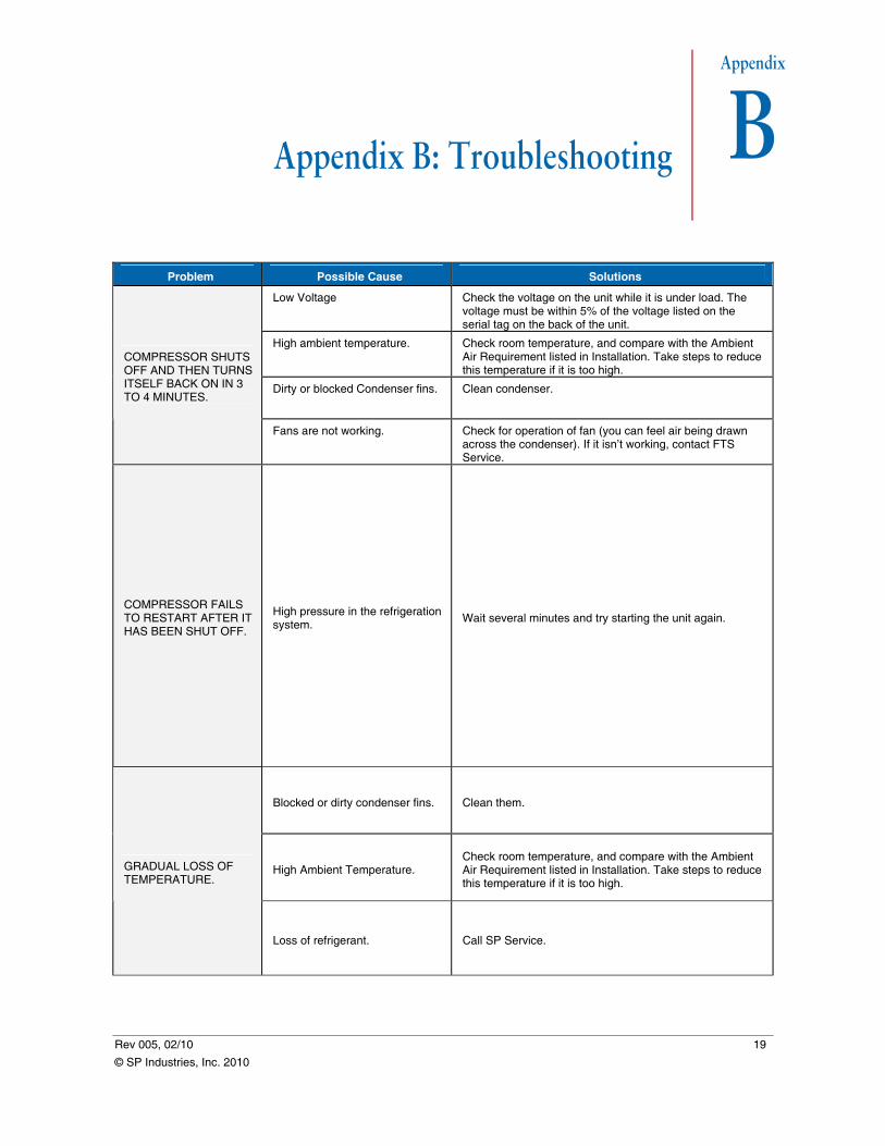
Appendix B: Troubleshooting
Problem Possible Cause Solutions
Low Voltage Check the voltage on the unit while it is under load. The voltage must be within 5% of the voltage listed on the serial tag on the back of the unit.
High ambient temperature. Check room temperature, and compare with the Ambient Air Requirement listed in Installation. Take steps to reduce this temperature if it is too high.
Dirty or blocked Condenser fins. Clean condenser.
COMPRESSOR SHUTS OFF AND THEN TURNS ITSELF BACK ON IN 3 TO 4 MINUTES.
Fans are not working. Check for operation of fan (you can feel air being drawn across the condenser). If it isn’t working, contact FTS Service.
COMPRESSOR FAILS TO RESTART AFTER IT HAS BEEN SHUT OFF.
High pressure in the refrigeration system.
Wait several minutes and try starting the unit again.
Blocked or dirty condenser fins. Clean them.
High Ambient Temperature. Check room temperature, and compare with the Ambient Air Requirement listed in Installation. Take steps to reduce this temperature if it is too high.
GRADUAL LOSS OF TEMPERATURE.
Loss of refrigerant. Call SP Service.

Appendix B: Troubleshooting FTS Vapor Trap
20 Rev 005, 02/10
© SP Industries, Inc. 2010


SP Industries 3538 Main Street
Stone Ridge, NY 12484 USA www.SPIndustries.com
(800) 824-0400 (845) 687-0071