SP-2100 Operation Laboratory Manual pH/mV/Temp....
23
SP-2100 Laboratory pH/mV/Temp. Meter Operation Manual
Transcript of SP-2100 Operation Laboratory Manual pH/mV/Temp....

SP-2100 Laboratory
pH/mV/Temp. Meter
Operation Manual
Content
1. Specifications …..1
2 .Panel Description …..2 2.1 Front panel 2 2.2 Sockets 2 2.3 Display 3 2.4 Keypad 4
3 .Operation …..5 3.1 Block diagram of operation 5 3.2 pH measurement 5
3.2.1 pH measurement mode 5 3.2.2 pH Auto-Read drift control 5
3.3 ORP Measurement 7 3.3.1 ORP measurement mode 7 3.3.2 ORP Auto-Read drift control 7
4 .Temperature Compensation…..8
5 .Calibration…..9 5.1 pH Calibration 9
5.1.1 Preset TECH. buffer auto calibration 9 5.1.2 Manual calibration 11
5.2 ORP zero-point calibration 12
6 .Data Transmission via RS-232…..13 6.1 Introduction 13 6.2 MODBUS rule 13 6.3 Data frame format 13 6.4 SP2100 communication protocol 14 6.5 Connection of communication 17 6.6 MODBUS name and address table 17
7 .Error Messages…..20
8 .Maintenance…..21

1. Specifications
Model SP-2100 Measuring item pH / ORP / Temperature
pH -2.00~16.00pH
ORP -1999~1999mV Measuring Range
TEMP -10.0~110.0°C
pH 0.01pH ORP 1mV Resolution
TEMP 0.1°C
pH ±0.01pH±1Digit ORP ±0.05%±1Digit Accuracy
TEMP ±0.2°C ±1Digit
Auto-Read Yes
Build in Tech. buffers automatic recognition, up to 3-point auto calibration, showing offset and slope after calibrationCalibration
Manual knob-adjustment
PT-1000 or NTC 30K probe with auto recognition and temperature correction function
Temperature Compensation
Manual adjustment
Ambient Temperature 0~50°C
Storage Temperature -20~70°C
Impedance Input ≧1012Ω
Display Large 0.8” LCD display with backlight function
RS232 Interface RS-232 (Print / MODBUS-RTU)
Power Supply 4 AA batteries or 6V AC/DC adaptor
Power Consumption 1W max.
Dimensions 220×190×70mm (L×W×H)
Weight 0.8Kg
1

2. Panel Description
2.1 Front panel:
2.2 Sockets:
POWER :DC 6V Adaptor socket RS-232 :RS-232 interface for computer connection T/P :Temperature probe socket REF. :Reference probe socket pH/ISE :BNC socket for pH, metal, or specific ion electrode
2
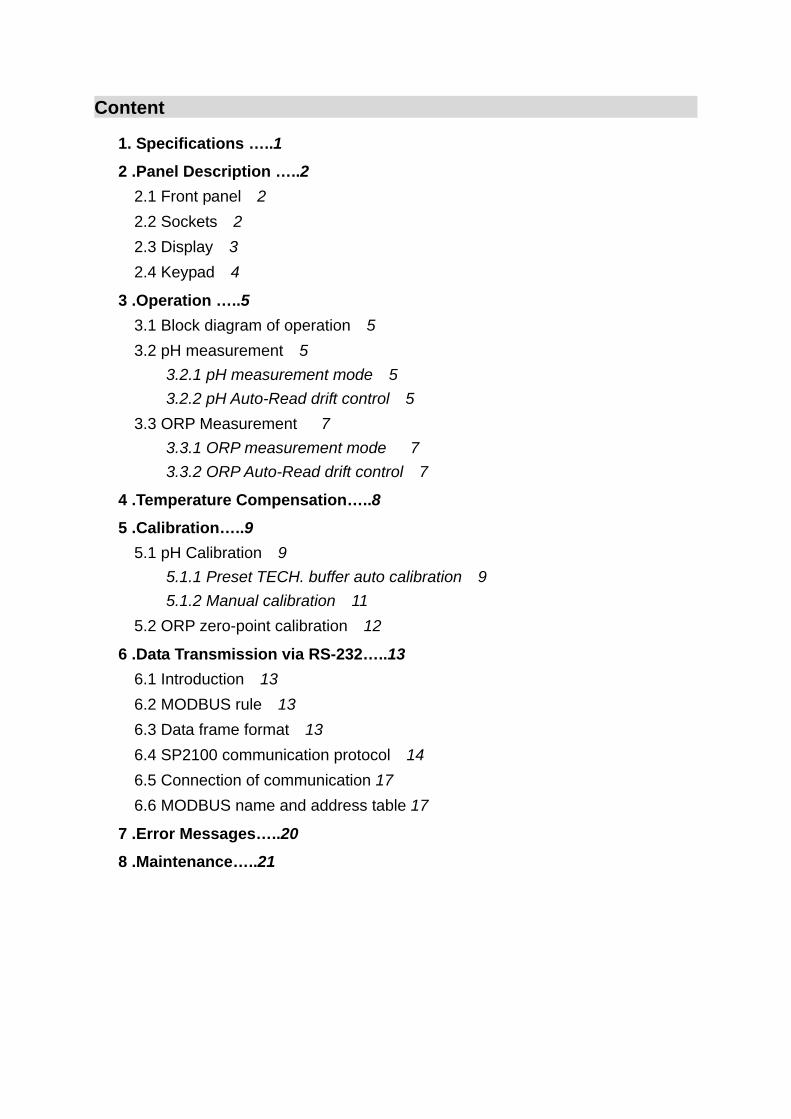
2.3 Display:
Measuring Mode
Unit Display
Auto Temp
Compensation
Calibration Mode
Low Battery Warning
Auto Read Drift Control
Auto Mode
Signal output
& Hold
Manual Temp
Compensation
3
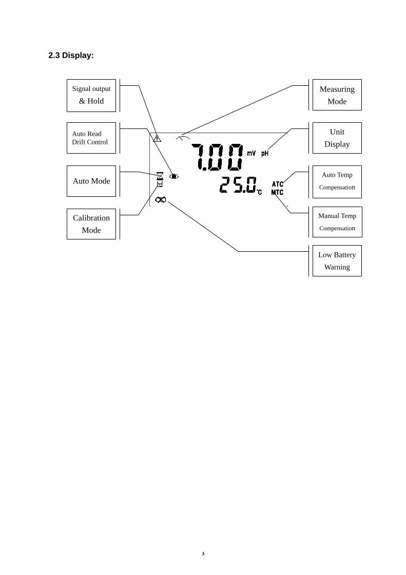
2.4 Keypad:
Power ON/OFF
Switch from pH or ORP or Temperature Correctiion mode.
Enter calibration mode / Select buffer type
Zero point calibration adjustment knob with press-down safety function. (Please press down before tuning)
Slope calibration adjustment knob with press-down safety function. . (Please press down before tuning)
Temperature adjustment knob with press-down safety function. . (Please press down before tuning)
MODE
ENT
CALIB
SLOPE
TEMP
4

3. Operation
3.1 Block diagram of operation Power on
Show the software version
Press
pH measurement mode
(CT) Temperature Calibration Mode
Enter into Auto-Read function
Enter into Auto-Read function
Process Auto-Read& Hold
Exit Auto-Read & backto measurement mode
Process Auto-Read & Hold
Exit Auto-Read & back to measurement mode
MODE
ENT
MODE
MODE
ENT
MODE
ORP measurement mode
ENT
Press
Press
Press
Press
ENT
MODE
ENT
Press
Press
Press
Press Press
Enter into Temp. Calibration Mode
5

3.2 pH measurement 3.2.1 pH measurement mode
Press to power on, and press to enter pH measurement mode which is in a continuously measuring status.
3.2.2 pH Auto-Read Drift Control Under pH measurement mode, press to activate on Auto-Read function.
Press to start next Auto-Read measurement.
Press to exit Auto-Read function and back to pH measurement mode.
Press
Press
ENT
MODE
MODE
ENT
ENT
ENT
The signs come out, and the measurement reading is hold.
The signs twinkle, and the instrument start to run the Auto-Read function until the reading is stable.
After the reading is stable, the signs stop twinkling, and the measurement is hold.
6

3.3 ORP Measurement 3.3.1 ORP measurement mode
Press to power on, and press to enter ORP measurement mode which is in a continuously measuring status.
3.3.2 ORP Auto-Read Drift Control Under ORP measurement mode, press to activate Auto-Read function.
。
Press to exit Auto-Read function and back to ORP measurement mode.
MODE
ENT
MODE
Press to start next Auto-Read measurement.
Press
Press
ENT
ENT
ENT
The signs come out, and the measurement reading is hold.
The signs twinkle, and the instrument start to run the Auto-Read function until the reading is stable.
After the reading is stable, the signs stop twinkling, and the measurement is hold.
7

4. Temperature compensation
Under pH measurement mode, the temperature of sample solution infects the reading of measurement, thus, a temperature compensation to the measurement has to be made in order to correct the pH reading error.
1. Manual Compensation: If you do not use a temperature probe, you may press and tune up the “TEMP. knob” until the figure is accorded with the temperature of sample solution before starting a measurement.
2. Automatic Compensation: The instrument can automatically recognize whether the temperature probe is a PT1000 or a NTC30K system. Plug in the temperature probe, the instrument can measure the temperature of the sample solution temperature and compensate the main measurement reading automatically. In addition, you may press and tune up the “TEMP. knob” to correct the temperature reading
TEMP
TEMP
8
5. Calibration
5.1 pH calibration 1. The instrument provide two types of calibration including TECH buffer solution
automatic calibration and manual calibration
The preset TECH buffer-solutions’ standard values are: pH4.01、pH7.00、pH10.00.
2. The TECH buffer-solution automatic calibration can be done with single-point,
dual-point, or three-point calibration.
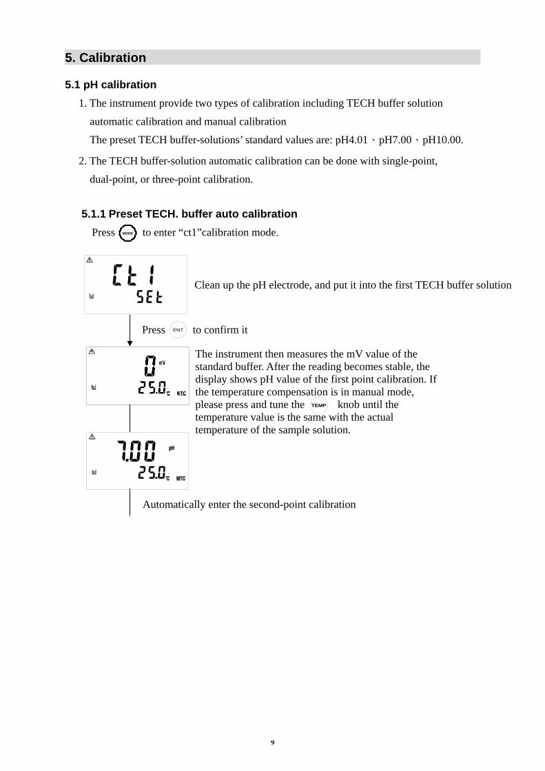
5.1.1 Preset TECH. buffer auto calibration
Press to enter “ct1”calibration mode.
The instrument then measures the mV value of the standard buffer. After the reading becomes stable, the display shows pH value of the first point calibration. If the temperature compensation is in manual mode, please press and tune the knob until the temperature value is the same with the actual temperature of the sample solution.
Press to confirm it
Automatically enter the second-point calibration
Clean up the pH electrode, and put it into the first TECH buffer solution
MODE
ENT
TEMP
9

Press to confirm it
Press to confirm it
The instrument then measures the mV value of the second standard buffer. After the reading becomes stable, the display shows pH value of the second point calibration. If the temperature compensation is in manual mode, please press and tune the knob until the temperature value is the same with the actual temperature of the sample solution.
Automatically enter the third-point calibration
Automatically back to measurement mode
Press to exit and finish it as a single-point calibration
Press to exit and finish it as a dual-point calibration
The instrument then measures the mV value of the third standard buffer. After the reading becomes stable, the display shows pH value of the third point calibration. If the temperature compensation is in manual mode, please press and tune the knob until the temperature value is the same with the actual temperature of the sample solution.
Clean up the pH electrode, and put it into the third TECH buffer solution
Clean up the pH electrode, and put it into the second TECH buffer solution
MODE
MODE
ENT
ENT
TEMP
TEMP
10

5.1.2 Manual calibration The pH manual calibration should be proceeded under the pH measurement mode.
0
Press & hold the “CALIB” knob until there is a sign on the display. Then, tune the knob to adjust to the “zero point” (pH 7.00).
Press & hold the “SLOPE” knob until there is a sign on the display. Then, tune the knob to adjust the “slope” (pH 4.01).
Clean up the pH electrode, and put it into pH 7.00 buffer solution. If the temperature compensation is in manual mode, please press and tune the knob until the temperature value is the same with the actual temperature of the sample solution.
Release the knob. Then, the sign is disappeared. It represents that the zero point calibration has been done.
Clean up the pH electrode, and put it into pH 4.01 buffer solution. If the temperature compensation is in manual mode, please press and tune the knob until the temperature value is the same with the actual temperature of the sample solution.
Release the knob. Then, the sign is disappeared. It represents that the slope calibration has been done.
TEMP
TEMP
11

5.2 ORP zero-point calibration The ORP measurement can be calibrated the mV drift or to adjust the corresponding mV value by applying ORP standard solution. Press to enter ORP measurement mode. Proceed the calibration as follows:
Press & hold the “CALIB” knob until there is a sign on the display. Then, tune the knob to correct the ORP drift until the display value is accordance with the value of the standard solution.
Clean up the ORP electrode, and put it into ORP standard solution.
Release the knob. Then, the sign is disappeared. It represents that the offset or corresponding mV calibration has been done.
MODE
12

6. Data Transmission via RS-232
6.1 Introduction
The SP-2100 applies standard MODBUS protocol, and supports RTU transmission mode. It supports even parity verification and allows PLC, RTU, SCADA system or the third parity monitor software which is compatible with MODBUS protocol to proceed practical information and data transmission.
Factory default (Unchangeable): The address of instrument is 1. The baud rate is 19200. The transmission code mode is RTU.
The check type is even parity.
6.2 MODBUS rule 1. All the RS-232 communication loops follow Master/Slave way. According to this way,
data can be transmitted from a Master (ex: PC) to a Slave (ex: SP2100). 2. The master can initialize and control all the information transmission within the RS-232
loop. 3. All the communication cannot start from a Slave. 4. All the communication within the RS-232 loop is transmitted in information frame. 5. If the Master or the slave receives a information frame including unknown command, the
master or the slave does not respond. Note: An information frame is a string (max. 255 bytes) which is based on data frames (Each byte is a data frame).
6.3 Data frame format
The communication transmission is in an Asynchronous way, and the unit of it is byte (data frame). Each data frame is in an 11 bits (MODBUS RTU) sequence data procedure.
Data frame format:
BIT MODBUS RTU
Start bit 1 bit
Data bit 8 bits
Parity bit 1 bit: With parity bit None: Without parity bit
Stop bit
1 bit: With parity bit 2 bits: Without parity bit
13

6.4 SP2100 communication protocol
When a communication command is sent to the SP2100, the corresponding address code of the device accepts the communication command, reads the information, if not wrong, then performs the appropriate task; then SP2100 sends the implementation result back to the sender. The returned information includes a address code, a function code which performs actions, data after performing actions, a check code (CRC) which checks errors. If there is an error, it does not send any information.
6.4.1 Information frame format
RTU
START ADD CS DATA CRC END
≥3.5 byte time
Address code 1 byte
Function code1 byte
Data fieldN bytes
Check code 2 bytes
≥3.5 byte time
In RTU mode, the maximum length of information frame is 256 bytes.
6.4.2 Address code
This byte indicates that the Slave which of the address code is set by an user will receive the information sent by the Master. In addition, each Slave has the only address code. The Master send an address code to indicate which Slave it sends, and the Slave returns the address code back to indicate the address where the Slave belongs. The address of SP2100 is set to be 1, while the address 0 is a broadcast mode.
6.4.3 Function code
MODBUS protocol defines function code as 1-127. The SP2100 supports some of the function codes. The Master sends the request through function code to tell the Slave to perform which actions. The Slave responds function which is the same as that sent by the Master to indicate the Slave has already responded to the Master and has performed the action. If the highest bit of responding function code is 1(Function code> 127), then it indicates that the Slave does not respond normally or an error occurs.
The following table lists the function codes supported by SP2100: Function code Definition Operation
01H Read the status of discrete Read one or more of the discrete state
03H Read data register Read one or more of the data register
08H Diagnostic function Use as a evaluation of network communication capability
6.4.3.1 Function code 01H The function code reads the consecutive discrete status from a remote device. The
function code 01H does not support broadcast mode.
14

Sending format:
Type RTU Example(RTU)
Function code(CS) 1 byte 01H Read discrete value
Start address 2 bytes 0070H Start address of read data is 0070H DATA
Field The number of discrete
2 bytes 0003H Start to read consecutive 3 discrete from
0070H
Normal response format:
Type RTU Example(RTU)
Function code(CS) 1 byte 01H Response function code
The number of bytes
1 byte 01H The byte number of data DATA
Field Discrete value N bytes 03H Response discrete data
If the discrete reading is not multiple of 8, it will fill the remaining bit 0 (up to the highest bit).
For abnormal response please refer to abnormal data format.
Important: To see the detailed operation address of SP2100, please refer to the corresponding address list of function code 01H.
6.4.3.2 Function code 03H
The function code read consecutive 16-bit register data from the remote equipment. The function code 03H does not support broadcast mode.
Sending format:
Type RTU Example(RTU)
Function code(CS) 1 byte 03H Read register data
Start address 2 bytes 0004H Start address of read data is 0004H DATA
Field The number of discrete
2 bytes 0003H Start to read 3 consecutive 16 bits register data from 0004H
Normal response format:
Type RTU Example(RTU)
Function code(CS) 1 byte 03H Response function code
Byte number 1 byte 06H The byte number of data DATA
Field Register value N bytes 030605040303H return three 16 bits register data
For abnormal response please refer to abnormal data format.
Important: To see the detailed operation address of SP2100, please refer to the corresponding address list of function code 03H.
15

Note::Due to all the floating-point data of the SP2100 are in a 32 bits IEEE format which needs to access two 16bits register, the corresponding function code of reading the number of floating-point is 03H.
6.4.3.3 Function code 08H
The function code, 08H, is for diagnostic function. It can be counted packets of every state to evaluate transmission capacity of RS-232 communication.
The function code 08H provide a series of sub-function code. The SP2100 supports sub-function code 0A-12H. The function code 08H does not support broadcast mode.
Sending format: Type RTU ASCII Example(RTU)
Function code(CS) 1 byte 2 Characters 08H Diagnostic function
Sub-function code
2 bytes 4 Characters 000AH Clear counters DATA Field Data 2 bytes 4 Characters 0000H Sub-function code
0A-12H is fixed to 0
Normal response format: Type RTU ASCII Example(RTU)
Function code(CS) 1 byte 2 Characters 08H Response function code
Sub-function code
2 bytes 4 Characters 000AH Response sub-function code
DATA Field Counter value 2 bytes 4 Characters 0000H Back to the counter value
Only sub-function code 0A is to copy the data to send the information
For abnormal response please refer to abnormal data format. Important: To see the detailed operation address of SP2100, please refer to the corresponding diagnostics function of function code 08H.
6.4.4 Data field Data field varies with the function code. Whether address or register, the information is high byte first and low byte in the post. The length of data field bytes cannot larger than 256 bytes under RTU transmission mode.
6.4.5 Check code Check code is used to detect whether data frame is error or not. If the data frame is error, the data does not work. It ensures the safety and efficiency of the system. RTU mode uses CRC (loop redundant) to check.
16

6.4.6 Abnormal procedure SP2100 will response abnormal information frame when it detects error which except verification error and length of byte error. The maximum byte (MSB) of function code is 1. It means that the code which is responded by remote equipment is based on the function code which is sent by master add 128.
Abnormal response frame:
Function code Abnormal code
MSB: 1 01 or 02 or 03 or 04
Abnormal code 01: illegal function code The SP2100 do not support the function code received.
Abnormal code 02: illegal data address The SP2100 do not support the designated data address.
Abnormal code 03: illegal statistics value The data which is input to designated address of SP2100 is illegal value.
Abnormal code 04: abnormal data input Failed to input data to SP2100, and it result to unrecoverable error.
6.5 Connection of communication The SP-2100 instrument apply Suntex’s RS-232 cable (Order number: 8-30) to connect with a PC.
6.6 MODBUS name and address table
Function Code:03H Modbus response (setup parameter)
Logic address Item Number of Byte
Information type
Description of data transmission
Default value Note
0001H Equipment’s ID 2 USHORT 1 1
0002H Instrument’s model 6 USHORT ASCII SP2100
0005H Communication protocol 2 USHORT 0:RTU 0
0006H Serial transmission speed
2 USHORT 3:19200 3
0007H Parity 2 USHORT 1:even parity 1
0008H-0030H Factory reserved
Note :USHORT data range from 0 to 65535, SHORT data range from -32768 to 32767. FLOAT is a 4 data bits IEEE format float. The data range follows is the same.
17

Function code: 03H Modbus response (measurement parameter)
Logic address Item Number
of Byte Information
type Description of data
transmission Default value Note
0031H Number of
measurement channels
2 USHORT SP2100 only has one channel 1
0032H Sign byte 6 CHAR
pH、ORP(mV)、uS/cm、mS/cm、
MΩ-cm、ppt、ppm、
mg/l、%、mA、˚C、
NTU、FNU、FTU
ASCII
0035H pH/ORP
measurement value
4 FLOAT pH/ORP measurement value
Data affected by sign byte
0037H Temperature measurement
value 4 FLOAT Temperature
measurement value
0039H-0050H Factory reserved
Function code: 01H Modbus response (dispersion parameter)
Logic address Item BIT DescriptionDefault value Note
0070H 1 0071H 1 0072H 1 0073H 1
0074H Temperature is not within the measurement range 1 Valid
address 0
0075H pH/ORP value is not within the measurement range 1 Valid
address 0 0076H-0090H Factory reserved
18

Function code: 08H Correlated diagnostic function
Sub function
code Name of Counter Note
0AH Clear all the counters Clear Counters and Diagnostic Register
0BH Return Bus Message Count
The response data field returns the quantity of message that the slave has detected on the communications system since its last restart or last clear counters operation, or being powered-up. It counts whether the address comes from the remote equipment or not,.
0CH Return Bus
Communication Error Count
The response data field returns the quantity of CRC errors encountered by the slave since its last restart, clear counters operation, or power-up. It counts whether the address comes from the remote equipment or not,.
0DH Return Bus Exception Error Count
The response data field returns the quantity of Modbus exception responses returned by the slave since its last restart, clear counters operation, or power-up. It only counts when the address comes from the remote equipment.
0EH Return Slave Message Count
The response data field returns the quantity of messages addressed to the slave, or broadcast, that the slave has processed since its last restart, clear counters operation, or power-up. It only counts when the address comes from that remote equipment.
0FH Return Slave No Response Count
The response data field returns the quantity of message addressed to the slave for which it returned no response (neither a normal responses nor an exception response), since its last restart, clear counters operation, or power-up. It is said that the counter will calculate the quantity of none-error broadcast messages.
10H Return Slave NAK Count
The response data field returns the quantity of message addressed to the slave for which it returned a Negative Acknowledge (NAK) exception response since its last restart, clear counters operation, or power-up.
11H Return Slave Busy Count
The response data field returns the quantity of message addressed to the slave for it returned a Slave Device Busy exception response, since its last restart, clear counters operation, or power-up.
12H Return Bus Character overrun Count
The response data field returns the quantity of messages addressed to the slave that it could not handle due to a character overrun condition ,since its last restart, clear counters operation, or power-up.
19

7. Error Messages
Messages Possible Reason Dispositions
OFFSET value over range
1. Replace the buffer solution and make another calibration.
2. Replace or maintain the electrode, and make another calibration.
SLOPE value is over max., or under min. value.
1. Replace the buffer solution and make another calibration.
2. Replace or maintain the electrode, and make another calibration.
Unstable measured value during calibration
Please check whether there is bubble or air in the glass end of the electrode; maintain the electrode or change a new electrode, and make another calibration.
1. During calibration, the buffer solution temperature exceeds a range of 5 ~ 50˚C
2. The buffer can not be identified.
1. Please adjust the buffer solution temperature to the appropriate temperature range and make another calibration.
2. Please replace the buffer, or maintain or replace the electrode and make another calibration.
Serious error that does not permit any further measuring
Please call service engineer.
20

8. Maintenance
Generally speaking, under normal operation, the controller produced by our company need no maintenance expect regular cleaning and calibration of the electrode to ensure accurate and stable measurement and system operation.
The cleaning cycle for the electrode depends on the pollution degree of the measurement sample. Generally speaking, it is recommended to make weekly cleaning. The following chart gives introductions of different cleaning methods according to different type of contaminations to provide the operators with reference for cleaning and maintenance.
Type of Contaminations Cleaning methods
Measuring solutions containing proteins.(Contamination of the junction)
The electrode should be soaked in Pepsin / HCl for several hours. METTLER-TOLEDO 9891 Electrode Cleaner is recommended.
Measuring solution containing sulfides.(The junction becomes black)
The junction should be soaked in Thiourea / HCl solution until being bleached. METTLER-TOLEDO 9892 Electrode Cleaner is recommended.
Contamination by grease or organic substance
Short rinsing of the electrode with acetone and ethanol.
Acid and alkaline soluble contaminations
Rinsing the electrode with 0.1mol/l NaOH or 0.1mol/l HCl for a few minutes.
Apply clean water to flash the electrode after above cleaning steps and immerse the electrode in 3M KCl solution for 15 minutes at least, and then calibrate the electrode. The electrode should only be rinsed and never rubbed or otherwise mechanicallycleaned, since this would lead to electrostatic charges. This could cause an increase in the response time. In cleaning the platinum electrode, the platinum ring of the electrode can be rubbed gently with a wet soft piece of cloth.
21