SOUTH TOTO ACOUSTIC MEASUREMENT FACILITY …1 of 16 south toto acoustic measurement facility...
17
1 of 16 SOUTH TOTO ACOUSTIC MEASUREMENT FACILITY (STAFAC) IN-WATER SYSTEMS INSTALLATION AUTEC ANDROS ISLAND, BAHAMAS Phil Denolfo Mike Harrison Naval Undersea Warfare Center Sound & Sea Technology Newport, RI Ventura, CA Hugh Thomson Mark Greise Naval Facilities Engineering Service Sound & Sea Technology Center, Port Hueneme, CA Ventura, CA INTRODUCTION Current submarine radiated noise measurement systems operated by the US Navy in the Southern portion of the Tongue of the Ocean (TOTO), Bahamas, including their deployment vessel, the USNS HAYES, are nearing their end-of-life and require replacement prior to GFY09. The South TOTO Acoustic Facility Program, STAFAC, is a Naval Surface Warfare Center, Carderock Division (NSWCCD) program supported by the Naval Undersea Warfare Center, Newport Division (NUWCDIVNPT), which operates and maintains the Navy’s Atlantic Undersea Test and Evaluation Center, (AUTEC) on Andros Island, Bahamas, and the Naval Facilities Engineering Service Center (NFESC). This four year program, beginning in FY05, replaces the existing surface ship deployed submarine radiated noise, high gain measurement systems with a fixed, bottom mounted, shore connected acoustic system installed in the same area. The main system infrastructure was installed in April through May of 2008, and the acoustic sensors were installed in July – August 2008. The Initial Operational Capability (IOC) for STAFAC is October 2008. The Mechanical, Mooring, and Installation (MMI) Integrated Product Team, comprised of personnel from the Naval Undersea Warfare Center (NUWC) in Newport, Rhode Island, Naval Facilities Engineering Service Center (NFESC) in Port Hueneme, California, and Sound & Sea Technology (SST) in Ventura, California, was tasked to design, manufacture the mechanical components of the STAFAC system, and install the entire STAFAC system, including the MMI and array components at AUTEC, Andros Island Bahamas. After reviewing the requirements and conceptual design of the system, project team engineers determined that the most economical and safe approach to deploy the STAFAC system in relatively deep water (4,400) in the Tongue-of-the- Ocean, would employ the use of a commercial telecom cable vessel. Therefore, the installation of the system relied heavily on using the 340-ft long commercial telecom cable lay vessel Cable Ship (C/S) INTREPID, provided by IT International Telecom in Montreal Canada, for the installation of the trunk cables, mooring system, and Tracking & Underwater Communications (TUC) System. Many of the system components and procedures adopted for STAFAC were derived from the telecom industry, such as the use of commercial telecom standard Universal Joints (UJs) for the cable; 7 UJs were used for the STAFAC installation. To provide the program with some flexibility, the STAFAC team also determined that the two 900- ft long vertical acoustic arrays would be installed separately with a purpose-built A-Frame and a ship- of-opportunity with Class 2 Dynamic Positioning (DP-2) capability. The purpose built deployment system was designed to be usable on most flatback workboats, and will also be used to recover and maintain the systems throughout the 15-year life of the arrays. The relatively tall (45-ft), 10-Ton capacity A-frame was specifically deigned to deploy and recover 30-ft high vertical “bites” of the two 900- ft long vertical High Gain Measurement System (HGMS) arrays. Of critical importance was the handling and deployment of the two 29-ft tall, 9-ft diameter, 7,400 lbs (in air) Twisted Bi-Cone Array (TBCA). It is expected that the arrays will have to be recovered and replaced every 3 to 5 years. The 240- ft long Motor Vessel (M/V) DOMINATOR, provided by Hornbeck Offshore Services (HOS), Covington, Louisiana, a DP-2 class vessel, was used to install the two vertical arrays. 978-1-4244-2620-1/08/$25.00 ©2008 IEEE
Transcript of SOUTH TOTO ACOUSTIC MEASUREMENT FACILITY …1 of 16 south toto acoustic measurement facility...

1 of 16
SOUTH TOTO ACOUSTIC MEASUREMENT FACILITY (STAFAC) IN-WATER SYSTEMS INSTALLATION AUTEC ANDROS ISLAND,
BAHAMAS Phil Denolfo Mike Harrison Naval Undersea Warfare Center Sound & Sea Technology Newport, RI Ventura, CA Hugh Thomson Mark Greise Naval Facilities Engineering Service Sound & Sea Technology Center, Port Hueneme, CA Ventura, CA
INTRODUCTION
Current submarine radiated noise measurement systems operated by the US Navy in the Southern portion of the Tongue of the Ocean (TOTO), Bahamas, including their deployment vessel, the USNS HAYES, are nearing their end-of-life and require replacement prior to GFY09. The South TOTO Acoustic Facility Program, STAFAC, is a Naval Surface Warfare Center, Carderock Division (NSWCCD) program supported by the Naval Undersea Warfare Center, Newport Division (NUWCDIVNPT), which operates and maintains the Navy’s Atlantic Undersea Test and Evaluation Center, (AUTEC) on Andros Island, Bahamas, and the Naval Facilities Engineering Service Center (NFESC). This four year program, beginning in FY05, replaces the existing surface ship deployed submarine radiated noise, high gain measurement systems with a fixed, bottom mounted, shore connected acoustic system installed in the same area. The main system infrastructure was installed in April through May of 2008, and the acoustic sensors were installed in July – August 2008. The Initial Operational Capability (IOC) for STAFAC is October 2008.
The Mechanical, Mooring, and Installation (MMI) Integrated Product Team, comprised of personnel from the Naval Undersea Warfare Center (NUWC) in Newport, Rhode Island, Naval Facilities Engineering Service Center (NFESC) in Port Hueneme, California, and Sound & Sea Technology (SST) in Ventura, California, was tasked to design, manufacture the mechanical components of the STAFAC system, and install the entire STAFAC system, including the MMI and array components at AUTEC, Andros Island Bahamas.
After reviewing the requirements and conceptual design of the system, project team
engineers determined that the most economical and safe approach to deploy the STAFAC system in relatively deep water (4,400) in the Tongue-of-the-Ocean, would employ the use of a commercial telecom cable vessel. Therefore, the installation of the system relied heavily on using the 340-ft long commercial telecom cable lay vessel Cable Ship (C/S) INTREPID, provided by IT International Telecom in Montreal Canada, for the installation of the trunk cables, mooring system, and Tracking & Underwater Communications (TUC) System. Many of the system components and procedures adopted for STAFAC were derived from the telecom industry, such as the use of commercial telecom standard Universal Joints (UJs) for the cable; 7 UJs were used for the STAFAC installation.
To provide the program with some flexibility, the STAFAC team also determined that the two 900-ft long vertical acoustic arrays would be installed separately with a purpose-built A-Frame and a ship-of-opportunity with Class 2 Dynamic Positioning (DP-2) capability. The purpose built deployment system was designed to be usable on most flatback workboats, and will also be used to recover and maintain the systems throughout the 15-year life of the arrays. The relatively tall (45-ft), 10-Ton capacity A-frame was specifically deigned to deploy and recover 30-ft high vertical “bites” of the two 900-ft long vertical High Gain Measurement System (HGMS) arrays. Of critical importance was the handling and deployment of the two 29-ft tall, 9-ft diameter, 7,400 lbs (in air) Twisted Bi-Cone Array (TBCA). It is expected that the arrays will have to be recovered and replaced every 3 to 5 years. The 240-ft long Motor Vessel (M/V) DOMINATOR, provided by Hornbeck Offshore Services (HOS), Covington, Louisiana, a DP-2 class vessel, was used to install the two vertical arrays.
978-1-4244-2620-1/08/$25.00 ©2008 IEEE

Report Documentation Page Form ApprovedOMB No. 0704-0188
Public reporting burden for the collection of information is estimated to average 1 hour per response, including the time for reviewing instructions, searching existing data sources, gathering andmaintaining the data needed, and completing and reviewing the collection of information. Send comments regarding this burden estimate or any other aspect of this collection of information,including suggestions for reducing this burden, to Washington Headquarters Services, Directorate for Information Operations and Reports, 1215 Jefferson Davis Highway, Suite 1204, ArlingtonVA 22202-4302. Respondents should be aware that notwithstanding any other provision of law, no person shall be subject to a penalty for failing to comply with a collection of information if itdoes not display a currently valid OMB control number.
1. REPORT DATE SEP 2008 2. REPORT TYPE
3. DATES COVERED 00-00-2008 to 00-00-2008
4. TITLE AND SUBTITLE South Toto acoustic Measurement Facility (STAFAC) In-Water SystemsInstallation Autec Andros Island, Bahamas
5a. CONTRACT NUMBER
5b. GRANT NUMBER
5c. PROGRAM ELEMENT NUMBER
6. AUTHOR(S) 5d. PROJECT NUMBER
5e. TASK NUMBER
5f. WORK UNIT NUMBER
7. PERFORMING ORGANIZATION NAME(S) AND ADDRESS(ES) Naval Undersea Warfare Center,1176 Howell Street,Newport,RI,02841-1708
8. PERFORMING ORGANIZATIONREPORT NUMBER
9. SPONSORING/MONITORING AGENCY NAME(S) AND ADDRESS(ES) 10. SPONSOR/MONITOR’S ACRONYM(S)
11. SPONSOR/MONITOR’S REPORT NUMBER(S)
12. DISTRIBUTION/AVAILABILITY STATEMENT Approved for public release; distribution unlimited
13. SUPPLEMENTARY NOTES See also ADM002176. Presented at the MTS/IEEE Oceans 2008 Conference and Exhibition held in QuebecCity, Canada on 15-18 September 2008. U.S. Government or Federal Rights License.
14. ABSTRACT
15. SUBJECT TERMS
16. SECURITY CLASSIFICATION OF: 17. LIMITATION OF ABSTRACT Same as
Report (SAR)
18. NUMBEROF PAGES
16
19a. NAME OFRESPONSIBLE PERSON
a. REPORT unclassified
b. ABSTRACT unclassified
c. THIS PAGE unclassified
Standard Form 298 (Rev. 8-98) Prescribed by ANSI Std Z39-18
2 of 16
Overall System Description
Figure 1 presents the conceptual wet-end design of STAFAC. The STAFAC Mechanical, Mooring, and Installation (MMI) System consists of all array telemetry, power, mooring, mechanical subsystems. The subsystems were to be assembled and integrated at the AUTEC site and at the mobilization site at Port Canaveral (PCAN), Florida. The MMI Integrated Project Team (IPT) participated in the design, development, procurement, integration, and test of all in-water systems with the exception of the individual sensor components, including the mobilization and installation of all in-water components. These systems include the following:
• Undersea power and telemetry cables • Electro /optical/mechanical terminations • STOTO Junction Box structure and pressure
vessels • Subsurface floats and suspension
components • Instrumentation mounting structures • Mechanical mooring cable, fittings, and
assemblies • Anchors • Installation systems and platforms including
lease of cable winches, cranes, and deployment/retrieval vessels and associated equipment
• Shore landing, cable stabilization, and beaching systems at shore Sites 1, and in the shallows for the STOTO Junction Box in STOTO
• Installation of the TUC system • Installation of the two vertical arrays
Figure 1 STAFAC Wet-End System Block Diagram
Schedule
The STAFAC Phase 1 Installation, for the trunk cables, mooring system, and TUC system took place between 14 April and 2 June, for a total of less than 41 days. The STAFAC Phase 2 Installation for the two Vertical Arrays took place between 13 July and 8 August, for a total of 26 days.
DESCRIPTION OF MMI WET-END HARDWARE
Cables
The STAFAC wet-end system comprises five different ocean cable segments, comprised primarily of TYCO Communications SL17 cables, and two vertical riser cables provided by South Bay Cable. These include the shore and ground cables, trunk cables, J-box and array tether cables, array bottom cables, and TUC cables.
STOTO Junction Box
An underwater junction box was necessary to distribute the trunk cable power and optical communication to the three array cables. The J-Box was installed in 50 feet of water, and was designed to be recovered to the surface for maintenance and service (Figure 2).
Figure 2 STAFAC J-Box
Array Mooring Components As illustrated in Figure 3, the STAFAC Arrays were fixed to the seafloor by a single 4-point mooring, with two main mooring buoys, one to support each sensor array, connected by a “cross-wire.” The mooring assembly anchors both sensor strings at a fixed seafloor location and maintains their lateral
Trunk Cable –Segment One
Site 1Command & Control
Building
Tracking Cable
South Leg
North Leg
Tracking & Underwater
Comms Nodes
Seawater Ground Cathode
Array Cable South
Shallows (~ 50')
Array Cable North
STOTO Junction Box
Array Umbilical Cables (2)
Umbilical Anchors (2)
Ocean Floor (4442')
Trunk Cable Termination Panel
Seawater Ground Cathode
Seawater Ground Anode
Seawater Ground Anode
Seawater Ground Anode
SITE 1 CCB
Trunk Cable Cul-de-Sac
Joint
Trunk Ground Cable
Trunk Cable –Segment Two
Trunk Tether
Array South Tether
Array North Tether
TUC Tether
North Umbilical
Tether
South Umbilical
Tether
3 of 16
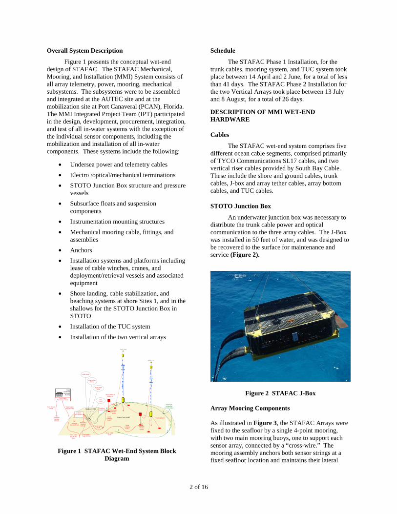
separation at the specified distance of 280 (+20 – 0) yards.
Figure 3 STAFAC Primary Mooring Configuration
The four-leg mooring depicted in Figure 4 is designed to hold two “false bottom” (main mooring) buoys as stationary as possible in all currents. Each buoy is made of syntactic foam with 12,000lb of buoyancy. A wire rope mooring line secures each anchor to each main mooring buoy. A “cross-wire” permanently holds the two main mooring buoys a fixed distance apart (to maintain accurate array separation). A wire rope counterweight cable and counterweight anchor was installed through each main mooring buoy via a center channel. A stopper was fastened to the counterweight cable to mechanically set the depth of the array. This arrangement allows for easy lifting of the array for servicing, with automatic repositioning when it is lowered back into position.
Figure 4 Nominal Mooring Anchor Positions
Figure 5 provides illustrations and photos for the mooring anchors. Several anchor configurations were considered, but the combination of Bruce and clump anchor was selected to provide the vertical weight and horizontal embedment required to secure the steep angle for the wire lines and the buoyancy of the main mooring buoys.
Figure 5 Bruce and Clump Main Mooring
Anchors
Figure 6 provides a photo and illustration of the Umbilical Anchor for each of the two vertical riser cables. The two riser cables are supported by the subsurface buoys and provide power and optical communication to the two vertical arrays.
Figure 6 Umbilical Anchors
Main Mooring Buoys
The two Main Mooring Buoys provide upward tension to stabilize the 4-point Primary Mooring and to support the Counterweight cables and anchors. They also provide positioning through-points for the Counterweight Cables to secure, via the Counterweight Stoppers, the two HGMS Arrays, as shown in Figure 7.
SL17 ARRAY CABLE
Fish plate w/ third hole for load transfers
Dyna-grip w/ rods for riser cable
Torque balanced Umbilical riser cable
Dyna-grip w/ rods for array cable
Rotating bale arm
Breakout bottle and anode
Structural frame and rail wheels for umbilical anchor (8 kip dry, 6560 wet)
North
2362,-4090 ft
-2362,-4090 ft
0,0 ft
2362, 4930 ft
-2362, 4930 ft
-1128,-411 ft 1128, 1248 ft
0,840 ft
STAFAC Baseline Mooring ConfigurationAnchor Locations
30o
20o
North
2362,-4090 ft
-2362,-4090 ft
0,0 ft
2362, 4930 ft
-2362, 4930 ft
-1128,-411 ft 1128, 1248 ft
0,840 ft
STAFAC Baseline Mooring ConfigurationAnchor Locations
30o
20o
MOORING ANCHORS
UMBILICAL BUOY (8 kip OHDB buoy)
UMBILICAL ANCHOR W/ SPLICE FROM UMBILICAL TO ARRAY INTERCONNECT CABLE
NILSPIN MOORING LEGS
FLOATED S-TETHER W/ CABLE FLOATS AND WEIGHTS
SHALLOW WBO BUOY (12kip OHDB buoy)
ARRAY
SYNTACTIC MOORING FLOTATION (3X6’DX7’L cylinders, 25 kip buoyancy)
COUNTER WEIGHT LINE W/ STOPPER
COUNTER WEIGHT
CROSS WIRE (NILSPIN)
TORQUE BALANCED, ARMORED UMBILICAL
TYCO SL17 CABLE TO J-BOX
4 of 16
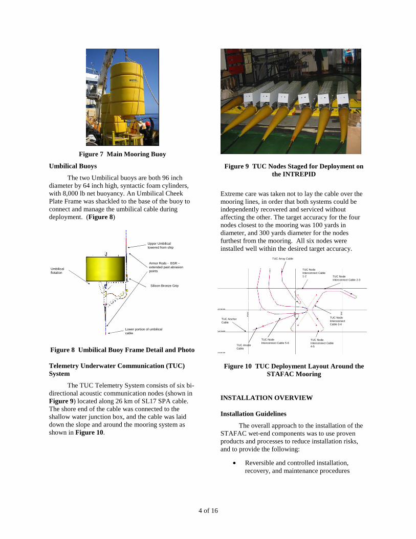
Figure 7 Main Mooring Buoy
Umbilical Buoys
The two Umbilical buoys are both 96 inch diameter by 64 inch high, syntactic foam cylinders, with 8,000 lb net buoyancy. An Umbilical Cheek Plate Frame was shackled to the base of the buoy to connect and manage the umbilical cable during deployment. (Figure 8)
Figure 8 Umbilical Buoy Frame Detail and Photo
Telemetry Underwater Communication (TUC) System
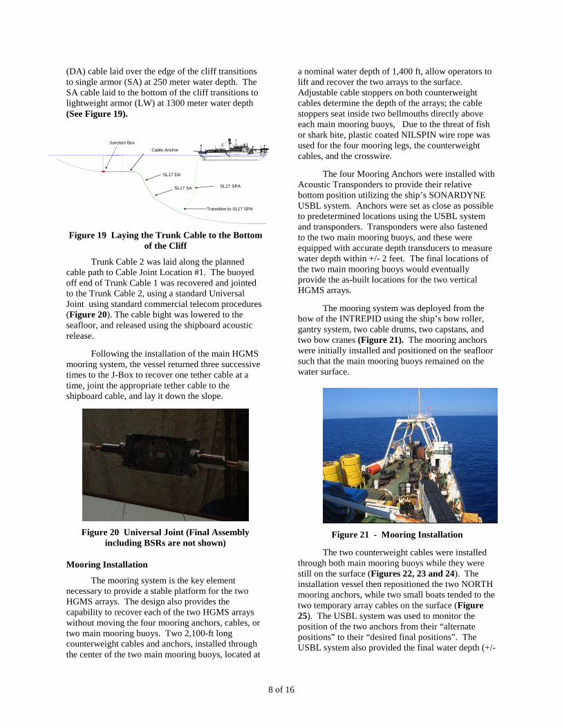
The TUC Telemetry System consists of six bi-directional acoustic communication nodes (shown in Figure 9) located along 26 km of SL17 SPA cable. The shore end of the cable was connected to the shallow water junction box, and the cable was laid down the slope and around the mooring system as shown in Figure 10.
Figure 9 TUC Nodes Staged for Deployment on the INTREPID
Extreme care was taken not to lay the cable over the mooring lines, in order that both systems could be independently recovered and serviced without affecting the other. The target accuracy for the four nodes closest to the mooring was 100 yards in diameter, and 300 yards diameter for the nodes furthest from the mooring. All six nodes were installed well within the desired target accuracy.
Figure 10 TUC Deployment Layout Around the STAFAC Mooring
INSTALLATION OVERVIEW
Installation Guidelines
The overall approach to the installation of the STAFAC wet-end components was to use proven products and processes to reduce installation risks, and to provide the following:
• Reversible and controlled installation, recovery, and maintenance procedures
Upper Umbilical lowered from ship
Umbilical flotation
Lower portion of umbilical cable
Armor Rods - BSR –extended past abrasion points
Silicon Bronze Grip
TUC Array Cable
TUC Node Interconnect Cable 1-2 TUC Node
Interconnect Cable 2-3
TUC Node Interconnect Cable 3-4
TUC Node Interconnect Cable 4-5
TUC Node Interconnect Cable 5-6
TUC Anchor Cable
TUC Anode Cable

5 of 16
• Phased installation/recovery events (to provide “operational off-ramps” in case of unforeseen delays due to weather or equipment malfunctions)
• Duplicate components (where redundancy is warranted), and selected spare parts (for single point failures)
Top priorities for these operations are:
• Personnel Safety • Minimize risks to the Bahamas environment
(in particular, the coral reefs)
Installation Order
The STAFAC Telecom cables, mooring system, and TUC cable system were installed in the following order:
1. Mobilization
2. Ground Cable and Cathode
3. Trunk Segment 1 Landing and Lay
4. J-Box and Tethers
5. Trunk Segment 2
6. Deep Water Joint
7. Primary Mooring
8. North Array and Umbilical Cables
9. South Array and Umbilical Cables
10. TUC Cable and Array
11. Demobilization
Navigation and Positioning
MAKAI Ocean Engineering provided cable engineering and cable and vessel navigation for the STAFAC cable installation operation. MAKAIPLAN and MAKAILAY have become the industry standard software programs for creating seafloor cable routes, ship installation routes and speed, versus percent slack and the given bathymetry, as illustrated in Figure 11. MAKAIPLAN provides a route planning list (RPL) and straight line diagrams (SLD).
Figure 11. MakaiPlan Deployment of Cable and In-Line Nodes
The STAFAC installation relied on real-time estimates of the 3-dimensional positions of key components, (anchors for example), to help guide the installation. These position estimates were determined using the shipboard SONARDYN Ultra-Short Baseline (USBL) tracking system, upgraded to improve the positioning accuracy required to install the STAFAC components. The INTREPID currently has the following USBL system installed:
Sonardyn - Model AM-7707 Version 6 USBL Transponder - Type 7970 Directional Super Sub Mini Transponder
SITE PREPARATIONS
Shore Landing Site 1
Site 1 was prepared for landing both the Ground and Trunk Cables, with a separate team performing these tasks. Preliminary steps, including offshore surveys and planting of two cable anchors were performed in August 2007.
Junction Box Site
The J-Box area was prepared in 2007, including shallow water surveys and, in August 2007, the installation of five cable, four J-Box, and four Recovery Vessel Mooring Anchors. Figure 12 presents an illustration of the STAFAC layout.

6 of 16
Figure 12 STAFAC System Location
PHASE 1 STAFAC TRUNK CABLE, MOORING SYSTEM, AND TUC SYSTEM INSTALLATION
C/S INTREPID
The Cable Ship (C/S) INTREPID was chartered from IT INTERNATIONAL TELECOM, based in Montreal, Canada. The vessel is home ported in Halifax, Nova Scotia, Canada. The vessel is a purpose built commercial telecom vessel equipped to install, recover, and repair cable systems in water depths up to 16,000 feet. (Figure 12)
Figure 13 C/S INTREPID
Mobilization
The STAFAC installation vessel and system equipment mobilization was staged at a Port Canaveral, Florida Pier. The C/S INTREPID
transited to TYCO, Newington New Hampshire, to load the 250km, SL17 submarine cable, for four days. The vessel then transited to Port Canaveral Florida, to load the STAFAC mooring components, and the J-Box, for an additional three days. During the transit to AUTEC Site 1, the Intrepid IT Joint team completed the Trunk Tether to Trunk Segment 2 Cable Universal Joint (UJ). Following the installation of the shore end cables, the submarine cables, the J-Box, and the Mooring System, the vessel returned to PCAN to load the TUC system.
Site 1 Shore Landing
The AUTEC Site 1 area from the beach to the escarpment is made up of sandy areas with intermittent coral heads. These coral heads range in size from less than one meter to ten meters in diameter. The deployment of the STAFAC trunk cable and ground cable was conducted in such a manner as to avoid these coral heads and to maintain their current conditions, according to applicable NEPA requirements.
Figure 14 - Shore End Pulling Operating
The cable paths were selected using the survey information and on-site diver surveys conducted by the US Navy Underwater Construction Team 1. To transition the cable from the lagoon to the steep escarpment, the shore cables were laid through an existing opening in the reef, and anchored to the seafloor using rock-bolts epoxied into the seafloor.

7 of 16
The same procedure was used to install the Ground Cable and Trunk Cable, except that divers anchored the Trunk cable to the seafloor near the edge of the cliff, prior to laying the sea cable.
Trunk Cable Segment #1 Installation
After the cable was secured to the cable anchors on the seafloor, the INTREPID began laying the 142-km long Trunk Cable 1, down the slope as directed by the MAKAILAY system and operators, and IT vessel personnel (Figure 16), to the Deep Joint Site in the South TOTO Cul-de-Sac, (labeled Cable Joint Location #1). The end of the cable was capped, lowered to the seafloor, and buoyed-off on the surface, for later retrieval. The vessel speed during the cable laying varied between 1 and 3 knots.
Figure 15 - Deployment of Ground Cable and Cathode to Seafloor
Figure 16 - IT INTREPID Deployment of Trunk Cable Down Slope
J-Box And Trunk Cable Segment #2 Installation
Following the installation of Trunk Cable Segment 1, the vessel transited to the J-Box location. The J-Box was installed in 50-ft of water in order that it can be recovered and serviced when necessary. Twelve months prior to the installation, the UCT1 divers surveyed the J-Box site, and installed the vessel mooring anchors (not used by the INTREPID, which is dynamically positioned), J-Box anchors, and cable anchor bolts.
The cable ends were capped to prevent water intrusion, and were marked for identification and recovery for the installation of the HGMS and the TUC seafloor cables. Each cable was later individually recovered and jointed to the system cables using a commercial UJ cable joint kit.
Figure 17 J-Box Deployment
Figure 18 J-Box Lowered to the Seafloor
The South TOTO location, with a predominant 200 yard wide sand chute, was selected to minimize long-term wear on the cable and to avoid damaging any significant seafloor features. The double armor
S TERN L I G HT
Cable anchor
8 of 16
(DA) cable laid over the edge of the cliff transitions to single armor (SA) at 250 meter water depth. The SA cable laid to the bottom of the cliff transitions to lightweight armor (LW) at 1300 meter water depth (See Figure 19).
Figure 19 Laying the Trunk Cable to the Bottom of the Cliff
Trunk Cable 2 was laid along the planned cable path to Cable Joint Location #1. The buoyed off end of Trunk Cable 1 was recovered and jointed to the Trunk Cable 2, using a standard Universal Joint using standard commercial telecom procedures (Figure 20). The cable bight was lowered to the seafloor, and released using the shipboard acoustic release.
Following the installation of the main HGMS mooring system, the vessel returned three successive times to the J-Box to recover one tether cable at a time, joint the appropriate tether cable to the shipboard cable, and lay it down the slope.
Figure 20 Universal Joint (Final Assembly
including BSRs are not shown)
Mooring Installation
The mooring system is the key element necessary to provide a stable platform for the two HGMS arrays. The design also provides the capability to recover each of the two HGMS arrays without moving the four mooring anchors, cables, or two main mooring buoys. Two 2,100-ft long counterweight cables and anchors, installed through the center of the two main mooring buoys, located at
a nominal water depth of 1,400 ft, allow operators to lift and recover the two arrays to the surface. Adjustable cable stoppers on both counterweight cables determine the depth of the arrays; the cable stoppers seat inside two bellmouths directly above each main mooring buoys, Due to the threat of fish or shark bite, plastic coated NILSPIN wire rope was used for the four mooring legs, the counterweight cables, and the crosswire.
The four Mooring Anchors were installed with Acoustic Transponders to provide their relative bottom position utilizing the ship’s SONARDYNE USBL system. Anchors were set as close as possible to predetermined locations using the USBL system and transponders. Transponders were also fastened to the two main mooring buoys, and these were equipped with accurate depth transducers to measure water depth within +/- 2 feet. The final locations of the two main mooring buoys would eventually provide the as-built locations for the two vertical HGMS arrays.
The mooring system was deployed from the bow of the INTREPID using the ship’s bow roller, gantry system, two cable drums, two capstans, and two bow cranes (Figure 21). The mooring anchors were initially installed and positioned on the seafloor such that the main mooring buoys remained on the water surface.
Figure 21 - Mooring Installation
The two counterweight cables were installed through both main mooring buoys while they were still on the surface (Figures 22, 23 and 24). The installation vessel then repositioned the two NORTH mooring anchors, while two small boats tended to the two temporary array cables on the surface (Figure 25). The USBL system was used to monitor the position of the two anchors from their “alternate positions” to their “desired final positions”. The USBL system also provided the final water depth (+/-
STER N L IGH T
SL17 DA
Junction BoxCable Anchor
SL17 SA
Transition to SL17 SPA
SL17 SPA

9 of 16
2 feet) and lateral position (+/- 5 feet) of the main mooring buoys.
Figure 22 - Counterweight cable Reeved through the Main Mooring Buoy
Figure 23 - Counterweight Cable Pulled Through the Main Mooring Buoy
Figure 24 - Both Counterweight Cables Installed
Figure 26 illustrates the beginning of the mooring anchor re-positioning operation. Two small support vessels were employed to tend the temporary array cables on the surface while the INTREPID repositioned the two North mooring anchors. A small boat was used to shackle the two temporary array cables to the top of the two counterweight
cables. These were comprised of (i) 900 ft long ½-in Spectra, (ii) 450 ft of ½-in wire rope, (iii) a 4 Kip temporary buoy, (iv) 100 feet of ¾-in wire rope, and (v) a surface float.
Figure 25 Mooring Anchor Repositioning
The INTREPID recovered the two North mooring anchor crown buoys individually and repositioned the seafloor anchors to the estimated final position on the seafloor. To minimize the strain on the mooring system wire rope sections, the anchors were alternately repositioned 1/3 the total estimated distance (Figure 26).
Figure 26 INTREPID Lifts Mooring Anchors off of the Seafloor
Table 1 presents the lateral position offsets for the two main mooring buoys, the four mooring anchors, and the center origin, and Table 2 presents the water depth for the two main mooring buoys. All of the mooring components were installed within the desired tolerance.
Table 1 Mooring Position Offsets (ft)
Item Delta North
Delta East
Total Radial Offset
N Buoy -0.91 23.83 23.84 S Buoy 2.74 10.02 10.38 Origin 0.92 16.92 16.94
NE Anchor 24.11 0.33 24.11 NW Anchor -7.61 8.39 11.33 SE Anchor -16.29 12.91 20.78

10 of 16
SW Anchor 14.99 -16.85 22.56
Table 2 Main Mooring Buoy Depth (ft)
Name Desired Actual Variance N Buoy 1,400 1,391 8 S Buoy 1,400 1,391 8
After the anchors were re-positioned and the Main Mooring Buoys locations were confirmed within the desired target depth and position accuracies, the INTREPID recovered the three Crown Buoys, and, using the INTREPID’s acoustic release system and a working line, laid the crown lines onto the seafloor.
Umbilical Cable Installation
The umbilical cables, anchors, and buoys were deployed from the stern of the INTREPID using both the plow and cable decks, the linear cable engine, the 3-meter diameter bow sheave, the A-Frame and two working lines, and the 5-Ton stern crane.
The Umbilical Cables were installed beginning with the North system, followed by the South System. The installation began at the J-Box with a UJ to the J-Box North Umbilical Tether Cable; the umbilical anchor and buoy were staged on the plow deck in preparation for deployment (Figure 27).
Figure 27 Umbilical Anchor and Cable Staged for Deployment
Figure 28 shows the Umbilical Anchor being deployed.
Figure 28 Umbilical Anchor Deployment
Figure 29 presents the required umbilical anchor target accuracy, which is an ellipse. The USBL acoustic transponder provided the position of the anchor on the seafloor.
EAST
UMBILICAL ANCHOR
Figure 29 Umbilical Anchor Target Ellipse
(Dimensions in Feet)
When the umbilical cable payout approached within 50 feet of the umbilical buoy, the vessel and cable payout was stopped. The vessel held station while the Umbilical Buoy was staged on the cable deck (Figure 30). The Umbilical Anchor was approximately 850 feet above the seafloor at this point in the installation operation.
Cable Stopper to Deck
Umbilical Cable Fastened to Cheek Plates
Umbilical Bu
11 of 16
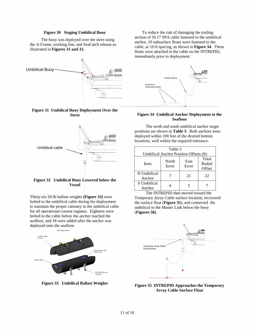
Figure 30 Staging Umbilical Buoy
The buoy was deployed over the stern using the A-Frame, working line, and SeaCatch release as illustrated in Figures 31 and 32.
Figure 31 Umbilical Buoy Deployment Over the
Stern
Figure 32 Umbilical Buoy Lowered below the Vessel
Thirty-six 50-lb ballast weights (Figure 33) were bolted to the umbilical cable during the deployment to maintain the proper catenary in the umbilical cable for all operational current regimes. Eighteen were bolted to the cable before the anchor reached the seafloor, and 18 were added after the anchor was deployed onto the seafloor.
Figure 33 Umbilical Ballast Weights
To reduce the risk of damaging the trailing section of SL17 SPA cable fastened to the umbilical anchor, 10 subsurface floats were fastened to the cable, at 10-ft spacing, as shown in Figure 34. These floats were attached to the cable on the INTREPID, immediately prior to deployment.
Figure 34 Umbilical Anchor Deployment to the Seafloor
The north and south umbilical anchor target positions are shown in Table 3. Both anchors were deployed within 100 feet of the desired bottom locations, well within the required tolerance.
Table 3 Umbilical Anchor Position Offsets (ft)
Item North Error
East Error
Total Radial Offset
N Umbilical Anchor 7 21 22
S Umbilical Anchor 4 5 7
The INTREPID then moved toward the Temporary Array Cable surface location, recovered the surface float (Figure 35), and connected the umbilical to the Master Link below the buoy (Figures 36).
Figure 35 INTREPID Approaches the Temporary Array Cable Surface Float
Umbilical cable
Umbilical Buoy
Small 50 lb Subsurface Buoys
Temporary Array Cable Surface Buoy
5” STEEL BAR STOCK
3/8” Silicon Bronze Fasteners
Polyurethane cable clamps inset
Radius edges
Wet weight: 50 lbs
Umbilical Buoy

12 of 16
Figure 36 Umbilical Cable Shackled to Temporary Array Cable
TUC System Cable Installation
The TUC cable system was installed following the completion of the North and South Umbilical cable system. The vessel returned to PCAN to load the TUC system and returned to the J-Box location to begin the installation.
The TUC cables, nodes, and anchors, were deployed from the stern of the INTREPID using the plow and cable decks, the linear cable engine, and the 10-ft diameter bow sheave. The installation began with a UJ to the J-Box TUC Tether Cable. The TUC nodes were staged on the cable deck in preparation for deployment.
Figure 36 presents the lay-down plan for the TUC cable and nodes. The circuitous layout was necessary to eliminate any interference from the mooring legs and anchors.
Because the TUC nodes had eccentric instrument packages, they could not be deployed through the vessel’s LCE and it was necessary to bight around the LCE to deploy each node. This required less than 15 minutes per node (Figure 37). The vessel crew and project team personnel practiced several times with a mock-up TUC node prior to the actual deployment to refine the deployment procedure, and all nodes were successfully and safely deployed from the ship.
Figure 37 TUC Cable Deployed with Capstan and Node Passes Around LCE
Before deploying the TUC nodes, SST personnel ensured that the four magnesium alloy corrosive bolts were properly installed on each of the TUC Node Shrouds prior to deployment. The corrosive bolts dissolved within 36 hours of deploying each TUC node into the seawater, releasing the shroud, and hydrophone and 25 foot long hydrophone cable
Because of the higher wind conditions (15-20 knot winds), experienced during the installation of the TUC system, the vessel had to maintain a heading between 45 and 135 degrees during the entire operation. It was necessary to lay the cable well beyond a 90 degree crab angle on the stern roller, and for some of the installation operations, the cable was laid directly behind and under the ship. Vessel speed for extreme cable deployment angles greater than 90 degrees was limited to ½ knot
Table 4 provides the target accuracy requirement and actual offset on the seafloor for the TUC system nodes. All six TUC nodes were well within the required accuracy.
Table 4 TUC Node Position Offsets (ft)
Item Along Track
Cross Track
Total Radial Offset
Required Target
Accuracy Node 1 217 -20 218 300 Node 2 -44 53 69 300 Node 3 -158 -119 198 600 Node 4 20 19 27 300 Node 5 -19 -7 21 300 Node 6 -27 -78 83 600
HGMS ARRAY CABLE INSTALLATION
HGMS A-Frame
To install and also to recover and maintain the HGMS array, project team personnel decided that it would be beneficial to design and fabricate a purpose-built deployment system that would be compatible with most ship-of-opportunity supply-type vessels.
SST reviewed all of the project requirements and designed the 45-ft tall, 30-ft wide A-Frame (Figure 38), that included two winches and working lines, one deck winch, and two 35-ft tall TBCA Stands (Figure 39) to stage the array. The A-Frame was designed to be stored and transportable on two 40-ft ISO flat-racks.
Umbilical cable
Temporary Buoy
Umbilical Buoy
Counter Weight Anchor
Main Mooring Buoy
Umbilical Anchor
DOOR
HATCH
W.T.D.
WT STORES
HINGED
UP
CAPSTAN (P&S)
0
UP
(EXERCISE ROOM)
20
L.C.E. CONTROL ROOM
TAUT WIRE ROOM
CREWSRECREATION
ROOM
E/R VENT
10
W.T.D.
15
CATERERS MESS.
GALLEY
LINEAR CABLE ENGINE
CREWS MESS.
25
HATCH
ALLEY
30
DN
SHIPSOFFICE
FILLINGSTATION
W.T.D.
FO
INCINERATOR ROOM
CON. ROOM
G.T.D.
ENGINECASING
P.OS. MESS
STONKER
35 40
OFFICECOMPUTER
DUTYMESS
FILLING
W.T.D.
STATION
FO.
LKR
AIR LOCKDW.
45
CASINGENGINE
CO2 ROOM
UP
DN
ELECTTLT
AIR
COMPACTOR
P.OS. REC ROOM.
W.T.D.
TLT
UP
DN
50 55 60
EQUALISER / JOINTING TENT
CENTERCASTLECABLE TROUGH
EL EVATED
65 70
DOOR
HATCH
W.T.D.
WT STORES
HINGEDCAPSTAN (P&S)
0
UP
20
L.C.E. CONTROL ROOM
10
W.T.D.
15
CREW

13 of 16
Figure 38 HGMS 45-ft Tall A-Frame
The 900-ft long HGMS arrays were designed with “pick points” every 30 feet, to match the “stroke” for both working lines on the A-Frame. Therefore the 900-ft long arrays required approximately thirty 30-ft long lifts to deploy.
Figure 39 Two TBCA Frames
M/V DOMINATOR
The M/V DOMINATOR is a 240-ft long oil-field supply vessel, with a large open aft deck, and a Class 2 Dynamic Positioning (DP-2) system. The DP-2 system indicates that the vessel possesses fully redundant station keeping capability. This specification is required in order for the vessel to remain on station for up to three consecutive days, within a 25-ft watch circle, while each array is installed. The vessel is home-ported in Fourchon, Louisiana. Figure 40 is a photo of the vessel as it first arrived at Port Canaveral.
Figure 40 M/V DOMINATOR
Mobilization in July 2008
The STAFAC installation vessel and system equipment mobilization was staged at a Port Canaveral, Florida Pier. One hundred and twenty-five tons of equipment and array systems were shipped to the Navy Base at Port Canaveral, Florida. All of the equipment was loaded and secured to the vessel in four days. All of the installation equipment, including the A-Frame and winches, was load tested to ABS standards to ensure a safe installation operation. Figure 41 presents a deck layout for the installation vessel.
Figure 41 Vessel Deck Layout
#1 A-Frame
#2 TBCA Stands w/ TBCA’s hanging inside
#3 – 20’ Test Van
#15 - Crane
#9- 40’ Array Van
#6 – Skagit G-70 #14 – Pullmaster Winch
#10 – SST 40’ Van#13 - RIB#4 - HPU#5- Control Console
#7- array flakedin this area
#11- Old Buoys
14 of 16
HGMS Array Installation
The INTREPID transited from PCAN to the array installation site in two days. Upon arrival, it became evident that the surface floats were missing. The divers spent three days looking for the subsurface floats, but found only the South float. Divers also determined that the South float had also lowered from the original depth at installation of 100 feet to approximately 160 feet, below diver depth of 99 feet (for SCUBA according to Corp of Engineer Regulations). Because of the increased depth, divers were unable to recover the South float. A small ROV was transported to the ship, and within four hours, was able to locate both subsurface floats, and with the aid of divers, to recover the 100-ft wire rope lifting line. Upon inspection, all three surface floats for both temporary subsurface buoys were still fastened to the ends of the 100-ft lifting wires. Five of the six floats were deflated and appeared to have been damaged by a propeller or bitten by a shark.
The South and North HGMS arrays were virtually identical. Some of the acoustic elements were located or spaced differently, but both arrays were installed using the same approach. The installation began with the South Array, followed by the North Array.
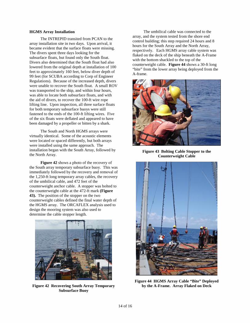
Figure 42 shows a photo of the recovery of the South array temporary subsurface buoy. This was immediately followed by the recovery and removal of the 1,250-ft long temporary array cables, the recovery of the umbilical cable, and 472 feet of the counterweight anchor cable. A stopper was bolted to the counterweight cable at the 472-ft mark (Figure 43). The position of the stopper on the two counterweight cables defined the final water depth of the HGMS array. The ORCAFLEX analysis used to design the mooring system was also used to determine the cable stopper length.
Figure 42 Recovering South Array Temporary Subsurface Buoy
The umbilical cable was connected to the array, and the system tested from the shore end control building; this step required 24 hours and 8 hours for the South Array and the North Array, respectively. Each HGMS array cable system was flaked on the deck of the ship beneath the A-Frame with the bottom shackled to the top of the counterweight cable. Figure 44 shows a 30-ft long “bite” from the lower array being deployed from the A-frame.
Figure 43 Bolting Cable Stopper to the Counterweight Cable
Figure 44 HGMS Array Cable “Bite” Deployed by the A-Frame. Array Flaked on Deck

15 of 16
Load Transfer Links (Figure 45) were used throughout the length of the HGMS arrays to lift, transfer loads, and deploy the array cable.
Figure 45 Load Transfer Link
Figure 46 shows the deployment of the Horizontal HFA and the 29-ft tall Twisted Bi-Cone Array (TBCA) from the A-Frame. The two TBCAs for both arrays were transported vertically on the ship, in the two TBCA stands. The TBCAs were each transferred from the TBCA stand to the A-Frame using a 55-ton crane. Figure 47 illustrates the lowering and deployment of the HFA, and a load transfer to the TBCA working line.
Figure 46 TBCA and HFA Installation from the A-Frame
Figure 47 HFA Lowered into the Water and Load Transferred to the TBCA
Figure 48 presents the TBCA being lowered into the water from the A-Frame. A small boat was used intermittently to assist with the installation.
Figure 48 TBCA Lowered Into the Water
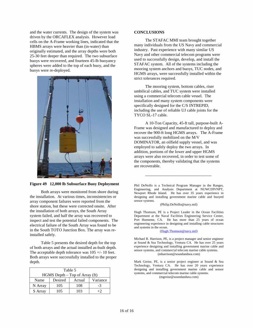
Figure 49 presents the installation of the final 12,000 lb Subsurface buoy, and the 300 lb WBO buoy. The deployment of the subsurface buoy was the highest deployment load experienced for the installation (20,000 lbs). When the subsurface buoy was lowered into the water, the deployment load dropped to less than 2,000 lbs.
The final depth of the two Arrays was directly dependent on the height and buoyancy of the Main Mooring Buoys, the stopper position and length of the counterweight cable above the main mooring buoy, the weight in water of the HGMS arrays, the buoyancy of the Subsurface buoy and WBO buoy,
Array Cable(Under Load)
Umbilical Cable(Under Load)
16 of 16
and the water currents. The design of the system was driven by the ORCAFLEX analysis. However load cells on the A-Frame working lines, indicated that the HBMS arrays were heavier than (in-water) than originally estimated, and the array depths were both 25-30 feet deeper than required. The two subsurface buoys were recovered, and fourteen 45-lb buoyancy spheres were added to the top of each buoy, and the buoys were re-deployed.
Figure 49 12,000 lb Subsurface Buoy Deployment
Both arrays were monitored from shore during the installation. At various times, inconsistencies or array component failures were reported from the shore station, but these were corrected onsite. After the installation of both arrays, the South Array system failed, and half the array was recovered to inspect and test the potential failed components. The electrical failure of the South Array was found to be in the South TOTO Junction Box. The array was re-installed safely.
Table 5 presents the desired depth for the top of both arrays and the actual installed as-built depth. The acceptable depth tolerance was 105 +/- 10 feet. Both arrays were successfully installed to the proper depth.
Table 5 HGMS Depth – Top of Array (ft)
Name Desired Actual Variance N Array 105 108 -3 S Array 105 103 +2
CONCLUSIONS
The STAFAC MMI team brought together many individuals from the US Navy and commercial industry. Past experience with many similar US Navy and other commercial telecom programs were used to successfully design, develop, and install the STAFAC system. All of the systems including the mooring system anchors and buoys, TUC nodes, and HGMS arrays, were successfully installed within the strict tolerances required.
The mooring system, bottom cables, riser umbilical cables, and TUC system were installed using a commercial telecom cable vessel. The installation and many system components were specifically designed for the C/S INTREPID, including the use of reliable UJ cable joints for the TYCO SL-17 cable.
A 10-Ton Capacity, 45-ft tall, purpose-built A-Frame was designed and manufactured to deploy and recover the 900-ft long HGMS arrays. The A-Frame was successfully mobilized on the M/V DOMINATOR, an oilfield supply vessel, and was employed to safely deploy the two arrays. In addition, portions of the lower and upper HGMS arrays were also recovered, in order to test some of the components, thereby validating that the systems are recoverable.
________________________________
Phil DeNolfo is a Technical Program Manager in the Ranges, Engineering, and Analysis Department at NUWCDIVNPT, Newport Rhode Island. He has over 35 years experience in designing and installing government marine cable and buoyed sensor systems.
([email protected]) Hugh Thomson, PE is a Project Leader in the Ocean Facilities Department at the Naval Facilities Engineering Service Center, Port Hueneme, CA. He has more than 25 years of ocean engineering experience in designing and installing cable structures and systems in the ocean.
Michael R. Harrison, PE, is a project manager and senior engineer at Sound & Sea Technology, Ventura CA. He has over 25 years experience designing and installing government marine cable and sensor systems, and commercial telecom marine cable systems.
([email protected]) Mark Greise, PE, is a senior project engineer at Sound & Sea Technology, Ventura CA. He has over 20 years experience designing and installing government marine cable and sensor systems, and commercial telecom marine cable systems.
![Toto the Best of Toto Full Band Score[1]](https://static.fdocuments.us/doc/165x107/54580b1fb1af9fbd038b46a4/toto-the-best-of-toto-full-band-score1.jpg)