SOURCE TEST PROCEDURE ST-7 ORGANIC COMPOUNDS - BAAQMD - Home
21
Bay Area Air Quality Management District Amended April 15,1992 ST-7-1 SOURCE TEST PROCEDURE ST-7 ORGANIC COMPOUNDS REF: Regulation 8 1. APPLICABILITY 1.1 This procedure is used to quantify emissions of organic compounds. It is applicable to the determination of compliance with Regulation 8. 1.2 The combustion technique detailed in ST-7 is not applicable when carbon dioxide constitutes over 85%, on a molar basis, of the total carbon (organic plus inorganic, as C 1 ), in the sample. 1.3 The use of a flame ionization detector (FID) for direct measurement of organic compounds may be used when carbon dioxide constitues over 85%, on a molar basis, of the total carbon in the sample. 2. PRINCIPLE 2.1 Combustion Technique: A continuous sample of effluent is passed through a combustion tube. The combusted sample is conditioned to remove water and particulate. The continuously combusted sample is analyzed for Total Carbon (TC) using a non-dispersive infrared (NDIR) CO 2 analyzer. At the same time, a continuous sample of effluent is conditioned to remove water and particulate material. This sample which has bypassed the combustion tube is analyzed to determine the background CO 2 , CO, and methane concentrations which are subtracted from the TC value to determine the non-methane organic carbon (NMOC) concentration. The background CO 2 concentration is measured using the same NDIR as that used to measure TC. 2.2 FID Direct Measurement: A continuous sample of effluent is conditioned to remove water and particulate material. The conditioned sample is analyzed for total hydrocarbons (THC) by FID. NMOC concentration is calculated by subtracting the methane concentration from the THC concentration. 2.3 The methane content of the sample is determined either (A) by filling an evacuated cylinder with sample for subsequent gas chromatographic analysis or (B) by directing a portion of the conditioned sample through a bed of activated carbon to remove NMOC and then into a FID. 3. RANGE AND SENSITIVITY 3.1 The minimum measurable concentration of carbon dioxide is 10 ppm if the appropriate NDIR cell is used. 3.2 The maximum concentration of organic compounds for which the combustion technique in this procedure is applicable is 5% when the appropriate NDIR cell is used. 3.3 The minimum sensitivity of the NDIR is 2% of full scale. 3.4 Use of the combustion technique requires a molar concentration ratio of oxygen to VOC of 5:1 or greater.
Transcript of SOURCE TEST PROCEDURE ST-7 ORGANIC COMPOUNDS - BAAQMD - Home

Bay Area Air Quality Management District Amended April 15,1992ST-7-1
SOURCE TEST PROCEDURE ST-7
ORGANIC COMPOUNDS
REF: Regulation 8
1. APPLICABILITY
1.1 This procedure is used to quantify emissions of organic compounds. It isapplicable to the determination of compliance with Regulation 8.
1.2 The combustion technique detailed in ST-7 is not applicable when carbondioxide constitutes over 85%, on a molar basis, of the total carbon (organicplus inorganic, as C1), in the sample.
1.3 The use of a flame ionization detector (FID) for direct measurement oforganic compounds may be used when carbon dioxide constitues over 85%,on a molar basis, of the total carbon in the sample.
2. PRINCIPLE
2.1 Combustion Technique: A continuous sample of effluent is passed througha combustion tube. The combusted sample is conditioned to remove waterand particulate. The continuously combusted sample is analyzed for TotalCarbon (TC) using a non-dispersive infrared (NDIR) CO 2 analyzer. At thesame time, a continuous sample of effluent is conditioned to remove waterand particulate material. This sample which has bypassed the combustiontube is analyzed to determine the background CO 2, CO, and methaneconcentrations which are subtracted from the TC value to determine thenon-methane organic carbon (NMOC) concentration. The background CO 2concentration is measured using the same NDIR as that used to measureTC.
2.2 FID Direct Measurement: A continuous sample of effluent is conditioned toremove water and particulate material. The conditioned sample is analyzedfor total hydrocarbons (THC) by FID. NMOC concentration is calculated bysubtracting the methane concentration from the THC concentration.
2.3 The methane content of the sample is determined either (A) by filling anevacuated cylinder with sample for subsequent gas chromatographicanalysis or (B) by directing a portion of the conditioned sample through abed of activated carbon to remove NMOC and then into a FID.
3. RANGE AND SENSITIVITY
3.1 The minimum measurable concentration of carbon dioxide is 10 ppm if theappropriate NDIR cell is used.
3.2 The maximum concentration of organic compounds for which thecombustion technique in this procedure is applicable is 5% when theappropriate NDIR cell is used.
3.3 The minimum sensitivity of the NDIR is 2% of full scale.
3.4 Use of the combustion technique requires a molar concentration ratio ofoxygen to VOC of 5:1 or greater.

MOP Vol. IV. ST-7 Organic Compounds
Bay Area Air Quality Management District Amended April 15,1992ST-7-2
3.5 The minimum measurable concentration of THC by FID is 5 ppmv wheninterferences are not present.
3.6 The minimum sensitivity of the FID is 2% of full scale.
4. INTERFERENCES
4.1 Combustion Technique:Negative bias may occur due to reaction of highlyreactive organics (e.g., aldehydes or acids) with internal surfaces or if thecondensation point of the sample is above the condenser temperature.Combustion at the emission point, prior to condenser and the use of theminimum probe to combustor tubing length, greatly reduces this bias.
4.2 Combustion Technique: High concentrations or widely varyingconcentrations of methane, carbon monoxide or carbon dioxide mayadversely affect the accuracy of this procedure for the measurement of theorganic compounds present. Alternate methods may be used upon priorapproval by the Source Test Section Manager.
4.3 FID Direct Measurement: Response factors vary be tween hydrocarbons.Propane used as a span gas minimizes this variability. The measurement ofchlorinated hydrocarbons, in some instances, may require the use of analternative span gas. Use of an alternative span gas must be approved bythe Source Test Manager.
4.4 FID Methane Measurement: The activated charcoal scrubber adsorbs non-methane hydrocarbons from sample gas before its subsequent analysis byFID. Previous contamination or unclean activated charcoal in this scrubbercan lead to the determination of erroneously high levels of methane. Thisproblem is obviated by establishing a zero methane base-line response.Methane determination requires that the response time must be sufficient toallow for the residence time of sample gas in the carbon adsorber.
5. APPARATUS
5.1 Carbon dioxide analyzer. Use a non-dispersive infrared gas analyzer (inaccordance with ST-5).
5.2 Carbon monoxide analyzer. Use a non-dispersive infrared gas analyzer (inaccordance with ST-6).
5.3 Flame ionization detector .
5.4 Chart recorder. Record the continuous output from each analyzer.
5.5 Sample conditioning, zero air, and span gas system. Assemble this systemas shown in Figure 7-1. Sample conditioning system shall provide a dry,particulate-free gas flow to the instrument. The zero-air system shall provideclean, dry CO2 free air for instrument calibration. The span-gas systemshall provide known concentration of the appropriate gas for use incalibrating the analyzers. Except as specified, all materials which come incontact with either the sample or span gases must be constructed of Teflonor stainless steel.

MOP Vol. IV. ST-7 Organic Compounds
Bay Area Air Quality Management District Amended April 15,1992ST-7-3
Figure 7-1
Sample Conditioning, Zero Air, Zero/Span Gas Systems
5.7 Sample probe. Use a tube of inert material and sufficient length to traversethe stack being tested. If the stack temperature exceeds 425C (800F), usea quartz probe. Other probes are acceptable subject to approval by theSource Test Section.
5.8 Condensers. Use modified Greenberg-Smith impingers with the im pactionplates removed and the inlet tubes shortened to a length of 10 CM (4inches).
5.9 Cooling system. Immerse the impingers in an ice bath during the test.
5.10 Particulate filter. Use a Balston type 95 holder with a grade B filter, orequivalent, in the sample system.
5.11 Pumps. Use leak-free, Teflon-lined, diaphragm pumps in the sample andzero air system. The pumps shall have a free-flow capacity of at least 28liters/min. (1.0 CFM).

MOP Vol. IV. ST-7 Organic Compounds
Bay Area Air Quality Management District Amended April 15,1992ST-7-4
5.12 Gas scrubber. Use a bed of silica gel, Ascarite (or soda-lime), and charcoalto remove moisture, carbon dioxide, and hydrocarbons from the zero airsystem.
5.13 Span gas. Use a high-pressure cylinder containing a known concentrationof propane in air or nitrogen. A cylinder containing a known concentration ofsolvent, where applicable, may also be used. This option may only be usedwith prior approval of the Source Test Section.
5.14 Combustor. Use a system to oxidize all organics in the sample includingmethane. Examples of acceptable combustion tubes found adequate by theBAAQMD are described in Figures 7-2 and 7-3.
Figure 7-2
Internally Heated Combustion Tube
6. PRE-TEST PROCEDURES
6.1 Warm-up the instruments according to manufacturers' instructions.
6.2 Assemble the sampling system as shown in Figure 7-4 or 7-5.
6.3 Leak-test the sampling system by starting the pump, plugging the probe,and assuring that the pressure to the analyzer falls to zero.
6.4 Introduce zero-air into the analyzers and calibrate the instruments ac cordingto manufacturers' instructions.
6.5 Introduce span-gas into the analyzers and calibrate the instrumentsaccording to manufacturers' instruction.
6.6 Conduct a preliminary concentration traverse (in accordance with ST-18) todetermine if stratification of the stack gases exists. If the hydrocarbonconcentration at any point differs from the average concentration by morethan 10%, traverse the stack during the test; if not, sample at any singlepoint.

MOP Vol. IV. ST-7 Organic Compounds
Bay Area Air Quality Management District Amended April 15,1992ST-7-5
Figure 7-3
Externally Heated Combustion Tube
Figure 7-4
Analyzer Manifold for ST-7

MOP Vol. IV. ST-7 Organic Compounds
Bay Area Air Quality Management District Amended April 15,1992ST-7-6
Figure 7-5
Analyzer Manifold for Combustor of Less Than 100% Efficiency
6.7 Prepare the chart recorder according to manufacturer's instructions.
6.8 Set the voltage to the combustor to at least 14 volts A.C. for the combustorillustrated in Figure 7-2. Efficiency of this combustor will be a function of theplatinum wire, voltage, sample flow-rate and sample composition. Allvoltages will be combustor specific and efficiency data may be requested bythe Source Test Section.
6.9 Set the temperature of the combustor to 870 oC ±10oC (1598oF ±18oF) forthe combustor in Figure 7-3. The residence time of sample through thiscombustor must be greater than 2 seconds. Efficiency data may be requiredby the Source Test Section.
7. SAMPLING
7.1 Each test run shall be of 30 minute duration when testing from continuousoperations. Each test run of a batch operation shall be for 90% of the batchtime or thirty minutes, whichever is less.
7.2 At sources requiring both inlet and outlet tests on a control device (e.g.,afterburners), the test times may be adjusted to aid in obtainingrepresentative results.
7.3 Introduce sample gas into the analytical system at the same flow rate usedto calibrate the analyzers.

MOP Vol. IV. ST-7 Organic Compounds
Bay Area Air Quality Management District Amended April 15,1992ST-7-7
7.4 By-pass the combustion tube (at approximately ten minute intervals), tomeasure the background CO2, CO, and methane in the sample stream.
7.5 Verify that the CO and THC concentrations from the combustor ar e zero.Non-zero concentrations of these parameters must be continuouslymonitored during all combustion technique testing.
7.6 Determine the methane concentration by either passing a portion of thesample stream through an activated carbon scrubber to remove non-methane hydrocarbons and then through a flame ionization detector or byobtaining a grab sample for analysis by Lab 17.
7.7 Maintain ice in the cooling system throughout the test.
7.8 Calibrate the analyzers before and after each test run. Rec ord each step ofthe process on the chart recording.
7.9 Conduct three consecutive test runs.
8. AUXILIARY TESTS
8.1 Stack gas flow rate. Use ST-17 to determine the stack gas flow rate aftereach test run.
8.2 Moisture content. Use ST-23 to determine the moisture content of the stackgases.
9. CALCULATIONS
9.1 Use Equations 1 and 2 to calculate Non-Methane Organic Compoundconcentrations from Combustion Technique data.
CTC = (CTC)Comb + (CCO)Comb + (CTHC)Comb (1)
CNMOC = CTC - CCO2 - CCO - CM (2)
9.2 Use Equation 3 to calculate Non-Methane Organic Compoundconcentrations from FID Direct Measurement data:
CNMOC = CTHC - CM (3)
9.3 Mass flow rate of the non-methane organic compounds, as carbon arecalculated according to equation 4.
12(lb C/lb-mole C1) x Qo x CNMOC x 60 (min/hr)MNMOC= ___________________________________________ (4)
386.9 (SDCF/lb-mole) x 106(ppm)

MOP Vol. IV. ST-7 Organic Compounds
Bay Area Air Quality Management District Amended April 15,1992ST-7-8
9.4 Mass flow rate of Volatile Organic Compounds are calculated according toequation 5:
XVOC x Qo x CNMOC x 60 (min/hr)MVOC = _______________________________ (5)
386.9 (SDCF/lb-mole) x 106(ppm)
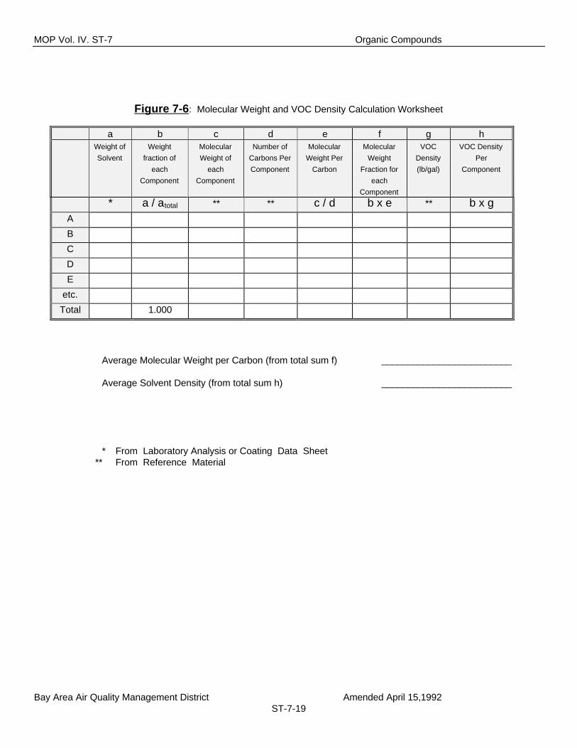
9.5 Molecular weight and VOC Density Calculations. If organic mass rateemissions are subject to rules requiring the determination of precusororganic compounds or volatile organic compounds, then the averagemolecular weight of VOC per carbon (X VOC)must be determined. If it isnot practicable to determine or estimate X VOC, then a value of 14 lb/lb-mol shall be used. Calculations of exhaust emission rates shall be basedupon the same XVOC as that determined for the inlet. Use the worksheetshown in Figure 7-6 to correctly calculate or estimate the averagemolecular weight.
9.6 Mass flow rate of carbon monoxide is calculated according to equation 6:
28(lb CO/lb-mole) x Qo x CCO x 60 (min/hr)MCO = ______________________________________ (6)
386.9 (SDCF/lb-mole) x 106(ppm)
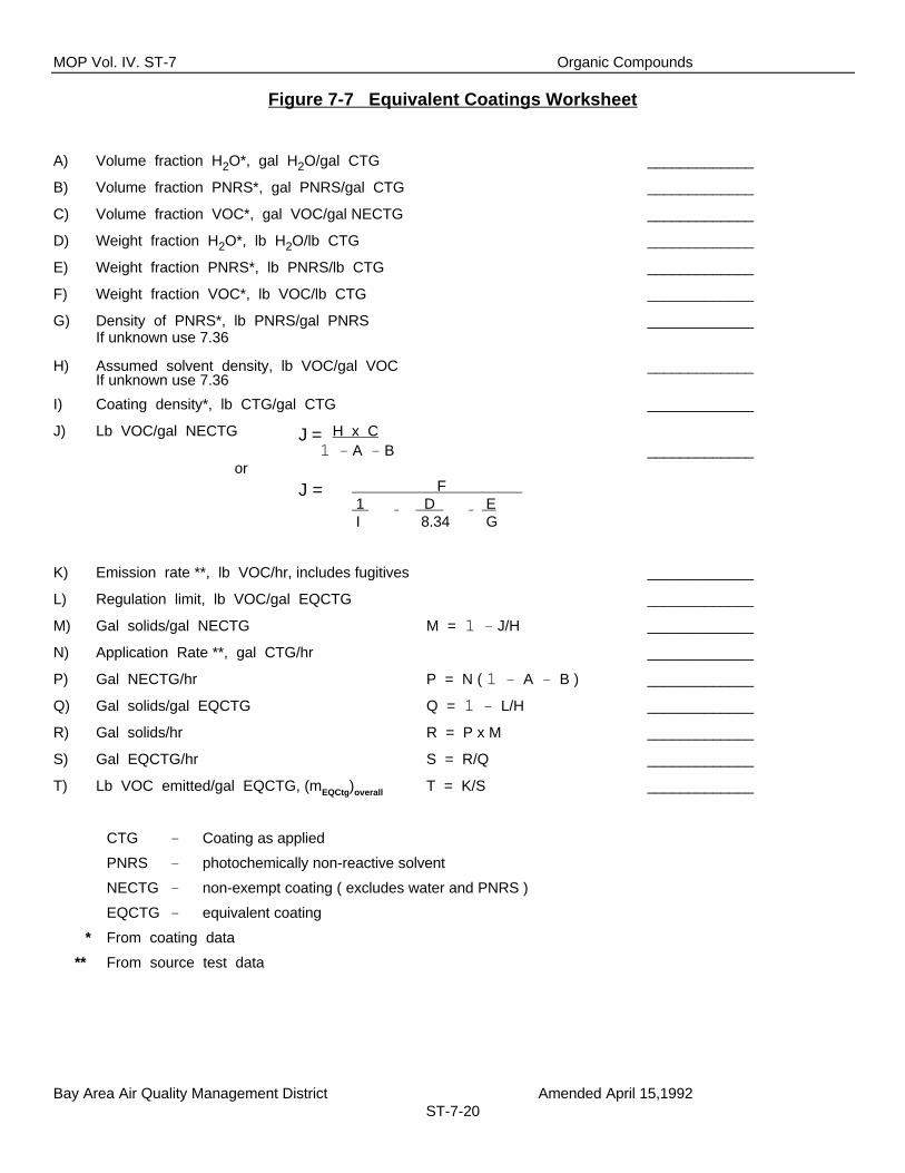
9.7 The VOC Emission Factor, (m Ctg)overall, from coating operations, will becalculated according to equation 7. If organic emissions are subject toequivalent control (for example: Regulation 8 Rule 11, Section 302), theEquivalent Coatings Emission Factor, (m EQCtg)overall, shall be calculatedusing worksheet shown in Figure 7-7. Fugitive emissions shall be added tomeasured emission rates by calculating solvent usage rate (lb/hr),subtracting control device inlet VOC rate and adding the result to the controldevice outlet VOC rate.
(MVOC)overall(mCtg)overall = _______________________ (7)
Application Rate (gal /hr)
9.8 If organic emissions are controlled by incineration, the efficiency of oxidationto carbon dioxide for the determination of exemption in Regulation 8, Rule 1,Section 110.3, shall be calculated using equations 8 or 9. Operationswhose emissions are not controlled by incineration or are not subject to theexemption, shall be calculated using equations 10 or 11.
9.8.1 If the control device is an incinerator and (M CO)out is greater than(MCO)in, then control efficiency will be calculated using equation 8 or9:

MOP Vol. IV. ST-7 Organic Compounds
Bay Area Air Quality Management District Amended April 15,1992ST-7-9
(MNMOC)in - (MNMOC)out - (12 /28) x {(MCO)out - (MCO)in}
Edevice = ______________________________________________________ x 100% (8)(MNMOC)in
(MVOC)in - (MVOC)out - (XVOC/28) x {(MCO)out - (MCO)in}
Edevice = _____________________________________________________ x 100% (9)(MVOC)in
9.8.2 In all other situations, the control efficiency will be calculated usingequation 10 or 11:
(MNMOC)in - (MNMOC)outEdevice = ____________________ x 100% (10)
(MNMOC)in
(MVOC)in - (MVOC)outEdevice = ___________________ x 100% (11)
(MVOC)in
9.9 Overall mass rate emissions shall include fugitive emissions according toequations 12 through 15.
9.9.1 Overall mass rate emissions of Non-Methane Organic Carbon shallinclude fugitive emissions as given by equations 12 and 13:
(MNMOC)fugitive = (MNMOC)process - (MNMOC)in (12)
(MNMOC)overall = (MNMOC)out + (MNMOC)fugitive (13)
9.9.2 Overall mass rate emissions of Volatile Organic Compounds shal linclude fugitive emissions as given by equations 14 and 15:
(MVOC)fugitive = (MVOC)process - (MVOC)in (14)
(MVOC)overall = (MVOC)out + (MVOC)fugitive (15)
9.10 Sample calculations.
Example 1: Incinerator Abating Cyclohexanone
Given:
Process data shows coating applied at a rate of 8 gallons per hour.Laboratory analysis of the coating indicates it contains 5 pounds VOC per

MOP Vol. IV. ST-7 Organic Compounds
Bay Area Air Quality Management District Amended April 15,1992ST-7-10
gallon. The VOC is pure Cyclohexanone (C 6H10O). The Incinerator outletflow is virtually the same as the inlet flow.
Inlet measurements to the Afterburner:
Qo = 1,000 SDCFM(CTC)comb = 22,400 ppm(CCO)comb < 10 ppm
(CTHC)comb < 5 ppmCCO = 250 ppmCM = 150 ppm
C CO2 = 10,000 ppm
Outlet measurements from the Afterburner:
CTHC = 200 ppmCM = 100 ppm
CCO = 50 ppm
Calculation of Afterburner Inlet parameters:
CTC = (CTC)Comb + (CCO)Comb + (CTHC)Comb (1)
= 22400 - (<10) - (<5)
CTC = 22400 ppm
CNMOC = CTC - CCO2 - CCO - CM (2)
= 22400 - 10000 - 250 - 150
CNMOC = 12000 ppm
12(lb C/lb-mole C1) x Qo x CNMOC x 60 (min/hr)MNMOC = ________________________________________ (4)
386.9 (SDCF/lb-mole) x 106(ppm)
= (12 x 1000 x 12000 x 60)/(386.9 x 10 6)
MNMOC = 22.3 lbs NMOC/hr
XVOC = 16.33 lb VOC/lb-mol C1 (From Worksheet IV-22)
XVOC x Qo x CNMOC x 60 (min/hr)MVOC = ______________________________ (5)
386.9 (SDCF/lb-mole) x 106(ppm)
= (16.33 x 1000 x 12000 x 60)/(386.9 x 10 6)

MOP Vol. IV. ST-7 Organic Compounds
Bay Area Air Quality Management District Amended April 15,1992ST-7-11
MVOC = 30.39 lb VOC/hr
Calculation of Afterburner Outlet parameters:
CNMOC = CTHC - CM (3)
= 200 - 100
CNMOC = 100 ppmv
12(lb C/lb-mole C1) x Qo x CNMOC x 60 (min/hr)MNMOC = __________________________________________ (4)
386.9 (SDCF/lb-mole) x 106(ppm)
= (12 x 1000 x 100 x 60)/(386.9 x 10 6)
MNMOC = 0.19 lb NMOC/hr
XVOC x Qo x CNMOC x 60 (min/hr)MVOC = _______________________________ (5)
386.9 (SDCF/lb-mole) x 106(ppm)
= (16.33 x 1000 x 100 x 60)/(386.9 x 10 6)
MVOC = .25 lb VOC/hr
Calculation of Afterburner and Process parameters:
(MVOC)in - (MVOC)outEdevice = _________________ x 100% (11)
(MVOC)in
= ((30.39 - .25)/30.39) x 100 %
Edevice = 99.1 %
(MNMOC)fugitive = (MNMOC)process - (MNMOC)in (12)
= (12/16.33) x 40 - 22.3
(MNMOC)fugitive = 7.09 lb NMOC/hr
(MNMOC)overall = (MNMOC)out + (MNMOC)fugitive (13)
= 0.19 + 7.09
(MNMOC)overall = 7.28 lb NMOC/hr
(MVOC)fugitive = (MVOC)process - (MVOC)in (14)
= 40 - 30.39

MOP Vol. IV. ST-7 Organic Compounds
Bay Area Air Quality Management District Amended April 15,1992ST-7-12
(MVOC)fugitive = 9.61 lb VOC/hr
(MVOC)overall = (MVOC)out + (MVOC)fugitive (15)
= .25 + 9.61
(MVOC)overall = 9.86 lb VOC/hr
(MVOC)overall(mCtg)overall = __________________________ (7)
Application Rate (gal/hr)
9.86= _________
8.0
= 1.23 lb VOC/gallon coating applied
Example 2:
Given:
A source subject to Regulation 8, Rule 2, uses incineration to control non-methane organic carbon emissions. The process operates 20 hours perday.
Inlet Measurements to the Afterburner:
Qo = 100 SDCFMCTC = 10300 ppmvCCO2
= 500 ppmvCCO = 800 ppmvCM < 5 ppmvOutlet Measurements from the Afterburner:
Qo = 500 SDCFMCTHC = 500 ppmvCCO = 400 ppmvCM = 100 ppmv
Calculation of Afterburner Inlet parameters:
CNMOC = CTC - CCO2 - CCO - CM (2)
= 10300 - 500 - 800 - (<5)
CNMOC = 9000 ppmv
12(lb C/lb-mole C1) x Qo x CNMOC x 60 (min/hr)MNMOC = ________________________________________ (4)
386.9 (SDCF/lb-mole) x 106 (ppm)

MOP Vol. IV. ST-7 Organic Compounds
Bay Area Air Quality Management District Amended April 15,1992ST-7-13
= (12 x 100 x 9000 x 60)/386.9 x 10 6)
MNMOC = 1.675 lb NMOC/hr
28(lb CO/lb-mole) x Qo x CCO x 60 (min/hr)MCO = ____________________________________ (6)
386.9 (SDCF/lb-mole) x 106 (ppm)
= (28 x 100 x 800 x 60)/(386.9 x 10 6)
MCO = 0.347 lb CO/hr
Calculation of Afterburner Outlet parameters:
CNMOC = CTHC - CM (3)
= 500 - 100
CNMOC = 400 ppmv
12(lb C/lb-mole C1) x Qo x CNMOC x 60 (min/hr)MNMOC = _______________________________________ (4)
386.9 (SDCF/lb-mole) x 106 (ppm)
= (12 x 500 x 400 x 60)/386.9 x 10 6)
MNMOC = 0.372 lb NMOC/hr
28(lb CO/lb-mole) x Qo x CCO x 60 (min/hr)MCO = _______________________________________ (6)
386.9 (SDCF/lb-mole) x 106 (ppm)
= (28 x 500 x 400 x 60)/(386.9 x 10 6)
MCO = 0.868 lb CO/hr
Calculation of Afterburner Efficiency:
(MNMOC)in - (MNMOC)out - (12/28 ) x {(MCO)out - (MCO)in}
Edevice = _________________________________________________________ x 100% (8)(MNMOC)in
(1.675 - 0.372 - (12/28) x {(0.868 - 0.347))= ___________________________________ x 100%
1.675
Edevice = 64.5 %
Emission Rate (lb/day) = Emission Rate (lb/hr) x Operating Time (hr/day)

MOP Vol. IV. ST-7 Organic Compounds
Bay Area Air Quality Management District Amended April 15,1992ST-7-14
= 0.372 lb NMOC / hr x 20 hr / day
= 7.44 lb NMOC/day
Example 3: Paint spray booth abated by a Charcoal Adsorber
Given:
Solvent fumes to the adsorber are primarily from methyl ethyl ketone(MEK). Material and Safety Data Sheets (MSDS) indicate that othersolvents are also present, but plant operating data show their contributionis unknown and less than 10 % of the total. The coating is 5.2 lb VOC/galand 3.0 lb solids/gal. Regulations do not allow the use of a coating with asolvent content in excess of 3.5 lb VOC/gal unless emissions arecontrolled to an extent equivalent to that of a compliant coating. There isno water in the coating. No dilution of gas occurs through the adsorberbed.
Estimate:
XVOC = 18 lb/lb-mol (ref. sect 9.5 and Fig. 7-6)
Process Measurements:
Paint is drawn out of a one foot diameter drum at a rate of 3.0 inches perhour. 100 pieces per hour at 400 in 2 per piece are coated with paint.Quality assurance data indicate that there are 0.20 grams of solids per 4in2.
Inlet Measurements:
Qo = 1000 SDCFMCTC = 2350 ppmCCO < 10 ppmCCO2 = 350 ppmCM < 5 ppm
Outlet Measurements:
CTHC = 40 ppmCM < 5 ppm
Calculation of process parameters:
One way to calculate the volume of paint used is:Paint Used = 3/12 ft/hr x π (1 ft2)/4 x 7.48 gal/ft3Paint Used = 1.469 gph

MOP Vol. IV. ST-7 Organic Compounds
Bay Area Air Quality Management District Amended April 15,1992ST-7-15
An alternative way to calculate paint usage would be:
Paint Used = (0.2 g solids/4 in 2)x(lb/453.6 g)x(100 pieces/hr)x(400in2/piece)x(gal/3 lb solids)Paint Used = 1.469 gph
(MVOC)process = 1.469 gph x 5.2 lb VOC/gal(MVOC)process = 7.638 lb VOC/hr
Calculation of Adsorber Inlet parameters:
CNMOC = 2000 ppmv
XVOC x Qo x CNMOC x 60 (min/hr)MVOC = ______________________________ (5)
386.9 (SDCF/lb-mole) x 106 (ppm)
= (18 x 1000 x 2000 x 60)/(386.9 x 10 6)
MVOC = 5.582 lb VOC/hr
Calculation of Adsorber Outlet parameters:
CNMOC = CTHC - CM (3)
CNMOC = 40 ppmv
XVOC x Qo x CNMOC x 60 (min/hr)MVOC = _______________________________ (5)
386.9 (SDCF/lb-mole) x 106 (ppm)
= (18 x 1000 x 40 x 60)/(386.9 x 10 6)
MVOC = .112 lb VOC/hr
(MVOC)fugitive = (MVOC)process - (MVOC)in (16)
= 7.638 - 5.582
(MVOC)fugitive = 1.056
Calculation of Adsorber Bed parameters:
(MVOC)in - (MVOC)outEdevice = ____________________ x 100% (11)
(MVOC)in
= (5.582 - 0.112)/5.582 x 100 %
Edevice = 98.0 %

MOP Vol. IV. ST-7 Organic Compounds
Bay Area Air Quality Management District Amended April 15,1992ST-7-16
Calculation of Emissions per gallon equivalent coating: (ref. Fig. 7-7)
Line A = 0 There is no water in this coatingLine B = 0 There are no exempt volatiles in this coatingLine C Leave blank. This is not listed on the MSDS cited in
this exampleLine D = 0 No waterLine E = 0 No exempt volatilesLine F = 0.671 5.2 lb VOC per 8.2 lb CoatingLine G = 7.36 There is no PNRS, therefore assign it this default
valueLine H = 6.885 MEK has a known densityLine I = 8.2 Specified operating conditionLine J = 5.2 F/(1/I - D/8.34 - E/G)Line K = 1.168 Exhaust of .112 plus fugitive of 1.056 From source
test data and calculationsLine L = 3.5 Specified in this example. Actual value will depend
on which regulation appliesLine M = 0.245 1 - J/HLine N = 1.469 Calculated aboveLine P = 1.469 (1 - A - B) × NLine Q = 0.492 1 - L/HLine R = 0.359 P x MLine S = 0.731 R/QLine T = 1.60 K/S
(mEQCtg)overall = 1.60 lb VOC/gal Equivalent Coating
Example 4 Petroleum Dry Cleaner
Given:
Petroleum Dry Cleaner washes two 10 lb loads per hour. The solventused has an average molecular weight per carbon of 14. Gases arevented to a solvent recovery dryer.
Outlet Measurements:
Qo = 1000 SDCFMCTHC = 100 ppmCM < 5 ppm
Calculation of Recovery Dryer Exhaust:
XVOC x Qo x CNMOC x 60 (min/hr)MVOC = ______________________________ (5)
386.9 (SDCF/lb-mole) x 106 (ppm)
= (14 x 1000 x 100 x 60)/(386.9 x 10 6)

MOP Vol. IV. ST-7 Organic Compounds
Bay Area Air Quality Management District Amended April 15,1992ST-7-17
MVOC = 0.217 lb VOC/hr
MVOC /100 kg clothes = MVOC/(2 load/hr x 10 lb/load) x (5/5) x ( Kg/lb/Kg/lb)
= 5 x MVOC (Kg/lb)(hr) 100 Kg Clothes
MVOC /100 kg clothes = 1.085 kg VOC/100 kg clothes
10. Reporting
10.1 Results shall be reported as shown in Figure 7-8 .
11. Nomenclature
CCO [=] Concentration of Carbon Monoxide, ppmv
CCO2 [=] Concentration of Carbon Dioxide, ppmv
CM [=] Concentration of Methane, ppmv
CNMOC [=] Concentration of Non-Methane Organic Carbon, ppmv
CTC [=] Concentration of Total Carbon, ppmv
CTHC [=] Concentration of Total Hydorcarbons, ppmv
Edevice [=] Efficiency with which NMOC or VOC emissions areabated by the Control Device on a mass basis, %
MCO [=] Mass flow rate of CO, lbs/hr
MNMOC [=] Mass flow rate of NMOC, lbs/hr
MVOC [=] Mass flow rate of VOC, lbs/hr
Qo [=] Volumetric Flowrate, SDCFM
XVOC [=] Molecular weight of VOC per Carbon, lb VOC/lb-molC1
(CCO)comb [=] Apparent CO concentration measured at combustor.Non-zero only when combustor is less than 100%efficient, ppmv
(CTC)comb [=] Apparent CO2 (Total Carbon) measured at combustor.(CTC)Comb is less than CTC only when combustor isless than 100% efficient, ppmv
(CTHC)comb [=] Apparent THC measured at combustor. Non-zeroonly when combustor is less than 100% efficient,ppmv

MOP Vol. IV. ST-7 Organic Compounds
Bay Area Air Quality Management District Amended April 15,1992ST-7-18
(mCtg)overall [=] Mass flow rate of VOC, including fugitives, exhaustedfrom a coating operation relative to the quantity ofcoating applied, lb/gal
(mEQCtg)overall [=] Mass flow rate of VOC, including fugitives, exhaustedfrom a coating operation relative the quantity ofequivalent coating used had a compliant coating beenused in place of the actual coating, lb/gal
(MCO)in [=] Mass flow rate of CO at the inlet of a given abatementdevice, lb/hr
(MCO)out [=] Mass flow rate of CO at the outlet of a givenabatement device, lb/hr
(MNMOC)fugitives [=] Mass flow rate of NMOC attributed to fugitiveemissions from a given process, lb NMOC/hr
(MNMOC)in [=] Mass flow rate of NMOC at the inlet of a givenabatement device, lb NMOC/hr
(MNMOC)out [=] Mass flow rate of NMOC at the outlet of a givenabatement device, lb NMOC/hr
(MNMOC)overall [=] Mass flow rate of NMOC attributed to fugitive andexhausted emissions from abatement devicesassociated with a given process, lb NMOC/hr
(MNMOC)process [=] The calculated usage rate of NMOC based on processdata, lb NMOC/hr
(MVOC)fugitives [=] Mass flow rate of organics as VOC attributed tofugitive emissions, lb VOC/hr
(MVOC)in [=] Mass flow rate of organics as VOC at the inlet of agiven abatement device, lb VOC/hr
(MVOC)out [=] Mass flow rate of organics as VOC at the exhaust of agiven abatement device, lb VOC/hr
(MVOC)overall [=] Mass flow rate of organics as VOC attributed tofugitive and exhausted emissions from abatementdevices associated with a given process, lb VOC/hr
(MVOC)process [=] The calculated usage rate of organic compoundsbased on process data, lb VOC/hr
MOP Vol. IV. ST-7 Organic Compounds
Bay Area Air Quality Management District Amended April 15,1992ST-7-19
Figure 7-6: Molecular Weight and VOC Density Calculation Worksheet
a b c d e f g hWeight ofSolvent
Weightfraction of
eachComponent
MolecularWeight of
eachComponent
Number ofCarbons PerComponent
MolecularWeight Per
Carbon
MolecularWeight
Fraction foreach
Component
VOCDensity(lb/gal)
VOC DensityPer
Component
* a / atotal ** ** c / d b x e ** b x gA
B
C
D
E
etc.
Total 1.000
Average Molecular Weight per Carbon (from total sum f) _________________________
Average Solvent Density (from total sum h) _________________________
* From Laboratory Analysis or Coating Data Sheet** From Reference Material
MOP Vol. IV. ST-7 Organic Compounds
Bay Area Air Quality Management District Amended April 15,1992ST-7-20
Figure 7-7 Equivalent Coatings Worksheet
A) Volume fraction H2O*, gal H2O/gal CTG _____________
B) Volume fraction PNRS*, gal PNRS/gal CTG _____________
C) Volume fraction VOC*, gal VOC/gal NECTG _____________
D) Weight fraction H2O*, lb H2O/lb CTG _____________
E) Weight fraction PNRS*, lb PNRS/lb CTG _____________
F) Weight fraction VOC*, lb VOC/lb CTG _____________
G) Density of PNRS*, lb PNRS/gal PNRS _____________If unknown use 7.36
H) Assumed solvent density, lb VOC/gal VOC _____________If unknown use 7.36
I) Coating density*, lb CTG/gal CTG _____________
J) Lb VOC/gal NECTG J = H x C1 - A - B _____________
or
J = F 1 D E I 8.34 G
K) Emission rate **, lb VOC/hr, includes fugitives _____________
L) Regulation limit, lb VOC/gal EQCTG _____________
M) Gal solids/gal NECTG M = 1 - J/H _____________
N) Application Rate **, gal CTG/hr _____________
P) Gal NECTG/hr P = N ( 1 - A - B ) _____________
Q) Gal solids/gal EQCTG Q = 1 - L/H _____________
R) Gal solids/hr R = P x M _____________
S) Gal EQCTG/hr S = R/Q _____________
T) Lb VOC emitted/gal EQCTG, (mEQCtg)overall T = K/S _____________
CTG - Coating as applied
PNRS - photochemically non-reactive solvent
NECTG - non-exempt coating ( excludes water and PNRS )
EQCTG - equivalent coating
* From coating data
** From source test data

MOP Vol. IV. ST-7 Organic Compounds
Bay Area Air Quality Management District Amended April 15,1992ST-7-21
Figure 7-8
Report No.:
Test Date:
BAY AREAAIR QUALITY MANAGEMENT DISTRICT
Summary ofSource Test Results
Test Times:
Run A:
Run B:
Run C:
Source Information Test RepresentativesFirm Name and Address Firm Representative and Title
Phone No. ( )
Permit Conditions: Source: Operating Parameters
Plant No. Permit No.Operates Hr/Day & Day/Yr.
Applicable Regulations:
Source Test Results and Comments:RUN A RUN B RUN C AVERAGE
METHOD: TEST IN* OUT* IN OUT IN OUT IN OUT
Run Time,minutesSample point temperature, F
ST-17 Stack Volume Flowrate,SDCFMST-14 O2 , percentST-5 CO2, percentST-6 CO, PPMST-23 H2O, percentST-7 Non-methane organic carbon, as C1
a) PPMb) lb/hr
ST-7 Volatile Organic Compounds, as C1
a) PPMb) lb/hr
ST-7 Abatement Efficiency, %
* Control device inlet** Control device outlet
Test Team Leader Date Reviewed by Date Approved By Date