Sortal Structures: Supporting … Structures: Supporting RepresentationalFlexibility for Building...
20
Carnegie Mellon University Research Showcase @ CMU School of Architecture College of Fine Arts 2007 Sortal Structures: Supporting RepresentationalFlexibility for Building Domain Processes Rudi Stouffs Carnegie Mellon University Ramesh Krishnamurti Carnegie Mellon University Follow this and additional works at: hp://repository.cmu.edu/architecture Part of the Architecture Commons is Article is brought to you for free and open access by the College of Fine Arts at Research Showcase @ CMU. It has been accepted for inclusion in School of Architecture by an authorized administrator of Research Showcase @ CMU. For more information, please contact research- [email protected].
Transcript of Sortal Structures: Supporting … Structures: Supporting RepresentationalFlexibility for Building...

Carnegie Mellon UniversityResearch Showcase @ CMU
School of Architecture College of Fine Arts
2007
Sortal Structures: SupportingRepresentationalFlexibility for Building DomainProcessesRudi StouffsCarnegie Mellon University
Ramesh KrishnamurtiCarnegie Mellon University
Follow this and additional works at: http://repository.cmu.edu/architecture
Part of the Architecture Commons
This Article is brought to you for free and open access by the College of Fine Arts at Research Showcase @ CMU. It has been accepted for inclusion inSchool of Architecture by an authorized administrator of Research Showcase @ CMU. For more information, please contact [email protected].
Computer-Aided Civil and Infrastructure Engineering 22 (2007) 98–116
Sortal Structures: Supporting RepresentationalFlexibility for Building Domain Processes
Rudi Stouffs∗
Faculty of Architecture, Delft University of Technology, PO Box 5043, 2600 GA Delft, The Netherlands
&
Ramesh Krishnamurti & Kuhn Park
School of Architecture, Carnegie Mellon University, Pittsburgh, PA
Abstract: We present a formal approach to represen-tational flexibility, sorts, to support alternative represen-tations of an entity. The approach is constructive, basedon a part relation on elements within a sort, which en-ables the recognition of emergent information. The useof data functions as a sort provides for the embedding ofdata queries within a representational structure. We dis-cuss the application of sorts to supporting alternative dataviews, illustrating this through a case study in buildingconstruction.
1 INTRODUCTION
In the building domain, there is always a need for multi-ple representations of the same entity. A building may beconsidered in its entirety, as a shape, a collection of partsor some grouping of properties. The building domainis multi-disciplinary, involving participants, knowledgeand information from various specializations; problemsrequire a multiplicity of views, each distinguished by par-ticular interests and emphases. In this article, we considerthe representation of such views.
Problems in the building domain are mainly data-driven. Important issues that arise in solving buildingdomain questions stem from knowing what kind of data
∗To whom correspondence should be addressed. E-mail: [email protected].
exists, how effectively can the data be queried and moreover, as data is shared across different problem solvers,how effectively can the data be structured to suit a spe-cific need. We have been working on a formal approach,named sorts, to deal with these issues, one that looksat data as opposed to knowledge as the driving force inrepresentations
2 MULTIPLE REPRESENTATIONSIN THE BUILDING DOMAIN
The architect is typically concerned with configurationaland aesthetic aspects of a design, the structural engi-neer considers structural members and their relation-ships, and the performance engineer is interested inthermal, lighting, or acoustical performance. Each actortakes their own professionally oriented view—derivedfrom an understanding of current problem solution tech-niques in their respective domain—that requires a dif-ferent representation of the same (abstract) entity. Eachview specifies a particular selection of information, pre-sented in a particular way. As such, different views—or different representations—may derive from differentdesign stages, and may also support different persons orapplications within the same design stage. Even withinthe same task, or by the same person, various repre-sentations may serve different purposes defined within
C© 2007 Computer-Aided Civil and Infrastructure Engineering. Published by Blackwell Publishing, 350 Main Street, Malden, MA 02148, USA,
and 9600 Garsington Road, Oxford OX4 2DQ, UK.

Sortal structures 99
the problem context and selected approach. This is cer-tainly true in architecture, where the design process,by its exploratory and dynamic nature, invites a vari-ety of approaches and representations (see, for example,Kolarevic, 2000).
There has been concerted effort in developing inte-grated product models that span multiple disciplines,multiple methodologies and support different views(e.g., Kiviniemi, 2006). These models enable informationexchange between representations and collaborationacross disciplines; examples include the ISO STEP stan-dard for the definition of product models (ISO, 1994),and the Industry Foundation Classes (IFCs) of the Inter-national Alliance for Interoperability (IAI), an object-oriented data model for product information sharing(Liebich, 2006). These efforts characterize an a prioritop-down approach: an attempt is made at establishingan agreement on concepts and relationships, which offera complete and uniform description of the project data,mainly independent of any project specifics (Stouffs andKrishnamurti, 2001). We consider here how data can beeffectively structured a posteriori.
2.1 Design representation and creativity
In general, integrated product models do not support thecreative aspects of building design, especially, in earlydesign phases. This is because design creativity often re-lies on restructuring information as yet not captured ina current information structure—that is, emergent infor-mation, as, for example, when the design provides newinsights that lead to a new interpretation of the con-stituent design entities. To some extent, creativity canbe supported by descriptions of design entities, whichhave “known” parts. When a design description is con-sidered to have indefinite parts, new design entities be-come recognized as alternative collections of these parts,and the description can be reinterpreted as composed ofdifferent new “known” design entities. These descrip-tions can be augmented with properties that have defi-nite descriptions, again, with definite or indefinite parts.Classic representation schemes deal with definite de-scriptions, generally with definite parts, and propertiesare certainly expressed as definite descriptions with defi-nite parts. The classic product modeling approaches em-ployed in CAD require specification of design entitiesas objects (with properties) that are maintained at alltimes, unless explicitly altered. Any reinterpretation ofdesign entities requires a specification of change—forour purpose, computational change—that not only fixesthe source and destination object types beforehand, butalso fixes the numbers and mapping between proper-ties. Previously, we have shown that continuity of suchcomputational changes, from the standpoint of design ra-
tionale, requires anticipation of the particular structuresthat are to be changed (Krishnamurti and Stouffs, 1997).Creativity, on the other hand, goes beyond such anticipa-tion. See Knight and Stiny (2001) for further elaborationson classical versus nonclassical computation in design.
2.2 Emergent information and rules
Recognizing emergent information structures requiresdetermining a transformation under which a specifiedstructure is similar to a part of the original (Krishnamurtiand Earl, 1992). There are two prime requirements toconsider.
Firstly, we need a specification of allowable transfor-mations. Which kinds of transformations are permitteddepend on the kind of information being recognized.For example, in spatial recognition, the transformationsare, commonly, Euclidean: a square must be computa-tionally recognized as a square, irrespective of scale, ori-entation or location. Likewise, transformations can beconsidered for other kinds of information—for example,search-and-replace in text editing allow for case trans-formations of the constituent letters.
Secondly, we need a definition for the part relationshipthat governs when an information structure is considereda part of another. Formally, this part relationship may befreely defined so long as it constitutes a partial order.For shapes this part relation defines an algebra—that is,a shape is specified as an element of the algebra, orderedby a part relation, closed under operations of sum, dif-ference and product, and affine transformations (Stiny,1991; Stouffs, 1994). Moreover, under the part relation,any part of a shape is a shape. As a shape specifies anindefinite number of (sub-) shapes, each a part of theoriginal, it follows that we can deal with shape indeter-minately, and in this way, new shapes emerge.
Geometrically, the maximal element representation(Krishnamurti, 1992; Stouffs, 1994) captures this no-tion precisely. Consider the combination of two squaresshown in Figure 1. Each square defines an object madeup of four line segments. Visually, however, the compo-sition contains not two, but three squares. To recognizethis third square, each square “object” needs to be rein-terpreted as a collection of six line segments, such thattwo can be taken from each to define the middle squareobject. However, the transformation of a square objectinto such a collection of six line segments is specific tothis particular context, and not generally pertinent. Un-der the maximal element representation, each object is,in a minimal way, made up of maximal line segments,and each such maximal line segment specifies an indef-inite number of (sub-) segments that are each part ofthe original segment. Thus, the four line segments defin-ing the middle square object can always be found in the

100 Stouffs, Krishnamurti & Park
Fig. 1. A composition of two or three squares.
representation of the original two squares, each a col-lection of four maximal line segments. Furthermore, al-though an indefinite number of other collections of linesegments can be determined and represented, none is ofany higher importance, except by designer choice. Thisprovides the designer with the freedom to reinterpret adesign in any way, and to have this interpretation sup-ported by the system.
Recognizing emergent information is useful, espe-cially, when the emergent information is subsequentlythe subject of an operation or manipulation, as in situa-tions that rely on a restructuring of emergent informa-tion. Data recognition and subsequent manipulation canbe considered part of a single computation s – f (a) +f (b), where s is a data collection, a is a representa-tion of the data pattern, f is a transformation underwhich a is a part of s, and f (b) is the data replacingf (a) in s. In Krishnamurti and Stouffs (1997) we discusss – f (a) + f (b) as a computational expression of spatialchange, derived from a design rule: a → b. Rule applica-tion, then, consists of replacing the emergent data cor-responding to a, under some allowable transformation,by b, under the same transformation.
Formally and technically, rules can be grouped as adevice for specifying a language, namely, the set of alldesigns generated. Each design in the language is gen-erated from an initial design, and employs the rules toarrive at the design. In spatial design, the specification ofrules leads naturally to the generation and exploration ofpossible spatial designs. Both Mitchell (1993) and Stiny(1993, 1994) as well as more recently in the special issue
on design spaces (Stouffs, 2006), some authors have re-marked on the importance of emergent spatial elementsand/or rules in design search.
The concept of search is much more fundamental thanany generational form alone might imply. Any muta-tion of a data collection into another, or parts of oth-ers, constitutes an action of search. As such, a rule maybe considered to specify a particular composition of op-erations and/or transformations that is recognized as anew, single, operation and applied as such. Individually,rules serve to facilitate common operations, for exam-ple, for the changing of one data collection into anotheror for the creation of new design information based onexisting information in combination with a rule. Collec-tively, rules act as generators for the creation of cer-tain sets of designs and for the derivation of certaininformation.
3 SORTS
The algebraic model for shapes and the maximal ele-ment representation have their origin in shape grammarresearch (Stiny, 2006). These were initially developedfor shapes, made up of points and line segments, andlater extended to planar and volume segments (Stouffs,1994). Each spatial element type specifies its own alge-bra. We employ the notation, Uij, to refer to the algebraof shapes made up of i-dimensional linear elements ina j-dimensional Euclidean space, and use Ui, as short-hand, whenever the dimensionality of the space is known(Stiny, 1991). Algebraically, a shape made up of morethan one type of spatial element, belongs to the Cartesianproduct algebra of its constituent spatial element types,for example, a shape comprising points and line segmentsbelongs to U0 × U1. The algebraic model can also ap-ply to shapes augmented with nongeometric properties,for example, labels, weights (e.g., line thickness; Stiny,1992), and colors (Knight, 1989)—likewise, Vi refers toshapes in Ui augmented with labels, and Wi to shapesaugmented with weights (Stiny, 1991).
We have extended this algebraic model to the for-malism, named sorts, initially presented in Stouffs andKrishnamurti (2002), and one that we are still revising.Briefly, a sort is a basic entity, conceptually, specifyinga set of similar data elements, for example, a class ofobjects, equivalently, a set of tuples solving a system ofequations. For example, points and lines are sorts, as aretriangles and squares. Each sort defines its own algebra:a sort of points corresponds to U0, a sort of line segmentsto U1, a sort of plane segments to U2 and a sort of vol-ume segments to U3. Sorts are not limited to geometricalobjects; colors are sortal, as are other data types. Sortssubsume conventional class representations.

Sortal structures 101
We define a conjunctive attribute operation on sorts.For example, we can define a sort of labeled points,(≈V0), from a sort of points and a sort of labels. Like-wise, we can define a sort of weighted line segments,(≈W1), or a sort of linear shapes (≈U0 × U1 × U2 ×U3). Sortal conjunction has similarity to the Cartesianproduct of algebras. Two observations can be made inthis respect.
Firstly, conjunction is not commutative: a sort of la-beled points is not identical to the sort of “pointed” la-bels. The former sort comprises points with associatedlabels, the latter, labels with associated points. This dis-tinction derives from the fact that each sort defines itsown algebraic operations, based on its own part relation-ship, and the resulting algebraic operations for the twoconjunctive sorts may behave differently (see below).Note that a table of unsorted coordinates and labels canbe sorted either as labeled points or pointed labels, andthe two sorts are distinct.
Secondly, an element belonging to a conjunctive sortnecessarily contains elements from its constituent sorts.For example, a shape belonging to a Cartesian productof algebras, for example, U0 × U1 × U2 × U3, must con-tain (spatial) elements from each algebra, otherwise itnecessarily belongs to the algebra specified by the actualCartesian product of the algebras of its specific elementtypes.
To define a sort—where neither the ordering of com-ponent sorts is important, nor the presence of ele-ments from the different component sorts is necessarilyexplicit—we define a disjunctive operation on sorts. Un-der this disjunction, any element of the resulting sortis necessarily an element of a constituent sort. Sortaldisjunction consequently defines a subsumption rela-tionship on sorts: a disjunctive sort subsumes each con-stituent sort, because each element of a constituent sortis also an element of the disjunctive sort.
Subsumption is a powerful mechanism for comparingalternative representations of the same entity. When arepresentation subsumes another, the entities of the for-mer represent those of the latter, without data loss. Thereare a number of representational formalisms that spec-ify a subsumption relationship, to achieve a partially or-dered type structure. Most are based on first-order logic.A good example in the building design domain is Wood-bury et al. (1999), who model design spaces by typedfeature structures, which represent data types throughrecord-like data structures. These structures facilitate theencapsulation of property information as (a variation of)attribute/value pairs (Aıt-Kaci, 1984). Moreover, prop-erties themselves may be typed by type structures, thatis, expressed in terms of record-like data structures, con-taining (sub-) properties. In this way, a subsumption re-lationship defines a partial ordering on type structures.
Furthermore, the algebraic operations of intersectionand union (or others similar) may be defined on typestructures so that the intersection of two type structuresis subsumed by either type structure, and the union oftwo type structures subsumes either type structure.
Sorts are likewise conceived, with, at least, one ex-ception: the association of properties to a sort occursthrough sortal conjunction—that is, each property of asort is itself a sort. Primitive sorts are the exceptions tothis rule. Like primitive data types, primitive sorts are thesmallest building blocks for building sortal representa-tional structures. Primitive sorts combine to form com-posite sorts under compositional operators over sorts.A primitive sort defines the domain of possible values,for example, a primitive sort of weights specifies the do-main of positive real numbers, and a primitive sort ofline segments specifies the domain of intervals on lin-ear carriers. Primitive sorts may be constrained over theextent of their domain, for example, limiting weights tovalues between 0 and 1. The subsumption relationshipbetween sorts then derives from the disjunction on sorts(similar to a union of two or more type structures) andan expression of constraints on primitive sorts. Spec-ifying an intersection-like operation on sorts adds nofurther value, as the intersection of two sorts can al-ways be reduced, through distributive and associativerules, to the intersection of primitive sorts (Stouffs andKrishnamurti, 2002). The intersection is nonempty onlywhen the primitive sorts are identical, except for possibleconstraints.
The subsumption relation specifies a hierarchy; more-over, it can be considered in terms of information speci-ficity. However, there is a distinction to be drawn inthe way in which subsumption is treated in sorts and infirst-order logic based representational formalisms asexemplified by type feature structures. First-order logicformalisms generally consider a relation of inclusion(hyponymy relation), commonly denoted as an is-a re-lationship. Sorts, on the other hand, consider a part-ofrelationship (meronymy relation).
Two simple examples illustrate this distinction. Con-sider a disjunction of a sort of points and a sort of line seg-ments; this allows for the representation of both pointsand line segments. We can say that the sort of pointsforms part of the sort of points and line segments—notethe part-of relationship. In first-order logic, this corre-sponds to the union of points and line segments. We cansay that both are bounded geometrical elements of zeroor one dimensions—note the is-a relationship.
This distinction becomes even more important whenwe consider an extension of sortal subsumption toconjunction. Consider a sort of labeled points as a con-junction of the sorts of points and labels. If we relax therequirement that an element belonging to a conjunctive

102 Stouffs, Krishnamurti & Park
sort necessarily contains elements from its constituentsorts, we can consider the sort of points to be part ofthe sort of labeled points, that is, a point is a labeledpoint without an associated label or, preferably, a pointis part of a labeled point. Thus, the sort of labeledpoints subsumes the sort of points. In logic formalisms,a relational construct is used to represent such associ-ations. For example, in Baader et al. (2003), roles aredefined as binary relationships between concepts. Con-sider a concept Point and a concept Label; the conceptof labeled points can then be represented as Point ∩ ∃has-Attribute.Label, denoting those points that have anattribute that is a label. Here, ∩ denotes intersection and∃R.C denotes full existential quantification with respectto role R and concept C. It follows then that Point ∩ ∃ hasAttribute. Label ⊆ Point; that is, the concept of pointssubsumes the concept of labeled points—this is quite thereverse of how it is considered in sorts.
Another important distinction is that first order logic-based representations generally make for an open worldassumption—that is, nothing is excluded unless it is doneso explicitly. For example, polygon objects may have anassigned color. When looking for a yellow square, logi-cally, every square is considered a potential solution—unless, it has an explicitly specified color, or it is other-wise known not to have the yellow color. The fact thata color is not specified does not exclude an object frompotentially being yellow. Sorts, on the other hand, holdto a closed world assumption. That is, we work with justthe data we have. A polygon has a color only if one isexplicitly assigned: when looking for a yellow square,any square will not do; it has to have the yellow colorassigned.
This restriction is used to constrain emergence. Morespecifically, labeled points commonly serve to con-strain the applicability of shape rules, which encap-sulate both shape recognition (emergence) and shapetransformation (computational change). Another wayof looking at this distinction between the open or closedworld assumptions is to consider their applicability toknowledge representation. To reiterate, logic-based rep-resentations essentially represent knowledge; sorts, onthe other hand, are intended to represent data—anyreasoning (computational change) is based purely onpresent (or emergent) data.
3.1 Behavioral specification
Sortal algebra implies the specification of a part relation-ship on the elements of a sort. The part relationship notonly governs when an element is a part of another, butalso how elements combine and intersect, and what theresult is of subtracting one element from another or froma collection of elements from the same sort.
The simplest specification of a part relationship corre-sponds to the subset relationship in mathematical sets.Such a part relationship applies to points and labels, forexample, a point is part of another point only if they areidentical, and a label is a part of a collection of labels onlyif it is identical to one of the labels in the collection. Here,sortal operations of addition (combining elements), sub-traction, and product (intersecting elements) correspondto set union, difference, and intersection, respectively.
Another kind of part relationship corresponds to in-terval behavior. Consider, for example, the specificationof a part relationship on line segments. A line segmentmay be considered as an interval on an infinite line (orcarrier); in general, one-dimensional quantities, such astime, can be treated as intervals. An interval is a part ofanother interval if it is embedded in the latter; intervalson the same carrier that are adjacent or overlap com-bine into a single interval. Specifically, a behavior forintervals can be expressed in terms of the behavior ofthe boundaries of intervals (Krishnamurti and Stouffs,2004). This behavior applies to indefinite intervals too,providing that there is an appropriate representation ofboth (infinite) ends of its carrier. Likewise, behaviorscan be specified for area intervals (plane segments) andvolume intervals (polyhedral segments). The notion ex-tends to intervals of higher dimensions.
Behaviors apply to composite sorts as well; that is, thepart relationship is defined on data elements belongingto a sort defined by conjunction (attribute) or disjunc-tion. Specifically, a composite sort inherits its behaviorfrom its component sorts depending upon the composi-tional relationship. For example, consider the followingsituation, common in CAD applications, of classifyingdata elements, say line segments, into layers. Here, wedefine the sort of labeled line segments as a compositionunder the attribute operator of a sort of line segmentsand a sort of layer labels. When layers are consideredas attribute values, it may seem intuitive to allow just asingle label for each line segment (most CAD applica-tions do not normally allow the same object to exist inmultiple layers at the same time). However, there is nocommon notion of a layer ordering (or a correspondingpart relationship) that can be used to define sortal op-erations on layer labels. Instead, were we to allow a setof layer labels to be assigned as an attribute to a linesegment, the result may be interpreted as a collectionof identical copies of the same line segment existing indifferent layers, and could be presented as such to theuser. To deal with or manipulate a single-layer copy, thatis, a copy of the line segment associated with a singlelabel (or singleton subset of labels), this copy needs tobe differentiated from the other copies of the same linesegment existing in the other layers. The sortal data ele-ment representing the single-layer line segment is a part
Sortal structures 103
of another sortal data element representing a multi-layerline segment if the first line segment is a part of the sec-ond (under the interval behavior for line segments) andif the single label of the first entity is a member of theset of labels for the second entity. Consequently, by sub-tracting the first entity from the second, the single-layerline segment is distinguished (i.e., selected) from the re-mainder. Thus, under the attribute operator, a data el-ement is part of a data collection if it is a part of thedata elements of the first component sort, and if it hasan attribute collection that is a part of the respective at-tribute collection(s) of the data element(s) of the firstcomponent sort it is a part of. When data collections ofthe same composite sort (under conjunction) are pair-wise summed (differenced or intersected), identical dataelements merge, and their attribute collections combine,under this operation. Elements with empty attributesare, necessarily, removed. Under conjunction, the com-posite behavior, in the first instance, is that of the firstcomponent sort.
The disjunctive operator distinguishes, instead, alloperand sorts such that each data element belongs ex-plicitly to one of these sorts. For example, a sort of pointsand lines distinguishes each data element as either apoint or a line. Consequently, a data element is part of adisjunctive data collection if it is a part of the partial datacollection of elements from the same component sort. Inother words, data collections from different componentsorts, under disjunction, never interact; the resulting datacollection is the set of collections from all componentsorts. When the operations of addition, subtraction orproduct are applied to two data collections of the samedisjunctive sort, each operation applies to the respectivecomponent collections.
Behaviors play an important role when assessing dataloss in data exchange between different sorts. When re-organizing the composition of the component sorts, un-der the attribute operator, the corresponding behaviormay be altered in such a way as to trigger data loss.Consider a behavior for weights (e.g., line thickness orsurface tones) as is apparent from drawings on paper—asingle line drawn multiple times, each time with a dif-ferent thickness, appears as if it were drawn once withthe largest thickness, even though it assumes the sameline with other thicknesses. When using numeric valuesto represent weights, the part relation on weights corre-sponds to the less-than-or-equal relation on numeric val-ues. Thus, weights combine into a single weight, with itsvalue as the least upper bound of the respective individ-ual weights, that is, their maximum value. Similarly, thecommon value (intersection) of a collection of weightsis the greatest lower bound of the individual weights,that is, their minimum value. The result of subtractingone weight from another is either a weight that equals
the numeric difference of their values or zero (i.e., noweight), and this depends on their relative values. Nowconsider a sort of weighted points, that is, a sort of pointswith attribute weights, and a sort of pointed weights,that is, a sort of weights with attribute points. A col-lection of weighted points defines a set of noncoincidentpoints, each having a single weight assigned (possiblythe maximum value of various weights assigned to thesame point). These weights may be different for differ-ent points. The behavior of the collection is, in the firstinstance, the behavior for points. On the other hand, acollection of pointed weights, which is defined as a sin-gle weight (which is the maximum of all weights con-sidered) with an attribute collection of points, adheres,in the first instance, to the behavior for weights. In bothcases, points are associated with weights. However, in thefirst case, different points may be associated with differ-ent weights, whereas, in the second case, all points areassociated with the same weight. In a conversion fromthe first to the second sort, data loss is inevitable. Anunderstanding of when and where exact translation ofdata between different sorts or representations is or isnot possible is important for assessing data integrity andcontrolling data flow (Stouffs et al., 1996).
Additionally, a behavioral specification is a prereq-uisite for the uniform handling of different and a pri-ori unknown data structures. Consider the associationof building performance data to design geometries. Thebehavior of these data, as a result of an alteration to thegeometry, can be expressed through a number of opera-tions chosen to match the expected behavior. When anapplication receives the data along with its behavioralspecification, the application can then correctly inter-pret, manipulate, and represent this information withoutunexpected data loss. Furthermore, the part relationshipthat underlies the behavioral specification for a sort en-ables the matching problem to be implemented for thissort. As composite sorts inherit their behavior and partrelationship from their component sorts, any technicaldifficulties in implementing matching apply just once,for each primitive sort.
3.2 Data functions
Computational design relies on effective informationmodels, not just for the creation of design artifacts, butalso for querying the characteristics of such artifacts.With respect to geometry, Mantyla (1988) remarkedthat these (geometric) representations must adequatelyanswer “arbitrary geometric questions algorithmically.”Even without the emphasis on geometric aspects,this remains as important today. However, currentcomputational design applications tend to focus on rep-resentations of design artifacts, and on the tools and

104 Stouffs, Krishnamurti & Park
operations for their creation and manipulation. Tech-niques for querying receive less attention and are oftenconstrained by the data representation system and meth-ods. Nevertheless, querying a design is as much an in-tricate aspect of the design process as is creation andmanipulation.
Querying design information, as distinguished fromvisual inspection, generally requires the analysis of ex-isting information to derive new information that is notexplicitly available in the information structure. A viablequery language has to be based on a model for repre-senting the different kinds of information that adhereto a consistent logic, providing access to information ina uniform and consistent manner, so that new queriescan be easily constructed and posed, based on intentinstead of availability. Sorts offer the flexibility to sup-port constructing alternative representations, to com-pare representations with respect to scope and coverage,as well as support the specification of operational behav-ior on data in a uniform way, based on a partial orderrelationship.
Data recognition, or pattern matching, plays an impor-tant role in the specification of design queries, as doescounting. Stouffs and Krishnamurti (1996) show how aquery language for querying graphical design informa-tion can be built from basic operations and geometricrelations which are defined as part of a maximal elementrepresentation for weighted geometries, augmented withoperations derived from techniques of counting and pat-tern matching. For example, by augmenting networksof lines that are represented as volume (or plane seg-ments) with labels as attributes, and by combining theseaugmented geometries under the operation of sum, asdefined for the representational model, colliding linesspecifically result in geometries that have more than onelabel as attribute. These collisions can easily be counted,whilst the labels, each associated with a geometry identi-fying colliding lines, and the geometry itself specifies thelocation of the collision.
To consider counting and other functional behavioras part of the representational approach, sorts considerdata functions as a kind of data, offering functional be-havior integrated into the data constructs. Data functionsare assigned to apply to one or more selected propertyattributes of selected sorts, each of which may, itself, bea data function. The resulting value of the data func-tion is then computed from the values of the respectiveproperty attributes of valid compositions of data enti-ties of these sorts. A composition of data entities is avalid composition if the data entities are encounteredalong the same path of object-attribute relationships,with some restrictions. Therefore, the target sorts mustbe related to the data function’s sorts within the repre-sentational structure under a sequence of one or more at-
tribute relationships. The resulting value is automaticallyrecomputed each time the data structure is traversed, forexample, when visualizing the structure. As data kind,data functions specify a functional description, a resultvalue, and one or more sorts and their respective prop-erty attributes.
Data functions can introduce specific behaviors andfunctionalities into representational structures, bothfor the purposes of counting and for other numericaloperations. Consider, for example, a data structure cor-responding to a composition of two sorts under the at-tribute operator where the attribute sort specifies a costper unit length to the other sort. By augmenting the datastructure with an inner product function, applied to thenumeric value attribute property of the cost sort and thelength attribute property of the other sort, the value ofthis function is then automatically computed as the sumof all cost values multiplied by the respective lengths ofthe other entities.
3.3 Implementation
For ease and brevity, we describe the implementation ofsorts in terms of UML classes (Rumbaugh et al., 2005).Some basic definitions are, however, needed. A sortal de-scription includes sorts, individuals and forms; a sort is aclass structure, specifying a single data type or a composi-tion of other class structures; an individual is a basic sor-tal element, that is, an instance of a class structure; and, aform is a collection of individuals of the same sort. Theseare the three main abstract classes in our Java implemen-tation. Figure 2 shows a conceptual UML model of theabstract Sort class and its five subclasses: PrimitiveSort,AttributeSort, DisjunctiveSort, Aspect and AspectsSort.A Sort has a context in which it is defined, a descriptionand an optional name. A PrimitiveSort specifies a singledata type; its individuals have a data value of the sametype. An AttributeSort is the composition of a simplesort (its base)—a primitive sort or an aspect—with an-other sort (its weight) under a conjunction. Its individu-als comprise an individual of the base sort (the associateindividual), which is assigned a form of the weight sortas its attribute (the attribute form). A DisjunctiveSort isa co-ordinate composition of two or more componentsorts—which can be a primitive sort, an attribute sort,or an aspect. A disjunctive sortal form (or metaform) isa composition of forms from the respective componentsorts. An AspectsSort is a sort of undirected relationshipsbetween two or more primitive sorts. Each undirectedrelationship is represented as two or more directed rela-tionship Aspects. AttributeSort and DisjunctiveSort canbe recursively defined. The actual implementation modelfor the corresponding package of classes is shown inFigure 3.

Sortal structures 105
Fig. 2. UML conceptual model of the abstract Sort class and its subclasses.
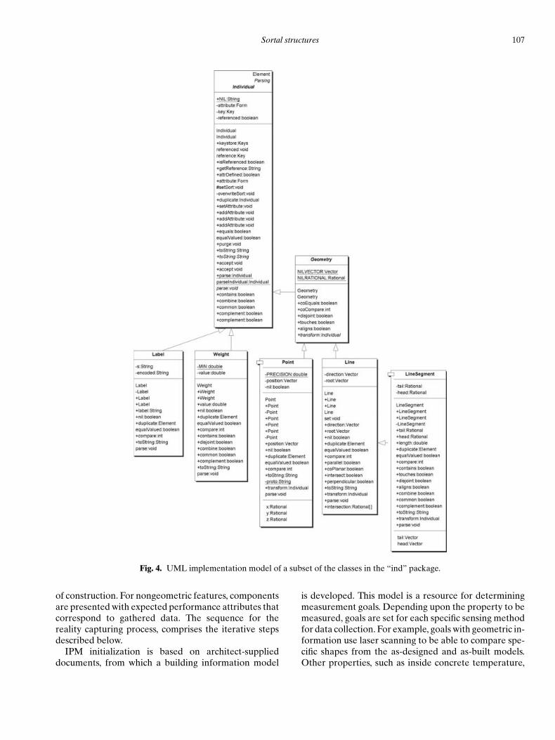
Each primitive sort is specified by a name, charac-teristic individual, and behavioral category. A charac-teristic individual is a subclass of the Individual classand specifies the representation of its data values andbehavioral methods. Figure 4 shows a UML implemen-tation model for the Individual class, with some of its sub-classes. The behavioral category is a subclass of the Formclass and specifies the operational behavior of the sortalforms; it is assigned in a categorization of the character-istic individuals. Figure 5 shows a UML implementationmodel for the “form” package of classes. The followingbehavioral categories have been implemented: discrete,interval, ordinal, and relational.
4 ASDMCON: SORTAL STRUCTURESIN BUILDING CONSTRUCTION
4.1 Background
The ASDMCon (Advanced Sensor-based Defect Man-agement at Construction sites) project involves col-laboration among researchers from three differentdisciplines at Carnegie Mellon University: Architec-ture, Robotics, and Civil and Environmental Engineer-ing (Yue et al., 2006). The premise underlying the projectis that defects can be detected as they occur by per-forming frequent, complete, and accurate assessmentsof the actual (as-built) condition of a facility throughoutthe construction process. Advanced sensor technologies,
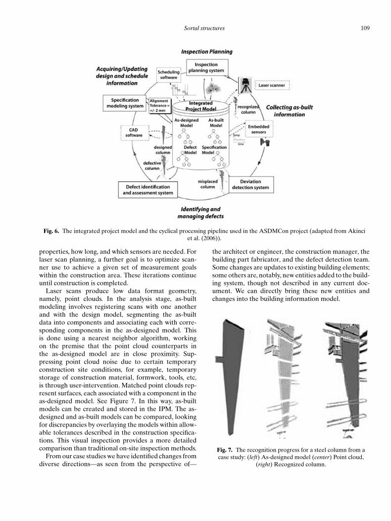
including 3D imagers (i.e., laser scanners) and embed-ded sensors are central to this assessment process. Laserscanners provide a capability of accurately modeling thegeometry of a facility, while embedded sensors monitornongeometric aspects, such as concrete strength. This in-formation is combined with a design model, an ontologyfor construction specification, and a project schedule tocreate an “integrated project model” (IPM), which is dy-namically updated throughout the construction period(Figure 6).
Research has shown that a semantically rich inte-grated project database combining the views of projectparticipants can support various project managementand facility management during the construction phase(Cleveland, 1996; Froese et al., 1999; Fischer et al., 1998;Yu et al., 1998). Accordingly, an important element ofour system is a capability of generating multiple viewsto serve the purposes of the different collaborators (andpotential users). From the outset, we have looked at sortstowards achieving this.
The team conducted four case studies on constructionsites near Pittsburgh, Pennsylvania. These case studiesserve to identify the challenges in applying a specificdesign representation to suit the different perspectivesfrom various objectives during the construction devia-tion identifying process (Gordon et al., 2003).
Overall, for each case study, the process starts withinformation gathering to build an IPM. The as-designedmodel has a level of geometric detail, useful for compar-ison, with features extracted from a current condition

106 Stouffs, Krishnamurti & Park
Fig. 3. UML implementation model of the classes in the “sort” package.
Sortal structures 107
Fig. 4. UML implementation model of a subset of the classes in the “ind” package.
of construction. For nongeometric features, componentsare presented with expected performance attributes thatcorrespond to gathered data. The sequence for thereality capturing process, comprises the iterative stepsdescribed below.
IPM initialization is based on architect-supplieddocuments, from which a building information model
is developed. This model is a resource for determiningmeasurement goals. Depending upon the property to bemeasured, goals are set for each specific sensing methodfor data collection. For example, goals with geometric in-formation use laser scanning to be able to compare spe-cific shapes from the as-designed and as-built models.Other properties, such as inside concrete temperature,

108 Stouffs, Krishnamurti & Park
Fig. 5. UML implementation model of the classes in the “form” package.
are measured by embedded sensing. Even when a prop-erty has no geometric relevance, distributing sensors ina building element requires dealing with the as-designedgeometry. Once measurement goals have been deter-
mined, planning for each method of data collection pro-ceeds. For a given construction schedule, as-designedmodel, and measurement goals, an embedded sensingplan is made by multiple decisions of when, where, what
Sortal structures 109
Fig. 6. The integrated project model and the cyclical processing pipeline used in the ASDMCon project (adapted from Akinci
et al. (2006)).
properties, how long, and which sensors are needed. Forlaser scan planning, a further goal is to optimize scan-ner use to achieve a given set of measurement goalswithin the construction area. These iterations continueuntil construction is completed.
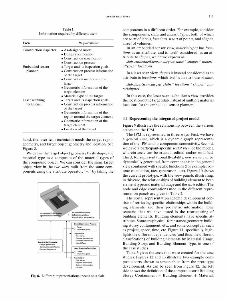
Laser scans produce low data format geometry,namely, point clouds. In the analysis stage, as-builtmodeling involves registering scans with one anotherand with the design model, segmenting the as-builtdata into components and associating each with corre-sponding components in the as-designed model. Thisis done using a nearest neighbor algorithm, workingon the premise that the point cloud counterparts inthe as-designed model are in close proximity. Sup-pressing point cloud noise due to certain temporaryconstruction site conditions, for example, temporarystorage of construction material, formwork, tools, etc,is through user-intervention. Matched point clouds rep-resent surfaces, each associated with a component in theas-designed model. See Figure 7. In this way, as-builtmodels can be created and stored in the IPM. The as-designed and as-built models can be compared, lookingfor discrepancies by overlaying the models within allow-able tolerances described in the construction specifica-tions. This visual inspection provides a more detailedcomparison than traditional on-site inspection methods.
From our case studies we have identified changes fromdiverse directions—as seen from the perspective of—
the architect or engineer, the construction manager, thebuilding part fabricator, and the defect detection team.Some changes are updates to existing building elements;some others are, notably, new entities added to the build-ing system, though not described in any current doc-ument. We can directly bring these new entities andchanges into the building information model.
Fig. 7. The recognition progress for a steel column from a
case study: (left) As-designed model (center) Point cloud,
(right) Recognized column.

110 Stouffs, Krishnamurti & Park
4.2 Modeling “changes” in the integratedproject model
The IPM is a learning repository, containing traces ofbuilding evolution from design to completion of con-struction, based on incomplete attribute information, inthe form of IFC data (though any data protocol willwork). To capture a current site condition, two new en-tities were added to the IPM: embedded sensor data,and as-built geometry from the laser scans. Entities areconnected through their as-designed element identity.Embedded sensor entities have as substratum, an as-designed element and a location within that element.Sensor entities contain other attributes, such as type, us-age, and time-stamped values. Each as-built geometricentity maps to an as-designed element. Ideally, this map-ping is one-to-one, from an as-built surface to a surfaceof an as-designed element. Also, a new entity named“Defect” was added into the IPM. The defect entityrelates as-designed and as-built elements through theiridentities. It may also include either or both sensor entityand as-built geometry.
The IPM was designed to capture both changes inthe as-designed model, and for a given constructionsite (as-built). The as-designed model contains compo-nent geometry as well as attributes data, such as mate-rial, install-start time, install-end time, etc. Defect andsensor data are attached to related components in theas-designed model. Change in the drawings implies anupdate of the as-designed model. All attribute and at-tached data are updated, or copied component by com-ponent. Data from any new updated version of theas-designed model is recorded in a different subdirec-tory from the previous version. Consequently, the IPMcontains history data (changes). An as-built model rep-resents whatever has been built on the construction site.It represents the latest recorded progress on the con-struction site, and thereby, records all changes on theconstruction site since the last scan session. In this way,each new scan session reflects an update of the as-builtmodel.
4.3 Modeling “different views” in the integratedproject model
For illustration, we provide three different views onthe IPM, namely, that of the construction inspector,embedded sensor planner, and laser scanning technician.It is important to note that when the as-designed modelis incorporated into the building construction process,information reflecting the construction specification,owner and construction contracts, construction processmodel, and so on, accumulate into the IPM.
The construction inspector decides upon measure-ment goals, to reason about deviations. For this, theconstruction specification, design specification, a de-tailed 3D as-designed geometry and construction pro-cess model are required. The information is categorizedaccording to the required properties. For instance, geo-metrical elements have to be visually recognizable, con-nectivity to other relevant elements clearly understood,and relevant information includes nongeometric datasuch as material type, construction process data and con-struction method.
An embedded sensor planner deals with planningand sensing of embedded sensors to collect data froma construction element. For this, element geometry,its location and construction process information arerequired. Furthermore, a construction method is speci-fied to relate material type to a specific time of instal-lation. The as-designed model does not contain suchinformation, and additional information is needed in theIPM.
To optimize scanner use to attain laser scan goals in thedynamically changing environment, the laser scanningtechnician employs a scanner path planner. From thepath planner’s perspective, construction site elementsare either obstacles or goals; the net objective is to pro-duce the shortest path for collecting data. The elementsinclude static building entities such as walls, columns,doors and so on, and temporary site entities such as scaf-folding, forms, temporary material stacks and so on. De-pending on the specific range of the laser scanner, goallocation and elevation are crucial. For example, the Z+Fscanner is capable of scanning 360◦ horizontally and 70◦
vertically with a maximum range of 25 m. For the Z+Fscanner, goals are kept to within that region to capturedata of sufficient quality to produce a three-dimensionalas-built model.
Table 1 summarizes the information required for thedifferent participants (views). The as-designed geometryis sufficiently rich enough to be able to generate infor-mation appropriate to the individual needs, for exam-ple, a full model view for the construction inspector,and a regional view for laser scanner path planning.As can be seen in the table, the requirements for thethree different views of the design model represent dif-ferent ways of serving as domain specific viewpoints.When a construction inspector decides upon the objectto be inspected, detailed information of the target is pro-vided to the other two actors. This includes the what,when, and where data that has to be collected to achievean inspection. The other two actors see the same ob-ject from their own perspective. The embedded sensorplanner needs geometric information, material type, andconstruction method of the target object. On the other
Sortal structures 111
Table 1Information required by different users
View Requirements
Construction inspector • As-designed model
• Design specification
• Construction specification
• Construction process
Embedded sensor • Target and its inspection goals
planner • Construction process information
of the target
• Construction methods of the
target
• Geometric information of the
target element
• Material type of the target
Laser scanning • Target and its inspection goals
technician • Construction process information
of the target
• Geometric information of the
region around the target element
• Geometric information of the
target element
• Location of the target
hand, the laser scan technician needs the target regiongeometry, and target object geometry and location. SeeFigure 8.
We define the target object geometry by its shape, andmaterial type as a composite of the material types ofthe compound object. We can consider the same targetobject view in the two sorts built from the same com-ponents using the attribute operator, “∧,” by taking the
Fig. 8. Different representational needs on a slab.
components in a different order. For example, considerthe components, slabs and materialtypes, both of whichare sorts of labels, locations, a sort of points, and shapes,a sort of volumes:
In an embedded sensor view, materialtypes has loca-tions as an attribute, and is, itself, considered, as an at-tribute to shapes, which we express as:
slab embeddedSensor targets: slabs ∧ shapes ∧ materi-altypes ∧ locations
In a laser scan view, shapes is instead considered as anattribute to locations, which itself is an attribute of slabs.
slab laserScan targets: slabs ∧ locations ∧ shapes ∧ ma-terialtypes
In this case, the laser scan technician’s view providesthe location of the target slab instead of multiple materiallocations for the embedded sensor planner.
4.4 Representing the integrated project model
Figure 9 illustrates the relationship between the variousactors and the IPM.
The IPM is represented in three ways. First, we havea general view, which is a dynamic graph representa-tion of the IPM and its component connectivity. Second,we have a participant-specific sortal view of the model,wherein sorts can be created, edited and/or modified.Third, for representational flexibility, new views can bedynamically generated, from components in the generalview combined with specific functions (for example, vol-ume calculation, face generation, etc). Figure 10 showsthe current prototype, with the view panels, illustrating,in this case, the relationships of building element to bothelement type and material usage and the sorts editor. Thenode and edge conventions used in the different repre-sentation panels are given in Table 2.
The sortal representation schema development con-sists of retrieving specific relationships within the build-ing elements, and their geometric information. Onescenario that we have tested is the restructuring ofbuilding elements. Building elements have specific at-tributes. Some are physical, for instance, geometry, build-ing storey containment, etc., and some conceptual, suchas project, space, time, etc. Figure 11, specifically, high-lights the different dependencies (and thus, the differentclassification) of building elements by Material Usage,Building Story, and Building Element Type, in one ofthe case studies.
Table 3 gives the sorts that were created for the casestudies. Figures 12 and 13 illustrate two example com-posite sorts, shown as screen shots from the prototypedevelopment. As can be seen from Figure 12, the leftside shows the definition of the composite sort: BuildingStorey Containment + Building Element + Material,

112 Stouffs, Krishnamurti & Park
Fig. 9. Relationship between the actors and IPM.
Fig. 10. Current prototype (left) view panels (right) sorts editor.
with the Building Element, graphically, as the focus ofattention. The right hand side shows the filtering of theproject database, corresponding to the Building Ele-ment, highlighting an instance and its related entities.
Figure 13 is interpreted in a similar manner. Throughsuch means we were able to easily filter the informa-tion specifically needed for laser scanning and defectdetection.

Sortal structures 113
Table 2Node and edge conventions in the prototype
Graphic representation (node)
View panel Color + Shape Example In IFC2×2 In Sorts
General Orange Rectangle Class name
Light Gray Ellipse Data (No outbound edges)
Dark Gray Circle Enumeration (Outbound edges)
Sorts Display/ Green Rectangle Primitive:
Edit Relationship
Green Circle Sum:
Function
Green Rectangle Attribute:
Function
New Rectangle Class Name
Ellipse Line Number (IfcBuildingElement)
Rectangle Line Number (Other than an
IfcBuildingElement)
Rectangle Relationship
Graphic representation (edge) In IFC2×2 In Sorts
A contains B From A to B
From our experiences with the case studies, it is clearthat there is a need to explicitly identify certain tar-get building elements. To pinpoint these target elementsfrom the rest of the building model, we embedded a
Fig. 11. Conceptual diagram of building elements dependencies.
string tag, “Target,” as the entity—Tag: IfcIdentifier—in the IfcBuildingElement class. The text in Figure 14shows a target tag in an IFC file, and a screen shot of thetarget element filtered from the building model.

114 Stouffs, Krishnamurti & Park
Table 3Example sorts defined for the construction case studies
Primitive sorts
Spatial structure Levels of decomposition in spatial structure for the building project (IfcSite,
IfcBuilding, IfcBuildingStorey, and IfcSpace)
Building Element Building elements in the building project
Building Type Building element type information in the building project
Building Story Containment Storey containment information in the building project
Material Material usage information in the building project
Target Target element information in the building project
Geometry Representation Geometry information in a building element
Sortal operators Name Function+ Sum Sum of primitive sorts∧ Attribute An attribute of building element
Composite sorts ExamplesBuilding Storey Containment + Building Element + Material
#133 ∧ Geometric Representation
Fig. 12. Composite sort: (Building Storey Containment + Building Element + Material): (left) Sorts Display/Edit panel; and
(right) New View panel.
Fig. 13. Composite sort: (#133 ∧ Geometric Representation): (left) Sorts Display/Edit panel; and (right) New View panel.

Sortal structures 115
Fig. 14. Target tagged building elements: (top) in the IFC file; (bottom) filtered in the New View panel.
5 CONCLUSION
We have presented a formal approach to representa-tional flexibility, sorts, for developing alternative rep-resentations of an entity, thereby supporting differentviewpoints, essential to any multi-disciplinary, multi-participatory endeavor such as the building domain.
We have highlighted this in addressing certain buildingconstruction related problems.
In the case studies, we were able to show the valueof sorts for its ability to flexibly modify/alter a represen-tational structure, through creation, update, and dele-tion of sortal relationships. There are three aspects ofsorts that we have illustrated through description andexamples.
Firstly, sorts support the specification of operationalbehavior of data in a uniform way. This specification isbased on a partial order, which enables: (1) the recogni-tion of components and structures that are not explicitlypresent in any current information (and its representa-tion); and (2) the restructuring of such information.
Secondly, sorts provide for two composition opera-tors: (1) an attribute operator that defines a convertibilityrelation that assists in indicating compatibility and dataloss, when conjunctive compositions of sorts are com-pared; and (2) a disjunctive composition operator thatdefines a subsumption relation, distinguished from theconjunctive attribute composition operator that does notadhere to the subsumption relation, quite distinct frommost first order logic-based representations.
Thirdly, sorts formally provide support for compar-ing representational structures with respect to scope and
coverage, to determine potential data loss whenever datais moved from less restrictive to more restrictive repre-sentations. In doing so, data loss is not necessarily an un-welcome side effect in exchange of information betweendifferent representations, rather, it can be the result ofa conscious deliberate decision that takes into accountany distinct advantage of the alternative views for theprocess under consideration.
ACKNOWLEDGMENTS
The first author is funded by the Netherlands Or-ganization for Scientific Research (NWO), grant nr.016.007.007; the second and third authors are fundedby a grant from the National Science Foundation, CMS#0121549. Both NWO’s and NSF’s support are grate-fully acknowledged. Any opinions, findings, conclusionsor recommendations presented in this article are thoseof the authors and do not necessarily reflect the views ofthe Netherlands Organization for Scientific Research orthe National Science Foundation. The authors would liketo thank Michael Cumming for his work on the develop-ment of a prototype interface to build and manipulatesorts.
REFERENCES
Aıt-Kaci, H. (1984), A lattice theoretic approach to computa-tion based on a calculus of partially ordered type structures(property inheritance, semantic nets, graph unification),Ph.D. dissertation, University of Pennsylvania, Philadelphia,PA.

116 Stouffs, Krishnamurti & Park
Akinci, B., Boukamp, F., Gordon, C., Huber, D., Lyons, C. &Park, K. (2006), A formalism for utilization of sensor systemsand integrated project models for active construction qualitycontrol, Automation in Construction, 15(2), 124–38.
Baader, F., Calvanese, D., McGuinness, D., Nardi, D. & Patel-Schneider, P. (2003), The Description Logic Handbook: The-ory, Implementation and Applications, Cambridge Univer-sity Press, Cambridge.
Cleveland, A. B. (1996), Integrating information with 3D mod-els for facility life-cycle support, in F. Y. Cheng (ed.), Analy-sis and Computation, American Society of Civil Engineers,Reston, VA.
Fischer, M., Aalami, F. & Akbas, R. (1998), Formalizing prod-uct model transformations: Case examples and applications,in I. Smith (ed.), Artificial Intelligence in Structural Engi-neering: Information Technology for Design, Collaboration,Maintenance, and Monitoring, Lecture Notes in Artificial In-telligence 1454, Springer, pp. 113–32.
Froese, T., Fischer, M., Grobler, F., Ritzenthaler, J., Yu, K.,Sutherland, S., Staub, S., Akinci, B., Akbas, R., Koo, B.,Barron, A. & Kunz, J. (1999), Industry Foundation Classesfor project management: A trial implementation, ElectronicJournal of Information Technology in Construction, 4, 17–36.http://www.itcon.org/1999/2(8 Dec. 2004)
Gordon, C., Boukamp, F., Huber, D., Latimer, E., Park, K. &Akinci, B. (2003), Combining reality capture technologiesfor construction defect detection: A case study, in B. Tuncer,S. Ozsariyildiz, and S. Sariyildiz (eds.), E-Activities in Build-ing Design and Construction, Europia, Paris, pp. 99–108.
ISO (1994), ISO 10303–1, overview and fundamental principles,International Standardization Organization, Geneva.
Kiviniemi, A. (2006), Ten years of IFC development – why arewe not yet there? Keynote lecture at the Joint InternationalConference on Computing and Decision Making in Civil andBuilding Engineering, Montreal, 14–16 June 2006.
Knight, T. W. (1989), Color grammars: Designing with lines andcolors, Environment and Planning B: Planning and Design,16(4), 417–449.
Knight, T. W. & Stiny, G. (2001), Classical and non-classicalcomputation, Architectural Research Quarterly, 5, 355–372.
Kolarevic, B. (2000), Digital Morphogenesis and Computa-tional Architectures, in J. Ripper Kos, A. Pessoa Borde, andD. Rodriguez Barros (eds.), Construindo n(o) espaco digital,PROURB, Universidade Federal do Rio de Janeiro, Rio deJaneiro, pp. 98–103.
Krishnamurti, R. (1992), The maximal representation of ashape, Environment and Planning B: Planning and Design,19(3), 267–288.
Krishnamurti, R. & Earl, C. F. (1992), Shape recognition inthree dimensions, Environment and Planning B: Planningand Design, 19(5), 585–603.
Krishnamurti, R. & Stouffs, R. (1997), Spatial change: Conti-nuity, reversibility and emergent shapes, Environment andPlanning B: Planning and Design, 24(3), 359–384.
Krishnamurti, R. & Stouffs, R. (2004), The boundary of a shapeand its classification, Journal of Design Research, 4(1).
Liebich, T., Ed. (2006), IFC 2x Edition 3, InternationalAlliance for Interoperability, http://www.iai-international.org/Model/R2×3 final/index.htm (23 Aug. 2006)
Mantyla, M. (1988), An Introduction to Solid Modeling, Com-puter Science Press, Rockville, MD.
Mitchell, W. J. (1993), A computational view of design creativ-ity, in J. S. Gero and M. L. Maher (eds.), Modeling Creativityand Knowledge-Based Creative Design, Lawrence ErlbaumAssociates, Hillsdale, NJ.
Rumbaugh, J., Jacobson, I. & Booch, G. (2005), The UnifiedModeling Language reference manual, 2nd Ed., Addison-Wesley, Boston.
Stiny, G. (1991), The algebras of design, Research in Engineer-ing Design, 2, 171–181.
Stiny, G. (1992), Weights, Environment and Planning B: Plan-ning and Design, 19(4), 413–430.
Stiny, G. (1993), Emergence and continuity in shape grammars,in U. Flemming and S. Van Wyk (eds.), CAAD Futures ‘93,North-Holland, Amsterdam, pp. 37–54.
Stiny, G. (1994), Shape rules: Closure, continuity, and emer-gence, Environment and Planning B: Planning and Design,21, s49–s78.
Stiny, G. (2006), Shape: Talking about Seeing and Doing, MITPress, Cambridge, Mass.
Stouffs, R. (1994), The Algebra of Shapes, Ph.D. dissertation,Carnegie Mellon University, Pittsburgh, PA.
Stouffs, R. (2006), Guest Editor, Artificial Intelligence in De-sign, Engineering and Manufacturing, Special Issue on De-sign Spaces: The Explicit Representation of Spaces ofAlternatives, 20 (2), May.
Stouffs, R. & Krishnamurti, R. (1996), On a query languagefor weighted geometries, in O. Moselhi, C. Bedard, and S.Alkass (eds.), Third Canadian Conference on Computing inCivil and Building Engineering, Canadian Society for CivilEngineering, Montreal, pp. 783–93.
Stouffs, R. & Krishnamurti, R. (2001), On the road to stan-dardization, in B. de Vries, J. van Leeuwen, and H. Achten(eds.), Computer Aided Architectural Design Futures 2001,Kluwer Academic, Dordrecht, The Netherlands, pp. 75–88.
Stouffs, R. & Krishnamurti, R. (2002), Representational flex-ibility for design, in J. Gero (ed.), Artificial Intelligence inDesign ‘02, Kluwer Academic, Dordrecht, The Netherlands,105–28.
Stouffs, R., Krishnamurti, R. & Eastman, C. M. (1996), A for-mal structure for nonequivalent solid representations, in S.Finger, M. Mantyla, and T. Tomiyama (eds.), Proceedings ofIFIP WG 5.2 Workshop on Knowledge Intensive CAD II, In-ternational Federation for Information Processing, WorkingGroup 5.2.
Woodbury, R., Burrow, A., Datta, S. & Chang, T. (1999), Typedfeature structures and design space exploration, Artificial In-telligence in Design, Engineering and Manufacturing, 13(4),287–302.
Yu, K., Froese, T. & Grobler, F. (1998), International al-liance for interoperability: Industry foundation classes, inK. Wang (ed.), Computing in Civil Engineering, Amer-ican Society of Civil Engineers, Reston, VA, pp. 395–406.
Yue, K., Huber, D. Akinci, B., & Krishnamurti, R. (2006), TheASDMCon project: The challenge of detecting defects onconstruction sites, Third International Symposium on 3DProcessing, Visualization and Transmission (3DPVT 2006),June.