Song, Wei-Zhang and Xing, Fei-Xiong and Yang, Hua and ...eprints.nottingham.ac.uk/46548/1/A Hybrid...
19
Song, Wei-Zhang and Xing, Fei-Xiong and Yang, Hua and Empringham, Lee and De Lillo, Liliana and Wheeler, Patrick and Li, Jie and Zhong, Yan-Ru (2015) A hybrid control method to suppress the three time fundamental frequency neutral-point voltage fluctuation in a VIENNA rectifier. IEEE Journal of Emerging and Selected Topics in Power Electronics, 4 (2). pp. 468-480. ISSN 2168- 6785 Access from the University of Nottingham repository: http://eprints.nottingham.ac.uk/46548/1/A%20Hybrid%20Control%20Method%20to %20Suppress%20the%20Three-Time%20Fundamental%20Frequency%20Neutral-Point %20Voltage%20Fluctuation%20in%20a%20VIENNA%20Rectifier.pdf Copyright and reuse: The Nottingham ePrints service makes this work by researchers of the University of Nottingham available open access under the following conditions. This article is made available under the University of Nottingham End User licence and may be reused according to the conditions of the licence. For more details see: http://eprints.nottingham.ac.uk/end_user_agreement.pdf A note on versions: The version presented here may differ from the published version or from the version of record. If you wish to cite this item you are advised to consult the publisher’s version. Please see the repository url above for details on accessing the published version and note that access may require a subscription. For more information, please contact [email protected]
Transcript of Song, Wei-Zhang and Xing, Fei-Xiong and Yang, Hua and ...eprints.nottingham.ac.uk/46548/1/A Hybrid...

Song, Wei-Zhang and Xing, Fei-Xiong and Yang, Hua and Empringham, Lee and De Lillo, Liliana and Wheeler, Patrick and Li, Jie and Zhong, Yan-Ru (2015) A hybrid control method to suppress the three time fundamental frequency neutral-point voltage fluctuation in a VIENNA rectifier. IEEE Journal of Emerging and Selected Topics in Power Electronics, 4 (2). pp. 468-480. ISSN 2168-6785
Access from the University of Nottingham repository: http://eprints.nottingham.ac.uk/46548/1/A%20Hybrid%20Control%20Method%20to%20Suppress%20the%20Three-Time%20Fundamental%20Frequency%20Neutral-Point%20Voltage%20Fluctuation%20in%20a%20VIENNA%20Rectifier.pdf
Copyright and reuse:
The Nottingham ePrints service makes this work by researchers of the University of Nottingham available open access under the following conditions.
This article is made available under the University of Nottingham End User licence and may be reused according to the conditions of the licence. For more details see: http://eprints.nottingham.ac.uk/end_user_agreement.pdf
A note on versions:
The version presented here may differ from the published version or from the version of record. If you wish to cite this item you are advised to consult the publisher’s version. Please see the repository url above for details on accessing the published version and note that access may require a subscription.
For more information, please contact [email protected]

1
Abstract—This paper presents a solution to the control of the three times fundamental frequency fluctuation of the neutral-point in a
VIENNA rectifier. A hybrid method combining a dynamic adjustment factor with a voltage deviation control of the split DC-link is
proposed. The fluctuation of the neutral-point has been analyzed and the reason for the three times fundamental frequency fluctuation
has been described using a mathematic model. As well as minimizing the three times fundamental frequency component in the
neutral-point voltage the proposed control method also provides immunity to the influence of changes in the capacitor voltage.
Furthermore, significant fluctuation in the neutral-point voltage caused by asymmetric capacitor parameters or unbalanced load can be
effectively reduced by using a hybrid control method combining additional adjustment coefficients. The feasibility and effectiveness of the
proposed strategy has been verified through the presented simulation and experimental results.
Index Terms—VIENNA rectifier; neutral-point fluctuation; hybrid control method; dynamic adjustment factor
I. INTRODUCTION
grid-connected voltage source pulse width modulated(PWM) rectifier has advantages over a diode bridge rectifier in terms of
having a low current total harmonic distortion (THD) as well as offering controllable supply side power factor (PF) [1]-[3]. In
comparison to the traditional two and three-level unidirectional PWM rectifiers [4]-[5], the VIENNA rectifier is reported to have the
advantages of: a simple power stage structure and control; low input current harmonics and low device voltage stress [6] -[9].
Therefore, they are widely used in telecommunications power systems, aircraft and medium-voltage drive systems, where
high-power density and low device voltage stresses are required [10]–[12].
The VIENNA rectifier belongs to the three-level voltage source converter family [13]–[14]. This three-level structure results in a
low blocking voltage stress on the power semiconductor devices and a small input inductor volume. However, it can also cause a
significant problem related to the fluctuation of the neutral-point voltage, which can cause unbalanced capacitor voltages leading to
A hybrid control method to suppress the three
times fundamental frequency neutral-point voltage
fluctuation in a VIENNA rectifier
A

2
increased stress on semiconductor devices and the generation of low-order harmonics in the input voltages and currents [15] –[16].
A series of suppression methods for neutral-point fluctuation in the VIENNA rectifier have been proposed [17]–[21], these methods
can be classified into the following categories:
Solutions based on the use of P and N short vectors[17] or redundant switching states[18];
Solutions based on the injection of zero-sequence or ripple components[18] ,[19];
Solutions with neutral-point voltage error feed-forward [20]–[22] where any deviation of the voltage across the two DC link
capacitors is added to the modulation waveform to suppress the neutral-point offset.
In [17], a hysteresis-band based method to eliminate the potential effect on the neutral-point according to the principle that the P
and N short vectors have the opposite effect on neutral-point voltage. However, this method relies on a complicated three-level
modulation strategy. In [18], the output voltage neutral-point was balanced by using a proper distribution of the local overall on-time
of the redundant switching during each half period. The input current however would be influenced in a negative way for an
asymmetric output load because of the change in the distribution of the switching states [18] resulting in increased low order
harmonics. Wang et al [18] used injected zero-sequence components to suppress the neutral-point fluctuation, but the calculation of
the zero-sequence components is very complex and difficult to realize in practice. A constant power control by injecting power
ripple was employed to eliminate the twice fundamental frequency ripple in the DC-link voltage in [20], however, it does not
consider the three times fundamental frequency fluctuation. Reference [21] describes a zero-sequence component injected
carrier-based SPWM with the equivalent voltage transfer ratio and voltage utilization ratio of SVPWM. This method avoided using
the complex three-level SVPWM strategy, but a large calculation effort is required for the zero-sequence components. A
feed-forward control method with neutral-point voltage error was used to improve neutral-point performance through employing a
fixed regulating factor in [22], however, the selection of regulating factor lacks theoretical basis and only depends on engineering
experience, furthermore, this scheme has some difficulty in reducing the three times fundamental frequency fluctuation. Reference
[22] proposed two further methods named active and passive voltage-balancing technology to balance the DC-link capacitor
voltages for a multi-pulse rectifier.
This paper presents a hybrid method combining a dynamic adjustment factor with a capacitance voltage deviation expression to
suppress the three times fundamental frequency neutral-point voltage fluctuations for the VIENNA rectifier. The feasibility and
effectiveness of the proposed strategy has been verified through simulation and experimental results.
II. NEUTRAL-POINT MATHEMATICAL MODEL IN A VIENNA RECTIFIER
Fig. 1 shows the circuit topology of the non-regenerative three-level VIENNA rectifier considered in this paper. The circuit is

3
comprised of a main diode bridge and three bidirectional switches connecting the input phases to the DC-link neutral-point. The
three active switching units are controlled to ensure sinusoidal input current and a steady DC-link voltage.
A. Reason of Neutral-point Voltage Unbalance
By analyzing the VIENNA rectifier circuit as shown in Fig.1, the relationship expression between voltage and current for the
DC-link capacitors can be described as
1
2
1 1
2 2
c
c
c
c
u
u
di C
dt
di C
dt
(1)
By integrating equation (1), the voltage of each capacitor can be written as follows:
1 1 1
0
2 2 20
1 1
2 2
( ) (0)
( ) (0)
t
c c c
t
c c c
i dt u u
i dt u u
C t C
C t C
1 1 10
1
2 2 20
2
1(0)
1(0)
( )
( )
t
c c c
t
c c c
u i dt uC
u i dt uC
t
t
(2)
Where ic1,ic2 and uc1(t), uc2(t) are the charge-discharge currents and voltages of DC-link capacitors of c1 and c2
respectively,uc1(0)and uc2(0) are the initial voltage of the two capacitors.
Seen from equation (2), the voltage of the capacitors is not only related to the initial capacitor voltage value, but also to the
charge-discharge currents in real time. The different manufacturing processes or stray parameters of capacitor can cause different
charge-discharge characteristics and equivalent impedances, which finally result in the form of capacitor voltage unbalance. In this
operating situation, the neutral-point current contains large amounts of AC fluctuation and DC offset components causing
neutral-point voltage unbalance [24]. Based on analyzing a large amount of references on developments and reports into
neutral-point unbalance, the neutral-point potential unbalanced forms and reasons can be categorized in Fig.2 [17-20] [22-24].
From Eqn.2, the neutral-point potential unbalance becomes present since the charge-discharge currents of the two capacitors is
not equal on average to zero, while neutral-point fluctuation is only the expression form of the charge-discharge current flow
sL
sL
sL
sau
sbu
scu
N
ai
bi
ci
o
n
1C
2C
oiSao
RL
D1 D2 D3
D4 D5 D6
cau
cbu
ccu
1ci
2ci
ppi
ni
Li
Sbo
Sco
uc1+-
+-uc2
Fig. 1. Topology of VIENNA rectifier
Neutral point
potential unbalanceDC offset
AC fluctuation
Asymmetric hardware
parameters
DC component
Charge-discharge characteristic
Equivalent impedance
Manufacturing process
1 2c ci i
Low frequency fluctuation: periodical change of
charge-discharge of two capacitors
High frequency fluctuation: asymmetric PWM or
switching delay
[16][18][22]
[17][19]
[17][21]
[19][22][23]
[18]
Fig. 2. The neutral-point potential unbalanced forms

4
through the capacitors .
Therefore, it is necessary to develop mathematical model for the neutral-point current to study the changing trend of neutral-point
charge-discharge currents so that an effective method to suppress neutral-point fluctuation can be found.
B. Neutral-point Current Mathematical Model
In order to simplify the analysis, the following assumptions have been made:
1) DC-link output voltage is regarded as ideal DC voltage source;
2) Input voltage and modulation signal are three phase balanced;
3) Power switches and lines are regarded as ideal components.
As shown in Fig.1, current equations of node p,o and n can be derived according to the Kirchhoff’s current law as follows:
1
1
1 1
p c L
c
c
i i i
dui C
dt
(3)
2
2
2 2
n c L
c
c
i i i
dui C
dt
(4)
2 1
1 2 2 1( ) c c
o c c
o ao a bo b co c
du dui i i C C
dt dt
i s i s i s i
(5)
Sjo represents the switching functions and can be defined as:
0
1
1jo
s
Sjo on
Sjo off and usj>0
Sjo off and usj<0
j=a,b,c
(6)
To simplify the analysis, the initial voltage of capacitor is ignored, so, uc1= uc1(t), uc2= uc2(t), and by integrating from equation (5),
we have
0 0
2 2 1 1
t t
o ao a bo b co cc c i dt s i s i s i dtC u C u (7)
Seen from equation (7), the reason for neutral-point potential voltage fluctuation is caused by the non-zero neutral-point current
derived from the high frequency charge-discharge of DC-link capacitors.
5
C. The Three Times Fundamental Frequency Fluctuation of Neutral-point Current
In order to simplify the analysis, the value of C1 is set to be equal to C2, using the fundamental functions of high frequency switch
instead of high frequency switching functions in the equation (5), so the fundamental model of neutral-point current can be obtained
as:
2 1( )
(1 ) (1 ) (1 )
c c
o
o ma a mb b mc c
du dui C
dt dt
i u i u i u i
(8)
Where uma,umb and umc are the three phase input voltage reference signals which are in phase with three phase grid-side voltages,
respectively
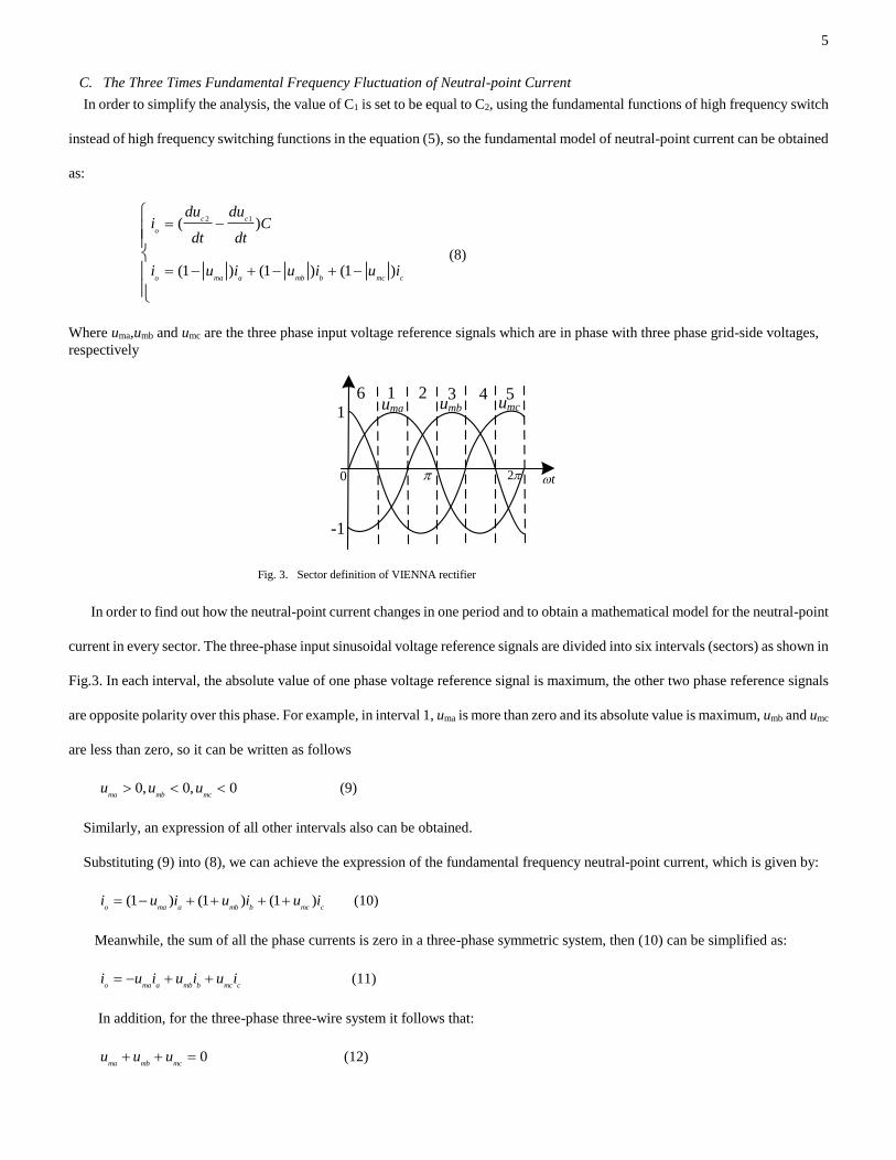
In order to find out how the neutral-point current changes in one period and to obtain a mathematical model for the neutral-point
current in every sector. The three-phase input sinusoidal voltage reference signals are divided into six intervals (sectors) as shown in
Fig.3. In each interval, the absolute value of one phase voltage reference signal is maximum, the other two phase reference signals
are opposite polarity over this phase. For example, in interval 1, uma is more than zero and its absolute value is maximum, umb and umc
are less than zero, so it can be written as follows
0, 0, 0ma mb mc
u u u (9)
Similarly, an expression of all other intervals also can be obtained.
Substituting (9) into (8), we can achieve the expression of the fundamental frequency neutral-point current, which is given by:
(1 ) (1 ) (1 )o ma a mb b mc c
i u i u i u i (10)
Meanwhile, the sum of all the phase currents is zero in a three-phase symmetric system, then (10) can be simplified as:
o ma a mb b mc ci u i u i u i (11)
In addition, for the three-phase three-wire system it follows that:
0ma mb mc
u u u (12)
0
1 2 3 4 56uma umb umc1
-1
t 2
Fig. 3. Sector definition of VIENNA rectifier

6
When the input current is in phase with grid side voltage in a steady state system with a closed-loop control, the instantaneous
phase current can be described as [22]:
, , ,j mj
i k u j a b c (13)
Where k is the ratio coefficient between the current and reference voltage amplitude, which is a constant positive value. j
indicates the three-phase input, which can be a, b or c.
With (11), (12) and (13), the neutral-point fundamental frequency current is given by:
2o mb mc
i ku u (14)
In sector 1, umb and umc have the same polarity, so it follows that:
0oi (15)
Equation (15) shows that the fundamental frequency component of the neutral-point current is less than zero in sector.1, where
the DC-link capacitor C1 charges and C2 discharges, furthermore, the voltage of capacitor C1(Uc1) is greater than the voltage of
capacitor C2(Uc2).
The expressions of neutral-point current and relationship between two capacitors in the other five sectors can be obtained as listed
in Tab. I in the same way. Seen from Tab. I, the neutral-point current can be expressed as the product of two sinusoidal signals,
which only equal zero at the beginning and end of the sector and change with a sinusoidal tendency in real time, the neutral-point low
frequency voltage fluctuation becomes present since these low frequency distortion signals of neutral-point current are not always
equal to zero.
III. HYBRID METHOD TO SUPPRESS NEUTRAL-POINT FLUCTUATION
A. NEUTRAL-POINT DYNAMIC ADJUSTMETND FACTOR METHOD
Seen from Fig.1, the voltage deviation of the DC-link two capacitors (neutral point voltage deviation) can be expressed as
2 1uc c cU U
(16)
Reference [22] used a method based on this neutral point voltage deviation with a fixed adjustment factor to compensate the
TABLE I
NEUTRAL-POINT CURRENT EXPRESSIONS AND ITS EFFECT IN EACH SECTOR
Sector Neutral-point current
expressions
Charge and discharge of two capacitors or
Voltage relationship between two capacitors
1 io=-2kumbumc<0 charge C1, discharge C2, Uc1>Uc2
2 io=2kumbuma>0 dischargeC1,chargeC2, Uc1<Uc2
3 io=-2kumaumc<0 chargeC1,dischargeC2, Uc1>Uc2
4 io=2kumbumc>0 dischargeC1,chargeC2, Uc1<Uc2
5 io=-2kumbuma<0 chargeC1,dischargeC2, Uc1>Uc2
6 io=2kumaumc>0 dischargeC1,chargeC2, Uc1<Uc2
7
neutral point voltage fluctuation, however, this conventional fixed adjustment factor method has some difficulty in reducing the low
frequency neutral point fluctuations.
The low frequency neutral point fluctuation would be eliminated if this neutral-point voltage deviation could be adjusted by using
an appropriate dynamic adjustment factor [22]. For this reason a method with a dynamic adjustment factor is deduced as follows:
In the first sector as shown in Fig.3, substituting the neutral-point voltage offset with adjustment coefficient md as a compensation
component into (10), the neutral-point current can be described as follows:
' (1 ) (1 ) (1 )o ma uc a mb uc b mc uc cd d di u m i u m i u m i (17)
With (10), (12) and (13), then (17) can be simplified as
' 2o o ma ucdi i m ku (18)
With the introduction of neutral-point deviation, a further part can be added to the neutral-point current fundamental expression
reducing neutral-point current amplitude and restraining the neutral-point voltage offset.
From the analysis in section II, the neutral-point voltage fluctuation becomes present where the fundamental frequency
components of the neutral-point current are not equal to zero. Therefore, if (18) is equal zero, then the neutral-point current
fundamental frequency components are always constant and zero, thus the neutral-point offset could be theoretically eliminated and
the neutral-point fluctuation would be removed, combing (14), we have:
mb mc
ma uc
d
u um
u
(19)
Where md is the dynamic adjustment factor for neutral-point. From this equation, the dynamic adjustment expression can be
resolved, and its expression can be deduced as follows:
mb mcmd d uc
ma
u uu m
u (20)
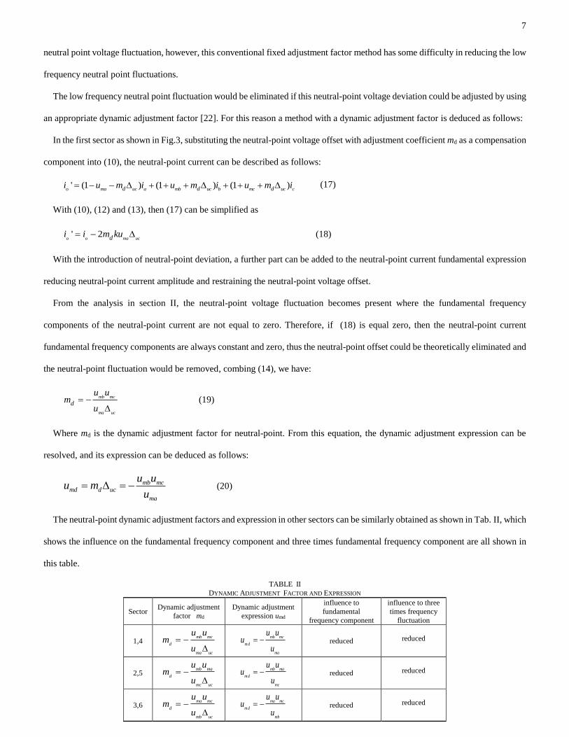
The neutral-point dynamic adjustment factors and expression in other sectors can be similarly obtained as shown in Tab. II, which
shows the influence on the fundamental frequency component and three times fundamental frequency component are all shown in
this table.
TABLE II DYNAMIC ADJUSTMENT FACTOR AND EXPRESSION
Sector Dynamic adjustment
factor md
Dynamic adjustment
expression umd
influence to
fundamental
frequency component
influence to three
times frequency
fluctuation
1,4 mb mc
d
ma uc
u um
u
mb mc
m d
ma
u uu
u reduced
reduced
2,5 mb ma
d
mc uc
u um
u
mb ma
m d
mc
u uu
u reduced
reduced
3,6 ma mc
d
mb uc
u um
u
ma mc
m d
mb
u uu
u reduced
reduced

8
B. HYBRID METHOD TO SUPPRESS NEUTRAL-POINT FLUTUATION COMBINING A DYNAMIC ADJUSTMENT
FACTOR AND CAPACITOR VOLTAGE DEVIATION
Equation (19) is a theoretical condition to eliminate the offset of neutral-point, which requires that the value of the dynamic
adjustment factor is close to infinite as shown in the following, but that is impossible to achieve, in other words, the value of the
dynamic adjustment factor method is decided by the deviation of neutral point itself in order to suppress neutral-point fluctuations.
So this method can not eliminate but only decrease the neutral-point potential fluctuation. To achieve a better performance for
neutral point control, a hybrid method combining a dynamic adjustment factor with capacitor voltage deviation is proposed and
deduced as follows.
0
lim( )uc
mb mc
ma uc
d
u um
u
(21)
The hybrid neutral point control method consists of two parts: the actual neutral-point deviation um0 and the dynamic adjustment
expression umd including the dynamic adjustment factor,then the hybrid adjustment expression um can be expressed as follows:
0m m mdu u u (22)
In the first sector as shown in Fig.3, the dynamic adjustment expression is shown in equation (20). If not considering the influence
of asymmetric capacitance parameters or unbalanced load, um0 can be written as:
0 2 1m uc c cu U U (23)
Where um0 is the voltage deviation of DC-link two capacitors.
After substituting (20) and (23) into (22), um can be re-written
(1 )mb mc mb mc
m uc uc
ma ma uc
u u u uu
u u
(24)
Similarly, expressing in equation (20), the hybrid adjustment factor m can be developed as
1mb mc
ma uc
u um
u
(25)
The neutral-point hybrid adjustment factor and adjustment expression in remaining sectors can be similarly obtained as shown in
PI-
PIdi
2r /2s
-+
+
VIENNAsau
load
3s /2s
3s /2s
PI
PWM
PLL
-
dcu
*dcu
ai
bi
cisbu
scun
iL
+ +
-+2s /3s
++
++
++
uc2
sL
+-
uc1
mamb
mc
c1
c2
uc2
uc1+ +
um
-
Table
Ⅲ
uma
umb
umc
Δucsu su
0qi
*i*i
su
su
i i
Magnitude
adjustment
o
n
p
Fig.4 The dual closed loop control system block diagram based on hybrid neutral-point control method

9
Table. III. The dual closed loop control system based on hybrid neutral-point suppression method in a VIENNA rectifier is shown
in Fig.4. Through the above analysis and Fig.4, it can be seen that the neutral point fluctuation of VIENNA rectifier would be
effectively eliminated using proposed hybrid neutral point control method combining the capacitor voltage deviation with dynamic
adjustment factor based on a closed loop control. Moreover, seen from Table. III , the neutral point fluctuation control only needs
a simple look up table instead of the need for any complex computations, which renders this method very suitable for
implementation in a real controller.
However, the neutral-point fluctuation would become more significant under abnormal condition such as asymmetric capacitor
parameters or unbalanced DC-side load, so the additional adjustment coefficient k1 is needed to be introduced to equation (22) in
order to reduce the influence caused by the abnormal condition, and then the following equation can be obtained:
0 1'm uc
u k (26)
Substituting (26) into (24)-(25), the improved hybrid adjustment factor and expression to reduce the neutral-point fluctuation for
this abnormal condition in sector 1 are shown in equation (27) and (28), the equations in other sectors can be obtained similarly and
omitted here because of limited length for the paper.
1'mb mc
ma uc
u um k
u
(27)
1' ( )mb mc
m uc
ma uc
u uu k
u
(28)
C. IDEAL WAVEFORMS ANALYSIS FOR NEUTRAL-POINT FLUTUATION SUPPRESSION METHOD
The equivalent circuit of single-phase VIENNA rectifier is shown in Fig.5 [8]. Seen from Fig.5, the VIENNA rectifier features
a boost characteristic as mentioned in reference [26], Reference [27] presents an equivalent circuit model for the boost topology
using dependent current and voltage sources as shown in Fig.6. Seen from Fig.1, when the switch is on, the inductor is charged
supplied by the power supply, then this operating state can be regarded as a current source [27], when the switch is off, the DC-link
capacitors would be charged through the uncontrollable rectifier bridge supplied by the power supply, then its equivalent is a voltage
source. Meanwhile the three phase VIENNA rectifier is comprised of three single-phase VIENNA rectifiers in a parallel output [1]
[21], hence, the equivalent circuit of three phase VIENNA rectifier also consists of the equivalent model of three single phase
TABLE III HYBRID ADJUSTMENT FACTORS AND EXPRESSIONS
Sector Hybrid adjustment factor
m=m0+md
Hybrid adjustment expression
um=um0+umd
1,4 1mb mc
ma uc
u um
u
mb mc
m uc
ma
u uu
u
2,5 1mb ma
mc uc
u um
u
mb ma
m uc
mc
u uu
u
3,6 1mc ma
mb uc
u um
u
mc ma
m uc
mb
u uu
u

10
VIENNA rectifiers in parallel as shown in Fig 7. Seen from Fig.7, the neutral point current is controlled by the current source using
a switch meanwhile the capacitor voltage is decided by the voltage source.
Combining Fig.1 with the table I, the ideal waveform of neutral-point current io can be drawn as shown in Fig.8, the neutral-point
current presents a three times fundamental fluctuation. Since the neutral-point current is phase-shifted by 900 to the deviation of the
two DC-link capacitors because of the capacitor characteristics, then the capacitor voltage deviation can be obtained as shown in the
third waveform of Fig.8. According to table II, the waveform of dynamic adjustment expression umd is also shown in Fig.8,
presenting a AC signal with the same frequency and phase with io, umd is added to the modulated signal and used to generate the
PWM waveform urmd as shown in Fig.8. Seen from Fig.8, the urmd pulse width is inversely proportion to the io magnitude, then this
results in a compensation for the neutral-point current fluctuation. Similarly, according to table III, the hybrid expression um is
drawn in the sixth waveform as well as its corresponding PWM is shown in the seventh waveform in Fig.8. Fig.8 also shows the
pulse width of urm is inversely proportion to the magnitude of um
consisting of a voltage deviation with a dynamic adjust
expression, thus, the fluctuation of capacitor voltage deviation
and neutral-point current can all be compensated by using this
PWM generated by um.
sL
sau
N
D1
D4
Sao
o o
1C
2C
n
p
1ci
2ci
RL
Licau
Fig.5 The equivalent circuit of phase a for VIENNA rectifier
0
1 2 3 4 56uma umb umc
1
-1
t
i o(A
)(
)uc
V
Io
-Io
c
c
um
j(V
)u
md(V
) Ud
-Ud
1
urm
d(V
)u
m(V
)
Um
-Um
urm
(V)
1
t
t
t
t
t
t
Fig.8 The ideal waveforms of neutral point current, capacitor voltage
deviation and adjustment expression

11
IV. EXPERIMENT RESULTS
A power converter prototype was built to verify the validation of the proposed neutral-point balance control strategy, which is
shown in Fig.9, the closed loop control and hybrid neutral-point control method combining a dynamic adjustment factor with
capacitor voltage deviation expression were all carried out using a 32-bit DSP type TMS320F2812 operating at a clock frequency of
150MHz, the experimental parameters are shown in Table IV. The VIENNA rectifier belongs to the three-level voltage source
converter family, one of control objectives for multi-level converter is to achieve the low current THD with a low switching
frequency, further reducing switching losses, which is the reason of using a low switching frequency shown in table IV.
o
n
1C
2C
oi
RL
1ci
2ci
ppi
ni
Liapu
anu
cnu
+_
+_
cau
Fig.6 The equivalent circuit of three phase VIENNA rectifier
o
n
1C
2C
oi
RL
cau
1ci
2ci
ppi
ni
Li
cbuccu
apubpu cpu
anubnu cnu
aoi
boi
coi
+_ +_ +_
+_ +_ +_
ujp
(V)
t
Fig.7 The equivalent circuit of three phase VIENNA rectifier
DSP Board
Power circuit
Detect board
Power supply
board
DC-link board
Fig.9 Experimental prototype
TABLE IV SYSTEM PARAMETERS
parameter value
Grid-voltage
DC-link voltage reference
Load resistor
Switching frequency
AC filter inductor
DC-link filter capacitor
100V/50Hz
200V
800-120Ω
4.8kHz
8mH
1600 μF

12
Fig.10 shows the comparison waveforms between conventional fixed adjustment factor and proposed hybrid method, ic is the
input phase current of phase C. Using the conventional method with only a fixed adjustment factor, it can be seen that the voltage of
DC-link two capacitors aren’t the same and the voltage deviation of three times fundamental frequency component is up to ±0.75V,
however, with the proposed hybrid method combining a dynamic adjustment factor with capacitor voltage deviation expression, the
voltage deviation of three times fundamental frequency component is decreased from ±0.75V to ±0.15V and then the neutral-point
voltage fluctuation is also effectively reduced, which verifies the validity of proposed scheme.
A. Abnormal operating condition (asymmetric capacitor parameter and unbalanced load)
It is possible that capacitor parameters change because of different manufacturing processes or long-term fatigue, causing
significant voltage offsets between the DC-link capacitors. To emulate this abnormal condition, two kinds of capacitors with
different capacitance and manufacture are employed (C1 is 1100μF with two CEB 2200μF/400V series, C2 is 1650μF consists of two
Jianghai company 3300μF/450V series). Similarly, two different resistors (R1:74 Ω, R2: 106 Ω) are used to emulate the unbalanced
load, then the equivalent circuit is shown in Fig.11.
t(5 ms/div)
Uc1
, U
c2
(1V
/div
)
Uc1
-Uc2
(1V
/div
)
i c(5
A/d
iv)
Uc1-Uc2
Uc1Uc2
ic
Uc1-Uc2
Uc1 Uc2
ic
Uc1
, U
c2
(1V
/div
)
Uc1
-Uc2
(1V
/div
)
i c(5
A/d
iv)
t(5 ms/div)
(a) Conventional method (b) Hybrid method
Fig.10 The comparison waveforms between conventional fixed factor and hybrid method
o
n
1C
2C
oi
1ci
2ci
p
1100μF
1650μF
74Ω
106Ω
R1
R2
Fig.11 The DC-side equivalent circuit of asymmetric capacitor and unbalanced load

13
Fig.12 (a), (b) shows a comparison waveforms between conventional fixed adjustment factor and the improved hybrid method
combining the additional adjustment coefficient under this abnormal condition. Using the conventional method of fixed adjustment
factor, the voltage deviation Uc1-Uc2 of the two DC-link capacitors does not only contain DC offset, but it also introduces large
amounts of three times fundamental frequency fluctuation component. After employing the improved hybrid method combining an
additional adjustment coefficient, the three times fundamental frequency component is effectively reduced and the remained DC
component is used to compensate for the neutral-point offset caused by asymmetric capacitor parameters or unbalanced load and
ensure a balanced neutral-point voltage. The DC component of Uc1-Uc2 is removed in order to observe this low frequency
fluctuation using AC coupling of the scope measurement channel as shown in Fig.12 (c), (d), it is also clear to see that the three times
fundamental fluctuation can be effectively decreased using the improved hybrid method, which is a significant fluctuation when
using conventional control methods.
Fig.13 shows the influence of neutral-point voltage deviation caused by asymmetric capacitor and unbalanced load with different
control methods. From the comparison of the results, it can be seen that the neutral-point voltage deviation is significant when using
Uc1
, U
c2
(20V
/div
)
Uc1
-Uc2
(5V
/div
)
i c(5
A/d
iv)
t (5 ms/div)
ic
Uc1
Uc2
Uc1-Uc2
Uc1
, U
c2
(20
V/d
iv)
Uc1
-Uc2
(5V
/div
)
i c(5
A/d
iv)
ic
Uc1-Uc2
Uc1
Uc2
t(5 ms/div)
(a) Conventional method (b) Improved hybrid method
t(5 ms/div)
Uc1
, U
c2
(1V
/div
)
Uc1
-Uc2
(1V
/div
)i c
(5A
/div
)
ic
Uc1-Uc2
Uc2Uc1
ic
Uc1-Uc2
Uc2Uc1
Uc1
, U
c2
(1V
/div
)
Uc1
-Uc2
(1V
/div
)i c
(5A
/div
)
t(5 ms/div)
(c) Conventional method (d) Improved hybrid method
Fig. 12 The comparison waveforms between conventional fixed factor and improved hybrid algorithm ( (c),(d): scope with AC channel)
Fixed adjustment
factor
ic
Uc1-Uc2
Uc2
Uc1
Uc1
,Uc2
(20V
/div
)
Uc1
-Uc2
(5V
/div
)
i c(5
A/d
iv)
t(1 s/div)
Hybrid methodImproved hybrid
method
Fig.13 The influence comparison of neutral-point voltage deviation caused by asymmetric capacitor and unbalanced load with different control methods

14
the conventional method of fixed adjustment factor, but by applying the hybrid method combining the dynamic adjustment factor
and capacitor voltage deviation expression, the neutral-point voltage deviation is effectively reduced, however, the neutral-point
voltage deviation is eliminated through using the improved hybrid method combining an additional adjustment coefficient.
Fig.14(a) and (b) show the input phase voltage,phase currents and output DC-link voltage. It can be seen that the input phase
current is in phase with the input voltage resulting in a 0.99 input power factor obtained by experiment measurement. Moreover, the
three-phase input currents are still sinusoidal and balanced under the proposed hybrid neutral-point control method.
Fig.15 shows the harmonic magnitude with and without proposed hybrid neutral point balancing control method, obtained using
a power analyzer. Comparing the results it can be seen that the fundamental frequency current magnitude is increased as well as the
current THD decreases from 4.21% to 3.8% using the proposed neutral point control method. Fig.16 shows a harmonic comparison
using a relative value with and without proposed hybrid neutral point balancing control method. The low frequency harmonic caused
by unbalanced capacitor voltage such as twice, third harmonics are greatly reduced, but the fourth, fifth, seventh, eleventh, thirteenth
seventeenth harmonics are increased due to the deviation of the switching pulses. Fig.16 confirms that the proposed method
effectively reduces low frequency input current harmonics, but at the expense of adding high-order harmonics, fortunately, these are
easy to be filtered using a common filter.
Fig.17 (a), (b) shows the dynamic response waveforms of input phase current and output voltage when the steps from 70%load to
100%load and recovers to70%load. Seen from the waveform, the output voltage is maintained constant even though changes of the
load. The constant DC component of output voltage is removed in order to observe this transient change using the AC coupled scope
measurement channel shown in Fig.17 (b), it can be seen that output voltage recovers to steady state within 0.15s under the condition
of transient adding 30%load, which shows the system with the proposed hybrid neutral-point control still exhibits a fast response to
load disturbance.
t(5 ms/div)
i c(5
A/d
iv)
U
dc ,
Usc
(50
V/d
iv) Udc
ic
Usc
t(5 ms/div)
ia
,ib ,
i c(5
A/d
iv)
(a) Input phase voltage, current and output voltage (b) Three phase input currents
Fig. 14 The input voltage, current and output voltage waveforms under proposed hybrid neutral-point control method

15
(a) Without neutral-point balancing control (b) hybrid neutral-point balancing control method
Fig. 15 The harmonic magnitudes without and with proposed hybrid neutral-point balancing control method
0
0.5
1
1.5
2
2.5
3
3.5
4
1 2 3 4 5 6 7 8 9 10 11 12 13 14 15 16 17 18 19 20 21 22 23 24 25 26 27 28 29 30 31 32 33 34 35 36 37 38 39 40
Without neutral-point balancing control
Hybrid neutral-point balancing control method
Harmonics order n
I(n),
pu(%
)
Towards 100%
Fig. 16 The input current harmonic relative value without neutral-point and with hybrid neutral-point balancing control method
t(100 ms/div)
i c(2
A/d
iv)
U
dc
(50V
/div
) Udc
ic0.15s
2V
Udc
ic
i c(2
A/d
iv)
U
dc
(5V
/div
)
t(100 ms/div)
(a) Response when steps from 70%load to 100%load and recovers to 70%load (b) Special observing for dynamic response using scope coupling with AC channel
Fig. 17 The input and output waveforms under proposed hybrid neutral-point control method

16
B. Light load operating condition
Fig.18 shows the comparison waveforms between conventional fixed adjustment factor and proposed hybrid method under a
light load operating condition with 100W output power as mentioned in [26]. From the comparing of the results, it can be seen that
the three times fundamental frequency fluctuation component is effectively reduced using the proposed hybrid method even in a
light load operating condition. But the input currents include more total harmonic distortion (THD) caused by working in the
discontinuous conduction mode (DCM) in the light load condition [26]. This increased THD of input currents can be reduced using
an enhanced control scheme as shown in [24]. Meanwhile, the VIENNA rectifier features an increased output voltage characteristic
easily causing an overvoltage protection under the light load and especial for a no-load operating condition as mentioned in [28]. A
specific circuit or control strategy should be used to make the system will work normally and remove the increased THD of input
currents in these operating conditions, these are the author’s future work.
V. CONCLUSION
This paper has presented a hybrid neutral-point balance control method combining a dynamic adjustment factor with a capacitor
voltage deviation expression to solve the problem of neutral-point fluctuation in a VIENNA type three-level rectifier. Using a
looking up table for capacitor voltage deviation and dynamic adjustment factor expression in the six input sectors, the neutral-point
fluctuation can be effectively suppressed, so the influence of DC deviation in the DC-link capacitor voltage can be eliminated.
Furthermore, significant fluctuation of neutral-point voltage caused by abnormal conditions such as asymmetric capacitor
parameters or unbalanced loads can be reduced by employing the improved hybrid method, combining an additional adjustment
coefficient. Moreover, the system after being introduced the proposed method still exhibits a low input current total harmonic
distortion (THD), high displacement factor and fast response to load disturbance. In addition, the algorithm only needs a look up
table, effectively removing the need for complex calculations which makes this method very suitable for practical implementation.
ACKNOWLEDGMENT
This work was supported by National Natural Science Foundation of China (51307138), Research Fund for the Doctoral Program
of Higher Education of China (20126118120009), State Key Laboratory of Electrical Insulation and Power Equipment
Uc1
, U
c2
(20
V/d
iv)
Uc1
-Uc2
(5V
/div
)i c
(5A
/div
) ic
Uc1-Uc2
Uc1
Uc2
t(5 ms/div)
Uc1
, U
c2
(20V
/div
)
Uc1
-Uc2
(5V
/div
)i c
(5A
/div
) ic
Uc1-Uc2
Uc1
Uc2
t(5 ms/div)
(a) Conventional method (b) Hybrid method
Fig.18 The comparison waveforms between conventional fixed factor and hybrid method under 100W output power

17
(EIPE14207), doctor foundation of Xi’an University of technology (105-211104), special foundation of key disciplines of Shaanxi
provincial project (105-5X1201)
REFERENCES
[1] Johann W.Kolar, Thomas.Friedli. “The essence of three-phase PFC rectifier systems-Part I ”. IEEE Trans.Power.Electron, vol.28, no.1, pp.176-198,Jan.2013.
[2] Patrick.W.Wheeler, José Rodríguez, Jon C.Clare,Lee.Empringham,and Alejandro.Weinstein. “Matrix converters: A technology review”. IEEE Trans.Ind.Electron,
vol.49, no.2, pp.276-288,Apr.2002.
[3] Jacobus Daniel van Wyk and Fred C. Lee, “On a Future for Power Electronics”, IEEE J. Emerg. Sel. Topics Power Electron, vol.1, no.2, pp. 59-72, June.2013.
[4] Weizhang Song, Yanru Zhong,Hao Zhang,Xiangdong Sun,Qi Zhang,Wei Wang, “A Study of Z-Source Dual-Bridge Matrix Converter Immune to Abnormal Input
Voltage Disturbance and with High Voltage Transfer Ratio,” IEEE Trans. Ind. Inform, vol. 9, no. 2, pp. 828–838, May. 2013.
[5] Thomas Friedli, Michael Hartmann, and Johann W. Kolar, “The essence of three-phase PFC rectifier systems—Part II,” IEEE Trans.Power.Electron, vol. 29, no. 2, pp.
543–560, Feb. 2014.
[6] Johann W. Kolar and Franz C. Zach, “A novel three-phase utility interface minimizing line current harmonics of high-power telecommunications rectifier modules,”
IEEE Trans. Ind. Electron, vol. 44, no. 4, pp. 456–467,Aug. 1997.
[7] R.Ansari,M.R.Feyzi,K.Akbari Hamed.N.Sadati,Y.Yasaei,S.Ouni, “Input-Output linearization of a fourth-order input-affine system describing the evolution of a
three-phase/switch/level(Vienna) rectifier,” IET Power. Electron, vol. 4,Iss. 8, pp. 867–883, May. 2010.
[8] Lijun Hang, Ming Zhang, Leon M.Tolbert,Zhengyu Lu, “Digitized feedforward compensation method for high-power-density three-phase Vienna PFC converter,” IEEE
Trans. Ind. Electron, vol. 60, no. 4, pp. 1512–1519, April. 2013.
[9] June-Seok Lee and Kyo-Beum Lee. “Carrier-Based Discontinuous PWM Method for Vienna Rectifiers”. IEEE Trans.Power.Electron, vol.30,no.6,
pp.2896-2900,June.2015.
[10] Kolar W. Johann, Franz C. Zach. “A novel three-phase utility interface minimizing line current harmonics of high-power telecommunications rectifier modules,” Proc
IEEE Int Commun Energy Conf, Vancouver, BC, Canada,Nov,1994, pp.367-374.
[11] Lijun Hang, Hao Zhang, Sensen Liu.Xiaogao Xie,Chen Zhao,Shirong Liu, “A Novel Control Strategy Based on Natural Frame for Vienna-Type Rectifier Under Light
Unbalanced-Grid Conditions,” IEEE Trans. Power. Electron, vol. 62, no. 3, pp. 1353–1362, Mar. 2015.
[12] M. Hartmann, S. D. Round, H. Ertl, and J. W. Kolar, “Digital current controller for a 1 MHz, 10 kW three-phase VIENNA rectifier,” IEEE Trans. Power Electron., vol.
24, no. 11, pp. 2496–2508, Nov. 2009.
[13] Rolando Burgos, Rixin Lai, Yunqing Pei, Fei(Fred) Wang,Dushan Boroyevich,Josep Pou.“ Space Vector Modulator for Vienna-Type Rectifiers Based on the
Equivalence Between Two-and Three-Level Converters: A Carrier-Based Implementation”. IEEE Trans. Power. Electron,Vol.23,no.4, pp.1888-1898,July,2008.
[14] J Alahuhtala, J Virtakoivu, T Viitanen,M.Routimo,H.Tuusa. “Space Vector Modulated and Vector Controlled Vienna I Rectifier with Active Filter Function,” In
Proceeding of 4th IEEE International Conference on Power Conversion Conference(PCC), Nagoya,Japan, April,2007,pp.62-68.
[15] Sergio Busquets Monge,Sergio Somavilla,Josep Bordonau,Dushan Boroyevich. “Capacitor Voltage Balance for the Neutral-point-clamped Converter using the Virtual
Space Vector Concept with Optimized Spectral Performance,”. IEEE Trans. Power. Electron, Vol.22,no.4, pp.1128-1135,July,2007.
[16] Ramkrishan Maheshwari,Stig Munk-Nielsen,Sergio Busquets-Monge. “Design of Neutral-point Voltage Controller of a Three-level NPC Inverter with Small DC-link
Capacitors,” IEEE Trans. Ind. Electron, Vol.20,no.5,pp.1861-1871,May,2013.
[17] Zhen Wang,Guojun Tan,Weijun Zen. “Research on VIENNA Rectifier Based on SVPWM,” Electric Drive, Vol.41,no.4,pp.31-34,April,2011(in Chinese).
[18] Johann W.Kolar, Uwg Drofenik, F.C.Zach. “Current Handing Capability of the Neutral Point of a three-phase/Switch/Level Boost-Type PWM(VIENNA) Rectifier,” In
Proceedings of 27th Annual IEEE Power Electronics Specialists Conference(PESC), Maggiore,Italy,June,1996,pp.1329-1336.
[19] Xinyu Wang,Yinjie He,Jinjun Liu. “Neutral-point Voltage Balancing Principle of NPC Inverter Modulated by SPWM Injected Zero-Sequence,”Transactions of China
Electrotechnical Society,Vol.26,no.5,pp.70-77,May,2011.(in Chinese) .
[20] Ming Zhang, Lijun Hang,Wenxi Yao, Zhengyu Lu, Leon M.Tolbert. “A Novel Strategy for Three-phase/switch/level(Vienna) Rectifier under Severe Unbalanced
Grids,”. IEEE Trans. Ind. Electron.Vol.60,no.10,pp. 4243~4252,Oct,2013.
[21] Lijun Hang, Bin Li,Ming Zhang,Yong Wang, Leon M.Tolbert. “Equivalence of SVM and Carrier-based PWM in Three Phase Wire/Lever Vienna Rectifer and
Capibility of Unbalanced Load Control,”. IEEE Trans. Ind. Electron.Vol.61,no.1,pp. 20~28,Jan,2014.
[22] Weizhang Song,Jun Huang,Yanru Zhong. “Hysteresis Current Control Method of VIENNA Rectifier With Midpoint Potential Balance Control,”.Power System
Technology,Vol.37,no.7,pp.1909-1914,July,2013.(in Chinese).
[23] Ismael Araujo-Vargas, Andrew J. Forsyth, F. Javier Chivite-Zabalza. “Capacitor Voltage-Balancing Techniques for a Multipulse Rectifier With Active Injection,”.
IEEE Trans. Ind. Appl.Vol.47,no.1,pp. 185~198,January/February,2011.
[24] Mario Marchesoni,Paolo Segarich,Ernesto Soressi. “A New Control Strategy for Neutral-point-Clamped Active Rectifiers,”. IEEE Trans.Ind.
Electron,Vol.52,no.2,pp.462-470,April,2005.
[25] She Hongwu,Lin Hua,Wang Xingwei,Xiong Song,He Bi.”Matrix Converter Control Strategy Under Abnormal Input Voltage,” Proceedings of the Chinese Society for
Electrical Engineering,vol.29,no. 33,pp.28-33,Nov,2009.(in Chinese).
[26] Peter Ide, Frank Schafmeister,Norbert Fröhleke, Horst Grotstollen. “Enhanced Control Scheme for Three-phase Three-level Rectifiers at Partial Load,”. IEEE Trans.
Ind. Electron.Vol.52,no.3,pp. 719~726,June,2005. [27] Jian Sun,Daniel M. Mitchell, Matthew E Greuel, Philip T. Krein, Richard M. Bass. “Modeling of PWM Converters in Discontinuous Conduction Mode - A
Reexamination,” In Proceedings of 29th Annual IEEE Power Electronics Specialists Conference(PESC), Fukuoka,Japan,May,1998,pp.615-622.

18
[28] M.Makoschitz, M.Hartmann,H.Ertl. “Analysis of a Three-phase Flying Converter Cell Rectifier Operating in Light/No-load Condition,”. The 30th Applied Power
Electronics Conference and Exposition(APEC2015) , North Carolina,USA,March,2015,pp. 92~100.