SONET Technology Primer by Gary Nicholl gnicholl@cisco
44
1 Presentation_ID SONET Technology Primer SONET Technology Primer by by Gary Nicholl Gary Nicholl [email protected] [email protected] Gary Nicholl 613-271-3535
Transcript of SONET Technology Primer by Gary Nicholl gnicholl@cisco

1Presentation_ID
SONET Technology PrimerSONET Technology Primerbyby
Gary NichollGary [email protected]@cisco.com
Gary Nicholl613-271-3535

2Presentation_ID
AgendaAgenda
• SONET Introduction• SONET Framing and Signaling• SONET Multiplexing• SONET Overhead• SONET OAM• Summary

3Presentation_ID
Introduction - What is SONETIntroduction - What is SONET ? ?
• SONET - Synchronous Optical NETwork(ANSI)
• SDH - Synchronous Digital Hierarchy (ITU)
• Set of physical layer standards forcommunication over fiber optic (andelectrical) links.
Note: The material in this presentation is applicable to both SONET and SDH, but for simplicity only SONET terminology is used.

4Presentation_ID
What does SONET Provide ?What does SONET Provide ?
• TDM multiplexing onto high capacity fibersystems.
• Standard bit rate, frame format, opticalspecifications to ensure multi-vendorinteroperability.
• Fast restoration (50ms) schemes for bothlinear (pt-pt) and ring topologies.
• Operations, Administration, Maintenance &Provisioning (OAM&P)
- provision connections - performance monitoring - detect/isolate failures

5Presentation_ID
SONET Network OverviewSONET Network Overview
SynchronizationNetwork
Provisioning
ADM ADM
ADM
ADM
ADM ADMADM
OAMNetwork
ST1
Monitoring
DS1DS3
OC-Nc (IP)
DS1DS3
OC-Nc (IP)
• SONET Transport Network• Synchronization Network• OAM&P Network
ST2

6Presentation_ID
LTELTE(ADM)(ADM)
Line Line
LineTermination
PTEPTE((MuxMux,,ADM
))
Service (DS1, DS3…)Mapping Demapping
Path
Path Termination
PathTermination
Service (DS1, DS3…)Mapping
Demapping
Section Section Section Section
Section Termination
SectionTermination
STE(REG)
STE= Section Terminating EquipmentLTE = Line Terminating ElementPTE = Path Terminating EquipmentREG = RegeneratorMUX = Terminal MultiplexerADM = Add/Drop MultiplexerDCS = Digital Cross-Connect System
STE(REG) PTEPTE
((MuxMux,,ADM))
SONET TerminologySONET Terminology

7Presentation_ID
Signal Hierarchy and Line RatesSignal Hierarchy and Line Rates
SynchronousTransport Signal
Line Rate Mbits/s Optical Carrier
STS-1 51.84 OC-1
STS-3 155.52 OC-3
STS-12 622.08 OC-12
STS-48 2488.32 OC-48
STS-192 9953.28 OC-192

8Presentation_ID
Path Overhead(9 Rows x 1 Column)
STS-1 SPE (87 Columns/bytes)
Section Overhead(3 Byte/Rows,
3 Columns)
Line Overhead(6 Byte/Rows,
3 Columns)
A1 A2 C1
F1
D3
H3
K2
D9
D12
E2
E1
D2
B1
D1
H2
K1
D8
D11
Z2
H1
B2
D7
D10
Z1
D6D5D4
1
2
Order ofTransmission
STS-1 Frame FormatSTS-1 Frame Format
• 9 rows x 90 columns• Top row first, transmitted from from left to right• 125 us frame• 810 bytes / frame• 51.84 Mb/s data rate (810 x 64 kb/s)
J1J1
B3B3
C2C2
G1G1
F2F2
H4H4
Z3Z3
Z4Z4
Z5Z5

9Presentation_ID
STS-1 Synchronization & PointersSTS-1 Synchronization & Pointers
• STS-1 SPE ‘floats’ within STS-1 Frame• Start of SPE (J1) indicated by pointer bytes (H1/H2)• Accounts for difference between STS-1 SPE and STS-1 Frame
rates• Can tolerate up to 300ppm offset (1 pointer adjustment/4 frames)
A1 A2 C1
F1
D3
H3
K2
D9
D12
E2
E1
D2
B1
D1
H2
K1
D8
D11
Z2
H1
B2
D7
D10
Z1
D6D5D4
J1
B3
C2
G1
F2
Z3
Z4
Z5
H4 STS-1 SPE (9 rows/ 87 columns)
STS-1 Frame (9 rows / 90 columns)

10Presentation_ID
J1B3C2G1F2
Z3Z4Z5
H4
J1B3C2G1F2
Z3Z4Z5
H4
STS-N Frame FormatSTS-N Frame Format
A1 A2 C1A1 A2 C1
TOH(3 Byte/Columns)
SOH(3 Byte/
Rows)
LOH(6 Byte/
Rows)
InterleaveOrder
(125 µµS)
12
3
STS- SPE (87 Byte/Columns)
A1 A2 C1
F1
D3
H3
K2
D9
D12
E2
E1
D2
B1
D1
H2
K1
D8
D11
Z2
H1
B2
D7
D10
Z1
D6D5D4
• STS-N = N x byte interleaved STS-1s
J1B3C2G1F2
Z3Z4Z5
H4
STS-1#1
STS-1#N

11Presentation_ID
A1 A2 C1A1 A2 C1
J1B3C2G1F2
Z3Z4Z5
H4
STS-Nc SPE ( N x 87 Byte/Columns)
STS POH(1 Byte/Row)
A1 A2 C1
F1
D3
H3
K2
D9
D12
E2
E1
D2
B1
D1
H2
K1
D8
D11
Z2
H1
B2
D7
D10
Z1
D6D5D4
STS-Nc Payload Capacity(N x 780 bytes)
OC-3c = 149.760 Mb/sOC-12c = 599.040 Mb/sOC-48c = 2.3961 Gb/sOC-192c = 9.5846 Gb/s
1 Column (N/3)-1 Columns
STS-1#1
STS-1#N
FixedStuff
SONET Concatenation (STS-Nc)SONET Concatenation (STS-Nc)
12Presentation_ID
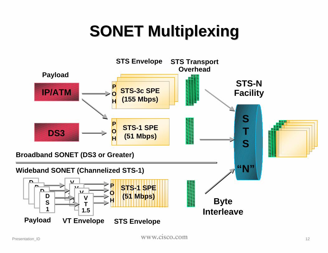
STS-1 SPE(51 Mbps)
STS-3c SPE(155 Mbps)
STS
“N”
Payload
STS Envelope STS TransportOverhead
STS-NFacility
Payload VT Envelope STS Envelope
Broadband SONET (DS3 or Greater)
Wideband SONET (Channelized STS-1)
ByteInterleave
IP/ATM
DS3
SONET MultiplexingSONET Multiplexing
POH
POH
POH
STS-1 SPE(51 Mbps)
VT
1.5VT
1.5VT
1.5VT
1.5
DS1
DS1
DS1
DS1

13Presentation_ID
One Sub-FramePer STS-1 Frame
A1 A2 C1A1 A2 C1
J1B3C2G1F2
Z3Z4Z5
H4
TOH(3 Byte/
Columns)
SOH(3 Byte/
Rows)
LOH(6 Rows)
STS- SPE (87 Byte/Columns)
STS- SPE (87 Byte/Columns)
STS POH(9 Rows)
InterleaveOrder
(125 µµS)
“N” STS-1Frames forSTS-N Signal
If STS SPEMapped
1 VT Subframeper Column
If DS3 MappedDS3 Fills SPE
More SONET MultiplexingMore SONET Multiplexing
DS3 (M13 or Clear
Channel)12
3
V-4V-4 RR SSV-3V-3 RR SS
V-2V-2 RR SSV-1V-1 V-5V-5 SS
DS1Payload
500 µµS375 µµS
250 µµS
VT 1.5Superframeand 500 mSVT 1.5 SPE
125 µµS
A1 A2 C1
F1
D3
H3
K2
D9
D12
E2
E1
D2
B1
D1
H2
K1
D8
D11
Z2
H1
B2
D7
D10
Z1
D6D5D4

14Presentation_ID
IP/ATM Mapping into SONETIP/ATM Mapping into SONET
• IP packets and ATM cells are mapped into SONETtoday !
• Packet/Cell octets aligned with SONET byteboundaries
• Cell/Packet boundaries can cross SONET STS-N frameboundaries
Frame n
J1B3C2G1F2
Z3Z4Z5
H4
FixedStuff
J1B3C2G1F2
Z3Z4Z5
H4
FixedStuff
Frame n+1
TOH TOH
A1A2 A1A2

15Presentation_ID
ADM orADM or DCS DCS
Line Line
LineTermination
PTEPTE(ADM,(ADM,
DSLAM,…DSLAM,…
PTEPTE(ADM,(ADM,
DSLAM,…DSLAM,…
Service (DS1, DS3…)Mapping Demapping
Path
Path Termination
PathTermination
Service (DS1, DS3…)Mapping
Demapping
Section Section Section Section
Section Termination
SectionTermination
REG REG
PTE = Path Terminating ElementMUX = Terminal MultiplexerREG = RegeneratorADM = Add/Drop MultiplexerDCS = Digital Cross-Connect System
SONET Overhead LayersSONET Overhead Layers

16Presentation_ID
SONET Overhead ByteSONET Overhead ByteDesignationsDesignations
Transport Overhead
FramingA1
FramingA2
Trace/ GrowthSTS ID J0/Z0
BIP-8B1
OrderwireE1
UserF1
D1 D2 D3
SectionOverhead
BIP-8B2
OrderwireE2
PointerH1
PointerH2
PointerH3
APSK1
APSK2
D4
D7 D8
D10 D11 D12
D9
D5 D6
Sync Status/Growth S1/Z1
REI/ GrowthM0 or M1/Z2
LineOverhead
Path Overhead
BIP-8B3
UserF2
TraceJ1
Signal LabelC2
Path StatusG1
IndicatorH4
GrowthZ3
GrowthZ4
TandemConnection Z5
Line Data Communication Channel
Section Data Communication Channel

17Presentation_ID
Framing BytesFraming Bytes
• 2 bytes for framing (F628)• reside in all STS-1s• framer typically searches for
A1/A2 boundary• set by h/w
POH
BIP-8B3
UserF2
TraceJ1
Signal LabelC2
Path StatusG1
IndicatorH4
GrowthZ3
GrowthZ4
TandemConnection
Z5
BIP-8B2
OrderwireE2
PointerH1
PointerH2
PointerH3
APSK1
APSK2
D4
D7 D8
D10 D11 D12
D9
D5 D6
SyncS1/Z1
REI M0 orM1/Z2
Line Data Comm. Channel
FramingA1
FramingA2
T/G STSID J0/Z0
BIP-8B1
OrderwireE1
UserF1
D1 D2 D3Section Data Comm. Channel
TOH
SOH
LOH

18Presentation_ID
Performance MonitoringPerformance Monitoring
• Separate checks for Section,Line and Path
• BIP = ‘Bit Interleaved Parity’• Simple ‘even parity’ scheme• Parity calculated over all
corresponding bit positions inprevious frame.
• set by h/w
• B1: 1 x BIP-8 byte / STS-N• B2: N x BIP-8 bytes / STS-N• B3: 1 x BIP-8 byte / SPE
• B1/B3 do not scale well with N!
POH
BIP-8B3
UserF2
TraceJ1
Signal LabelC2
Path StatusG1
IndicatorH4
GrowthZ3
GrowthZ4
TandemConnection
Z5
BIP-8B2
OrderwireE2
PointerH1
PointerH2
PointerH3
APSK1
APSK2
D4
D7 D8
D10 D11 D12
D9
D5 D6
SyncS1/Z1
REI M0 orM1/Z2
Line Data Comm. Channel
FramingA1
FramingA2
T/G STSID J0/Z0
BIP-8B1
OrderwireE1
UserF1
D1 D2 D3Section Data Comm. Channel
TOH
SOH
LOH

19Presentation_ID
A1 A2 C1F1D3H3K2
D9D12E2
E1D2
B1D1
H2K1
D8D11Z2
H1B2
D7D10Z1
D6D5D4
A1 A2 C1F1D3H3K2
D9D12E2
E1D2
B1D1
H2K1
D8D11Z2
H1B2
D7D10Z1
D6D5D4
1 2 3 4 5 6 7
B1 Byte
8
Even parity calculated over all bit 8s from previous STS-N frame.
Section BIP-8 (B1) ExampleSection BIP-8 (B1) Example
A1 A2 C1F1D3H3K2
D9D12E2
E1D2
B1D1
H2K1
D8D11Z2
H1B2
D7D10Z1
D6D5D4
A1 A2 C1F1D3H3K2
D9D12E2
E1D2
B1D1
H2K1
D8D11Z2
H1B2
D7D10Z1
D6D5D4
A1 A2 C1F1D3H3K2
D9D12E2
E1D2
B1D1
H2K1
D8D11Z2
H1B2
D7D10Z1
D6D5D4
A1 A2 C1F1D3H3K2
D9D12E2
E1D2
B1D1
H2K1
D8D11Z2
H1B2
D7D10Z1
D6D5D4
Frame n Frame n+1
Even parity calculated over all bit 1s from previous STS-N frame.

20Presentation_ID
1 2 3 4 5 6 7
B2 Byte
8
Even parity calculated over all bit 8s from previous STS-1 frame - LOH.
Line BIP-8 (B2) ExampleLine BIP-8 (B2) Example
H3K2
D9D12E2
H2K1
D8D11Z2
H1B2
D7D10Z1
D6D5D4
H3K2
D9D12E2
H2K1
D8D11Z2
H1B2
D7D10Z1
D6D5D4
Frame n Frame n+1
Even parity calculated over all bit 1s from previous STS-1 frame - LOH.

21Presentation_ID
Data Communication ChannelData Communication Channel(DCC)(DCC)
• Out-of-Band communicationschannel
• Used to transmit OAM datato/from Network Managementsystem
• Separate Section and Linechannels
• D1-D3 - 192 kb/s OSI/CMIP• D4-D12 - 576 kb/s OSI/CMIP
POH
BIP-8B3
UserF2
TraceJ1
Signal LabelC2
Path StatusG1
IndicatorH4
GrowthZ3
GrowthZ4
TandemConnection
Z5
BIP-8B2
OrderwireE2
PointerH1
PointerH2
PointerH3
APSK1
APSK2
D4
D7 D8
D10 D11 D12
D9
D5 D6
SyncS1/Z1
REI M0 orM1/Z2
Line Data Comm. Channel
FramingA1
FramingA2
T/G STSID J0/Z0
BIP-8B1
OrderwireE1
UserF1
D1 D2 D3Section Data Comm. Channel
TOH
SOH
LOH

22Presentation_ID
Automatic Protection SwitchingAutomatic Protection Switching(APS)(APS)
• K1/K2 - Automatic ProtectionSwitching (APS)
• Bit mapped communicationchannel between LTEs forcontrolling protection switching.
• Under control of APS s/w on linecard
• Used on P link only
POH
BIP-8B3
UserF2
TraceJ1
Signal LabelC2
Path StatusG1
IndicatorH4
GrowthZ3
GrowthZ4
TandemConnection
Z5
BIP-8B2
OrderwireE2
PointerH1
PointerH2
PointerH3
APSK1
APSK2
D4
D7 D8
D10 D11 D12
D9
D5 D6
SyncS1/Z1
REI M0 orM1/Z2
Line Data Comm. Channel
FramingA1
FramingA2
T/G STSID J0/Z0
BIP-8B1
OrderwireE1
UserF1
D1 D2 D3Section Data Comm. Channel
TOH
SOH
LOH
LTELTE
W
P
K1/K2 Channel

23Presentation_ID
Reverse signalingReverse signaling
POH
BIP-8B3
UserF2
TraceJ1
Signal LabelC2
Path StatusG1
IndicatorH4
GrowthZ3
GrowthZ4
TandemConnection
Z5
BIP-8B2
OrderwireE2
PointerH1
PointerH2
PointerH3
APSK1
APSK2
D4
D7 D8
D10 D11 D12
D9
D5 D6
SyncS1/Z1
REI M0 orM1/Z2
Line Data Comm. Channel
FramingA1
FramingA2
T/G STSID J0/Z0
BIP-8B1
OrderwireE1
UserF1
D1 D2 D3Section Data Comm. Channel
TOH
SOH
LOH
• LTE-LTE Signaling• Indicates to upstream LTE of
downstream failure.• RDI - Remote Defect Indicator
(hard failure - K2)• REI - Remote Error Indicator
(B2 bit errors - M1)
• set by h/w
LTELTE L FailL-RDI (k2)
B2 errorsL-REI (M1)

24Presentation_ID
Path TracePath Trace
• J1- Path Trace.• End-End path connectivity
check• 64 byte (SONET) or 16 byte
(SDH) repeating message.• Inserted continuously at
source, checked againstexpected value by receiver
• message typically set by user
• J0 - Section Trace. Notdefined yet (old STS ID byte)
POH
BIP-8B3
UserF2
TraceJ1
Signal LabelC2
Path StatusG1
IndicatorH4
GrowthZ3
GrowthZ4
TandemConnection
Z5
BIP-8B2
OrderwireE2
PointerH1
PointerH2
PointerH3
APSK1
APSK2
D4
D7 D8
D10 D11 D12
D9
D5 D6
SyncS1/Z1
REI M0 orM1/Z2
Line Data Comm. Channel
FramingA1
FramingA2
TraceJ0/Z0
BIP-8B1
OrderwireE1
UserF1
D1 D2 D3Section Data Comm. Channel
TOH
SOH
LOH

25Presentation_ID
Signal LabelSignal Label
• Describes contents of payload(e.g. DS1, ATM, FDDI etc.)
• fixed value, set by application
POH
BIP-8B3
UserF2
TraceJ1
Signal LabelC2
Path StatusG1
IndicatorH4
GrowthZ3
GrowthZ4
TandemConnection
Z5
BIP-8B2
OrderwireE2
PointerH1
PointerH2
PointerH3
APSK1
APSK2
D4
D7 D8
D10 D11 D12
D9
D5 D6
SyncS1/Z1
REI M0 orM1/Z2
Line Data Comm. Channel
FramingA1
FramingA2
TraceJ0/Z0
BIP-8B1
OrderwireE1
UserF1
D1 D2 D3Section Data Comm. Channel
TOH
SOH
LOH
1 2 3 4 5 6 7
C2 Byte
8
HEX VALUE PAYLOAD00 Unequipped01 Equipped – Nonspecific payload02 Virtual Tributaries04 DS312 139.264Mb/s13 ATM14 DQDB15 FDDI16 Scrambled POS (Proposed)CF Unscrambled POS

26Presentation_ID
Path StatusPath Status
• G1 Byte• Performs function of REI & RDI
for PTE
POH
BIP-8B3
UserF2
TraceJ1
Signal LabelC2
Path StatusG1
IndicatorH4
GrowthZ3
GrowthZ4
TandemConnection
Z5
BIP-8B2
OrderwireE2
PointerH1
PointerH2
PointerH3
APSK1
APSK2
D4
D7 D8
D10 D11 D12
D9
D5 D6
SyncS1/Z1
REI M0 orM1/Z2
Line Data Comm. Channel
FramingA1
FramingA2
TraceJ0/Z0
BIP-8B1
OrderwireE1
UserF1
D1 D2 D3Section Data Comm. Channel
TOH
SOH
LOH
1 2 3 4 5 6 7
G1 Byte
8
REI-P RDI-P UD
REI-P: G1 bits 1-4RDI-P: G1 bits 5-7Undefined: G1 bit 8

27Presentation_ID
Order wireOrder wire
• 64kbps voice channels• used for craftsperson
communication betweenequipment locations
• mobile phones commonly usedinstead
POH
BIP-8B3
UserF2
TraceJ1
Signal LabelC2
Path StatusG1
IndicatorH4
GrowthZ3
GrowthZ4
TandemConnection
Z5
BIP-8B2
OrderwireE2
PointerH1
PointerH2
PointerH3
APSK1
APSK2
D4
D7 D8
D10 D11 D12
D9
D5 D6
SyncS1/Z1
REI M0 orM1/Z2
Line Data Comm. Channel
FramingA1
FramingA2
TraceJ0/Z0
BIP-8B1
OrderwireE1
UserF1
D1 D2 D3Section Data Comm. Channel
TOH
SOH
LOH

28Presentation_ID
PointersPointers
• Payload Pointer bytes H1-H3• Align SPE within STS frame• set/controlled by h/w
POH
BIP-8B3
UserF2
TraceJ1
Signal LabelC2
Path StatusG1
IndicatorH4
GrowthZ3
GrowthZ4
TandemConnection
Z5
BIP-8B2
OrderwireE2
PointerH1
PointerH2
PointerH3
APSK1
APSK2
D4
D7 D8
D10 D11 D12
D9
D5 D6
SyncS1/Z1
REI M0 orM1/Z2
Line Data Comm. Channel
FramingA1
FramingA2
T/G STSID J0/Z0
BIP-8B1
OrderwireE1
UserF1
D1 D2 D3Section Data Comm. Channel
TOH
SOH
LOH

29Presentation_ID
Misc Misc BytesBytes
• F1: Customer communicationschannel. Not used much.
• F2: same as F1.• S1: Sync status byte. Indicates
synchronization quality of OC-N signal.
• H4: Multi-frame byte. Only usedfor VT payloads.
• Z3/4: Growth bytes. Allocatedfor future undefined uses.
• Z5: Tandem connection. Newfunction. Not used much.
POH
BIP-8B3
UserF2
TraceJ1
Signal LabelC2
Path StatusG1
IndicatorH4
GrowthZ3
GrowthZ4
TandemConnection
Z5
BIP-8B2
OrderwireE2
PointerH1
PointerH2
PointerH3
APSK1
APSK2
D4
D7 D8
D10 D11 D12
D9
D5 D6
SyncS1/Z1
REI M0 orM1/Z2
Line Data Comm. Channel
FramingA1
FramingA2
T/G STSID J0/Z0
BIP-8B1
OrderwireE1
UserF1
D1 D2 D3Section Data Comm. Channel
TOH
SOH
LOH

30Presentation_ID
OAM - The Big Picture ?OAM - The Big Picture ?
NetworkManagement LOS
LOFB1B2
ADM ADM ADM ADM ADM
1
2
3
K1/K2 K1/K2 K1/K2K1/K2
Three Steps:1) Detect failure (BIP-8, B1, B2, B3)2) Service restoration (50ms) - fast local signaling (K1/K2)3) Fault isolation and repair - signaling to centralized
network management location (DCC)
Data Communications Channel (DCC)

31Presentation_ID
MUX LTE LTE MUX
London Bristol
REG#1
REG#2
REG#N
4x140M 4x140M‘Supy’ Channel (SCM)
Is SONET the only way ?Is SONET the only way ?
• 565Mb/s Optical Line System
• Installed 1985, Mercury Communications,London-Bristol
• 5B6B Block Coded - 678Mb/s line rate
• Sophisticated single-ended OAM features
50kmOAM OAM
• LOS• Error counts• BER • Tx Laser Bias• Rx Optical power• ALS

32Presentation_ID
To Wrap Up !To Wrap Up !
• TDM multiplexing onto high capacity fibersystems.
• Standard bit rate, frame format, opticalspecifications to ensure multi-vendorinteroperability.
• Fast restoration (50ms) schemes for bothlinear (pt-pt) and ring topologies.
• Operations, Administration, Maintenance &Provisioning (OAM&P)
- provision connections - performance monitoring - detect/isolate failures

33Presentation_ID
SummarySummary
• SONET provides standardization,interoperability, and OAM
• SONET is complex to implement
• largely due to requirement to support legacy traffic
• SONET is widely deployed
• However, there is no magic about SONET

34Presentation_ID
AcronymsAcronyms
• ADM: Add-Drop Multiplex
• APS: Automatic Protection Switching
• BIP: Bit Interleaved Parity
• BITS: Building Integrated Timing Supply
• OC: Optical Carrier
• POH: Path Overhead
• POS: Packet Over SONET
• PTE: Path Terminating Entity
• SDH: Synchronous Digital Hierarchy
• SONET: Synchronous Optical Network
• SPE: Synchronous Payload Envelope
• STE: Section Terminating Entity
• STM: Synchronous Transport Module
• STS: Synchronous Transport Signal
• TOH: Transport Overhead
• VT: Virtual Tributary

35Presentation_ID
ReferencesReferences
• Telcordia (Bellcore) GR-253-CORE
• ANSI T1.105 and T1.106
• ITU-T G.707 and G.783
• SONET, Walter J. Goralski, McGraw-Hill Series onComputer Communications
• Broadband Networking, ATM, SDH, and SONET, MikeSexton, Andy Reid, Artech House
• www.sonet.com

36Presentation_ID
Backup MaterialBackup Material

37Presentation_ID
SONET STS-1 Pointers
9 Rows
Transport Overhead
9 Rows
STS-1 SPE
Start of STS-1 SPE
H1 H2 H3
125 us
250 us
H1 H2 H3
STS-1 Path Overhead
0 us

38Presentation_ID
Pointer Bytes (H1, H2) - Channelized
1 2 3 4 5 6 7 8 9 10 268 269 270
271 273
2430
H1 H1 H1 H2 H2 H2
1 2 3 87 89 90
810
H1 H2
•Consider STS-3 •3 STS-1 bit steams of 51.84 Mbps
Transport Overhead (TOH)
Path Overhead (POH)
SPE
STS-3
3 x STS-1's

39Presentation_ID
Pointer Bytes (H1, H2) - Concatenated (STS-Nc)
•Consider STS-3c (c = concatenated)•Single bit stream of 155.52 Mbps
1 2 3 4 5 6 7 8 9 10 268 269 270
271 273
2430
H1 c c H2 c cSTS-3c SONETFrame
Transport Overhead (TOH)
Path Overhead (POH)
STS-3c SPE

40Presentation_ID
Using Pointers to AccommodateUsing Pointers to AccommodateTiming Offsets/JitterTiming Offsets/Jitter
Positive Stuff Positive Stuff Negative Stuff Negative Stuff
Byte After H3 Ignored, Or H3 Holds Extra Byte To Shorten/Lengthen FrameByte After H3 Ignored, Or H3 Holds Extra Byte To Shorten/Lengthen FrameH1, H2 Values Indicate Changes - Maximum Every 4 FramesH1, H2 Values Indicate Changes - Maximum Every 4 FramesRequires Close (Not Exact - up to 300ppm offset) Clock SynchronizationRequires Close (Not Exact - up to 300ppm offset) Clock SynchronizationAmong ElementsAmong Elements

41Presentation_ID
SONET Multiplexing HierarchySONET Multiplexing Hierarchy
• STS-1 signals can be wideband or broadbandWideband = Channeled with VT 1.5s containing DS1sBroadband = High rate DS3 and concatenated STS-1s
• VT mapped STS-1s are designed for transport andswitching of sub-STS-1 rate payloads
• STS-1s can be concatenated to create higher speedpayloads
STS-3c, STS-12c, STS-48c, STS-192c (future)For data applications, etc..
• STS-1s are multiplexed together to create the transmittedpayload
STS-N = N multiplexed STS-1sCan intermix broadband and wideband STS-1s within STS-NsN is currently defined as 1, 3, 12, 48, 192….

42Presentation_ID
Automatic Protection Switching
•Uses K1 and K2 bytes of Line Overhead•Needs 2 or more fibers•Allows network to react to failed lines, interfaces, or poor signal quality•Can be provisioned for a 1:1 or 1:n facility•For 1:1 each working facility is backed up or protected•For 1:n one protection facility exists for n-working fibers
1 2 3 4 5 6 7 8 9 10 268 269 270
271 273
2430
H1 c c H2 c cSTS-3c SONETFrame
Transport Overhead (TOH)
Path Overhead (POH)
STS-3c SPE
K1 K2
Section
Line

43Presentation_ID
APS - Diagram
1:1 Protection
1:N Protection
Working facility
Protection facility
Protection facility
Working facility
ADM/Router ADM/Router

44Presentation_ID
Automatic Protection Switching - K1, K2
•APS - all bits of K1 + bits 1-5 or K2•K1 byte:
Switch priority - K1 bits 1-4
Channel requesting switch action - K1 bits 5-8
•K2 byte:
Carries the Line "Alarm Indication Signal" and
Line "Remote Defect Indicator"