SON in LTE - additional materials
29
LTE SON as a concept for NW automation LTE SON podejściem do automatyzacji działania sieci
-
Upload
is-wireless -
Category
Technology
-
view
1.436 -
download
5
description
Here are some additional materials from tutorial entitled 'SON in LTE' delivered during the event ‘Lunch with LTE’ in November 2013 in Warsaw, Poland. If you are interested in attending top in class LTE/LTE-Advanced courses, please have a look http://is-wirelesstraining.com/course-map-2 or contact us directly: [email protected].
Transcript of SON in LTE - additional materials
LTE SON as a concept for NW automation
LTE SON podejściem do automatyzacji działania sieci

Copyright by IS-Wireless. All rights reserved. www.is-wireless.com
LTE SON Outline
1. SON Introduction
2. Self-Configuration Algorithms (PCI, ANR)
3. Self-Optimization Algorithms (ICIC, ESM)
4. SON Coordinaton

Copyright by IS-Wireless. All rights reserved. www.is-wireless.com
SON Introduction

Copyright by IS-Wireless. All rights reserved. www.is-wireless.com
SON Introduction SON Concept – Drivers for SON
High performance required
• Growing number of BW hungry services
• Growing number of devices and change of device character (M2M)
Heterogeneous Network to be cooperatively managed
• Macro/Micro/Pico/Femto cells and Relays
Overlaying multiple networks for a single operator
• 2G/3G/LTE/WiFi
Higher operational frequencies
• Increase number of cells required / higher NW cost
Increasing complexity of networks
• Multitude / growing number of parameters with interdependencies
• Multitude of RRM algorithms working at different time scales
HO thresh PRB conf
TimeToTrig
Hysteresis
AC thresh
AC
PSched
LTE
GSM UMTS
WiFi Core
cdma
2000
Copyright by IS-Wireless. All rights reserved. www.is-wireless.com
OAM
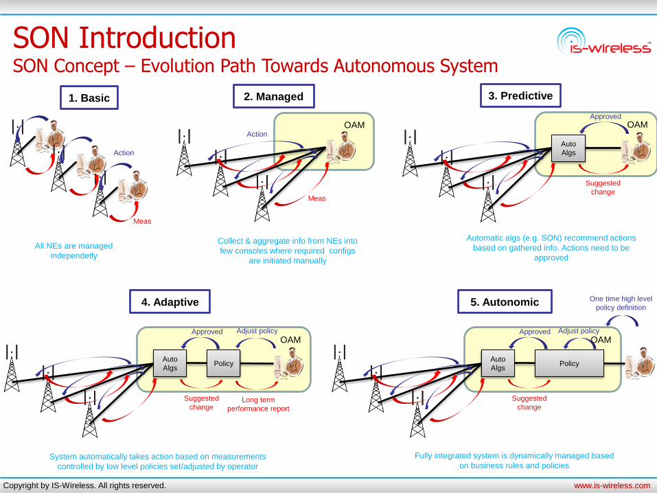
SON Introduction SON Concept – Evolution Path Towards Autonomous System
1. Basic
Meas
Action
2. Managed
Meas
Action
OAM
3. Predictive
Auto
Algs
Suggested
change
Approved
OAM
4. Adaptive
Auto
Algs
Suggested
change
Approved
Policy
Long term
performance report
Adjust policy
OAM
5. Autonomic
Auto
Algs
Suggested
change
Approved
Policy
Adjust policy
One time high level
policy definition
All NEs are managed
independetly
Collect & aggregate info from NEs into
few consoles where required configs
are initiated manually
Automatic algs (e.g. SON) recommend actions
based on gathered info. Actions need to be
approved
System automatically takes action based on measurements
controlled by low level policies set/adjusted by operator
Fully integrated system is dynamically managed based
on business rules and policies

Copyright by IS-Wireless. All rights reserved. www.is-wireless.com
SON Introduction SON Concept – Challenges for SON
”Although SON promises huge benefits towards having reliable and optimum mobile networks, the benefits come with challenges in making
them reality” M. Marvangi (ICIMU 2011, Malaysia)
Challenge SON Solution Requirement
Flexible SON configuration:
• Fully controlled SON
• Partly controlled SON
• Fully automatic SON
SON Cooperation /
SON Coordinator
Standardization Effort for
multi-vendor and coordination
Standardization Effort for
InterRAT SON
Convince operators to change NW management
• Redefinition of OAM/Planning/Optimization Procedures
• Gain trust on automation – gradual introduction of SON
Easy migration from non-SON to SON NW
Resolve conflicts between different SON functions
Assure that SON features taken from different vendors will
cooperate
Assure that SON solutions will operate in multi-RAT NW
• E.g. single tilt change for LTE optimization might influence
badly other RATs if single antenna used

Copyright by IS-Wireless. All rights reserved. www.is-wireless.com
SON Introduction SON Within 3GPP Standardization (1/2)
SON
Self Configuration Self Optimization Self Healing
3GPP approach for SON (3GPP TS 32.500):
”SON algorithms themselves will not be standarized in 3GPP”
”3GPP standarizes measurements, procedures and open interfaces to support SON”
eNB
Network
Plug in
Configuration
downloading
eNB
eNB
Optimize powers
HO params
PRACH params
eNB
eNB
restart
RF failure
Ala
rm
Recovery
actions
take
over UEs
SON: set of Use Cases that govern the NW including: planning, setup & maintanence
SON objective: minimization of manual changes of RAN configuration and optimization

Copyright by IS-Wireless. All rights reserved. www.is-wireless.com
SON Introduction SON Within 3GPP Standardization (2/2)
SON targets / policies
SON algorithms
Settings, parameters
Nodes and interfaces
eNB, UE measurements
SO
N F
ram
ew
ork
Standard / Operator
Non-standard / Vendor dependent
Standard
Standard
Standard
Non-standard / Operator
(counters / threshold / KPI)
Copyright by IS-Wireless. All rights reserved. www.is-wireless.com
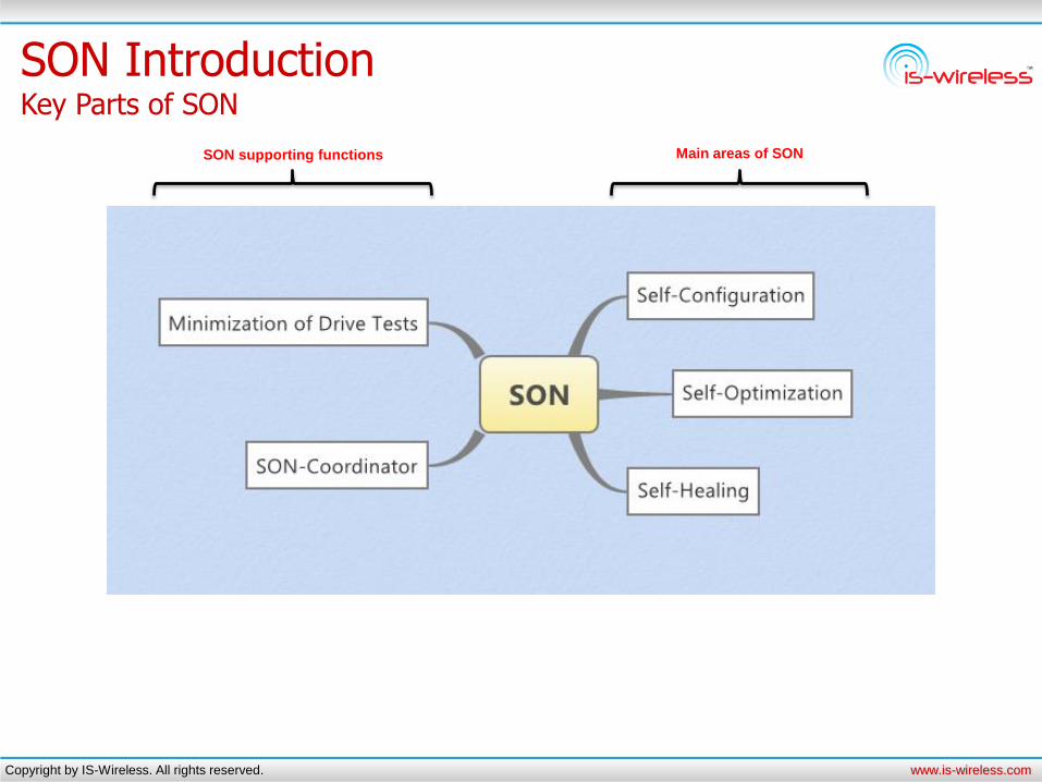
SON Introduction Key Parts of SON
Main areas of SON SON supporting functions
Copyright by IS-Wireless. All rights reserved. www.is-wireless.com
Self-Configuration
Copyright by IS-Wireless. All rights reserved. www.is-wireless.com
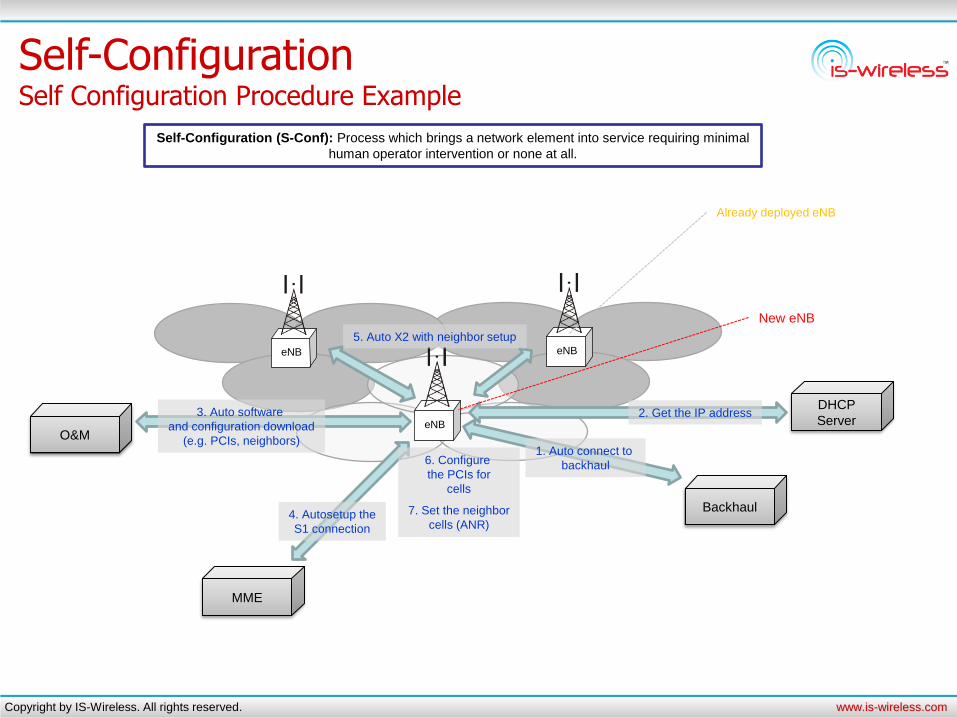
Self-Configuration Self Configuration Procedure Example
eNB
eNB
eNB
Backhaul
MME
DHCP
Server O&M
1. Auto connect to
backhaul
2. Get the IP address
4. Autosetup the
S1 connection
3. Auto software
and configuration download
(e.g. PCIs, neighbors)
5. Auto X2 with neighbor setup
6. Configure
the PCIs for
cells
7. Set the neighbor
cells (ANR)
New eNB
Already deployed eNB
Self-Configuration (S-Conf): Process which brings a network element into service requiring minimal
human operator intervention or none at all.
Copyright by IS-Wireless. All rights reserved. www.is-wireless.com
PCI = 6
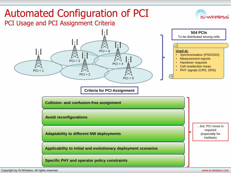
Automated Configuration of PCI PCI Usage and PCI Assignment Criteria
PCI = 1
PCI = 3
PCI = 2
PCI = 4
PCI = 5
504 PCIs To be distributed among cells
Used at:
• Synchronization (PSS/SSS)
• Measurement reports
• Handover requests
• Cell reselection meas.
• PHY signals (CRS, DRS)
Criteria for PCI Assignment
Collision- and confusion-free assignment
Avoid reconfigurations
Adaptability to different NW deployments
Applicability to initial and evolutionary deployment scenarios
Specific PHY and operator policy constraints
.. but, PCI reuse is
required
(especially for
HetNets)
Copyright by IS-Wireless. All rights reserved. www.is-wireless.com
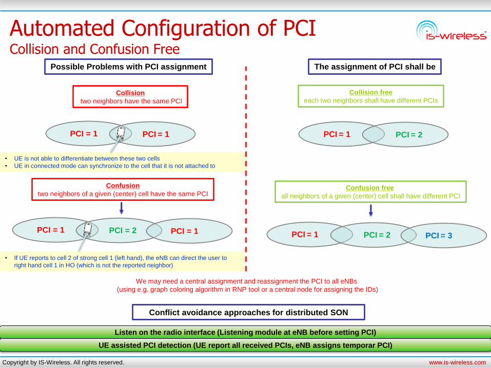
Automated Configuration of PCI Collision and Confusion Free
The assignment of PCI shall be
PCI = 1 PCI = 1
Possible Problems with PCI assignment
• UE is not able to differentiate between these two cells
• UE in connected mode can synchronize to the cell that it is not attached to
PCI = 1 PCI = 2
• If UE reports to cell 2 of strong cell 1 (left hand), the eNB can direct the user to
right hand cell 1 in HO (which is not the reported neighbor)
PCI = 1
Collision free
each two neighbors shall have different PCIs
PCI = 1 PCI = 2
PCI = 1 PCI = 2 PCI = 3
Confusion free
all neighbors of a given (center) cell shall have different PCI
Collision
two neighbors have the same PCI
Confusion
two neighbors of a given (center) cell have the same PCI
We may need a central assignment and reassignment the PCI to all eNBs
(using e.g. graph coloring algorithm in RNP tool or a central node for assigning the IDs)
Conflict avoidance approaches for distributed SON
Listen on the radio interface (Listening module at eNB before setting PCI)
UE assisted PCI detection (UE report all received PCIs, eNB assigns temporar PCI)

Copyright by IS-Wireless. All rights reserved. www.is-wireless.com
Automated Configuration of PCI Example Approach to Centralized PCI Assigment
Usage of Graph Coloring Approach • Use different colours for each node of the graph
• Use lowest number of different PCIs with collision / confussion free approach
1. Example network layout
2. Representation of the NW by graph • Node – cell
• Edge – neighborhood relation to direct neighbor or
neighbor of neighbor
Considered Cell
Direct neighbor
Neighbor of neighbor
4. Collision and confusion free PCI assignment
PCI B
PCI C
PCI A
PCI B
PCI C
Considered Cell
Neighbor of neighbor relation
Direct neighbor
relation
Approach: two connected nodes need to have different colours
3. Coloured Graph

Copyright by IS-Wireless. All rights reserved. www.is-wireless.com
Cell A
(serving)
Cell B
Cell C
Automatic Neighbor Relation Function Neighbor Relations Importance
NR Table
• Cell B
• Cell Z
No ANR
Measure Cell B
and report
Succesful HO
No Cell C
measurement
RLF and re-est
in cell C
Cell A
(serving)
Cell B
Cell C
NR Table
• Cell B
• Cell Z
With ANR
Measure Cell B
and report
Succesful HO
Cell C discovery /
measurement
and report Succesful HO
Cell C
NRT update and
HO control to cell C

Copyright by IS-Wireless. All rights reserved. www.is-wireless.com
Automatic Neighbor Relation Function UE Based LTE Cell Discovery (LTE ANR)
PCI 1 PCI 2
eNB
Core
NR Table
• PCI 10
• PCI 12
NR Table
• PCI 11
• PCI 13
• PCI = 1
• EGCI = 20 • PCI = 2
• EGCI = 30
PCI 2 PCI 1
7. New entry
(upd. NRT)
1. Measure signal (PCI = 2)
4. Read BCCH (ECGI = 30)
eNB
2. RRC Meas. Rep. (PCI = 2)
5. Report (ECGI = 30)
3. Request to report ECGI for PCI = 2
6. TNL address of
eNB with ECGI = 30
8. Establish X2 interface (X2 Setup)
9. New entry
(upd. NRT)

Copyright by IS-Wireless. All rights reserved. www.is-wireless.com
Self-Optimization

Copyright by IS-Wireless. All rights reserved. www.is-wireless.com
Self-Optimization Self Optimization Algorithm (High Level View)
Monitor input data
Analyse input data with
optimization algorithms
Execute corrective actions
One time self-optimization
procedure ends
Fallback
mechanism
Meet the
targets?
System state better after the
corrective actions execution?
Yes
No
Yes
No
Keep monitoring
Restore the system to
the previous state
(before the corrective
actions were executed)
UE measurements
UE signalling (e.g. RLF)
Cell global counters
Apply optimization
algorithm and
parameter adaptation

Copyright by IS-Wireless. All rights reserved. www.is-wireless.com
Inter-Cell Interference Coordination ICIC Scenarios
Downlink Uplink
Useful
signal Interference
eNB measures
interference UE measures interference and
sends info to eNB over
measurement reports
• Static – parameters are not changed (PFR or full reuse 1)
• Semi dynamic – slow adaptations of resources and CEU/CCU
threshold
• Dynamic ICIC scheme – frequent adjustments of parameters
(requires a lot of X2 signalling)
f
Power CEU
CCU
BW
Example semi-dynamic scheme – Partial Frequency Reuse
f
Power CEU
CCU
BW
Inner
zone Outer
zone
SON ICIC decides on: • Inner / outer zone threshold
• BW part for each zone
• Outer zone reuse scheme for neighbors
ICIC goal: Control the inter-cell interference (possible for PUSCH, PDSCH, PUCCH)

Copyright by IS-Wireless. All rights reserved. www.is-wireless.com
Inter-Cell Interference Coordination Example ICIC Operation on UE Mobility
1 2 3 4
5
Power
BW
f
Power
BW
f
Useful signal
Interference
1 2
3
4 5
UE is scheduled to inner subband
with low interference (due to large
pathloss) from cell 2
Cell 1 Cell 2
UE is scheduled to
outer subband where
cell 2 doesn’t transmit
UE is handed over from
cell 1 to cell 2
UE is scheduled to
outer subband where
cell 1 doesn’t transmit
UE is scheduled to inner subband
with low interference (due to large
pathloss) from cell 1

Copyright by IS-Wireless. All rights reserved. www.is-wireless.com
Inter-Cell Interference Coordination Proactive vs Reactive Approaches
Reactive approach Proactive approach (Dynamic PFR/SFR)
Using indicators of experienced interference
(interference is present)
Announcing scheduling decisions
(requires a lot of signalling)
eNB eNB
• HII = bitmap of UL PRB – interference sensitivity
• RNTP = bitmap of DL PRB – power threshold exceeding
I’ll schedule UE at
PRB x I’ll not use PRB x
eNB eNB
• OI = per UL PRB report on experienced interference
I’ve measured
interference at
PRB x
I’ll adapt power levels
of UEs to decrease
interference 1 2 1 2
Copyright by IS-Wireless. All rights reserved. www.is-wireless.com
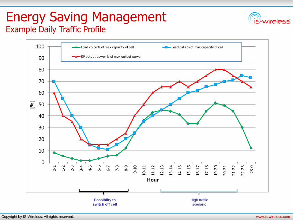
Energy Saving Management Example Daily Traffic Profile
0
10
20
30
40
50
60
70
80
90
100
0-1
1-2
2-3
3-4
4-5
5-6
6-7
7-8
8-9
9-10
10-1
1
11-1
2
12-1
3
13-1
4
14-1
5
15-1
6
16-1
7
17-1
8
19-2
0
20-2
1
21-2
2
22-2
3
23-0
[%]
Hour
Load voice % of max capacity of cell Load data % of max capacity of cell
RF output power % of max output power
Possiblity to
switch off cell
High traffic
scenario
Copyright by IS-Wireless. All rights reserved. www.is-wireless.com
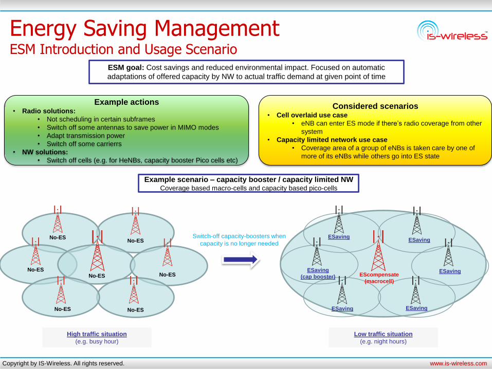
Energy Saving Management ESM Introduction and Usage Scenario
ESM goal: Cost savings and reduced environmental impact. Focused on automatic
adaptations of offered capacity by NW to actual traffic demand at given point of time
Example actions • Radio solutions:
• Not scheduling in certain subframes
• Switch off some antennas to save power in MIMO modes
• Adapt transmission power
• Switch off some carrierrs
• NW solutions:
• Switch off cells (e.g. for HeNBs, capacity booster Pico cells etc)
Example scenario – capacity booster / capacity limited NW Coverage based macro-cells and capacity based pico-cells
Switch-off capacity-boosters when
capacity is no longer needed
High traffic situation
(e.g. busy hour)
Low traffic situation
(e.g. night hours)
No-ES
No-ES
No-ES
No-ES No-ES
No-ES
No-ES
EScompensate
(macrocell)
ESaving
(cap booster)
ESaving ESaving
ESaving
ESaving ESaving
Considered scenarios • Cell overlaid use case
• eNB can enter ES mode if there’s radio coverage from other
system
• Capacity limited network use case
• Coverage area of a group of eNBs is taken care by one of
more of its eNBs while others go into ES state

Copyright by IS-Wireless. All rights reserved. www.is-wireless.com
SON Coordinator

Copyright by IS-Wireless. All rights reserved. www.is-wireless.com
Interaction Between SON Use Cases Problems with Interactions
UE
measurements
eNB
measurements
SON
Use Case 3
SON
Use Case 2
SON
Use Case 1
Parameter 1 Parameter 2
• Can alter the same parameter
• Interact with each other
• Can work against each other
• Performance depends on
multiple use cases
Multiple SON use cases
SON coordination definition (3GPP TS 32.522): ”SON Coordination means preventing or resolving conflicts or negative influences between SON functions to make SON functions comply with operator policy”

Copyright by IS-Wireless. All rights reserved. www.is-wireless.com
Interacting Use Cases - Example Interactions Between Handover Parameter Optimization and Load Balancing
SON algorithms Control parameters KPIs / metrics
Load balancing
HO param
optimization
HO offset
Hysteresis
TTT
HO failure
ratio
(HPIHOF)
HO ping
pong ratio
(HPIHPP)
RLF ratio
(HPIRLF)
Virtual
load
We
igh
ted
su
m:
HP
= w
1 *
HP
I HO
F +
w2
* H
PI H
PP +
w3
* H
PI R
LF
Metric conflict
Unsatisfied
users
Source: Socrates D5.9 Final report
Copyright by IS-Wireless. All rights reserved. www.is-wireless.com
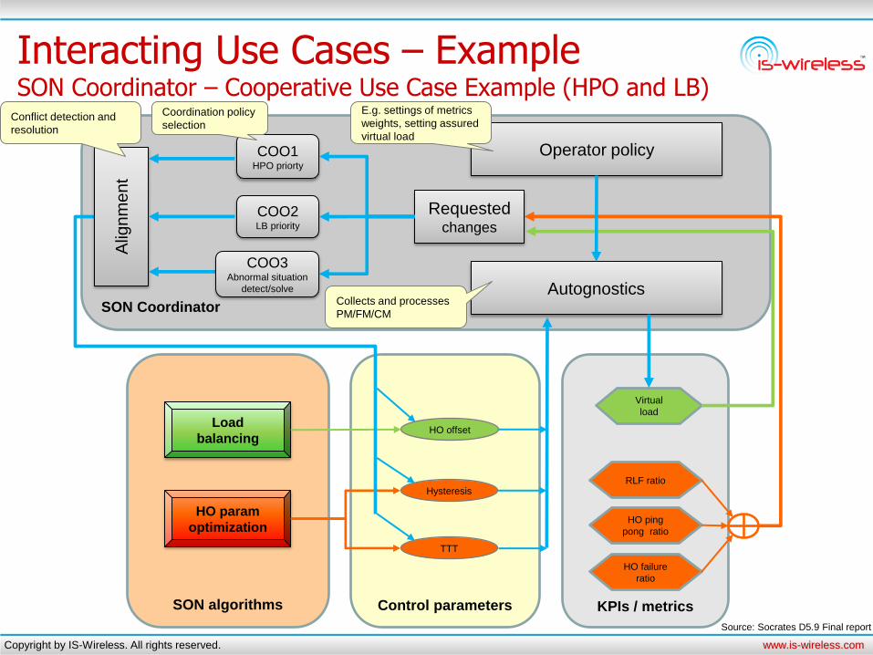
SON Coordinator
Interacting Use Cases – Example SON Coordinator – Cooperative Use Case Example (HPO and LB)
SON algorithms Control parameters KPIs / metrics
Load
balancing
HO param
optimization
HO offset
Hysteresis
TTT
HO failure
ratio
HO ping
pong ratio
RLF ratio
Virtual
load
Autognostics
Operator policy
Requested changes
Alig
nm
ent
COO1 HPO priorty
COO2 LB priority
COO3 Abnormal situation
detect/solve
Conflict detection and
resolution
E.g. settings of metrics
weights, setting assured
virtual load
Collects and processes
PM/FM/CM
Coordination policy
selection
Source: Socrates D5.9 Final report
Copyright by IS-Wireless. All rights reserved. www.is-wireless.com
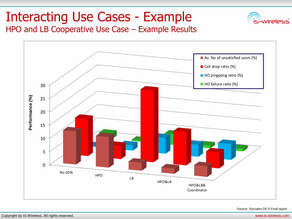
Interacting Use Cases - Example HPO and LB Cooperative Use Case – Example Results
0
5
10
15
20
25
30
No SONHPO
LBHPO&LB
HPO&LB&Coordinator
Av. No of unsatisfied users (%)
Call drop ratio (%)
HO pingpong ratio (%)
HO failure ratio (%)
Source: Socrates D5.9 Final report
Pe
rfo
rma
nce
(%
)
Copyright by IS-Wireless. All rights reserved. www.is-wireless.com
Thank you for your attention!


![Análisis de las prestaciones de los sistemas LTE y LTE ... · Ejemplo de ello son los simuladores ATOLL y Simu-LTE desarrollados por Forsk y OMNet++, respectivamente [4-5]. Sin embargo,](https://static.fdocuments.us/doc/165x107/5afc8dab7f8b9a8b4d8c545d/anlisis-de-las-prestaciones-de-los-sistemas-lte-y-lte-de-ello-son-los-simuladores.jpg)