Some failure studies in the Hooker extrusion of sintered iron powder metallurgical preforms
10
Journal of Mechanical Working Technology, 16(1988) 165-174 165 Elsevier Science Publishers B.V., Amsterdam -- Printed in The Netherlands SOME FAILURE STUDIES IN THE HOOKER EXTRUSION OF SINTERED IRON POWDER METALLURGICAL PREFORMS P. VENUGOPAL*, S. VENKATRAMAN**, R. VASUDEVAN* and K.A. PADMANABHAN* *Metallurgical Engineering Department, I.I.T., Madras (India) **General Technical Manager, M/S Heat Tech. Engineers, 112 Kamaraj Avenue, Adyar, Madras (India) (Received January 27, 1986; accepted in revised form March 18, 1987) Industrial Summary This paper highlights some typical circumferential and longitudinal cracking encountered dur- ing the Hooker extrusion of sintered iron preforms. Studies carried out indicate that the preform shape, the preform sintered density, the die included angle and the extrusion reduction {defor- mation ratio) have a strong influence in the arresting of such cracks. 1. Introduction The cold extrusion of sintered powder metallurgical (P/M) preforms is gaining a lot of importance in the manufacturing area due to well controlled tolerances and the versatility of the process. The successful cold forming of such preforms to a large extent depends upon the initial preform density, Po, the preform shape, the extrusion tool angle ( die included angle 2a in the pres- ent discussion) and the deformation ratio e [ 1 ]. The influence of these vari- ables on crack formation in cold extrudes of sintered iron preforms will be discussed herein. 1.1. P/M flow properties The flow properties of sintered preforms can be scrutinised on an a priori basis by examination of the basic flow expression, Y=Kae na where K. is the apparent strength coefficient (value of true flow stress Y at a true strain of unity ) and na is the apparent strain-hardening exponent. These quantities reflect the strain hardening and densification of the metal matrix and their values are normally determined by standard compression tests on suitably prepared P/M preforms. Large values of K, and low values of n, would be an indication that these preforms could be soundly deformed, [ 1,2 ]. Corn- 0378-3804/88/$03.50 © 1988 Elsevier Science Publishers B.V.
-
Upload
p-venugopal -
Category
Documents
-
view
214 -
download
0
Transcript of Some failure studies in the Hooker extrusion of sintered iron powder metallurgical preforms

Journal of Mechanical Working Technology, 16(1988) 165-174 165 Elsevier Science Publishers B.V., Amsterdam - - Printed in The Netherlands
SOME FAILURE S T U D I E S IN THE HOOKER E X T R U S I O N OF S I N T E R E D IRON POWDER METALLURGICAL P R E F O R M S
P. VENUGOPAL*, S. VENKATRAMAN**, R. VASUDEVAN* and K.A. PADMANABHAN*
*Metallurgical Engineering Department, I.I.T., Madras (India) **General Technical Manager, M/S Heat Tech. Engineers, 112 Kamaraj Avenue, Adyar, Madras (India)
(Received January 27, 1986; accepted in revised form March 18, 1987)
Industrial Summary
This paper highlights some typical circumferential and longitudinal cracking encountered dur- ing the Hooker extrusion of sintered iron preforms. Studies carried out indicate that the preform shape, the preform sintered density, the die included angle and the extrusion reduction {defor- mation ratio) have a strong influence in the arresting of such cracks.
1. Introduction
The cold extrusion of sintered powder metallurgical (P/M) preforms is gaining a lot of importance in the manufacturing area due to well controlled tolerances and the versatility of the process. The successful cold forming of such preforms to a large extent depends upon the initial preform density, Po, the preform shape, the extrusion tool angle ( die included angle 2a in the pres- ent discussion) and the deformation ratio e [ 1 ]. The influence of these vari- ables on crack formation in cold extrudes of sintered iron preforms will be discussed herein.
1.1. P / M flow properties The flow properties of sintered preforms can be scrutinised on an a priori
basis by examination of the basic flow expression,
Y=Kae na
where K. is the apparent strength coefficient (value of true flow stress Y at a true strain of unity ) and na is the apparent strain-hardening exponent. These quan t i t i e s ref lect the s t r a in h a r d e n i n g a n d dens i f i ca t ion of the m e t a l m a t r i x and the i r va lues are n o r m a l l y d e t e r m i n e d by s t a n d a r d c o m p r e s s i o n tes t s on su i t ab ly p r e p a r e d P / M p re fo rms . La rge va lues of K , a n d low va lues of n, would be an ind ica t ion t h a t t hese p r e f o r m s could be sound ly deformed, [ 1,2 ]. Corn-
0378-3804/88/$03.50 © 1988 Elsevier Science Publishers B.V.

166
pacts with lower values of n~ are closer to the equivalent wrought parts and, the residual porosity (voids) being minimal, could be predicted to have better ductility.
Due to the friction present during compaction, there can be non-uniform densification along the length of the compacts, this phenomenon being termed 'thinning'. An examination of thinning also affords a means of assessing the probablility of failure during cold extrusion. Prefbrms with greater thinning will crack during exit from the die under extrusion, because of the lack of den- sification and the impaired ductility. During cold extrusion, densification does take place. Such compacts which have a greater thinning effect will have a lower mean initial preform density and the level to which the density increases during extrusion in this case is less.
1.2. Friction effects in cold extrusion In general, deformation is assured in cold extrusion due to the prmclpm
stresses being compressive, [ 3 ]. The major source of' failure in cold extrusion is the high order of the tool stresses encountered, due to friction. The friction between the work-metal and the tool-metal interfaces causes differential ve- locities which can cause chevron failure. During deformation, due to the fric- tion in the die and container, the material in the outer regions is under a high degree of compression, whilst it is under relatively much less compresshm in the interior. When the deformed metal leaves the die land, the mode of the stresses changes and secondary tensile stresses arise that can cause surface cracks on the extrude.
P/M extrudes which are prone to inherent brittleness will easily fail under these moderate tensile stresses and thus the relevance of drawing attention to n a and to the thinning effect can be appreciated. These moderate secondary tensile stresses are chiefly responsible for the longitudinal and circumferential cracks in P/M extrudes.
A simple way to reconcile this situation would be to think in terms of tubri cation, but the expulsion of the lubricant during post-sintering may pose a problem. Thus a need arises to study the influence of forming variables such as the extrusion reduction e, the die included angle 2(~, and the preform design to avoid such cracking.
2. Objectives of the present work
Based on the concepts cited in the Introduction, an experimental pro~ gramme was evolved to prepare sintered iron preform compacts of different preform densities (5.9, 6.35, 6.6 g/cm 3 ). Slicing of these compacts was carried out to analyse the thinning effect and to determine the initial mean preform density. Standard ring-specimens were then prepared for compression ~ests to generate the data on Ka and n~,.

TABLE 1
Influence ofpo, ~ and ~ on circumferential cracking
167
a ( ° )
0.4 0.6 0.7 0.9 1.2
For a preform density of 5.9 g/cm 3 ~,pt X X X X X 45 X X X X - 60 X X X X -
For a preform density of 6.35 g/cm 3 aop t X X X X o.k. 45 X X (o.k) o.k. - 60 X X X X -
For a preform density of 6.6 g/em 3 ~. , t X X X X o.k. 45 X (o.k) o.k. o.k. - 60 X X o.k. o.k. -
X indicates severe circumferential cracking, (o.k) indicates slight circumferential cracks and o.k. indicates sound extrudes free from cracks (certified after magnaflux crack detection), o~,,pt was calculated using Lange's equation [3] for force estimation in Hooker extrusion. Based on least force requirement, aopt was found to be 23 °, 27 °, 29 ° and 36 ° for values of ~ of 0.6, 0.7, 0.9 and 1.2 respectively.
Hooker extrusion tooling was evolved with different extrusion reductions and different die included angles (details of the reduction and the angles are furnished in Table 1 ).
Cold Hooker extrusion of the preforms was then carried out to assess the conditions under which crack-free extrudes are possible.
3 . R e s u l t s a n d d i s c u s s i o n
Details of the iron powder used are available in Ref. [ 4 ]. Sintering of all the compacts (made under forces of 150, 250 and 350 kN; i.e. at compacting pres- sures of 283,472 and 660 N / m m 2) was carried out at 1140°C in an atmosphere of cracked ammonia.
On the preform Based on the results of ring-compression tests, the values of Ka and na of :he
compacts were evaluated, see Fig. 1. Condition 'a' appears to ensure the lowest value of na (of 0.27), which is very close to that for the equivalent wrought steel.
Reference to Fig. 2 indicates that the preforms corresponding to condition 'a' (compacted under a force of 350 kN) give a higher mean preform density

168
g- E E -; 300 >-
-~ 2 o o
6°° r Ring comp less lon
500tdQta Lub: Molykole
] 400 a
b
x
d
e o /
DETAILS
cu r ve o
curve b
curve C
c u r v e d
I O O L :urve e
01
i Init ial p re fo rm d e n s i t y , g / cm ~
6 '?5
6 %4
6 -46
6 "27 5 "82
I
0 2
Compac lion food Ik N)
350
350
250
250
150 i
03 04 T r u e s l r o m E
App. S l reng lh A p p . s l r a m i coel f KO hord .expo- ! N l m m 2 ! _ _ _ i nen t no "4
610 0 "27
562 0 2 8
556 0 29 i
" 5o~ o-3o i
_ _ J I . . J
0 5 06 07 O'B og
Fig. 1. Logarithmic plot of the flow curves of sintered iron compacts,
A compacted Qt 350 kN, mQx density vonahon over mean dens,ty:l 2°/o B- -do- 250kN, -- do :I-7% [ - -do- 150kN do ::67%
Smtered iron [ompo[t Shcmg done at 5 mm intervois
(dimn in mm)~. 45
7 0 . . . . . T O l s ~ " % 0 - - ~ . . . . . . . . ~'-
:¢ 55 i - ? , t x~ B
2, C
L_ i : i 0 5 10 15 20 25 30 35 40
01stonce !torn punch face !rnm~
Fig. 2 . Density variation along the length ( ' thinning' curves ).
( 6.6 g/cm:~: nearly 90% of the theoretical density) with least thinning effect (1.2%). These results are complementary to the indications afforded by the apparent strain-hardening exponent. It is to be expected that the preforms belonging to this category will have better ductility due to reduced residual porosity and therefore that forming should be easier.

169
3.2 The extrusion aspects The tooling evolved for the cold Hooker extrusion of the preforms is shown
in Fig. 3 whilst successful extrudes are presented in Fig. 4. The lubricant used was molybdenium disulphide paste.
3.2. I Preform design to avoid longitudinal cracks Initial trials conducted with cylindrical hollow preforms at different extru-
sion reductions and die angles, gave severe longitudinal cracks (Fig. 5) and circumferential cracks (Figs. 6-7). The reasons for the circumferential cracks were outlined in Secion 1.2. Table 1 lists the extrudes explored and illustrates the conditions under which cracks were encountered.
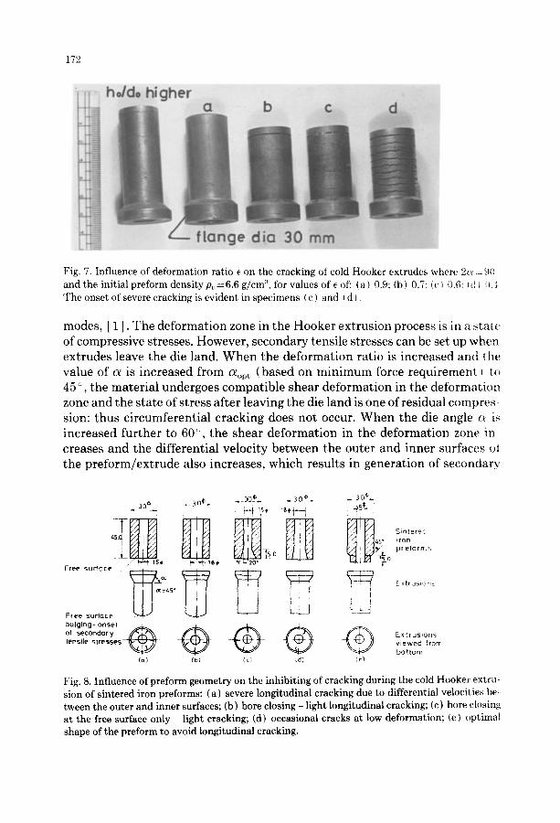
Longitudinal cracks (Fig. 5) persisted in all the preforms, including the category which had a low value of ha, a higher mean preform density and least thinning. The occurrence of moderate tensile stresses at the free surface (bulg- ing) due to friction constraints on the die, mandrel and preform interfaces was identified as responsible for such longitudinal cracks, see Fig. 8.
Reference to Fig. 8 illustrates the various options of preform design tried out to avoid longitudinal cracks. For all of the options from (a) to (d) deformation of the bottom surface was encountered, which lead to differential velocities in the wall of the extrudes, caused moderate secondary tensile stresses and re- sulted in longitudinal cracks. Option (e) established a most favourable con- dition, in that the free end (bottom face) was chamfered to suit the die bore, which would mean that this portion of the free surface would be pushed with- out any deformation during extrusion. Such a condition at the free surface resulted in the total avoidance of differential velocities in the wall and thus of the consequent cracks. However, the circumferential cracks at the free surface persisted: in actual production this problem could be overcome by the machin- ing off of this small portion. Option (e) would also minimise the time and difficulty involved in the machining of the preforms with respect to options (b), (c) and (d).
3.2.2 Circumferential cracking The initial mean preform density P0, extrusion ratio e and die included angle
have been observed to influence the formation of circumferential cracking: the reasons for such cracks have been discussed already. The following inferences can be made by reference to Table 1:
(i) For the same extrusion ratio e and die angle c~, an increase in the initial mean preform density lessens or even avoids circumferential cracking.
(ii) For the same preform density and die angle ~, circumferential cracking can be avoided by increasing the extrusion ratio.
(iii) Circumferential cracking was prevalent for all die angles and extrusion ratios up to 1.2 for P / M preforms compacted under 150 kN force ( compacting pressure 283 N / m m 2), having a mean preform density of 5.9 g/cm 3.

170
J
Fig. 3. Tool set for Hooker extrusion: A - load cell; B - p u n c h shoe; C - puch body; D Hooker
mandrel ; E - sh r ink r ing s u r m o u n t i n g the container ; F -- one of the die rings; G - mechanical
s t roke arrestors ; H - preform; I - cold extrude; J - press ram; K - press bed.
Fig. 4. S in tered iron p re fo rms cold extruded by the Hooker process.
( iv ) A minimum preform density of 6.25 g/cm 3 is required to avoid circum- ferential cracking.
(v) When the die angle is increased from a¢,pt to 45 °, circumferential crack-

1 7 1
~ - ~ ~
Fig. 5. Longitudinal cracking in cold extrudes made from the wrong preform shape.
= ii!
i :¸ ~ ! i ̧
....... ~iiii!!iii~ ~
~ 1̧11:̧2 !:i~ ̧
m m
Fig. 6. Circumferential cracking in cold Hooker extrudes produced with the wrong deformation ratio e, die angle a and preform density Po, resulting in violent thinning.
ing is l e s s ened and even avo ided for part icular va lues o f e and Po. Further in- crease in the die angle to 60 °, increases the degree o f c i rcumferent ia l cracking. T h i s is seen in the case o f 6.35 g / c m 3 and 6.6 g / c m 3 pre forms at die angles o f 45 ° and 60 ° for ex trus ion rat ios e o f 0.6, 0.7 and 0.9, from Table 1. T h e c o m p a c t s o f 6.35 g / c m 3 did n o t exhibi t any crack ing for c~--45 ° and e = 0.9. Very s l ight cracks were observed wi th e = 0.7. W h e n a was increased from 45 ° to 60 ° the extrudes exh ib i ted severe crack ing bo th for e = 0.7 and e = 0.9. T h e s a m e trend w a s observed for 6.6 g / c m 3 preforms.
H o o k e r ex trus ion w a s c h o s e n as the process for cold ex truding P / M c o m - pacts due to its favourable s tate o f s tress c o m p a r e d to the o ther co ld -ex trus ion
172
ho/do higher
, < :
b c d
2--- ficinge dici 30
Fig. 7. Influence of deformation ratio e on the cracking of cold Hooker extrudes where 2{~' : 90 and the initial preform density p~=6.6 g/cm:L for values of ( of: ( a ) 0.9: (b) 0.7: (c~ 0.6: (cii -,,~ The onset of severe cracking is evident in specimens ( c ) and ~ d },
modes, [ 1 ]. The deformation zone in the Hooker extrusion process is in a st:ate of compressive stresses. However, secondary tensile stresses can be set up when extrudes leave the die land. When the deformation ratio is increased and the value of ce is increased from c%t (based on minimum force requirement ) to 45 °, the material undergoes compatible shear deformation in the deformation zone and the state of stress after leaving the die land is one of residual compres- sion: thus circumferential cracking does not occur. When the die angle e~ is increased further to 60 ° , the shear deformation in the deformation zone in creases and the differential velocity between the outer and inner surfaces oi the preform/extrude also increases, which results in generation of secondary
_ 30¢_ -30 ©. - 30}-
& "' 45" iron _q[50 pr efo rrr:-~
. . . . .o o L I_A of secondary ~ Extrusions tensile stresses~'~ viewed from
bottom (a) (b) (c) (d) ¢,'}
Fig. 8. Influence of preform geometry on the inhibiting of cracking during the cold Hooker extru- sion of sintered iron preforms: (a) severe longitudinal cracking due to differential velocities b e tween the outer and inner surfaces; (b) bore closing - light longitudinal cracking; (c) bore closing at the free surface only - light cracking; (d) occasional cracks at low deformation; (e) optimal shape of the preform to avoid longitudinal cracking.
173
tensile stresses in the deformation zone, leading to circumferential cracks. A die included angle of 2~ = 90 ° is therefore more suitable and is the optimal angle for sound extrudes.
3.2.3 Cracking on the inner bore of the extrudes Cracks on the inner bore surfaces were also observed in some extrudes and
this was investigated. Due to the shape of the die taper, the flow of the material was throttled with respect to the surface of the straight inner bore of the ex- trude, where the flow of the extrude is unhindered. This causes a smaller ve- locity at the outer surface and a greater velocity at the inner surface or the extrude, which differential velocity is again responsible for the cracks emanat- ing from the inner bore.
The lubricant used in these tests was MoS2 paste, applied to both the outer and inner surfaces of the preform. Lubricant was also applied to the die bore and the mandrel surfaces. This situation lead to the cracks cited above. When the bore of the preform and mandrel surface were left unlubricated, these cracks totally disappeared. This obviously is due to the effects of friction in the inner bore matching those of the throttled flow at the outer of the deforming preform, the differential velocity thereby being avoided.
4. Conclusions
(1) The successful cold Hooker extrusion of sintered iron P/M preforms de- pends upon the appropriate combination of the important parameters, namely the initial preform density, the apparent strain-hardening expo- nent, the thinning, the extrusion ratio, the die angle, the preform shape and the frictional environment.
(2) A minimum preform density of 6.25 g/cm 3 is required in order to obtain successful (crack free) Hooker extrudes for e values of up to 0.9.
( 3 ) The optimal die angle ~ is found to be 45 ° and increasing the die angle (~ further to 60 ° increases the tendency to the occurrence of circumferential cracking.
(4) Longitudinal cracks in P/M extrudes can be avoided by choosing the cor- rect option in the preform design.
( 5 ) Cracks on the inner bore of P/M extrudes can be avoided by not employing lubrication between the mandrel and the inner surface of the preform.
(6) The basic approach for avoiding any type of cracks for a P/M material during deformation is to make use of any method which will avoid the generation of secondary tensile stresses and which will subject the material to compressive stresses only.

174
R e f e r e n c e s
1 S. Venkatraman, Studies on Cold Extrusion of Sintered Iron Preforms by the Hooker t'r~cess, M.S. Thesis, Dept. of Metallurgical Eng., I.I.T., Madras-600 036, India, Jan. 1987,.
2 H.A. Kuhn and C.L. Downey, Deformation characteristics and plasticity theory (~f ~mter~d powder materials, Int. J. Pow. Metall., 7 (1971) 15.
3 K. Lange, Text Book of Metal Forming, Vol. 2, Bulk Forming, Springer Verlag, Berlin. ~97i Chapter on Cold Extrusion.
4 P. Venugopal, S. Venkatraman, R. Vasudevan and K. A. Padmanabhan, Ring-compressum tests on sintered iron preforms, J. Mech. Work. Technol., 16 { 1988) 51-64.