SOME EXAMPLES OF ENERGETIC MATERIAL MODELLING WITH LSDYNA · SOME EXAMPLES OF ENERGETIC MATERIAL...
9
SOME EXAMPLES OF ENERGETIC MATERIAL MODELLING WITH LSDYNA Michel QUIDOT SNPE Propulsion – Centre de Recherches du Bouchet BP 2 – 91710 Vert –Le –Petit France Email : [email protected]
-
Upload
nguyenlien -
Category
Documents
-
view
235 -
download
1
Transcript of SOME EXAMPLES OF ENERGETIC MATERIAL MODELLING WITH LSDYNA · SOME EXAMPLES OF ENERGETIC MATERIAL...

SOME EXAMPLES OF ENERGETIC MATERIAL
MODELLING WITH LSDYNA
Michel QUIDOT
SNPE Propulsion – Centre de Recherches du Bouchet
BP 2 – 91710 Vert –Le –Petit France
Email : [email protected]
ABSTRACT :
SNPE is using DYNA codes for more 15 years for characterisation and modelling of energetic materials : high
explosives, solid propellants, gun propellants and pyrotechnic systems for functioning, safety, survivability
and vulnerability analysis in space and defence applications.
This paper presents some examples of the use of LSDYNA in the field of solid mechanics, fluid mechanics
and detonics.
The first example concerns the development of a constitutive model for a cast PBX. A general dynamic
viscoelastic model developed in LSDYNA is used to analyse Split Hopkinson Pressure Bar (adapted for soft
materials characterisation) experiments, reverse Taylor test instrumented by high speed framing camera and
VISAR system. A postprocessing variable implemented is used for analysing dynamic failure in dynamic
Brazilian tests performed with SHPB system.
Two others short examples are given : functioning of a pyrotechnic system separation in space application and
LSDYNA/Euler simulation of the interaction of blast waves with explosive charges in sympathetic detonation
phenomena.
MODELLING MECHANICAL BEHAVIOR OF PBX AT HIGH STRAIN RATE
Cast PBX (high explosives) are heterogeneous materials composed of a binder (a polymer such as HTPB) highly filled
with energetic crystalline charges (HMX, RDX, NTO, AP, Al, …). The general behaviour of this kind of materials is non-
linear viscoelastic.
Constitutive model
We have used a generalised Maxwell viscoelastic model with n components to represent the deviatoric mechanical
behaviour of cast HTPB PBX. This model was implemented in LSDYNA codes. For simplicity we use a Jaumann stress rate
and an integral form of viscoelasticity which lead to the following numerical scheme :
where sij is the deviatoric part of the stress tensor and ωij is the rotation tensor. The stress increment is given by :
and sij (t) is related to the deviatoric rate of deformation
The use of a Prony series for the shear modulus :
allows the calculation of the hereditary integral by recurrent formulas as often used in implicit codes. The
implementation in 3D needs 5 auxiliary variables by term by using the relation . The number of terms is not limited
but only 5 are currently used. The equation of state is purely elastic. A maximum effective strain based on a Jaumann rate :
has been added for post processing.
Experiments
Tensile static tests at different temperature and different strain rates and dynamic compression tests using Split
Hopkinson Pressure Bars (SHPB) have been performed [1]. Static tests are analysed with the time-temperature superposition
principle as described by Williams, Landel and Ferry [2] and values of the Young’s modulus are obtained in the time range
10-1 - 108 µs. A viscoelastic model is then derived in the time range of interest 0.1 – 10000 µs. SHPB experiments are
performed at room temperature and strain rate in the range 1000s-1 are achieved. Experimental stress are corrected and
transformed in true (Cauchy) stress assuming incompressibility of the material.
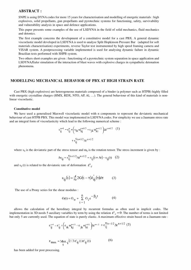
The reverse Taylor test with Visar measurement of the rear surface is used to investigate the mechanical response of the
viscoelastic material in a large continuum spectrum. Figure 1 shows the experimental arrangement.
The tests were conducted at a low impact velocity in order to concentrate on the viscoelastic behaviour of the material
before significant damage. Two tests were performed at 48 and 48.6 m/s impact velocities with well controlled impact
conditions (tilt less than three mrad). In the first shot, examination of the specimen after impact shows no damage and the
same dimensions as initial. The profile of the sample during impact shows a very small deformation and so the accuracy is
too weak to allow a quantitative information for comparison of models. The second shot was instrumented by VISAR.
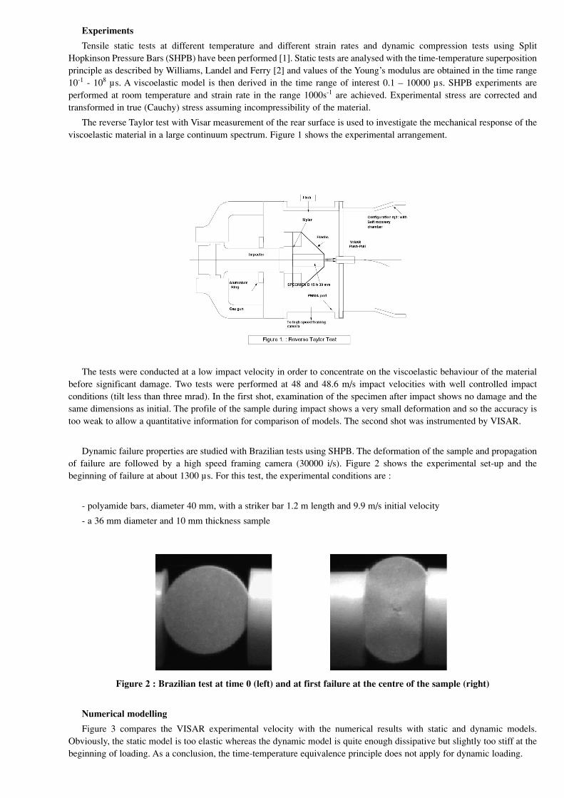
Dynamic failure properties are studied with Brazilian tests using SHPB. The deformation of the sample and propagation
of failure are followed by a high speed framing camera (30000 i/s). Figure 2 shows the experimental set-up and the
beginning of failure at about 1300 µs. For this test, the experimental conditions are :
- polyamide bars, diameter 40 mm, with a striker bar 1.2 m length and 9.9 m/s initial velocity
- a 36 mm diameter and 10 mm thickness sample
Figure 2 : Brazilian test at time 0 (left) and at first failure at the centre of the sample (right)
Numerical modelling
Figure 3 compares the VISAR experimental velocity with the numerical results with static and dynamic models.
Obviously, the static model is too elastic whereas the dynamic model is quite enough dissipative but slightly too stiff at the
beginning of loading. As a conclusion, the time-temperature equivalence principle does not apply for dynamic loading.

Figure 3 : Comparison of static and dynamic models on Reverse Taylor Test
In figure 4, the deformation of the sample during loading is shown, in a frame attached to the sample base, by comparison
to its original size. The observed small radial deformation is consistent with the high speed framing camera result. Fringes
of maximum effective strain (see equation 6) show that maximum level is achieved between 100 and 150 µs. This maximum
value of 25 % could indicate that non linear effects, not included in the viscoelastic model, exist.
Time : 50µs (left) and 100µs (right) Time : 150µs (left) and 200µs (right)
Time : 250µs (left) and 300µs (right) Level
.25
.20
.15
.10
.05
.00
Figure 4 : Maximum effective stress in Reverse Taylor Test
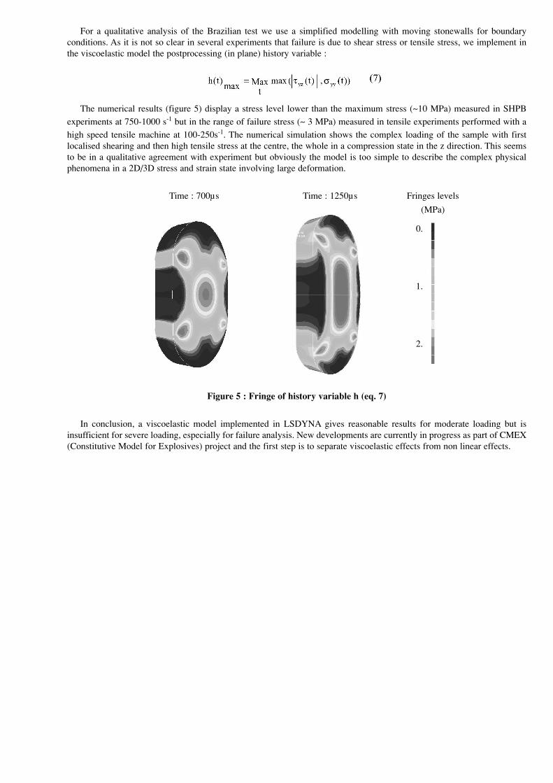
For a qualitative analysis of the Brazilian test we use a simplified modelling with moving stonewalls for boundary
conditions. As it is not so clear in several experiments that failure is due to shear stress or tensile stress, we implement in
the viscoelastic model the postprocessing (in plane) history variable :
The numerical results (figure 5) display a stress level lower than the maximum stress (~10 MPa) measured in SHPB
experiments at 750-1000 s-1 but in the range of failure stress (~ 3 MPa) measured in tensile experiments performed with a
high speed tensile machine at 100-250s-1. The numerical simulation shows the complex loading of the sample with first
localised shearing and then high tensile stress at the centre, the whole in a compression state in the z direction. This seems
to be in a qualitative agreement with experiment but obviously the model is too simple to describe the complex physical
phenomena in a 2D/3D stress and strain state involving large deformation.
Time : 700µs Time : 1250µs Fringes levels
(MPa)
0.
1.
2.
Figure 5 : Fringe of history variable h (eq. 7)
In conclusion, a viscoelastic model implemented in LSDYNA gives reasonable results for moderate loading but is
insufficient for severe loading, especially for failure analysis. New developments are currently in progress as part of CMEX
(Constitutive Model for Explosives) project and the first step is to separate viscoelastic effects from non linear effects.

MODELLING OF A PYROTECHNIC SYSTEM FOR SEPARATION
System studied
Pyrotechnic systems for separation are used in many space applications. A high reliability but also a low level of
generated shocks in the surrounding structures are required for these systems. A numerical and experimental study has been
conducted on a separation system by expanding tube for a possible optimization. This study has been supported by CNES
and presented at the first European conference on Launcher Technology [5].
The functioning of this system, representative of real devices, is described figure 6. The expanding tube contents a
stainless steel case, 1 mm thick, internal synthetic materials and a lead-RDX cord with 2g/m RDX charge.
Symmetrical separation Expanding
tube section
Figure 6 : Separation system
Numerical modelling
Balistic performance tests of the tube in free expansion were performed and the velocity of the minor axis (flattened form
of the tube) and of the major axis (cylindrical forms of the tube) were measured by a VISAR and a streak camera [3]
Numerical simulations in 2D of the free expansion of the tube show that the two principal components are the steel case
and the explosive. The elastoplastic model for the steel case is based on (static) tensile test. A first estimate of the JWL EOS
of RDX at density 1.55 g/cm3 is determined by a thermochemical code [4]. Comparison with literature data [6],[7] shows
that the detonation of the RDX charge is non ideal due the dimension of the explosive which is about the dimension of the
reactive zone of RDX. The JWL EOS was so recalibrated [3] by a simplified energetic method based on the experimental
measurements. A 3D calculation [5]demonstrates that there is no 3D effects. Figure 7 shows the good agreement between
2D and 3D calculations and experimental result. Figure 8 illustrates the functioning of the expanding tube.

Figure 7 : Velocity at the minor axis of the tube in free expansion Comparison of 2D and 3D simulations and experiment
Plastic strains at times 5,10 and 15 µs
Figure 8 : Expanding tube distorsions
BLAST WAVES AND SYMPATHETIC DETONATION MODELLING
LSDYNA/Euler capabilities (version 946) have been tested on sympathetic detonation phenomena : a donor charge is
detonated and the reaction of an acceptor charge by the blast wave generated is observed as a function of the distance
between donor and acceptor charges.
The simulation in 2D plane uses Euler, Lagrange and SALE formulations :
- the acceptor charge is Lagrangian
- the donor charge ( and part of surrounding air) is first Lagrangian (t=0. – 5.17µs), then ALE ( t=5.17µs – 6.17µs)
and finally Eulerian
- the air is Eulerian (Van Leer scheme)
The explosive is COMP B and is modeled with a Lee-Tarver reaction rate and JWL EOS for both reacted and unreacted
explosive determined by M. J. Murphy and all [8].
The reaction rate :
is function of compression rate (first term) and pressure (second term). The first term that represents the ignition is cut
off when the fraction reacted F reaches Figmax .

The JWL EOS relates pressure to specific volume and temperature :
The coefficients are summarized table 1.
Table 1 : Coefficients for the Lee-Tarver COMP B model
Figure 9 shows a non reaction of the acceptor for a one caliber distance between charges and figure 10 shows the
detonation of the acceptor for a half caliber distance between charges. These results are in agreement with experiments
performed at SNPE [9] and are encouraging for using new capabilities of LSDYNA/Euler
Time : 19µs Time : 27µs Pressure
Gpa
0.
.5
1.
Time : 34µs Time : 44µs
Figure 9 : Sympathetic Reaction – Donor/Acceptor distance : 1 caliber
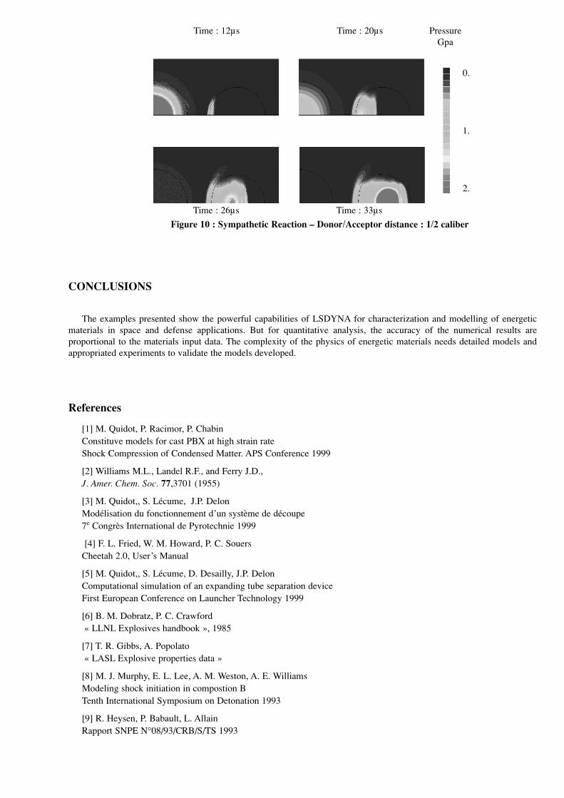
Time : 12µs Time : 20µs Pressure
Gpa
0.
1.
2.
Time : 26µs Time : 33µs
Figure 10 : Sympathetic Reaction – Donor/Acceptor distance : 1/2 caliber
CONCLUSIONS
The examples presented show the powerful capabilities of LSDYNA for characterization and modelling of energetic
materials in space and defense applications. But for quantitative analysis, the accuracy of the numerical results are
proportional to the materials input data. The complexity of the physics of energetic materials needs detailed models and
appropriated experiments to validate the models developed.
References
[1] M. Quidot, P. Racimor, P. Chabin
Constituve models for cast PBX at high strain rate
Shock Compression of Condensed Matter. APS Conference 1999
[2] Williams M.L., Landel R.F., and Ferry J.D.,
J. Amer. Chem. Soc. 77,3701 (1955)
[3] M. Quidot,, S. Lécume, J.P. Delon
Modélisation du fonctionnement d’un système de découpe
7e Congrès International de Pyrotechnie 1999
[4] F. L. Fried, W. M. Howard, P. C. Souers
Cheetah 2.0, User’s Manual
[5] M. Quidot,, S. Lécume, D. Desailly, J.P. Delon
Computational simulation of an expanding tube separation device
First European Conference on Launcher Technology 1999
[6] B. M. Dobratz, P. C. Crawford
« LLNL Explosives handbook », 1985
[7] T. R. Gibbs, A. Popolato
« LASL Explosive properties data »
[8] M. J. Murphy, E. L. Lee, A. M. Weston, A. E. Williams
Modeling shock initiation in compostion B
Tenth International Symposium on Detonation 1993
[9] R. Heysen, P. Babault, L. Allain
Rapport SNPE N°08/93/CRB/S/TS 1993