Some Early Internal Combustion Engines - Newcomen · PDF fileThe Piston Engine Revolution 177...
27
The Piston Engine Revolution 177 Some Early Internal Combustion Engines Bryan Lawton Newcomen Society This paper briefly describes seven of the earliest internal combustion engines. All the engines were demonstrated, but only those of Lenoir, and of Otto and Langen were commercially successful. Initially the availability of a suitable, inexpensive fuel was a great difficulty, but this was removed when coal gas was introduced into most towns for lighting. Brown’s atmospheric engine, in 1823-30, was the earliest to be used commercially. Wright abandoned atmospheric engines and used the pressure rise of the combustion products to drive a piston, and Gordon was the first to use this pressure to produce thrust to propel a boat. Barnett in 1838 introduced the important principle of compressing the mixture prior to combustion, and he was, therefore, the first to ignite a compressed mixture of fuel and air using a flame. Lenoir’s gas engine, adapted from existing steam engine technology, was the earliest reasonably successful engine, and the later Otto and Langen gas engine, 1867, succeeded because it was more efficient, if noisy. Neither Lenoir nor Otto and Langen used Barnett’s idea of pre-compression. KEYWORDS: Brown, Wright, Cayley, Gordon, Barnett, Lenoir, Otto and Langen. Introduction Power generation in the eighteenth century was dominated by steam, but despite Huygens’ work on a gunpowder engine the seventeenth century 1 it was not until the 1790s and later that inventors turned their minds towards other devices. Initially fuel was a great problem, for most early inventors not only had to invent an internal combustion machine, but also had to find or manufacture a suitable fuel. For example: Barber’s hot air engine, 2 patented in 1791, also anticipated the manufacture of gas by the distillation of coal. Street, in his 1794 patent 3 and Neipce, in his 1817 patent, 4 used turpentine or other essential oils, derived from plant products, as fuel. Cecil, 5 in his engine of 1820, and Brown, 6 in his 1823 engine, used hydrogen. Both Brown and Cayley used the hot products of coal combustion in their engines, but the adoption of coal gas for street lighting in the period 1820-50 eventually provided an appropriate, if expensive, fuel. However, ignition of the fuel-air mixture and the temperature reached by the combustion products caused problems not encountered in steam engines. This summary of
Transcript of Some Early Internal Combustion Engines - Newcomen · PDF fileThe Piston Engine Revolution 177...
The Piston Engine Revolution
177
Some Early Internal Combustion Engines Bryan Lawton Newcomen Society This paper briefly describes seven of the earliest internal combustion engines. All the engines were demonstrated, but only those of Lenoir, and of Otto and Langen were commercially successful. Initially the availability of a suitable, inexpensive fuel was a great difficulty, but this was removed when coal gas was introduced into most towns for lighting. Brown’s atmospheric engine, in 1823-30, was the earliest to be used commercially. Wright abandoned atmospheric engines and used the pressure rise of the combustion products to drive a piston, and Gordon was the first to use this pressure to produce thrust to propel a boat. Barnett in 1838 introduced the important principle of compressing the mixture prior to combustion, and he was, therefore, the first to ignite a compressed mixture of fuel and air using a flame. Lenoir’s gas engine, adapted from existing steam engine technology, was the earliest reasonably successful engine, and the later Otto and Langen gas engine, 1867, succeeded because it was more efficient, if noisy. Neither Lenoir nor Otto and Langen used Barnett’s idea of pre-compression. KEYWORDS: Brown, Wright, Cayley, Gordon, Barnett, Lenoir, Otto and Langen. Introduction Power generation in the eighteenth century was dominated by steam, but despite Huygens’ work on a gunpowder engine the seventeenth century1 it was not until the 1790s and later that inventors turned their minds towards other devices. Initially fuel was a great problem, for most early inventors not only had to invent an internal combustion machine, but also had to find or manufacture a suitable fuel. For example: Barber’s hot air engine,2 patented in 1791, also anticipated the manufacture of gas by the distillation of coal. Street, in his 1794 patent3 and Neipce, in his 1817 patent,4 used turpentine or other essential oils, derived from plant products, as fuel. Cecil,5 in his engine of 1820, and Brown,6 in his 1823 engine, used hydrogen. Both Brown and Cayley used the hot products of coal combustion in their engines, but the adoption of coal gas for street lighting in the period 1820-50 eventually provided an appropriate, if expensive, fuel. However, ignition of the fuel-air mixture and the temperature reached by the combustion products caused problems not encountered in steam engines. This summary of

The Piston Engine Revolution
178
seven of the earliest internal combustion engines reviews the progress that was made up to and including the introduction of Otto and Langen’s free piston engine in 1867. Brown’s Atmospheric Gas Engine, 1823. Brown’s pneumatic engine, Figure 1, bridges the old technology of waterwheels, the current technology of steam engines and the emerging technology of internal combustion. His engine had the advantage over a waterwheel in that it did not need a continuous supply from a river or stream and it could, therefore, be set up anywhere. Furthermore, it had the advantage over a steam engine that it was very quickly stopped or started and did not need a very large capital investment. According to the Mechanics’ Magazine (1824), the first model developed about 1.5 hp.7
The main idea was that hot combustion gases, from the combustion of hydrogen and air, filled cylinders FG and F’G’, were sealed in by the covers BC and B’C’, and were then cooled by water to produce a vacuum, which lifted water from the reservoir II’ to flow into the top of a waterwheel and thus produce power. The water from the bottom of the wheel was returned to the reservoir for re-use. Floats in the reservoir operated the various slide valves to control the transfer of gas, air, and water into the cylinders. The idea had several variants and it could be used for lifting water, for driving a waterwheel, or for driving pistons in a cylinder. Samuel Brown has the distinction of being the first person to put internal combustion engines into commercial operation and to have set up one or more companies for their production.
Samuel Brown came from humble beginnings or, as Bruce put it, “he did not command any substantial means”.8 Several patents were granted to him between 1811 and 1843. In his first patent (No. 3408, 1811), he describes himself as a cooper living in Norfolk Street, Southwark, and the patent is for machinery for the manufacture of casks. From this he seems to have made some money and moved to better premises. In his 1823 patent for his atmospheric gas engine he describes himself as “late of Windmill Street, Lambeth in the County of Surry, but now of Printing House Square, Blackfriars, in the City of London, Gentleman”; a rise from cooper to gentleman in only twelve years. According to his second gas engine patent (No 5350, 1826) he had moved again, this time to Eagle Lodge, Old Brompton. Eagle Lodge is now taken down but it was near the corner of Old Brompton Road and Gloucester Road, Kensington. He seems to have rented this house until about 1840, after which his work on gas engines diminished. He took out a further patent for the manufacture of tinned or zinc plated metallic casks, when living at 8, Finsbury Pavement, City of London, and later at Gravel Lane, Southwark; so he eventually returned to his original neighbourhood and to his original interests. He died in 1849 after a very active career developing and

The Piston Engine Revolution
179
Figure 1. Brown’s hydrogen fuelled gas engine lifts water to drive a waterwheel.
demonstrating numerous applications of his gas engine, most of which were reported in the Mechanics’ Magazine between the years 1823 and 1833.
Brown, in fact, specifies three designs in his patents, namely, one that turns a waterwheel, one that lifts water, and another that works pistons. The one turning a waterwheel, Figure 1, was the one he chose to demonstrate first to the Mechanics’ Magazine and it was the first to be described in the two patents

The Piston Engine Revolution
180
numbered above. But the future developments lay with the design that worked pistons. Both will be described. The main components in Figure 1 are as follows. A is a pivoted beam with circular ends, B and C are air-tight covers, connected to the beam by chains and rods through guides at J. D and E are two cylinders open at the top but air-tight when closed by the covers. F and G are two more cylinders, open at the top and closed at the bottom, placed within cylinders D and E but leaving a gap between them. There is a space between the upper ends of the inner and outer cylinders. H and H’ are non-return valves in the covers BC and B’C’. K, L M, are pipes connecting cylinders D and E. L is a clack valve. N and O are open cylinders. R indicates air-tight cylindrical floats in cylinders N and O. S is a pipe from cylinders D and E with a valve at Y. T indicates pipes from the reservoir of inflammable gas. At T’’’ is a cock to regulate the supply of gas to the cylinders. U is a trough to receive the water from pipes S through the valve V. W is a common, overshot waterwheel. X is a trough surrounding half the waterwheel, with an opening into the reservoir I. Pipes a, b are open to the air, over the ends of which a slide o moves. T, d, c indicate a pipe fitted with a cock and communicating with the burners, e, f. The latter are gas burners having jets f turned towards orifices h. The burners are perforated with a few small holes for the jets. The gas burner filled the inner cylinder F, G with combustion products and the cover B, C was lowered to form a seal. Combustion continued a short while and excess pressure was blown off to the atmosphere through a non-return valve H. The outside of the cylinder was filled with water that cooled the combustion products creating a vacuum and drawing water from the reservoir through the clack valve L and partially filling it. The vacuum produced was measured and found to be 24 to 25 inches of mercury, about 3 lb/in2 absolute, and was sufficient to lift water some 27 ft. When the vacuum was released the water was forced out into the reservoir U and onto the waterwheel. The Mechanics’ Magazine (1824) reported that eminent engineers had inspected the engine and acknowledged both its merits and its degree of perfection. They noted that “ - every day brings orders in great numbers, and from all parts of the country.” Brown’s engine could, of course, be used for lifting water, in which case the water wheel was removed. By 1832 a number of Brown’s engines were in use pumping water, the most notable being on the Croydon Canal.
According to Clerk Samuel Brown ought to be considered the Newcomen of the gas engine for although this engine was not a very great commercial success he was nevertheless the first to design and build an internal combustion engine and put it into everyday use.9 Comparison with Newcomen is apt because the principle on which his engine worked was similar to that of Newcomen’s atmospheric steam engine, and to Savery’s Miner’s Friend before that. In 1824 the Mechanics’ Magazine reported that a company had been formed to apply Brown’s gas engine to propelling a wheeled carriage and in 1826 they stated that Brown’s engine had

The Piston Engine Revolution
181
driven a road carriage that ascended Shooter’s Hill, Kent. In 1827, the magazine noted, “So long a period has elapsed – that the engine itself has almost gone from recollection, as one of the nine-day-wonders for which the public are periodically indebted to the office of Patents.” But in 1826 Brown had taken out a further patent for improved gas engine designs, one of which he used for road carriage and one for the propulsion of a boat that he demonstrated on the River Thames.
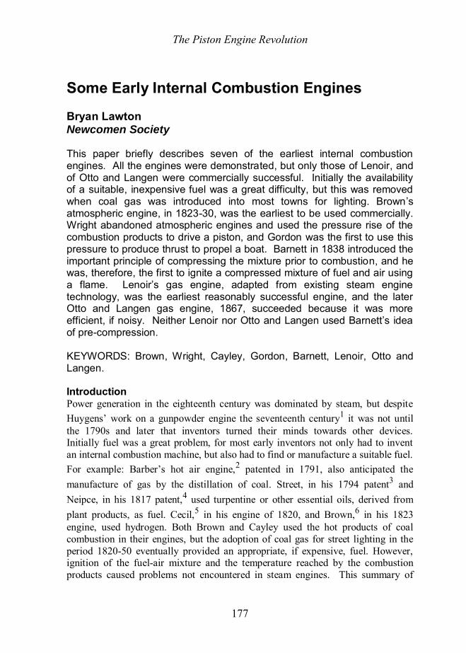
His 1826 piston-engine consisted of one or more large upright cylinders, Figure 2, fitted with a moveable lid covering the whole of each cylinder. The cover is raised or lowered onto its seat at appropriate time in the cycle by suitable valve gear. Initially a cylinder is filled with air and gas enters through a pipe fitted to the bottom of the cylinder. The gas cock is opened and ignited by a small flame and the hot products of combustion fill the open cylinder. Closing the cover and cooling the cylinder produced a partial vacuum. A separate, smaller cylinder fitted with a piston communicated with the large cylinder, through a valve or port. The vacuum allowed the atmospheric pressure above the piston to push it downwards and rotate a crankshaft. At the bottom of the stroke the small cylinder was opened to the atmosphere and it would fill with fresh air as it returned to its initial position. In this way several cycles of the small cylinder could be operated from the large cylinder before the vacuum became insufficient. The small cylinder was, in fact, a reciprocating steam engine running on a vacuum rather than steam pressure. In the meantime two other large cylinders were being prepared so there was always a vacuum available to drive one of the three cylinders and a continuous power output could be attained.
In 1827 the Mechanics’ Magazine reported that [another] company had been formed, during the rage for joint stock companies, for applying Brown’s invention to the propulsion of vessels on canals and rivers. However, this company also failed; details may be found in Bruce.10
Undeterred by two failures Samuel Brown set to work on a third venture, namely a gas vacuum engine for pumping water and fuelled not by hydrogen but by coal, one of which worked on the Croydon Canal and a second at Soham, Cambridgeshire, for drainage of the fens. This too was reported by the Mechanics’ Magazine (1832:273). They reminded their readers that the “only difficultly” was that, though a sufficient vacuum for working the engine could be obtained by the combustion of gas, the means were so expensive as to make the engine dearer than one worked by steam. However, they detailed the contents of three documents that claimed to have overcome this problem.
The first document was a circular dated 1 May 1832, announcing that Mr Brown was ready to contract for the construction of gas vacuum engines of any power and to guarantee their working for any number of years at half the expense of steam engines of the same power and in the same situation. He stated that four engines were already constructed and in successful operation
1. on the Croydon Canal for raising water from a lower to a higher level.
The Piston Engine Revolution
182
Figure 2. Samuel Brown’s gas engine, 1826, (after Clerk, 1906).
A, cover raised, vessel filling with flame, B and C, covers down, vessels vacuous. E gas cylinders, R framework, K gas supply pipe, T slide valve for gas admission, C cylinder
covers, I ignition valve, M gas admission valve, O piston cylinders, P side pipes for transferring vacuum and atmospheric air alternately above and below the piston using slide
valves Q, V main shaft with three cranks h
2. at Soham, Cambridgeshire, for the drainage of the Middle Fen District. 3. at Eagle Lodge, Old Brompton. 4. another at Eagle Lodge, but of a different construction than the preceding three, being one by which water may be raised from mines of any depth, and which may propel machinery of any sort.

The Piston Engine Revolution
183
The first three simply lifted water using the vacuum and released it at a modest height of about 12 feet. The fourth engine, presumably, was used to lift water to drive a waterwheel which could be used to operate force pumps at the bottom of a mine shaft by means of rods, as was quite normal at this time.
The second document contained copies of certificates from members of the committee of the Croydon Canal, and its superintendent, bearing testimony to the economy and efficiency of their gas engine. The editors of the Mechanics’ Magazine had seen this engine at work and reproduced the engraving shown in Figure 3. It consisted of a wrought iron cylinder, 22 feet high and 3 feet 6 inches in diameter, standing in the lower level of the canal, T. The cock B sets it to work and the wheel C regulates the motions and the speed. The valve D admits gas into the cylinder, is inflamed by a jet of lighted gas, E, and expels air from the cylinder by raising the lid F, which then shuts. The perforated tube G, fed from the pipe H, gives out its water and cools the cylinder gases instantly to complete the vacuum, which raises the water in the cylinder 7 feet above the discharge nozzle, I. The atmospheric valve, K, is then opened, and the water rushes out of the discharge valve I into the canal through the shoot L. The glass tube M indicates the height to which the water ascends. N is a pipe from the gasometer.
Figure 3. The Croydon Canal gas vacuum engine, 1832.

The Piston Engine Revolution
184
The third document was a paper describing the generation of the gas to work the engine. He says his first attention was given to making his engines perfect, and he had only lately experimented with making gas as cheaply as steam. It seems he made coal gas in the common way in closed retorts, but instead of heating them with coal, which represented a loss, he heated his retorts by coke ovens and all the coal in his retorts was converted to coke, tar and gas. He claimed that the profit from the sale of coke and tar would more than pay the expense of the coal used, and he gave an account of experiments with the Croydon gas apparatus, confirmed by an eminent engineer. He seems to have operated up to three retorts and claimed that 50 bushels of small coal produced 71 bushels of coke. He claimed a profit of £102 18s 0d per annum exclusive of what the work of the engine may be worth. In this he probably went too far and no doubt frightened off many people who would have supported more modest claims.
Clearly, for his engine to operate in places where there was no town gas supply, it was necessary to build retorts and manufacture the necessary gas. Such gas he claimed could burn directly in his engine without the expense of cleaning and purifying that was necessary for lighting purposes. For this he deserves much credit. As it was his claims were met with incredulity and, although he defended himself well enough in the letters to Mechanics’ Magazine, interest in his engine declined and then vanished. Wright’s Gas Engine, 1833.
Lemuel Wellman Wright, an engineer of London Road, Southwark, in his patent of 1833 described an explosive engine in which volumes of inflammable gases mixed with atmospheric air are ignited in a closed chamber.11 The resulting pressure rise acts on a piston in a cylinder in the same was as steam is usually applied for the purpose of producing power and driving machinery. Thus he abandoned the idea of an atmospheric gas engine relying on a vacuum, and instead he followed the idea adopted in high-pressure steam engines (see Figure 4). Wright is rather unspecific in describing the gas he uses and usually refers to it as “certain well known agents” or as “inflammable gas”. By 1823 some fifty-two English towns were lit by coal gas and by the date of Wright’s patent, 1833, coal gas was becoming established with gas works springing up in towns all over the country, so probably he took it for granted that coal gas was to be used.
A mixture of gas and air was supplied to the engine cylinder, B, from storage cylinders a and b, which were maintained at a slight pressure by separate compressors, c and d. An eccentric on the crankshaft drove the compressors. The gas and air were mixed in the valves h and the mixture ratio was controlled by the movement of a centrifugal governor, g. The mixture was admitted to the piston near to top-dead-centre and, being under a slight pressure, displaced the residual gases from the previous cycle. The spherical vessel W and the passage A

The Piston Engine Revolution
185
Figure 4. Wright’s gas engine, 1833.
constituted the combustion chamber. Gas supplied in the pipe Z maintained a continuous flame, which could be exposed by movement of a slide valve to ignite the mixture in the spherical vessel. At top-dead-centre the mixture was ignited and drove the piston towards bottom-dead-centre, transmitting the power to an output shaft by means of a crankshaft. At the end of the power stroke the exhaust valves at the end of the passage way marked A, were opened, and on the return stroke the exhaust gases were driven out into the exhaust pipe, G, by the rising piston. A reciprocating slide rod K operated the exhaust valves. As the piston nears top-dead-centre again the inlet valve opens and pressured mixture is admitted to the cylinder, driving out the residual mixture, and so the cycle is repeated.
The gaseous mixture admitted to the cylinder, it should be noted, is not compressed before it is ignited, except to a small degree by the external compressors, and so the cycle is not what came to be known as the two-stroke cycle. The expansion ratio, of course, was quite large. The engine was double acting so there were two power strokes per engine revolution; consequently the piston was exposed to hot combustion gases on two sides and would become too hot if left un-cooled. To counter this Wright supplied water down the central rod P to cool and lubricate the piston. Similarly the cylinder B has a very generous water jacket Q. Water-cooled pistons, even now, are very rare because of the trouble involved in their maintenance and thus if an engine was to be reliable, single acting

The Piston Engine Revolution
186
operation, and air-cooled or oil-cooled pistons would be preferred. Clerk, who was ultimately credited with the invention of the two-stroke cycle, was unable to discover whether Wright’s engine was ever manufactured, but as Clerk remarks, the detail given in the patent drawings suggest that the attempt was made.12 It seems that the engine was unsuccessful, and certainly the detailed design leaves much to be desired, but Wright deserves great credit for his work.
Sir George Cayley’s Hot Air Engine, 1837 Sir George Cayley (1773-1857) was born in Scarborough, Yorkshire and was the son of wealthy parents living at Brompton Hall and his education included mathematics, navigation and mechanics.13 In 1792 he inherited the baronetcy and was faced with the task of reviving the family’s estate. He developed and early interest in aeronautics, copying, in 1796, a toy helicopter invented by Lauoy and Bienvenu in 1784. This convinced him that a machine could be made to “rise in the air by mechanical means”. In 1799 he inscribed his ideas on a silver disc, now in the Science Museum, London. One side showed the forces on a wing resolved into lift and drag and, on the other side, was his idea for a fixed wing aeroplane. He tested possible aircraft wings using a rotating arm and measured the lift and drag of cambered aerofoil sections. In 1809 he successfully flew an unmanned, full-sized glider. He wished to attain manned flight but he realised that to do this he would need a suitable engine for his glider. Steam engines were too heavy, but he experimented with a gunpowder engine and, in 1807, with a hot-air engine.14 He did little in the next twenty years but he eventually turned his mind towards finding a suitable engine.
In 1837, Cayley applied the products of combustion from a closed furnace so that they would act directly on a piston in a closed cylinder. A pair of his engines is shown in Figure 5, which is based on a description of the engine in a paper by Poingdestre.15 An air pump, F, delivered compressed air through a pipe G to a closed vessel A containing a coal fire. The pressurised air supported the combustion of coal in the closed vessel and the exhaust products, at 600°F (315°C) were passed through a chamber, B, filled with wire mesh to separate any ashes or cinders, and from there into the working cylinder E that was fitted with a piston and valves very similar to a single acting steam engine. The hot, high-pressure combustion products were expanded in the cylinder thus producing power.
The engine was started by throwing (injecting) a few drops of water upon the closed fire, which evaporated and gave an impulse to the engine, causing the immediate action of the air pump, which then continued to work regularly and the engine continued to work. The fire was replenished by stopping the blast from the furnace and opening the upper bonnet. The cycle was, in fact, the same cycle of operations as the modern gas turbine, namely, compression, heating at constant

The Piston Engine Revolution
187
Figure 5. Sir George Cayley’s hot air engine, 1837.
A closed cylinder with furnace, B chambers (filter), C passages to working cylinders, D the valves, E working cylinder with pistons, F air pump, G passages for cold, compressed air,
H water injection pipes (onto the fire), J expansion gearing, L asbestos sights to inspect the fire, M oil pipes.
pressure followed by expansion. The main difference was that Cayley’s engine used a reciprocating compressor and a reciprocating expander, whereas modern gas turbines use rotary compressors and expanders (turbines). Had he but realised it, Sir George Cayley had, in this engine, the principle of the very engine he was seeking for his major interest, namely, manned flight in a heavier than air machine. Cayley’s hot air engine seems to have worked for a short time but it could not be made sufficiently reliable for commercial purposes. Poingdestre says that between them the two cylinders developed 8 hp when the piston travelled at 220 ft/min and he states that the high temperature was found to destroy the valves, piston, and cylinder and likewise to carbonise the lubricating oil. Hence there was great difficulty in keeping the working parts in order. It is likely that the dirty nature of the gas leaving the furnace was also a major problem. When gas engines were later developed to operate on the waste gas from blast furnaces it was found that cleaning the gas before it was passed to the engine was essential if the engine was to be reliable and easily maintained. Sir George was certainly aware of this problem but it seems that his filter in chamber B was not sufficiently good. Certainly, it did not have sufficient reliability to power an aeroplane. In the discussion to Poingdestre’s paper, Goldsworthy Gurney recalled that Cayley had carried out experiments in 1826, using two pairs of bellows. He then constructed an engine of about 1 hp, tested on a friction brake and by pumping

The Piston Engine Revolution
188
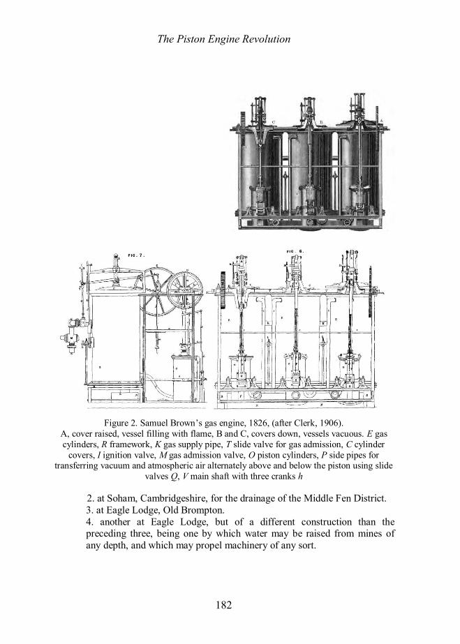
water, and it appeared that the fuel consumption was about two-thirds that of a steam engine of the same power. In the same discussion Gordon gave the fuel consumption as 6 lb of coal per hp hour, which corresponds to a rather modest thermal efficiency of about 3.1%. When the throttle valve was nine-tenths shut, and the piston travelled at 252 ft/min, 6 hp was obtained at a consumption of 5 lb/hp hour. Experiments were then made in London, on a larger scale, and raising the air to a higher temperature, but this was found to affect the working parts and injure the metal. The engine was subsequently taken to Sir George’s home in Yorkshire to remove these practical difficulties. It was thought that the invention promised eventually to become a valuable one. In one experiment a steam jet was substituted for the feed cylinder, when the air doubled in volume and came through the fire with great effect. On that occasion the heated air was made to act upon an apparatus on the principle of Barker’s mill (that is, using a jet to produce thrust), and the general results afforded great encouragement as to the ultimate success of the engine. Barnett’s Gas Engine, 1838 Perhaps the most interesting of the early gas engine designs is that of William Barnett which he patented in 1838.16 The third version of his engine is illustrated in Figure 6. It is, in many ways, similar to Wright’s engine of 1833 but more details are given. It is clear that a connecting rod and crank is used. A slightly pressurised gaseous mixture is admitted to both sides of the piston, that is, it is double acting, and ignition is by means of a flame when the piston is at the top (or bottom) of its stroke. The engine crankshaft drove, at twice engine speed, two independent single acting gas and air pumps and also an exhaust pump. The pumps fed the explosive mixture to the cylinder, and assisted in scavenging the exhaust gases of the previous stroke by driving them through a circular port halfway down the cylinder. The piston at half stroke uncovered this port to allow the gases to exhaust to atmosphere, thus reducing the expansion ratio and decreasing the effective portion of the stroke compared to later engines. When the cylinder falls below the inlet pipe pressure the inlet valve opens and the cylinder is re-charged. On the upward stroke the piston covered this port and compressed the charge in the cylinder. At top-dead-centre a flame from the ignition cock ignited the charge and drove the piston down the cylinder until the piston opened the exhaust port at mid-stroke. Thus Barnett’s engine patent anticipated the principle of operation of many later internal combustion engines.
There were three important innovations in Barnett’s engine. Firstly, he proposed to compress a gas and air mixture before igniting it. This may seem obvious now because compressing a gas to reach a high pressure and temperature is reversible whereas combustion is irreversible. Thus compression followed by combustion is more reversible and therefore more efficient than combustion alone. The second law of thermodynamics was not clearly understood in the early
The Piston Engine Revolution
189
Figure 6. William Barnett’s third gas engine of 1838 and the method of igniting a
compressed gas-air mixture. A is the piston, B is the air pump which hides the gas pump in the section.
nineteenth century and, indeed, many later gas engines, including the first successful gas engine, did not employ any degree of compression before ignition. Secondly, the method of ignition was novel and interesting because Barnett was faced with the prospect of igniting an explosive mixture in a state of compression. He proposed to use a cock with a hollow rotating plug, which contained a gas jet issuing from a nozzle (see Figure 6). When in one position, the plug sealed the engine cylinder and a flame beneath the plug ignited the jet. When the plug was rotated quickly a quarter of a turn the flame issuing from the nozzle was exposed to
The Piston Engine Revolution
190
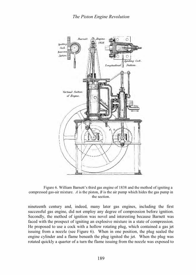
the main charge of gas and air in the cylinder and ignited it. When rotated back to its original position, the flame beneath the plug re-lighted the gas jet. It was a simple and ingenious system but Delamare-Deboutteville considered that although it was an important step it could not ensure a regular ignition.17 Thirdly, Barnett proposed to scavenge the exhaust gases from the cylinder using an exhaust pump, a system that subsequently became, and remains, common practice on two-stroke engines, although many modern engines rely on wave action in the exhaust pipe to create the necessary suction. Gordon’s “Fumific Impellor”, 1845-50 Gordon’s “Fumific Impellor” was a very simple means to propel a boat using hot gas from the combustion of coal to produce thrust.18 It was discussed by Poingdestre in his paper on Cayley’s engine and he says that Alexander Gordon, having seen Sir George Cayley’s engine when working at Millbank, and having also seen the engines of Stirling and Ericsson when working, determined to attempt the propulsion of a boat by the direct application of the products of combustion.19 These products, he said, rush out at the rate of 1,330 ft/s, and without the intervention of any machinery between the furnace and the water to be acted on by the hot blast. The figure of 1330 ft/s is quite reasonable because this is the speed of sound in a gas at a temperature of about 400°K, and this, of course, could be obtained in a choked flow when a gas at a gauge pressure of about 15 lb/in2 escapes through a hole. The bellows used here, however, was unlikely to attain such a pressure. Gordon’s engine is rather similar to Cayley’s but it is much simpler and instead of using a steam engine to expand the hot, high-pressure products of combustion, Gordon used a simple jet. Gordon, in fact, had invented a jet propulsion engine which is very similar to that used in modern jet aircraft (see Figure 7).
Figure 7. “The fumific impellor”, 1845, Gordon’s hot air engine propelling a boat.
A closed furnace, B bellows, C tailpipe

The Piston Engine Revolution
191
A bellows, operated manually, was used to blow air into a closed furnace to sustain combustion, and the exhaust gases were taken from the furnace in a simple tailpipe. The resulting thrust propelled the boat.
However, the thermal efficiency would have been very low, perhaps only one or two percent, because the pressure generated by the bellows was low. Consequently the coal consumption was high. Another disadvantage was that, because of the restricted air supply, the products of combustion were likely to contain large amounts of carbon monoxide, which is highly poisonous, and wasteful. Gordon’s own description of his propulsion unit and the results he obtained are brief enough to be quoted in full.
Into a boat, 26 ft long and 4½ ft broad, I fitted a close furnace, or retort, and a common small forge bellows [see Figure 7]. The close furnace being open at top and at bottom were then luted and fitted tight. The upper, or reservoir portion of the bellows was not used. Each stroke of the lower portion of the bellows passed air through the close fire, for the hot products of combustion to rush out against the water, as shown at C. The boat, when tried with this apparatus, weighed in all 4375 lb; in other words, that weight of water was displaced by her flotation when the discharge pipe C was immersed 12 inches. Each stroke of the portable forge bellows sent cold air into the close furnace. The appropriation of oxygen to support combustion was instantaneous; and the heating of all the aeriform body [gases], which passed off by C, was also instantaneous. The products of combustion, almost altogether aeriform, but also occasionally mixed with smoke, dust and ashes, rushed out (at a temperature of 800 or 900 degrees) by the pipe C, which was 3 inches in diameter. A valve being, of course, in the cold air pipe, between the bellows and the furnace I sent a succession of blasts into the bottom of the furnace, and consequently up through the intense fire, to find its way out under water by the pipe C. The first blast by one man always started the boat (weighing nearly 2 tons) from a state of rest, 3 feet in two seconds; and I believe that no two men with oars, with all the advantage of their flexor and extensor muscles, could do more. And neither paddle wheels, nor the Archimedean screw can start the same weight into such motion in the same time. I several times repeated these experiments upon what may be called the initial velocity had by the air first blast, or jet, or shot. The thrust obtainable, Gordon suggested, could be estimated from Borda’s
experiments where he showed that wind moving at 1 ft/s exerts a pressure of 1/500 lb/ft2. Therefore to find the thrust in lb/ft2 it was only necessary to divide the square of the velocity by 500. Although he did not calculate the value this formula suggests that the thrust obtainable from air at 1332 ft/s is 3548 lb/ft2, or 174 lb from a 3 inch bore pipe. Momentum thrust does increase as the square of velocity but the scaling factor (1/500) is incorrect; it should be the density.
The Piston Engine Revolution
192
Goldsworthy Gurney, as mentioned above, confirmed the results of Cayley’s experiments and was generally supportive of Gordon’s ideas, but eminent engineers such as I.K. Brunel and Robert Stephenson raised doubts. Brunel said his father, working for the celebrated Montgolfier, had tried the exact experiment in 1815 and it had been a failure. Stephenson thought that there was some discrepancy between the accepted theory and the actual expansive force of elastic fluids under the influence of high temperatures. He thought temperatures of 480°F (250°C) must be employed, which was too high for any material they had to deal with. Gordon defended his ideas very well. He said Brunel’s experiments did not bear on the present question because in those experiments the gases were compressed to their liquid state and were used somewhat as water was used, and not at all in the manner of Ericsson, Stein, Stirling or Sir George Cayley. He repudiated Stephenson’s statement that there was some discrepancy in the theory. And there the matter rested. Gordon’s engine, like Cayley’s, but unlike Stirling’s or Ericsson’s, was an internal combustion engine and was an important, if overlooked, step in the right direction. It was the future, but it was not the immediate future. Lenoir, 1860 The real breakthrough came in 1860 when Etienne Lenoir (1822-1900) in France produced the first commercially successful gas engine. Lenoir was born in Belgium but was naturalized French in 1870. He was primarily interested in electrical systems and is equally famous in electroplating and railway telegraphy. John Henry Johnson of London and Glasgow patented the engine in England on Lenoir’s behalf.20
In construction Lenoir’s engine was similar to a horizontal steam engine, which, perhaps, was one of its strengths, for he was adapting existing technology (Figure 8). Air and town gas, rather than steam, was admitted to a reciprocating piston in a cylinder through a pair of slide valves, one each side of the cylinder, which were driven from the crankshaft by an eccentric. They were not in pressurised steam boxes, as with ordinary steam slide valves, so springs and screws were used to hold the slides against the valve faces. The engine was double acting and one slide valve supplied air and gas to each side of the piston at the appropriate time. The other slide valve exhausted the combustion products from the two sides of the piston.
In operation a charge of ordinary lighting gas and air at atmospheric pressure was drawn into the cylinder until, at about half stroke, the ports closed and a spark ignited the charge, increasing the pressure by about 50 lb/in2. The pressurized combustion products drove the piston for the remainder of the stroke and thus the power stroke was only half of the working stroke. On the return stroke the products

The Piston Engine Revolution
193
Figure 8. Lenoir’s gas engine, 1860. A cylinder with water jacket, T slide valves, a air and gas ports, b exhaust ports, r gas cocks, C bearings, p piston, B crankshaft, C’ connecting rod, D eccentrics,
E pulley, G igniters, H distributor, L non-conducting ring, M metal segments, N conducting wire, V flywheel, F drive pulley.
of combustion were exhausted through the second slide valve, which closed at top-dead-centre, and the engine was ready for another cycle. An indicator diagram is shown in Figure 9.
The piston, it will be noted, did not compress the gas and air mixture before ignition. The ignition spark was generated using a system of Bunsen cells

The Piston Engine Revolution
194
and an induction coil, and the igniters were located in the end covers. As can be seen in Figure 9, the driving pressure varies from 57 lb/in2 after the explosion, to zero at the end of the stroke, the average pressure being 13.5 lb/in2 during the time of action, or a mean pressure of about 7 lb/in2 throughout the entire stroke. The engine ran at about 146 explosions per minute (73 rev/min). The low expansion ratio, about 2:1, produced a high gas-consumption of about 100 ft3/bhp hour. If the calorific value of the gas was 500 Btu/ft3, which is typical of coal gas, then the thermal efficiency was 5.1%. This was comparable to the thermal efficiency of a small reciprocating steam engine that was not fitted with a condenser.
Figure 9. Indicator diagram for Lenoir’s engine. The oscillations, shown dotted, are
caused by the vibration of the spring used in the pressure indicator and need to be smoothed out, as shown.
One of the disadvantages of the engine was that the piston could become
overheated due to the explosions that occurred on both sides. Consequently the cylinder was water-cooled, as shown in Figure 8, but this was insufficient to cool the piston as power (speed) increased. Steam engine pistons could not get hotter than the steam and thus it was possible to lag the cylinder to prevent heat loss without overheating the piston. A fundamental difference between steam engines and gas engines was that gas engine cylinders had to be cooled, and even then the piston could overheat unless power was restricted. Also, the piston rod was surrounded by hot gas for much of the time and became very hot.

The Piston Engine Revolution
195
Lenoir’s method of ignition was very attractive, in principle, and was often copied, but it had serious defects and eventually gas engine designers abandoned electrical ignition in favour of flame ignition and then, for a period, hot tube ignition. Ultimately, of course, electrical ignition became the norm. In Lenoir’s system, an insulator containing a platinum wire was fixed to each end of the cylinder and another platinum wire was fixed inside the cylinder with its tip a short distance from the first.
These wires were connected to the positive and negative poles of a Ruhmkorff coil (the old name for an induction coil) that was supplied by a battery of Bunsen cells. When a key completed the circuit at the proper moment, the iron core was magnetised and when the circuit was broken a spark passed across the tips of the platinum wires and the mixture was fired. As there were two combustion chambers and thus two igniters, G, it was necessary for Lenoir to devise a distributor to transmit the spark alternately to each. This he did by means of a rubber, gutta-percha, or other non-conducting collar on the crankshaft. This collar contained two metal segments, M, connected to a slip ring that was in constant contact with the current supply wire N. As the collar rotated the supply wire N was alternately connected, at the appropriate moment, through the two segments and to the igniters G in the cylinders.
The disadvantages of this ignition system are that vapour may condense on the platinum tips, wetting them, so the spark passes only occasionally or not at all. Also, when they are running, the tips often become coated with lubricating oil or with carbon deposits, and the spark is again prevented. These are problems that can still occur but are now mostly overcome. Another problem was that the current could jump the gap between the key and the contact plate even when the gap was as much as 0.75 inches wide, and it was very irregular in its timing. Delamare-Deboutteville notes that even a variation of one twentieth of a second makes a big difference to the power.21 At 180 rev/min such a delay corresponds to a crank rotation of 54 degrees so it is very significant.
Air and fuel were admitted through separate valves and by delaying the opening of the fuel valve, thus inducing pure air for a short time, Lenoir claimed to neutralise the effect of the carbonic acid (carbon dioxide) from the previous cycle that he thought might prevent the ignition of the inflammable gas. He was also concerned that the cylinders be properly cooled and he proposed that the heated water or steam leaving the cylinder should be stored for re-use. Lenoir claimed five novel and original inventions:
1. The general construction of machinery for obtaining motive power by the aid of inflammable gas and atmospheric air. 2. The use of electricity for igniting inflammable gas or vapour. 3. The use of solid or liquid hydrocarbons converted to a vapour to heat air in the cylinders of motive power engine
The Piston Engine Revolution
196
4. The use of electrical igniters in the cylinder of a motive power engine. 5. The use of a director (distributor) of the electrical current to bring the spark to bear at the proper time and place in a motive power engine.
His main claims relate to the invention and use of electrical ignition and distribution. Clerk, however, was not impressed by the novelty of the engine itself and thought that nothing was done that had not been proposed before.22 However, Lenoir’s engine was carefully thought out and was the first to emerge from the purely experimental stage. Clerk thought that Lenoir’s real credit consists in overcoming the practical difficulties sufficiently to make previous proposals workable, and for this he deserves the honourable place as the inventor of the first gas engine actually introduced to public use.
M. Hippolyte Marinoni constructed Lenoir’s engine in Paris in 1860. Two engines were manufactured in that year; one of 6 hp and one of 20 hp, and the gas consumption was shown to be about 3 m3/hp hour (106 ft3/hp hour), which corresponds to a thermal efficiency of about 4.8%. The action was said to be exceedingly smooth and no shock whatever was heard from the explosion. It was, in this respect, comparable to steam engines. In August 1865 the Practical Mechanics Journal reported that since its introduction between 300 and 400 engines were at work in France, the power ranging from 0.5 hp to 3 hp. Manufacture in Britain was undertaken by The Reading Iron Works Co Ltd at Reading and one hundred engines were made and delivered by them. They were used in printing, pumping water, driving lathes, cutting chaff, sawing stone, polishing marble, and, in fact, wherever 3 hp was sufficient. The inventors of engines often had erroneous ideas about how their inventions worked, and Clerk, having the benefit of a certain amount of hindsight, was able to correct these ideas in his book. Clerk notes that Lenoir erroneously supposed that greater economy could be obtained if he could use a slower explosion. Thus Lenoir experimented with charge stratification and the injection of steam or water spray because the “object of preventing the admixture of air and gas is to avoid explosion.” Rapid explosions were thought, erroneously, to be ineffective in transmitting work to the piston. The true nature of the poor thermal efficiency of Lenoir’s engine was explained in a paper presented to the “The Society of German Engineers” by Gustav Schmidt in 1861. “The results would be far more favourable if compression pumps, worked from the engine, compresses the cold air and cold gas to three atmospheres before entrance to the cylinder; by this a greater expansion and transformation of heat [into work] is possible.” The idea of pre-compressing the mixture before ignition was, apparently, discovered independently by several engineers at this time, and presumably without them being aware of Barnett’s engine or his patent of 1838 in which the gas was compressed before ignition.
The Piston Engine Revolution
197
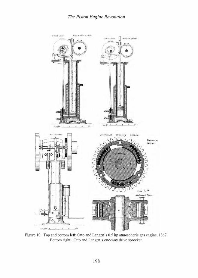
Otto and Langen, 1867 In 1867 Otto and Langen exhibited their free piston engine at the Paris Exhibition. Otto and Langen’s patent23 was taken out in Britain by their patent agent Charles Denton Abel and was first described, in English, by Crossley.24 The great improvement in the fuel consumption of their gas engine did not come, as might be expected, from pre-compression of the mixture before ignition but simply from an increased in expansion ratio. By using Barsanti and Matteucci’s free-piston idea Otto and Langen were able to attain the maximum possible expansion ratio, given the combustion pressure rise and the atmospheric pressure.25 Crossley Brothers of Manchester obtained the world manufacturing rights outside Germany.
Figure 10 shows a section of Otto and Langen’s engine from Crossley’s paper. A piston, weighing about 2 cwt for a 2 bhp engine, drove the output shaft through a rack-and-pinion device that was fitted with a one-way drive sprocket such that on the up-stroke the piston was free to rise vertically but on the down-stroke it clamped onto the output shaft and drove the flywheel. The sprocket was, in fact, similar to that still used on bicycles to allow freewheeling. Its cross-section is shown in Figure 10 (bottom right). The outer ring D has three tapered surfaces on the inside that push the ball bearings onto curved wedges faced with leather, I, which grip the drive shaft G and E when the piston is falling and release it when the piston is rising.
Unlike other engines there is no fixed stroke and the piston is free to rise as much as may be. The indicator diagram is shown in Figure 11. When moving, the piston’s inertia is sufficient to raise the piston for about one-eleventh of the stroke during which period an explosive mixture of gas and air is drawn into the cylinder through a slide valve.
After ignition by a flame, which is uncovered by the slide valve, the explosion forced the piston upwards and produced a fierce recoil force, which demanded heavy foundations and limited the engine to about 3 or 4 bhp. The piston shot upwards and the gas expanded until it was brought to rest by the combined action of gravity and atmospheric pressure acting above the partial vacuum produced by the movement of the piston (see Figure 11). The pressure dropped to atmospheric pressure at about 45% of the stroke and the vacuum in the cylinder reached about 22 inches of mercury (about 5 lb/in2 absolute) before the piston stopped. On the return stroke the falling piston performed work, this also compressed the products of combustion to atmospheric pressure and discharged them to the exhaust pipe before repeating the cycle. The difference in the lines fd and fg is caused by heat loss from the hot gas to the cooler cylinder walls. The slight rise in pressure between gb is caused by the piston pushing the exhaust gas out of the cylinder into the exhaust pipe.
The mechanism lifting the piston and drawing in the next charge when the piston is at the bottom of the cylinder consisted of a pair of eccentrics, H and K,
The Piston Engine Revolution
198
Figure 10. Top and bottom left: Otto and Langen’s 0.5 hp atmospheric gas engine, 1867.
Bottom right: Otto and Langen’s one-way drive sprocket.

The Piston Engine Revolution
199
Figure 11. Indicator diagram for a 2 hp Otto and Langen engine. 10.5 inches bore, 40.5
inches stroke (measured), 28 explosions per min. 2.9 ihp. The pressure oscillations (solid) are due to the natural frequency of the indicator spring and
are smoothed out (dotted line). one of which, H, moves a lever L, which lifts the piston by the tappet M projecting from the side of the rack. The other eccentric moves the slide valve N. They are started and stopped by a ratchet-wheel R and a catch P, which is carried on the eccentric H. A stop S is arranged to strike the tail of the catch thus throwing out of gear the ratchet-wheel R which is keyed to shaft T. When in gear the ratchet-wheel drives the eccentric and when out of gear they are stopped. The stop S for disconnecting the catch is held by a spring, but when the rack descends to the bottom of the cylinder the tappet M on the rack depresses the stop and allows the catch to fall into gear with the ratchet-wheel. A revolution of the eccentrics now occurs and when complete the stop arrests them until the next descent of the piston.
While the piston is lifted to draw in the charge the inlet valve must open to admit the gas and air and also ignite the mixture when in the cylinder. The valve consists of a flat plate, N, moving between two plates attached to the cylinder, the outer being kept in place by springs. The ports in the valves were adjusted to form the required mixture. The valve also has a small chamber having an opening to both the inside and the outside, and a gas pipe in the chamber provides a continuous light. Whilst the valve is stationary during the down stroke of the piston, the opening on the outside of the valve is exposed to the atmosphere, and

The Piston Engine Revolution
200
close to it burns constantly a small gas light for ignition by which the gas fed into the chamber is ignited. When in motion, the communication of the chamber with the atmosphere is cut off and is opened to the inside of the cylinder, and the flame that remains in the chamber explodes the charge. This, of course, is not done until the same movement of the valve also cuts off the gas and air supply.
The release of the exhaust gas is through an exhaust port in the slide valve that is open during the period when the piston is descending. However, to prevent gas entering the cylinder when there is a vacuum, a clack valve, V, is provided in the exhaust pipe. This device is also used to control the power output. Another explosion cannot occur until the piston reaches the bottom of the cylinder and operates the eccentrics and so shifts the valve. But the piston cannot reach the bottom until after the escape of the burnt gas, thus by preventing this escape the interval between explosions may be prolonged and the power reduced. It is a simple form of “hit and miss” governing. It is done by arranging a centrifugal governor, such as was commonly used on steam engines, to press on the valve V in the exhaust pipe, and thus delay the escape of the gas. In practice, however, this system suffered because when the piston was worn the gas escaped and thus evaded the action of the governor. An improved governor was developed.
The expansion ratio of Otto and Langen’s engine was about 11:1 at full charge and the engine attained a brake thermal efficiency of about 12%, which was two or three times as efficient as Lenoir’s engine, and so it found a ready market. Crossley claimed that the engine was also more efficient than comparable steam engines, which, he determined, had an efficiency of 8.5%. The poor efficiency of earlier gas engines Crossley mistakenly attributed to “the effect of delivering a sudden blow [the gas explosion] against a piston connected rigidly to a heavy flywheel”. He compares this to “when a cannon ball strikes a massive target which it cannot carry along with it, a flash of fire is the results in which the energy of the shot disappears, so in these [earlier] engines heat instead of motion is the result of releasing the stored energies of the gases, and in this case heat is not wanted.” The reason for Otto and Langen’s engine having a high efficiency was attributed to the free piston, which was not rigidly held by a heavy flywheel and hence could absorb the energy of the explosion without the wasteful formation of heat. Superficially the theory seems convincing but, in fact, it is incorrect. The impact of gas against a piston does not waste energy by conversion to heat instead of work. The free piston engine’s economy was due to its large expansion ratio, which extracted the maximum possible work from the gas. Like so many inventors Otto and Langen had achieve a great improvement without properly understanding how it was done.
The rack and pinion device, however, was very noisy, especially when compared to a steam engine, but even so it was a very successful engine. It was almost identical to the engine of Barsanti and Matteucci, patented almost ten years before, but Clerk thought that the details of Otto and Langen’s engine were better thought out, and that the Germans had succeeded, commercially and scientifically,

The Piston Engine Revolution
201
where the Italians had completely failed.26 The reason for Barsanti and Matteucci’s failure was the death of Barsanti from typhoid fever whilst negotiating the mass production of his engine with John Cockerill of Liège, and the ill-health of his partner. Otto and Langen were left in possession of the field and achieved a great success.
Crossley Bros, of Openshaw, Manchester, had the world rights, outside Germany, to the manufacture of Otto and Langen’s engine. By 1877 they had sold a considerable number and it is of interest to know who was buying them. A booklet of testimonial published in 1877 gives some information and is reproduced below.27 Of course, many thousands of engines had been sold by this time so the sample is rather small.
Application Number Sold Application Number Sold
Printers 101 Ironmongers/Engineers 5 Miscellaneous* 51 Cutlers 5
Hoists 30 Sewing 5 Weavers &c 7 Shoe Making 4
Manufacturing Chemists
6 Sawing 3
Gold Polishers 6 *brass finishers, clasp makers, wholesale grocers, rope and twine makers, bakers etc.
But despite this the free piston principle was not the way forward. Lanchester recalled:
The Otto and Langen engine (which preceded the Otto by some years) was to me a source of great entertainment; in that engine a free piston was shot upwards like a projectile from a gun, and, on one occasion, when I had the job of installing an old engine on an upper floor, I had to place struts like mine props from floor to floor down to solid earth to take the recoil!28
The engine needed very solid foundations, despite its low power output, and this was, perhaps, the main reason why larger powers could not be developed by such free piston engines. Conclusions By 1860, some seventy years of experimentation with internal combustion engines had produced engines that had reached the stage when they could be put on the market as commercially viable units. Very many problems had been encountered and overcome. The patent applications gives the impression that most inventors

The Piston Engine Revolution
202
were well aware that their inventions could, in the first instance, produce only a modest power, and that their advantages lay in low capital cost, economic operation, ease of starting and stopping, and flexible location. Their engines were, initially, suitable only for the small manufacturer. Finding an appropriate fuel had been a problem in the early part of the nineteenth century, but the availability of gas for lighting in most cities, towns, and even in villages, had largely solved this problem by 1860. There is little formal indication that the engines described in this paper influenced subsequent inventors. Mostly, inventors seem to have ignored earlier work, although, of course, they must have been aware of what was attempted and why it failed.
References 1. F. Klemm (Trans: D.W. Singer), A History of Western Technology (George Allen and Unwin Ltd, 1959), pp. 213-7. 2. J. Barber, Patent No 1833 (1791). A.K. Bruce, ‘John Barber and the Gas Turbine’, The Engineer (29 Dec 1944), pp. 506-8, (8 Mar 1946), pp. 216-7. 3. R. Street, Patent No 1983 (1794). 4. J.C. Niepce, Patent No. 4179 (1817). 5. Revd. W. Cecil, ‘On the Application of Hydrogen Gas to Produce a Moving Power in Machinery’, Cambridge Philosophical Society, 1(2), (1820), 217-39. J. Venn, Alumni Cantabrienses, Part II, (1752-1900), p. 567. 6. S. Brown, Patent No. 5350 (1826). 7. Brown’s engines are discussed in Mechanics’ Magazine (1824) 2:360, 385; (1825) 4:19, 309; (1826) 6:79; (1827) 7:82-134; (1832) 17:273. 8. A.K. Bruce, ‘Samuel Brown and the Gas Engine’, The Engineer, 182:214 (1946). 9. D. Clerk, “The Gas and Oil Engine”, (John Wiley & Sons, New York, 1906), pp. 2-3. 10. Bruce, ‘Samuel Brown’. 11 L.W. Wright, Patent No. 6525 (1833). Clerk, pp. 3-5. 12. Clerk, pp. 3-4. 13. J.L. Pritchard, Sir George Cayley (Max Parish, London, 1961). Gibbs-C.H. Smith, Sir George Cayley’s Autonautics, 1796-1855 (HMSO, London, 1962). 14. Nicholson’s Philosophical Journal (1807). 15. W.W. Poingdestre, ’Cayley’s Hot Air Engine’, Proc Inst Civil Engrs (1850).
Mechanics’ Magazine, 38, (1843), pp. 257, 263, 273. 16. W. Barnett, Patent No. 7615 (1838). P. Dunsheath., “A Century of Technology, 1851-1951”, (Hutchinson, London, 1951), p129. 17. E. Delamare-Deboutteville, ’On Gas Engines, with a Description of the Simplex Engine’, Proc Inst Civil Engrs, (July 1889), pp. 500-525. 18. A. Gordon, Results of Experiments made with the Fumific Impellor, &c, Tract, 8vo, (London, 1847). 19. Nicholson. 20. Lenoir’s patent in England was taken out by J.H. Johnson, Patent No. 335 (1860). See also E. Delamare-Deboutteville, pp. 500-525, Clerk, pp. 13-6 and Practical Mechanics’ Journal (Aug. 1865). 21. Delamare-Deboutteville. 22. Clerk, p. 13. 23. Otto and Langen, patent taken out in England by C.D. Abel, Patent No. 2245 (1867). 24. F.W. Crossley, ‘On Otto and Langen’s Atmospheric Gas Engine and Some Other Gas Engines’, Proc I Mech E (1875), pp. 191-201. 25. Anon., The Engineer 5 (1858), pp. 73-4. 26. Clerk, p. 13. 27. Marks and Clerk Archive, Item 28, Science Museum Library, Wroughton, Wilts. 28. F.W.Lanchester, “The Gas Engine and After”, 24th Thomas Hawksley Lecture, Proc I Mech E (1937), pp195-230 and 230-244.

The Piston Engine Revolution
203
Notes on Contributor Bryan Lawton served his apprenticeship at the National Gas & Oil Engine Co Ltd, and at Mirrlees-National Ltd, gaining BSc and PhD degrees at Salford University. He lectured at the UMIST before transferring to the RMCS, Shrivenham where he worked on Wankel and diesel-Wankel engines, heat transfer and wear in engines and in large guns, liquid propellant guns, transient temperature measurement, computer tomography, and the measurement and theory of skin burns. He was, until retirement, Reader in Thermal Power at Cranfield University, Shrivenham and has published numerous papers. He has written or contributed to books on ballistics, trauma, and transient temperatures. Historical works include papers on canal history, the characteristics of technology, large gas engines, and a two-volume history of pre-industrial mechanical engineering. Correspondence: Bryan Lawton, [email protected].