SOME DESIGN ISSUES WITH SELECTION OF STEEL...
56
Chiew Sing Ping Professor and Programme Director of Civil Engineering SINGAPORE INSTITUTE OF TECHNOLOGY 23 February 2017 SOME DESIGN ISSUES WITH SELECTION OF STEEL MATERIALS
Transcript of SOME DESIGN ISSUES WITH SELECTION OF STEEL...

Chiew Sing Ping Professor and Programme Director of Civil Engineering SINGAPORE INSTITUTE OF TECHNOLOGY 23 February 2017
SOME DESIGN ISSUES WITH SELECTION OF STEEL MATERIALS

Presentation Outline
• High Strength Steel = Construction Productivity
- Normal Strength (≤460 N/mm2) vs. High Strength
(≥460 N/mm2) Structural Steel
- Structural Steel vs. Reinforcing Steel
• Current Design Issues in using High Strength Reinforcing Bars in EC2
• Current Design Issues in using High Strength Steel Reinforced Concrete (SRC) Columns in EC4
• Current Restrictions in Extension of Existing Design Rules up to Grade S690 in EC3-1-12.
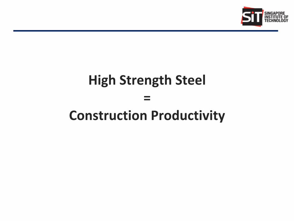
High Strength Steel =
Construction Productivity

Replacing NSS with HSS
Uncertain
performance
Construction
Total material
Strength/weight ratio
Productivity

Benefit of using HSS
Material &
Fabrication Cost
Strength
Fab
ric
ati
on
Co
st
Weig
ht
Weight of Steel
Maximization
of Benefit
Example for
built-up box section
S460 !
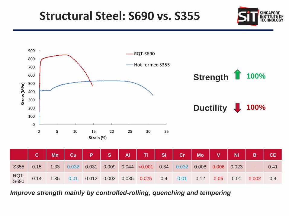
Structural Steel: S690 vs. S355
0
100
200
300
400
500
600
700
800
900
0 5 10 15 20 25 30 35
Stre
ss (M
Pa)
Strain (%)
RQT-S690
Hot-formed S355
Strength
Ductility
100%
100%
C Mn Cu P S Al Ti Si Cr Mo V Ni B CE
S355 0.15 1.33 0.032 0.031 0.009 0.044 <0.001 0.34 0.032 0.008 0.006 0.023 - 0.41
RQT-
S690 0.14 1.35 0.01 0.012 0.003 0.035 0.025 0.4 0.01 0.12 0.05 0.01 0.002 0.4
Improve strength mainly by controlled-rolling, quenching and tempering
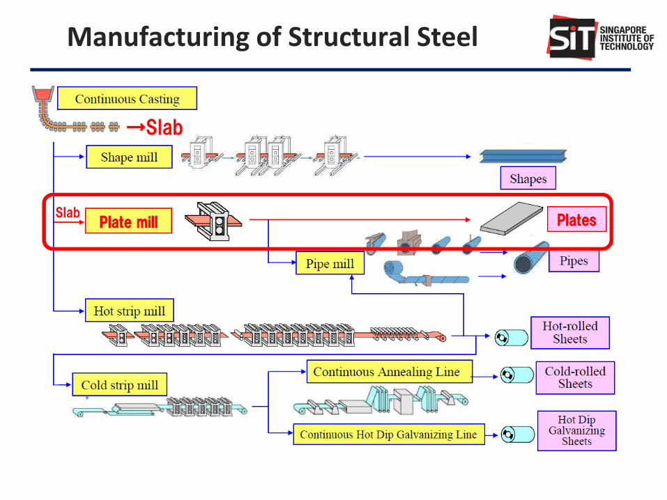
Manufacturing of Structural Steel
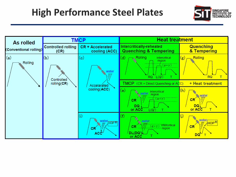
High Performance Steel Plates

Reinforcing Steel Structural Steel
A B C Normal strength High strength
Yield strength (MPa)
400 to 600 ≤ 460 ≥ 460 ≤ 690
Modulus of elasticity (GPa)
200 210
ft/fy or fu/fy ≥ 1.05 ≥ 1.08 ≥ 1.15 < 1.35
≥ 1.10 ≥ 1.05
≥ 1.10 (NA)
Elongation (%) ≥ 2.5 ≥ 5.0 ≥ 7.5 ≥ 15 ≥ 10
Ultimate strain εu ≥ 15εy
Trend is towards use of higher grade but more stringent ductility requirements in terms of tensile/yield strength ratio and elongation.
Structural Steel vs. Reinforcing Steel

EC2 EC3 EC4
Concrete
Normal C12/15- C90/105
_
C20/25 - C60/75
Light weight
LC12/13 – LC80/88 LC20/22 - LC60/66
Reinforcing steel 400 - 600 N/mm2 _ 400 - 600 N/mm2
Structural steel _ ≤ 690 N/mm2 ≤ 460 N/mm2
Material Comparison in Eurocodes
Same trend towards use of higher grade concrete, leads to greater construction productivity. However, the ranges in EC4 are more restricted than those in EC2 and EC3, WHY?

Current Design Issues in using High Strength Steel Reinforcing Bars in EC2

Steel Rebars (from SS2 to SS560)
Standard Grade Yield strength
Re (MPa)
Tensile/yield strength ratio, Rm/Re
Elongation at fracture A5 %
Elongation at maximum force, Agt %
SS2: 1987 460 460 1.15 12 - SS2: 1999 500 500 1.05 14 -
SS560: 2016
B500A 500 1.05 - 2.5 B500B 500 1.08 - 5.0 B500C 500 ≥ 1.15, < 1.35 - 7.5 B600A 600 1.05 - 2.5 B600B 600 1.08 - 5.0 B600C 600 ≥ 1.15, < 1.35 - 7.5
Mechanical Properties
13

Benefits of Grade 600 Rebar
Item Description
Steel Saving Potential to reduce steel reinforcement – up to 20% compared to current Grade 500 rebar
Steel Fabrication Up to 20% less workers are needed
Logistics Less trucks carrying steel reinforcement on the roads – up to 20% less
Site Crane Handles up to 20% less steel and frees up crane time for other construction activities thereby speeding up construction
Concrete Saving Reduction in structural element size is possible when used together with appropriate higher grades of concrete which will result in further overall dead weight reduction
Storage Space Space required for site storage of steel reinforcement can be reduced by about 20%
Time Reduction Overall time savings can be accomplished by factoring in the above items
Cost Reduction Overall cost reduction can be achieved from reduced usage of material, manpower, construction time, etc
14
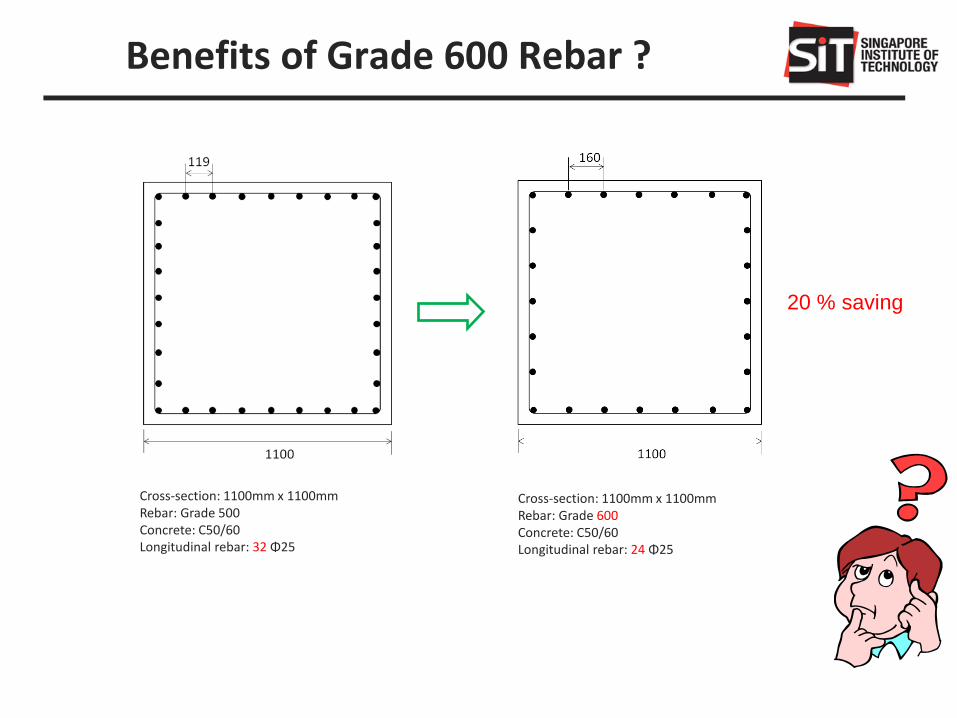
Benefits of Grade 600 Rebar ?
Cross-section: 1100mm x 1100mm Rebar: Grade 500 Concrete: C50/60 Longitudinal rebar: 32 Φ25
Cross-section: 1100mm x 1100mm Rebar: Grade 600 Concrete: C50/60 Longitudinal rebar: 24 Φ25
20 % saving
15

Cross-section: 1100mm x 1100mm Rebar: Grade 500 Concrete: C50/60 Longitudinal rebar: 32 Φ25
Cross-section: 900mm x 900mm Rebar: Grade 600 Concrete: C90/105 Longitudinal rebar: 24 Φ25
Rebar: 20 % saving Concrete: 33% saving
16
Benefits of Grade 600 Rebar ?
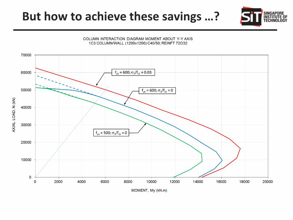
But how to achieve these savings …?

Design Provisions in EC2
Stress-strain relationships
Three types are allowed in SS EN1992-1-1, i.e. • Parabolic-rectangular diagram
• Bi-linear stress-strain diagram
• Rectangular diagram
18

Design Provisions in EC2
Concrete compression strain In design, failure of concrete in compression is defined by means
of limiting compressive strains. EN1992-1-1 adopts a limit of εcu2 (or εcu3 if bi-linear diagram is
used) for flexural, a limit of εc2 or εc3 for pure axial compression, and a interpolation between the value of εcu2 for flexure and εc2 for axial load for combined bending and compression.
Grade εcu εc2 εc3
≤ C50/60 0.0035 0.0020 0.00175
C55/67 0.0031 0.0022 0.00180
C60/75 0.0029 0.0023 0.00190
C70/85 0.0027 0.0024 0.00200
C80/95 0.0026 0.0025 0.00220
C90/105 0.0026 0.0026 0.00230 0
10
20
30
40
50
60
70
0 0.001 0.002 0.003 0.004
C80/95
C70/85
C50/60
C90/105
C60/75
C55/67
Str
ess
Strain 19

Strain Compatibility
When high strength steel rebar is used in RC column, there is much concern about early concrete crushing; when the yield strain of the steel exceeds the crushing strain of concrete (generally, εc = 0.002 (≤C50/60) for pure compression), concrete crushing occurs before yielding of the reinforcing steel. Thus, the high strength steel rebar cannot develop its full yield strength, and there is no benefit in using it at all.
20

Axially Loaded Columns
η fcd
σsc
σsc
The maximum pure compressive strain is εc2 or εc3 when the whole section is under pure compression.
εc2
Cross-section strain stress
Grade εc2 εc3 f y,εc2 f y,εc3
≤ C50/60 0.0020 0.00175 460 403
C55/67 0.0022 0.00180 506 414
C60/75 0.0023 0.00190 529 437
C70/85 0.0024 0.00200 552 460
C80/95 0.0025 0.00220 575 506
C90/105 0.0026 0.00230 598 529
Limiting Concrete Strain & Maximum Strength of Grade 600 Rebar
,f E f cy s sc s yk
εsc
21

Columns under Compression and Bending
c2 = 0.002
(a) Pure compression (b) x > h (c) x = h (d) x < h
εsc
h
x
εc2 x/(x-3h/7) εcu = 0.0035
x
The maximum compressive strain is assumed to lie between εc2 (or εc3) and εcu when the section is in compression and bending.
N
M
A
B
C
D
E
For case (a) and (b), strain compatibility issue should be considered.
22
εcu = 0.0035

Confined Concrete Strain
2 2
2 2
2
2
1.0 5.0 0.05
1.125 2.5 0.05
0.2
ck,c ck ck ck
ck,c ck ck ck
c2,c c2 ck,c ck
cu2,c cu2 ck
for
for
f f f f
f f f f
f f
f
Confinement can be generated by adequately closed hoops or links. This results in higher strength and higher critical strain.
SS EN1992-1-1 Clause 3.1.9
23

Confined Concrete Models
1. CEB-FIP Model Code 1990
2. FIB Model Code 2010
3. JB Mander’s Confined Concrete Model
4. D Cusson’s Confined Concrete Model
5. F Legeron’s Confined Concrete Model
The confinement depends on many factors including • The diameter, layout, spacing and number of the longitudinal reinforcement bars • The diameter and spacing of the transverse reinforcement bars • Yield stresses of the reinforcement bars • Concrete strength
24
Various confinement models under study:
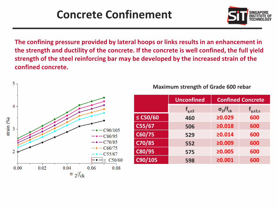
Concrete Confinement
Unconfined Confined Concrete
fy,ε2 σ2/fck fy,ε2,c
≤ C50/60 460 ≥0.029 600
C55/67 506 ≥0.018 600
C60/75 529 ≥0.014 600
C70/85 552 ≥0.009 600
C80/95 575 ≥0.005 600
C90/105 598 ≥0.001 600
Maximum strength of Grade 600 rebar
The confining pressure provided by lateral hoops or links results in an enhancement in the strength and ductility of the concrete. If the concrete is well confined, the full yield strength of the steel reinforcing bar may be developed by the increased strain of the confined concrete.
25

Concrete Confinement
0
100
200
300
400
500
0.002 0.0025 0.003 0.0035 0.00426
fyk= 600 MPa , Φ10
fyk= 500 MPa , Φ10
Lin
k S
pacin
g s
(m
m)
Strain εc2,c
500
520
540
560
580
600
620
0 200 400 600
Link Spacing s (mm)
f y,ε
c2,c (
N/m
m2)
fyk= 600 MPa , Φ10
fyk= 600 MPa , Φ12
26

Concrete Confinement
Grade 600;
σ2/fck =0.025
Grade 600;
σ2/fck =0
Grade 500;
σ2/fck =0
27
0
10000
20000
30000
40000
50000
60000
0 2000 4000 6000 8000 10000
N (kN)
M (kNm)

Current Design Issues in using High Strength Steel Reinforced Concrete (SRC) Columns in EC4

Composite Columns:
• Achieve overall enhancement in strength and stiffness
• Provide fire-protection and buckling resistance for steel section
Steel:
High Strength High Ductility
Concrete:
Lower Cost Good Fire Resistance
Composite Columns in EC4
SRC CFT

Limitation of Design Codes
The ranges in EC4 are more restricted than EC2 and EC3, the question is WHY?
• Lack of test data and experience in designing composite members with high strength materials
• Strain compatibility problem
Codes Steel yield strength (N/mm2)
Concrete cylinder strength (N/mm2)
EC4 235 ~ 460 20 ~ 60
EC2 - 12 ~ 90
EC3 235 ~ 690 -

Concrete Filled Tubular (CFT) Columns
Concrete Filled Tubular Columns with High Strength Materials - An Extension of Eurocode 4 Method to C90/105 Concrete and S550 Steel
Took advantage of concrete confinement provided by the outer steel tube and validated against test database !
Question: what about SRC Columns?
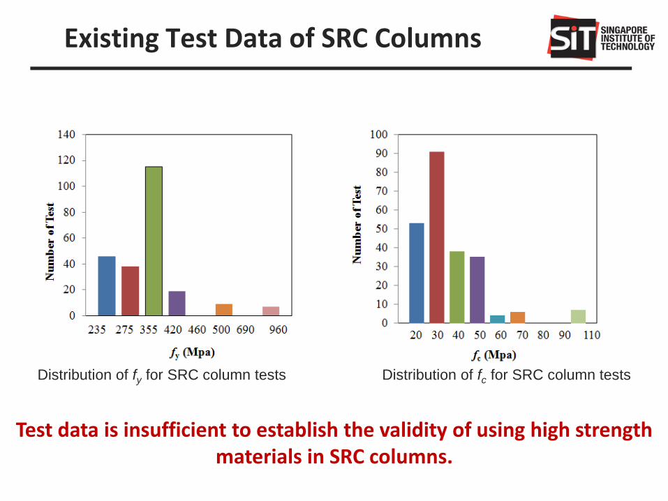
Existing Test Data of SRC Columns
Distribution of fy for SRC column tests Distribution of fc for SRC column tests
Test data is insufficient to establish the validity of using high strength materials in SRC columns.

Comparison Study
SRC columns with normal strength materials (≤ S460)
(fc ≤ 50 MPa and fy ≤ 460 MPa)
Test/EC4
Mean Value 1.21
SRC columns with high strength materials (≥ S460)
(fc > 50 MPa and fy > 460 MPa)
Code Conservative
Safe !
Test/EC4
Mean Value 0.87
Code Overestimates
Test Results
Not Safe !

• Much concern about early concrete crushing in SRC columns with high strength steel.
• If the yield strain of the steel exceeds the crushing strain of concrete, concrete crushing occurs before yielding of the steel – ‘strain compatibility’.
• High strength steel cannot develop its full yield strength.
• Full Plastic Method in EC4 is not applicable for high strength steel (fy ≥ S460).
Why Not Safe?

Strain Compatibility Method
, max af E f y c y
y c
y af E y
Grade S235 S275 S355 S420 S460 S500 S550 S620 S690
≤ C50/60 235 275 355 420 420 420 420 420 420
C55/67 235 275 355 420 460 464 464 464 464
C60/75 235 275 355 420 460 483 483 483 483
C70/85 235 275 355 420 460 500 504 504 504
C80/95 235 275 355 420 460 500 525 525 525
C90/105 235 275 355 420 460 500 546 546 546
Maximum Strength of Steel before Concrete Crushes
Steel grade εy (‰)
S235 1.12
S275 1.31
S355 1.69
S420 2.00
S460 2.19
S500 2.38
S550 2.62
S620 2.95
S690 3.29
Yield Strain of Steel
Grade εc2 (‰)
≤ C50/60 2.0
C55/67 2.2
C60/75 2.3
C70/85 2.4
C80/95 2.5
C90/105 2.6
Strain of Concrete at Peak Strength

Confined Concrete Method
Confinement can be provided by closed hoops or lateral links. The confining pressure results in higher strength and higher strain of the concrete.
1. CEB-FIP Model Code 1990
2. FIB Model Code 2010
3. JB Mander’s Confined Concrete Model
4. D Cusson’s Confined Concrete Model
5. F Legeron’s Confined Concrete Model
The confinement depends on many factors
• The diameter, layout, spacing and number of the longitudinal reinforcement bars
• The diameter and spacing of the transverse reinforcement bars • Yield stresses of the reinforcement bars • Concrete strength
Various possible confinement models:

Confined Concrete Method
• For SRC columns, confinement can be provided by the lateral links and steel section.
• Eurocodes only provides the stress-strain relationship of confined concrete in RC columns.
• How to predict the stress-strain behaviour of confined concrete in SRC columns?
Confinement zones in SRC columns Confined concrete Model for RC Members (EC2)

Confined Concrete Method
2 2
2 2
2
2
1.0 5.0 0.05
1.125 2.5 0.05
0.2
ck,c ck ck ck
ck,c ck ck ck
c2,c c2 ck,c ck
cu2,c cu2 ck
for
for
f f f f
f f f f
f f
f
EN1992-1-1 Clause 3.1.9
2 0.5ck wdf
The effective lateral compressive strength due to confinement σ2:
EN 1998-1
2
0 0 0 0
61 1 1
2 2= - =
i
n s
b s s
b h b h
yd
wd
cd
n
Volume of hoops=
Volume of confined concrete
= s
f
f

Test/EC4 Test/EC4,u Test/EC4,c
Mean 0.87 1.11 0.94
Comparison Study
Comparison of test data and codes on SRC columns with high strength materials
EC4 is the resistance by EC4 plastic method;
EC4,u is the resistance by EC4 considering strain-compatibility;
EC4,c is the resistance by EC4 considering strain-compatibility & confinement effect
according to EC2;
Conclusions:
• Full Plastic Method in EC4 is unsafe and cannot be used. • Strain Compatibility Method is too conservative, uneconomical. • Confinement model in EC2 cannot be directly applied to SRC columns
with high strength materials, unsafe to use. • Requires some modifications for SRC columns.

Current Restrictions in Extension of Existing Design Rules up to Grade S690 in EC3-1-12

Intensification of Low-Density Developments: Functional Bridging Buildings
MNDRF SUL2013-4
Weight/m2= 311 kg/m2 (Grade S690) + 150 kg/m2 (Grade S355) + 22 kg/m2 (Y1860S7 15mm)
Combined S690 + S355
Weight/m2= - + 896 kg/m2 (Grade S355) + 22 kg/m2 (Y1860S7 15mm)
Only S355

Submerged Arc Welding (SAW)

Electro-Slag Welding (ESW)

Heat Input & Size of HAZ – Productivity

Heat Input for Various Welding Process

Possible Effects of Welding
1. HAZ: Mechanical property alteration
including strength, toughness and ductility
2. High residual stress caused by thermal
expansion & contraction and phase
transformation
3. Distortion
Influences of residual stress
Compression: Failures due to instability
or buckling
Tension: Premature failures and fatigue
“The effect on the performance of welded
structure is significant only on phenomena
that occur under low applied stress. The
phenomena include Brittle fracture,
fatigue and stress corrosion cracking.”
– AWS Welding Handbook
HAZ by high heat input SAW
Residual stress distribution in butt welding

ADDITIONAL RULES TO EN 1993-1-8
Angles connected by one leg and other unsymmetrically connected members in tension: Eccentricity must be considered
Rules for Lug angles are not applicable
Rules for Resistance of welded connections for under matched welding electrodes
Rigid-plastic and elastic-plastic global analyses are not applicable
Rules for semi-rigid joints are not applicable
Rules for design resistance of basic components – valid only for bolt failure mode: concrete in
compression, base plate in bending under compression and tension, anchor bolt in tension
Rules for hollow section: static resistance should be reduced by a factor of 0.8 (0.9 for S355-S460)
ADDITIONAL RULES TO EN 1993-1-10: Rules for maximum permissible element thickness
47
EN1993-1-12: Extension to S690
Reduction Factor of 0.8 for S690
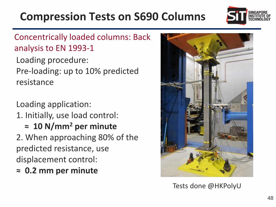
Compression Tests on S690 Columns
Loading procedure: Pre-loading: up to 10% predicted resistance Loading application: 1. Initially, use load control: ≈ 10 N/mm2 per minute 2. When approaching 80% of the predicted resistance, use displacement control: ≈ 0.2 mm per minute
Tests done @HKPolyU
Concentrically loaded columns: Back analysis to EN 1993-1
48

Column Test Results
0.0
0.1
0.2
0.3
0.4
0.5
0.6
0.7
0.8
0.9
1.0
1.1
0.0 0.2 0.4 0.6 0.8 1.0 1.2 1.4 1.6 1.8 2.0
Re
du
ctio
n fa
cto
r χ
Non-dimensional slenderness, λ
Test C1PA
Test C3QA
Test C2QA
Test C2PATest C3PA
Test C2S series
Test C3S series
Test C1S seriesTest C4QA
Curve a0
Curve c
Test C4PA
Current design rules for cross-section resistances are considered to be applicable to S690 steel columns.
Section classification for determination of cross-section resistances may be enhanced.

Equivalent T-Stub Joint
Why model and test simple T-Stub Joint?
HAZ at Weld Toe
Plastification failure – Formation of Plastic Hinge at Weld Toe
tfmm
δ
θ
θ
F
M1
M2
Deformation of the T-stub joint (Mode 1)

Effect of HAZ
Displacement load EN1993-1-8 Design plastic resistance (Component/Yield line Method)
Thickness (mm)
Test Results (kN) EC3 Eqns.
(kN) Diff 3
(%)
Diff 4
(%) Test1 Test2
Test
Average Eqn. 1 Eqn. 2
RQT-S690 16 217.8 219.5 218.7 210.3 225.6 4.0 -3.1
TMCP-S385 16 146.5 142.0 144.3 117.3 125.9 23.0 14.6
tfmm
δ
θ
θ
F
M1
M2
Deformation of the T-stub joint (Mode 1) Safe for NSS but not safe for HSS!
𝐹 =4𝑀𝑝𝑙 ,1,𝑅𝑑
𝑚 1
𝐹 =(8𝑛 − 2𝑒𝑤)𝑀𝑝𝑙 ,1,𝑅𝑑
2𝑚𝑛 − 𝑒𝑤(𝑚 + 𝑛) 1
Eqn. (1)
Eqn. (2)
Note: Eqn. (2) takes the effect of washer and bolt heat into consideration
𝑀𝑝𝑙 ,1,𝑅𝑑 = 𝑙𝑒𝑓𝑓 (𝑡
2)2𝑓𝑦 1
Design moment resistance of the section
Load carrying capacity is fully dependent on the plastic hinges!
In EC3, three failure modes, namely (1) complete yielding of the flange, (2) bolt failure with yielding of the flange and (3) bolt failure are identified. - Mode 2 and 3 depend on the strength of the bolts, while mode 1 depends on the strength of the steel.

Reduction Factor for Plastic Resistance
𝐹 =2𝑀𝑝𝑙 ,1,𝑅𝑑
𝑤𝑡 + 2𝑀𝑝𝑙 ,1,𝑅𝑑𝑏ℎ
𝑚=4(
𝐻𝐴𝑍)𝑀𝑝𝑙 ,1,𝑅𝑑
𝑚 1
𝐹 =(8𝑛 − 2𝑒𝑤)(2𝑀𝑝𝑙 ,1,𝑅𝑑
𝑤𝑡 + 2𝑀𝑝𝑙 ,1,𝑅𝑑𝑏ℎ )/4
2𝑚𝑛 − 𝑒𝑤(𝑚+ 𝑛)=(8𝑛 − 2𝑒𝑤)(𝐻𝐴𝑍
)𝑀𝑝𝑙 ,1,𝑅𝑑
2𝑚𝑛 − 𝑒𝑤(𝑚 + 𝑛) 1
𝐻𝐴𝑍
=2𝑀𝑝𝑙 ,1,𝑅𝑑
𝑤𝑡 + 2𝑀𝑝𝑙 ,1,𝑅𝑑𝑏ℎ
4𝑀𝑝𝑙 ,1,𝑅𝑑=
𝑀𝑝𝑙 ,1,𝑅𝑑𝑤𝑡
2𝑀𝑝𝑙 ,1,𝑅𝑑+ 0.5 1
Simply multiply 𝐻𝐴𝑍 to the EC3 equations!
𝐻𝐴𝑍 is in fact a moment resistance ratio:
weld toe over the normal cross section
Modified first yield resistance
Eqn. (3)
Eqn. (4)
𝐹 =4𝑀𝑝𝑙 ,1,𝑅𝑑
𝑚 1
𝐹 =(8𝑛 − 2𝑒𝑤)𝑀𝑝𝑙 ,1,𝑅𝑑
2𝑚𝑛 − 𝑒𝑤(𝑚 + 𝑛) 1
Eqn. (1)
Eqn. (2) Cross-section
at the weld toe

𝜀𝐻𝐴𝑍 = 𝑓𝑦 ,𝐻𝐴𝑍/𝑓𝑦 1
𝜌𝐻𝐴𝑍 = 𝑑𝐻𝐴𝑍/𝑡 1
𝐻𝐴𝑍
=𝜀𝐻𝐴𝑍𝜌𝐻𝐴𝑍
2
2−
1− 𝜌𝐻𝐴𝑍 2
2𝜀𝐻𝐴𝑍− 𝜌𝐻𝐴𝑍 + 1.5 1
How to obtain Reduction Factor 𝐻𝐴𝑍
𝑑𝐻𝐴𝑍 + 𝑑1 + 𝑑2 = 𝑡 1
𝜎𝑑𝑦𝑡/2
−𝑡/2
= 𝑓𝑦 ,𝐻𝐴𝑍𝑑𝐻𝐴𝑍 + 𝑓𝑦𝑑1 − 𝑓𝑦𝑑2 = 0 1
𝑀𝑝𝑙 ,1,𝑅𝑑𝑤𝑡 = 𝜎𝑦𝑑𝑦
𝑡/2
−𝑡/2
= 𝑙𝑒𝑓𝑓 [𝑓𝑦 𝑑2
2 + 𝑑12
2+ 𝑓𝑦 ,𝐻𝐴𝑍𝑑𝐻𝐴𝑍(
𝑑𝐻𝐴𝑍
2+ 𝑑1)] 1
𝐻𝐴𝑍
=𝜌𝐻𝐴𝑍2
2 1− 𝜀𝐻𝐴𝑍
2 − 𝜌𝐻𝐴𝑍 1− 𝜀𝐻𝐴𝑍 + 1 1
Case 2: 𝑑𝐻𝐴𝑍 is larger than the depth of the PNA (extreme case)
Reduction factor is dependent on relative yield strength and relative depth of the assumed HAZ only!
Case 1: 𝑑𝐻𝐴𝑍 is smaller than the depth of the PNA (usual case)
𝑑𝐻𝐴𝑍 + 𝑑2 = 𝑡 1
𝜎𝑑𝑦𝑡/2
−𝑡/2
= 𝑓𝑦 ,𝐻𝐴𝑍𝑑3 − 𝑓𝑦 ,𝐻𝐴𝑍(𝑑𝐻𝐴𝑍 − 𝑑3)− 𝑓𝑦𝑑2 = 0 1
𝑀𝑝𝑙 ,1,𝑅𝑑𝑤𝑡 = 𝜎𝑦𝑑𝑦
𝑡/2
−𝑡/2
= 𝑙𝑒𝑓𝑓 [𝑓𝑦𝑑2(𝑑𝐻𝐴𝑍 − 𝑑3 +𝑑22) + 𝑓𝑦 ,𝐻𝐴𝑍
(𝑑𝐻𝐴𝑍 − 𝑑3)2
2+ 𝑓𝑦
𝑑32
2] 1
In particular, if 𝜌𝐻𝐴𝑍 = 1, that is the whole weld toe thickness is fully affected by welding,
𝐻𝐴𝑍
=(𝜀𝐻𝐴𝑍 + 1)
2 1
Eqn. (5)
Eqn. (6)

Results and Parametric Study
Test average (kN) HAZ Eqn. 3 (kN) Eqn. 4 (kN) Diff 3 (%) Diff 4 (%)
218.7 0.957 201.3 215.9 8.6 1.3
0.842 177.2 190.0 23.4 15.1
LWHI, 𝑑𝐻𝐴𝑍=6, 𝜀𝐻𝐴𝑍=0.85 LWHI, 𝑑𝐻𝐴𝑍=6, 𝜀𝐻𝐴𝑍=0.75 LWHI, 𝑑𝐻𝐴𝑍=6, 𝜀𝐻𝐴𝑍=0.65
HWHI,𝜌𝐻𝐴𝑍=0.5, 𝜀𝐻𝐴𝑍=0.6 HWHI,𝜌𝐻𝐴𝑍=0.5, 𝜀𝐻𝐴𝑍=0.5
(low heat input welding)
(High heat input welding)
Note: Better results can be obtained if the evaluation of the mechanical properties of HAZ is more precise
LOW HEAT INPUT WELDING (e.g. SMAW, FCAW)
• 𝑑𝐻𝐴𝑍 will almost be constant and independent of
the thickness
• strength ratio 𝜀𝐻𝐴𝑍 will be relatively large (e.g. 0.65
to 0.85 for RQT-S690)
HIGH HEAT INPUT WELDING (e.g. ESW, SAW)
• 𝜌𝐻𝐴𝑍 will be a constant with respect to the
thickness
• 𝜀𝐻𝐴𝑍 will be relatively low (e.g. 0.5 to 0.6 for RQT-
S690)
To be precise, eqns. 5 and 6 should be used to calculate 𝑯𝑨𝒁. For design simplicity, reduction factor 𝑯𝑨𝒁 = 0.85 is recommended.
Parametric Study
Reference: M.S. Zhao, C.K. Lee, T.C Fung and S.P. Chiew, Impact of welding on the strength of high performance steel T-stub joints, to be published.

Conclusions
EC2 EC3 EC4
Concrete
Normal C12/15- C90/105
_
C20/25 - C60/75
Light weight
LC12/13 – LC80/88 LC20/22 - LC60/66
Reinforcing steel 400 - 600 N/mm2 _ 400 - 600 N/mm2
Structural steel _ ≤ 690 N/mm2 ≤ 460 N/mm2
1. Work is in progress to extend the current limitation of high strength GR600 steel rebars in RC columns in EC2.
2. Work is in progress to extend the current limitation of high strength steel of S460 in SRC columns in EC4.
3. Finally, we should use more GR600 and S460 steel to improve productivity.