SOME CONSIDERATION ON DOUBLE LAYER STRUCTURE IN...
9
IUST International Journal of Engineering Science, Vol. 19, No.5-1, 2008, Page 51-59 SOME CONSIDERATION ON DOUBLE LAYER STRUCTURE IN PLASMA ASSISTED NITRIDING OF AUSTENITIC STAINLESS STEEL N. Parvini Ahmadi & T. Czerwiec Abstract: Low temperature plasma assisted nit riding treatments of 316 stainless steel produce a complex layer constituted by tow different metastable f.c.c. solid solution denoted (ª N1 and ª N2 ). About the formation of these double layers, different hypothesis was proposed in the literature. For verifying these hypotheses, the effects of differentes conditions such as nit riding temperature, cleaning and nit riding duration and cooling state have been studied. The results show that ª N2 sub layer produce during the ion bombardment cleaning procedure, before the nit riding treatment. Also the formation of the ª N2 layer is not connected to the cooling state of the sample after nit riding treatment. Keywords: Plasma Assisted, Nit riding, Stainless Steel, Double Layer 1. Introduction 1 Stainless steel plays an important role in various sectors of industry owing to their excellent corrosion resistance. But their application is limited by their relative low hardness. During the pass two decades, much work has been carried out on the nitriding of stainless steel, so as to improve their hardness and wear resistance [1-10]. Low temperature plasma based nitriding has been proved to be an efficient way to formed a very hard and corrosion-resistant layer on the surface of austenitic steels with relative high chromium content [2, 6, 8]. Such a layer is called expanded austenite [11], ª N phase [12, 13], s phase [14] or m phase [15]. In this paper, it is called ª N phase. The possible occurrence of double layer constituted by two different metastable f.c.c. solid solutions denoted (ª N1 and ª N2 ) was reported for AISI 316 austenitic stainless steel [10, 16]. Williamson et al. [10] observed a double layer structure corresponding to two well-defined N contents: 20-26 at% in the ª N1 surface layer and 4-10 at% in the ª N2 subsurface layer when nitriding Fe-rich f.c.c. alloys. They have suggested that ª N2 formation is caused by stress-assisted diffusion. The other searchers speculated that this double layer structure is formed during the slow cooling of the substrate after nitriding. The aim of this paper is to study this double layer structure in order to verify the different hypothesis proposed in the literature. Paper first received Feb. 10 ,2003 and in revised form April, 05. 2005. N N . . P P a a r r v v i i n n i i A A h h m m a a d d i i , , Department of Materials Engineering, Sahand University of Technology, Tabriz, Iran, [email protected] T T . . C C z z e e r r w w i i e e c c, Laboratoir de Science et Genie de Surfaces (UMR CNRS 7570), Ecole des Mines , Parc de Saurupt, 54042 Nancy Cedex, France,: [email protected] 2. Experimental Details 2-1. Sample Preparation Two types of AISI 316L (13%Ni, 17%Cr, 67%Fe, 2%Mo, 0.5%Si, 0.2%Mn, 0.02%C, other balance) and AISI304 (9.5%Ni, 18%Cr, 69.43%Fe, 1%Si, 2%Mn, 0.07%C, other balance) stainless steel samples were used in this study. The samples were cut from a cylindrical bar which has been annealed at 900˚C for 24 hours, subsequently machined to a 20 mm in diameter, 4mm in thickness disk, then grounded and mechanically polished to a mirror-like finish. The samples were always polished by 1 m diamond paste and then cleaned in methanol for 15 minutes by using ultrasonic just before being places into the reactor chamber 2-2. Nitriding Process Plasma nitriding is realized using an 800 Hz pulsed Dc discharge, with a 0.8 duty cycle ratio (ratio of the pulse duration to the pulse period) in a DC pulse plasma reactor. Normally, the sample is screwed into the substrate holder so that they form a continuous surface in order to avoid edge effects. However, the substrates are placed on a flat substrate holder in some experiments in order to allow oil quenching at the end of the treatment by simply pushing the sample in a oil container. An in situ cleaning procedure, intended to remove the native oxide layer and to simultaneously heat the sample to the working temperature, is performed before the nitriding treatment in an 50%Ar- 50%H 2 plasma under a 200 Pa pressure. The nitriding treatment is then performed in a 90%N 2 - 10%H 2 gas mixture. The temperature is measured by a thermocouple embedded into the substrate holder. At the end of a normal treatment, the samples are allowed
Transcript of SOME CONSIDERATION ON DOUBLE LAYER STRUCTURE IN...
IIUUSSTT IInntteerrnnaattiioonnaall JJoouurrnnaall ooff EEnnggiinneeeerriinngg SScciieennccee,, VVooll.. 1199,, NNoo..55--11,, 22000088,, PPaaggee 5511--5599
SSOOMMEE CCOONNSSIIDDEERRAATTIIOONN OONN DDOOUUBBLLEE LLAAYYEERR
SSTTRRUUCCTTUURREE IINN PPLLAASSMMAA AASSSSIISSTTEEDD NNIITTRRIIDDIINNGG OOFF AAUUSSTTEENNIITTIICC SSTTAAIINNLLEESSSS SSTTEEEELL
NN.. PPaarrvviinnii AAhhmmaaddii && TT.. CCzzeerrwwiieecc
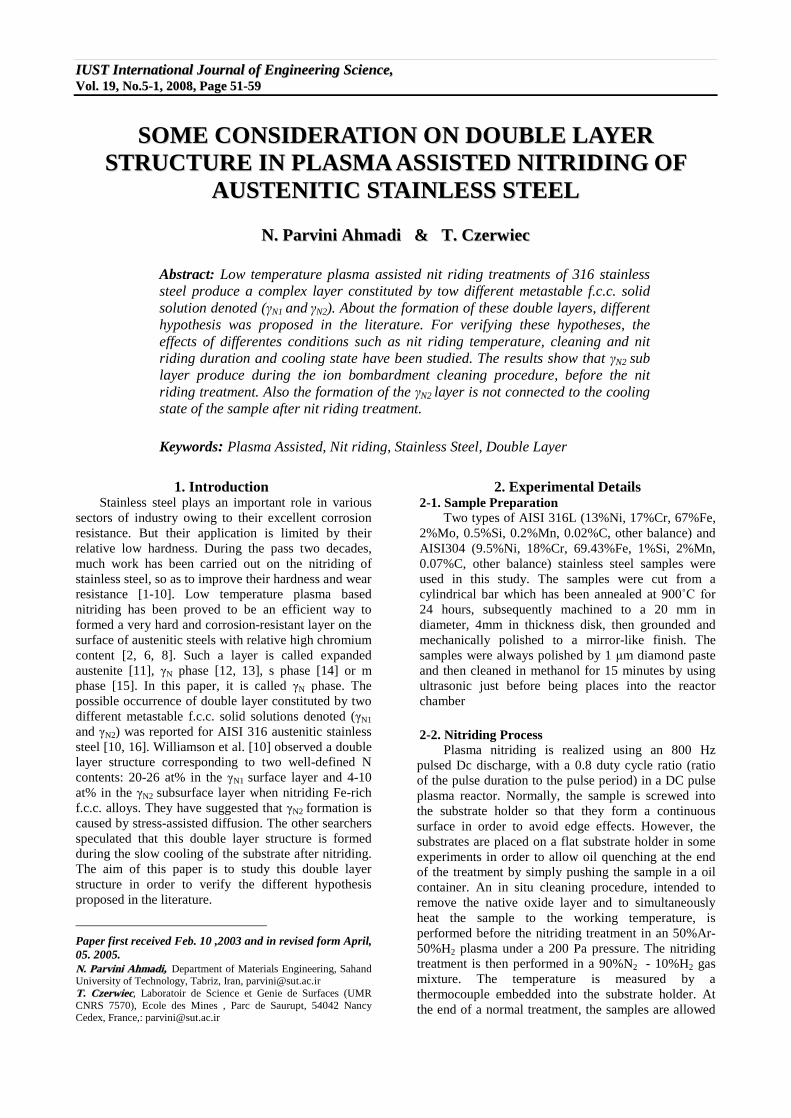
Abstract: Low temperature plasma assisted nit riding treatments of 316 stainless steel produce a complex layer constituted by tow different metastable f.c.c. solid solution denoted (ãN1 and ãN2). About the formation of these double layers, different hypothesis was proposed in the literature. For verifying these hypotheses, the effects of differentes conditions such as nit riding temperature, cleaning and nit riding duration and cooling state have been studied. The results show that ãN2 sub layer produce during the ion bombardment cleaning procedure, before the nit riding treatment. Also the formation of the ãN2 layer is not connected to the cooling state of the sample after nit riding treatment.
Keywords: Plasma Assisted, Nit riding, Stainless Steel, Double Layer
1. Introduction1
Stainless steel plays an important role in various sectors of industry owing to their excellent corrosion resistance. But their application is limited by their relative low hardness. During the pass two decades, much work has been carried out on the nitriding of stainless steel, so as to improve their hardness and wear resistance [1-10]. Low temperature plasma based nitriding has been proved to be an efficient way to formed a very hard and corrosion-resistant layer on the surface of austenitic steels with relative high chromium content [2, 6, 8]. Such a layer is called expanded austenite [11], ãN phase [12, 13], s phase [14] or m phase [15]. In this paper, it is called ãN phase. The possible occurrence of double layer constituted by two different metastable f.c.c. solid solutions denoted (ãN1
and ãN2) was reported for AISI 316 austenitic stainless steel [10, 16]. Williamson et al. [10] observed a double layer structure corresponding to two well-defined N contents: 20-26 at% in the ãN1 surface layer and 4-10 at% in the ãN2 subsurface layer when nitriding Fe-rich f.c.c. alloys. They have suggested that ãN2 formation is caused by stress-assisted diffusion. The other searchers speculated that this double layer structure is formed during the slow cooling of the substrate after nitriding. The aim of this paper is to study this double layer structure in order to verify the different hypothesis proposed in the literature.
Paper first received Feb. 10 ,2003 and in revised form April, 05. 2005. NN.. PPaarrvviinnii AAhhmmaaddii,, Department of Materials Engineering, Sahand University of Technology, Tabriz, Iran, [email protected]
TT.. CCzzeerrwwiieecc, Laboratoir de Science et Genie de Surfaces (UMR CNRS 7570), Ecole des Mines , Parc de Saurupt, 54042 Nancy Cedex, France,: [email protected]
2. Experimental Details 2-1. Sample Preparation
Two types of AISI 316L (13%Ni, 17%Cr, 67%Fe, 2%Mo, 0.5%Si, 0.2%Mn, 0.02%C, other balance) and AISI304 (9.5%Ni, 18%Cr, 69.43%Fe, 1%Si, 2%Mn, 0.07%C, other balance) stainless steel samples were used in this study. The samples were cut from a cylindrical bar which has been annealed at 900˚C for
24 hours, subsequently machined to a 20 mm in diameter, 4mm in thickness disk, then grounded and mechanically polished to a mirror-like finish. The samples were always polished by 1 ìm diamond paste and then cleaned in methanol for 15 minutes by using ultrasonic just before being places into the reactor chamber 2-2. Nitriding Process
Plasma nitriding is realized using an 800 Hz pulsed Dc discharge, with a 0.8 duty cycle ratio (ratio of the pulse duration to the pulse period) in a DC pulse plasma reactor. Normally, the sample is screwed into the substrate holder so that they form a continuous surface in order to avoid edge effects. However, the substrates are placed on a flat substrate holder in some experiments in order to allow oil quenching at the end of the treatment by simply pushing the sample in a oil container. An in situ cleaning procedure, intended to remove the native oxide layer and to simultaneously heat the sample to the working temperature, is performed before the nitriding treatment in an 50%Ar-50%H2 plasma under a 200 Pa pressure. The nitriding treatment is then performed in a 90%N2 - 10%H2 gas mixture. The temperature is measured by a thermocouple embedded into the substrate holder. At the end of a normal treatment, the samples are allowed
id6992562 pdfMachine by Broadgun Software - a great PDF writer! - a great PDF creator! - http://www.pdfmachine.com http://www.broadgun.com

52 SSoommee CCoonnssiiddeerraattiioonn oonn DDoouubbllee LLaayyeerr SSttrruuccttuurree iinn PPllaassmmaa ��
to cool in vacuum. Several samples are nitrided skipping the ion bombardment cleaning procedure, or merely ion bombarded in Ar-H2 plasma, in order to reveal the effect of the in-situ cleaning treatment on the structure of the nitrided layer. The effect of carbon contamination is investigated by introducing 0.25% CH4 into the Ar-H2 gas mixture during the ion bombardment cleaning procedure. Table 1 lists the processing conditions for various nitriding treatments.
3. Results and Discussion
3-1. Structure of the Nit Rided Layer In many published papers, a layer of metastable f.c.c. solid solution supersaturated in nitrogen, also known as
expanded austenite, ãN phase, s phase or m phase, has been reported in austenitic stainless steels which are nitrided at temperatures between 310°C and 420°C [6, 8, 11]. Fig.1shows the SEM morphology of the layer nitrided at 420°C in a 90%N2- 10%H2 gas mixture, (sample no. 1 in table 1). It is evident that nitrided layer is composed of dual layers with well-defined interface. Fig. 2(b) is the correspondent XRD pattern of this sample. A characteristic set of broad diffraction lines corresponding to the ãN phase (denoted by ãN1) can be seen in the figure. At low angles, between the diffraction lines of the ãN phase and the matrix, another peak (denoted by ãN2) can be observed on the diffraction pattern.
Tab. 1. Description of the processing conditions for plasma assisted nit riding of stainless steel samples Duration (Min) Sample�s ID Substrate
diameter(mm) Nitriding
temperature (˚C) In-situ cleaning Nitriding
Cooling state
No 1 (AISI316L) 20 420 60 60 Normal No 2 (AISI316L) 20 440 60 60 Normal No 3 (AISI304) Normal No 4 (AISI304)
20 420 60 60 Quenched in oil
No 5(a) (AISI316L) 20 420 60 60 Normal No 6 (AISI316L) Normal No 7 (AISI316L)
20 420 - 120 Quenched in oil
No 8 (AISI316L) 20 300-440 240 - Normal ( a) The gas mixture for ion-cleaning is different in this experiment: 50%Ar + 49.75%H2 + 0.25%CH4
Fig. 1. SEM micrographs of the nit rided layers for sample no.1
Fig. 2. XRD diffraction patterns for nit rided samples no. 1(b), no. 2(c) described in table 1, and for the AISI
316L substrate (a), with Co Ká radiation at the incident angle of 10º (a, b) and 4º (c).

NN.. PPaarrvviinnii AAhhmmaaddii && TT.. CCzzeerrwwiieecc 53
Fig. 3. SNMS concentration depth profiles of sample no.1 in table 1
Fig. 4. SEM micrographs of the nitrided layers for sample no.2
Fig. 3 shows the concentration depth profiles obtained by SNMS (sputtered neutral mass spectrometry) of this sample. The profile of Fe element was eliminated for the sake of convenience. It can be seen that the nitrogen content in the nitrided layer abruptly decreases at a depth of 2.5 ìm, which is approximately the thickness of the top layer. And accumulation of carbon element was observed between the depth of 2.5 ìm and 4.5 ìm, where exists the second layer. Thus, the top layer is associated to ãN1 phase which has a solid solution nitrogen contend of 10-28 at%. And the sublayer is connected to ãN2 phase, which has a relatively lower nitrogen content (≤10 at%), and a small quantity of carbon. Table 2 lists the lattice parameters of the ãN1 phase, ãN2 phase, and total layer thickness obtained under various processing parameters. As shown in fig.4, the dual layer structure can be also observed in the nitrided layer of an AISI 316L sample which was nitrided at 440ºC in the same gas mixture
(corresponding to sample no.2 in table 1). But a weak peak of CrN appears on the corresponding XRD
Pattern, fig. 2(c). This is basically in accordance with other reports that 450ºC is the upper limit temperature
for stainless steels to be nitrided without forming CrN precipitates [17]. It is difficult to find diffraction lines of the matrix on the diffraction pattern because an incident angle of 4º was applied to this sample during
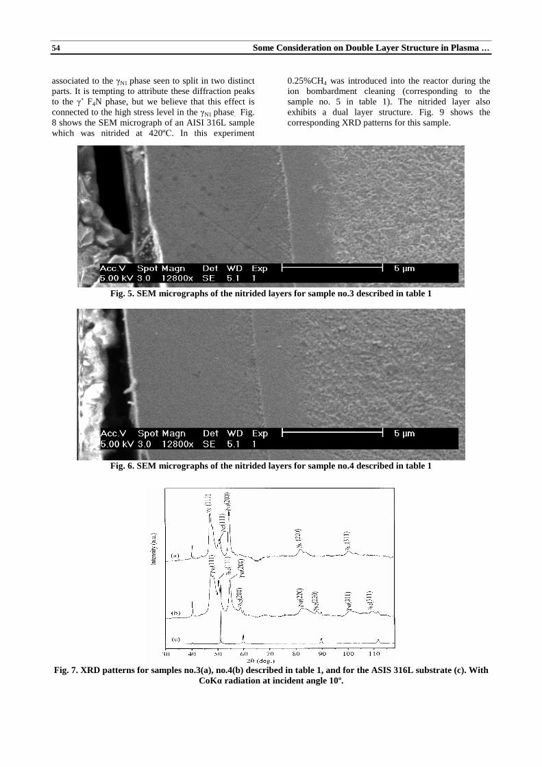
the XRD measurement. Fig. 5 and 6 are the SEM micrographs of the AISI 304 samples of the AISI 304 samples nitrided at 420ºC, which is corresponding to samples no.3 and no. 4 in table 1. The nitrided layers show a similar structure to that observed in the other type of AISI 316L, in other words, a dual layer structure can also be observed in the nitrided layer. It is noted that these two samples were nitrided at the same time under the same processing parameters, except that at the end of nitriding, sample no 3 was allowed to cool with the substrate holder, while sample no. 4 was quenched in oil. Thus this experiment indicates that formation of ãN2 layer probably is independent on the cooling state. Fig. 7 shows the corresponding XRD patterns of these two samples. In contrast to fig. 2, the diffraction lines
54 SSoommee CCoonnssiiddeerraattiioonn oonn DDoouubbllee LLaayyeerr SSttrruuccttuurree iinn PPllaassmmaa ��
associated to the ãN1 phase seen to split in two distinct parts. It is tempting to attribute these diffraction peaks to the ã� F4N phase, but we believe that this effect is connected to the high stress level in the ãN1 phase. Fig. 8 shows the SEM micrograph of an AISI 316L sample which was nitrided at 420ºC. In this experiment
0.25%CH4 was introduced into the reactor during the ion bombardment cleaning (corresponding to the sample no. 5 in table 1). The nitrided layer also exhibits a dual layer structure. Fig. 9 shows the corresponding XRD patterns for this sample.
Fig. 5. SEM micrographs of the nitrided layers for sample no.3 described in table 1
Fig. 6. SEM micrographs of the nitrided layers for sample no.4 described in table 1
Fig. 7. XRD patterns for samples no.3(a), no.4(b) described in table 1, and for the ASIS 316L substrate (c). With
CoKá radiation at incident angle 10º.

NN.. PPaarrvviinnii AAhhmmaaddii && TT.. CCzzeerrwwiieecc 55
Fig. 8. SEM micrographs of the nitrided layer for sample no.5 described in table 1.
Fig. 9. XRD patterns for sample no.5 described in table 1(a) and (b), and for the original AISI 316L substrate (c),
with CoKá radiation at incident angle 10º (a) and (c), and 25º (b)
Several explanations for the formation of the dual layer have been proposed. Williamson et al. [10] suggested that the formation of the ãN2 phase is caused by stress-assisted diffusion. Czerwiec et al. [16] proposed that ãN2 sublayer is formed during the slow cooling of the substrate after intruding. We will show a different mechanism in this paper.
4. Mechanism for the Formation of the Dual Layer Structure
Since the formation of the ãN2 layer is not necessary associated with the cooling state after a nitriding treatment, it probably occurs during the nitriding or even begins during the ion bombardment cleaning procedure. Then another two experiments were carried out, referred to as samples no. 6 and no. 7 in table 1. These two samples were nitrided at the same time under the same processing parameters, and the in-situ ion bombardment cleaning procedure just before the nitriding was skipped. After nitriding, sample no. 6 was allowed to cool with the substrate holder, while sample no.7 was quenched in oil. Fig. 10 and 11 shows the cross-sectional morphology of these two samples. No dual layer structure is observed in either of the two
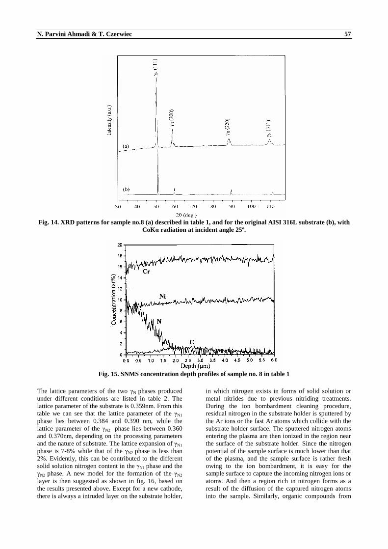
samples. This can be confirmed by the corresponding XRD patterns shown in fig. 12; no additional peaks are observed between peaks of the ãN1 phase and that of the substrate. Therefore the ion bombardment cleaning is necessary to produce the ãN2 sublayer. The primary aim of an in-situ ion bombardment cleaning just before nitriding is to remove the native oxide layer from the sample surface. But it also an important role in the formation of the ãN2 phase as being discussed above. Therefore a sample was then merely ion bombarded in a 50%Ar+50%H2 plasma without a following nitriding treatment (sample no. 8 in table1), so as to investigate the effect of this procedure on the formation of the ãN2 phase. A homogeneous layer, which is distinct from the substrate, can be observed on surface of the sample (fig. 13). The corresponding XRD pattern (fig. 14) confirms that a new phase, probably the ãN2 phase, forms owing to the ion bombardment. Fig. 15 shows the concentration depth profiles of this sample obtained by SNMS analysis. It is interesting to note that a nitrogen concentration up to near 10 at.% is found on the top surface, and the nitrogen content gradually decrease to zero at a depth of around 2.0 ìm. Since no

56 SSoommee CCoonnssiiddeerraattiioonn oonn DDoouubbllee LLaayyeerr SSttrruuccttuurree iinn PPllaassmmaa ��
nitrogen gas was introduced into the reactor during the ion bombardment, it should be the residual nitrogen in the reactor that contributes to the additional nitrogen in
the layer. A carbon rich region, also observed in sample no. 1, is observed between of 1.0 ìm and 5.5 ìm.
Fig. 10. SEM micrograph of the nitrided layer for sample no.6 in table 1
Fig. 11. SEM micrograph of the nitrided layer for sample no.7 in table 1
Fig. 12. XRD patterns for sample no.6 (a), no. 7 (b) described in table 1, and for the original AISI 316L substrate
(c), with CoKá radiation at incident angle of 10º
Fig. 13. SEM micrograph of the nitrided layer for sample no.8 described in table 1
NN.. PPaarrvviinnii AAhhmmaaddii && TT.. CCzzeerrwwiieecc 57
Fig. 14. XRD patterns for sample no.8 (a) described in table 1, and for the original AISI 316L substrate (b), with
CoKá radiation at incident angle 25º.
Fig. 15. SNMS concentration depth profiles of sample no. 8 in table 1
The lattice parameters of the two ãN phases produced under different conditions are listed in table 2. The lattice parameter of the substrate is 0.359nm. From this table we can see that the lattice parameter of the ãN1
phase lies between 0.384 and 0.390 nm, while the lattice parameter of the ãN2 phase lies between 0.360 and 0.370nm, depending on the processing parameters and the nature of substrate. The lattice expansion of ãN1
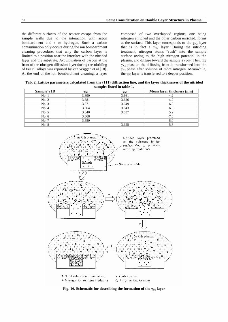
phase is 7-8% while that of the ãN2 phase is less than 2%. Evidently, this can be contributed to the different solid solution nitrogen content in the ãN1 phase and the ãN2 phase. A new model for the formation of the ãN2
layer is then suggested as shown in fig. 16, based on the results presented above. Except for a new cathode, there is always a intruded layer on the substrate holder,
in which nitrogen exists in forms of solid solution or metal nitrides due to previous nitriding treatments. During the ion bombardment cleaning procedure, residual nitrogen in the substrate holder is sputtered by the Ar ions or the fast Ar atoms which collide with the substrate holder surface. The sputtered nitrogen atoms entering the plasma are then ionized in the region near the surface of the substrate holder. Since the nitrogen potential of the sample surface is much lower than that of the plasma, and the sample surface is rather fresh owing to the ion bombardment, it is easy for the sample surface to capture the incoming nitrogen ions or atoms. And then a region rich in nitrogen forms as a result of the diffusion of the captured nitrogen atoms into the sample. Similarly, organic compounds from
58 SSoommee CCoonnssiiddeerraattiioonn oonn DDoouubbllee LLaayyeerr SSttrruuccttuurree iinn PPllaassmmaa ��
the different surfaces of the reactor escape from the sample walls due to the interaction with argon bombardment and / or hydrogen. Such a carbon contamination only occurs during the ion bombardment cleaning procedure, that why the carbon layer is limited to a position near the interface with the nitrided layer and the substrate. Accumulation of carbon at the front of the nitrogen diffusion layer during the nitriding of FeCrC alloys was reported by van Wiggen et al.[18]. At the end of the ion bombardment cleaning, a layer
composed of two overlapped regions, one being nitrogen enriched and the other carbon enriched, forms at the surface. This layer corresponds to the ãN2 layer that is in fact a ãCN layer. During the nitriding treatment, nitrogen atoms �rush� into the sample surface owing to the high nitrogen potential in the plasma, and diffuse toward the sample�s core. Then the
ãN2 phase at the diffusing front is transformed into the ãN1 phase after solution of more nitrogen. Meanwhile, the ãN2 layer is transferred to a deeper position.
Tab. 2. Lattice parameters calculated from the (111) diffraction line, and the layer thicknesses of the nitrided
samples listed in table 1. Sample�s ID ãN1 ãN2 Mean layer thickness (ìm)
No. 1 3.890 3.661 4.2 No. 2 3.881 3.626 4.7 No. 3 3.871 3.649 6.3 No. 4 3.864 3.643 6.0 No. 5 3.840 3.637 5.2 No. 6 3.868 7.0 No. 7 3.880 8.0 No. 8 3.625 5.8
Fig. 16. Schematic for describing the formation of the ãN2�layer

NN.. PPaarrvviinnii AAhhmmaaddii && TT.. CCzzeerrwwiieecc 59
5. Conclusions Plasma assisted nitriding of austenitic stainless
steel AISI 316L at 420ºC produces two distinct ãN
layers with well-defined interface: ãN1 top layer with relative high solid solution nitrogen content ranged from 10 at.% to nearly 30 at.%, and ãN2sublayer with relative low solid solution nitrogen content less than 10 at.% and a small amount of carbon. It was found that an in-situ ion bombardment cleaning in Ar+H2 plasma before the nitriding treatment is the necessary condition to produce the ãN2 layer. The formation of the ãN2 layers is not connected to the cooling state of the sample after a nitriding treatment. A model for the formation of the ãN2 sublayer is then suggested as follow: during the ion bombardment cleaning procedure, the residual nitrogen in the reactor is sputtered into the plasma owing to the bombardment of Ar species. Some of the sputtered nitrogen species are absorbed by the sample surface and then diffuses into the sample. At the same time organic compounds are also sputtered from the walls of the reactor and a redistribution of carbon and nitrogen in the sample occurs just beneath the sample surface. Thus a layer constituted by two overlapped regions with low contents of nitrogen and carbon forms during the ion bombardment cleaning, which becomes the precursor of the ãN2 sublayer during the subsequent nitriding.
References [1] Sundararaman, D., Kuppusami, P., Raghunathan, V.S.
Some Observations on the Ion Nitriding Behavior of a Type 316 Stainless Steel, Surfaces. Technology, 1983, 18(4), pp. 341-347.
[2] Zhang, Z.L,. Bell, T., Structured and corrosion resistance of plasma nitrided stainless steel, Surf. Eng. 1985, 1920, pp. 131-136.
[3] Rolinski, E., Effect of Plasma Nitriding Temperature on
Surface Properties of Austenitic Stainless Steel, Surf, Eng., 1987,3(1), pp. 35-40.
[4] Sundararaman, D., Kuppusami, P., Raghunathan, V.S., A
Study of Plasma-Nirided AISI Type 316 Stainless Steel, Surf. and Coat. Technol., 1987, 30 (4), pp. 343-354.
[5] Angelini, E., Burdese, A., de Benedetti, B., Ion-Nitriding of Austenitic Stainless Steel, Metall. Sci. Technol., 1988, 6(2), pp. 33-39.
[6] Saker, A., Leroy, C., Michel, H., Franz, H., Properties of Sputtered Stainless Steel-Nitrogen Coatings and Structural Analogy with Low Temperature plasma Nitrided Layer Austenitic Steels, Mater. Sci. Eng. A, 1991, 140 (1/2), pp. 702-708.
[7] Meletis, E.I., Yan, S., Low-Pressure ion Nitriding of AISI 304 Austenitic Stainless Steel with an Intensified Glow Discharge, J. Vac. Sci. Technol. A, 1993,11 (1), pp. 25-33.
[8] Lei, M.K., Zhang, M.K., Microstructure and Corrosion Resistance of Plasma Source ion Nitrided Austenitic Stainless Steel, J. Vac. Sci. Technol. A, 1997, 15 (2), pp. 421-427.
[9] Sun, Y., Bell, T., Sliding Wear Characteristics of Low Temperature Plasma Nitrided 316 Austenitic Stainless Steel, Wear 1998, 218 (1), pp. 34-42.
[10] Williamson, D.L., Davi, J.A., Wilbur, P.J. Effect of
austenitic stainless steel composition on low-energy, high-flux, nitrogen ion beam processing, Sur. And coat. Technol., 1998, 103/104, pp. 178-184.
[11] Blawert, C., Mordike, B.L., Jiraskova, Y., Schneeweiss,
O., Structure and Composition of Expanded Austenitic Produced by Nitrogen Plasma Immersion Ion Implantation of Stainless Steels X6CrNiTi1810 and X2CrNiMoN2253, Surf. And Coat. Technol. 1999, 116/119, pp. 189-198.
[12] Ozturk, O., Williamson, D.L., Phase and Composition
Depth Distribution Analyses of Low Energy, high flux N implant stainless steel, J. Appl. Phys., 1995, 77 (8), pp. 3839-3850.
[13] Czerwiec, T., Michel, H., Bergmann, E., Low-Pressure,
high-density plasma nitriding: mechanisms, technology and results, Surf. and Coat. Technol., 1998, 108/109, pp. 182-190.
[14] Sun, Y., Li, X.Y., Bell, T., X-ray Diffraction
Characterization of Low Temperature Plasma Modification Nitrided Austenitic Stainless Steel, J. Mater. Sci., 1999, 34 (19), pp. 4793-4802.
[15] Marchev, K., Landis, M., Vallerio, R., Cooper, C.V.,
Giessen, B.C., The m Phase Layer on ion Nitreded Austenitic Stainless Steel (III): an Epitaxial relationship Between the m Phase and the ã Parent Phase and a Review of Structural Identifications of this Phase, Surf. and Coat. Technol. 1999, 116/119, pp. 184-188.
[16] Czerwiec, T., Renevier, N., Michel, H., Low
Temperature Plasma-Assisted Nitriding, Surf. and Coat. Technol. 2000, 131, pp. 267-277.
[17] Renevie, N., Collignon, P., Michel, H., Czerwiec, T.,
Low Temperature Nitriding of AISI 316L Stainless steel and Titanium in a Low Pressure Arc Discharge, Surf. and Coat. Technol. 1999, 111, pp. 128-133.
[18] Van Wiggen, P.C., Rozendaal, H.C.F., Mitterneijer, E.J.,
The Nitriding Behaviour of Iron-Chromium-carbon Alloys, J. Matter. Sci., 1985, 20, pp. 4561-4582.