Some aspects of cold extrusion of sintered copper preforms
26
Journal of Mechanical Working Technology, 13 (1986) 339--364 339 Elsevier Science Publishers B.V., Amsterdam -- Printed in The Netherlands SOME ASPECTS OF COLD EXTRUSION OF SINTERED COPPER PREFORMS P. VENUGOPAL, S. ANNAMALAI, K.S. KANNAN and SRIRAM SRINIVASAN Department of Metallurgical Engineering, Indian Institute of Technology, Madras-600 036 (India) (Received January 24, 1985; accepted in revised form February 20, 1986) Industrial Summary In production engineering considerable attention is devoted to energy saving and to the recycling of material in the manufacture of parts. The cold processing of sintered powder-metal preforms is gaining considerable importance on these grounds, whilst the cold extrusion technique appears to be supportive, to a large extent, of this general trend. Cold extrusion is influenced by tool stresses, and the cold processing of P/M preforms by this technique accentuates the effect of tool stresses in terms of unpredictable densi- fication and internal friction. The formability is sensitive to the initial preform densities of the preforms. Cold hooker extrusion of sintered copper powder-metal preforms has been successfully carried out for varying initial preform densities of 7.64, 7.78 and 7.82 g/cc, the theore- tical (i.e. solid) density of this material being 8.95 g/cc. Experimentally observed values of maximum force have been compared with values from other sources of information concerning the estimation of forces and appropriate correction factors have been gen- erated to be used as ~ready reckoners' where P/M copper hooker extrusion is concerned. The properties -- in terms of density, hardness and toughness -- have been evaluated for these P/M extrudes and the optimal condition reported. MetaUographic examination has also been carried out for analysis of particle distribution and void closure phenomena. Fracture specimens have also been metallographed for identifying the mode of fracture. Introduction and objectives There has been a great increase in the use of powder metallurgical com- ponents due to : (i) high raw material utilisation and generation of little or no scrap; (ii) very close tolerances of the part; (iii) cost savings; (iv) possibility of densification by further mechanical working leading to properties com- parable to those of wrought parts. Many applications are listed in refs. [1--4]. Due to inherent porosity, these P/M parts suffer from low tensile strength, low ductility and poor impact and fatigue properties: these properties have been found to be density dependent. Methods such as the impregnation of a low melting point metal into the pores of the P/M part, and double pressing 0378-3804/86/$03.50 © 1986 Elsevier Science Publishers B.V.
-
Upload
p-venugopal -
Category
Documents
-
view
214 -
download
2
Transcript of Some aspects of cold extrusion of sintered copper preforms

Journal of Mechanical Working Technology, 13 (1986) 339--364 339 Elsevier Science Publishers B.V., Amsterdam -- Printed in The Netherlands
SOME ASPECTS OF COLD EXTRUSION OF SINTERED COPPER PREFORMS
P. VENUGOPAL, S. ANNAMALAI, K.S. KANNAN and SRIRAM SRINIVASAN
Department of Metallurgical Engineering, Indian Institute of Technology, Madras-600 036 (India)
(Received January 24, 1985; accepted in revised form February 20, 1986)
Industrial Summary
In production engineering considerable attention is devoted to energy saving and to the recycling of material in the manufacture of parts. The cold processing of sintered powder-metal preforms is gaining considerable importance on these grounds, whilst the cold extrusion technique appears to be supportive, to a large extent, of this general trend.
Cold extrusion is influenced by tool stresses, and the cold processing of P/M preforms by this technique accentuates the effect of tool stresses in terms of unpredictable densi- fication and internal friction. The formability is sensitive to the initial preform densities of the preforms.
Cold hooker extrusion of sintered copper powder-metal preforms has been successfully carried out for varying initial preform densities of 7.64, 7.78 and 7.82 g/cc, the theore- tical (i.e. solid) density of this material being 8.95 g/cc. Experimentally observed values of maximum force have been compared with values from other sources of information concerning the estimation of forces and appropriate correction factors have been gen- erated to be used as ~ready reckoners' where P/M copper hooker extrusion is concerned. The properties - - in terms of density, hardness and toughness -- have been evaluated for these P/M extrudes and the optimal condition reported. MetaUographic examination has also been carried out for analysis of particle distribution and void closure phenomena. Fracture specimens have also been metallographed for identifying the mode of fracture.
Introduction and objectives
There has been a great increase in the use of powder metallurgical com- ponents due to : (i) high raw material utilisation and generation of little or no scrap; (ii) very close tolerances of the part; (iii) cost savings; (iv) possibility of densification by further mechanical working leading to properties com- parable to those of wrought parts. Many applications are listed in refs. [1--4].
Due to inherent porosity, these P/M parts suffer from low tensile strength, low ductility and poor impact and fatigue properties: these properties have been found to be density dependent . Methods such as the impregnation of a low melting point metal into the pores o f the P/M part, and double pressing
0378-3804/86/$03.50 © 1986 Elsevier Science Publishers B.V.

340
and sintering, have been tried but have been found to increase the cost. The best approach would seem to be to increase the density of the part at as low a cost as possible. Metal working operations such as extrusion and hot forging are found to be costly finishing processes: higher cost is inherent with all hot-working process.
Brittle materials {i.e. those lacking in ductility) can be formed to net shape by the extrusion process, as the latter involves compressive principal stresses [5] and thus void closure and improved deformation can be anti- cipated. Cold extrusion complements the above, and affords superior mechanical properties and surface finish and minimal post-forming opera- tions.
Amongst the basic cold-extrusion processes, the viability of the cold hooker extrusion process [6] has been demonstrated for successfully ex- truding sintered-iron preforms [7]. The hooker extrusion process has been identified as a cold-extrusion technique able to produce a long tube, free from cracks and having improved properties [7]. Further, this process is also likely to afford material saving and cost reduction. A detailed product development investigation [8] into the recycling of copper powder by the hooker-extrusion technique, highlights savings of 11.65% and 16.65% in the cost of the tube and material respectively, compared to the wrought-forming route. Thus the economics of the cold-forming route for powder metal pre- forms is quite promising.
It is known that whilst deformation is assured in the cold-extrusion pro- cess, the latter is handicapped by the large tool stresses developed [5]. The forces encountered in the cold working of P/M preforms are complex due to densification, unpredictable internal friction and matrix hardening. Preforms of different initial preform densities will require different forces for the afore-mentioned reasons. Attempts are being made to study the influence of lower-level initial preform densities coupled with extrusion forming variables {deformation ratio e, strain rate $, tool angles) with a view to securing a pro- duct with a final density approaching the theoretical density. Care is also be- ing taken to ensure relatively low friction, to allow simple tooling to be used and so that less energy is expended in the processing of the preforms.
The influence of preform history. (density) and its consequent effect on tool forces forms the major consideration in the present programme of expe- rimental work.
Equations for the estimation of the maximum tool forces for the wrought equivalent of the present powder material are readily available in the litera- ture [7, 9, 10]. Experimentally observed values of maximum forces in the present work are thus~compared with those for their wrought equivalent and presented in the form of "correction factors". The basic flow-properties of the preforms are characterised by the apparent strength-coefficient K a and apparent strain-hardening exponent n a [7, 11]. Calculated values of forces for these flow properties are compared with experimentlly observed maxi- mum forces and, based on this comparison, another correction factor is

341
evolved. These correction factors can then form 'ready reckoners' capable of pre-determining the maximum forces that would be required to process the P/M part by the cold hooker-extrusion technique.
In extrusion, it is to be expected that densification is accentuated due to the constrained nature of the deformation. The influence of extrusion reduc- t ion on various preforms of different densities also forms a major part of the present investigation.
Supporting data in terms of hardness, toughness and metaUography are also furnished, from examination of the properties of the preforms and the extrudes.
Experimental plan and details
Compaction Electrolytic copper powder was chosen as the work material in the present
investigation. The chemical and sieve analysis are indicated in Table 1. Sam- ples were mixed in a d o u b l e , o n e mixer with 1% zinc stearate lubricant added as a binder for the compaction. The weighing of the requisite powder, lubricants and compacts were undertaken on an electrical balance, the weight of the powder used ranging from 180 to 190 g.
TABLE 1
Analysis report on copper powder
1 Type: Electrolytic Copper Powder 2 Chemical Analysis: Copper content 99.0% min; Oxygen content 0.5% max; Acid
insoluble 0.03% max. 3 Apparent Density a: 2.59 g/cc 4 Flow b: 43.5 s/50 g 5 Sieve Analysis c:
Size (~m) (Weight %) 200 + 160 + 0.65 125 + 11.20
90 + 27.24 63 + 27.17 50 + 4.89 50 - 28.84
aFor Method of Testing, refer to Standard B 212 - 76, ASTM Standards, Part 9, 1980. bB213 - 77, ASTM Standards, Part 9, 1980. CB214 - 76, ASTM Standards, Part 9, 1980.
The compaction tool consists of a hollow cylindrical container (OD : ID : Length = 50 : 30 : 165 mm), the inner surface of which is ground and lapped. The top punch (OD : ID : L e n g t h = 30 : 14.5 : 160 mm) and the bot tom counter-punch (OD : ID : Length = 30 : 14.5 : 130 mm) slide inside

342
the container. A core rod (14.5 mm dia and 300 mm length) is concen- trically located and guides the top and bot tom punches. The container rests on a spring, the compression of the spring during compaction providing rela- tive movement of the container, necessary to reduce the density-gradient effect on the compact. This tool set was assembled in a 1000 kN double-ac- tion deep-drawing hydraulic press, a laboratory-fabricated load cell being used to measure the compacting force.
Compaction loads of 170, 210 and 250 kN were used to provide green billets of varying preform density: these particular loads were employed so that the billets as prepared would be identical to those used in the work of ref. [11] ; their similarity then allowing the f low properties determined in ref. [11] to be extended to the present work. These f low properties were consulted for theoretical estimation of forces. Compaction conditions in terms of pressing time (5 s) were also established so as to be similar to the conditions prevailing in the work of ref. [11] .
Copper powder m i x e d with
I°1o lubr icant ]
I Compacted at 170, 210, 250 kN
I Sintered in cracked ammonia
(L) 500°C - 1 h ( tubl-icant expuEsion) (~i) 900°C- I h (Sinter ing)
~TLThh n n ~ n g [ Bi l le t 1 preparation ]
[ I Boring of preform--q
to ID 17.2 mrn to | suit hooker mandrelJ
I Nosing of one end | to ~ 22.3mm and5 J turn length with 4 5 ° t a p e r
S i n t e r e d c o m p a c t
?.-_ ¢ 3O --~
Machined bi l le t
Fig. 1. Sintering and billet-preparation schedule.
343
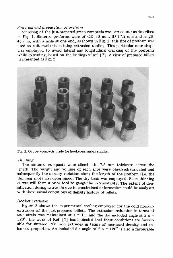
Sin tering and p reparation o f preform Sintering of the just-prepared green compacts was carried out as described
in Fig. 1. Sintered preforms were of OD 30 mm, ID 17.2 mm and length 45 mm, with a nose at one end, as shown in Fig. 1: this size of preform was used to suit available existing extrusion tooling. This particular nose shape was employed to avoid lateral and longitudinal cracking of the preforms while extruding, based on the findings of ref. [7] . A view of prepared billets is presented as Fig. 2.
Fig. 2. Copper compacts made for hooker-extrusion studies.
Thinning The sintered compacts were sliced into 7.5 mm thickness across the
length. The weight and volume of each slice were observed/evaluated and subsequently the density variation along the length of the preform (i.e. the thinning plot) was determined. The dry basis was employed. Such thinning curves will form a prior tool to gauge the extrudability. The extent of den- sification during extrusion due to constrained deformat ion could be analysed with these initial conditions of density history of billets.
Hooker extrusion Figure 3 shows the experimental tooling employed for the cold hooker-
extrusion of the just-prepared billets. The extrusion reduct ion in terms of true strain was maintained at e = 1.1 and the die included angle at 2 a = 120°: the work of Ref. [7] has indicated that these conditions are favour- able for sintered P/M iron extrudes in terms of increased density and en- hanced properties. An included die angle of 2 a = 120 ° is also a favourable

3 4 4
F ig . 3. D e t a i l s o f the extrusion t o o l i n g a n d t h e h y d r a u l i c p r e s s : a - - p r e s s r a m ; b - - l o a d
ce l l ; c - - e x t r u s i o n - p u n c h s h o e ; d - - p u n c h b o d y ; e - - d ie c l a m p - r i n g ; f - - s t r o k e a r r e s t e r ; g - - c o n t a i n e r s h r i n k - r i n g ; h - - d i e sh r ink - r ing ' , i - - d ie b o l s t e r .
condition for extruding P/M nosed preforms free from lateral cracks. This angle is also the optimal included angle from the point of view of low force requirement (based on the differentiation of force equations for the wrought equivalent, Ref. [5] ).
To register the punch force and stroke, transducers available in the labora- tory were employed, namely: a load cell of sensitivity 600 kN per 100 microstrain; a Hottinger--Baldwin Messtechnik LVDT; a HBM amplifier; and a Hewlett--Packard x--y recorder.
Successful extrudes of various preform densities can be seen in Fig. 4.
Force Punch force--stroke plots were recorded during extrusion, from which the
necessary experimental force particulars were evaluated.
Maximum force Frnax From the punch force--stroke plots maximum extrusion force Fma x was
determined. This peak through force is essential for: (i) Designing the tool members; (ii) Selection of a suitable press; (iii) Forming a basis for esti- mating the magnitude of the frictional force encountered during extrusion.

345
Fig. 4. Successful cold extrudes of sintered copper preforms.
Mean Force Fmean The mean force was evaluated over a stroke length of 30 mm in the pre-
sent investigation: this force is useful for estimating the work done in the process. A comparison of mean force with respect to maximum force affords an assessment of the frictional forces encountered in the extrusion process, Ref. [5].
Correction factor ¢1 The flow properties of the wrought equivalent (electrolytic copper) such
as the strength coefficient K and the strain-hardening exponent n are avail- able based on the work of Ref. [12]. These flow properties were consulted and the equation postulated in Ref. [5] for estimating the hooker-extrusion force was used to calculate the theoretical force for the hooker extrusion of the wrought equivalent. Experimentally observed values of maximum force (based on the present work) were compared with those calculated, to provide correction factor ¢ ~.
Correction factor ¢ Values of maximum force for P/M preforms were calculated, consulting
the flow properties of Ref. [11] and using the equation of Ref. [5]. Com- parisons were made with reference to the present experimentally observed values, to provide correction factor ¢ 2.
Correction factor ¢3 Experimental values of maximum forces were available based on the work
of Ref. [13] for the hooker extrusion of electrolytic wrought copper at a strain of e = 1.1 and for a die included angle of 2 a = 120 °. These values were

346
compared with the presently observed experimental values to provide correc- tion factor ¢3.
If, therefore, any of the publications referred to earlier is available as a source, then the force required for P/M copper hooker extrusion can be pre- determined by applying the appropriate correction factor.
Energy Using Fmeaa and the appropriate standard stroke length (the stroke length
used in the evaluation of Fmean) the energy was calculated, to afford a basis for comparison. The cost of the product is directly affected by the energy consumed by the process, and this latter quantity also enables the forming efficiency and the system efficiency to be evaluated. Energies calculated in this manner should also complement the information given by the variation of mean forces, for varying preform densities.
Mechanical properties Hooker extrudes of varying preform densities were cut into slices and each
slice was then weighed for use in producing the thinning plot, referred to earlier. The sliced specimens of both preforms and extrudes were tested to determine their Vickers hardness. Special notched tubes were also prepared of P/M extrudes to determine their toughness. To compare toughness, iden- tical wrought extrudes already available in the laboratory were subjected to impact testing. From density evaluation, it should be possible to examine the correct combination of preform density coupled with extrusion to ensure near theoretical density with least gradient of densification across the length of the extrude. The hardness and toughness properties should be capable of providing information concerning the optimal combination of varying pre- form density and extrusion.
MetaUographic examination A scanning electron microscope was employed to obtain metallographs of:
Copper powder; green compacts; sintered compacts; extruded P/M tube; and fractured P/M tube, to provide useful information concerning the particle distribution and size, void closure and the nature of fracture.
Results and discussions
Sintered powder-metal copper preforms Figure 5 shows the mean initial preform densities of compacts made under
compaction loads of 170, 210 and 250 kN. The numerical values and per- centage thinning of these compacts are given in Table 2.
Whilst the absolute mean densities increase with increase in compacting loads, the thinning~ffect increases with increase in compacting loads (+_ 0.615, +- 1.2565 and +- 2.07% for mean densities of 7.64, 7.78 and782 g/cc respectively). This trend is unexpected, because with increase in compacting

347
rz 7.~,
>,
o
Curve a - Compacted at a load of 175 KN Curve b - Compacted at a load of 210 KN Curve c - Compacted at a load of 250 KN
8.0 ^ ?
. . . . _ ~ . . . . . M~A_. ~ : _
• MEAN P1 =.7.64 g/cc J (1
7.6 •
7.4
0 5 10 15 20 25 30 35 40 {~5
Distance f rom punch face, mm
Fig. 5. Dens i ty va r ia t ion along the length o f the p r e f o r m ( ' t h inn ing ' curves).
T A B L E 2
T h i n n i n g and m e a n densi t ies of p r e fo rms (se.e also Fig. 5)
M e a n p r e f o r m dens i ty p (g /cc)
% Density gradient (thinning)
(+) (-) Mean
7.64 0 .78 0 .45 + 0 .615 7 .78 1.31 1 .22 +- 1 .265 7 .82 1.91 2.23 + 2.07
pressure, frictional constraints along the compact length will be of minor magnitude. This controversial trend (of greater thinning effect with increase in compacting pressure) appears to be peculiar to the copper P/M preforms. I t has been observed [14], that the optimal compacting pressure with refer- ence to wall thickness should be employed to secure minimal thinning-effect when processing copper P/M preforms: Higher pressure could lead to the entrapment of gases or moisture, leading to the formation of pockets or voids.
Neglecting the marginal thinning (maximum + 2.07% only), it would al- ways be desirable to have a preform with higher initial starting preform den-
348
sity for further mechanical working. It is to be expected that mechanical working such as extrusion will always complement densification due to the constrained deformation. Thus, such preforms, which have a greater thinning- effect, could be monitored (in respect of the thinning effect) after extrusion.
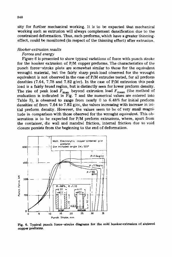
Hooker-extrusion results Forces and energy Figure 6 is presented to show typical variations of force with punch stroke
for the hooker extrusion of P/M copper preforms. The characteristics of the punch force--stroke plots are somewhat similar to those for the equivalent wrought material, but the fairly sharp peak-load observed for the wrought equivalent is not observed in the case of P/M extrudes tested, for all preform densities (7.64, 7.78 and 7.82 g/cc). In the case of P/M extrusion this peak load is a fairly broad region, but is distinctly seen for lower preform density. The rise of peak load Fma x beyond extrusion load Fmean (the method of evaluation is indicated in Fig. 7 and the numerical values are entered into Table 3), is observed to range from nearly 0 to 6.48% for initial preform densities of from 7.64 to 7.82 g/cc, the values increasing with increase in ini- tial preform density. However, the values seem to be of very small magni- tude in comparison with those observed for the wrought equivalent. This ob- servation is to be expected for P/M preform extrusions, where, apart from the container, die wall and mandrel friction, internal friction due to void closure persists from the beginning to the end of deformation.
i Matt: E lect ro ly t ic copper sintered p/m J : ] preform
6 0 0 ~ - - - - - ~ J Die included Qngle 2~,: 120 °
=
/ / / i ~--~I p=7.B2 ] - ......... 4 . . . . . . .
...< o, r . . . . tt- 0 i billet e~trude ! I I I
0 5 10 15 20 25 30 35
Punch Stroke. mm
Fig. 6. Typical punch force--stroke diagrams for the cold hooker-extrusion of sintered copper preforms.

349
450
300
150
F'mo X
Frneon F30 -
o
f
0 10 20 ~ .~ 30ram
t : Copper Material sintered preform Die included angle
2~C :120 '
,~ p2 = 7."/8g
i 3O
-I Stroke~ mm
Fig. 7. Method adopted for the estimation of Fmean from the punch force--stroke plot.
TABLE 3
Experimental values from punch force -- stroke plot
Preform Fma x (kN) Fmean (kN) Energy (kJ) density p (g/cc) (Fmean × 30 ram)
7.64 495 495 14.85 7.78 475.66 446.0 13.38 7.82 465.16 435.0 13.05
The Fmean values calculated for an arbitrary stroke length o f 30 mm were used to estimate the energy required for the hooker extrusion of all pre- forms. As can be seen from Fig. 8, the Fma x and Fmean decrease with in- crease in initial preform densities, the difference between the two quantities increasing considerably with increase in preform density. This illustrates the strong influence o f preform density on the energy consumed in densifica- tion, matrix hardening and associated internal friction. This energy can as- sume a specific minimum fixed value for near theoretical density, when the extrusion will then be analogous to extruding the wrought equivalent mate- rial. It is reasonable to conclude here that a greater initial preform density will require a lower maximum tool force, thus minimising the internal fric- tion of the work material.
Figure 9 presents the energy required for extruding copper preforms o f different initial preform density. The trend of reducing energy with in- creasing initial preform density is consistent with the above-mentioned reasoning. It is to be concluded here that to produce a P/M preform in an

350
510
490 m m
c~ 470 LL
x 1,50
b.
430
!
i'
!
• i "$7! 7.5
i
iMoterial :Copper lelntered preform
L ~ /Fmax
\ / Fmean
7.6 7.7 7.8
Sintered density ~ ~ g/cc
7.9
Fig. 8. Variation of Fma x and Fmean with density of the sintered preform.
IS0
w
x ¢ g
14.0
?' 13.s
13.0 I
$7.4 75 7.6 7.17 7.8 7.9
5intsred density ~ ~ g/cc
Fig. 9. Variation of extrusion energy with density of the sintered preform.
economical way, the initial preform density should be restricted to a higher value: lower values of initial density will lead to the persistance of internal friction to the end of the deformation. Thus, initial preform densities of less than 7.78 g/cc (87% of theoritical density) are not preferable, even though associated favourable conditions of least thinning could be anticipated.
Correction factors ¢1, ~2, ~3 The need for evolution of certain correction factors has been outlined
earlier. Established analytical equations in respect o f the estimation of maxi- mum punch forces for cold extrusion and cold hooker~extrusion, in partic- ular o f wrought materials, are available in the work of Lange [5] . Experi- mental values can also form a source of knowledge of the maximum forces concerning wrought,equivalent materials. The third source of information concerning the evaluation of maximum forces can be in terms of consulting the flow properties of sintered P/M preforms, such as Ka and na.

351
1.4
q~.1,3
o1.1 LJ
1.0
o
\_
\ I ~ for caLcuiotedi
wrought equWoient
\ ~1 = -0.25,o + 3-24
I , i 7.2 7.6 8.0 8.4 8.88.92 9.2
Preform density ~ ~glcc Fig. 10. Correction factor for calculated values o f max imum force for the wrought equivalent.
2.2
c~ ¢), 1.9
~ 1 . 6 o =
1.3
for calculated P/M equivalent
",\ $ = -0.77J'+ 7-93 "~ 2
t.o . 1 i 7.2 7.6 8.0 8.4 8.8 8.92 9.2
Preform density ~ ~ g[cc
Fig. 13.. Correction factor for maximum force values calculated for P/M preforms using flow-curve data.
1./*
1 . 3
1"2
2 1"1
~.0 o ~
0
\
~3 = - 0'24P~.13
7.2 7-6
(~ for expfl wrought equivalent
\ 10
8"0 8"4 8"8 $92 9'2 Preform Density ~o, g /cc
Fig. 12. Correction factor for experimentally-observed values of maximum force for the wrought equivalent.

352
The present experimental observations concerning the evaluation of maximum forces are compared with all possible sources of information and projected in the form of correction factors ¢1, ~2 and ¢3 in Figs. 10--12, the method o f evaluation of the correction factors being indicated in Table 4, with the latter expressed as simple equations therein. These equations can thus form basic tools for pre-determining the maximum forces required to hooker-extrude a sintered P/M copper preform. It is also interesting to note that the correction factors associated with the calculated wrought-equivalent and the experimental wrought-equivalent ¢1 and ~3 (Figs. 10 and 12) assume a value of uni ty at the full theoretical density when the equation postulated by Lange [5] (see Table 4) for wrought-equivalent copper is applied directly to the P/M component . The equations for ~, and ¢ 3,
1 = -0 .25p + 3.24
¢3 = -0 .24p + 3.13
are nearly identical, which also substantiates the validity of Lange's equa- tion. To sum up, the following correction factors in the form of equations, viz.,
¢, =-0.25p + 3.24 (1)
¢2 =-0.77p + 7.93 {2)
¢3 = -0.24p + 3.13 (3)
T A B L E 4
Calculat ion o f cor rec t ion factors Basis reference [ 5 ] I
Fret Ftdeal + Fshear Fk~ion I Y =Ken (for wrought )
= + K a ena (for P/M)
F ' e a l - " tel e, • 1 /2"
Ff~iction = , T D 0 - 1 . Y0"P + 2 - Y m e a n - e l " ~ ' A 1 + A I " Y m e a n ' P "e , sin 2a Tan
1 e ~ ei YMean = - j K - e n . d el 0
Preform 1 2 3 4 Correct ion Densi ty Fac t Fcalcu~ted Fe~ptl Fmletth~e d Fac to r ~ p(g/cc) (kN) Wrought Wrought P/M = l a /2 a
expt l Based on Based on Based on [12] [13] [11]
Correc t ion Correc t ion Fac to r ~ ~ Fac to r ~ 3 = l a / 4 a = l a / 3 a
7.64 495 366.83 370 240.19 1.349 2.06 1.33 7.78 475.66 366.83 370 235.72 1.296 2.01 1.28 7.82 465.15 366.83 370 265.16 1.268 1.75 1.25
a re fe r to co lumn no.

353
have been evolved, where p is the initial mean preform-density of the copper compact.
By consulting any o f the three sources of information cited above, the hooker-extrusion punch forces can be evaluated using Lange's equation. The force so evaluated will have to be multiplied by the appropriate correction factor to provide an estimate of the maximum tool forces for P/M extrusion.
These correction factors are valid for the present experimental conditions.
Density of the hooker extrudes Following the. procedure outlined earlier, sliced specimens of hooker ex-
trudes for the determination o f the variation o f the density over the length of the extrude were prepared, for mean preform-densities o f 7.82, 7.78 and
9.4
9 2 P/M Extrude
9 ' 0
88
86
,/i f
I I
8-/,
~8.2 . . . .
Q
7 .8
7"6
%
1 I" 45 ~i
//'/.//////A i
+ IIIIIIII~G + 1 Preform
= . / P 3 =7.~2!
7"&
7-2
0 10 20 30 40 50 60 70 Distance from punch face, mm
Fig. 13. Dens i ty variation o f a cold P/M coppe~ extrude for a billet o f dens i ty p = 7 .82 g/cc.

354
7.64 g / c c , results being presented as Figs. 13--15 respectively. For com- parison purposes, the densifications plots corresponding to the preforms are also entered at the lower half of these figures. As anticipated, due to con- strained deformation with the three principal stresses being compressive, the densities o f the extruded tubes are always greater than those o f the pre- forms. It is also interesting to observe that the severe thinning of the pre- forms is reduced to a negligible minimum value in the extrudes. It can be ob- served that preform mean densities o f 7.82 and 7.78 g/cc when cold hooker- extruded at a reduction of e = 1.1 with a die included angle 2~ = 120 ° yield almost identical densities o f the extrudes, ranging in value from 8.864 g/cc to 8.876 g/cc which latter are in excess o f 99% of the theoretical density.
9 4
9.2
9.0
8"8
8 .6
8 .4
u "~8'2
. s.o a
7-8
t
f ," ( ¢" ( l l ( l I~
P/M E x t r u d e i
7 ' 6 - -
7 ' 2 ~ -
0 10
. . . . . i . . . . .
i
- 1 .... i .......... !- -
i r , . ~ 4 5 ""1
P r e f o r m
L
I
l - !
" - .... 4 i i
l i i 1 i
1 20 30 40 50 60 70
Ois lonce froffl p u n c h ~ace , m m
Fig. 14. As for Fig. 13 for p = 7 .78 g/cc.

355
9 4
9.2
9 ' 0
8"8
8'6
o . .
PIN Extrude
r l i
i I '
6-4 } ~. 45 "l
! " / / / / / / / / . 4 8.2. ~
~. ~" J i l l ¢ - 1 P r e f o r m
~a0 r a
7.8
_ ~ ,~.,,p.~_ . ~ _ ~ 6L ?.6
I" J
7.t.
7.2
0 10 20 30 40 50 Distance from punch face. mm
Fig. 15. As for Fig. 13 for p = 7.64 g/cc.
60 70
Hardness, Toughness and Metallographic Properties Since hardness is invariably of higher magnitude in P/M components (a
unique property achieved in P/M processing), cold extruded P/M compo- nents can give an abnormally enhanced hardness -- as much as 225% increase in hardness relative to that of the sintered P/M preforms of the present inves- tigation, see Figs. 16--18. However, with increase in hardness the ductil i ty or toughness shows a negative trend and it becomes necessary to ascertain the correct combination of these two mechanical properties from the service point of view. Reference to Fig. 19 shows that preforms made below 7.78 g/cc (87% of theoretical density) will have a poor toughness. A suitable tran- sition in terms of good toughness appears to be at this preform density (87%

356
I 1 F r ~ - - l;7,> V 7 0 ~ I
p ~ b':./ ........... -~i --:~ t 1 S 0 ~ - - [ - - " P / M Cold e x t r u d e - - . . . . . . . i
,3o! i ] i ~ T [ m-----~ C -
11o . . . . . 2 L 2 i i 21 • !
g Ioo ~ - - - - ~ F V//////?//I , . . . . .
= 9 o ~ - . - - - " t F~/./////i -! - : i / S i n t e r e d P r e f o r m
I t ~ l • . . . . T - I . . . . .
I i I I i '
l i i I I i ;
6 o - - - - p f i i I , i ,
~o,- ~ 1 - 1 7 ! ........ ' - 7 ~ 4
0 10 20 30 40 50 60 70 D i s t Q n c e f r o m p u n c h f a c e , m m
Fig. 16. Hardness variation of a cold P/M copper extrude for a billet of density p = 7.82 g/cc.
of theoretical density). For comparison purposes, wrought-equivalent hooker extrudes were also tested for impact strength under identical conditions and gave a value of 29 kgf m(284J ) as against the maximum of 3.6 kgf m(35J) encountered in the present investigations. This low toughness results froii, the pockets and voids that are present in the as-hooker-extruded specimen, see Fig. 24. Perhaps a post-sintering operation done on these extrudes could lead to pore closure and consequently improve toughness. The decision ob- viously rests with the user.
The train of metallographic prints presented as Figs. 20--24 shows inter- esting features of particle size, shape, orientation, bonding and void closure due to the appropriate sequential operations. It is also noted from the frac- tograph of the extruded sample, as in Fig. 25, that fracture occurs by a mixed ductile and brittle mode, lessening the concern regarding the possible catastrophic failure of these P/M parts in service.

357
16(3 •
150
140
130
120
110
9O
80
I 7o ~I
- - - - PIM Cold extrude --
L \ x \ \ \ . ~ "
T 45 ", r / / / / / / / / / 1
e, t I / / / / / / / /
Sintered Preform
7 0
6 0
0 10 20 30 40 50 Distance / ram punch face, mm
Fig. 17. As for Fig. 16 for p = 7.78 g/cc.
60 70
Conclusions
Successful cold hooker~xtrusions have been carried out on sintered P/M copper preforms of initial preform densities of 7.64, 7.78 and 7.82 g/cc. Based on the experimental results on the preparation of preforms and extru- sion studies the following conclusions are drawn.
On the preforms The absolute mean densities show an increase with increase in compaction
loads, but least thinning effect is found in compacts compacted at the lowest load of 175 kN and the effect increases with increasing compacting load (-+ 0.615, _+ 1.265 and + 2.07% for mean densities of 7.64, 7.78 and 7.82 g/cc respectively). This trend appears to be peculiar and unique to copper P/M preforms. Mechanical working such as extrusion will always comple- ment densification by constrained deformation and this could be used to

358
J¢
§ o
140
130
120
110 - -
, o . . . . . . .
" ~ l~ . , . . . . . . . . . . 1=-3 q' 150 ~ " - - P I M Cold e x t r u d e - - /
I I
I i
J i
f
9 o - - ~
J
70 !
6o i L
i" 4! "1 / / / / / / / / / j
/ / / / / , / / / ]
Sintered Preform
i
1 ! I _
4O
0 10 20 30 40 50 60 Dis tonce f r o m p u n c h foce , mm
70
Fig. 18. As for Fig. 16 for p = 7 .64 g/cc.
4 0
"G
E - 3 . 0 c_.
Jo
e~
; 2-o
0 7-4
[. 60ram -, I / / / / / / l f / / / / / 11
Impoct Sl~cimen
O,D 2 2 3 m m t .D 17 m m _
k ~ J
7.5 7"6 7"7 7.8
P r e t o r m D e n s i t y p g l c c
79
Fig. 19. Impact-test data for PfM extrudes.

359
Fig. 20. S.E.M. of t he coppe r p o w d e r used.
Fig. 21. S.E.M. o f t h e green c o m p a c t for a c o m p a c t i o n load o f 250 kN (equ iva len t to a pressure o f 461.5 N/ram2).

3 6 0
Fig. 22. S .E .M. o f a s i n t e r e d c o m p a c t w h e r e p = 7 . 8 2 g / cc .
Fig. 23 . A s fo r Fig . 22 w h e r e p = 7 . 7 8 g /cc .

361
Fig. 24. S.E.M. of a P/M ex t rude for a p r e fo rm of dens i ty p = 7.78 g/cc.
Fig. 25. S.E.M. of a f rac tured P/M co ld-ex t ruded copper tube for a p r e f o r m of dens i ty p = 7.82 g/cc.

362
monitor compacts having a greater thinning effect, simultaneously gaming the advantages o f a greater initial preform density for further mechanical working.
Forces and energy for the extrudes Peak through load and extrusion load The typical punch force--stroke plot of a P/M preform extrusion, even
though similar to that o f a wrought material, shows a broad peak-region. This effect is found to be distinct for lower preform densities with the value of Fma x showing an increase of from 0 to 6.48% for an increase in preform density of from 7.64 to 7.82 g/cc: however this value is of minor magnitude in comparison with values for wrought material. I t can thus be concluded that in addition to the friction due to the container and to the die wall, the internal friction due to void closure persists from the beginning to the end of deformation in the extrusion of preforms.
Fma x and Fmeaa show a decreasing trend with increasing preform density and the gap between Fma x and Fmean also widens with increasing densities. It can thus be seen that tool forces can be minimised by starting with a higher preform density. It is also noted that the energy for extrusion shows a down- ward trend with increase in preform density. Thus, in conclusion, it can be stated that to produce a P/M component in an economical way, the initial preform density should be restricted to a higher value.
Optimal conditions of preform density for minimum force and energy It is also to be noted that preform densities lower than 7.78 g/cc afford
little or no difference in the values of Fma x and Fmean. This shows that the non-steady state of extrusion persists to the end of the deformation, due to the high internal friction resulting from void closure in preforms with low preform densities. Its effect on the process of extrusion is to increase the ex- trusion force and energy, thus making the process expensive and defeating a major main objective of the production engineer. It is to be concluded that preforms of densities lower than 7.78 g/cc (87% theoretical density) are not viable from the point of view of force- and energy-minimisation and hence are to be avoided, even though the associated favourable condit ions of least thinning could be anticipated.
Correction factors Correction factors have been evaluated using various sources of reforma-
tion to provide the maximum extrusion force values, and subsequent com- parison has been made with experimentally obtained values for the extrusion of P/M preforms. It is interesting to note that correction factors calculated for the wrought equivalent using the equation postulated by Lange and the present experimental wrought-equivalent correction factors @ 1 and @ 3 assume a value of unity at theoretical density. Correction factors in the form of equations have been envolved in the present work:

363
¢ 1 = -0.25p + 3.24 (1)
¢2 =-0 .77p + 7.93 (2)
¢3 = -0.24p + 3.13 (3)
where p is the mean preform-density. By consulting any of the three sources of information cited, hooker-ex-
trusion punch forces can be evolved using Lange's equation. This force has to be multiplied by the corresponding correction factor to afford an estimate of the maximum force for P/M extrusion. These factors are valid for the present experimental conditions.
Densities of the Hooker extrusion The density of the extrudes show a 12--14% increase over the initial pre-
form densities, which is expected due to the constrained deformation, with the three principal stresses being compressive during extrusion. The severe thinning of the compacts is also restrained by the extrusion process to a minimum value in the extrudes. It has been observed that preforms of den- sity 7.82 and 7.78 g/cc yield almost identical densities of the extrudes of 8.864 and 8.876 g/cc, which latter represent over 99% of the theoretical density of copper.
Hardness, toughness and metallurgical properties The hardness of the extrudes shows a 225% increase over that of the pre-
forms and a value higher than that of wrought copper, which is a character- istic feature in P/M processing. However, with this increase in hardness, the toughness or ductili ty shows a negative trend due to incomplete pore closure in the extrude, as confirmed by the SEM photograph of the extrude. Condi- tions of processing for a correct combination of toughness and hardness -- which are the two main mechanical properties of any engineering material -- are found to be at a preform density greater than 7.78 g/cc (87% of the theo- retical density of copper), after which transition to higher values of tough- ness is obtained. However, it is noted from the metallographic prints of the fractured surface of the extrude, that the fracture is a mixed ductile and brittle mode, lessening the concern regarding a possible catastrophic failure of such P/M parts in service. In conclusion, it is felt that a post-sintering operation on these extrudes may lead to complete pore closure and thus im- proved toughness.
References
1 H.H. Hausner, Forging of powder metallurgy preforms. New Perspectives in Powder Metallurgy, 6 (1973) 1.
2 C.R. Weymueller, "Cold extrusion of Steels -- Its Promises and Problems. Source book on Cold Forming, ASM, Metals Park, Ohio, 1975.
3 R.J. Dower and G.H. Miles, The cold extrusion of mild steel billets produced by

364
powder metallurgical techniques. Modern Developments in Powder Metallurgy, VII (1974) 175--201.
4 K. Obara, Y. Nishino and Sa1~o, The cold forging of ferrous P/M preforms. Modern Developments hn Powder Metallurgy, VII, (1974) 423--440.
5 K. Lange, Lehrbuch fur Umform Technik, Vol. If. Springer Verlag, Berlin Heidelberg New York, 1974.
6 C.I.R.P. Production Engineering Dictionary, Vol. 5, Cold Forging and Cold Extru- sion. Verlag W. Giardet, Essen, definition number 5126, 1969.
7 S. Venkatraman, Hooker Extrusion of Sintered Iron Preforms. M.S. Thesis, I.I.T., Madras, 1983.
8 K.S. Kannan and Sreeram Srinivasan, A Feasibility Report for Setting up a Copper Tube Making Industry. Metallurgical Plant Design Report, I.I.T., Madras, 1984.
9 K. Sieber, Cold Extruding in Europe, Metal Progress, 99 (Jan 1971) 93--98. 10 V.D.I. Guidenlines 3185, Calculation of Punch Pressure, Force For Extrusion of
Steel at Room Temperature: Vol. I forward Solid Extrusion; Vol. II Can Backward Extrusion; Vol. III Hollow Forward Extrusion. Dusseldorf, VDI Verlag, (ICFG, Data Sheets 1/70, 2/70, 3/70) 1970.
11 V. Venkatramani and Vijay Jagannathan, Some Studies on Apparent Strength Co- efficient and Apparent Strain Hardening Exponent of Sintered P/M Copper Com- pacts. B. Tech Project Report, LI.T., Madras, 1984.
12 P. Venugopal, Effect of Friction and Temperature on the Combined Forward and Backward Can Extrusion. Ph.D. Thesis, I.I.T., Madras, 1982.
13 C. Chandramohan, Some Studies on Hooker Extrusion of Copper. M.Tech Thesis, I.I.T., Madras, 1983.
14 P.W. Taubenblat, Importance of copper in powder metallurgy -- a review. Int. J. Powder Metallurgy and Powder Tech., 10 (1974) 169--184.