Some Aeroelastic Aspects of Slender Wings Design · PDF fileA cantilever slender wing has been...
39
DIASP UAVNET Meeting N.5 Eilat, 30-31 October 2002 Some Aeroelastic Aspects of Slender Wings Design Giacomo FRULLA Politecnico di Torino, Dept. Of Aerospace Eng. [email protected]
Transcript of Some Aeroelastic Aspects of Slender Wings Design · PDF fileA cantilever slender wing has been...

DIASP
UAVNET Meeting N.5
Eilat, 30-31 October 2002
Some Aeroelastic Aspects of Slender Wings Design
Giacomo FRULLA
Politecnico di Torino, Dept. Of Aerospace Eng.

U.S.A. Project for High Altitude PlatformU.S.A. Project for High Altitude Platform
www.dfrc.nasa.gov/Projects/Erast (1994)
DIASP

DIASPEC-5FP (2000-2002)
HELIPLATnnhh
HELINETHELINET
A.S.I. (1995-2000)
HAVE-UAV ( High Altitude Very-long Endurance/ Unmanned Air Vehicles) capable of remaining aloft for very long period of time (9-12 months) by a solar-powered and fuel cells system.

HELIPLAT® (HELIos PLATform)
® Trademark of Dept. of Aerospace Engineering of Politecnico di Torino
WT=8000N; Wpl=1000N; Preq=6kW; Ppl=0.8kW; Vc=71 km/h (TAS); n max=3.1
Sw=176.5m2; b=73m; ARw=30.2; Croot=2.97m; taper r=0.32 S ht=28m2; b=17.5m; AR ht=11; C = 1.6m.
HALE - UAV Solar Platform Concepts
UAVNET Meeting N.5 - Eilat, 30-31 October 2002

DIASPnnhh
HELINETHELINET
CASA :1) Single CFRP elements: wing tubular spars and ribs, horizontal and vertical tail tubular spars and ribs, booms. 2) Metal fittings .
POLITO-DIASP: 1) Assembling of different parts of the aircraft (wing, horizontal and vertical tails, booms). 2) Assembling the whole aircraft. 3) Perform static tests up to the design loads 4) Find the correlation with the numerical analysis.
Scaled Prototype ManufacturingHELIPLAT

UAVNET Meeting N.5 - Eilat, 30-31 October 2002
TYPICAL AEROELASTIC PROBLEMS:
FLUTTER
LOAD DISTRIBUTION
BUFFETING
DYNAMIC LOADS
DIVERGENCE
CONTROL EFFECTIVENESS AND REVERSAL
DIASP G.Frulla – DIASP- Politecnico di Torino

LOAD DISTRIBUTION – During the flight the deflection of structure tends to redistribute the air-loads in a significantly different way. It is of course necessary a specific verification of the structural design. The case of a swept wing is presented in fig.1-5. The elastic deflection increases the lift within the fuselage, moving the center of pressure inboard rather than outboard as for straight wings .
UAVNET Meeting N.5 - Eilat, 30-31 October 2002
(figure 1.5 - after Bisplinghoff)(figure 5.17 - after Chiocchia)

UAVNET Meeting N.5 - Eilat, 30-31 October 2002
Qualitative comparison of critical speeds
(figure 1.8 - after Bisplinghoff)

UAVNET Meeting N.5 - Eilat, 30-31 October 2002
Aeroelastic behavior : General trends
(figures after Dowell)

UAVNET Meeting N.5 - Eilat, 30-31 October 2002
SLENDER WING : Structural considerations
The concept “slender” has to be defined in a coherent way avoiding not justified simplification in the model. The isotropic beam structural problem with a solid or closed form section is analyzed according to Cicala’s point of view as an example (finite modulus and maximum stress applied to the structure is reduced to the order ε). Let us introduce:
XLh ε=/ Zk ε=Yερ ≈
If a bending strain of order 1 is expected, then x+z=1 : that is X=1,Z=0 if dimensional ratio is of order EPS. This configuration is defined as ROD. It assumes a finite curvature variation and displacements of the same order as the beam length. The Euler critical stress in this case is :
222 / επσ ≈= AlEIC
G.Frulla – DIASP- Politecnico di Torino

UAVNET Meeting N.5 - Eilat, 30-31 October 2002
If again a bending strain of order 1 is expected, then x+z=1, but with X=0.5,Z=0.5 then the finite curvature variation and displacements remain of the same order as the section dimensions. The Euler critical stress in this case is :
επσ ≈= 22 / AlEIC
This configuration is defined as BEAM (classical CLT beam).
An interesting observation regards the applied loads. Considering a ROD cantilever with a transversal load F, the maximum bending moment is M=FL=2σI/h. If the maximum tension is of , M is as F. Adding a longitudinal load of the same order 4, the longitudinal traction stress is of order 2 lower than the maximum bending stress and for this reason negligible. This is a not-extensional configuration.
1ε 4ε
G.Frulla – DIASP- Politecnico di Torino
UAVNET Meeting N.5 - Eilat, 30-31 October 2002
INFLUENCE OF AEROELASTIC PHENOMENA ON DESIGNModern aircraft design and advanced aircraft design have to cope with
aeroelastic effects.
The aeroelasticity is defined (Cox and Pugsley) as: Substantial interaction among the aerodynamic, inertial, structural forces that act upon and within the flight vehicle.
(figure from Kolonay 2001)
DIASP

UAVNET Meeting N.5 - Eilat, 30-31 October 2002
2,222110022
1,122110011
12210,0022110000
2])[1/(2])[1/(
)(2])[1/(
GuGu
ueG
=+++−=+++−
∆−∆++=+++−
σσσννσσσσννσ
ξωξωσσσννσ
)()()(
1,22,112
100,22,002
200,11,001
uuGuuGuuG
+=∆++=∆−+=
σξωσξωσ
)2)(*(*20,0221122,11,12,1211,2222,11
Gu+++=−+ σσνσσσ
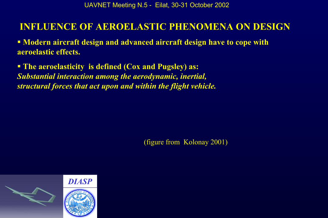
02,221,120,022,121,110,012,021,010,00=++=++=++ σσσσσσσσσ
G.Frulla – DIASP- Politecnico di Torino
UAVNET Meeting N.5 - Eilat, 30-31 October 2002
(after Cicala 1985, Frulla 1999, Frulla 2001)
G.Frulla – DIASP- Politecnico di Torino

UAVNET Meeting N.5 - Eilat, 30-31 October 2002
Simple model:
(figure from Isaaks)
G.Frulla – DIASP- Politecnico di Torino

UAVNET Meeting N.5 - Eilat, 30-31 October 2002
G.Frulla – DIASP- Politecnico di Torino
Table TA1 (P is the ratio of the initial pitch freq. with flap freq. , Q the ratio of the lag freq. with flapfreq., alfa is the flap freq. assumed unitary)
Static position(rad) P Q Alfa0 6.007 0.5 0.998
0.05 6.005 0.497 1.00230.1 5.99 0.489 1.009
0.15 5.98 0.475 1.0220.2 5.97 0.455 1.04
0.25 5.95 0.43 1.060.3 5.93 0.399 1.09
Table TA2 (P is the ratio of the initial pitch freq. with flap freq. , Q the ratio of the lag freq. with flapfreq., alfa is the flap freq. assumed unitary)
Static position(rad) P Q Alfa0 2.004 1.98 0.999
0.05 2.202 1.821 1.00150.1 2.453 1.681 1.009
0.15 2.756 1.563 1.020.2 3.114 1.462 1.04
0.25 3.531 1.37 1.060.3 4.005 1.285 1.09

UAVNET Meeting N.5 - Eilat, 30-31 October 2002
DYNAMIC BEHAVIOR OF A CANTILEVER BEAM : TIP MASS EFFECT (by Da Silva and Hodges). A comparison between different approximation was done in order to verify if the usual procedure is correct.
(figure 1 from Da Silva – Hodges)
The effect of tip displacement in function of non-dimensional tip mass is reported in table for zeropitch (see specific paper for other beam data):
v/l Freq.a Freq.b P0.011 2.36 0.607 0.473
0.0218 1.69 0.428 0.9460.0325 1.38 0.341 1.419
UAVNET Meeting N.5 - Eilat, 30-31 October 2002
(figure 8 , figure 9 after Da Silva , Hodges)

UAVNET Meeting N.5 - Eilat, 30-31 October 2002
G.Frulla – DIASP- Politecnico di Torino
SLENDER WINGS : Aerodynamic considerationsSpecific theoretical-experimental study about the effect of finite span on the aerodynamic forces of an oscillating airfoil was developed in 1938 (Cicala) and these concepts were improved by other researchers as Jones , Biot, Kussner, Reissner , Wasserman. Because of the complexity of calculations and since finite span effects for wings with moderate aspect ratios are in general small, most of flutter analyses employ two-dimensional aerodynamic coefficients.
The first solution to the unsteady theoretical aerodynamic problem were obtained in two dimensions by Theodorsen (1935) and by Kussner and Schwarz (1940).
An early method of flutter analysis (by Smilg and Wasserman -1942) divided the wing into a number of strips. The aerodynamic loads on each strip were calculated on the basis of the two-dimensional coefficients evaluated at the centerline of the strip.
This “Strip Theory” was surprisingly accurate in many cases, although its successes were primarily in applications to unswept wings with high aspect ratios (corrections were introduced for finite span effect and mach effect). A control surface is also introduced and both the airfoil and the control surface are assumed rigid in the chord-wise direction.

UAVNET Meeting N.5 - Eilat, 30-31 October 2002
SLENDER WINGS : Aerodynamic considerations
+−−
−+−−−+
=
=
'
inf21
2
'
inf222221
112
'
inf111
/14/...........................
...../14/..../14/
][
][
Lmmmmm
mL
mL
Lg
Clbbbb
bClbbbbbClbb
A
lCAα
=
=
'
'2
'1
/1.....00......................0...../100....0/1
][
][
Lm
L
L
LSTg
Cl
ClCl
A
lCAα
G.Frulla – DIASP- Politecnico di Torino

UAVNET Meeting N.5 - Eilat, 30-31 October 2002
SLENDER WINGS : Aero-structural considerations
31
2
/25.0 LC
Lc
EVEM
L
a
bα
ρρρ
=
εαερ
ερρε ==== ;
/;; 2
2
5.15.0
EV
Lc
a
dimensional ratio with a value typical of an aspect ratio of more than 25.
G.Frulla – DIASP- Politecnico di Torino

DIASP HELIPLAT Classical flutter behavior : preliminary calculations
(after Frulla 2002)
Scaled Prototype Design
G.Frulla – DIASP- Politecnico di Torino

DIASP PRELIMINARY NON-LINEAR ANALYSIS OF “SCALED” SIMILAR WING:
A cantilever slender wing has been studied (Frulla 2002) in order to spot some characteristics of this type of structure. A simple assumption has been made: constant stiffness and mass properties. Stiffness ratio : EIlag/EIflap=0.2 ; GJ/EIflap=0.1 ; mass: m=4.22 kg/m
A uniform distributed load has been applied in order to have a reasonable static deflection. The tip deflection to length ratio is : w/L=3.24/12.
Modal analysis of the two configuration:
UAVNET Meeting N.5 - Eilat, 30-31 October 2002
Table CONFRLinear modes (Hz)[type] Non-linear modes(Hz)[type]
1.47[in-plane] 1.45[in-plane +T]1.55[flap] 1.61[flap]
4.54[in-plane] 3.01[in-plane + flap + T]7.05[flap + T] 7.47[flap + T + inp]10.2[flap + T] 10.2[flap + T + inp]
G.Frulla – DIASP- Politecnico di Torino

DIASP
UAVNET Meeting N.5 - Eilat, 30-31 October 2002
PRELIMINARY ANALYSIS OF “SCALED” SIMILAR WING:
(after Frulla 2002)
First linear First non- linear
Second linear Second non-linearG.Frulla – DIASP- Politecnico di Torino

DIASP
UAVNET Meeting N.5 - Eilat, 30-31 October 2002
PRELIMINARY ANALYSIS OF “SCALED” SIMILAR WING:
Modal shape comparison: third mode linear versus non-linear (after Frulla 2002)
Third non- linearThird linear
G.Frulla – DIASP- Politecnico di Torino
DIASP
UAVNET Meeting N.5 - Eilat, 30-31 October 2002
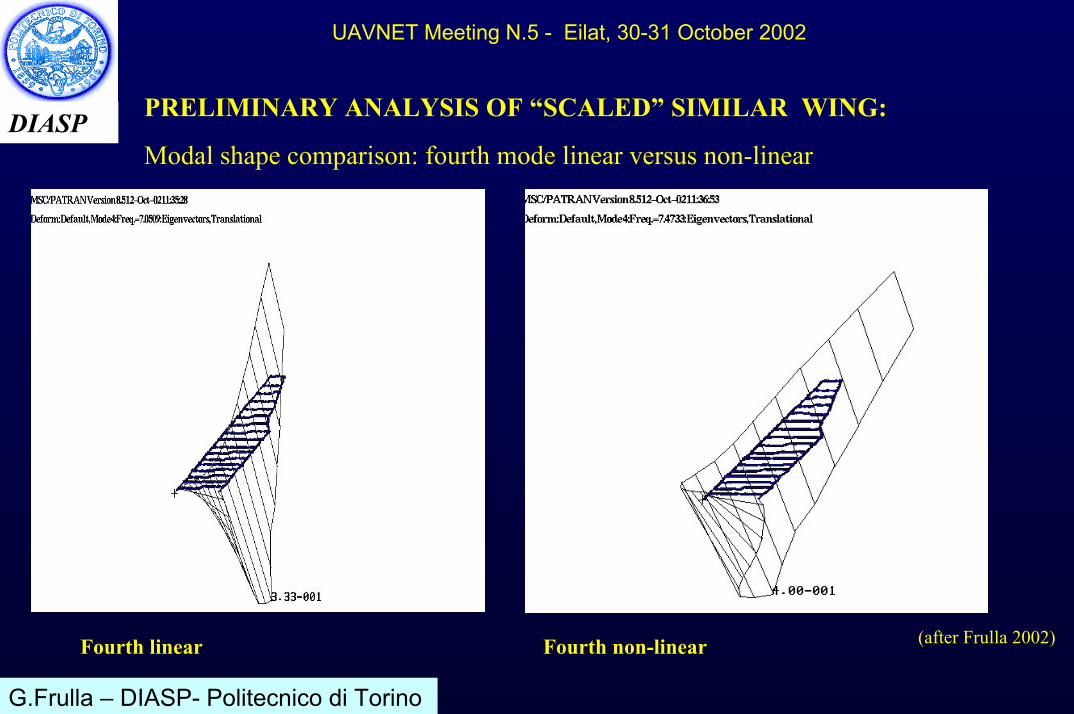
PRELIMINARY ANALYSIS OF “SCALED” SIMILAR WING:
Modal shape comparison: fourth mode linear versus non-linear
(after Frulla 2002)Fourth linear Fourth non-linear
G.Frulla – DIASP- Politecnico di Torino

DIASP
UAVNET Meeting N.5 - Eilat, 30-31 October 2002
PRELIMINARY ANALYSIS OF “SCALED” SIMILAR WING:
FLUTTER ANALYSYS: V-g plots linear
G.Frulla – DIASP- Politecnico di Torino (after Frulla 2002)
DIASP
UAVNET Meeting N.5 - Eilat, 30-31 October 2002
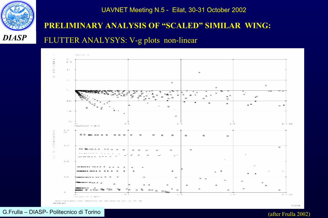
PRELIMINARY ANALYSIS OF “SCALED” SIMILAR WING:
FLUTTER ANALYSYS: V-g plots non-linear
G.Frulla – DIASP- Politecnico di Torino (after Frulla 2002)

DIASP
UAVNET Meeting N.5 - Eilat, 30-31 October 2002
FLUTTER CALCULATION FOR A SLENDER WING AIRCRAFT (Patil, Hodges, Cesnik 2001). The geometrical data are: chord/L=1/16, m=0.75kg/m. I=0.1kgm, GJ/EIf=0.5; EIlag/EIf=100 . First torsion/first flap freq.=13.86; firstlag/first flap freq.=14.13.
(frequencies behavior versus tip displacement - after Patil Hodges Cesznik 2001)

DIASP
UAVNET Meeting N.5 - Eilat, 30-31 October 2002
A significant reduction (up to 20%) in flutter speed is obtained with a tip deflection of about 0.1-0.15 of the half-span. Aeroelastic tailoring and a certain degree of opposite curvature in the wing can reduce this deleterious effect (down pre-curvature is limited by the ground clearance).
(flutter speed versus tip displacement - after Patil Hodges Cesznik 2001)

DIASP
UAVNET Meeting N.5 - Eilat, 30-31 October 2002
Whirl flutter ( propeller-nacelle):It is important to note that if the nacelle is rigid, and the aerodynamic is not present , the system (4-blade rotor) is always stable. Since the whirl mode produce some angle of attack changes, aerodynamic forces provide the mechanism of instability.
(figure 1, figure 2, after Reed 1985)

DIASP
UAVNET Meeting N.5 - Eilat, 30-31 October 2002
Dynamic coupling of propeller-nacelle system with the wing motions can alter the whirl flutter boundaries predicted by rigid wing assumption. The general trend is indicated with aerodynamic loads acting on propeller and wing.
(figure 4 - after Reed 1985)

DIASP
UAVNET Meeting N.5 - Eilat, 30-31 October 2002
The Dynamic stability of a suspended rigid rotor (without aerodynamic) was studied by the author in a specific application (advanced joined rotor) in order to point out some characteristic of the inertia inequalities and elastic component of the suspension.
0][][2][2][ 2
00=
+
Ω+
Ω+
γζ
ωγζ
γζ
γζ
KMJM&
&
&
&
&&
&&
)()(
)()()(;
)()(
10
2
10
10
10
2
0
γζ
γζγζ εεωKKKK
IIIA
IIII
IIKK
Si +−
=+
=+−
=++
=
G.Frulla – DIASP- Politecnico di Torino(after Frulla 2000)

DIASP
UAVNET Meeting N.5 - Eilat, 30-31 October 2002
Referring to unsymmetrical rigid rotor as in this case of two blades, L is the length of a blade, c,b the transversal dimensions and m the blade mass, the inertial parameters are:
2222
22
2222
22
)/(64/)2(14/1
)/(64/)2(14/1
LhLcbLc
LhLcbLcA
i +++−
=+++
+= ε
If the blades are slender the transversal dimension can be neglected obtaining:
Ai=ε
(Values different from unity refer to rotor with a distance between the rotor and the joint)
G.Frulla – DIASP- Politecnico di Torino(after Frulla 2000)

DIASP
UAVNET Meeting N.5 - Eilat, 30-31 October 2002
An elastically symmetric rotor (εs=0) is considered. Value of A=0.5 divides the region in two fields: for A less than 0.5 there are two critical velocities than include a unstable field. For A equal or higher than 0.5 there is only one critical velocity and the upper part of the plane is unstable.
G.Frulla – DIASP- Politecnico di Torino
(after Frulla 2000)

DIASP
UAVNET Meeting N.5 - Eilat, 30-31 October 2002
For rotors with elastic symmetry, the critical velocities are well defined, while for different elastic parameter other unstable fields appear. Two particular cases are reported : 1) A=0.2715, εi=0.234; 2) A=0.9 εi=0.9.
(after Frulla 2000) G.Frulla – DIASP- Politecnico di Torino

DIASPNew tendency in AEROSPACE: AAW Concept
• A new Air Force research project at NASA Dryden has been developing with the aim of taking an element of the Wright brothers into the new designed aircraft.
• This “back to the future” involves the Active Aeroelastic Wing concept (AAW) that is trying to use the elastic twist and warping of a wing to control the aircraft.
• Modern engineers have done everything possible to counteract such kind of deformations from physically stiffening the wings.
• Wings that typically twist in flight are thin and light with high aspect ratio providing good lift and drag characteristics. But they are overstressed. For this reason in the past the response to such kind of phenomena was to remove it.
• Researchers believe AAW concepts can be tailored to control wing twist at high speed and improve roll maneuvering perhaps to the point of eliminating the tail completely. The success of this new wing is connected to the overstress controlling.
UAVNET Meeting N.5 - Eilat, 30-31 October 2002
DIASP
UAVNET Meeting N.5 - Eilat, 30-31 October 2002
New tendency in AEROSPACE: AAW Concept (CONTINUATION)
• The AAW concept can provide a more high-aspect-ratio weight competitive wing and a more efficient one reducing fuel consumption.
• Some applications can involve future airplanes (HALE UAV – supersonic cruiser). The energy of the air is used as a motor to obtain a desired twist : the control surface will be only as tabs in order to initiate the expected effect. The aim of the design will be to use this characteristic instead of trying to overcome control surface losses due to elastic wing twist.
• Some expected figures says that an AAW wing can give a weight saving of about 25% if applied correctly.

UAVNET Meeting N.5 - Eilat, 30-31 October 2002 SHORT REFERENCE SUMMARY
•.Bisplinghoff, Ashley, Halfman : “Aeroelasticity”. Addison Wesley Pub. Comp. INC. 1955.• .Kolonay, : “Computational Aeroelasticity “, METU The applied Vehicle Technology Panel NATO-RTO , Ankara Turkey October 1-5 2001.• .Scanlan Rosenbaum :”Introduction to the study of aircraft vibration and flutter” . Macmillan Comp. . 1951.• .Cicala :”Comparison of theory with experiment in the phenomenon of wing flutter”, NACA TM 887 1939. • Prandtl : “Application of modern Hydrodynamics to aeronautics” NACA R.116. • .Dowell, Crawley and others “Modern course in Aeroelasticity”. Kluwer Ac. Pub. 1995. • . Bielawa :” Rotary wing structural dynamics and aeroelasticity”. AIAA Ed. Series. 1992.• .Milne Thompson : “Theoretical aerodynamics”, DOVER,1958.• .Chiocchia : “Principi di Aeroelasticità”, Levrotto e Bella, 1990.• .Wilson: “Active aeroelastic wing: a new/old twist on flight”, AEROSPACE America, September 2002.• .Da Silva, Hodges: “Effect of approximations on the static and dynamic response of a cantilever with a tip mass”.Int. J. Solids Structures Vol27, N.5, 1991. • .Reed III,: “Propeller-rotor whirl flutter: a state of the art review”. J. Sound Vib. , 4,(3), 1966.• .Song, Librescu, : “Free vibration of anisotropic composite thin-walled beams of closed cross-section contour”. J.Sound Vib. , 167(1), 1993.• Antona Frulla.”Cicala’s asymptotic approach to the linear shell theory”. Composite Structures 52(2001) 13-26.• Frulla PhD Thesis, 1999.• Frulla ,“Rigid rotor dynamic stability using Floquet theory”,Eur. J. Mech.A/ Solids, 19,2000.• Frulla , “HELIPLAT: Structural Analysis of High altitude very-long endurance solar powered platform for telecommunication and earth observation applications “, ICAS2002 Congress, 8-13 Sept., Toronto.• Frulla, “Aeroelastic behavior of simplified slender wings”. To be published . 2002.