![USB AUDIO INTERFACE...8Interruptor [INPUT 2 HI-Z] Activa o desactiva la impedancia de entrada (ON O/ OFF N). Active este interruptor si desea conectar instrumentos con impedancia alta,](https://static.fdocuments.us/doc/165x107/6077e1c783b0163efe0d1ded/usb-audio-interface-8interruptor-input-2-hi-z-activa-o-desactiva-la-impedancia.jpg)
Solving Difficult Cable Measurements -...
43
Slide #1 Let's talk about cable testing in this session. Cables are the most common devices, except for perhaps connectors, which may be considered as part of the cable. Virtually every system must have cabling to interconnect with other devices. There are many different considerations in selecting cables and in the related measurements to characterize them. Introduce yourself and the topic for the next 40 minutes. Inquire if there are any customers that are currently performing cable testing and determine the level of the audience. This section is a survey rather than a detailed discussion on cable testing. RF and MW Device Test Seminar 1993 Solving Difficult Cable Measurements Solving Difficult Cable Measurements 7-1
Transcript of Solving Difficult Cable Measurements -...
Slide #1
Let's talk about cable testing in this session. Cablesare the most common devices, except for perhapsconnectors, which may be considered as part of thecable. Virtually every system must have cabling tointerconnect with other devices. There are manydifferent considerations in selecting cables and in therelated measurements to characterize them.
Introduce yourself and the topic for the next 40
minutes. Inquire if there are any customers that are
currently performing cable testing and determine the
level of the audience. This section is a survey rather
than a detailed discussion on cable testing.
RF and MW Device Test Seminar 1993
Solving Difficult Cable Measurements
Solving Difficult Cable Measurements
7-1
Slide #2
This presentation is a brief overview of cables and thetrends within the industry.
We'll review the typical measurements that are used tospecify and characterize cables. More specifically, we will focus on Cable TV trunkcables and the structural return loss measurement. Twisted pair cables are widely used in computer LANinstallations and provide some additionalmeasurement issues.
Four main topics with the most emphasis on two
network analyzer measurements: SRL on coax and
swept measurements on twisted pair.
Microwave Instrument DivisionRF & MW Device Test Seminar0893 cabltest.pre
Agenda
Cable types and trends
Measurements
Coaxial Cables
Twisted Pair cables
Solving Difficult Cable Measurements
7-2
Slide #3
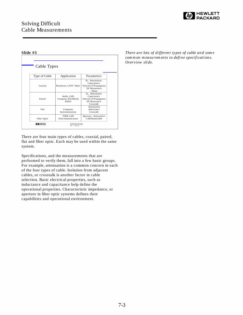
There are four main types of cables, coaxial, paired,flat and fiber optic. Each may be used within the samesystem.
Specifications, and the measurements that areperformed to verify them, fall into a few basic groups.For example, attenuation is a common concern in eachof the four types of cable. Isolation from adjacentcables, or crosstalk is another factor in cableselection. Basic electrical properties, such asinductance and capacitance help define theoperational properties. Characteristic impedance, oraperture in fiber optic systems defines theircapabilities and operational environment.
There are lots of different types of cable and some
common measurements to define specifications.
Overview slide.
Microwave Instrument DivisionRF & MW Device Test Seminar0893 cabltest.pre
Cable Types
Type of Cable Application Parameters
Coaxial Broadcast, CATV Video
Zc, Attenuation,Capacitance
Velocity of Propagation DC Reisistance
Delay
PairedAudio, LAN,
Computer EIA RS232, RS423
Zc, AttenuationCapacitance
Velocity of Propagation DC Resistance
Crosstalk
Flat Computer Instrumentation
Attenuation Inductance
Crosstalk
Fiber OpticFDDI, LAN
TelecommunicationAperture, Attenuation
-3 dB Bandwidth
Solving Difficult Cable Measurements
7-3
Slide #4
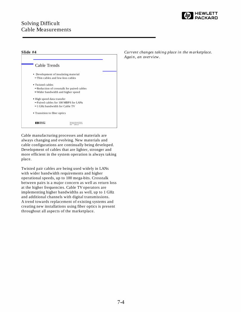
Cable manufacturing processes and materials arealways changing and evolving. New materials andcable configurations are continually being developed.Development of cables that are lighter, stronger andmore efficient in the system operation is always takingplace.
Twisted pair cables are being used widely in LANswith wider bandwidth requirements and higheroperational speeds, up to 100 mega-bits. Crosstalkbetween pairs is a major concern as well as return lossat the higher frequencies. Cable TV operators areimplementing higher bandwidths as well, up to 1 GHzand additional channels with digital transmissions.A trend towards replacement of existing systems andcreating new installations using fiber optics is presentthroughout all aspects of the marketplace.
Current changes taking place in the marketplace.
Again, an overview.
Microwave Instrument DivisionRF & MW Device Test Seminar0893 cabltest.pre
Cable Trends
Development of insulating materialThin cables and low-loss cables
Twisted cablesReduction of crosstalk for paired cablesWider bandwidth and higher speed
High speed data transferPaired cables for 100 MBPS for LANs1 GHz bandwidth for Cable TV
Transition to fiber optics
Solving Difficult Cable Measurements
7-4
Slide #5
Let's now discuss the types of measurements that areperformed on cables by both the manufacturers andthe end-users. There seem to be three generalcategories; swept frequency measurements, twistedpair characterization and the measurements of thebasic electrical properties. Many specifications aregiven at specific frequencies. The measurements mayalso be swept in frequency but specified at only a fewrepresentative frequencies. As always withspecifications, there is an attempt to standardize onmeasurements. Different types of test equipmentmay be used to make the same measurements.
Twisted pair measurements are a series ofmeasurements that are used to define the relationshipsof the pairs to each other and to other pairs within thecable.
Physical measurements are those measurements thatdefine the basic electrical properties of the cable; e.g.resistance or capacitance.
Topic slide for the next three slides. This is my
attempt to group the types of measurements and
there is some overlap. In this section the focus is on
swept frequency measurements.
Microwave Instrument DivisionRF & MW Device Test Seminar0893 cabltest.pre
Types of Cable Measurements
Swept frequency
Twisted pair
Physical characteristics
Solving Difficult Cable Measurements
7-5
Slide #6
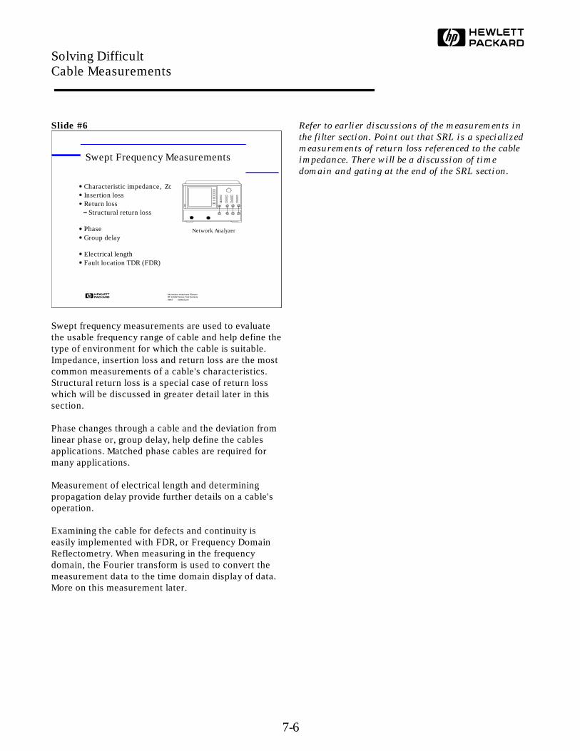
Swept frequency measurements are used to evaluatethe usable frequency range of cable and help define thetype of environment for which the cable is suitable.Impedance, insertion loss and return loss are the mostcommon measurements of a cable's characteristics.Structural return loss is a special case of return losswhich will be discussed in greater detail later in thissection.
Phase changes through a cable and the deviation fromlinear phase or, group delay, help define the cablesapplications. Matched phase cables are required formany applications.
Measurement of electrical length and determiningpropagation delay provide further details on a cable'soperation.
Examining the cable for defects and continuity iseasily implemented with FDR, or Frequency DomainReflectometry. When measuring in the frequencydomain, the Fourier transform is used to convert themeasurement data to the time domain display of data.More on this measurement later.
Refer to earlier discussions of the measurements in
the filter section. Point out that SRL is a specialized
measurements of return loss referenced to the cable
impedance. There will be a discussion of time
domain and gating at the end of the SRL section.
Microwave Instrument DivisionRF & MW Device Test Seminar0893 cabltest.pre
Swept Frequency Measurements
Characteristic impedance, ZcInsertion lossReturn loss
Structural return loss
PhaseGroup delay
Electrical lengthFault location TDR (FDR)
Network Analyzer
Solving Difficult Cable Measurements
7-6
Slide #7
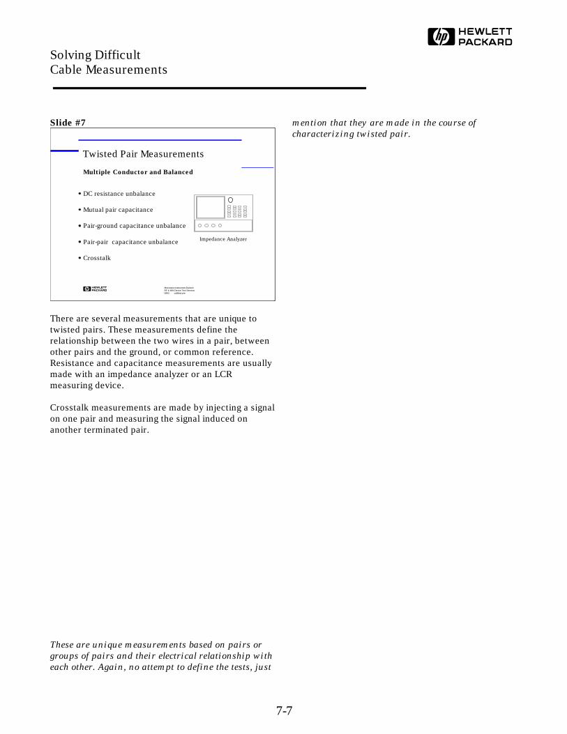
There are several measurements that are unique totwisted pairs. These measurements define therelationship between the two wires in a pair, betweenother pairs and the ground, or common reference.Resistance and capacitance measurements are usuallymade with an impedance analyzer or an LCRmeasuring device.
Crosstalk measurements are made by injecting a signalon one pair and measuring the signal induced onanother terminated pair.
These are unique measurements based on pairs or
groups of pairs and their electrical relationship with
each other. Again, no attempt to define the tests, just
mention that they are made in the course of
characterizing twisted pair.
Microwave Instrument DivisionRF & MW Device Test Seminar0893 cabltest.pre
Twisted Pair Measurements
DC resistance unbalance
Mutual pair capacitance
Pair-ground capacitance unbalance
Pair-pair capacitance unbalance
Crosstalk
Impedance Analyzer
Multiple Conductor and Balanced
Solving Difficult Cable Measurements
7-7
Slide #8
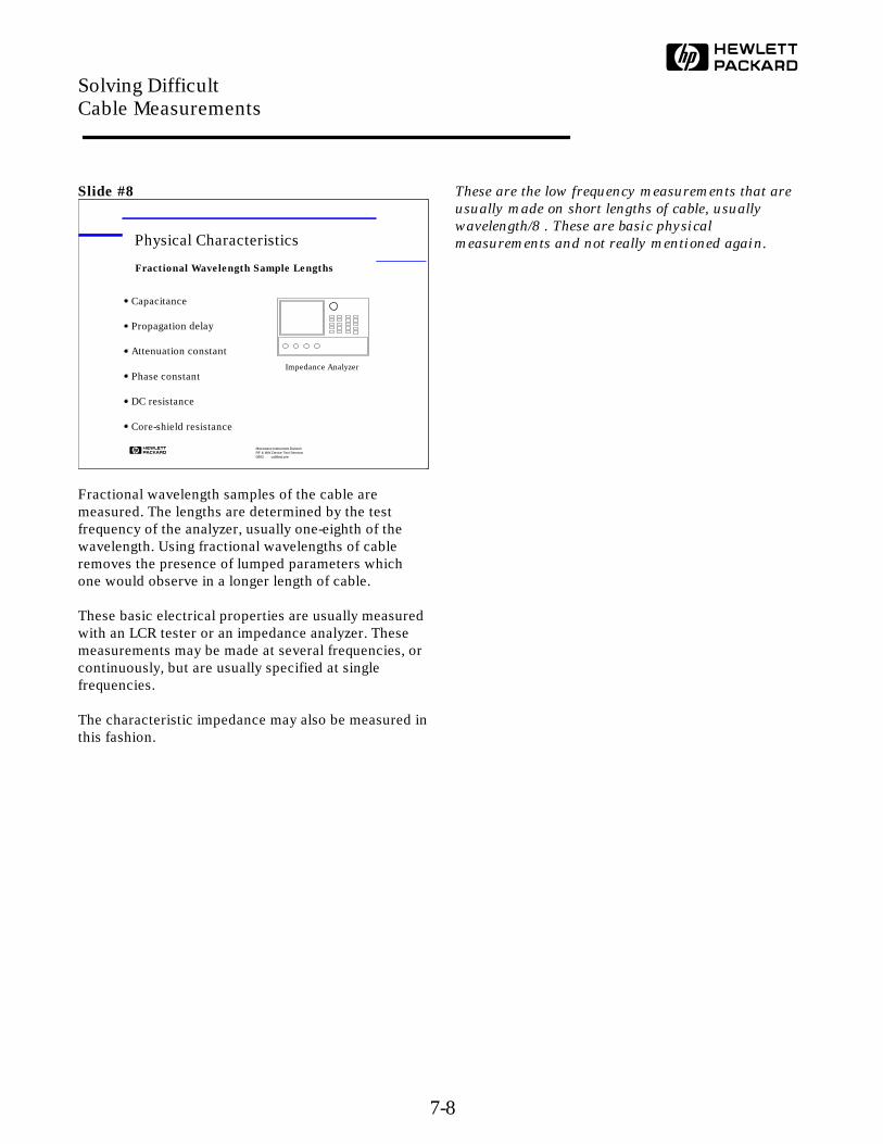
Fractional wavelength samples of the cable aremeasured. The lengths are determined by the testfrequency of the analyzer, usually one-eighth of thewavelength. Using fractional wavelengths of cableremoves the presence of lumped parameters whichone would observe in a longer length of cable.
These basic electrical properties are usually measuredwith an LCR tester or an impedance analyzer. Thesemeasurements may be made at several frequencies, orcontinuously, but are usually specified at singlefrequencies.
The characteristic impedance may also be measured inthis fashion.
These are the low frequency measurements that are
usually made on short lengths of cable, usually
wavelength/8 . These are basic physical
measurements and not really mentioned again.
Microwave Instrument DivisionRF & MW Device Test Seminar0893 cabltest.pre
Physical Characteristics
Capacitance
Propagation delay
Attenuation constant
Phase constant
DC resistance
Core-shield resistance
Impedance Analyzer
Fractional Wavelength Sample Lengths
Solving Difficult Cable Measurements
7-8
Slide #9
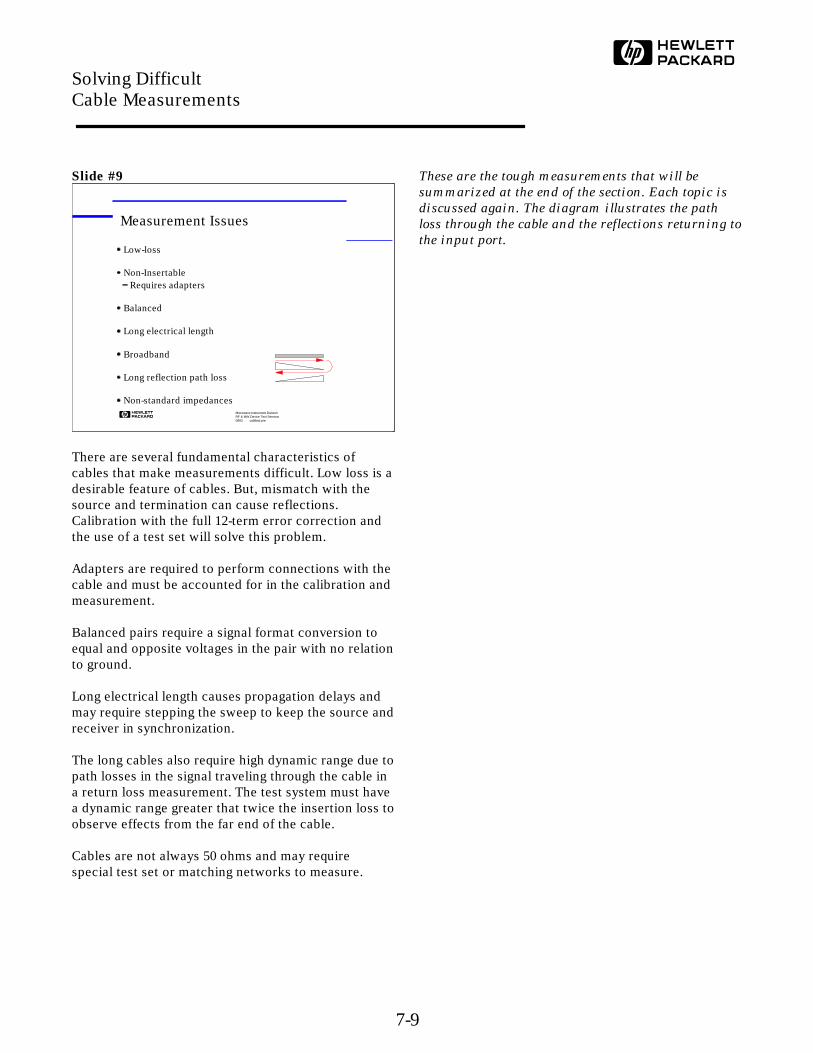
There are several fundamental characteristics ofcables that make measurements difficult. Low loss is adesirable feature of cables. But, mismatch with thesource and termination can cause reflections.Calibration with the full 12-term error correction andthe use of a test set will solve this problem. Adapters are required to perform connections with thecable and must be accounted for in the calibration andmeasurement.
Balanced pairs require a signal format conversion toequal and opposite voltages in the pair with no relationto ground.
Long electrical length causes propagation delays andmay require stepping the sweep to keep the source andreceiver in synchronization.
The long cables also require high dynamic range due topath losses in the signal traveling through the cable ina return loss measurement. The test system must havea dynamic range greater that twice the insertion loss toobserve effects from the far end of the cable.
Cables are not always 50 ohms and may requirespecial test set or matching networks to measure.
These are the tough measurements that will be
summarized at the end of the section. Each topic is
discussed again. The diagram illustrates the path
loss through the cable and the reflections returning to
the input port.
Microwave Instrument DivisionRF & MW Device Test Seminar0893 cabltest.pre
Measurement Issues
Low-loss
Non-InsertableRequires adapters
Balanced
Long electrical length
Broadband
Long reflection path loss
Non-standard impedances
Solving Difficult Cable Measurements
7-9

Slide #10
Let's examine the measurements on cable TV cables indetail. The same concerns and measurements wouldalso apply to and long cable run; e.g. antenna feeds.
Higher bandwidths are evolving and are affecting thetest requirements and test equipment needs. Higherfrequency testing will lead to more stringentrequirements in test equipment.
Long runs of cable require higher dynamic range forboth insertion loss and reflection measurements.
Insertion losses increase with higher frequencies.
Electrical delay must be taken into consideration dueto long lengths.
This slide describes the typical measurement
environment for reels of cable TV cables. Long cables
mean big losses. There's a table of losses per cable
reel on the next slide. Slow sweeps or step mode are
used to compensate for the electrical delay through
the cable.
Microwave Instrument DivisionRF & MW Device Test Seminar0893 cabltest.pre
Cable TV Cables
Higher Bandwidths400 MHz to 750 MHz to 1 GHz
Long lengths of cables
Insertion loss
Electrical delay
Solving Difficult Cable Measurements
7-10
Slide #11
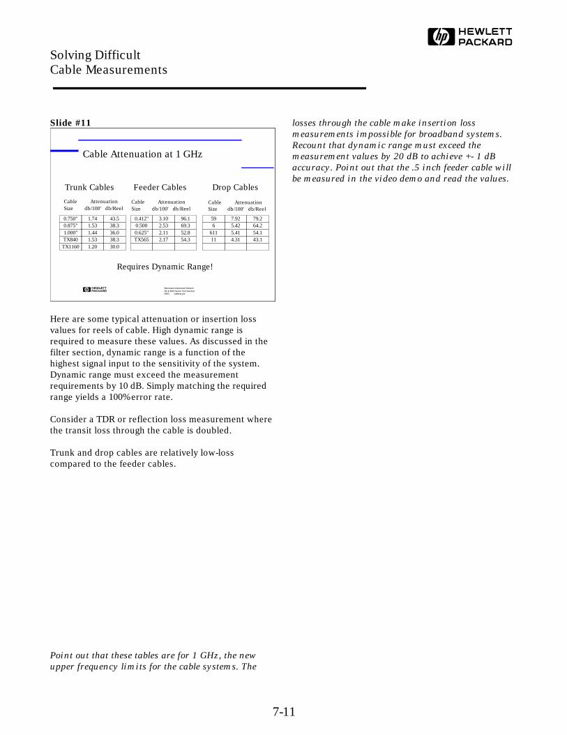
Here are some typical attenuation or insertion lossvalues for reels of cable. High dynamic range isrequired to measure these values. As discussed in thefilter section, dynamic range is a function of thehighest signal input to the sensitivity of the system.Dynamic range must exceed the measurementrequirements by 10 dB. Simply matching the requiredrange yields a 100% error rate.
Consider a TDR or reflection loss measurement wherethe transit loss through the cable is doubled.
Trunk and drop cables are relatively low-losscompared to the feeder cables.
Point out that these tables are for 1 GHz, the new
upper frequency limits for the cable systems. The
losses through the cable make insertion loss
measurements impossible for broadband systems.
Recount that dynamic range must exceed the
measurement values by 20 dB to achieve +- 1 dB
accuracy. Point out that the .5 inch feeder cable will
be measured in the video demo and read the values.
Microwave Instrument DivisionRF & MW Device Test Seminar0893 cabltest.pre
Cable Attenuation at 1 GHz
0.750" 1.74 43.50.875" 1.53 38.31.000" 1.44 36.0TX840 1.53 38.3
TX1160 1.20 30.0
Trunk Cables
Cable AttenuationSize db/100' db/Reel
59 7.92 79.26 5.42 64.2
611 5.41 54.111 4.31 43.1
Drop Cables
Cable AttenuationSize db/100' db/Reel
0.412" 3.10 96.10.500 2.53 69.30.625" 2.11 52.8TX565 2.17 54.3
Feeder Cables
Cable AttenuationSize db/100' db/Reel
Requires Dynamic Range!
Solving Difficult Cable Measurements
7-11
Slide #12
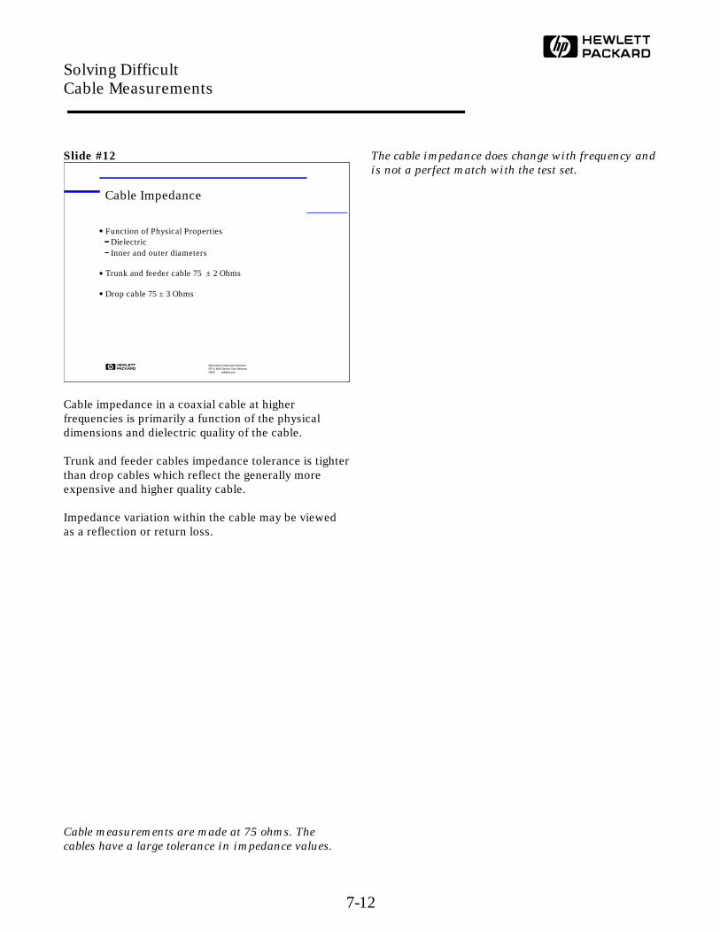
Cable impedance in a coaxial cable at higherfrequencies is primarily a function of the physicaldimensions and dielectric quality of the cable.
Trunk and feeder cables impedance tolerance is tighterthan drop cables which reflect the generally moreexpensive and higher quality cable.
Impedance variation within the cable may be viewedas a reflection or return loss.
Cable measurements are made at 75 ohms. The
cables have a large tolerance in impedance values.
The cable impedance does change with frequency and
is not a perfect match with the test set.
Microwave Instrument DivisionRF & MW Device Test Seminar0893 cabltest.pre
Cable Impedance
Function of Physical PropertiesDielectricInner and outer diameters
Trunk and feeder cable 75 ± 2 Ohms
Drop cable 75 ± 3 Ohms
Solving Difficult Cable Measurements
7-12

Slide #13
This measurement is easily made on one end of acable. The amount of signal that is reflected iscompared to the signal that is injected.
Any discontinuities or physical variations are observedas a reflected signal. Impedance variations also appearas discontinuities as each change reflects power.
Connectors and the cable interface may also generatereflections. Connector quality and match may be alsoexamined.
Reflection loss measurement is just as discussed in
the earlier sections.
Microwave Instrument DivisionRF & MW Device Test Seminar0893 cabltest.pre
Return Loss Measurement
Observe discontinuities as reflections
Measure Impedance variations
Evaluate connectors and cable
LOAD
Incident
ReflectedSource
Cable Reel
Solving Difficult Cable Measurements
7-13
Slide #14
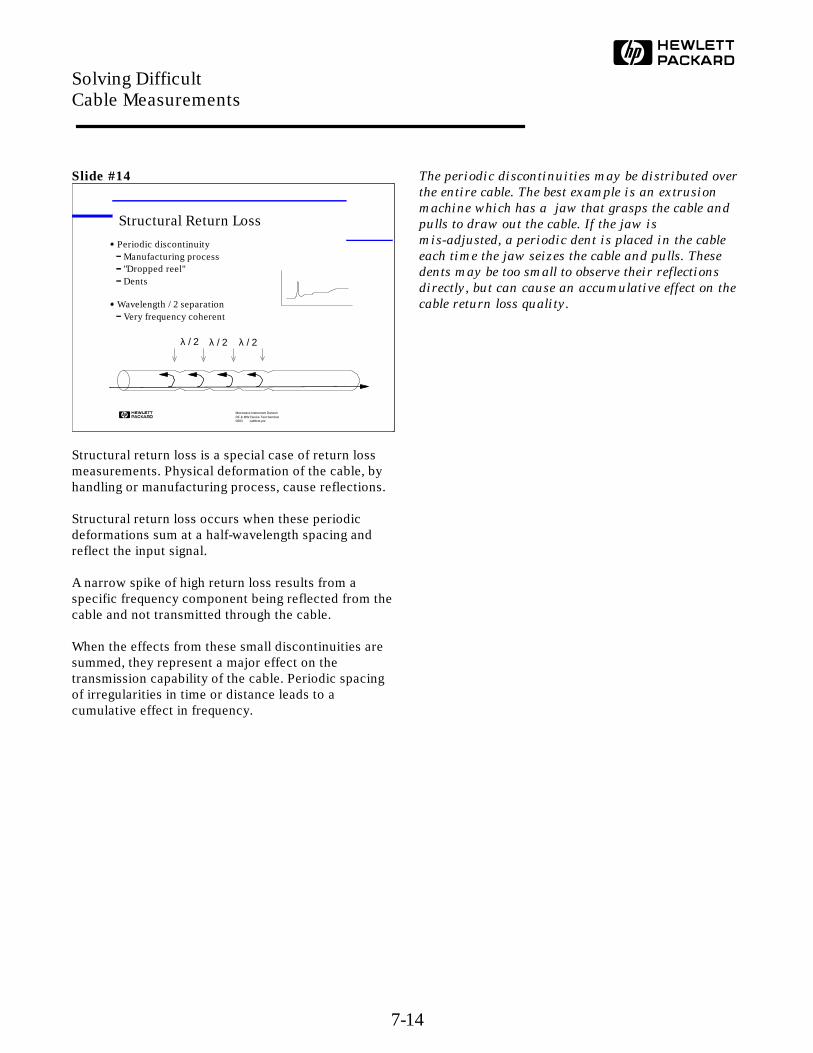
Structural return loss is a special case of return lossmeasurements. Physical deformation of the cable, byhandling or manufacturing process, cause reflections.
Structural return loss occurs when these periodicdeformations sum at a half-wavelength spacing andreflect the input signal.
A narrow spike of high return loss results from aspecific frequency component being reflected from thecable and not transmitted through the cable.
When the effects from these small discontinuities aresummed, they represent a major effect on thetransmission capability of the cable. Periodic spacingof irregularities in time or distance leads to acumulative effect in frequency.
The periodic discontinuities may be distributed over
the entire cable. The best example is an extrusion
machine which has a jaw that grasps the cable and
pulls to draw out the cable. If the jaw is
mis-adjusted, a periodic dent is placed in the cable
each time the jaw seizes the cable and pulls. These
dents may be too small to observe their reflections
directly, but can cause an accumulative effect on the
cable return loss quality.
Microwave Instrument DivisionRF & MW Device Test Seminar0893 cabltest.pre
Periodic discontinuityManufacturing process"Dropped reel"Dents
Wavelength / 2 separationVery frequency coherent
Structural Return Loss
λ / 2 λ / 2 λ / 2
Solving Difficult Cable Measurements
7-14
Slide #15
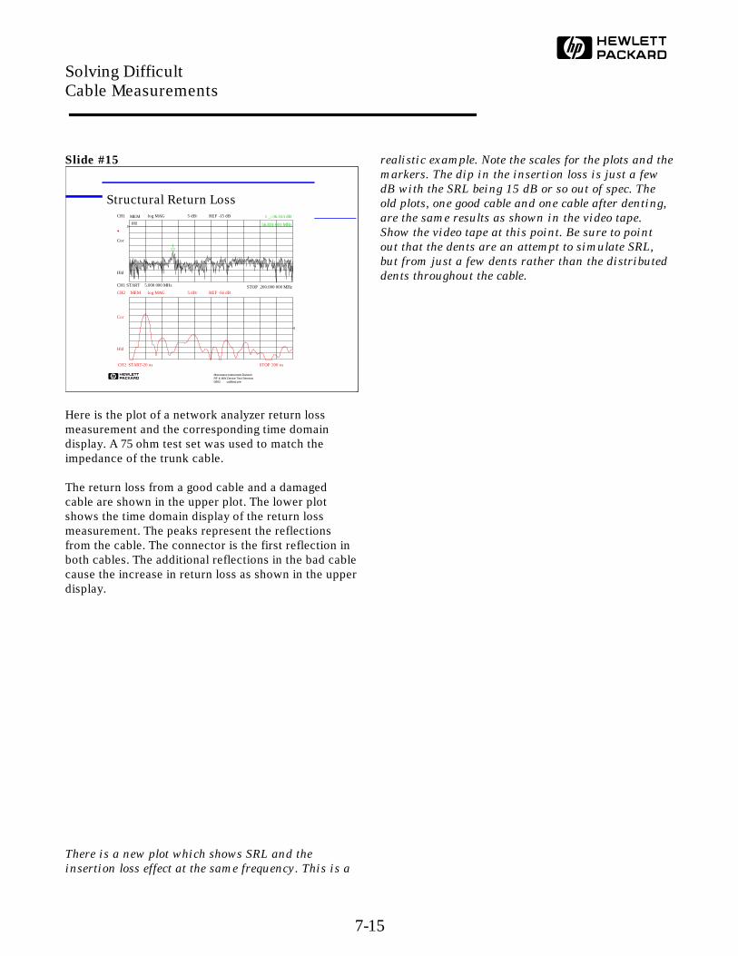
Here is the plot of a network analyzer return lossmeasurement and the corresponding time domaindisplay. A 75 ohm test set was used to match theimpedance of the trunk cable.
The return loss from a good cable and a damagedcable are shown in the upper plot. The lower plotshows the time domain display of the return lossmeasurement. The peaks represent the reflectionsfrom the cable. The connector is the first reflection inboth cables. The additional reflections in the bad cablecause the increase in return loss as shown in the upperdisplay.
There is a new plot which shows SRL and the
insertion loss effect at the same frequency. This is a
realistic example. Note the scales for the plots and the
markers. The dip in the insertion loss is just a few
dB with the SRL being 15 dB or so out of spec. The
old plots, one good cable and one cable after denting,
are the same results as shown in the video tape.
Show the video tape at this point. Be sure to point
out that the dents are an attempt to simulate SRL,
but from just a few dents rather than the distributed
dents throughout the cable.
Microwave Instrument DivisionRF & MW Device Test Seminar0893 cabltest.pre
Structural Return LossCH1 MEM log MAG 5 dB/ REF -15 dB
CH1 START 5.000 000 MHz STOP 200.000 000 MHz
*
Cor
Hld
*
1
1 _:-36.163 dB
56.831 001 MHz
CH2 MEM log MAG REF -56 dB5 dB/
CH2 START-20 ns STOP 200 ns
Cor
Hld
Solving Difficult Cable Measurements
7-15

Slide #16
Structural return loss measurements were originallymade with a variable bridge, a sweeper and a detector.The impedance of the cable is matched and measured,by adjusting the bridge for a minimum return loss andreading the value from the bridge dial. Cableimpedance variation may also be eliminated byadjusting the bridge.
Once a signal level is observed, the switch is thrownand the attenuator adjusted to match the signal level.Subtracting the attenuator setting from the sourcelevel determines the signal level being measured.
This manual measurement requires a skilled operator.
This is the original and most common measurement
setup for SRL on cables. Many customers still use
this system. This is the grease pencil world, where
you adjust an attenuator to match a level on the
display.
Microwave Instrument DivisionRF & MW Device Test Seminar0893 cabltest.pre
Variable Bridge Test Setup
75 Ohm
Display
VariableAttenuators
Calibrate
Measure
SweepGenerator
VariableBridge
Test Port
Cable Reel
Solving Difficult Cable Measurements
7-16
Slide #17
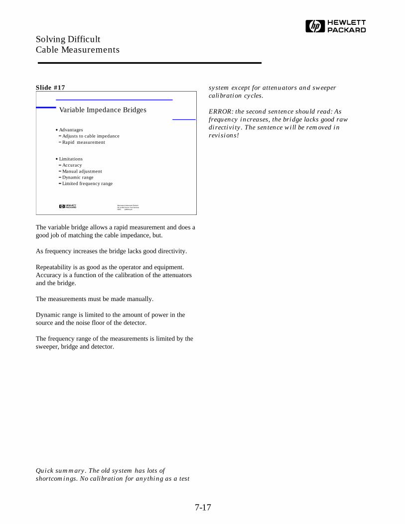
The variable bridge allows a rapid measurement and does agood job of matching the cable impedance, but.
As frequency increases the bridge lacks good directivity.
Repeatability is as good as the operator and equipment. Accuracy is a function of the calibration of the attenuatorsand the bridge.
The measurements must be made manually.
Dynamic range is limited to the amount of power in thesource and the noise floor of the detector.
The frequency range of the measurements is limited by thesweeper, bridge and detector.
Quick summary. The old system has lots of
shortcomings. No calibration for anything as a test
system except for attenuators and sweeper
calibration cycles.
ERROR: the second sentence should read: As
frequency increases, the bridge lacks good raw
directivity. The sentence will be removed in
revisions!
Microwave Instrument DivisionRF & MW Device Test Seminar0893 cabltest.pre
Variable Impedance Bridges
AdvantagesAdjusts to cable impedanceRapid measurement
LimitationsAccuracyManual adjustmentDynamic rangeLimited frequency range
Solving Difficult Cable Measurements
7-17
Slide #18
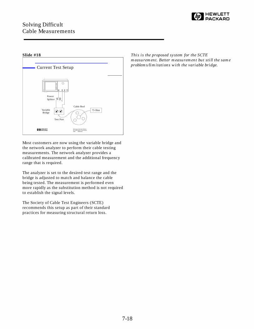
Most customers are now using the variable bridge andthe network analyzer to perform their cable testingmeasurements. The network analyzer provides acalibrated measurement and the additional frequencyrange that is required.
The analyzer is set to the desired test range and thebridge is adjusted to match and balance the cablebeing tested. The measurement is performed evenmore rapidly as the substitution method is not requiredto establish the signal levels.
The Society of Cable Test Engineers (SCTE)recommends this setup as part of their standardpractices for measuring structural return loss.
This is the proposed system for the SCTE
measurement. Better measurement but still the same
problems/limitations with the variable bridge.
Microwave Instrument DivisionRF & MW Device Test Seminar0893 cabltest.pre
Current Test Setup
75 OhmVariableBridge
Test Port
Cable Reel
PowerSplitter
Solving Difficult Cable Measurements
7-18

Slide #19
The network analyzer adds the needed dynamic rangeand a calibrated measurement to the system, but thelimitations of the variable bridge still affect themeasurement. The directivity, repeatability andaccuracy of the variable bridge technique is limited.
The bridge is usually varied to match the cableimpedance. The bridge may be calibrated to a fixedstandard, but the measurement is influenced byadjusting the bridge. Resisting the urge to adjust thebridge is necessary to obtain a good measurement.Even minor adjustments, "tweaks", can significantlyaffect the measurement results and cause the cable topass the test requirements.
The system can be calibrated, but as soon as you
tweak the bridge, the CAL is gone! This is the current
solution and may be contested by the audience.
Focus on calibration of the test set. New title on slide
to identify the variable bridge solution.
Microwave Instrument DivisionRF & MW Device Test Seminar0893 cabltest.pre
Network Analyzer
AdvantagesMinimize cable mismatchRapid measurementWider frequency range
LimitationsAccuracyManual adjustment
Solving Difficult Cable Measurements
7-19
Slide #20
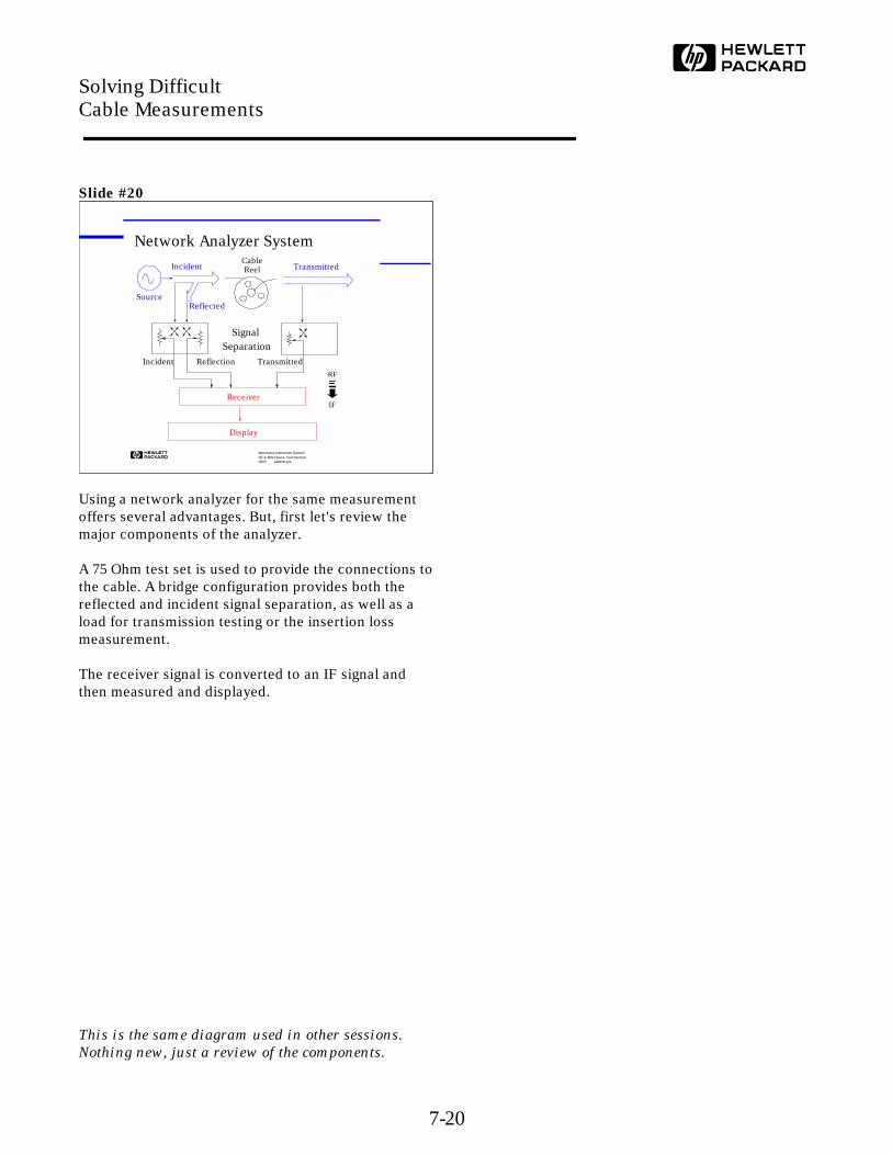
Using a network analyzer for the same measurementoffers several advantages. But, first let's review themajor components of the analyzer.
A 75 Ohm test set is used to provide the connections tothe cable. A bridge configuration provides both thereflected and incident signal separation, as well as aload for transmission testing or the insertion lossmeasurement.
The receiver signal is converted to an IF signal andthen measured and displayed.
This is the same diagram used in other sessions.
Nothing new, just a review of the components.
Microwave Instrument DivisionRF & MW Device Test Seminar0893 cabltest.pre
Network Analyzer System
Receiver
Display
Reflection TransmittedIncident
Incident
Reflected
Transmitted
SignalSeparation
Source
RF
IF
Cable Reel
Solving Difficult Cable Measurements
7-20
Slide #21
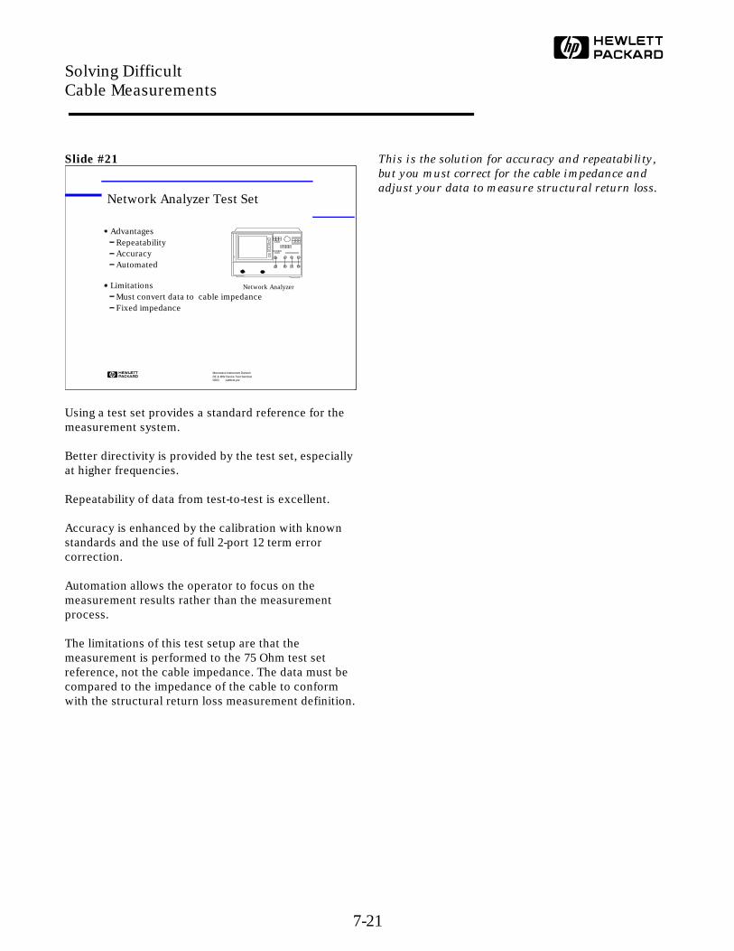
Using a test set provides a standard reference for themeasurement system.
Better directivity is provided by the test set, especiallyat higher frequencies.
Repeatability of data from test-to-test is excellent.
Accuracy is enhanced by the calibration with knownstandards and the use of full 2-port 12 term errorcorrection.
Automation allows the operator to focus on themeasurement results rather than the measurementprocess.
The limitations of this test setup are that themeasurement is performed to the 75 Ohm test setreference, not the cable impedance. The data must becompared to the impedance of the cable to conformwith the structural return loss measurement definition.
This is the solution for accuracy and repeatability,
but you must correct for the cable impedance and
adjust your data to measure structural return loss.
Microwave Instrument DivisionRF & MW Device Test Seminar0893 cabltest.pre
Network Analyzer Test Set
AdvantagesRepeatabilityAccuracyAutomated
LimitationsMust convert data to cable impedanceFixed impedance
Network Analyzer
Solving Difficult Cable Measurements
7-21
Slide #22
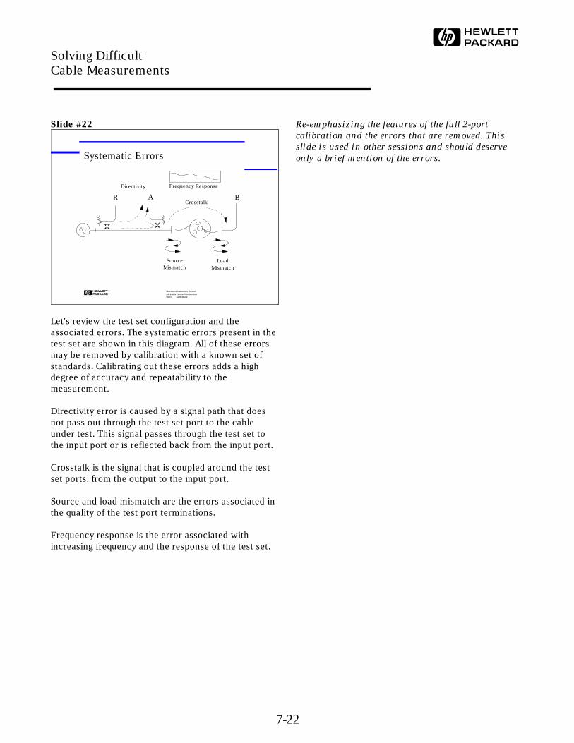
Let's review the test set configuration and theassociated errors. The systematic errors present in thetest set are shown in this diagram. All of these errorsmay be removed by calibration with a known set ofstandards. Calibrating out these errors adds a highdegree of accuracy and repeatability to themeasurement.
Directivity error is caused by a signal path that doesnot pass out through the test set port to the cableunder test. This signal passes through the test set tothe input port or is reflected back from the input port.
Crosstalk is the signal that is coupled around the testset ports, from the output to the input port.
Source and load mismatch are the errors associated inthe quality of the test port terminations.
Frequency response is the error associated withincreasing frequency and the response of the test set.
Re-emphasizing the features of the full 2-port
calibration and the errors that are removed. This
slide is used in other sessions and should deserve
only a brief mention of the errors.
Microwave Instrument DivisionRF & MW Device Test Seminar0893 cabltest.pre
Systematic Errors
AR BCrosstalk
Frequency Response
SourceMismatch
LoadMismatch
Directivity
Solving Difficult Cable Measurements
7-22
Slide #23
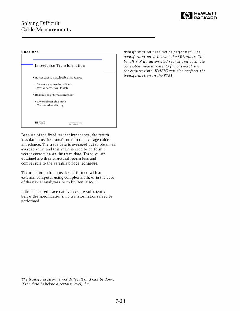
Because of the fixed test set impedance, the returnloss data must be transformed to the average cableimpedance. The trace data is averaged out to obtain anaverage value and this value is used to perform avector correction on the trace data. These valuesobtained are then structural return loss andcomparable to the variable bridge technique.
The transformation must be performed with anexternal computer using complex math, or in the caseof the newer analyzers, with built-in IBASIC .
If the measured trace data values are sufficientlybelow the specifications, no transformations need beperformed.
The transformation is not difficult and can be done.
If the data is below a certain level, the
transformation need not be performed. The
transformation will lower the SRL value. The
benefits of an automated search and accurate,
consistent measurements far outweigh the
conversion time. IBASIC can also perform the
transformation in the 8751.
Microwave Instrument DivisionRF & MW Device Test Seminar0893 cabltest.pre
Impedance Transformation
Adjust data to match cable impedance
Measure average impedanceVector correction to data
Requires an external controller
External complex math Corrects data display
Solving Difficult Cable Measurements
7-23

Slide #24
As mentioned earlier, time domain gating may be usedto examine individual responses from the cable undertest. The sums of the individual components mayobscure the device being examined. For example, athigher frequencies a poorly fitting slip-on connectormay cause a larger reflection than the cable. The cablemay be viewed independently from the connector bygating and viewing only the cable response.
Underlying signals which are masked may now beviewed.
Refer to the earlier discussions about SAW filter
measurements in the filters section.
Microwave Instrument DivisionRF & MW Device Test Seminar0893 cabltest.pre
Time Domain Gating
Examine or remove response from connector
Reduce reflections
Increase resolution
View cable response only
Solving Difficult Cable Measurements
7-24

Slide #25
The traces shown here illustrate the effects of timedomain gating. The desired response is enclosedwithin the gates in the time domain display. The returnloss data is modified to display only the signalsselected in the time domain trace. This capabilityallows us to effectively remove undesirable reflectionsfrom the connector. We can then measure the cableand ignore the effects from the connector.
The upper trace shows the return loss measurement oftwo cables, one with reflections from a bad connector.By removing the reflections from the connector, thesecond trace reveals more detail about the cablereflections.
The first reflection in the time domain display , theconnector, is gated out, i.e. the gate is set around all ofthe other reflections except the one from theconnector.
Connector and impedance mismatches, and other
major anomalies may be ignored or bypassed with
this gating.
Microwave Instrument DivisionRF & MW Device Test Seminar0893 cabltest.pre
Time Domain GatingCH1 RFL&M log MAG 5 dB/ REF -35 dB
CH1 START 5.000 000 MHz STOP 200.000 000 MHz
*
Cor
Hld
*
log MAG
CH2 RFL&M REF -56 dB5 dB/
STOP 500 ns
Gat
Cor
Hld
CH2 START 0 s
1
Solving Difficult Cable Measurements
7-25
Slide #26
Let's now leave the coaxial cable discussion andexamine the measurements which are performed ontwisted pair cables and the techniques required tomake those measurements.
This concludes the coaxial section. Questions or
comments? Now on to twisted pairs. Breakpoint.
Microwave Instrument DivisionRF & MW Device Test Seminar0893 cabltest.pre
Agenda
Cable types and trends
Measurements
Coaxial Cables
Twisted Pair cables
Solving Difficult Cable Measurements
7-26
Slide #27
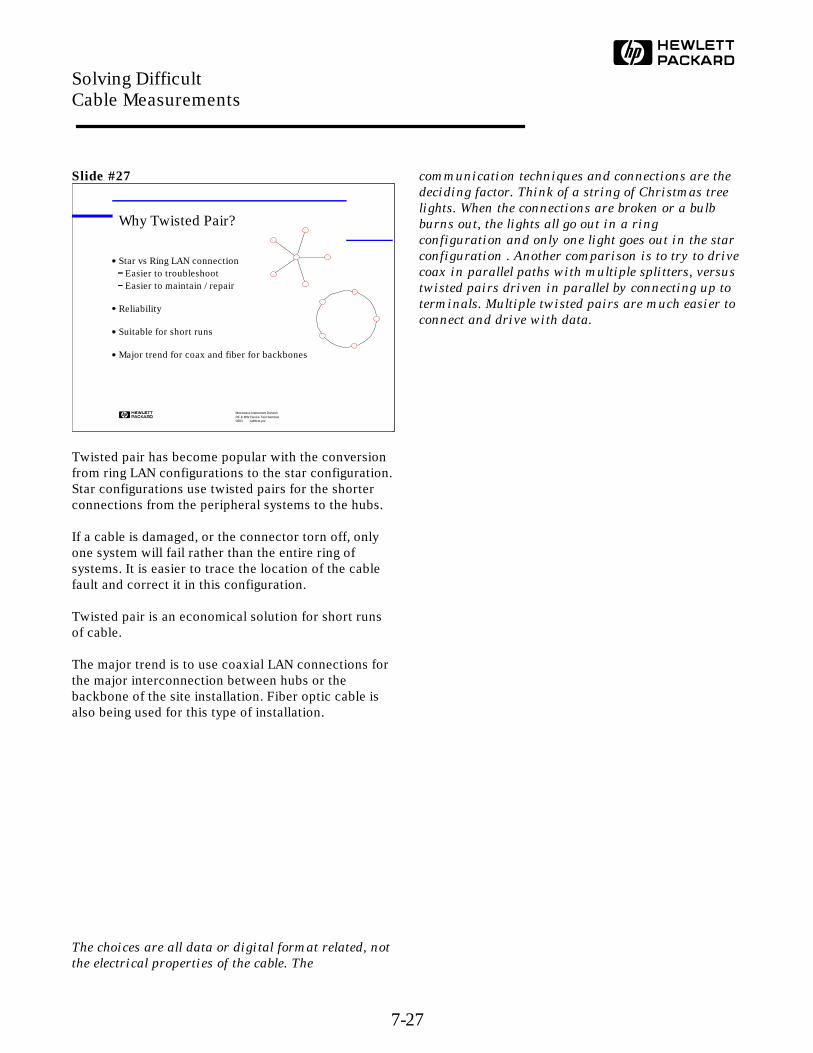
Twisted pair has become popular with the conversionfrom ring LAN configurations to the star configuration.Star configurations use twisted pairs for the shorterconnections from the peripheral systems to the hubs.
If a cable is damaged, or the connector torn off, onlyone system will fail rather than the entire ring ofsystems. It is easier to trace the location of the cablefault and correct it in this configuration.
Twisted pair is an economical solution for short runsof cable.
The major trend is to use coaxial LAN connections forthe major interconnection between hubs or thebackbone of the site installation. Fiber optic cable isalso being used for this type of installation.
The choices are all data or digital format related, not
the electrical properties of the cable. The
communication techniques and connections are the
deciding factor. Think of a string of Christmas tree
lights. When the connections are broken or a bulb
burns out, the lights all go out in a ring
configuration and only one light goes out in the star
configuration . Another comparison is to try to drive
coax in parallel paths with multiple splitters, versus
twisted pairs driven in parallel by connecting up to
terminals. Multiple twisted pairs are much easier to
connect and drive with data.
Microwave Instrument DivisionRF & MW Device Test Seminar0893 cabltest.pre
Why Twisted Pair?
Star vs Ring LAN connectionEasier to troubleshootEasier to maintain / repair
Reliability
Suitable for short runs
Major trend for coax and fiber for backbones
Solving Difficult Cable Measurements
7-27
Slide #28
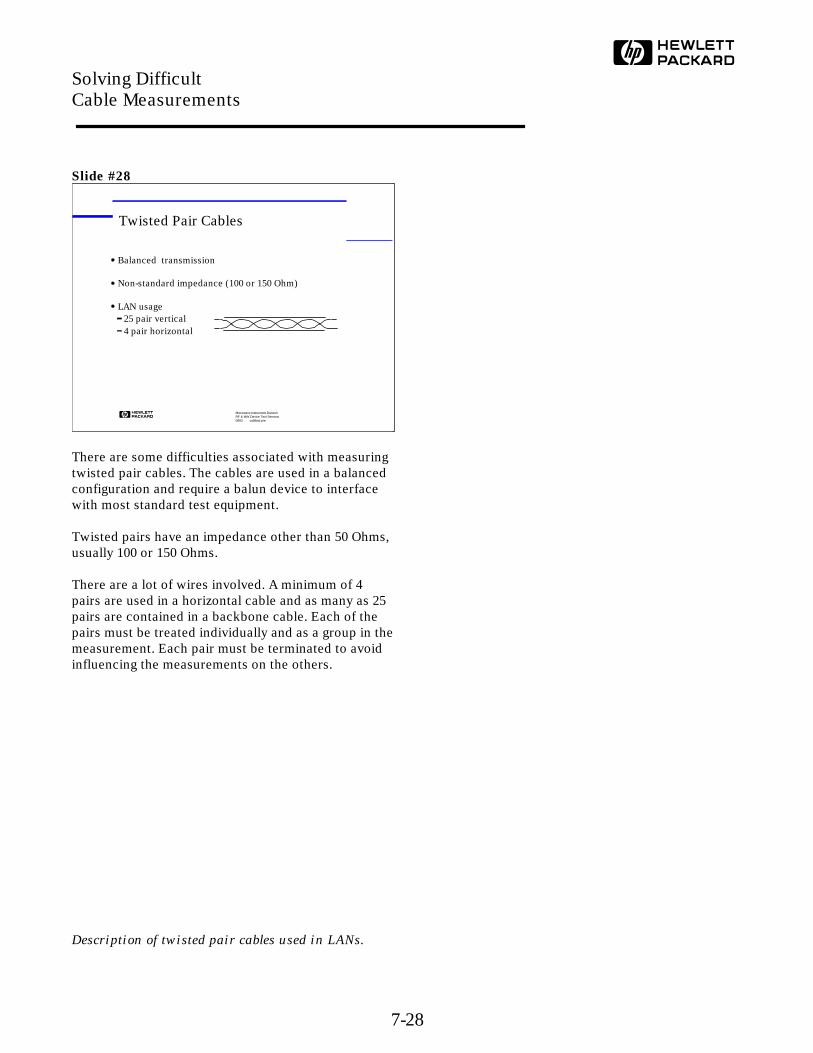
There are some difficulties associated with measuringtwisted pair cables. The cables are used in a balancedconfiguration and require a balun device to interfacewith most standard test equipment.
Twisted pairs have an impedance other than 50 Ohms,usually 100 or 150 Ohms.
There are a lot of wires involved. A minimum of 4pairs are used in a horizontal cable and as many as 25pairs are contained in a backbone cable. Each of thepairs must be treated individually and as a group in themeasurement. Each pair must be terminated to avoidinfluencing the measurements on the others.
Description of twisted pair cables used in LANs.
Microwave Instrument DivisionRF & MW Device Test Seminar0893 cabltest.pre
Twisted Pair Cables
Balanced transmission
Non-standard impedance (100 or 150 Ohm)
LAN usage25 pair vertical4 pair horizontal
Solving Difficult Cable Measurements
7-28
Slide #29
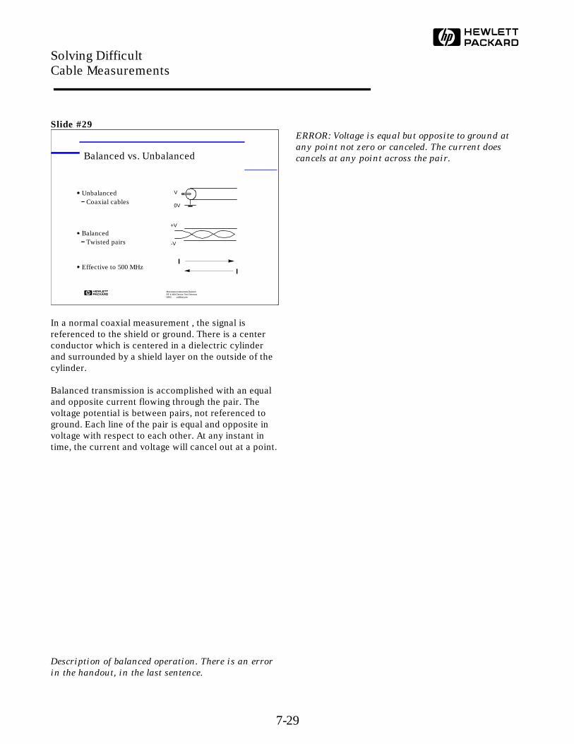
In a normal coaxial measurement , the signal isreferenced to the shield or ground. There is a centerconductor which is centered in a dielectric cylinderand surrounded by a shield layer on the outside of thecylinder.
Balanced transmission is accomplished with an equaland opposite current flowing through the pair. Thevoltage potential is between pairs, not referenced toground. Each line of the pair is equal and opposite involtage with respect to each other. At any instant intime, the current and voltage will cancel out at a point.
Description of balanced operation. There is an error
in the handout, in the last sentence.
ERROR: Voltage is equal but opposite to ground at
any point not zero or canceled. The current does
cancels at any point across the pair.
Microwave Instrument DivisionRF & MW Device Test Seminar0893 cabltest.pre
Balanced vs. Unbalanced
UnbalancedCoaxial cables
BalancedTwisted pairs
Effective to 500 MHz
V
0V
II
+V
-V
Solving Difficult Cable Measurements
7-29
Slide #30
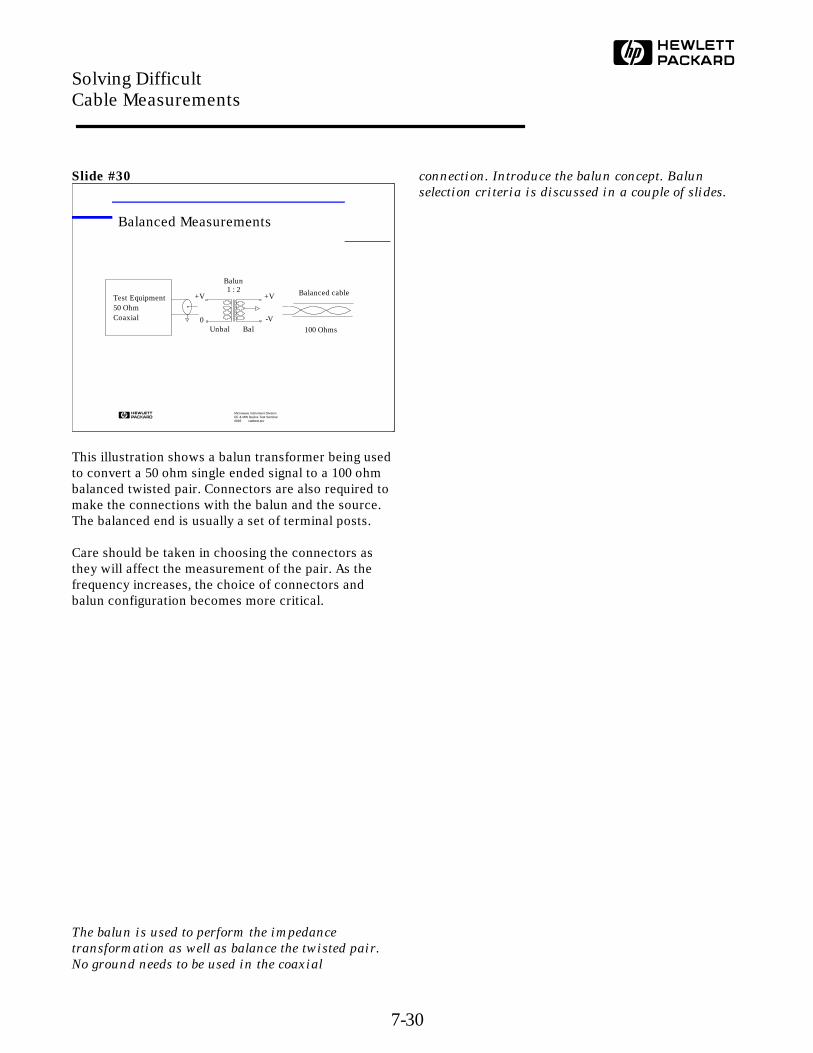
This illustration shows a balun transformer being usedto convert a 50 ohm single ended signal to a 100 ohmbalanced twisted pair. Connectors are also required tomake the connections with the balun and the source.The balanced end is usually a set of terminal posts.
Care should be taken in choosing the connectors asthey will affect the measurement of the pair. As thefrequency increases, the choice of connectors andbalun configuration becomes more critical.
The balun is used to perform the impedance
transformation as well as balance the twisted pair.
No ground needs to be used in the coaxial
connection. Introduce the balun concept. Balun
selection criteria is discussed in a couple of slides.
Microwave Instrument DivisionRF & MW Device Test Seminar0893 cabltest.pre
Balanced Measurements
Unbal Bal
Balun1 : 2
+V +V
-V0
Test Equipment50 OhmCoaxial
Balanced cable
100 Ohms
Solving Difficult Cable Measurements
7-30
Slide #31
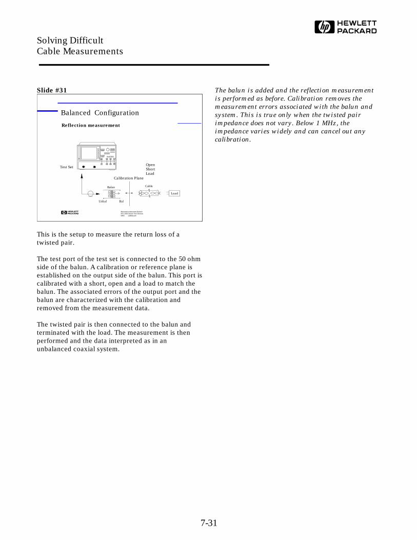
This is the setup to measure the return loss of atwisted pair.
The test port of the test set is connected to the 50 ohmside of the balun. A calibration or reference plane isestablished on the output side of the balun. This port iscalibrated with a short, open and a load to match thebalun. The associated errors of the output port and thebalun are characterized with the calibration andremoved from the measurement data.
The twisted pair is then connected to the balun andterminated with the load. The measurement is thenperformed and the data interpreted as in anunbalanced coaxial system.
The balun is added and the reflection measurement
is performed as before. Calibration removes the
measurement errors associated with the balun and
system. This is true only when the twisted pair
impedance does not vary. Below 1 MHz, the
impedance varies widely and can cancel out any
calibration.
Microwave Instrument DivisionRF & MW Device Test Seminar0893 cabltest.pre
Balanced Configuration
Test Set
Calibration Plane
Unbal Bal
Balun
Load
Reflection measurement
Cable
OpenShortLoad
Solving Difficult Cable Measurements
7-31

Slide #32
Calibration standards must be chosen carefully as the accuracy of thecalibration and measurement depend upon them. A good electricalconnection with the test connectors is most important for all threestandards. The short and open may be just that, open terminals and apiece of wire or copper sheet. The load should be measured carefullyto provide the exact resistance , i.e. a 1% resistor reflects a 1%accuracy in the measurement.
Lead length does not become a factor until the lengths approach asignificant portion of the wavelengths of the frequencies beingmeasured. With 500 MHz as the upper limit of the testing, carefullyshortened leads are the only consideration. This would not be thecase at 5 GHz! Use a connector that is reasonable for the cable beingtested and build a set of standards using the same connector. Avoidusing alligator clips and long test leads!
Balun calibration standards do not exist and must
be created for the measurement setup and fixturing.
Build connectors and standards with the care
required to reflect your measurement needs. It's not
difficult to generate an acceptable set of standards.
Microwave Instrument DivisionRF & MW Device Test Seminar0893 cabltest.pre
Calibration Standards
ConsiderationsAccuracyRepeatablity
GeometryMinimum lead lengthGood electrical connection
OpenShortLoad
Calibration Plane
Unbal Bal
Balun
Solving Difficult Cable Measurements
7-32
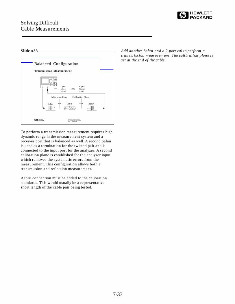
Slide #33
To perform a transmission measurement requires highdynamic range in the measurement system and areceiver port that is balanced as well. A second balunis used as a termination for the twisted pair and isconnected to the input port for the analyzer. A secondcalibration plane is established for the analyzer inputwhich removes the systematic errors from themeasurement. This configuration allows both atransmission and reflection measurement.
A thru connection must be added to the calibrationstandards. This would usually be a representativeshort length of the cable pair being tested.
Add another balun and a 2-port cal to perform a
transmission measurement. The calibration plane is
set at the end of the cable.
Microwave Instrument DivisionRF & MW Device Test Seminar0893 cabltest.pre
Balanced Configuration
BalunBalun
Transmission Measurement
Calibration PlaneCalibration Plane
Cable
OpenShortLoad
OpenShortLoad
Thru
Solving Difficult Cable Measurements
7-33
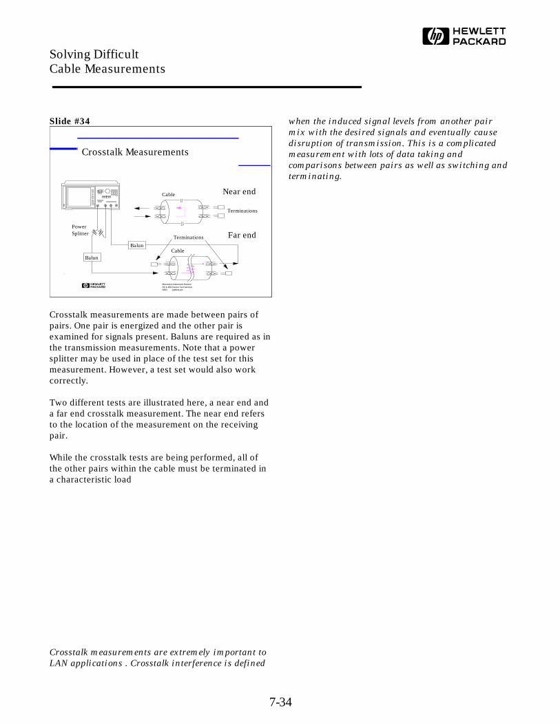
Slide #34
Crosstalk measurements are made between pairs ofpairs. One pair is energized and the other pair isexamined for signals present. Baluns are required as inthe transmission measurements. Note that a powersplitter may be used in place of the test set for thismeasurement. However, a test set would also workcorrectly.
Two different tests are illustrated here, a near end anda far end crosstalk measurement. The near end refersto the location of the measurement on the receivingpair.
While the crosstalk tests are being performed, all ofthe other pairs within the cable must be terminated ina characteristic load
Crosstalk measurements are extremely important to
LAN applications . Crosstalk interference is defined
when the induced signal levels from another pair
mix with the desired signals and eventually cause
disruption of transmission. This is a complicated
measurement with lots of data taking and
comparisons between pairs as well as switching and
terminating.
Microwave Instrument DivisionRF & MW Device Test Seminar0893 cabltest.pre
Crosstalk Measurements
Cable
Terminations
Near end
Terminations
Cable
PowerSplitter
Balun
Balun
Far end
Solving Difficult Cable Measurements
7-34
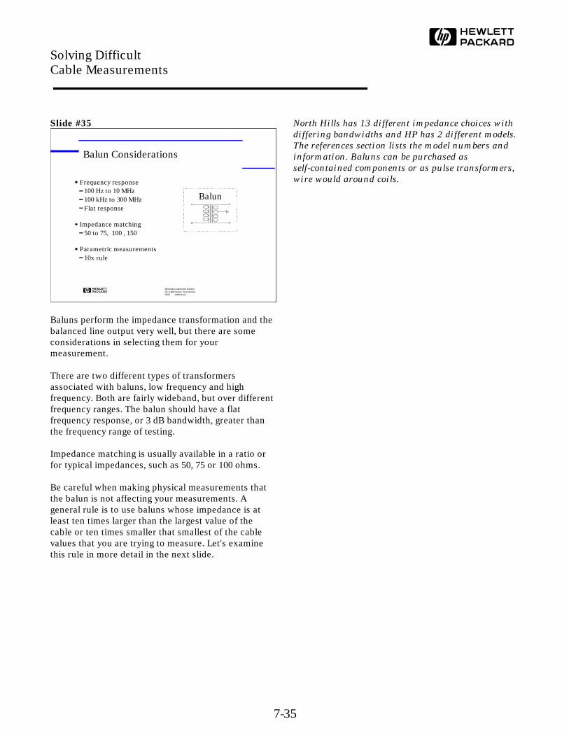
Slide #35
Baluns perform the impedance transformation and thebalanced line output very well, but there are someconsiderations in selecting them for yourmeasurement.
There are two different types of transformersassociated with baluns, low frequency and highfrequency. Both are fairly wideband, but over differentfrequency ranges. The balun should have a flatfrequency response, or 3 dB bandwidth, greater thanthe frequency range of testing.
Impedance matching is usually available in a ratio orfor typical impedances, such as 50, 75 or 100 ohms.
Be careful when making physical measurements thatthe balun is not affecting your measurements. Ageneral rule is to use baluns whose impedance is atleast ten times larger than the largest value of thecable or ten times smaller that smallest of the cablevalues that you are trying to measure. Let's examinethis rule in more detail in the next slide.
North Hills has 13 different impedance choices with
differing bandwidths and HP has 2 different models.
The references section lists the model numbers and
information. Baluns can be purchased as
self-contained components or as pulse transformers,
wire would around coils.
Microwave Instrument DivisionRF & MW Device Test Seminar0893 cabltest.pre
Frequency response100 Hz to 10 MHz100 kHz to 300 MHzFlat response
Impedance matching50 to 75, 100 , 150
Parametric measurements10x rule
Balun Considerations
Balun
Solving Difficult Cable Measurements
7-35
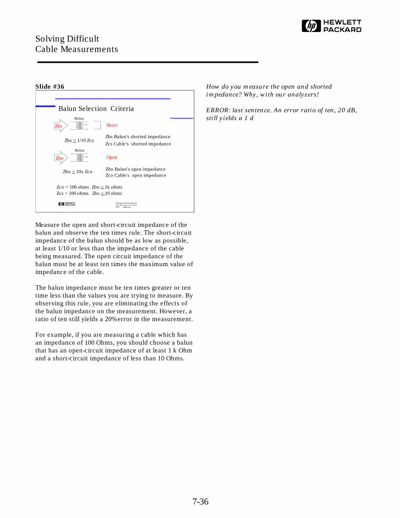
Slide #36
Measure the open and short-circuit impedance of thebalun and observe the ten times rule. The short-circuitimpedance of the balun should be as low as possible,at least 1/10 or less than the impedance of the cablebeing measured. The open circuit impedance of thebalun must be at least ten times the maximum value ofimpedance of the cable.
The balun impedance must be ten times greater or tentime less than the values you are trying to measure. Byobserving this rule, you are eliminating the effects ofthe balun impedance on the measurement. However, aratio of ten still yields a 20% error in the measurement.
For example, if you are measuring a cable which hasan impedance of 100 Ohms, you should choose a balunthat has an open-circuit impedance of at least 1 k Ohmand a short-circuit impedance of less than 10 Ohms.
How do you measure the open and shorted
impedance? Why, with our analyzers!
ERROR: last sentence. An error ratio of ten, 20 dB,
still yields a 1 d
Microwave Instrument DivisionRF & MW Device Test Seminar0893 cabltest.pre
Balun Selection Criteria
Zco = 100 ohms Zbo > 1k ohmsZcs = 100 ohms Zbs < 10 ohms
Balun
Zbo Open
Balun
Zbs Short
Zbs < 1/10 ZcsZbs Balun's shorted impedance
Zcs Cable's shorted impedance
Zbo Balun's open impedanceZco Cable's open impedance
Zbo > 10x Zco
Solving Difficult Cable Measurements
7-36

Slide #37
Standards have been defined for the manufacture oftwisted pair cable and measurement of the associatedparameters. Here are a number of the currentstandards that must be observed and their relationshipto each other. A number of measurements are requiredto meet these standards.
Note that the NEMA specifications specify the entirerange of product specifications, test specifications andthe test methods. Both STP, (Shielded Twisted Pair),and UTP, (Unshielded Twisted Pair) are included inthe specifications.
This table illustrates that there are standards in
existence which are continually evolving and in
transition. There isn't time to explain them. The
latest proposal, June 93 , for TIA/EIA has some
interesting new measurements, such as power sum.
Each of the lines in the crosstalk measurement must
be measured against all the others and then the
results combined mathematically for a worst case
condition. The new trends only lead more toward
automation and fixturing for the measurements.
STP Shielded Twisted Pair
UTP Un-shielded Twisted Pair
Microwave Instrument DivisionRF & MW Device Test Seminar0893 cabltest.pre
Standards
TIA: Telecommunications Industry AssociationEIA: Electronic Industries AssociationNEMA: National Electrical Mfg's. AssociationASTM: American Society for Testing and Materials
Standards Organizations
Standards SpecificationsUTP/STP
Product Spec'sUTP/STP
Test Spec'sUTP/STP
Test MethodsTIA/EIA - 568
ASTM 4566 - 90
NEMA WC - 63
ETL, ULIndependent Product Testing
Solving Difficult Cable Measurements
7-37
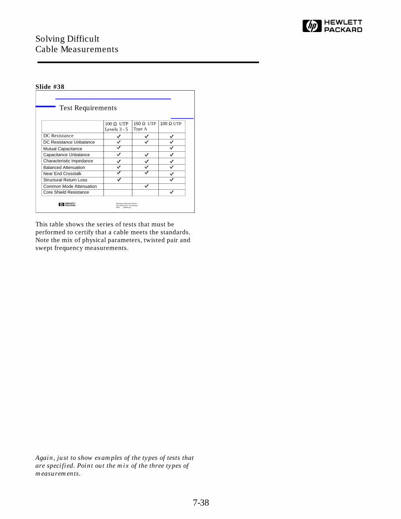
Slide #38
This table shows the series of tests that must beperformed to certify that a cable meets the standards.Note the mix of physical parameters, twisted pair andswept frequency measurements.
Again, just to show examples of the types of tests that
are specified. Point out the mix of the three types of
measurements.
Microwave Instrument DivisionRF & MW Device Test Seminar0893 cabltest.pre
Test Requirements
100 Ω UTPLevels 3 - 5
150 Ω UTPType A
100 Ω UTP
DC ResistanceDC Resistance Unbalance
Mutual CapacitanceCapacitance UnbalanceCharacteristic Impedance
Balanced AttenuationNear End CrosstalkStructural Return LossCommon Mode AttenuationCore Shield Resistance
Solving Difficult Cable Measurements
7-38
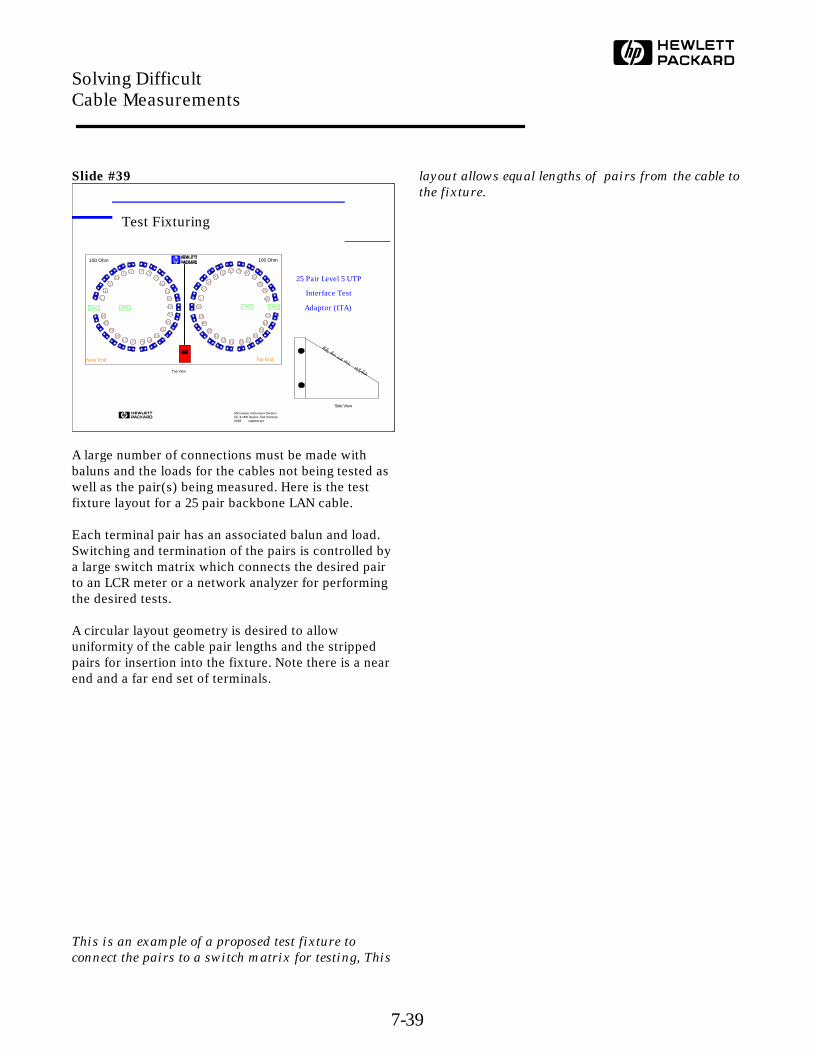
Slide #39
A large number of connections must be made withbaluns and the loads for the cables not being tested aswell as the pair(s) being measured. Here is the testfixture layout for a 25 pair backbone LAN cable.
Each terminal pair has an associated balun and load.Switching and termination of the pairs is controlled bya large switch matrix which connects the desired pairto an LCR meter or a network analyzer for performingthe desired tests.
A circular layout geometry is desired to allowuniformity of the cable pair lengths and the strippedpairs for insertion into the fixture. Note there is a nearend and a far end set of terminals.
This is an example of a proposed test fixture to
connect the pairs to a switch matrix for testing, This
layout allows equal lengths of pairs from the cable to
the fixture.
Microwave Instrument DivisionRF & MW Device Test Seminar0893 cabltest.pre
Test Fixturing
Side View
25 Pair Level 5 UTP
Interface Test
Adaptor (ITA)
Near End Far End
Top View
100 Ohm
1
100 Ohm
2
1
2
3
4
56 7
8
9
10
11
12
13
14
15
16
17
181920211
22
23
24
25
3
4
56 7
8
9
10
11
12
13
14
15
16
17181920
21
22
23
24
25
Solving Difficult Cable Measurements
7-39

Slide #40
The test rack is shown here to illustrate the testequipment required and the cable connection andfixturing. A PC is used to control the operation andprovide a data base of test results. Test that mightrequire weeks manually can be accomplished in amatter of hours.
An HP 8751 network analyzer and an HP 4263 RLCmeter are the test instruments in the system.
This is a proposed system that the Application
Center in Burlington, MA is planning to build. Four
manufacturers have anted up $150K and only one
more is needed. Have the salesman contact Pete
Johnson if there is any interest from a customer in
purchasing or specifying a system.
Peter Johnson
Project Manager
System Engineering Business Unit
Hewlett-Packard Co.
29 Burlington Mall Road
Burlington, MA 01803
Direct (617) 221-4674
FAX (617) 221-5240
Microwave Instrument DivisionRF & MW Device Test Seminar0893 cabltest.pre
Cable Tester Physical Layout
STP 6 PairITA
120 Ohm ITAITA
UTP 25 PairITA
HP 8751A
HP 87512A
HP 4263A
Solving Difficult Cable Measurements
7-40
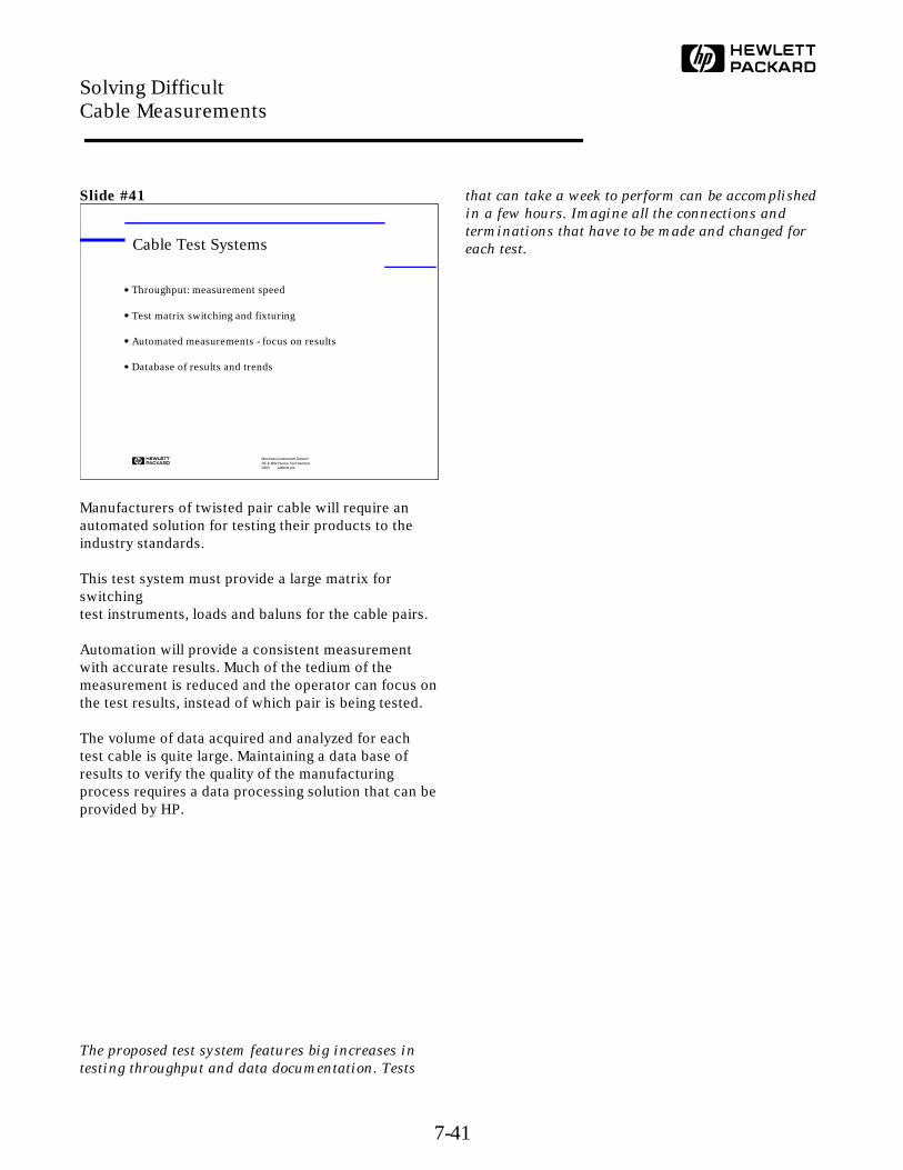
Slide #41
Manufacturers of twisted pair cable will require anautomated solution for testing their products to theindustry standards.
This test system must provide a large matrix forswitchingtest instruments, loads and baluns for the cable pairs.
Automation will provide a consistent measurementwith accurate results. Much of the tedium of themeasurement is reduced and the operator can focus onthe test results, instead of which pair is being tested.
The volume of data acquired and analyzed for eachtest cable is quite large. Maintaining a data base ofresults to verify the quality of the manufacturingprocess requires a data processing solution that can beprovided by HP.
The proposed test system features big increases in
testing throughput and data documentation. Tests
that can take a week to perform can be accomplished
in a few hours. Imagine all the connections and
terminations that have to be made and changed for
each test.
Microwave Instrument DivisionRF & MW Device Test Seminar0893 cabltest.pre
Cable Test Systems
Throughput: measurement speed
Test matrix switching and fixturing
Automated measurements - focus on results
Database of results and trends
Solving Difficult Cable Measurements
7-41
Slide #42
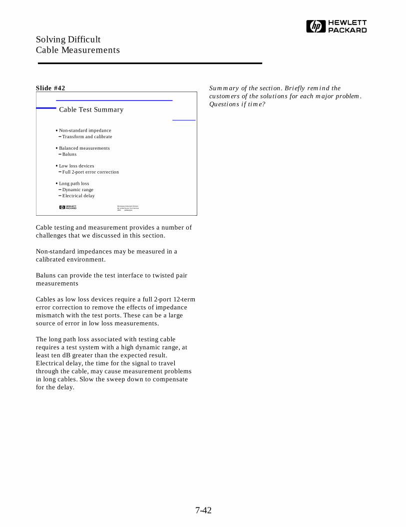
Cable testing and measurement provides a number ofchallenges that we discussed in this section.
Non-standard impedances may be measured in acalibrated environment.
Baluns can provide the test interface to twisted pairmeasurements
Cables as low loss devices require a full 2-port 12-termerror correction to remove the effects of impedancemismatch with the test ports. These can be a largesource of error in low loss measurements.
The long path loss associated with testing cablerequires a test system with a high dynamic range, atleast ten dB greater than the expected result.Electrical delay, the time for the signal to travelthrough the cable, may cause measurement problemsin long cables. Slow the sweep down to compensatefor the delay.
Summary of the section. Briefly remind the
customers of the solutions for each major problem.
Questions if time?
Microwave Instrument DivisionRF & MW Device Test Seminar0893 cabltest.pre
Cable Test Summary
Non-standard impedanceTransform and calibrate
Balanced measurementsBaluns
Low loss devicesFull 2-port error correction
Long path lossDynamic rangeElectrical delay
Solving Difficult Cable Measurements
7-42
References
Hewlett-Packard Company, Vector Seminar, VectorMeasurements of High Frequency Networks (HP publication number 5958-0387).
Hewlett-Packard Company, Scalar Seminar, ScalarNetwork Measurements (HP publication number5954-1586).
Society of Cable Television Engineers Engineeringcommittee, Interface procedures subcommitteerecommended practices and test methods for theCATV Industry, IPS-TP-007 Preliminary test methodfor Structural Return Loss.
Application Notes
Measuring the Impedance of Balanced Cables, Application Note 339-4 (HP publication number5950-2918).
Measuring Cable Parameters, Application Note 380-2(HP Literature number 5950-2399).
Balanced Cable Measurement with an ImpedanceAnalyzer / LCR Meter / Network Analyzer, ApplicationNote 346-2 (HP Literature number 5091-4480).
Video Tapes
Balanced Cable Measurement,
(HP Part number 90468T).
Baluns
Hewlett-Packard Company
Model No. Impedance Freq. Range Connectors16316A 50 : 100 100 Hz - 10 MHz BNC - BPs
16317A 50 : 600 100 Hz - 10 MHz BNC - BPs
North Hills Electronics
Model No. Impedance Freq. Range Connectors0101BB 50 : 75 0.1 - 125 MHz BNC - lugs
0300BB 50 : 100 0.1 - 100 MHz BNC - lugs
0400BB 50 :150 0.1 - 100 MHz BNC - lugs
And a wide assortment of other configurations
North Hills Electronics A Porta Systems Company575 Underhill Boulevard, Syossett, NY, USATel. 516-682-7740 FAX 516-682-7704
Solving Difficult Cable Measurements
7-43