Solvent Ink Color Inkjet Printer IP-6900 · IP-6900 Seiko I Infotech Inc. ... (for head up/down...
266
User's Guide Solvent Ink Color Inkjet Printer IP-6900 Seiko I Infotech Inc. Read this User's Guide to use the printer safely and properly. Keep this manual in a place where you can quickly access it at any time. U00094405401
Transcript of Solvent Ink Color Inkjet Printer IP-6900 · IP-6900 Seiko I Infotech Inc. ... (for head up/down...
User's Guide
Solvent InkColor Inkjet Printer
IP-6900
Seiko I Infotech Inc.
Read this User's Guide to use the printer safely and
properly. Keep this manual in a place where you
can quickly access it at any time.
U00094405401

IP-6900 Solvent Ink Color Inkjet Printer User's GuideDocuments Number U00094405401
First Edition, May 2005Second Edition, June 2005
Copyright © 2005 by Seiko I Infotech Inc.All rights reserved
Seiko I Infotech Inc. reserves the right to make changes without notice to the specifications andmaterials contained herein and shall not be responsible for any damages (including consequen-tial) caused by reliance on the materials presented, including but not limited to typographical,arithmetic, or listing errors.
Please address any questions, comments, or suggestions to:
Seiko I Infotech Inc.8, Nakase 1-chome, Mihama-ku, Chiba-shi.Chiba 261-8507, Japan
This manual acknowledges the following trademarks:
SII is a trademark of Seiko Instruments Inc.All other trademarks are the property of their respective companies.
This equipment has been tested and found to comply with the limits for a Class A digital device,
pursuant to Part 15 of the FCC Rules. These limits are designed to provide reasonable protection
against harmful interference when the equipment is operated in a commercial environment.
This equipment generates, uses, and can radiate radio frequency energy and, if not installed and
used in accordance with the instruction manual, may cause harmful interference to radio
communications. Operation of this equipment in a residential area is likely to cause harmful
interference, in which case the user will be required to correct the interference at his own expense.
Durch die Kennzeichnung dieses Produktes mit dem CE-Zeichen erklärt Seiko den folgenden
Direktiven der Europäischen Union zu entsprechen (mit Wirkung vom siehe Datum):
Januar 1996:- EG-Direktive 73/23/EEC ergänzt durch EG-Direktive 93/68/EEC, Angleichung der
Gesetze der einzelnen Mitgliedsstaaten bezüglich Geräten mit niedriger Betriebsspannung.
Januar 1996:- EG-Direktive 89/336/EEC, Angleichung der Gesetze der einzelnen Mitgliedsstaaten
bezüglich elektromagnetischer Kompatibilität.
Den vollständigen Text dieser Erklärung einschließlich der Definition der entsprechenden
Direktiven sowie der jeweiligen Standards erhalten Sie von Ihrem Seiko Colorgrafx Systems
Kundendienst oder Ihrem Seiko Engineering Systems Kundendienst.

Thank you very much for purchasing the IP-6900 Color Inkjet
Printer (simply called the printer below).
This printer is a color inkjet printer that uses solvent ink, supports
104 inch media width, and has a built-in SCSI interface.
This manual, the IP-6900 User's Guide, describes the features of
the printer, names of components, information needed before use,
and basic operations, such as how to turn the power ON and OFF
and set media and ink.
The following items should be read before reading Section 1:
- Contents of package
- Safety precautions
- Handling precautions
- Notation
Read these items to use the printer safely and properly. Keep this
manual in a place where you can quickly access it at any time.
Introduction


i
Contents of PackageThe printer components, including options, are installed on the main
unit on delivery. Make sure that the items listed on this page and
the next page are present.
If any parts are missing or damaged, contact the shop where you
purchased the product or the nearest service center.
Printer main unit <1>
• Built-in SCSI interface.
• Main unit includes the paper feeder and take-up unit
Basic components
ii
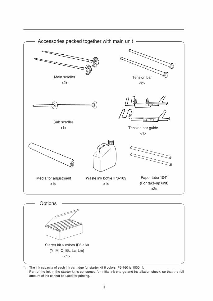
*: The ink capacity of each ink cartridge for starter kit 6 colors IP6-160 is 1000ml.Part of the ink in the starter kit is consumed for initial ink charge and installation check, so that the fullamount of ink cannot be used for printing.
Media for adjustment
<1>
Starter kit 6 colors IP6-160
(Y, M, C, Bk, Lc, Lm)
<1>
Waste ink bottle IP6-109
<1>
Paper tube 104"
(For take-up unit)
<2>
Main scroller
<2>
Sub scroller
<1>
Tension bar
<2>
Tension bar guide
<1>
Accessories packed together with main unit
Options
iii
• Dryer 100 (IP-270) : 1
• Exhaust Attachment 100 : 1
• PS RIP (PhotoPrint 4 DX) : 1
• PS RIP (PhotoPrint 4 Server) : 1
• Footswitch : 1
• SCSI cable (9 m) : 1
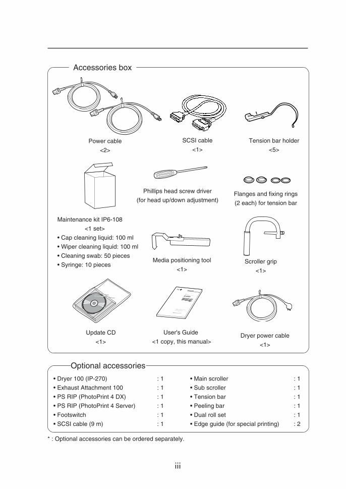
Maintenance kit IP6-108
<1 set>
• Cap cleaning liquid: 100 ml
• Wiper cleaning liquid: 100 ml
• Cleaning swab: 50 pieces
• Syringe: 10 pieces
Phillips head screw driver
(for head up/down adjustment)
Media positioning tool
<1>
Update CD
<1>Dryer power cable
<1>
Tension bar holder
<5>
Scroller grip
<1>
Power cable
<2>
SCSI cable
<1>
User's Guide
<1 copy, this manual>
• Main scroller : 1
• Sub scroller : 1
• Tension bar : 1
• Peeling bar : 1
• Dual roll set : 1
• Edge guide (for special printing) : 2
Optional accessories
Accessories box
* : Optional accessories can be ordered separately.
Flanges and fixing rings
(2 each) for tension bar
iv
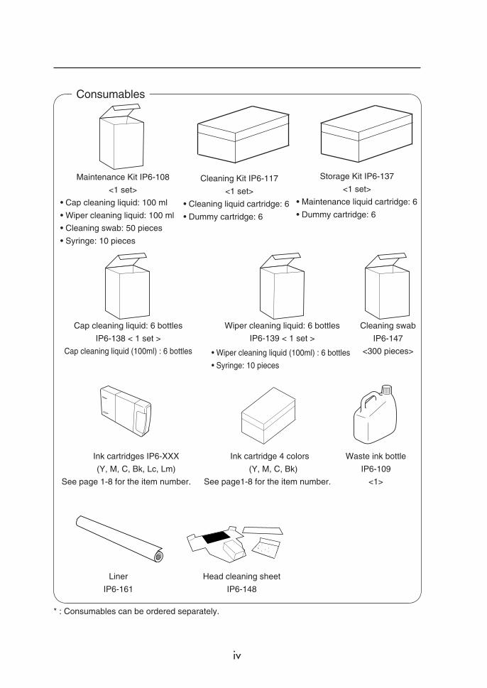
Consumables
* : Consumables can be ordered separately.
Maintenance Kit IP6-108
<1 set>
• Cap cleaning liquid: 100 ml
• Wiper cleaning liquid: 100 ml
• Cleaning swab: 50 pieces
• Syringe: 10 pieces
Storage Kit IP6-137
<1 set>
• Maintenance liquid cartridge: 6
• Dummy cartridge: 6
Cleaning Kit IP6-117
<1 set>
• Cleaning liquid cartridge: 6
• Dummy cartridge: 6
Cap cleaning liquid: 6 bottles
IP6-138 < 1 set >
Cap cleaning liquid (100ml) : 6 bottles
Wiper cleaning liquid: 6 bottles
IP6-139 < 1 set >
Cleaning swab
IP6-147
<300 pieces>
Waste ink bottle
IP6-109
<1>
Ink cartridges IP6-XXX
(Y, M, C, Bk, Lc, Lm)
See page 1-8 for the item number.
• Wiper cleaning liquid (100ml) : 6 bottles
• Syringe: 10 pieces
Ink cartridge 4 colors
(Y, M, C, Bk)
See page1-8 for the item number.
Liner
IP6-161
Head cleaning sheet
IP6-148
v
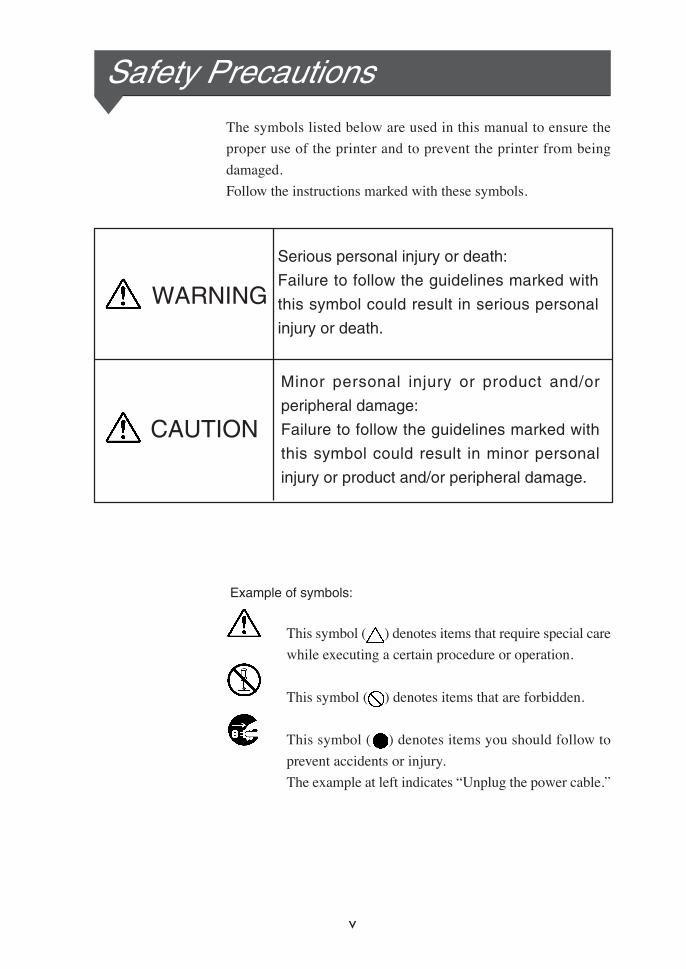
Example of symbols:
This symbol ( ) denotes items that require special care
while executing a certain procedure or operation.
This symbol ( ) denotes items that are forbidden.
This symbol ( ) denotes items you should follow to
prevent accidents or injury.
The example at left indicates “Unplug the power cable.”
Safety PrecautionsThe symbols listed below are used in this manual to ensure the
proper use of the printer and to prevent the printer from being
damaged.
Follow the instructions marked with these symbols.
Minor personal injury or product and/or
peripheral damage:
Failure to follow the guidelines marked with
this symbol could result in minor personal
injury or product and/or peripheral damage.
Serious personal injury or death:
Failure to follow the guidelines marked with
this symbol could result in serious personal
injury or death.
WARNING
CAUTION

vi
Use the power supply voltage specified on the nameplate. DO NOT
plug several devices into one electrical outlet as this might result in fire
or electric shock.
Make sure the printer is well grounded. If it is not, a short circuit may
cause fire or electrical shock.
DO NOT disassemble or remodel the printer. DO NOT repair the printer
by yourself. Doing so may cause fire, electric shock or other accidents.
DO NOT damage, break, process, or heat the power cable. If it is
damaged, replace it with a new one. Using a damaged power cable may
cause fire or electric shock.
NEVER use the printer in a place of extreme humidity or any place
where it can possibly be splashed by any liquids. Liquids which get into
the printer could cause fire, electric shock, or other serious accidents.
DO NOT remove the covers attached to the printer because they contain
high voltage and extremely hot parts. Careless removal might result in
an electric shock or burn.
DO NOT allow metal or liquids to touch the internal parts of the printer.
Doing so may cause fire, electric shock, or other accidents.
DO NOT disconnect or connect the power cable with wet hands. Doing
so may lead to electric shock.
Turn the printer OFF and unplug the power cable immediately if it sparks.
WARNING
vii
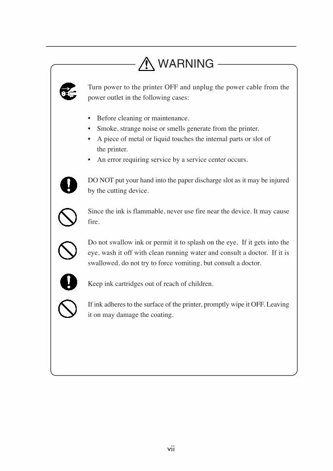
Turn power to the printer OFF and unplug the power cable from the
power outlet in the following cases:
• Before cleaning or maintenance.
• Smoke, strange noise or smells generate from the printer.
• A piece of metal or liquid touches the internal parts or slot of
the printer.
• An error requiring service by a service center occurs.
DO NOT put your hand into the paper discharge slot as it may be injured
by the cutting device.
Since the ink is flammable, never use fire near the device. It may cause
fire.
Do not swallow ink or permit it to splash on the eye. If it gets into the
eye, wash it off with clean running water and consult a doctor. If it is
swallowed, do not try to force vomiting, but consult a doctor.
Keep ink cartridges out of reach of children.
If ink adheres to the surface of the printer, promptly wipe it OFF. Leaving
it on may damage the coating.
WARNING

viii
Handle the media rolls with care because they are very heavy. Dropping
them could lead to personal injury.
Hold the electric cable by the plug when connecting or disconnecting it.
Holding the cable directly may cause the cable to fray or break, which
could lead to electric shock and/or fire.
DO NOT get ink on your skin or clothes. Wash off any ink immediately
with soapy water.
DO NOT put any paper rolls on an unstable table or a tilted surface as
they could fall, causing injury.
The heater will be hot.
Be careful not to touch it and not to be burned.
In order to ensure the safe operation of the printer heed all of the cautions
and warnings contained throughout this manual.
CAUTION

ix
Handling Precautions
Power Supply
1. Install the printer near an easily accessible electrical outlet.2. Do not provide power to the printer through the same power
line as for noise-generating devices, such as a motor.3. Use a power supply matched with the printer specification.4. Connect the power cable directly to an electrical outlet. Do not
plug several devices into one electrical outlet.
Printer
1. Do not place anything on top of the printer. Do not rest yourelbows on the printer.
2. Open and close the top cover gently from the front of the printerwith both hands.
3. Before connecting or disconnecting the interface connector, turnthe printer OFF.
4. Do not clean the surface of the cover with benzene or paintthinner. The coating may come off or deteriorate.Wipe the cover clean with a soft cloth. If the cover is very dirty,use a cloth moistened with a neutral detergent.
5. Do not touch the ink-jet head surface.
Regular Inspection and Maintenance
The following regular inspection and maintenance must beperformed in terms of characteristics of solvent ink:1. Clean the capping unit and wiper blade every day.2. Check moisture of wiper sponge every day.3. Perform head cleaning every month.4. Perform service cleaning when leaving the printer for a long
time (2 weeks or more with power OFF.)5. Perform head washing and ink charging before printing after
leaving the printer idle for a long time.
See pages 2-68 and 2-82 for regular inspection and maintenance.

x
Consumables
1. Always use the recommended consumables (media, ink, etc.).
Failure to follow this instruction may cause poor print quality
or breakdown.
2. Do not use ink past the expiration date as this may cause a
breakdown.
3. Put a used ink cartridge into a plastic bag and dispose of it as
industrial waste. Observe local regulations for disposal of waste
ink bottles.
4. Do not get ink on your skin or clothes. Wash any ink off
immediately with soapy water.
5. Check the waste ink bottle regularly so as not to permit waste
ink to leak.
6. When the waste ink bottle is installed or removed, spread a stain
preventing sheet so as not to stain the floor with spilt ink.
7. Store ink in a dark and cool place.
NEVER store ink in high temperature or direct sunshine.
Doing so may cause ink to deteriorate.
8. Do not attempt to disassemble ink cartridges.
9. Commercially available media for use with solvent ink can be
used in this printer.
xi
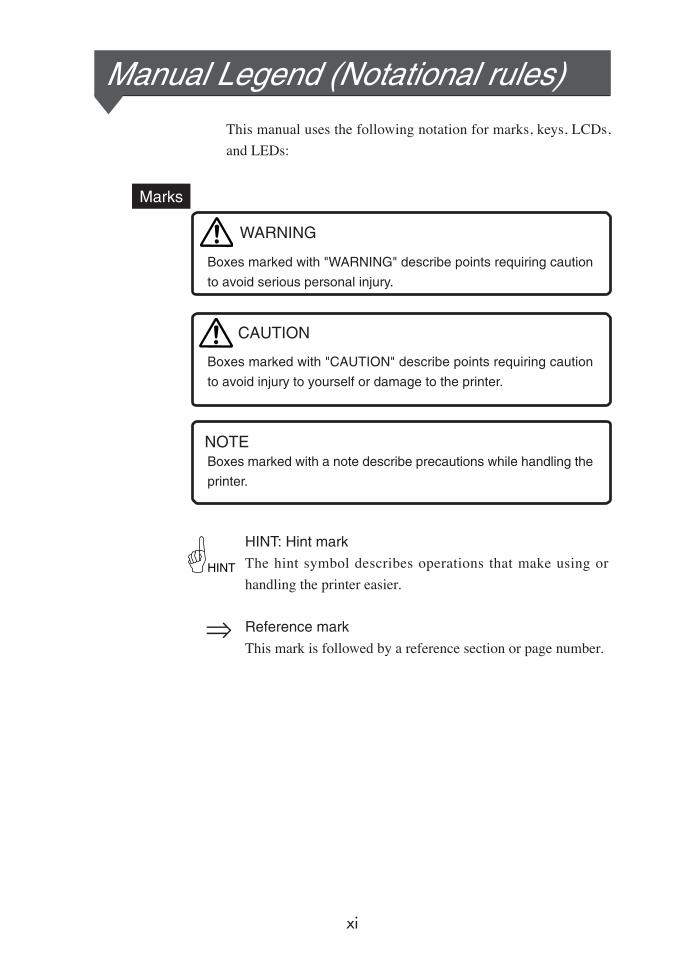
Marks
Boxes marked with "WARNING" describe points requiring caution
to avoid serious personal injury.
Boxes marked with "CAUTION" describe points requiring caution
to avoid injury to yourself or damage to the printer.
Boxes marked with a note describe precautions while handling the
printer.
HINT: Hint mark
The hint symbol describes operations that make using or
handling the printer easier.
Reference mark
This mark is followed by a reference section or page number.
Manual Legend (Notational rules)This manual uses the following notation for marks, keys, LCDs,
and LEDs:
NOTE
HINT
WARNING
CAUTION

xii
1 Press to put the
printer offline.
2 Press to select
the first menu in the
local operation mode.
3 Press again to
select the second menu
in the local operation
mode.
4 Press to enter the
function menu.
This represents a key
on the operation panel.This represents the LCD on the
operation panel.
On
Flashing
Off
Example 2: LED states
The LED states "On", "flashing", and "Off" are indicated as follows:
Example 1: Keys in the text and display on the LCD
INK ENTRY
PAPER F. ADJ
SERVICE FEED
CLEANING
FUNC SYSTEM
ADJUST RESET
This represents a key to select the
menu. (Ex. : key)
Notation for Keys/LCD/LED
xiii
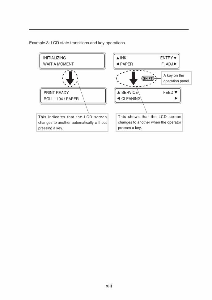
PRINT READY
ROLL : 104 / PAPER
INK ENTRY
PAPER F. ADJ
Example 3: LCD state transitions and key operations
A key on the
operation panel.
This indicates that the LCD screen
changes to another automatically without
pressing a key.
This shows that the LCD screen
changes to another when the operator
presses a key.
INITIALIZING
WAIT A MOMENT
SERVICE FEED
CLEANING
CONTENTS-1
TABLE OF CONTENTS
Introduction
Contents of Package ........................................................................... i
Safety Precautions.............................................................................. v
Handling Precautions.......................................................................... ix
Manual Legend (Notational rules) ....................................................... xi
Section 1 Getting Started 1-1
Operating Conditions ....................................................................... 1-2
Installation Space ................................................................ 1-2
Environmental Conditions ................................................... 1-3
Consumables ................................................................................... 1-5
Media ................................................................................... 1-5
Ink Cartridge ........................................................................ 1-8
Waste Ink Bottle ................................................................ 1-11
Maintenance Kit ................................................................. 1-12
Cap Cleaning Liquid (6-Bottle Set) .................................... 1-12
Wiper Cleaning Liquid (6-Bottle Set) ................................. 1-13
Cleaning Swab .................................................................. 1-13
Storage Kit ......................................................................... 1-13
Cleaning Kit ....................................................................... 1-13
Liner .................................................................................. 1-14
Head Cleaning Sheet ........................................................ 1-14
External Views, Part Names, and Functions ................................. 1-15
Front View (Feeder unit) .................................................... 1-15
Rear View (Winder unit) .................................................... 1-16
Heater ................................................................................ 1-17
Operation Panel ................................................................ 1-18
Heater Control Panel ......................................................... 1-20
Dryer 100 (Option) ............................................................ 1-21
Footswitch (Option) .......................................................... 1-21
SCSI Cable (9 m) (Option) ............................................... 1-21

CONTENTS-2
Main Scroller (Option) ...................................................... 1-21
Sub Scroller (Option) ........................................................ 1-21
Exhaust Attachment 100 (Option) .................................... 1-21
Tension Bar Set (Option) .................................................. 1-22
Peeling Bar Set (Option) .................................................. 1-22
Dual Roll Kit (Option) ........................................................ 1-22
Edge Guide (Option) ........................................................ 1-22
PS RIP (PhotoPrint 4 DX) (Option) ................................... 1-22
PS RIP (PhotoPrint 4 Server) (Option) ............................. 1-22
Section 2 Basic Operations 2-1
Connecting to a Computer ............................................................... 2-2
System Configuration (Connection Example) ..................... 2-2
Connection Procedure ......................................................... 2-2
Turning the Power ON/OFF ............................................................. 2-5
Turning the Power ON ......................................................... 2-6
Turning the Power OFF 1 .................................................. 2-10
Turning the Power OFF 2 .................................................. 2-10
Installing/Removing the Media....................................................... 2-12
Installing Main Scroller ...................................................... 2-12
Media Setting .................................................................... 2-15
Installing the Sub Scroller .................................................. 2-21
Installing the Sub Scroller on the Printer ........................... 2-22
Installing or Removing the Cut Sheet ................................ 2-25
Installing the Media Roll in the Winder .............................. 2-27
Removing the Media Roll from the Printer ........................ 2-34
Replacing Media on Main Scroller ..................................... 2-35
Replacing Media on Sub Scroller ...................................... 2-35
Replacing Jammed Media Roll .......................................... 2-35
Paper Feed Correction Value Setting ................................ 2-36
CONTENTS-3
Replacing Ink Cartridges ............................................................... 2-41
Ink Cartridge Replacement Procedure .............................. 2-41
Replacing an Empty Ink Cartridge ..................................... 2-43
If an Ink Cartridge is not Installed ...................................... 2-44
Replacing Cartridges during Printing ................................. 2-45
Replacing 4-Color Ink Cartridges ...................................... 2-47
If an Ink Cartridge is not Detected ..................................... 2-48
Replacing the Waste Ink Bottle...................................................... 2-49
Waste Ink Bottle Replacement Procedure ........................ 2-49
If the Waste Ink Bottle is Full ............................................. 2-51
If the Waste Ink Bottle is not Installed ............................... 2-52
Tension Bar Length Adjustment .................................................... 2-53
Head Cleaning "CLEANING" ......................................................... 2-55
Paper Feed "FEED" ....................................................................... 2-57
Using the Origin Point Setting Function ............................ 2-58
Changing Heater Control Setting Temperature ............................. 2-62
Using the Media Pressure Alternation Lever ................................. 2-65
Using the Head Up/Down Lever .................................................... 2-66
Using the Media Edge Guard ........................................................ 2-68
Using the Print Pause/Restart and Cancel Keys ........................... 2-69
Inspection & Maintenance ............................................................. 2-70
Regular inspection and maintenance guide ...................... 2-70
Daily inspection and maintenance ..................................... 2-71
Monthy inspection and maintenance ................................. 2-77
When leaving the printer for a long time (2 weeks or more) in power OFF state ..... 2-77
When restarting the printer after a long absence (2 weeks or more) ....... 2-78
When restarting the printer after a long absence (within 2 weeks) in power OFF state . 2-80
When leaving the printer with power OFF for one month or more ..... 2-81
Cleaning ............................................................................ 2-82
CONTENTS-4
Section 3 Operation Panel Menu Operations 3-1
LCD Messages and Printer State .................................................... 3-2
Display on the LCD ............................................................. 3-2
Operation in Online State ................................................................ 3-4
Basic Menu Operation in Offline State........................................... 3-10
Menu Hierarchical Structure .............................................. 3-10
Menu Tree ......................................................................... 3-11
Basic Operations and Keys ............................................... 3-17
Operation Procedure for Choice Input, Value Input,
Execution, and Character Input ......................................... 3-18
Menu Operations ........................................................................... 3-24
INK Menu .......................................................................... 3-24
PAPER Menu .................................................................... 3-25
ENTRY Menu .................................................................... 3-27
F.ADJ Menu....................................................................... 3-46
SERVICE Menu ................................................................. 3-49
CLEANING Menu .............................................................. 3-53
FEED Menu ....................................................................... 3-54
FUNC Menu....................................................................... 3-55
ADJUST Menu................................................................... 3-57
SYSTEM Menu .................................................................. 3-61
RESET Menu..................................................................... 3-66
Section 4 Special Printing 4-1
Special Printing ................................................................................ 4-2
Print Modes ......................................................................... 4-2
Double-Sided Printing ......................................................... 4-4
Mesh Tarpaulin Printing ...................................................... 4-4
Textile Printing ..................................................................... 4-4
Dual Roll Print ..................................................................... 4-4

CONTENTS-5
Double-Sided Printing ...................................................................... 4-5
Types of Double-Sided Printing ........................................... 4-5
Printing on Back Side from Winding unit ............................. 4-5
Printing on Back Side from Paper Feeder ......................... 4-12
Printing on Back Side
from Paper Feeder After Rewinding .................................. 4-20
Using the Liner .................................................................. 4-25
Printing on Mesh Tarpaulin ............................................................ 4-35
Section 5 Heater Controller Menu Operation 5-1
Temperature Control ........................................................................ 5-2
LCD Display ..................................................................................... 5-4
Parameter Setup Mode.................................................................... 5-6
Error Messages ............................................................................. 5-10
Section 6 Troubleshooting 6-1
Troubleshooting ............................................................................... 6-2
Clearing Jams .................................................................................. 6-3
When an Error Message Appears ................................................... 6-4
Service Call Errors............................................................... 6-4
Communication Errors ......................................................... 6-6
Operator Call Errors ............................................................ 6-7
When the Printer Fails to Work Correctly ...................................... 6-12
When a Print Error Occurs ............................................................. 6-13
When There is an Abnormal Sound............................................... 6-14
When It is Desired to Move the Printer .......................................... 6-15
Appendix A-1
Basic Specifications ......................................................................... A-2
Printer Specifications ........................................................... A-2

1-1
Sect
ion
1 G
ettin
g St
arte
d (B
asic
kno
wle
dge)
Section 1 Getting Started(Basic knowledge)
This section provides necessary information to operate the
printer. Familiarize yourself with the basics of the printer
before reading Section 2 and later.
Operating Conditions
Consumables
External Views, Part Names, and Functions
Contents of this section

1-2
Operating ConditionsThis section describes the operating conditions for the printer.
Installation Space
There must be sufficient space around the printer for the replacement
of frequently used parts, for the output of drawings, and for
ventilation. In addition, maintenance space, shown below, is
required to repair the printer or replace components.
The installation/maintenance space is shown in the following figure:
Installation and maintenance space
Height direction: 1700
(Unit : mm)
400 400
1000
1000
12345678901234567890123456789012123456789012341234567890123456789012345678901212345678901234123456789012345678901234567890121234567890123412345678901234567890123456789012123456789012341234567890123456789012345678901212345678901234123456789012345678901234567890121234567890123412345678901234567890123456789012123456789012341234567890123456789012345678901212345678901234123456789012345678901234567890121234567890123412345678901234567890123456789012123456789012341234567890123456789012345678901212345678901234123456789012345678901234567890121234567890123412345678901234567890123456789012123456789012341234567890123456789012345678901212345678901234123456789012345678901234567890121234567890123412345678901234567890123456789012123456789012341234567890123456789012345678901212345678901234
(Front side)
1-3
Sect
ion
1 G
ettin
g St
arte
d (B
asic
kno
wle
dge)
Operating Conditions
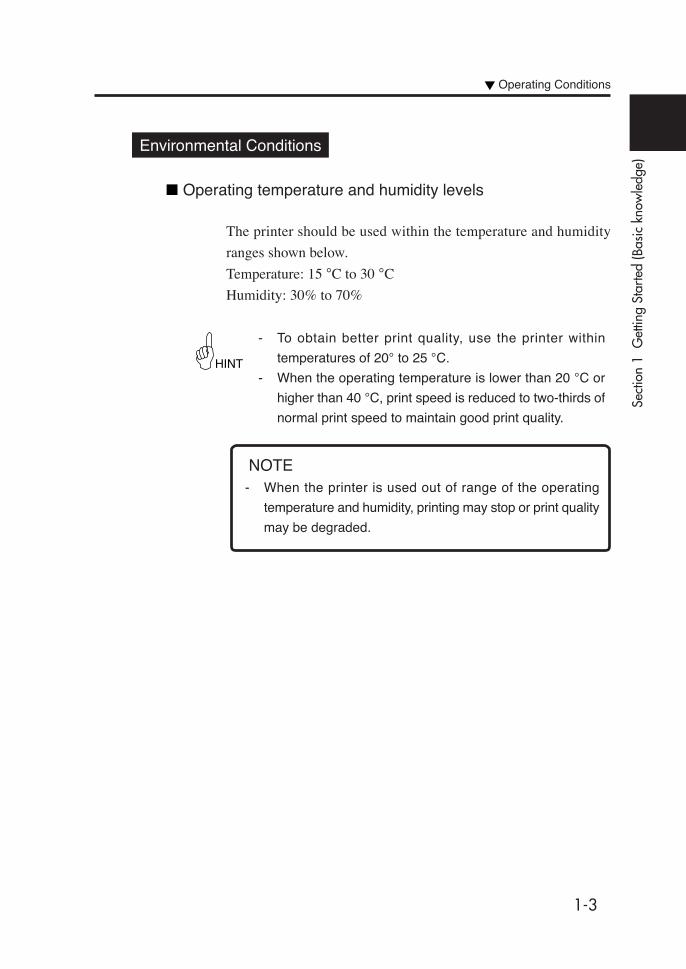
Environmental Conditions
Operating temperature and humidity levels
The printer should be used within the temperature and humidity
ranges shown below.
Temperature: 15 °C to 30 °C
Humidity: 30% to 70%
- To obtain better print quality, use the printer within
temperatures of 20° to 25 °C.
- When the operating temperature is lower than 20 °C or
higher than 40 °C, print speed is reduced to two-thirds of
normal print speed to maintain good print quality.
HINT
NOTE- When the printer is used out of range of the operating
temperature and humidity, printing may stop or print quality
may be degraded.

1-4
Places where the printer must not be installed
Do not install the printer in the following places:
- A location near fire
- Places exposed to direct sunlight
- Places subject to vibration
- Places with excessive dust
- Places subject to extreme changes in temperature or humidity
- Places near an air conditioner or a heater
- Places where the printer may get wet
- Places subject to direct air circulation from vents
- Places near a diazo copier that may generate ammonia gas
- Places with poor ventilation
- Unstable places

1-5
Sect
ion
1 G
ettin
g St
arte
d (B
asic
kno
wle
dge)
Media
Available media typesThe following types of media are available:
For details, ask our sales office or a nearby agent.
• Vinyl chloride
• FF
• Tarpaulin
• Mesh tarpaulin
• Fabric banner (cloth)
Contact our service center for details.
Consumables
Precautions for storing media- Avoid direct sunlight and water both before and after opening
the package. Put media in a box or envelope to prevent dust and
store media in a dry, cool and dark place.
- Avoid rapid change of temperature and humidity, and store
media where condensation will not occur.
- Do not store media standing on end to prevent disorder of media
and damage to the roll edge.
- Do not pile up media rolls.
Precautions for disposing of media- Dispose of media in accordance with local conditions and
regulations.
1-6
Precautions in use- Avoid change of temperature or humidity after opening the
package.
Set media in the printer after leaving media in the operation
environment for 3 hours or more. Suppress change of humidity
by turning the air conditioner ON/OFF.
- Due to media characteristics, curling of media in low humidity
and wrinkling of media in high humidity may occur easily.
Use media in a normal temperature and humidity environment
(around 23 °C and 50%RH).
- Do not use scratched, wrinkled, curled, or dust-stained part of
media.
Especially, damaged edges (both edges) affect media feeding.
Also, do not drop or wet the media. Doing so may adversely
affect print quality and cause malfunctioning.
- Hold margins of the media so as not to touch the print surface.
Adhesion of sebaceous matter or sweat may adversely affect
print quality.
- Roll media correctly before setting in the printer.
Precautions for handling prints.- Do not touch the print surface before ink dries.
Hold margins of the media for handling.
Especially use care within 24 hours after printing.
- Rubbing the print surface causes color fading or color transfer.
Do not superimpose print surfaces, to prevent color transfer.
- Do not superimpose on copy prints or laser prints, to prevent
sticking due to ink or toner.
- Do not rub, scratch, or hold the media, to prevent peeling.
- Do not rub or leave the media in wet condition, to prevent
blurring.
1-7
Sec
tion
1 G
ettin
g S
tart
ed (
Bas
ic k
now
ledg
e)
Consumables
Other precautions- Aging of media causes color fading and a change in quality.
Check media condition and use well-conditioned media.
- Media dust due to cutting may cause floating of laminated
coating.
- When using media with glue, adhesive matter (glue) may stick
to the platen.
In this case, wipe up the adhesive matter, referring to "Section 2
Inspection & Maintenance".
Sticking of adhesive matter may cause paper jamming.

1-8
Ink Cartridge
Ink typesUse our recommended ink cartridges listed below.
[6-color ink cartridge] 1 cartridge/box
NOTES
- Failure to use the recommended ink cartridge may lead to
deterioration of print quality or printer malfunction.
- The ink lifetime is 12 months after the manufacture date.
- Do not shake ink cartridges before use.
- All six color cartridges must be installed.
If any of the cartridges is removed, install a new one.
Item No. Ink color Ink capacity
IP6-101 Y (Yellow) 1000 ml
IP6-102 M (Magenta) 1000 ml
IP6-103 C (Cyan) 1000 ml
IP6-104 Bk (Black) 1000 ml
IP6-105 Lc (Light Cyan) 1000 ml
IP6-106 Lm (Light Magenta) 1000 ml
Item No. Ink color Ink capacity
IP6-141 Y (Yellow) 1000 ml
IP6-142 M (Magenta) 1000 ml
IP6-143 C (Cyan) 1000 ml
IP6-144 Bk (Black) 1000 ml
[4-color ink cartridge] 3 cartridge/box

1-9
Sec
tion
1 G
ettin
g S
tart
ed (
Bas
ic k
now
ledg
e)
Consumables
CAUTION
WARNING
Ink cartridges must be installed in all six slots. The positions of ink
cartridges are specified by color. (See the figure below.)
Black Light Magenta Light Cyan Yellow Magenta Cyan
- Never bring the ink close to fire. Failure to follow this warning
might result in fire.
- Do not swallow ink or let it splash on the eye. If it gets into
the eye, wash it off with clean running water and consult a
doctor. If it is swallowed, do not try to force vomiting, but see
a doctor.
- Do not attempt to disassemble ink cartridges.

1-10
NOTE
Precautions for ink storage and processing
- Securely put a used ink cartridge into a plastic bag and
dispose of it as industrial waste. Observe regulations for
disposal of ink cartridges.
- Ink has an expiration date. After expiration, the print quality
may deteriorate or the printer may malfunction.
- Store ink cartridges in a dry, cool and dark place.
Always use the recommended ink. Failure to follow this
instruction may cause poor print quality or a breakdown.
CAUTION

1-11
Sec
tion
1 G
ettin
g S
tart
ed (
Bas
ic k
now
ledg
e)
Consumables
WARNING
- Do not swallow ink or let it splash on the eye. If it gets into
the eye, wash it off with clean running water and consult a
doctor. If it is swallowed, do not try to force vomiting, but see
a doctor.
- Install the waste ink bottle securely.
- A waste ink bottle must always be installed. If it is removed
for replacement, a new one must be installed.
CAUTION
NOTE
- Never put the waste ink bottle near an open flame. Failure
to follow this warning might result in fire.
Item No. Remarks
IP6-109 1 piece
Waste Ink Bottle
Use our recommended waste ink bottle listed below.
Precautions for handling the waste ink bottle
- After use, securely fasten the attached cap and dispose of
the waste ink bottle as industrial waste.
CAUTION
1-12
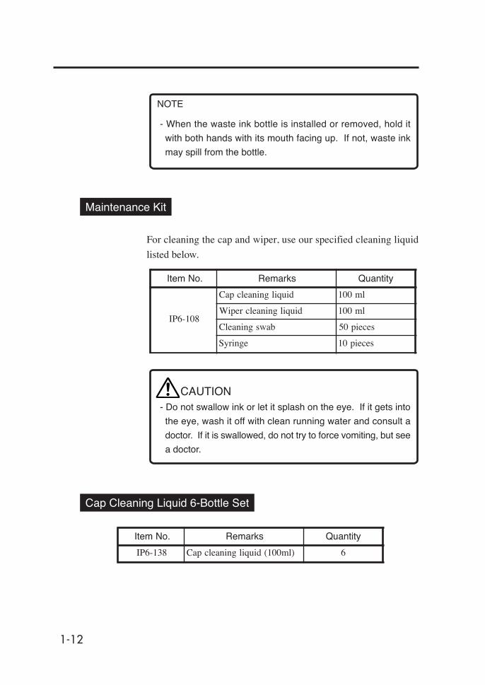
Item No. Remarks Quantity
IP6-138 Cap cleaning liquid (100ml) 6
Cap Cleaning Liquid 6-Bottle Set
Maintenance Kit
For cleaning the cap and wiper, use our specified cleaning liquid
listed below.
Item No. Remarks Quantity
IP6-108
Cap cleaning liquid 100 ml
Wiper cleaning liquid 100 ml
Cleaning swab 50 pieces
Syringe 10 pieces
- Do not swallow ink or let it splash on the eye. If it gets into
the eye, wash it off with clean running water and consult a
doctor. If it is swallowed, do not try to force vomiting, but see
a doctor.
CAUTION
NOTE
- When the waste ink bottle is installed or removed, hold it
with both hands with its mouth facing up. If not, waste ink
may spill from the bottle.
1-13
Sec
tion
1 G
ettin
g S
tart
ed (
Bas
ic k
now
ledg
e)
Consumables
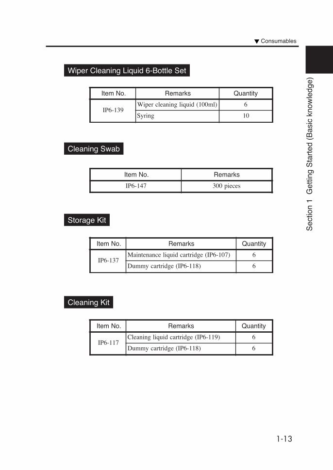
Wiper Cleaning Liquid 6-Bottle Set
Item No. Remarks Quantity
IP6-139Wiper cleaning liquid (100ml) 6
Syring 10
Storage Kit
Cleaning Kit
Item No. Remarks Quantity
IP6-117Cleaning liquid cartridge (IP6-119) 6
Dummy cartridge (IP6-118) 6
Item No. Remarks Quantity
IP6-137Maintenance liquid cartridge (IP6-107) 6
Dummy cartridge (IP6-118) 6
Cleaning Swab
Item No. Remarks
IP6-147 300 pieces

1-14
Head Cleaning Sheet
Liner
Item No. Remarks Quantity
IP6-161 Liner 1 piece
Item No. Remarks Quantity
IP6-148 Head cleaning sheet 6 sheets

1-15
Sect
ion
1 G
ettin
g St
arte
d (B
asic
kno
wle
dge)
External Views, Part Names, and Functions
This section shows external views of the printer and names of
printer parts, and describes their functions.
Front View (Feeding Side)
(1) Operation panel The lamps and LCD, which indicate the printer status, and keys forsetting functions are located on the operation panel. (⇒See page 1-18)
(2) Heater control panel The keys for setting heater temperature are located on the heatercontrol panel. (⇒See page 1-20)
(3) Ink holder Holds the ink cartridge.
(4) Tension bar guide (⇒See page 2-15)
(5) Caster Unlock the caster to move the printer, and locks it to secure theprinter.
(6) Paper pressure alternation lever Alternates media pressure depending on the media thickness.(⇒See page 2-65)
(7) Pressure roller up/down lever Presses down and releases media inserted in the feeding unit.
(8) Feed direction switch1 (⇒See page 2-16)
(9) Take-up Switch (⇒See page 2-16)
(10) Feed Switch (⇒See page 2-16)
(11) Sub scroller (⇒See page 2-21)
(12) Footswitch connector Connects the footswitch (option). (⇒See page 1-20)
Lock Unlock
(1)
(7)
(2)
Main scroller
(5)
(6)
(3)
(3)
(4) (8)
(4)
(9)(10)
(12)
(11)
1-16
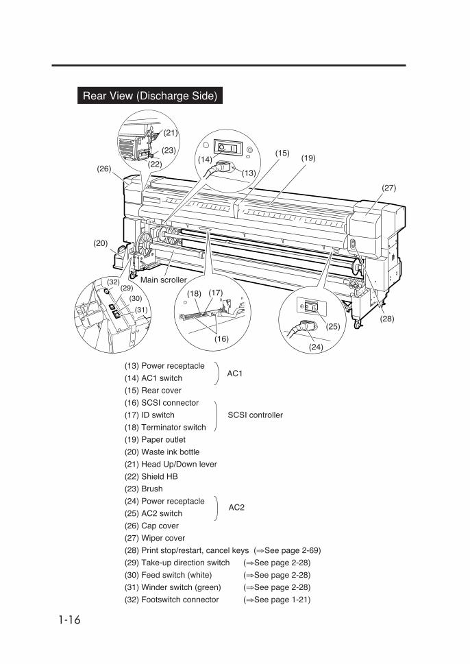
(13) Power receptacle
(14) AC1 switch
(15) Rear cover
(16) SCSI connector
(17) ID switch SCSI controller
(18) Terminator switch
(19) Paper outlet
(20) Waste ink bottle
(21) Head Up/Down lever
(22) Shield HB
(23) Brush
(24) Power receptacle
(25) AC2 switch
(26) Cap cover
(27) Wiper cover
(28) Print stop/restart, cancel keys (⇒See page 2-69)
(29) Take-up direction switch (⇒See page 2-28)
(30) Feed switch (white) (⇒See page 2-28)
(31) Winder switch (green) (⇒See page 2-28)
(32) Footswitch connector (⇒See page 1-21)
RearRear View (Discharge Side)
(17)
(25)
(29)
(16)
AC2
(26)
(20)
(15)(19)
(27)
(28)
AC1
(24)
(18)
(14)
(13)
(30)
(31)
(32) Main scroller
(21)
(23)
(22)

1-17
Sect
ion
1 G
ettin
g St
arte
d (B
asic
kno
wle
dge)
Heater Å
The printer has three built-in heaters for fixing and stabilizing the
print image on the print media.
(1) Front heater (Front) Preheats the media.
(2) Print heater (Rear) Infiltrates ink into the media and fixes ink.
(3) Rear heater (Finish) Dries ink and stabilizes print image.
* The three heaters are controlled separately.
The heater temperature can be controlled from the operation panel and host
PC (RIP).
(⇒See page 2-60 “Changing Heater Control Setting Temperature”)
WARNING- Heaters become hot.
NEVER touch the heaters. Doing so could cause a
burn.
External Views, Part Names, and Functions
Media
Main scroller
Paper feed
direction
Media outlet sideHead
Tension bar
Media inlet side
(1) (2) (3)
1-18
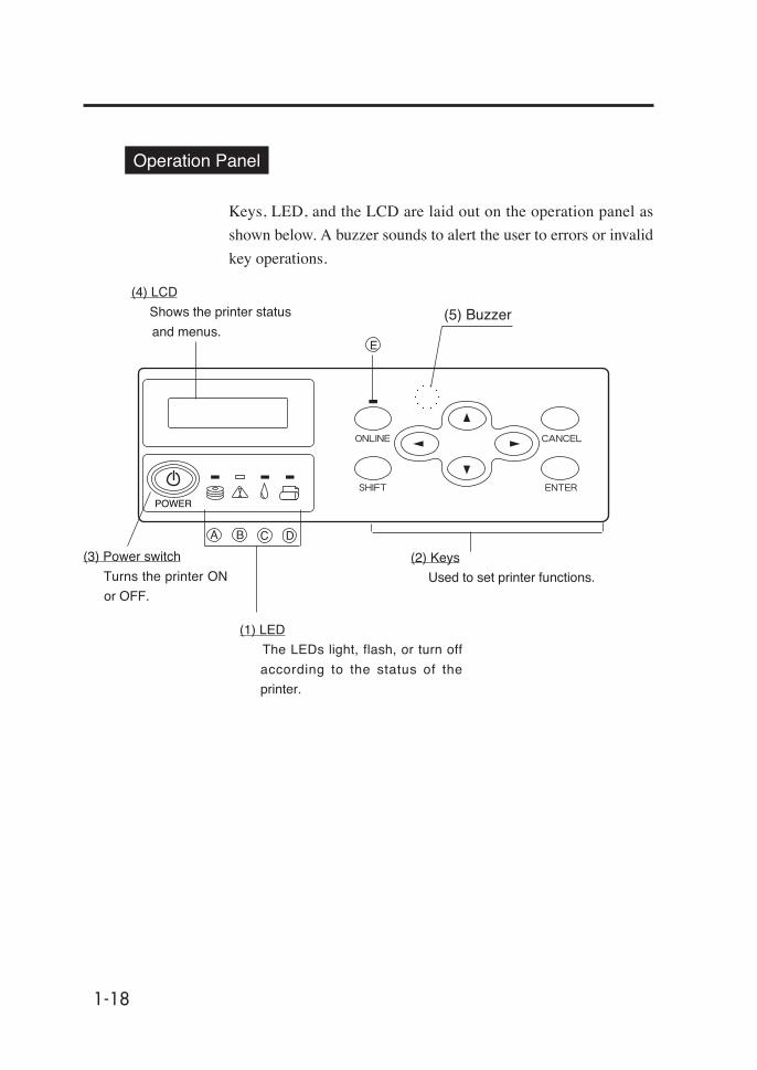
Operation Panel
Keys, LED, and the LCD are laid out on the operation panel as
shown below. A buzzer sounds to alert the user to errors or invalid
key operations.
(3) Power switch
Turns the printer ON
or OFF.
(2) Keys
Used to set printer functions.
(4) LCD
Shows the printer status
and menus.
(1) LED
The LEDs light, flash, or turn off
according to the status of the
printer.
B C D
E
A
(5) Buzzer

1-19
Sect
ion
1 G
ettin
g St
arte
d (B
asic
kno
wle
dge)rebmuN emaN noitcnuF
)1(DEL
DELataD)A()neerg(
.etatsnoitpeceratadehtswohSretupmocehtmorfdeviecergnieberaataD:gnihsalF-
deviecergnieberaatadoN:ffO-
DELrorrE)B()egnaro(
.derruccosahrorrenarehtehwsetacidnIderruccosahrorrenA:nO-
)rorretuoemitredniW(etatsgninraW:gnihsalF-).derruccosahrorreoN(lamroN:ffO-
DELknI)C()neerg(
.gninrawasetacidniroegirtrackninasierehtrehtehwswohS.tneserperasegdirtracknillA:nO-
).tuonursahsknirolocehtfoenO(.tuogninnursiknI:gnihsalF-).tuonursahsknirolocehtfoenO(knioN:ffO-
DELaideM)D()neerg(
.tessiaidemrehtehwswohS).tessiteehstucrorepaplloR(.tessiaideM:nO-
).tessiteehstucronrepapllorrehtieN(aidemoN:ffO-
DELenilnO)E()neerg(
.enilfforoenilnosiretnirpehtrehtehwswohSenilnO:nO-
edomesuapenilnO:gnihsalF-enilffO:ffO-
)2(yeK
yekENILNO .setatsenilffodnaenilnoneewtebsehctiwS
yekTFIHSlevelunemehtsehctiws(tupniretemaraprofyekyrailixuanasadesU
.)yalpsid
yekLECNAC .retemaraptupninaslecnaC
yekRETNE .retemarapasretnerounemastceleS
yek
unemehtsehctiwsropuorgunemehtstceleS.)nwod/purebmun,noitceles(
yek
yek
yek
)3(hctiwsrewoP
hctiwSrewoP .FFOroNOretnirpehtnrutotdesU
)4(DCL
DCL
,sretcarahcciremunahplahtiwsutatsrosegassemretnirpswohSlacihcrareihaevahsuneM.)senilowt,stigid61(slobmysro,anakatak
ro,,,htiwunemhcaesseccA.erutcurts.yek
)5(rezzuB
rezzuB .rorrenaforotarepoehtyfitonotmralanasdnuoS
Functions of LCD, LED and keys
External Views, Part Names, and Functions
1-20
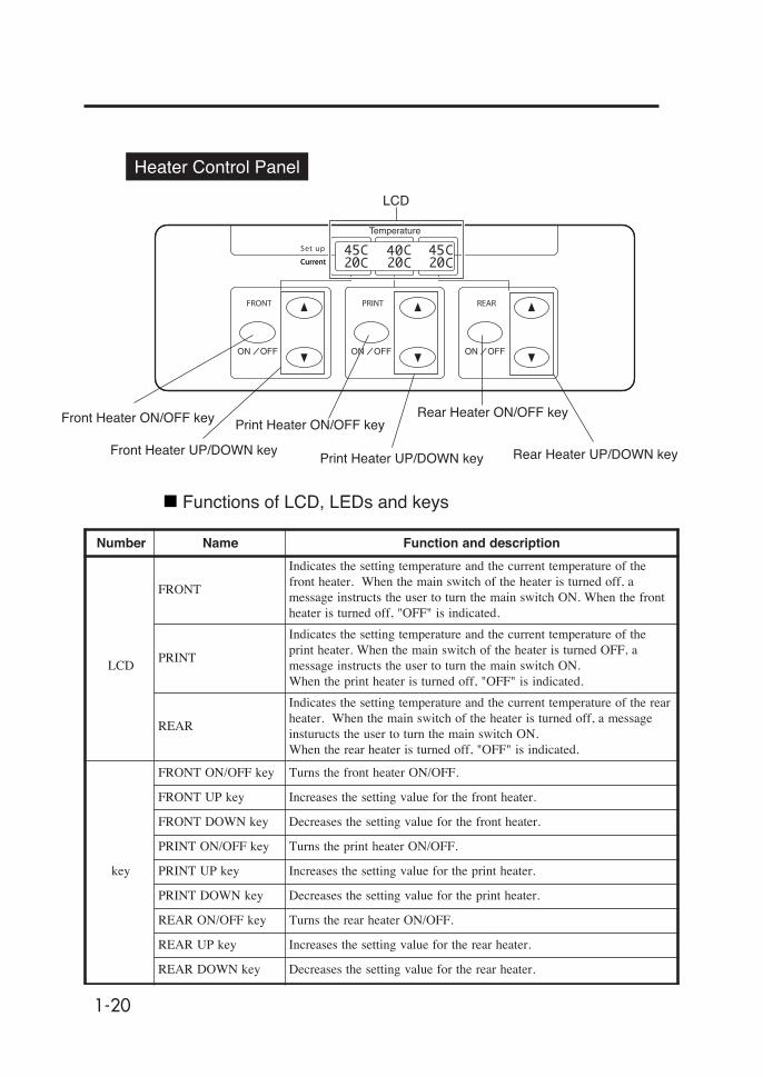
Heater Control Panel Å
Functions of LCD, LEDs and keys
LCD
Print Heater ON/OFF key
Print Heater UP/DOWN key
Front Heater ON/OFF key
Front Heater UP/DOWN key
Rear Heater ON/OFF key
Rear Heater UP/DOWN key
Number Name Function and description
LCD
FRONT
Indicates the setting temperature and the current temperature of thefront heater. When the main switch of the heater is turned off, amessage instructs the user to turn the main switch ON. When the frontheater is turned off, "OFF" is indicated.
Indicates the setting temperature and the current temperature of theprint heater. When the main switch of the heater is turned OFF, amessage instructs the user to turn the main switch ON.When the print heater is turned off, "OFF" is indicated.
REAR
Indicates the setting temperature and the current temperature of the rearheater. When the main switch of the heater is turned off, a messageinsturucts the user to turn the main switch ON.When the rear heater is turned off, "OFF" is indicated.
key
FRONT ON/OFF key Turns the front heater ON/OFF.
FRONT UP key Increases the setting value for the front heater.
FRONT DOWN key Decreases the setting value for the front heater.
PRINT ON/OFF key Turns the print heater ON/OFF.
PRINT UP key Increases the setting value for the print heater.
PRINT DOWN key Decreases the setting value for the print heater.
REAR ON/OFF key Turns the rear heater ON/OFF.
REAR UP key Increases the setting value for the rear heater.
REAR DOWN key Decreases the setting value for the rear heater.

1-21
Sect
ion
1 G
ettin
g St
arte
d (B
asic
kno
wle
dge)
Dryer 100 (Option)
The dryer 100 dries the output media.
Footswitch (Option)
Operates the functions of the take-up switch and feed switch of the
paper feeder and the winder by foot.
SCSI Cable (9 m) (Option)
Connects the printer to the host PC. It is longer than the standard
cable by 3 m.
Main Scroller (Option)
Used in common for the feeder and the winder.
Sub Scroller (Option)
Used for the liner and sub roll.
Exhaust Attachment 100 (Option)
Attached to the printer to mount an exhaust duct.
External Views, Part Names, and Functions

1-22
Tension Bar Set (Option)
Peeling Bar Set (Option)
Peels sticky media.
Dual Roll Kit (Option)
Additional parts to feed dual rolls.
Edge Guide (Option)
Retains the media when the liner is used.
PS RIP (PhotoPrint 4 DX) (Option)
PS RIP (PhotoPrint 4 Server) (Option)
RIP software for the IP-6900.

2-1
Sect
ion
2 B
asic
Ope
ratio
ns
Contents of this section
Section 2 Basic Operations
Connecting to a Computer
Turning the Power ON/OFF
Installing/Removing the Media
Replacing Ink Cartridges
Replacing the Waste Ink Bottle
Tension Bar Length Adjustment
Head Cleaning "CLEANING"
Paper Feed "FEED"
Using the Origin Point Setting Function
Changing Heater Control Setting Temperature
Using the Media Pressure Alternation Lever
Using the Head Up/Down Lever
Using the Media Edge Guard
Using the Print Pause/Restart and Cancel Keys
Inspection & Maintenance
2-2
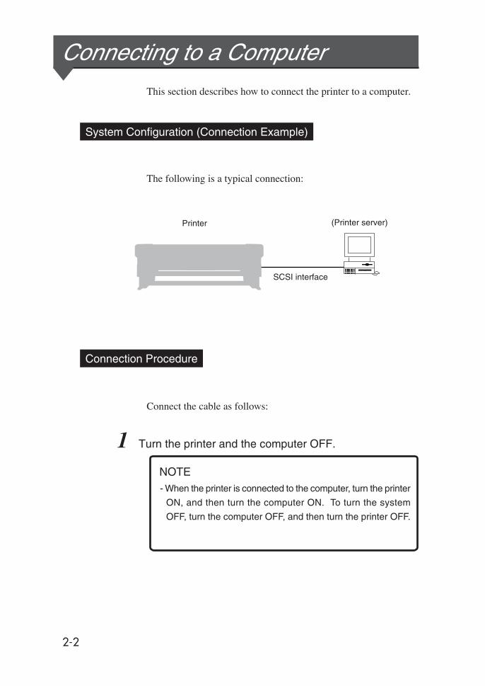
Connecting to a ComputerThis section describes how to connect the printer to a computer.
System Configuration (Connection Example)
The following is a typical connection:
Connection Procedure
Connect the cable as follows:
1 Turn the printer and the computer OFF.
Printer (Printer server)
SCSI interface
NOTE- When the printer is connected to the computer, turn the printer
ON, and then turn the computer ON. To turn the system
OFF, turn the computer OFF, and then turn the printer OFF.

2-3
Sect
ion
2 B
asic
Ope
ratio
ns
3 Set the SCSI ID switch on the rear of the printer.
- The ID number must be unique in the SCSI chain. (Initial
setting: 4)
SCSI ID switch
Set the SCSI ID number with a small
slotted screwdriver. (Initial ID value: 4)
2 Connect a SCSI cable to either of the SCSI connectors
on the rear of the printer.
Connecting to a Computer
NOTE
(It can be connected to either of two SCSI
connectors.)
NOTE
- Use a dedicated SCSI cable (68-68-pin, 6 m) or optional
SCSI cable (68-68-pin, 9m).
If any other cable is used, the radio wave level may
increase, in particularly the printer might not satisfy FCC
and CE regulations.
SCSI connector
2-4
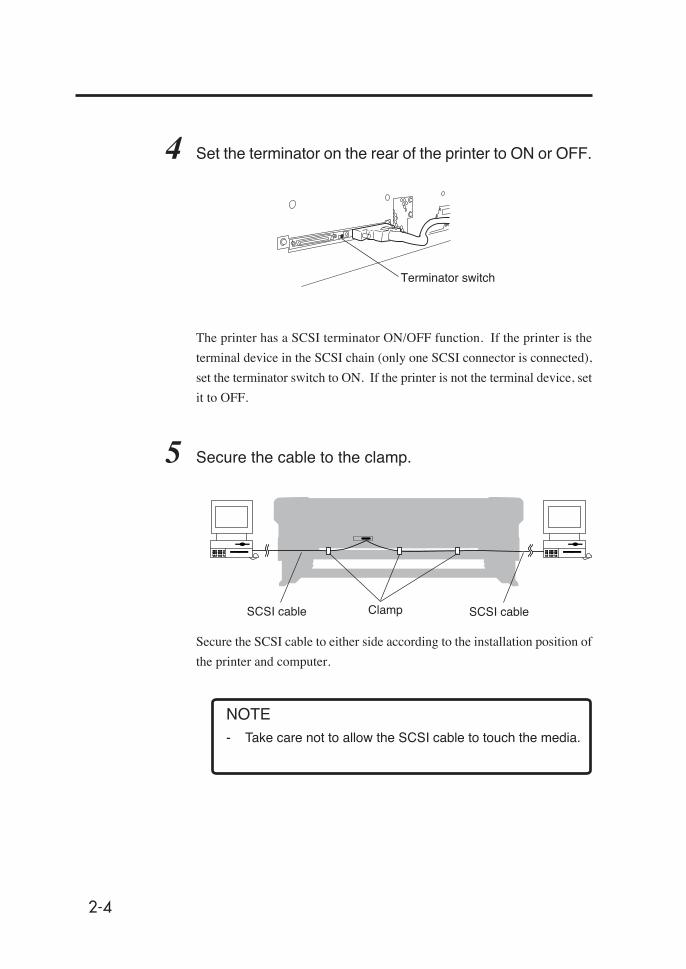
4 Set the terminator on the rear of the printer to ON or OFF.
The printer has a SCSI terminator ON/OFF function. If the printer is the
terminal device in the SCSI chain (only one SCSI connector is connected),
set the terminator switch to ON. If the printer is not the terminal device, set
it to OFF.
5 Secure the cable to the clamp.
Secure the SCSI cable to either side according to the installation position of
the printer and computer.
Terminator switch
NOTE- Take care not to allow the SCSI cable to touch the media.
SCSI cableSCSI cable Clamp

2-5
Sect
ion
2 B
asic
Ope
ratio
ns
Turning the Power ON/OFFThis printer has two power supply systems. Be careful that both are
200V.
AC1 switch
The AC1 switch is located on the printer rear (left side).
AC2 switch
The AC2 switch is located on the printer rear (right side).
NOTES- When the printer is connected to the computer, turn the
printer ON, and then turn the computer ON. To turn the
system OFF, turn the computer OFF, and then turn the
printer OFF.
- Turn the computer ON after the printer is in the online state.
Printer rear (Right side)
AC1
Printer rear (left side)
AC2

2-6
Turning the Power ON
<Power ON Procedure>
1 Turn the AC1 switch on the left rear of the printer OFF
(0), and plug one end of the supplied power cable into the
AC1 socket. Insert the other power plug of the cable into
an electrical outlet.
2 Turn the AC1 switch on the left rear of the printer ON (1).
Printer switch
OFF (0)
Socket
Printer switch
ON (1)
Socket

2-7
Sect
ion
2 B
asic
Ope
ratio
ns
Turning the Power ON/OFF
3 Turn the AC 2 switch on the right rear of the printer OFF
(0), and plug one end of the supplied power cable into the
AC 2 socket. Insert the other power plug of the cable into
an electrical outlet.
4 Turn the AC 2 switch on the right rear of the printer ON (1).
Power cable
NOTES- Do not use a power cable other than the one specified for
this printer.
- The supplied power cable is for 200VAC. The shape of the
plug is different from the plug for 100VAC.
Printer switch OFF (0)
Socket
Printer switch ON (1)
CAUTION- Fix the power cable in place using a clamp. If this is not
done, the power cable can be wound up in the scroller,
possibly causing electric shock and damage to the
equipment.
2-8
Booting
PRINT READY
ROLL : 104 / PAPER
INITIALIZING
WAIT A MOMENT
If a 104" media roll is used
CHECK AC2
POWER OFF / ON
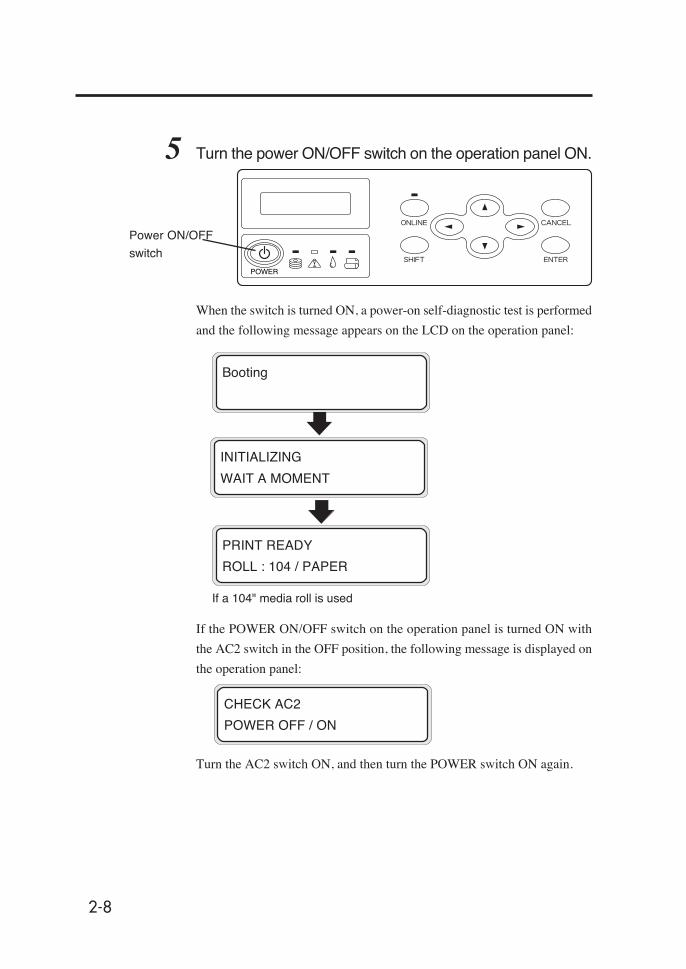
5 Turn the power ON/OFF switch on the operation panel ON.
When the switch is turned ON, a power-on self-diagnostic test is performed
and the following message appears on the LCD on the operation panel:
Power ON/OFF
switch
If the POWER ON/OFF switch on the operation panel is turned ON with
the AC2 switch in the OFF position, the following message is displayed on
the operation panel:
Turn the AC2 switch ON, and then turn the POWER switch ON again.
2-9
Sect
ion
2 B
asic
Ope
ratio
ns
Turning the Power ON/OFF
NOTE- Turn the printer OFF while “PRINT READY” is displayed on
the LCD panel except in an emergency.
Do not turn the printer OFF while “INITIALIZING” or
“CLEANING” is displayed on the LCD panel to avoid dripping
of the ink and damage of the head. Saved parameters may
be lost.
- If the fan does not run or the operation panel lamp does notlight when the AC1 switch and power ON/OFF switch on theoperational panel are turned ON, the power supply may befaulty.
- If an error is detected during the self-diagnostic test at powerON, an error message appears on the LCD. See Section 5,Troubleshooting, and take appropriate action.
HINT

2-10
Turning the Power OFF 1
1 To turn the power OFF without fill cap operation,
simultaneously press the power ON/OFF switch and the
key on the operation panel continuously for 2 to 3
seconds.
The above message is displayed on the LCD to indicate that the
shutdown process is in progress. After the process ends, the power
is turned OFF.
Use this procedure to turn the power OFF to recover from an error
or communication disorder.
Turning the Power OFF 2
1 Turn the power ON/OFF switch on the operation panel
OFF for a couple of seconds.
The above message is displayed on the LCD to indicate that the
shutdown process is in progress. After the process ends, the power
is turned OFF.
At shutdown, fill cap operation (filling the cap with ink) is executed
to maintain the head in good condition.
*For restarting the printer within 20 hours
SHUTDOWN
WAIT A MOMENT
SHUTDOWN
WAIT A MOMENT
*When turning the printer OFF for 20 hours or more

2-11
Sect
ion
2 B
asic
Ope
ratio
ns
- The AC1 switch and AC2 switch on the rear of the printer
should be used only when the printer is turned OFF
completely in order to move it, connect it with a computer,
install or maintain its parts.
- When turning the power ON/OFF switch OFF, wait for at
least ten seconds, then turn it ON again.
- The printer automatically performs fill cap operation to
maintain good head condition after the first 20 hours in the
standby state and every 3 days thereafter.
It is recommended to keep the printer ON.
- The fill cap operation is effective for protecting the head,
but it consumes extra ink.
CAUTION
Turning the Power ON/OFF

2-12
Installing/Removing the MediaThe media can be fed to the printer in the following five ways:
- "MAIN" : Normal feed from the main scroller
- "SUB" : Feed from sub scroller
- "DUAL" : For dual roll printing
- "FACE or BACK" : For duplex printing (⇒ See Section 4)
- "SHEET" : Feed of cut sheet
This section explains MAIN, SUB, and CUT SHEET feeds.
Installing Main Scroller
1 Place the media on the table.
If a cart is used, it should be the
recommended model. (For further
information, please contact us.)
2 Adjust the roll spacer position according to the media
width.
- The roll spacer prevents the paper tube from sagging in
the center by the weight of media.
(1) Remove the two screws, and move the roll
spacer so that it comes to the center of the
media. The spacer is locked at three places with
the screws.
Roller spacer
HINT
Do not move this roller spacer
Main scroller

2-13
Sect
ion
2 B
asic
Ope
ratio
ns
3 Pass the scroller through the paper tube, determine the
distance between the media edge and flange, and lock
the main scroller.(1) Confirm the media winding direction, and
pass the scroller through the paper tube.
(2) Using the media positioning tool, determine
the distance between the media edge and flange.
(3) Rotate the handwheel clockwise until it
stops, then lock the main scroller.
4 Engage the flange spacer with the flange stopper, and
install them.(1) Push in the toothed flange spacer until it
stops.
(2) Install the flange stopper by aligning it to the
hook of the flange spacer, then tighten the knob
to lock.
(3) Shift the tension bar guide to avoid
interference.
Outer take-up Inner take-up
Handwheel
Flange stopper
Knob
Flange spacer
Media positioning
tool
Installing/Removing the Media
2-14
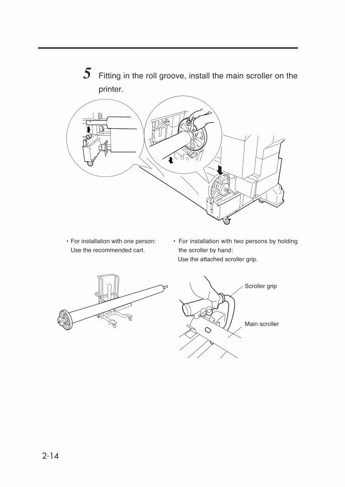
5 Fitting in the roll groove, install the main scroller on the
printer.
• For installation with one person:
Use the recommended cart.
• For installation with two persons by holding
the scroller by hand:
Use the attached scroller grip.
Scroller grip
Main scroller

2-15
Sect
ion
2 B
asic
Ope
ratio
ns
Media Setting
1 Move the tension bar guide to the position of the label,
then fix it in place with the screw below the guide.
2 Shift the media edge guards to both sides so that they
are not hidden under the media.
3 Lift the pressure roller up/down lever.
Installing/Removing the Media
Pressure roller up/
down lever
Tension bar guide
2-16
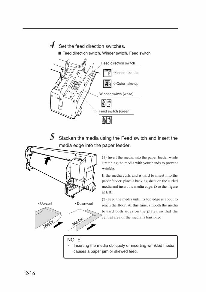
4 Set the feed direction switches.
5 Slacken the media using the Feed switch and insert the
media edge into the paper feeder.
(1) Insert the media into the paper feeder while
stretching the media with your hands to prevent
wrinkle.
If the media curls and is hard to insert into the
paper feeder, place a backing sheet on the curledmedia and insert the media edge. (See the figure
at left.)
(2) Feed the media until its top edge is about to
reach the floor. At this time, smooth the media
toward both sides on the platen so that the
central area of the media is tensioned.
- Inserting the media obliquely or inserting wrinkled media
causes a paper jam or skewed feed.
Feed direction switch
Winder switch (white)
Feed switch (green)
■ Feed direction switch, Winder switch, Feed switch
�Inner take-up
�Outer take-up
Media Media
• Up-curl • Down-curl
NOTE

2-17
Sect
ion
2 B
asic
Ope
ratio
ns
Installing/Removing the Media
6 Using the Winder switch on the feeder side, rewind the
media so that the media edge protrudes from the rear
cover a little.
- Work in step 6 is important for correct setting of the me-
dia.
7 Push the pressure roller up/down lever down.
Pressure roller up/
down lever
HINT

2-18
8 Set the media edge guard, and close the rear cover.
(1) Close the rear cover.
(2) Confirm the media edge guard position
and press the key, and the media
width checking operation will start.
9 Select the media feed position.
From the parameters, select "MAIN"
with or key.
Press the key to change the setting.
Press the key to hold the last setting as it is.
10 Select the base function.
Select "USED" if the "Origin Point
Setting Function (⇒ See page 2-58)" is
used.
Media edge guard
MEDIA POSITION
SELECT: MAIN
CLOSE REAR COVER
CHECK EDGE GUARD
✽OK?
BASE FUNCTION
SELECT: NOT USED

2-19
Sect
ion
2 B
asic
Ope
ratio
ns
Press the key to enter the NEW PAPER ENTRY menu.
Operation for a new paper entry is the same as operation for media
entry from the ENTRY menu. (⇒ See Section 3, Entry Menu)
Press the key to return to the SELECT PAPERTYPE menu.
SELECT PAPERTYPE
PAPER : TYPE01
When registering a new media type
SELECT PAPERTYPE
NEW PAPER ENTRY
(Only registered media types can be
selected.)
- The base function selecting menu may not be displayed
depending on the version of the firmware. To use the base
function, select "SELECT: MAIN B" for the media feed
selection.
11 Select the media type.
Press the key to change the setting.
Press the key to leave the setting as it is.
SELECT PAPERTYPE
PAPER : PAPER
Select a media type with the and
keys.
SELECT PAPERTYPE
PAPER : PAPER
Installing/Removing the Media
HINT
NOTE

2-20
12 Using the feed switch on the feeder side, slacken the
media and install the tension bar.
Adjust the tension bar length according to the
media width. (See page 2-53, Tension Bar
Length Adjustment.)
• This message is skipped if cut media is
used.
• The next operation will not start if the
media slack is inadequate.
13 Media setting operation will start automatically.
• If the operation terminates normally,
the printer returns to the online or offline
state.
• If it terminates unsuccessfully, an error
message will be displayed.
Go back to step 5.
CHECK BUFFER
✽OK?
PREPARING PAPER
WAIT A MOMENT
2-21
Sect
ion
2 B
asic
Ope
ratio
ns
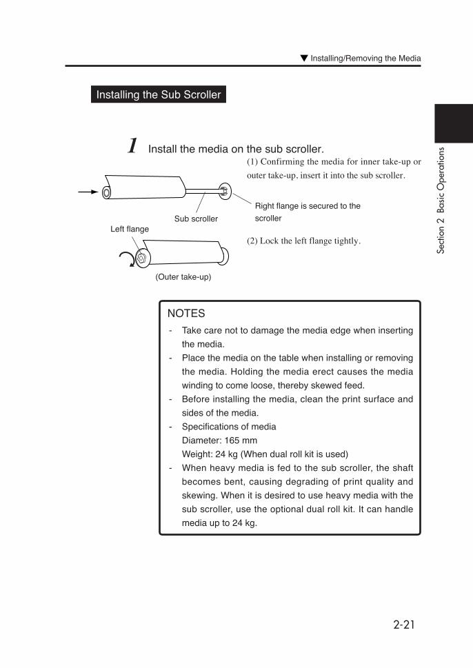
Installing the Sub Scroller
1 Install the media on the sub scroller.(1) Confirming the media for inner take-up or
outer take-up, insert it into the sub scroller.
(2) Lock the left flange tightly.
- Take care not to damage the media edge when inserting
the media.
- Place the media on the table when installing or removing
the media. Holding the media erect causes the media
winding to come loose, thereby skewed feed.
- Before installing the media, clean the print surface and
sides of the media.
- Specifications of media
Diameter: 165 mm
Weight: 24 kg (When dual roll kit is used)
- When heavy media is fed to the sub scroller, the shaft
becomes bent, causing degrading of print quality and
skewing. When it is desired to use heavy media with the
sub scroller, use the optional dual roll kit. It can handle
media up to 24 kg.
Installing/Removing the Media
Sub scroller
Right flange is secured to the
scrollerLeft flange
(Outer take-up)
NOTES

2-22
Installing the Sub Scroller on the Printer
1 Shift the media edge guards toward both sides.
2 Lift the pressure roller up/down lever.
3 Place the sub scroller on the sub scroller holder.
4 Insert the media into the feeder, and feed the media until
its top edge is about to reach the floor.
Sub scroller
Sub scroller holder
2-23
Sect
ion
2 B
asic
Ope
ratio
ns
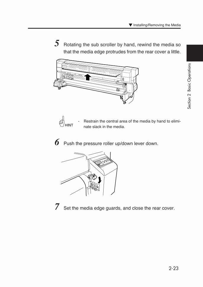
5 Rotating the sub scroller by hand, rewind the media so
that the media edge protrudes from the rear cover a little.
- Restrain the central area of the media by hand to elimi-nate slack in the media.
6 Push the pressure roller up/down lever down.
7 Set the media edge guards, and close the rear cover.
Installing/Removing the Media
HINT
2-24
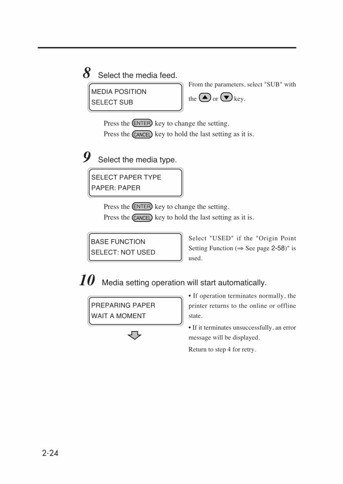
8 Select the media feed.From the parameters, select "SUB" with
the or key.
Press the key to change the setting.
Press the key to hold the last setting as it is.
9 Select the media type.
Press the key to change the setting.
Press the key to hold the last setting as it is.
Select "USED" if the "Origin Point
Setting Function (⇒ See page 2-58)" is
used.
10 Media setting operation will start automatically.
• If operation terminates normally, the
printer returns to the online or offline
state.
• If it terminates unsuccessfully, an error
message will be displayed.
Return to step 4 for retry.
BASE FUNCTION
SELECT: NOT USED
MEDIA POSITION
SELECT SUB
SELECT PAPER TYPE
PAPER: PAPER
PREPARING PAPER
WAIT A MOMENT
2-25
Sect
ion
2 B
asic
Ope
ratio
ns
Installing/Removing the Media
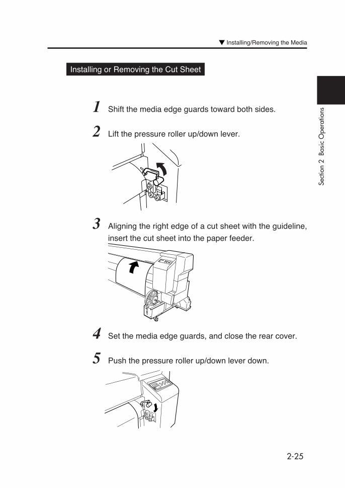
Installing or Removing the Cut Sheet
1 Shift the media edge guards toward both sides.
2 Lift the pressure roller up/down lever.
3 Aligning the right edge of a cut sheet with the guideline,
insert the cut sheet into the paper feeder.
4 Set the media edge guards, and close the rear cover.
5 Push the pressure roller up/down lever down.

2-26
6 Select the media feed.From the parameters, select "SHEET"
with the or key.
Press the key to change the setting.
Press the key to hold the last setting as it is.
7 Select the media type.
Press the key to change the setting.
Press the key to hold the last setting as it is.
8 Media setting operation will start automatically.• If the operation terminates normally,
the printer returns to the online or offline
state.
• If it terminates unsuccessfully, an error
message will be displayed.
Return to step 1 for retry.
To remove the cut sheet, lift the pressure roller up/down lever
and remove it.
MEDIA POSITION
SELECT: SHEET
SELECT PAPERTYPE
PAPER: PAPER
PREPARING PAPER
WAIT A MOMENT
REMOVE
2-27
Sect
ion
2 B
asic
Ope
ratio
ns
Installing/Removing the Media
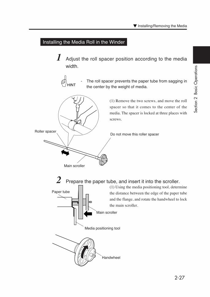
Installing the Media Roll in the Winder
1 Adjust the roll spacer position according to the media
width.
- The roll spacer prevents the paper tube from sagging inthe center by the weight of media.
(1) Remove the two screws, and move the roll
spacer so that it comes to the center of the
media. The spacer is locked at three places with
screws.
2 Prepare the paper tube, and insert it into the scroller.(1) Using the media positioning tool, determine
the distance between the edge of the paper tube
and the flange, and rotate the handwheel to lock
the main scroller.
HINT
Roller spacer
Main scroller
Do not move this roller spacer
Media positioning tool
Paper tube
Main scroller
Handwheel
2-28
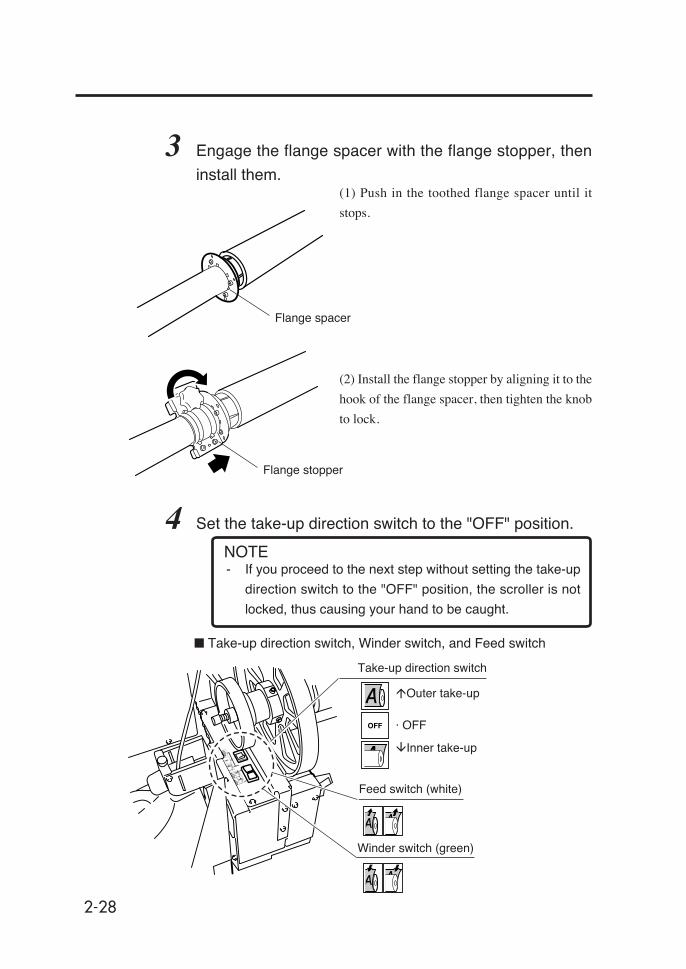
3 Engage the flange spacer with the flange stopper, then
install them.(1) Push in the toothed flange spacer until it
stops.
(2) Install the flange stopper by aligning it to the
hook of the flange spacer, then tighten the knob
to lock.
4 Set the take-up direction switch to the "OFF" position.
- If you proceed to the next step without setting the take-up
direction switch to the "OFF" position, the scroller is not
locked, thus causing your hand to be caught.
Flange spacer
Flange stopper
■ Take-up direction switch, Winder switch, and Feed switch
Take-up direction switch
Feed switch (white)
Winder switch (green)
�Outer take-up
· OFF
�Inner take-up
NOTE
2-29
Sect
ion
2 B
asic
Ope
ratio
ns
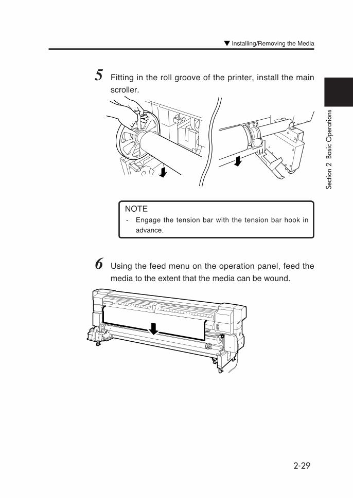
5 Fitting in the roll groove of the printer, install the main
scroller.
- Engage the tension bar with the tension bar hook in
advance.
6 Using the feed menu on the operation panel, feed the
media to the extent that the media can be wound.
Installing/Removing the Media
NOTE

2-30
7 Secure the fed media to the paper tube.
(1) Confirm the take-up direction, and secure
the media with adhesive tapes at three places;
first secure the center so that it is straight, and
then secure both sides.
- Make sure that the direction of the attaching tape on the
take-up side matches the take-up direction setting (outer
side rewind/ inner side rewind).
- If the media is attached to the paper tube at an angle it will
be fed at an angle, so use caution.
8 Adjust the tension bar guide position according to the
take-up direction.
Outer take-up :Paper is wound so that theprint surface comes inside.
Inner take-up :Paper is wound so that theprint surface comes outside.
Tapes
Tension bar guide
Tension bar guide
■ Inner take-up ■ Outer take-up
NOTES
2-31
Sect
ion
2 B
asic
Ope
ratio
ns
Installing/Removing the Media
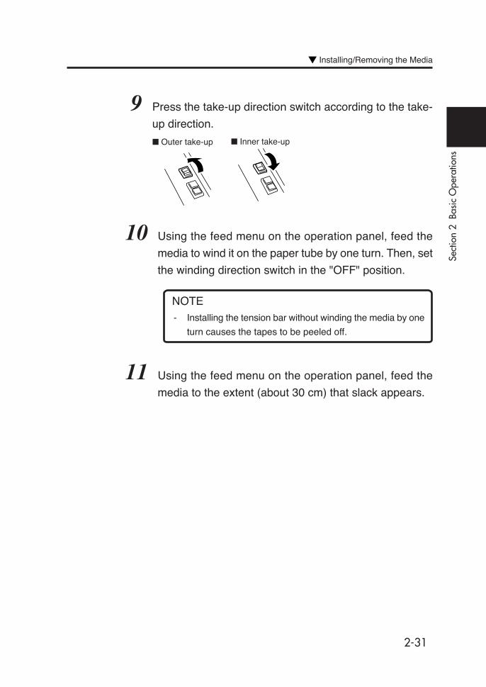
9 Press the take-up direction switch according to the take-
up direction.
10 Using the feed menu on the operation panel, feed the
media to wind it on the paper tube by one turn. Then, set
the winding direction switch in the "OFF" position.
- Installing the tension bar without winding the media by one
turn causes the tapes to be peeled off.
11 Using the feed menu on the operation panel, feed the
media to the extent (about 30 cm) that slack appears.
■ Outer take-up ■ Inner take-up
NOTE

2-32
12 Install the tension bar in a slack part of the media.
Tension bar guideTension bar
- Attach the tension bar so that it is gripped between the tension bar
guide and the sensor arm.
- Adjust the guide position so that the tension bar guide is gripped
between the 2 flanges.
NOTE
Tension bar guideTension bar
Main scrollerMedia
Tension bar hook
Tension barguide
Tension bar
Flange Sensor arm
Flange fortake-up

2-33
Sect
ion
2 B
asic
Ope
ratio
ns
13 Move the flange according to the media width.
14 Press the take-up direction switch according to the take-
up direction.
Installing/Removing the Media
Fixing ringsFlange for take-up

2-34
Removing the Paper Roll from the Printer
1 Remove the tension bars on the media feed side and
outlet side.
2 Cut the media.
3 Lift the pressure roller up/down lever.
4 Using the winder switch on the feed side, wind the media.
5 Place the media roll on the table.
6 Remove the flange stopper and the flange spacer.
Pressure roller up/down lever
Flange stopper Flange spacer
- A net is spread out on the feeding side and take-up side paper guides,
respectively so that the media will not adhere to the guides. Do not
remove these nets.
- When cutting the media, be careful not to damage the paper guide
net.
NOTES

2-35
Sect
ion
2 B
asic
Ope
ratio
ns
7 Remove the scroller.(1) Rotate the handwheel counterclockwise.
(2) When a gap appears between the handwheel
and scroller shaft, remove the scroller.
- Do not touch the scroller hook.
NOTE
Replacing Media on Main Scroller
1 The following message appears on the LCD screen.
2 Replace the media following "Installing/Removing the
Media."
Replacing Media on Sub Scroller
1 The following message appears on the LCD screen.
- If the bottom edge of the media on the sub scroller has
been secured with tapes, the media end is detected with a
jam error. In this case, cleaning is not executed.
- If the media is not secured with tapes, the media end is
detected by the feed sensor.
Replacing Jammed Media Roll
See “Clearing Media Jam” in Section 6, Troubleshooting.
LIFT LEVER
SET PAPER
NOTES
Installing/Removing the Media

2-36
2 Set the printer to OFFLINE mode.
(Press the key)
3 Press the key, and then the key to display a
feed adjustment pattern.
#FEED PATTERN
✽ROUGH (NORMAL)
Select the print mode you usually use for the media to which the feed
correction value is set.
For details of the print modes, see page 4-2 "Print Modes".
INK ENTRY
PAPER F. ADJ
Feed Correction Value Setting
The feed correction value is changed by the following causes:
• Backing sheet is used/not used
• Print mode is changed
• Pressure is changed by the media pressure alternation
lever
• Winder is used/not used
• Media type
• Media feed path is different
• Feed mode "SEQUENCE 1" or "SEQUENCE 2"
1 Set media of length longer than 1 m.For the feed correction, obtain approximate feed correction value in the
ROUGH mode, and set exact correction value in the DETAIL mode. One
printing requires a media length of 48 to 58 cm in the ROUGH mode, or 27
to 32 cm in the DETAIL mode. (Printing of the feed adjustment pattern can
be cancelled by pressing the key.)
HINT
2-37
Sect
ion
2 B
asic
Ope
ratio
ns
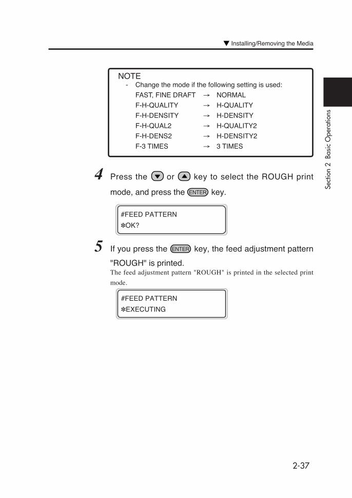
5 If you press the key, the feed adjustment pattern
"ROUGH" is printed.The feed adjustment pattern "ROUGH" is printed in the selected print
mode.
#FEED PATTERN
✽EXECUTING
#FEED PATTERN
✽OK?
4 Press the or key to select the ROUGH print
mode, and press the key.
- Change the mode if the following setting is used:
FAST, FINE DRAFT → NORMAL
F-H-QUALITY → H-QUALITY
F-H-DENSITY → H-DENSITY
F-H-QUAL2 → H-QUALITY2
F-H-DENS2 → H-DENSITY2
F-3 TIMES → 3 TIMES
NOTE
Installing/Removing the Media

2-38
7 Press the key, and then the key to display the
feed correction value entry screen.
#FEED ADJUST
✽100.00%
8 Enter the feed correction value, and press the key.
Adjust the place with the and keys and enter the numeric value
with the and keys.
9 Press the key, and then the key to display the
feed adjustment pattern.
#FEED PATTERN
✽ROUGH (NORMAL)
10 Press the or key to select the DETAIL print
mode.
Select the same pattern as that for ROUGH.
#FEED PATTERN
✽DETAIL (NORMAL)
6 From the printed result, select the approximate feed
correction value.Nine patterns are printed in steps of 0.25% in the range of 99.00% to
101.00%. Select the approximate correction value.
2-39
Sect
ion
2 B
asic
Ope
ratio
ns
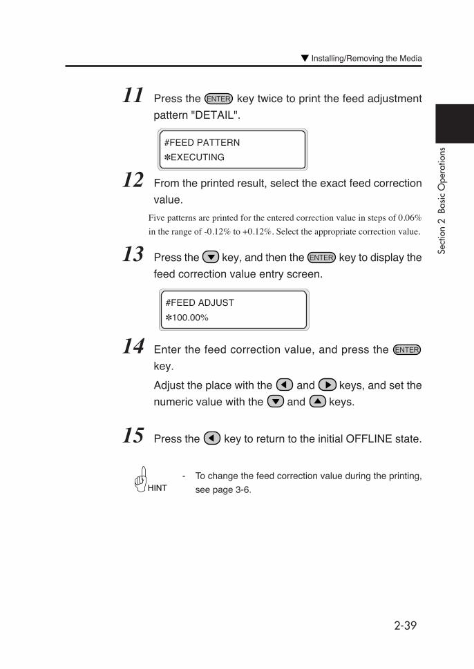
13 Press the key, and then the key to display the
feed correction value entry screen.
#FEED ADJUST
✽100.00%
14 Enter the feed correction value, and press the
key.
Adjust the place with the and keys, and set the
numeric value with the and keys.
15 Press the key to return to the initial OFFLINE state.
- To change the feed correction value during the printing,
see page 3-6.
11 Press the key twice to print the feed adjustment
pattern "DETAIL".
#FEED PATTERN
✽EXECUTING
12 From the printed result, select the exact feed correction
value.
Five patterns are printed for the entered correction value in steps of 0.06%
in the range of -0.12% to +0.12%. Select the appropriate correction value.
HINT
Installing/Removing the Media
2-40
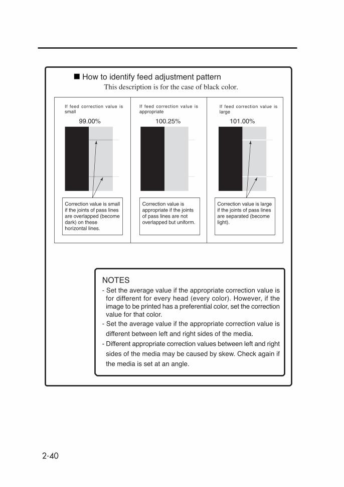
How to identify feed adjustment patternThis description is for the case of black color.
If paper feed adjustmentcorrection value is small
If paper feed adjustmentcorrection value is appropriate
If paper feed adjustmentcorrection value is large
99.00% 100.25% 101.00%
Correction value is small if the joints of pass lines are overlapped (become dark) on these horizontal lines.
Correction value is appropriate if the joints of pass lines are not overlapped but uniform.
Correction value is large if the joints of pass lines are separated (become light).
- Set the average value if the appropriate correction value isfor different for every head (every color). However, if theimage to be printed has a preferential color, set the correctionvalue for that color.
- Set the average value if the appropriate correction value is
different between left and right sides of the media.
- Different appropriate correction values between left and right
sides of the media may be caused by skew. Check again if
the media is set at an angle.
NOTES
If feed correction value issmall
If feed correction value isappropriate
If feed correction value islarge

2-41
Sect
ion
2 B
asic
Ope
ratio
ns
Replacing Ink CartridgesThis section describes how to replace an ink cartridge.
Ink cartridges should be installed in the following four cases:
- If ink has run out
- If an ink cartridge is not installed
- If a 4-color ink cartridge is to be replaced
- If a 6-color ink cartridge is to be replaced
The ink cartridge replacement procedure in each case is explained
below.
Ink Cartridge Replacement Procedure
1 Open the ink cover.
Ink cartridge
NOTES
Ink cover
Push here to open the ink cover.
- Do not remove the ink cartridge in the following cases:
• No power is supplied to the printer due to a power failure
or breaker action.
• An error other than ink end has occurred.
- Depending on the printer status, the ink in the ink box may
spill, causing malfunction.
- Select the offline state if the ink cartridge in which the ink
remains is replaced. (⇒ See Section 3, Ink Menu (5))
For ink replacement during printing, see "Replacing the
cartridge during printing".
- Make sure the ink cartridge is right side up before installing.
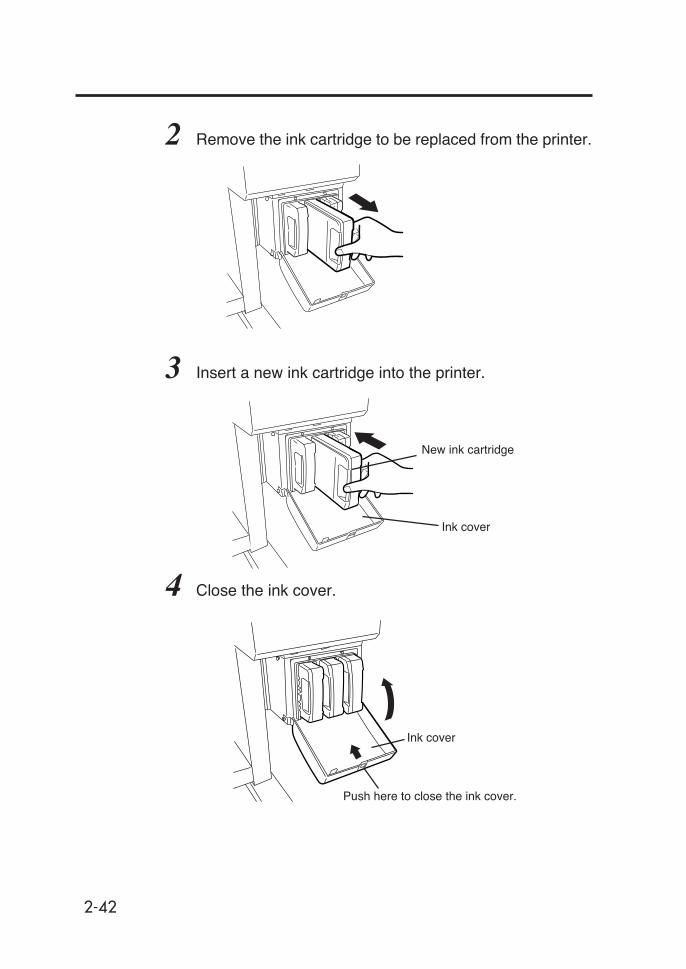
2-42
3 Insert a new ink cartridge into the printer.
4 Close the ink cover.
New ink cartridge
Ink cover
Ink cover
Push here to close the ink cover.
2 Remove the ink cartridge to be replaced from the printer.

2-43
Sect
ion
2 B
asic
Ope
ratio
ns
Replacing an Empty Ink Cartridge
1 The following guidance message appears:
2 Replace the ink cartridge according to the “Ink Cartridge
Replacement Procedure.”
OPEN R INKCOVER
CHANGE XX INK
XX: Ink name
C: CYAN
M: MAGENTA
Y: YELLOW
OPEN L INKCOVER
CHANGE XX INK
XX: Ink name
Bk: BLACK
Lm: LIGHT MAGENTA
Lc: LIGHT CYAN
5 End of ink cartridge replacement.- If replacement ends normally, the printer returns to the offline or online
state.
- If replacement ends in an abnormal manner, an error message will be
displayed.
Go back to step 1 and repeat the procedure.
- The printer continues to print as long as ink remains in the sub-tank
during ink cartridge replacement.
Replacing Ink Cartridges
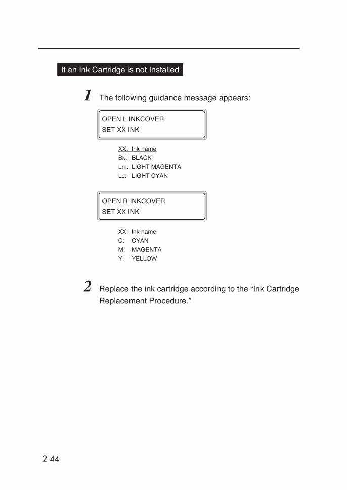
2-44
If an Ink Cartridge is not Installed
1 The following guidance message appears:
2 Replace the ink cartridge according to the “Ink Cartridge
Replacement Procedure.”
OPEN R INKCOVER
SET XX INK
XX: Ink name
C: CYAN
M: MAGENTA
Y: YELLOW
OPEN L INKCOVER
SET XX INK
XX: Ink name
Bk: BLACK
Lm: LIGHT MAGENTA
Lc: LIGHT CYAN

2-45
Sect
ion
2 B
asic
Ope
ratio
ns
Replacing Cartridges during Printing
The ink cartridges can be replaced during online printing without
interrupting the printing operation. Accordingly, guidance for ink
replacement during the online printing is displayed on the second
line of the LCD. The following describes how the guidance is shown
if the ink cover is opened during online printing or if the ink in the
main cartridge is used up:
<If the Ink Cover is Opened>
The guidance that prompts you to close the ink cover is displayed
on the second line of the LCD. The printing operation continues if
ink is present in the sub tank even though the ink cover is open.
However, no ink is supplied to the sub tank because the ink cover is
open.
If the ink in the sub tank is used up, the print pause mode is activated
and the printing operation is interrupted until the ink cover is closed.
To recover from the interrupted state, close the ink cover and press
the key. The pause mode is cancelled and printing will
restart.
PRINTING
ROLL: 104 / PAPER
PRINTING
INKCOVER IS OPEN
PRINTING
CLOSE X INKCOVER
XXXX:
L, R
Replacing Ink Cartridges

2-46
<If the Ink in Main Cartridge is Used Up>
The guidance that prompts you to replace the main cartridge is
displayed on the second line of the LCD. The printing operation
continues until the ink in the sub tank is used up. If replacement is
completed while ink remains in the sub tank, the printing operation
can continue without interruption.
If the main cartridge is not replaced even after the ink in the sub
tank is used up, the print pause mode is activated and the printing
operation is interrupted until the main cartridge is replaced.
To recover from the interrupted state, close the ink cover and press
the key. The pause mode is then cancelled and printing will
restart.
PRINTING
ROLL: 104 / PAPER
PRINTING
OPEN X INKCOVER
PRINTING
CHANGE YY INK
XXXX: L, R
YY: Bk Lm Lc Y M
C
- The guidance concerning the ink replacement during the
online printing is displayed on the second line of the LCD
in turn, as the guidance mentioned above.
The printer can restart by operation performed to restart
after an error.
HINT

2-47
Sect
ion
2 B
asic
Ope
ratio
ns
Replacing 4-Color Ink Cartridges
1 Prepare 4-color ink cartridge.Set the cartridges in position to the target ink holder.
2 Then, replace the ink cartridges following "Ink Cartridge
Replacement Procedure."
Black Yellow Magenta Cyan
NOTES- Exchange between 6-color ink cartridges and 4-color ink
cartridges should not be carried out more than 5 times.
- When exchanging the cartridges between 4 colors and 6
colors, replace all cartridges. If even one color of a 4-color
ink cartridge has been set, the printer operates in the 4-
color mode.
- If 6-color data are received in the 4-color mode (4-color
ink cartridges are set), the host posts an error to the printer
and printing is disabled.
- Cleaning is executed for all 6 colors even in the 4-color
mode. Accordingly, Lc and Lm not used for printing are
also consumed. Adjustment patterns are printed in 6 colors.
Replacing Ink Cartridges
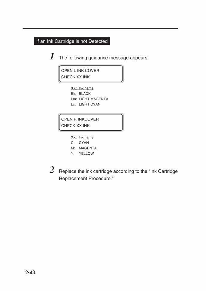
2-48
OPEN R INKCOVER
CHECK XX INK
XX: Ink name
C: CYAN
M: MAGENTA
Y: YELLOW
OPEN L INK COVER
CHECK XX INK
XX: Ink name
Bk: BLACK
Lm: LIGHT MAGENTA
Lc: LIGHT CYAN
If an Ink Cartridge is not Detected
1 The following guidance message appears:
2 Replace the ink cartridge according to the “Ink Cartridge
Replacement Procedure.”

2-49
Sect
ion
2 B
asic
Ope
ratio
ns
Waste ink bottle
Lever
KnobTube
NOTE
Replacing the Waste Ink BottleThis section describes how to replace a waste ink bottle.
A waste ink bottle should be replaced in the following two cases:
- If the waste ink bottle is full
- If a waste ink bottle is not installed
The waste ink bottle replacement procedures for these cases are
explained below.
- Do not replace the waste ink bottle during printing.
Waste Ink Bottle Replacement Procedure
1 Loosen the knob and lift up the lever from the waste ink
bottle.
2 Wait for a while to drop the remaining ink into the ink tube.
3 Take out the filled waste ink bottle from the printer, and
securely cap the waste ink bottle.
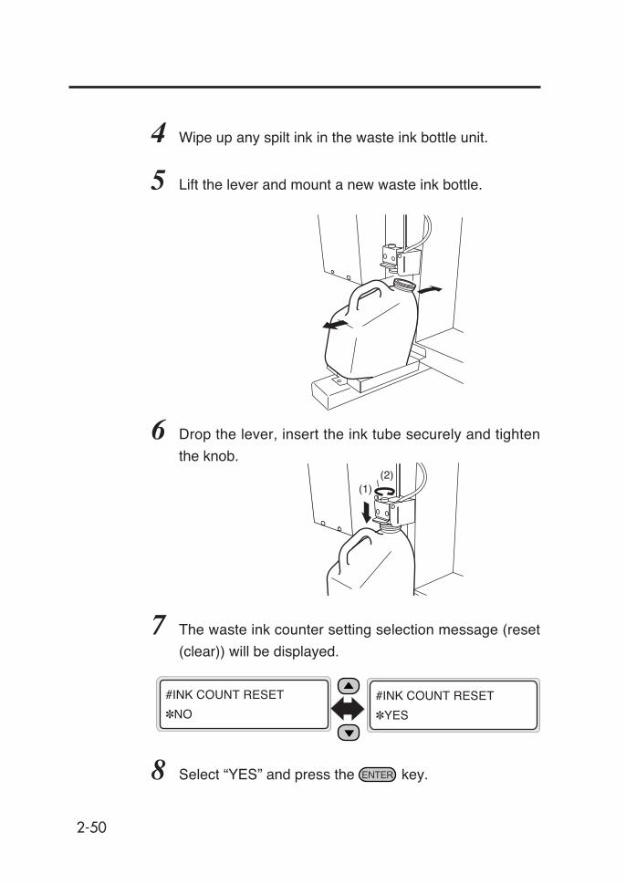
2-50
4 Wipe up any spilt ink in the waste ink bottle unit.
5 Lift the lever and mount a new waste ink bottle.
6 Drop the lever, insert the ink tube securely and tighten
the knob.
7 The waste ink counter setting selection message (reset
(clear)) will be displayed.
8 Select “YES” and press the key.
#INK COUNT RESET
✽NO
#INK COUNT RESET
✽YES
(1)(2)

2-51
Sect
ion
2 B
asic
Ope
ratio
ns
2 The waste ink counter setting selection message (reset
(clear)) will be displayed.
- The waste ink count is the amount of used ink (waste ink)
counted by the printer. When the count exceeds a certain
amount, an error is output prompting waste ink disposal.
It is a pseudo detection of waste ink full, not an actual
detection. Counting starts when the printer recognizes that
an empty waste ink bottle is set. Therefore, each time the
waste ink bottle is removed and mounted, *YES should be
selected to reset the waste ink counter. If this relationship
is not maintained, not only will the waste ink bottle full
detection counter malfunction, but also the waste ink bottle
could be full before a warning is output and the excessive
ink could spill out of the bottle.
3 Select “✽YES” and press the key.
#INK COUNT RESET
✽NO
#INK COUNT RESET
✽YES
NOTE
If the Waste Ink Bottle is Full
1 Replace the waste ink bottle according to the “Waste Ink
Bottle Replacement Procedure.”
- Check visually whether or not the waste ink bottle is full
before using the printer.
- If it is ful, replace it according to “Waste Ink Bottle
Replacement Procedure.”
NOTE
Replacing the Waste Ink Bottle
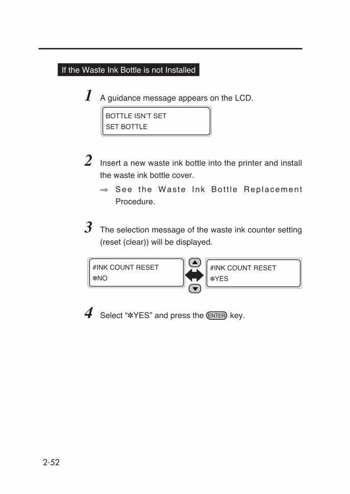
2-52
If the Waste Ink Bottle is not Installed
1 A guidance message appears on the LCD.
2 Insert a new waste ink bottle into the printer and install
the waste ink bottle cover.
⇒ See the Was te Ink Bo t t l e Rep lacement
Procedure.
3 The selection message of the waste ink counter setting
(reset (clear)) will be displayed.
4 Select “✽YES” and press the key.
BOTTLE ISN’T SET
SET BOTTLE
#INK COUNT RESET
✽NO
#INK COUNT RESET
✽YES

2-53
Sect
ion
2 B
asic
Ope
ratio
ns
Tension Bar Length AdjustmentUse the same tension bars on the feed side and the take-up side.
Insert the exclusive flange and fixing ring before attaching the
tension bar on the take-up side.
One set of tension bars includes 2 S size (16 inch, about 40.6cm)
bars, 1 M size (24 inch, about 60.7cm) bar and 1 L size (48 inch,
about 123.3cm) bar; and 4 flanges.
Jointing method (feed side)The bars connect by being screwed in to one another. If all 4 are
connected, the total length is 104 inches. The L size bar has male
joints on both ends, and must always be used. The M and S size
bars have female joints at one end for jointing to the L size bar.
Both ends of the jointed tension bar should be male to attach the
flanges.
L size (48 inch): 1 bar
M size (24 inch): 1 bar
S size (16 inch): 2 bars
Flanges: 4
Flanges for use with tension bar guide: 2
Fixing rings: 2

2-54
Jointing method (take-up side)Set the flanges and fixing rings for exclusive use on the take-up
side as shown in the figure. After setting them, joint the bars as on
the supply side.
Both ends of the jointed tension bar should be male to attach the
flanges.
-When inserting the tension bar into the
flange, match the positions of the
depression in the inner circumference
in the flange and the tension bar thread.
-When setting the fixing ring, clean the fixing ring and the
tension bar (for example by wiping with alcohol). If dirt
remains, the flange can become displaced during wind-up,
causing the wound-up media to be displaced.
CAUTION
desuseziS htgnelrabnoisneT htdiwaidemgnihctaM
L hcni84 hcni84othcni63
S,L hcni46 hcni46othcni94
S,S,L hcni08 hcni08othcni37
S,S,M,L hcni401 hcni401othcni98
Examples of tension bar combination
Fixing ringsFlange for take-up
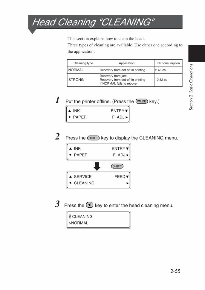
2-55
Sect
ion
2 B
asic
Ope
ratio
ns
Head Cleaning "CLEANING"This section explains how to clean the head.
Three types of cleaning are available. Use either one according to
the application.
1 Put the printer offline. (Press the key.)
2 Press the key to display the CLEANING menu.
3 Press the key to enter the head cleaning menu.
INK ENTRY
PAPER F. ADJ
SERVICE FEED
CLEANING
INK ENTRY
PAPER F. ADJ
# CLEANING
>NORMAL
Cleaning type Application Ink consumption
NORMAL Recovery from dot-off in printing 2.45 cc
STRONGRecovery from jamRecovery from dot-off in printingif NORMAL fails to recover
10.82 cc
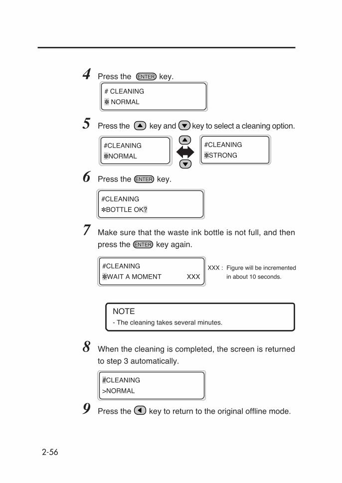
2-56
4 Press the key.
5 Press the key and key to select a cleaning option.
6 Press the key.
7 Make sure that the waste ink bottle is not full, and then
press the key again.
NOTE- The cleaning takes several minutes.
8 When the cleaning is completed, the screen is returned
to step 3 automatically.
9 Press the key to return to the original offline mode.
#CLEANING
✽WAIT A MOMENT XXXXXX : Figure will be incremented
in about 10 seconds.
# CLEANING
✽ NORMAL
#CLEANING
✽BOTTLE OK?
#CLEANING
>NORMAL
#CLEANING
✽STRONG
#CLEANING
✽NORMAL
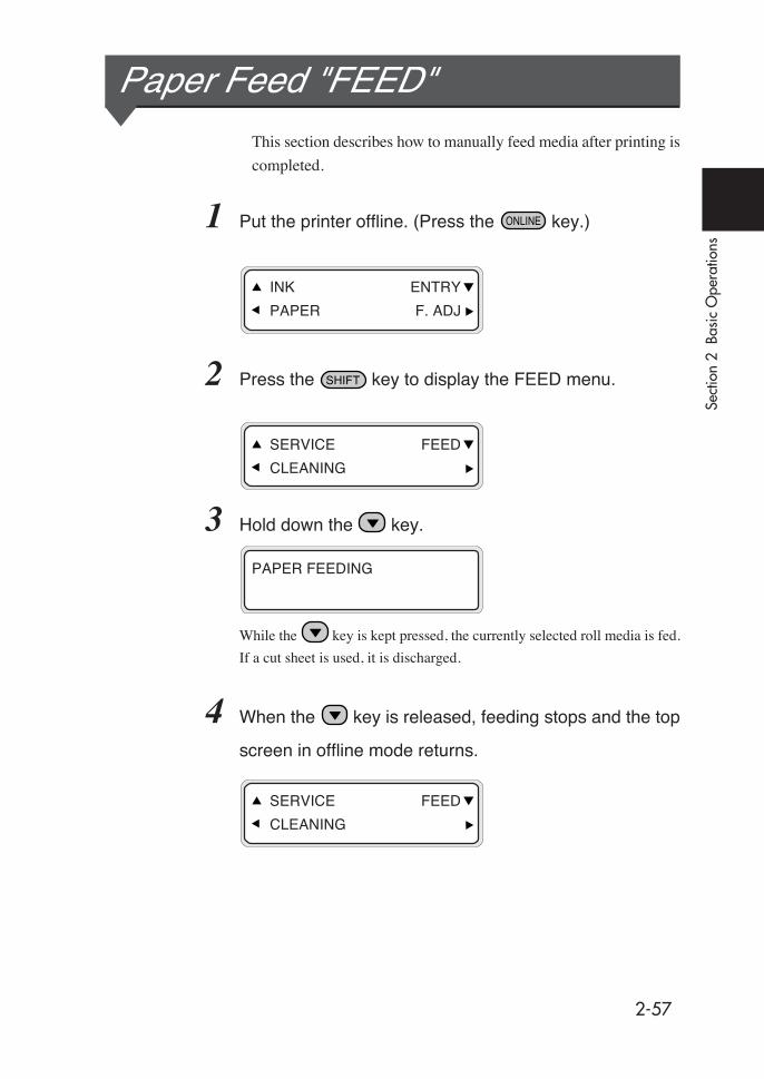
2-57
Sect
ion
2 B
asic
Ope
ratio
ns
Paper Feed "FEED"This section describes how to manually feed media after printing is
completed.
1 Put the printer offline. (Press the key.)
2 Press the key to display the FEED menu.
3 Hold down the key.
While the key is kept pressed, the currently selected roll media is fed.
If a cut sheet is used, it is discharged.
4 When the key is released, feeding stops and the top
screen in offline mode returns.
PAPER FEEDING
SERVICE FEED
CLEANING
SERVICE FEED
CLEANING
INK ENTRY
PAPER F. ADJ

2-58
Using the Origin Point Setting Function
<Origin Point Setting>
When a small size image such as an A4 size image is printed on
64-inch width media, a large blank will be generated as the figure
shows below.
In this case, rewind the print media and newly set the print origin
point to print an image on the blank area.
The print origin point setting at media rewinding is called the “Origin
Point Setting Function.”(1st time printing) (Media rewinding) (2nd time printing)
<How to Use the Origin Point Setting Function>
1 Lift the pressure roller up/down lever and rewind the
media.
- Rewind the media after the media is thoroughly dried.
If drying is not sufficient, the previously printed image may
be damaged.
SET PAPER
PUSH DOWN LEVER
NOTE
Pressure roller up/down lever
Origin point
Base point
Blank area

2-59
Sect
ion
2 B
asic
Ope
ratio
ns
2 Push the pressure roller up/down lever down.
3 Select the media position.
From the parameters, select "MAIN" or
"SUB" with the or key.
4 Select "USED" in the BASE FUNCTION menu and press
the key.
5 Input the Media width and press the key.
Pressure roller up/down lever
The previously detected media
width time is displayed as the
initial value.
BASE FUNCTION
SELECT: NOT USED
PAPER WIDTH
✽2642 mm
MEDIA POSITION
SELECT: MAIN
- The base function selection menu may not be displayed,
depending on the firmware version. To use the base
function, select "SELECT: MAIN B" for the media selection.
NOTE
Using the Origin Point Setting Function
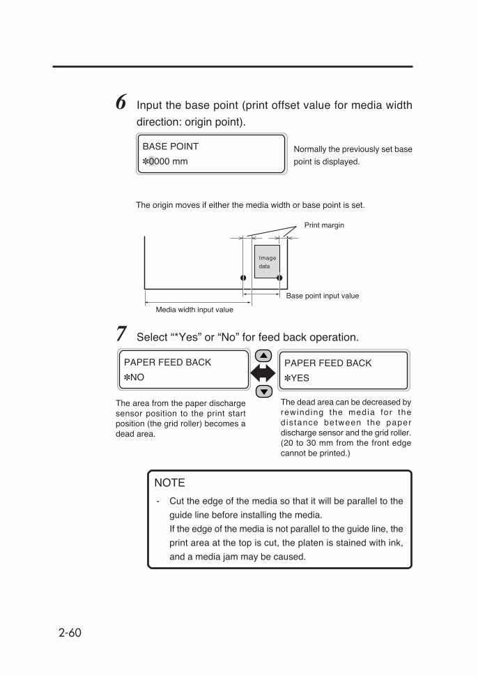
2-60
The area from the paper dischargesensor position to the print startposition (the grid roller) becomes adead area.
The dead area can be decreased byrewinding the media for thedis tance between the paperdischarge sensor and the grid roller.(20 to 30 mm from the front edgecannot be printed.)
NOTE
- Cut the edge of the media so that it will be parallel to the
guide line before installing the media.
If the edge of the media is not parallel to the guide line, the
print area at the top is cut, the platen is stained with ink,
and a media jam may be caused.
6 Input the base point (print offset value for media width
direction: origin point).
7 Select “*Yes” or “No” for feed back operation.
BASE POINT
✽0000 mm
The origin moves if either the media width or base point is set.
Print margin
Base point input value
Media width input value
PAPER FEED BACK
✽NO
PAPER FEED BACK
✽YES
Normally the previously set base
point is displayed.
Image
data

2-61
Sect
ion
2 B
asic
Ope
ratio
ns
8 Select a media type again.
9 Press the feed switch to slacken the media, and install
the tension bar in a slack part.
- The media width and base point settings cannot be saved.
- The origin point setting function can be used only for a
paper roll. It is not available for cut sheet.
Press the key to set the
media.
SELECT PAPER TYPE
PAPER: TYPE01
CHECK BUFFER
✽OK?
PREPARING PAPER
WAIT A MOMENT
NOTES
Using the Origin Point Setting Function
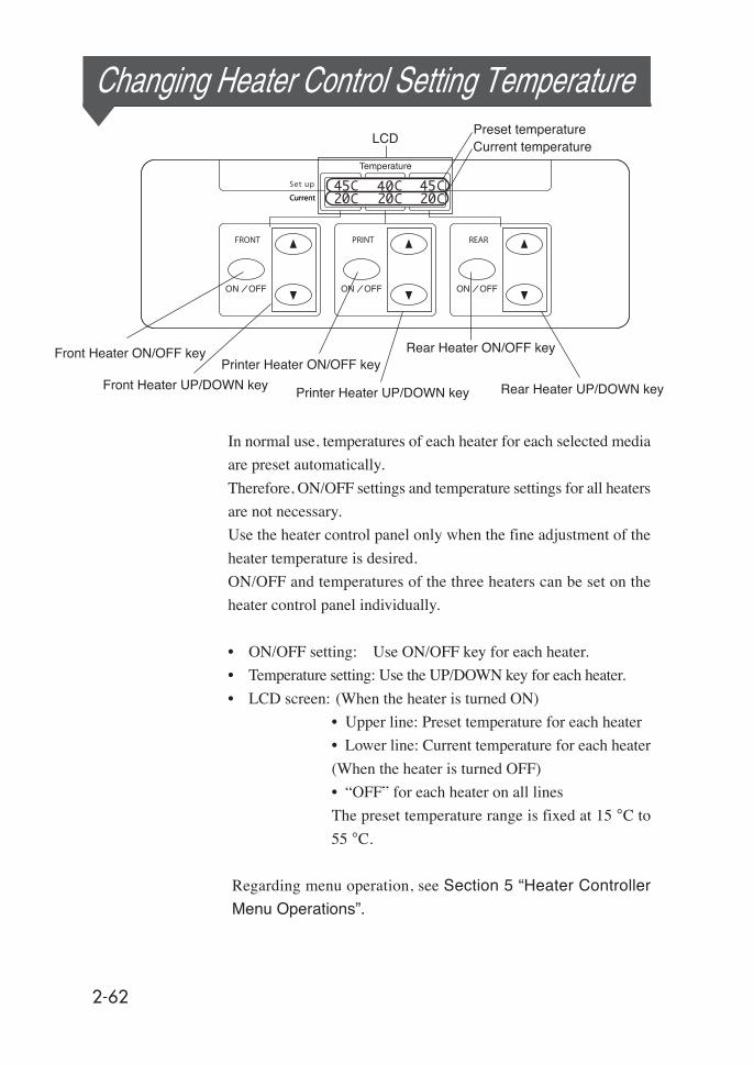
2-62
LCD
Printer Heater ON/OFF key
Printer Heater UP/DOWN key
Front Heater ON/OFF key
Front Heater UP/DOWN key
Rear Heater ON/OFF key
Rear Heater UP/DOWN key
Preset temperatureCurrent temperature
Changing Heater Control Setting Temperature
In normal use, temperatures of each heater for each selected media
are preset automatically.
Therefore, ON/OFF settings and temperature settings for all heaters
are not necessary.
Use the heater control panel only when the fine adjustment of the
heater temperature is desired.
ON/OFF and temperatures of the three heaters can be set on the
heater control panel individually.
• ON/OFF setting: Use ON/OFF key for each heater.
• Temperature setting: Use the UP/DOWN key for each heater.
• LCD screen: (When the heater is turned ON)
• Upper line: Preset temperature for each heater
• Lower line: Current temperature for each heater
(When the heater is turned OFF)
• “OFF” for each heater on all lines
The preset temperature range is fixed at 15 °C to
55 °C.
Regarding menu operation, see Section 5 “Heater Controller
Menu Operations”.

2-63
Sect
ion
2 B
asic
Ope
ratio
ns
Heater preset temperature by media
Recommended heater temperature and print mode set values (initial
values) by media are listed in the table below. Preset the heater
temperature according to the media you use.
It is recommended that the front heater, the printer heater and the
rear heater be set to 50 °C, 45 °C and 50 °C or lower, respectively.
When the print heater is set to higher than 45 °C, we recommend
setting the head action mode to "HIGHLIGHT PRIORITY."
NOTES- When the printer heater temperature is set to high, fixing
of the ink is improved, but media wrinkle or matte media
surface may be caused.
Adjust heater temperature according to the media type and
ambient temperature.
- When the print heater temperature is set to high, the printer
may print at low speed to ensure stable print quality .
- Set the front/rear heater temperatures 5 °C higher than
the print heater’s.
Bad temperature balance between the front/rear heater
and print heater may cause media wrinkle.
Media Type
Recommended presettemperature Print mode
FRONT PRINT REAR
Glossy vinylchloride
Glossy 45° C 40° C 45° CNormal 4-pass
bi-direction
Matte vinylchloride
Matte 45° C 40° C 45° CNormal 4-pass
bi-direction
Banner Banner 45° C 40° C 45° CNormal 4-pass
bi-direction
Changing Heater Control Setting Temperature

2-64
Flow of heater temperature setting
(1) If the media type is selected when setting the media, the initial temperature
of each heater for that media is set on the heater control panel.
- If the initial temperature has been set, the heater turns on. (Heating does
not start yet.)
- If the initial temperature is set to **, the heater turns off. (The set
temperature display on the heater control panel becomes OFF.)
(2) If print data are sent from the host (PC), either of the following operations
is performed before printing starts:
A) If "Priority Setting (Heater)" set for the media is "Data Priority"
- The temperature set with RIP (print data, job) overwrites the set
temperature on the heater control panel, and the heating starts. (The
heating does not start if the temperature set value is OFF.)
- If the temperature is not set with RIP (print data, job), the heating starts
at the temperature set on the heater control panel.
B) If "Priority Setting (Heater)" set for the media is "Panel Priority"
- The temperature set with RIP is ignored and the heating starts with the
temperature set on the heater control panel.
(3) Printing starts when the current temperatures of the front, printer, and rear
heaters all reach values exceeding "set temperature -2 °C".
If the current temperature is higher than the set temperature, printing starts
without waiting for the temperature to drop. Even after printing starts,
temperature control is applied so that the heaters maintain the set temperature.
(4) After that the temperature can be varied during printing by changing the
set temperature with the "TEMPERATURE UP/DOWN" key on the
heater control panel.
After printing is finished, the temperature changed in this section remains
the "set temperature".
(5) After that the print job returns to step (2).
For the initial temperature settings of front, printer, and rear heaters, and the
priority setting (heater), see Section 3 Entry Menu.
- The heaters operate under the condition displayed on the
heater control panel, whatever means are used to set
the temperature.HINT
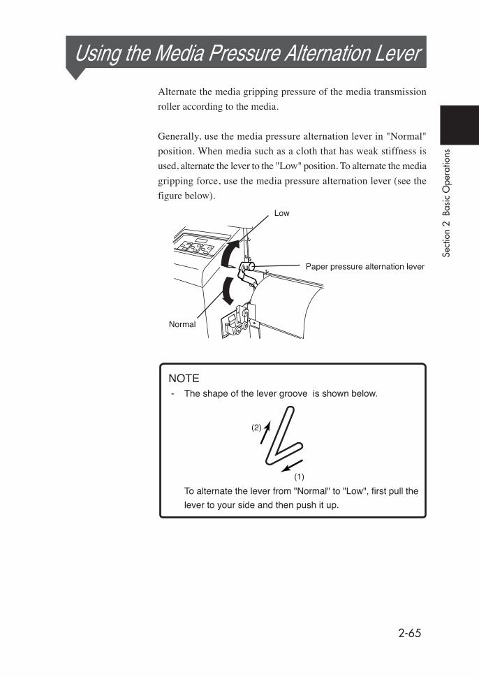
2-65
Sect
ion
2 B
asic
Ope
ratio
ns
Using the Media Pressure Alternation Lever
Alternate the media gripping pressure of the media transmission
roller according to the media.
Generally, use the media pressure alternation lever in "Normal"
position. When media such as a cloth that has weak stiffness is
used, alternate the lever to the "Low" position. To alternate the media
gripping force, use the media pressure alternation lever (see the
figure below).
Low
Normal
NOTE- The shape of the lever groove is shown below.
To alternate the lever from "Normal" to "Low", first pull the
lever to your side and then push it up.
(1)
(2)
Paper pressure alternation lever

2-66
Using the Head Up/Down LeverAlternate the head height according to the media you use.Use the head up/down lever to alternate the head height.(See the figure below)
2 Open the cap cover and loosen the 2 head fixing screws
with a screwdriver.
3 Alternate the head height with the head up/down lever.
Generally, preset the head down for glossy vinyl chloride and matte vinyl
chloride, and preset the head up for banner and FF.
When the media thickness is 0.5 mm or more, preset the head up regardless
of media type.
If slip sheets are used for mesh tarpaulin or during media feed, or if thin
media are used, the head is rubbed with the media due to the media floating.
Preset the head in the up position in this case.
Head fixing screw
Head up/down lever
Cap cover
Up (for thinner media (standard))
Down (for thicker media)
1 Select the SERVICE menu and execute HEAD HEIGHT
ADJ on the operation panel.
#ADJUST HEIGHT
>The alarm buzzer will sound.

2-67
Sect
ion
2 B
asic
Ope
ratio
ns
4 Tighten the 2 head fixing screws (2 pieces).
- When changing the head height, tighten the head fixing
screws while pushing the head down softly with your hand.
- When the head height is changed, change head height
setting (16) in the ENTRY menu (Section 3).
- When the head height is changed, displacement of the
printing may occur during bi-directional printing. In that
case, adjust the correction value for reciprocating printing.
(See (17) Reciprocating print position (Left) adjustment,
and (18) Reciprocating print position (Right) adjustment
in ENTRY menu.)
5 Close the rear cover and the cap cover.
The alarm buzzer stops.
NOTES
Using the Head Up/Down Lever
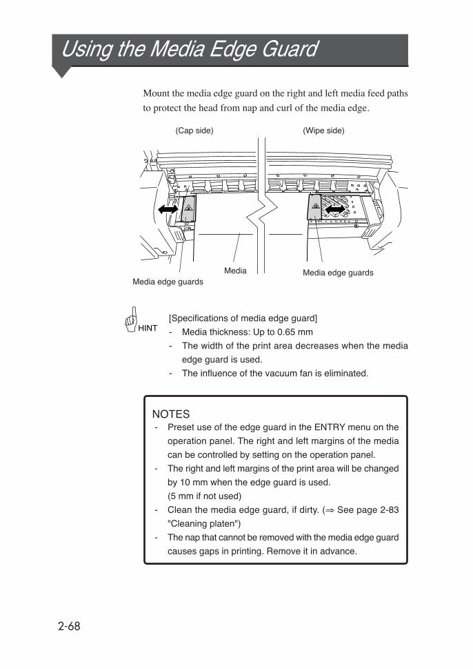
2-68
- Preset use of the edge guard in the ENTRY menu on the
operation panel. The right and left margins of the media
can be controlled by setting on the operation panel.
- The right and left margins of the print area will be changed
by 10 mm when the edge guard is used.
(5 mm if not used)
- Clean the media edge guard, if dirty. (⇒ See page 2-83
"Cleaning platen")
- The nap that cannot be removed with the media edge guard
causes gaps in printing. Remove it in advance.
NOTES
Mount the media edge guard on the right and left media feed paths
to protect the head from nap and curl of the media edge.
Using the Media Edge Guard
Media edge guardsMediaMedia edge guards
(Cap side) (Wipe side)
[Specifications of media edge guard]
- Media thickness: Up to 0.65 mm
- The width of the print area decreases when the media
edge guard is used.
- The influence of the vacuum fan is eliminated.
HINT

2-69
Sect
ion
2 B
asic
Ope
ratio
ns
Using the Print Pause/Restart and Cancel Keys
Print pause/ restart and cancel are also available from the rear
(discharge) side of the printer.
This arrangement permits print pause/re-start and print cancel to
be done while checking the print condition from the paper discharge
side.
Operations of the ONLINE and CANCEL keys are the same as
those of the operation panel’s.
<Special use of Print Pause/Restart and Cancel key>
- If the Cancel key is pressed continuously for one second
with the LED in ON state, the media can be fed.
Media
(Rear)
ONLINE key:
Pause/Restart printing
Cancels printing
CANCEL key:
HINT

2-70
Inspection & MaintenanceRegular inspection and maintenance are described below.
Regular Inspection and Maintenance Guide
The printer needs regular inspection and maintenance.
The table below lists all regular inspection and maintenance.
For details of each item, see the page referred to.
Refer to Section 3 for details of operation.
Category Inspection/Maintenance Refer to
1 Daily inspection and maintenance
- Wiper Blade Cleaning- Wiper Sponge Cleaning- Capping Unit Cleaning- Waste Ink Bottle Disposal- Carriage Cleaning- Normal Head Cleaning- Test Printing
2-712-732-742-752-752-762-76
2Monthly inspection andmaintenance
- Head cleaning 2-77
3When leaving the printer for a longtime in the power OFF state (2weeks or more)
- Service Cleaning 2-77
4When restarting the printer after along absence (2 weeks or more)
- Head Washing- Ink charging after head washing
2-78
5When restarting the printer after along absence (within 2 weeks) withthe printer in the power OFF state.
- Head Washing- Ink charging after head washing
2-802-81
6When leaving the printer withpower OFF for one month or more.
A service call error message willbe displayed on the operationpanel. Contact our service center.
2-81
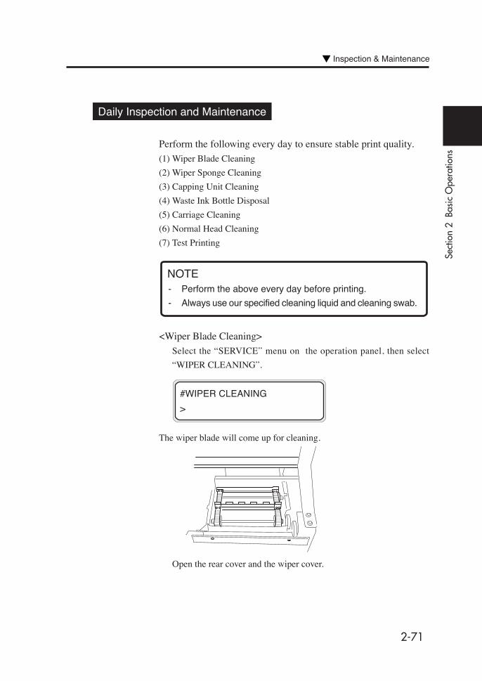
2-71
Sect
ion
2 B
asic
Ope
ratio
ns
Daily Inspection and Maintenance
Perform the following every day to ensure stable print quality.
(1) Wiper Blade Cleaning
(2) Wiper Sponge Cleaning
(3) Capping Unit Cleaning
(4) Waste Ink Bottle Disposal
(5) Carriage Cleaning
(6) Normal Head Cleaning
(7) Test Printing
NOTE
<Wiper Blade Cleaning>
Select the “SERVICE” menu on the operation panel, then select
“WIPER CLEANING”.
The wiper blade will come up for cleaning.
Open the rear cover and the wiper cover.
#WIPER CLEANING
>
- Perform the above every day before printing.
- Always use our specified cleaning liquid and cleaning swab.
Inspection & Maintenance

2-72
Check that there are no dregs of dried ink on and no damage to the
blades.
Clean the front and back of the blades with a cleaning swab soaked in
wiper cleaning liquid.
After completion of the cleaning, close the wiper cover and the rear
cover to return the wiper to its original position.
- Take extreme care not to allow the wiper cleaning liquid to
contact to parts other than wiper blades.
Contact of wiper cleaning liquid with belts or sensors may
cause malfunction.
Wiper blades
NOTE
Rear cover
Wiper cover
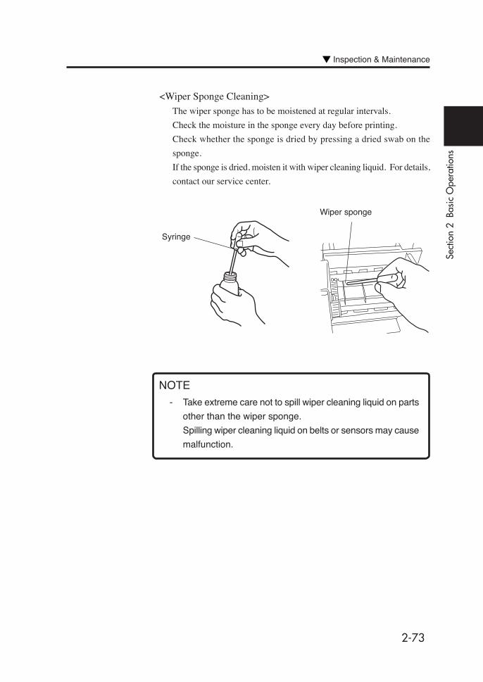
2-73
Sect
ion
2 B
asic
Ope
ratio
ns
NOTE
- Take extreme care not to spill wiper cleaning liquid on parts
other than the wiper sponge.
Spilling wiper cleaning liquid on belts or sensors may cause
malfunction.
<Wiper Sponge Cleaning>
The wiper sponge has to be moistened at regular intervals.
Check the moisture in the sponge every day before printing.
Check whether the sponge is dried by pressing a dried swab on the
sponge.
If the sponge is dried, moisten it with wiper cleaning liquid. For details,
contact our service center.
Wiper sponge
Syringe
Inspection & Maintenance

2-74
#CAP CLEANING
>
NOTE
<Capping Unit Cleaning>
Select the SERVICE menu on the operation panel, then select CAP
CLEANING”.
The head carriage will move to the wipe side and you can easily access
the capping unit.
(The buzzer stops.)
Open the rear cover and cap cover. Wipe the edge and periphery of the
upper surface of all (six) caps carefully with the cleaning swab.
Close the cap cover and rear cover. The head carriage will return to the
capping unit position (home position) automatically.
(The buzzer stops)
- Do not leave the printer for a long time with the head
carriage not on the capping unit.
Clean the edge and periphery
of the upper surface of the
cap.

2-75
Sect
ion
2 B
asic
Ope
ratio
ns
<Waste Ink Bottle Disposal>
If the waste ink bottle is full, pour the waste ink into the proper container
you prepared to empty the waste ink bottle.
<Carriage Cleaning>
Clean the carriage brush.
Clean the shield HB frequently to which the dust stained with ink will
attach. This dust soils the surface of printed matter.
Also, clean the platen surface.
Inspection & Maintenance
Brush
Shield HB

2-76
<Normal Head Cleaning>
Enter the “CLEANING” menu and select “NORMAL” on the operation
panel.
<Test Printing>
Enter the “ADJUST” menu and select “TEST PRINT” on the operation
panel.
Check no print dot-off and missing.
Perform test printing as the 1st print on every day and especially after
cap cleaning for head cleaning.
When print dot-off occurs on a test print, perform normal head cleaning
again.
- Do not leave the print head at a position other than on the
capping unit for a long time. Finish the work within 5 minutes
and cap the print head.
Perform normal head cleaning after completion of the test
print.
NOTE
2-77
Sect
ion
2 B
asic
Ope
ratio
ns
Monthly Inspection and Maintenance
<Head Cleaning>
Clean the head once per month according to the documentation attached
to the head cleaner kit.
When Leaving the Printer for a Long Time (2 weeks or more) in Power OFF State
Store the printer after cleaning the head and ink path with the
maintenance liquid, and charge the maintenance liquid.
Six maintenance liquid cartridges and six dummy cartridges are
necessary.
Prepare the storage kit (IP6-137).
Six maintenance liquid cartridges (IP6-107) and six dummy
cartridges (IP6-118) are packed together in the storage kit.
Six maintenance liquid cartridges are used up by one service clean.
<Service Cleaning>
Select the “SERVICE” menu on the operation panel, then select “
SERVICE CLEAN.”
After service cleaning is finished, turn the power OFF with dummy
cartridges inserted and leave the printer as it is.
Head washing is mandatory when restoring the printer from the status
in which service cleaning is performed.
#SERVICE
>SERVICE CLEAN
Inspection & Maintenance
2-78
When Restarting the Printer After a Long Absence (2 weeks or more)
Clean the head and ink path with cleaning liquid.
Six cleaning liquid cartridges and six dummy cartridges are
necessary.
Prepare the cleaning kit (IP6-117).
Six cleaning liquid cartridges (IP6-119) and six dummy cartridges
(IP6-118) are packed together in the cleaning kit.
Six cleaning liquid cartridges are used up by one head wash.
<Head Wash>
Select HEAD WASH in the SERVICE menu on the operation panel.
After performing a head wash, charge the ink (See Ink Charge after
Head Washing).
- The printer performs fill cap operation to maintain good
head condition after the first 20 hours on standby and every
3 days thereafter.
It is recommended to keep the printer ON except when the
printer is not used for a long time.
Avoid leaving the printer with no ink for one month or more
for head protection.
- Do not open and close the rear cover and do not lift and
push down the levers during service cleaning and head
washing.
Doing so can cause the printer to start service cleaning
and head washing from the beginning.
CAUTION
#SERVICE
>HEAD WASH

2-79
Sect
ion
2 B
asic
Ope
ratio
ns
Insert the ink cassettes and fill the ink.
Leave the printer for at least one hour after completion of ink filling.
Check moisture in the wiper sponge.
Perform test printing.
If characters are shipped during test printing, perform normal cleaning
in the “CLEANING” menu.
#SERVICE
>INK CHARGE
NOTE
- About 300cc of ink is used for the ink filling. If a cartridge in
which the remaining amount of ink is less than 300cc has
been inserted, replace it with a cartridge that contains at
least 300cc.
Inspection & Maintenance
<Ink Filling After Head Washing>
Fill the ink after head washing before printing after the printer has not
been used for a long time.
Select the “SERVICE” menu on the operation panel, then select “INK
CHARGE”.

2-80
- The printer performs fill cap operation to maintain goodhead condition after the first 20 hours in the print wait stateand every 3 days thereafter.It is recommended to keep the printer ON except when theprinter is not used for a long time.Avoid leaving the printer with no ink for one month or morefor head protection.
- Do not open and close the rear cover and do not lift andpush down the levers during service cleaning and headwashing.If this is done, the printer may start service cleaning andhead washing from the beginning.
NOTE
When Restarting the Printer After a Long Absence (within 2 weeks) in Power OFF State
<Head Washing>
Cleaning the head and ink path with cleaning liquid.
Six cleaning liquid cartridges and six dummy cartridges are mandatory.
Prepare the cleaning kit (IP6-117).Six cleaning liquid cartridges (IP6-119) and six dummy cartridges
(IP6-118) are packed together in the cleaning kit.
Six cleaning liquid cartridges are used up by one head wash.
After performing the head wash, fill the ink.
#SERVICE
>HEAD WASH

2-81
Sect
ion
2 B
asic
Ope
ratio
ns
- For head protection do not leave the printer unfilled withmaintenance liquid more than 2 weeks in the power OFFstate.
- When leaving the printer for one month or more, consultwith your dealer or our nearest service center in advance.
When Leaving the Printer with Power OFF for One Month or More
Regardless of whether service cleaning is performed, a service callerror message will be displayed on the operation panel.Contact an SIIT service center.
CAUTION
NOTE
- About 300cc of ink is used for the ink filling. If a cartridge in
which the remaining amount of ink is less than 300cc has
been inserted, replace it with a cartridge that contains more
than 300cc of ink.
Inspection & Maintenance
<Ink Filling After Head Washing>
Charge the ink after head washing before printing when the printer is
left idle for a long time.
Enter the “SERVICE” menu and select “INK CHARGE” on the
operation panel.
Insert the ink cassettes and fill the ink.
Leave the printer for at least one hour after completion of ink filling.
Check moisture in the wiper sponge.
Perform test printing.
If characters are shipped during the test printing, perform normal
cleaning in the “CLEANING” menu.
(See page 2-55.)
#SERVICE
>INK CHARGE

2-82
Cleaning
Cleaning housing
If the housing of the printer becomes stained, wipe up the stain with asoft cloth soaked in water or water dissolved neutral detergent andwringed well.
- Before cleaning, turn the AC1 and AC2 power switches OFF.- Do not use volatile solvent such as thinner or benzine to
prevent fading or deterioration of the coating.
Cleaning rear cover and rear paper guide
Vacuum with a vacuum cleaner.If stains are heavily accumulated, wipe them with a soft cloth soakedin cleaning liquid.
- Turn the printer and heater power switches OFF beforecleaning.
- Do not blow paper dust off.Doing so can cause print quality to deteriorate.
Rear paper guide
Rear cover
NOTES
NOTES
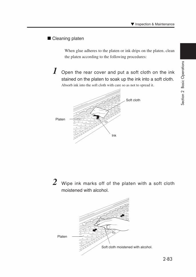
2-83
Sect
ion
2 B
asic
Ope
ratio
ns
Soft cloth moistened with alcohol.
Platen
Inspection & Maintenance
2 Wipe ink marks off of the platen with a soft cloth
moistened with alcohol.
Cleaning platen
When glue adheres to the platen or ink drips on the platen, clean
the platen according to the following procedures:
1 Open the rear cover and put a soft cloth on the ink
stained on the platen to soak up the ink into a soft cloth.Absorb ink into the soft cloth with care so as not to spread it.
Ink
Soft cloth
Platen

2-84
3 If ink gets into vacuum holes on the platen, wipe ink out of
the holes with a commercially-available mini-cotton
swab, then wipe out again with a mini-cotton swab
moistened with alcohol.
Use a ø3 mm mini-cotton swab.
Platen
Mini-cotton swab
3-1
Sect
ion
3 O
pera
tion
Pane
l Men
u O
pera
tions
Section 3 Operation PanelMenu Operations
This section outlines the user menu structure and operations.
LCD Messages and Printer State
Operation in Online State
Basic Menu Operation in Offline State
Menu Operations
Contents of This Section

3-2
LCD Messages and Printer StateThis section explains the display on the LCD and printer state.
Display on the LCD
(1) Initialization
The printer is being initialized.
Booting
*: When the system starts normally, the printer goes goes
online and enters idle mode automatically.
(2) Online state (idle mode)
The printer can receive data from the computer.
PRINT READY
MAIN : 104 / PAPER
Status display
Media information
INITIALIZING
WAIT A MOMENT

3-3
Sect
ion
3 O
pera
tion
Pane
l Men
u O
pera
tions
(3) Online state (print mode)
The printer is printing.
PRINTING
MAIN : 104 / PAPER
Status display
Media information
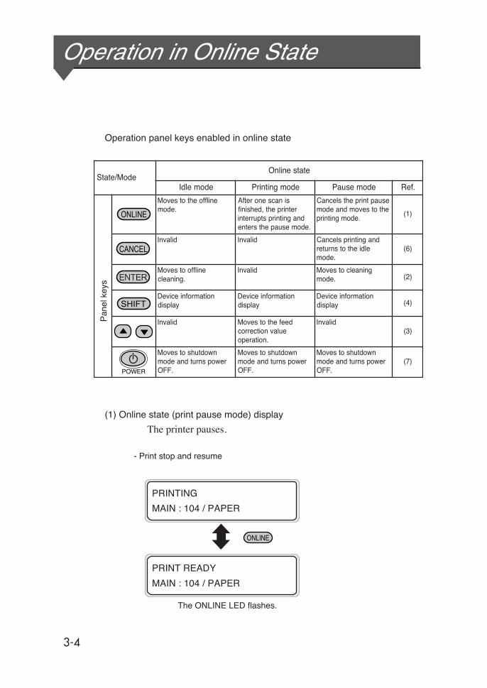
3-4
Operation in Online State
Operation panel keys enabled in online state
(1) Online state (print pause mode) display
The printer pauses.
- Print stop and resume
The ONLINE LED flashes.
PRINT READY
MAIN : 104 / PAPER
PRINTING
MAIN : 104 / PAPER
edoM/etatSetatsenilnO
edomeldI edomgnitnirP edomesuaP .feR
enilffoehtotsevoM.edom
sinacsenoretfAretnirpeht,dehsinif
dnagnitnirpstpurretni.edomesuapehtsretne
esuaptnirpehtslecnaCehtotsevomdnaedom
.edomgnitnirp)1(
dilavnI dilavnI dnagnitnirpslecnaCeldiehtotsnruter
.edom)6(
enilffootsevoM.gninaelc
dilavnI gninaelcotsevoM.edom )2(
noitamrofnieciveDyalpsid
noitamrofnieciveDyalpsid
noitamrofnieciveDyalpsid )4(
dilavnI deefehtotsevoMeulavnoitcerroc
.noitarepo
dilavnI)3(
nwodtuhsotsevoMrewopsnrutdnaedom
.FFO
nwodtuhsotsevoMrewopsnrutdnaedom
.FFO
nwodtuhsotsevoMrewopsnrutdnaedom
.FFO)7(
Pan
el k
eys
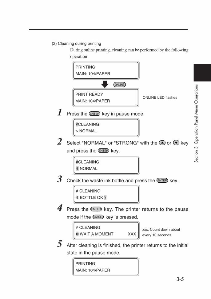
3-5
Sect
ion
3 O
pera
tion
Pane
l Men
u O
pera
tions
(2) Cleaning during printing
During online printing, cleaning can be performed by the following
operation.
1 Press the key in pause mode.
2 Select "NORMAL" or "STRONG" with the or key
and press the key.
3 Check the waste ink bottle and press the key.
4 Press the key. The printer returns to the pause
mode if the key is pressed.
5 After cleaning is finished, the printer returns to the initial
state in the pause mode.
xxx: Count down about
every 10 seconds.
ONLINE LED flashes
#CLEANING
> NORMAL
PRINTING
MAIN: 104/PAPER
#CLEANING
✽ NORMAL
# CLEANING
✽ BOTTLE OK ?
# CLEANING
✽ WAIT A MOMENT XXX
PRINTING
MAIN: 104/PAPER
PRINT READY
MAIN: 104/PAPER
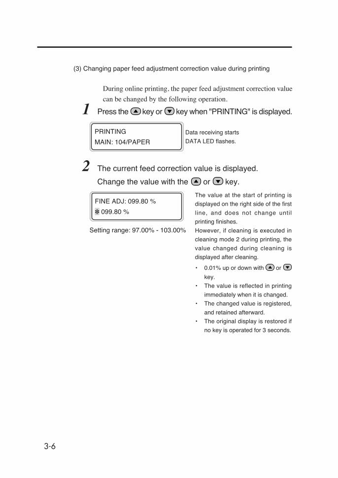
3-6
Setting range: 97.00% - 103.00%
The value at the start of printing is
displayed on the right side of the first
line, and does not change until
printing finishes.
However, if cleaning is executed in
cleaning mode 2 during printing, the
value changed during cleaning is
displayed after cleaning.
• 0.01% up or down with or
key.
• The value is reflected in printing
immediately when it is changed.
• The changed value is registered,
and retained afterward.
• The original display is restored if
no key is operated for 3 seconds.
(3) Changing paper feed adjustment correction value during printing
During online printing, the paper feed adjustment correction value
can be changed by the following operation.
1 Press the key or key when "PRINTING" is displayed.
2 The current feed correction value is displayed.
Change the value with the or key.
Data receiving starts
DATA LED flashes.
PRINTING
MAIN: 104/PAPER
FINE ADJ: 099.80 %
✽ 099.80 %
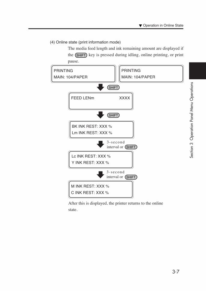
3-7
Sect
ion
3 O
pera
tion
Pane
l Men
u O
pera
tions
Operation in Online State
(4) Online state (print information mode)
The media feed length and ink remaining amount are displayed if
the key is pressed during idling, online printing, or print
pause.
BK INK REST: XXX %
Lm INK REST: XXX %
PRINTING
MAIN: 104/PAPER
Lc INK REST: XXX %
Y INK REST: XXX %
3-secondinterval or
After this is displayed, the printer returns to the online
state.
3 - secondinterval or
FEED LENm XXXX
PRINTING
MAIN: 104/PAPER
M INK REST: XXX %
C INK REST: XXX %

3-8
(6) Print cancel
To cancel the print, press the key in the online pause mode.
ONLINE LED flashing
(5) Skew check during printing
The printer checks for skew of media every 2 meters of print length.
If a skew exceeding the specified value is detected, the printer enters
the print pause mode and displays an inquiry as to whether printing
is to be continued or cancelled on the screen.
PRINTING
MAIN: 104/PAPER
If a skew is detected
ONLINE LED flashing (pause state)
(Execution of skew check)
key to cancel print key to continue print
PRINTING
MAIN: 104/PAPER
DETECT SKEW
CONTINUE/CANCEL
PRINTING
MAIN: 104/PAPER
PRINTING
MAIN: 104/PAPER
LIFT LEVER
SET PAPER

3-9
Sect
ion
3 O
pera
tion
Pane
l Men
u O
pera
tions
Operation in Online State
(7) Shutdown
Pressing the Power ON/OFF switch in idle mode, during online
printing or print pause causes the printer to execute shutdown.
The printer can be shut down in two ways:
1. Turning power OFF without fill cap operation
Press the power ON/OFF key together with the key,
and the power is turned OFF, skipping the fill cap operation.
Use this operation for temporary power OFF in such cases as
an error recovery or failure of communication with the host.
2. Turning power OFF with fill cap operation
Press the power ON/OFF key on the operation panel
continuously for 2 to 3 seconds. Power is turned OFF after the
fill cap operation is executed.
For further information, see "Section 2 Turning Power ON/OFF."
SHUTDOWN
WAIT A MOMENT

3-10
Basic Menu Operation in Offline StateWhen the key is pressed in the online idle mode, the printer
enters the offline mode, a menu group appears on the LCD, and
menu operations are enabled.
Menu Hierarchical Structure
The menu has the following hierarchical structure:
<Menu group>
This menu is displayed at the first level.
Some menus have several sub-menus.
<Second-level menus>
Sub-menus of the menu group
<Parameters>
Select a menu item or enter a value.
There are three methods to set parameters: choice, value entry, and
execution.
INK ENTRY
PAPER F.ADJ
SERVICE FEED
CLEANING
FUNC SYSTEM
ADJUST RESET

3-11
Sect
ion
3 O
pera
tion
Pane
l Men
u O
pera
tions
INK ENTRY PAPER F. ADJ
(1)
Menu Tree
(2) (3)
XX INK REST: YYY%DATE : XX/XX/XX
Execution form(Display)
SHEET(PAPER)YYYYmmXZZZZmm
Execution form(Display)
DUAL (PAPER)104
Execution form(Display)
FACE (PAPER)104
Execution form(Display)
BACK 1 (PAPER)104
Execution form(Display)
BACK 2 (PAPER)104
Execution form(Display)
#SELECT PAPER>01 : TYPE01
Enter a choice01 to 20
#NAME>01 : TYPE01
Enter characters
#FEED ADJUST>01 : 099.80%
Enter a value
97.0 to 103.0
#SCAN WAIT TIME>01 : 000sec
Enter a value
000 to 999
Enter a choice.- NORMAL - H-QUALITY- H-DENSITY - 3 TIMES- H-QUALITY 2- H-DENSITY 2- DRAFT - FAST- F-H-QUALITY- F-H-DENSITY- F-3 TIMES- F-H-QUAL 2- F-H-DENS 2- FINE DRAFT
#PRINT MODE>01 : NORMAL
MAIN (PAPER)104
Execution form(Display)
SUB (PAPER)104
Execution form(Display)
MAIN B (PAPER)104
Execution form(Display)
SUB B (PAPER)104
Execution form(Display)

3-12
(4)
(3)
#PAPER SET MODE>01 : NORMAL
Enter a choice- NORMAL- SAVING
Enter a choice- HIGH - MIDDLE- LOW - OFF
#VACUUM>01 : HIGH
#FRONT HEATER>01 : 30C
Enter a value
15 to 55, **
#PRINT HEATER>01 : 40C
Enter a value
15 to 55, **
#REAR HEATER>01 : 45C
Enter a value
15 to 55, **
#COLOR STRIPE>01 : ON
Enter a choice- ON- OFF
#HEAD MOTION>01 : NORMAL
Enter a choice- NORMAL- HIGHLIGHT
#HEAD HEIGHT>01 : NORMAL
Enter a choice- NORMAL- HIGH
#I-POS (L) ADJ 2 YY>01 : +00&A
Enter a value-32 to +31, a to HYY: Bk, Lm, Lc, Y, M, C
#I-POS (R) ADJ 2 YY>01 : +00&A
Enter a value-32 to +31, a to HYY: Bk, Lm, Lc, Y, M, C
#I-POS (L) ADJ YY>01 : +00&A
Enter a value-32 to +31, a to HYY: Bk, Lm, Lc, Y, M, C
#I-POS (R) ADJ YY>01 : +00&A
Enter a value-32 to +31, a to HYY: Bk, Lm, Lc, Y, M, C
#PAPER FEED MODE>01 : SEQUENCE 1
Enter a choice- SEQUENCE 1- SEQUENCE 2
#EDGE GUARD>01 : USE
Enter a choice- USE- NOT USE
#DIRECTION>01 : BI
Enter a choice.- BI- UNI

3-13
Sect
ion
3 O
pera
tion
Pane
l Men
u O
pera
tions
(4)(1) (2)
Basic Menu Operation in Offline State
Enter a choice- MODE 1 - MODE 2- MODE 3
# CLEANING MODE>01: MODE 1
# BACK ADJUST>01: +0000 PULSE
Enter a value
±2000
Enter a choice- DATA- PANEL
Enter a choice- DATA- PANEL
Enter a choice- DATA- PANELEnter a value- AUTO- MANUAL- MANUAL 2
Enter form961 to 2642
Enter a value01 to 99
Enter form961 to 2642
Enter a choice- OFF- ON
Enter a value0000 to 9999
Enter a choice- OFF- ON
Enter a value01 to 20
Enter a value01 to 20
Enter a value01 to 20
#PRIORITY FEED>01 : DATA
#PRIORITY MODE>01 : DATA
#PRIORITY HETER>01 : DATA
#DETECT WIDTH>01 : AUTO
#SIZE>01 : 2642mm
#SIZE2>01 : 2642mm
#PEEL MODE>01 : OFF
#INTERVAL>01 : 0000 SCAN
#WAIT TIME>01 : 10sec
#TEMPERATURE GAP>01 : OFF
#DELETE PAPER>02 : TYPE02 OK?
#COPY SOURCE>01
#COPY DEST>01→01✽

3-14
# FEED PATTERN>ROUGH (NORMAL)
#FEED ADJUST>099.80%
#CLEANING>NORMAL
#FEEDING
Enter a choice- ROUGH (NORMAL)- ROUGH (H-QUAL)- ROUGH (H-DENS)- ROUGH (3 TIMES)- ROUGH (H-QUAL 2)- ROUGH (H-DENS 2)- ROUGH (DRAFT)- DETAIL (NORMAL)- DETAIL (H-QUAL)- DETAIL (H-DENS)- DETAIL (3 TIMES)- DETAIL (H-QUAL 2)- DETAIL (H-DENS 2)- DETAIL (DRAFT)
Enter a value97.0 to 103.0%
Enter a choice- NORMAL- STRONG
SERVICE FEED
CLEANING
Execution form
# BACK PATTERN>NORMAL
# BACK ADJUST>+0000 PULSE
Enter a choice- NORMAL- H-DENSITY- H-QUALITY- H-QUALTY 2- H-DENSITY 2- 3 TIMES- DRAFT
Enter a value±2000
(1) (2)
#FILL CAP>
Execution form
# ADJUST HEIGHT>
Execution form
#WIPER CLEANING>
Execution form
#CAP CLEANING>
Execution form
#SERVICE>SERVICE CLEAN
Enter a choice- SERVICE CLEAN- HEAD WASH- INK CHARGE- INK EXTRACT
#WAIST INK SAVING>NORMAL
Enter a choice- NORMAL- SAVING
(5)
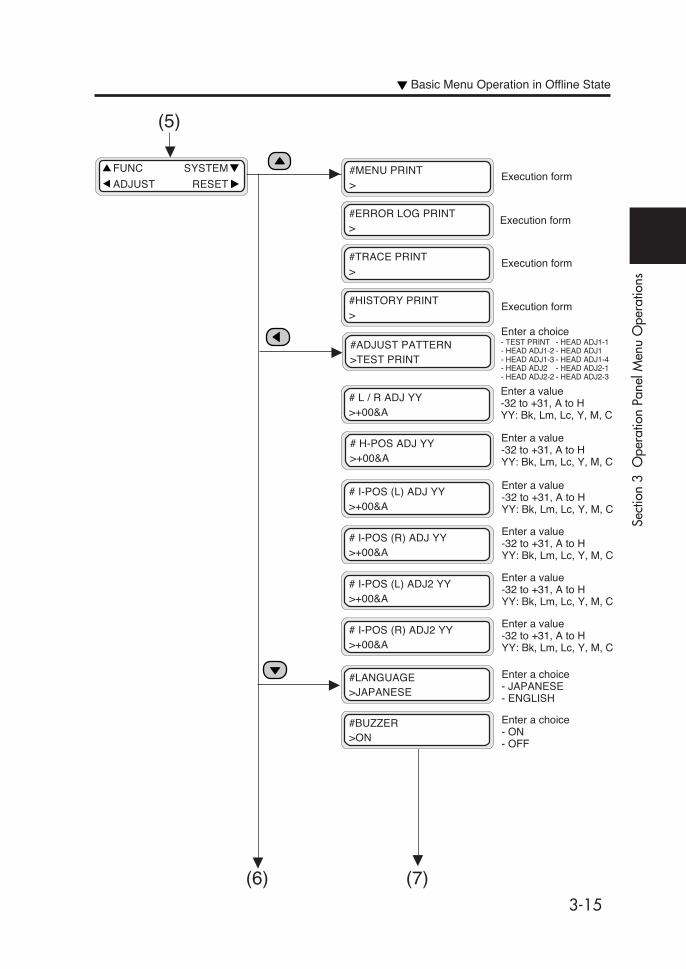
3-15
Sect
ion
3 O
pera
tion
Pane
l Men
u O
pera
tions
FUNC SYSTEM
ADJUST RESET
#ADJUST PATTERN>TEST PRINT
Enter a choice- TEST PRINT - HEAD ADJ1-1- HEAD ADJ1-2 - HEAD ADJ1- HEAD ADJ1-3 - HEAD ADJ1-4- HEAD ADJ2 - HEAD ADJ2-1- HEAD ADJ2-2 - HEAD ADJ2-3
(7)
(5)
#TRACE PRINT>
Execution form
#HISTORY PRINT>
Execution form
#ERROR LOG PRINT>
Execution form
#MENU PRINT>
Execution form
# L / R ADJ YY>+00&A
Enter a value-32 to +31, A to HYY: Bk, Lm, Lc, Y, M, C
# H-POS ADJ YY>+00&A
Enter a value-32 to +31, A to HYY: Bk, Lm, Lc, Y, M, C
# I-POS (L) ADJ YY>+00&A
Enter a value-32 to +31, A to HYY: Bk, Lm, Lc, Y, M, C
# I-POS (R) ADJ YY>+00&A
Enter a value-32 to +31, A to HYY: Bk, Lm, Lc, Y, M, C
# I-POS (L) ADJ2 YY>+00&A
Enter a value-32 to +31, A to HYY: Bk, Lm, Lc, Y, M, C
# I-POS (R) ADJ2 YY>+00&A
Enter a value-32 to +31, A to HYY: Bk, Lm, Lc, Y, M, C
#LANGUAGE>JAPANESE
Enter a choice- JAPANESE- ENGLISH
#BUZZER>ON
Enter a choice- ON- OFF
(6)
Basic Menu Operation in Offline State

3-16
(7)
#INKEND BUZZER>ON
Execution form(Display)
#BOOT VERSION✽X.XX
Execution form(Display)
#F/W VERSION✽X.XX_YY
Execution form(Display)
#IPB VERSION✽X.X
Execution form(Display)
#WIM VERSION✽X.X
Execution form(Display)
#IPB VERSION✽X.X
Execution form(Display)
#ASIC VERSION✽X.XX
Execution form(Display)
#HEAT HW VERSION✽XX.X
Execution form(Display)
#SCSI ID✽ID : X
Execution form(Display)
#DATE(YY/MM/DD)>05 / 03 / 01
Enter a value00/01/01 to 99/12/31
#SYSTEM TIME>00 : 00
Enter a value00 : 00 to 23 : 59
#INITIAL SET>
Execution form
INITIALIZINGWAIT A MOMENT
Execution form
#HEAT FW VERSION✽XX.X
Execution form(Display)
#HEB VERSION✽X.X
Execution form(Display)

3-17
Sect
ion
3 O
pera
tion
Pane
l Men
u O
pera
tions
Basic Operations and Keys
(1) To enable menu operations:
- Enter the offline mode.
- When the printer enters the offline mode, a menu group screen is
displayed.
(2) Menu group selection:
- Select a menu group directly with the , , and
keys.
- Switch between menu group screens with the key.
(3) Menu selection:
- , keys : Change between menus at the same level.
- key : Return to menu group selection.
- key : Select a menu so that parameters can be
changed.
(4) Parameter setting or change:
- , keys : Switch between parameters.
Increment or decrement a value when it is
entered.
- , keys : Shift digit when entering a value.
(5) Parameter setting or canceling:
- key : Set a parameter.
- key : Cancel an input parameter value and return to
the menu selection.
(6) Save:
- The changes in the Setup menu, System menu, and Mechanical
Adj. menu are automatically saved as parameters.
(7) End of setting:
- When the key is pressed, the printer goes back to the
online mode.
Basic Menu Operation in Offline State
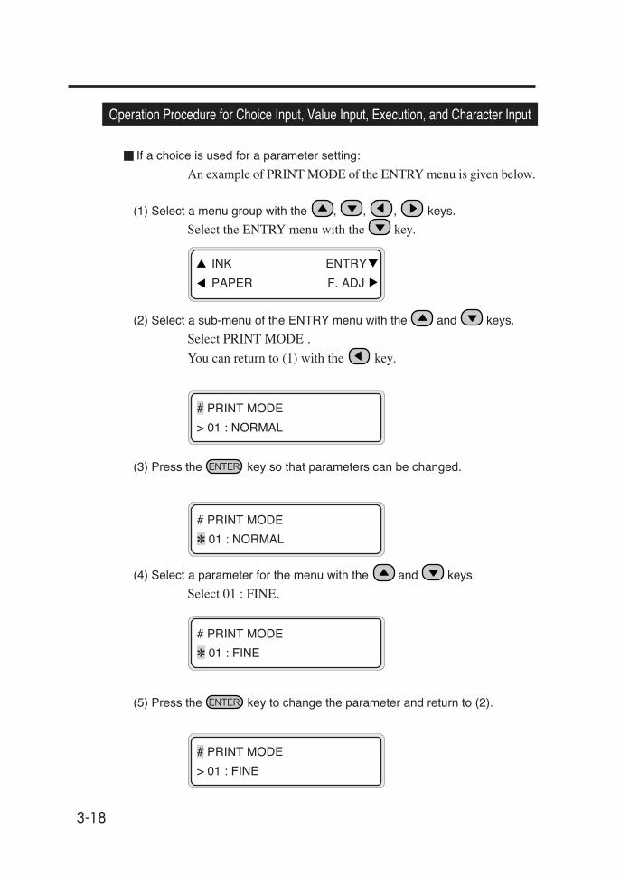
3-18
Operation Procedure for Choice Input, Value Input, Execution, and Character Input
If a choice is used for a parameter setting:
An example of PRINT MODE of the ENTRY menu is given below.
(1) Select a menu group with the , , , keys.
Select the ENTRY menu with the key.
(2) Select a sub-menu of the ENTRY menu with the and keys.
Select PRINT MODE .
You can return to (1) with the key.
(3) Press the key so that parameters can be changed.
(4) Select a parameter for the menu with the and keys.
Select 01 : FINE.
(5) Press the key to change the parameter and return to (2).
# PRINT MODE
> 01 : NORMAL
# PRINT MODE
✽ 01 : NORMAL
# PRINT MODE
✽ 01 : FINE
# PRINT MODE
> 01 : FINE
INK ENTRY
PAPER F. ADJ

3-19
Sect
ion
3 O
pera
tion
Pane
l Men
u O
pera
tions
If a value is input for a parameter setting:
The PAPER FEED ADJ menu of the ADJUST menu is given as an
example.
(1) Select a menu group with the , , , keys.
Select ADJUST with the key.
(2) Select a sub-menu of the ADJUST menu with the and keys.
Select the PAPER FEED ADJ. menu.
You can return to (1) with the key.
(3) Press the key so that parameters can be changed.
(4) Move to the digit to be modified with the and keys.
# PAPER FEED ADJ
> 099. 80%
# PAPER FEED ADJ
✽ 099. 80%
# PAPER FEED ADJ
✽ 099. 80%
(5) Modify the value by pressing the and keys.
(6) Press the key to change the parameter and return to (2).
# PAPER FEED ADJ
✽ 099. 70%
# PAPER FEED ADJ
> 099. 70%
FUNC SYSTEM
ADJUST RESET
Basic Menu Operation in Offline State

3-20
If a parameter is executed:
Case 1: To print
The MENU PRINT menu of the FUNC menu is given as an
example.
(1) Select a menu group with the , , , keys.
Select the FUNC menu with the key.
(2) Select a sub-menu of the FUNC menu with the and keys.
Select MENU PRINT menu.
You can return to (1) with the key.
(3) Press the key.
(4) Press the key to execute the function.
Press the key to return to (2) without executing the function.
(5) After execution, the display returns to (2).
# MENU PRINT
>
# MENU PRINT
✽ OK ?
# MENU PRINT
✽ EXECUTING
FUNC SYSTEM
ADJUST RESET
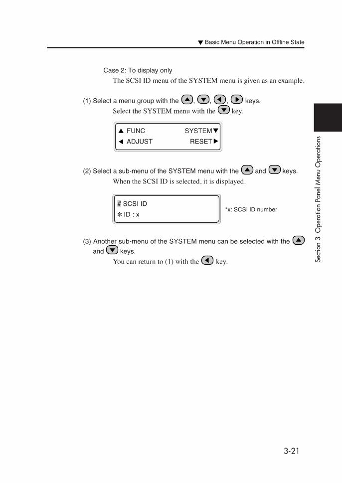
3-21
Sect
ion
3 O
pera
tion
Pane
l Men
u O
pera
tions
Case 2: To display only
The SCSI ID menu of the SYSTEM menu is given as an example.
(1) Select a menu group with the , , , keys.
Select the SYSTEM menu with the key.
(2) Select a sub-menu of the SYSTEM menu with the and keys.
When the SCSI ID is selected, it is displayed.
(3) Another sub-menu of the SYSTEM menu can be selected with the
and keys.
You can return to (1) with the key.
# SCSI ID
✽ ID : x*x: SCSI ID number
FUNC SYSTEM
ADJUST RESET
Basic Menu Operation in Offline State

3-22
If character is input for parameter setting:
The example of NAME of the ENTRY menu is given below.
(1) Select a menu group with the , , , keys.
Select the ENTRY menu with the key.
(2) Select a sub-menu of the ENTRY menu with the and keys.
Select NAME.
(3) Press the key so that the parameter can be changed.
(4) Select a character code group by pressing the and keys
or and keys.
Modify the value by pressing the or key.
(See “Character List” on the next page. )
(5) Move to a digit by pressing the and keys.
Then, modify the value.
INK ENTRY
PAPER F. ADJ
# NAME
✽01 : TYPE01
# NAME
✽01 : CYPE01
# NAME
✽01 : CYPE01
# NAME
>01 : TYPE01
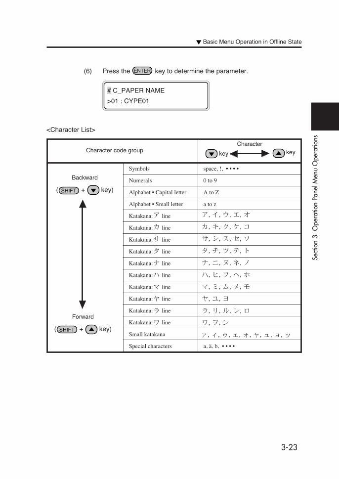
3-23
Sect
ion
3 O
pera
tion
Pane
l Men
u O
pera
tions
(6) Press the key to determine the parameter.
# C_PAPER NAME
>01 : CYPE01
Backward
( + key)
Forward
( + key)
Character code groupCharacter
Symbols space, !, • • • •
Numerals 0 to 9
Alphabet • Capital letter A to Z
Alphabet • Small letter a to z
Katakana: line
Katakana: line
Katakana: line
Katakana: line
Katakana: line
Katakana: line
Katakana: line
Katakana: line
Katakana: line
Katakana: line
Small katakana
Special characters a, ä, b, • • • •
key key
<Character List>
Basic Menu Operation in Offline State

3-24
INK ENTRY
PAPER F. ADJ
Menu Operations
INK Menu
This menu is used to display ink information or replace the ink.
When the key is pressed, information on each color ink is
displayed at three-second intervals.
XX: Color name, such as Bk,
Lm, Lc, Y, M, and C.
YYY: Remaining amount of ink.
ZZ: Date
(1) XX INK indicates the remaining amount of ink.
DATE indicates the manufacture date of the ink cartridge.
(2) When the key is pressed, you can go to the next step
without waiting for three seconds.
(3) When the or key is pressed, display scrolling ends
and the top menu is displayed in offline state.
(4) When the key is pressed, display scrolling ends and the
printer is put online.
(5) When the key is pressed, display scrolling ends and the
printer enters the ink cartridge replacement.
(See Section 2, Replacing Ink Cartridges.)
XX INK REST : YYY%
DATE : ZZ/ZZ/ZZ

3-25
Sect
ion
3 O
pera
tion
Pane
l Men
u O
pera
tions
PAPER Menu
This menu is used to display media information or replace the media.When the key is pressed, information on media is displayed atthree-second intervals.
<Main feed>
X: Media type
Y: Media size
<Sub feed (media roll)>
X: Media type
Y: Media size
<Main feed (media roll) with origin point function valid>
X: Media type
Y: Media size
<Sub feed (media roll) with origin point function valid>
X: Media type
Y: Media size
<Cut Sheet>X: Media type
Y: Media size (mm)
Z: Media length (mm)
<Dual roll>
X: Media type
Y: Media size
INK ENTRY
PAPER F.ADJ
Key
DUAL (XXXXXX)
YYY
MAIN (XXXXXX)
YYY
SUB (XXXXXX)
YYY
MAIN B (XXXXXX)
YYY
SUB B (XXXXXX)
YYY
SHEET (XXXXXX)
YYYYmm x ZZZMM
Menu Operations
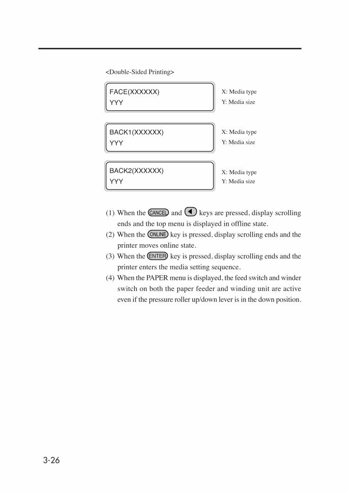
3-26
<Double-Sided Printing>
X: Media type
Y: Media size
X: Media type
Y: Media size
X: Media type
Y: Media size
(1) When the and keys are pressed, display scrolling
ends and the top menu is displayed in offline state.
(2) When the key is pressed, display scrolling ends and the
printer moves online state.
(3) When the key is pressed, display scrolling ends and the
printer enters the media setting sequence.
(4) When the PAPER menu is displayed, the feed switch and winder
switch on both the paper feeder and winding unit are active
even if the pressure roller up/down lever is in the down position.
FACE(XXXXXX)
YYY
BACK2(XXXXXX)
YYY
BACK1(XXXXXX)
YYY
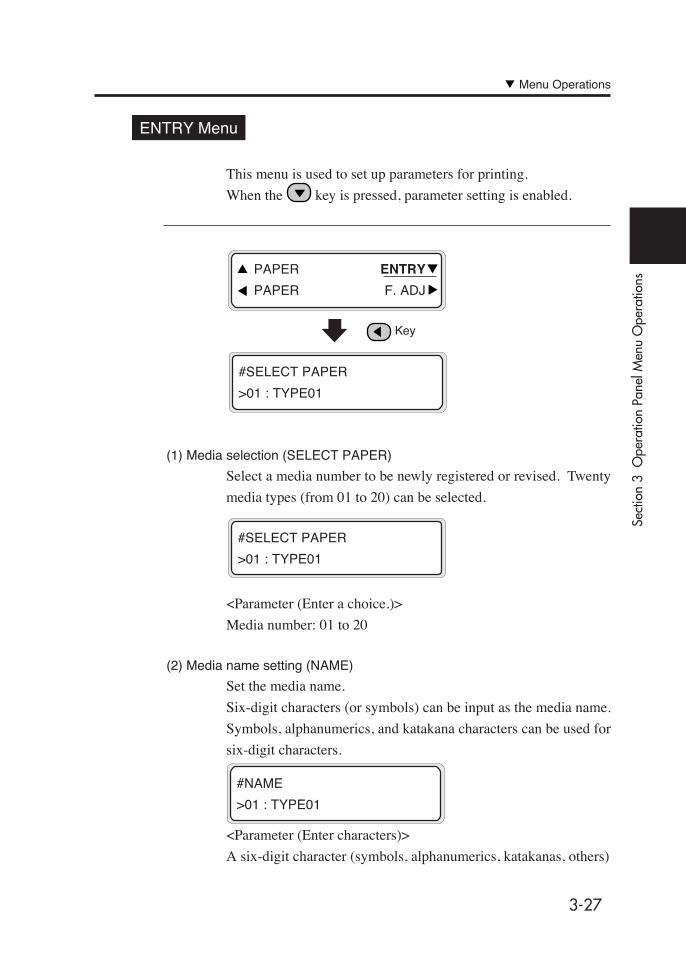
3-27
Sect
ion
3 O
pera
tion
Pane
l Men
u O
pera
tions
ENTRY Menu
This menu is used to set up parameters for printing.
When the key is pressed, parameter setting is enabled.
(1) Media selection (SELECT PAPER)
Select a media number to be newly registered or revised. Twenty
media types (from 01 to 20) can be selected.
<Parameter (Enter a choice.)>
Media number: 01 to 20
(2) Media name setting (NAME)
Set the media name.
Six-digit characters (or symbols) can be input as the media name.
Symbols, alphanumerics, and katakana characters can be used for
six-digit characters.
<Parameter (Enter characters)>
A six-digit character (symbols, alphanumerics, katakanas, others)
#SELECT PAPER
>01 : TYPE01
PAPER ENTRY
PAPER F. ADJ
Key
#SELECT PAPER
>01 : TYPE01
#NAME
>01 : TYPE01
Menu Operations

3-28
(3) Feed correction value (Unit: %)
Set the feed correction value for the selected media.
<Parameter (Enter a value)>XXX.XX% (97.00 to 103.00%)
(4) Scan waiting time (SCAN WAIT TIME) (Unit: second)
Set the media scanning wait time for the selected media.
<Parameter (Enter a value)>Input three decimal digits in second units. (0 to 999 seconds)
(5) Print mode setting
Set a print mode for the selected media.
<Parameter (Enter a choice)>NORMAL: (4-pass)FINE: (8-pass)DENSITY: (8-pass)3 TIMES: (12-pass)H-QUALITY 2: (16-pass)H-DENSITY 2: (16-pass)DRAFT: (2-pass)FAST: (4-pass)F-H-QUALITY: (8-pass)F-H-DENSITY: (8-pass)F-3 TIMES: (12-pass)F-H-QUAL 2: (16-pass)F-H-DENS 2: (4-pass)
For further information on parameters, see page 4-2 "Print
Modes."
#FEED ADJUST
>01 : 100.00%
BASE=099.92%
>01 : 100.00%
#SCAN WAIT TIME
>01 : 000sec
#PRINT MODE
NORMAL
HINT
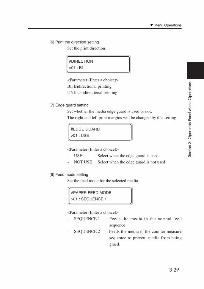
3-29
Sect
ion
3 O
pera
tion
Pane
l Men
u O
pera
tions
(6) Print the direction setting
Set the print direction.
<Parameter (Enter a choice)>
BI: Bidirectional printing
UNI: Unidirectional printing
(7) Edge guard setting
Set whether the media edge guard is used or not.
The right and left print margins will be changed by this setting.
<Parameter (Enter a choice)>
- USE : Select when the edge guard is used.
- NOT USE : Select when the edge guard is not used.
(8) Feed mode setting
Set the feed mode for the selected media.
<Parameter (Enter a choice)>
- SEQUENCE 1 : Feeds the media in the normal feed
sequence.
- SEQUENCE 2 : Feeds the media in the counter measure
sequence to prevent media from being
glued.
#DIRECTION
>01 : BI
#EDGE GUARD
>01 : USE
#PAPER FEED MODE
>01 : SEQUENCE 1
Menu Operations
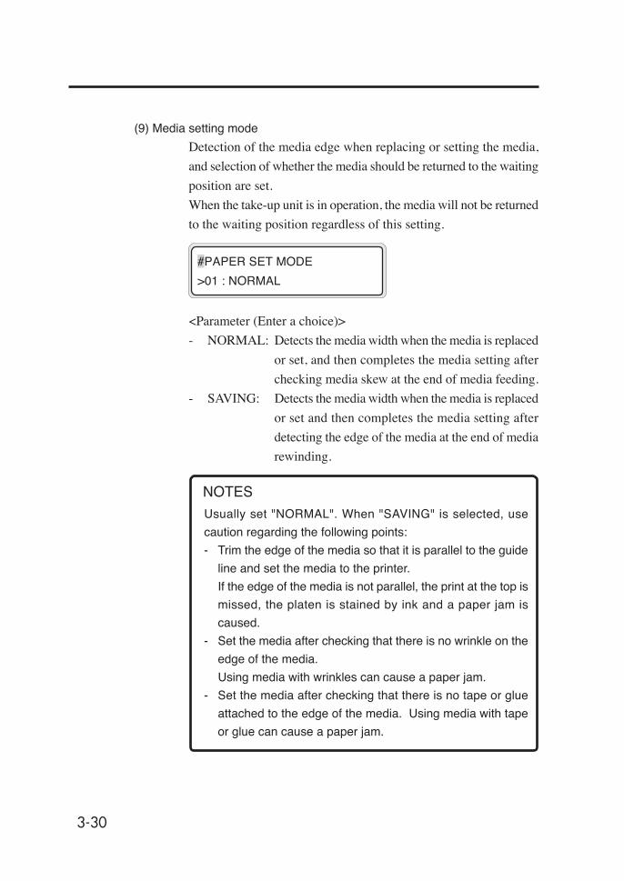
3-30
(9) Media setting mode
Detection of the media edge when replacing or setting the media,
and selection of whether the media should be returned to the waiting
position are set.
When the take-up unit is in operation, the media will not be returned
to the waiting position regardless of this setting.
<Parameter (Enter a choice)>
- NORMAL: Detects the media width when the media is replaced
or set, and then completes the media setting after
checking media skew at the end of media feeding.
- SAVING: Detects the media width when the media is replaced
or set and then completes the media setting after
detecting the edge of the media at the end of media
rewinding.
Usually set "NORMAL". When "SAVING" is selected, use
caution regarding the following points:
- Trim the edge of the media so that it is parallel to the guide
line and set the media to the printer.
If the edge of the media is not parallel, the print at the top is
missed, the platen is stained by ink and a paper jam is
caused.
- Set the media after checking that there is no wrinkle on the
edge of the media.
Using media with wrinkles can cause a paper jam.
- Set the media after checking that there is no tape or glue
attached to the edge of the media. Using media with tape
or glue can cause a paper jam.
#PAPER SET MODE
>01 : NORMAL
NOTES
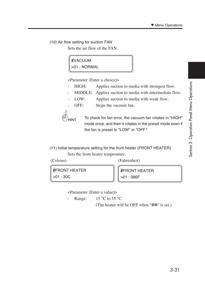
3-31
Sect
ion
3 O
pera
tion
Pane
l Men
u O
pera
tions
(10) Air flow setting for suction FAN
Sets the air flow of the FAN.
<Parameter (Enter a choice)>
- HIGH: Applies suction to media with strongest flow.
- MIDDLE: Applies suction to media with intermediate flow.
- LOW: Applies suction to media with weak flow.
- OFF: Stops the vacuum fan.
To check for fan error, the vacuum fan rotates in "HIGH"
mode once, and then it rotates in the preset mode even if
the fan is preset to "LOW" or "OFF."
(11) Initial temperature setting for the front heater (FRONT HEATER)
Sets the front heater temperature.
(Celsius) (Fahrenheit)
<Parameter (Enter a value)>
- Range: 15 °C to 55 °C
(The heater will be OFF when "✽✽" is set.)
#FRONT HEATER
>01 : 086F
#FRONT HEATER
>01 : 30C
#VACUUM
>01 : NORMAL
HINT
Menu Operations
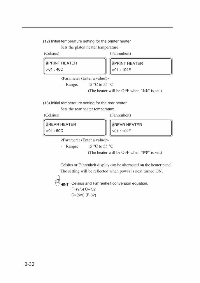
3-32
(12) Initial temperature setting for the printer heater
Sets the platen heater temperature.
(Celsius) (Fahrenheit)
<Parameter (Enter a value)>
- Range: 15 °C to 55 °C
(The heater will be OFF when "✽✽" is set.)
(13) Initial temperature setting for the rear heater
Sets the rear heater temperature.
(Celsius) (Fahrenheit)
<Parameter (Enter a value)>
- Range: 15 °C to 55 °C
(The heater will be OFF when "✽✽" is set.)
Celsius or Fahrenheit display can be alternated on the heater panel.
The setting will be reflected when power is next turned ON.
Celsius and Fahrenheit conversion equation.
F=(9/5) C+ 32
C=(5/9) (F-32)
#PRINT HEATER
>01 : 104F
#PRINT HEATER
>01 : 40C
#REAR HEATER
>01 : 122F
#REAR HEATER
>01 : 50C
HINT

3-33
Sect
ion
3 O
pera
tion
Pane
l Men
u O
pera
tions
(14) Color stripe setting (COLOR STRIPE)
Sets color stripe print ON/OFF.
<Parameter (Enter a choice)>
- ON: Prints the color stripe print on the origin side.
- OFF: Does not print the color stripe on the origin side.
(15) Head action mode setting
Selects a head action mode.
<Parameter (Enter a choice)>
- NORMAL: Use this usually.
- HIGHLIGHT: Use this for print gradation data.
#COLOR STRIPE
>01 : ON
- If the color stripe is not set, dot-off in printing may occur.
It is recommended to set the color stripe for printing, if
practicable.
- The color stripe is printed on the test print regardless of
this setting.
NOTES
If a pattern having very low printing rate in even one color is
printed continuously at high temperature, gaps in printing may
occur at a low printing rate color. In this case, set the head
mode to HILIGHT PRIORITY.
NOTE
#HEAD MOTION
>01 : NORMAL
Menu Operations
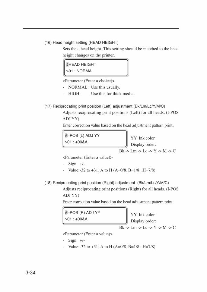
3-34
(16) Head height setting (HEAD HEIGHT)
Sets the a head height. This setting should be matched to the head
height changes on the printer.
<Parameter (Enter a choice)>
- NORMAL: Use this usually.
- HIGH: Use this for thick media.
(17) Reciprocating print position (Left) adjustment (Bk/Lm/Lc/Y/M/C)
Adjusts reciprocating print positions (Left) for all heads. (I-POS
ADJ YY)
Enter correction value based on the head adjustment pattern print.
YY: Ink color
Display order:
Bk -> Lm -> Lc -> Y -> M -> C
<Parameter (Enter a value)>
- Sign: +/-
- Value:-32 to +31, A to H (A=0/8, B=1/8...H=7/8)
(18) Reciprocating print position (Right) adjustment (Bk/Lm/Lc/Y/M/C)
Adjusts reciprocating print positions (Right) for all heads. (I-POS
ADJ YY)
Enter correction value based on the head adjustment pattern print.
YY: Ink color
Display order:
Bk -> Lm -> Lc -> Y -> M -> C
<Parameter (Enter a value)>
- Sign: +/-
- Value:-32 to +31, A to H (A=0/8, B=1/8...H=7/8)
#HEAD HEIGHT
>01 : NORMAL
#I-POS (R) ADJ YY
>01 : +00&A
#I-POS (L) ADJ YY
>01 : +00&A

3-35
Sect
ion
3 O
pera
tion
Pane
l Men
u O
pera
tions
(19) For fine draft reciprocating print position (left) adjustment (Bk/Lm/Lc/Y/M/C)
Adjusts reciprocating print position (left) of all heads for fine draft
(main scan 540 dpi mode). Enter correction value based on the
head adjustment pattern print.
YY: Ink color
Display order: Bk -> Lm -> Lc -> Y -> M -> C
<Parameter (Enter a value)>
- Sign: +/-
- Value: -32 to +31, A to H (A=0/8, B=1/8, ... H=7/8)
(20) For fine draft reciprocating print position (right) adjustment (Bk/Lm/Lc/Y/M/C)
Adjusts reciprocating print position (right) of all heads for fine draft
(main scan 540 dpi mode). Enter correction value based on the
head adjustment pattern print.
YY: Ink color
Display order: Bk -> Lm -> Lc -> Y -> M -> C
<Parameter (Enter a value)>
- Sign: +/-
- Value: -32 to +31, A to H (A=0/8, B=1/8, ... H=7/8)
# POS (L) ADJ2 YY
>+00&A
# POS (R) ADJ2 YY
>+00&A
Menu Operations

3-36
(21) Cleaning mode
Selects a cleaning mode to be performed automatically during
printing.
<Parameter (Enter a value)>
MODE 1: Performs cleaning automatically according to the
print history record at the start of printing or at the
end of printing.
MODE 2: Performs cleaning automatically at regular intervals
during printing. (Select this mode when using
media such as PVC sensitive to the heater
temperature.)
MODE 3: Performs cleaning automatically at regular intervals
during printing. (Select this mode when
using media such as tarpaulin insensitive to the
heater temperature.)
- When sequence 2 has been set as the media feed mode,
the printer performs the same as in "mode 1" even if "mode
2" is selected.
- When selecting mode 2, separator lines will be generated
on the print because cleaning is performed during printing.
These lines can be adjusted with media back correction
value input in the "BACK ADJUS" menu.
However, these lines may be shifted depending on the
media, and in such a case, use "mode 1" or "mode 3".
- In case of "mode 2", complete printing of the image before
and after the separator line, and then perform cleaning.
- In case of "mode 3", perform cleaning with the separator
line in the midway of print path status.
# CLEANING MODE
>01: MODE 1
NOTES

3-37
Sect
ion
3 O
pera
tion
Pane
l Men
u O
pera
tions
(22) Media back feed correction value (unit: pulses)
Sets the media back feed correction value for the selected media.
Adjusts separator lines when the image is separated due to automatic
cleaning during printing.
<Parameter (Enter a value)>
- ±2000 pulses (+5 mm)
- 1 pulses=2.5 µm
(23) Priority setting (media feed correction value)
Selects the priority of the media feed correction value.
<Parameter (Enter a value)>
- DATA: Gives priority to data.
- PANEL: Gives priority to the panel.
(24) Priority setting (PRINT MODE)
Selects the priority of the print mode.
<Parameter (Enter a value)>
- DATA: Gives priority to data.
- PANEL: Gives priority to the panel.
#PRIORITY MODE
>01 : DATA
#PRIORITY FEED
>01 : DATA
# BACK ADJUST
>01: +0000 PULSE
Menu Operations
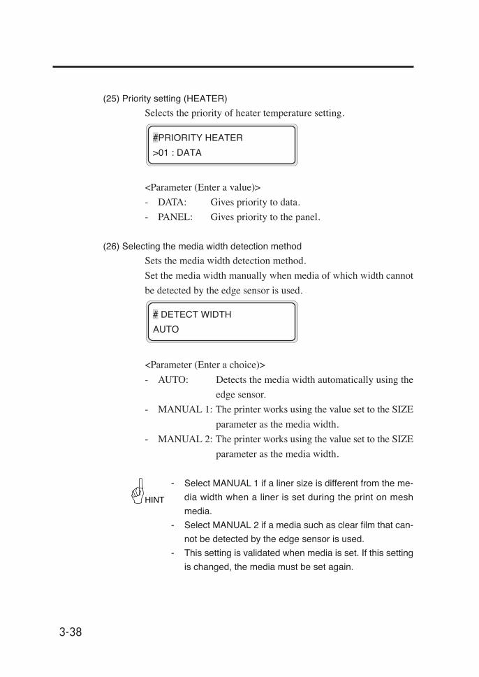
3-38
(25) Priority setting (HEATER)
Selects the priority of heater temperature setting.
<Parameter (Enter a value)>
- DATA: Gives priority to data.
- PANEL: Gives priority to the panel.
(26) Selecting the media width detection method
Sets the media width detection method.
Set the media width manually when media of which width cannot
be detected by the edge sensor is used.
<Parameter (Enter a choice)>
- AUTO: Detects the media width automatically using the
edge sensor.
- MANUAL 1: The printer works using the value set to the SIZE
parameter as the media width.
- MANUAL 2: The printer works using the value set to the SIZE
parameter as the media width.
- Select MANUAL 1 if a liner size is different from the me-
dia width when a liner is set during the print on mesh
media.
- Select MANUAL 2 if a media such as clear film that can-
not be detected by the edge sensor is used.
- This setting is validated when media is set. If this setting
is changed, the media must be set again.
#PRIORITY HEATER
>01 : DATA
# DETECT WIDTH
AUTO
HINT

3-39
Sect
ion
3 O
pera
tion
Pane
l Men
u O
pera
tions
(27) Setting the media width size
Select the media width size.
The printer works using the value set here as the media width when
"DETECT WIDTH" is set to MANUAL.
If this item is set, the same value is automatically set to SIZE 2.
<Parameter (Enter a value)>
Value: 914 to 2642
- This setting is validated when media is set. If this setting
is changed, the media must be set again.
(28) Setting media width size 2
Select the media width size (mesh printing liner)
The printer works using the value set here as the media width when
"DETECT WIDTH" is set to MANUAL.
<Parameter (Enter a value)>
Value: 914 to 2642
- This setting is validated when media is set. If this setting
is changed, the media must be set again.
(29) Peeling operation
Select whether peeling operation is executed on the selected media.
Numbers 01 to 20 of the registered media can be selected.
<Parameter (Enter a choice)>
- ON: Media is fed in usual operation mode.
- OFF: Media peeling operation is executed after standby
operation at the start of printing.
# SIZE
>01: 2642mm
# SIZE 2
>01: 2642mm
# PEEL MODE
>01: OFF
HINT
HINT
Menu Operations
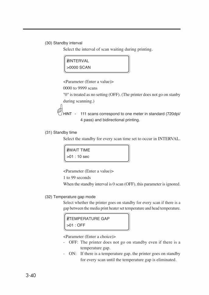
3-40
(30) Standby interval
Select the interval of scan waiting during printing.
<Parameter (Enter a value)>
0000 to 9999 scans
"0" is treated as no setting (OFF). (The printer does not go on stanby
during scanning.)
- 111 scans correspond to one meter in standard (720dpi/
4 pass) and bidirectional printing.
(31) Standby time
Select the standby for every scan time set to occur in INTERVAL.
<Parameter (Enter a value)>
1 to 99 seconds
When the standby interval is 0 scan (OFF), this parameter is ignored.
(32) Temperature gap modeSelect whether the printer goes on standby for every scan if there is agap between the media print heater set temperature and head temperature.
<Parameter (Enter a choice)>- OFF: The printer does not go on standby even if there is a
temperature gap.- ON: If there is a temperature gap, the printer goes on standby
for every scan until the temperature gap is eliminated.
#INTERVAL
>0000 SCAN
HINT
#WAIT TIME
>01 : 10 sec
#TEMPERATURE GAP
>01 : OFF

3-41
Sect
ion
3 O
pera
tion
Pane
l Men
u O
pera
tions
(33) Deleting registrated media (DELETE MEDIA)
Deletes a registered media.
Registered media from 01 to 20 can be selected.
The registered media 01 is defined as the standard media. This
cannot be deleted.
When the key is pressed, confirmation guidance will be
displayed.
(34) Parameter copy source
Register the copy source of the registered media numbers.
Setting of this parameter and (35) Parameter copy destination
copies the registered media information.
<Parameter (Enter a choice)>
- Value: 01 to 20
However, only the registered numbers are displayed.
(35) Parameter copy destination
Select the copy destination number of the registered media.
<Parameter (Enter a choice)>
- Value: 01 to 20
"✽" is displayed for an already registered number.
#DELETE PAPER
>01 : TYPE02
#DELETE PAPER
>01 : TYPE02 OK?
# COPY SOUCE
>01
# COPY DEST
>01→01✽
Menu Operations

3-42
Parameter copy method
(1) Select the copy source.
Select the copy source parameter with the
or key.
Enter the copy source parameter with the
key.
(2) Select the copy destination
Select the copy destination parameter
with the or key.(As copy destination numbers, 01 to 20 aredisplayed.)
"✽" is displayed for already registered copy
destination number.
Enter the copy destination parameter with
the key.
Execute a parameter copy with the
key.
- When the key is pressed, the initial menu comes back.
, Key
#COPY DEST
>13→01✽
#COPY DEST
✽13→01✽
, Key
#COPY DEST
✽13→20
#COPY DEST
✽13→20 OK?
#COPY DEST
✽13→20 OK✽
#COPY SOUCE
>01
#COPY SOUCE
✽01
#COPY SOUCE
✽13
#COPY SOUCE
>13
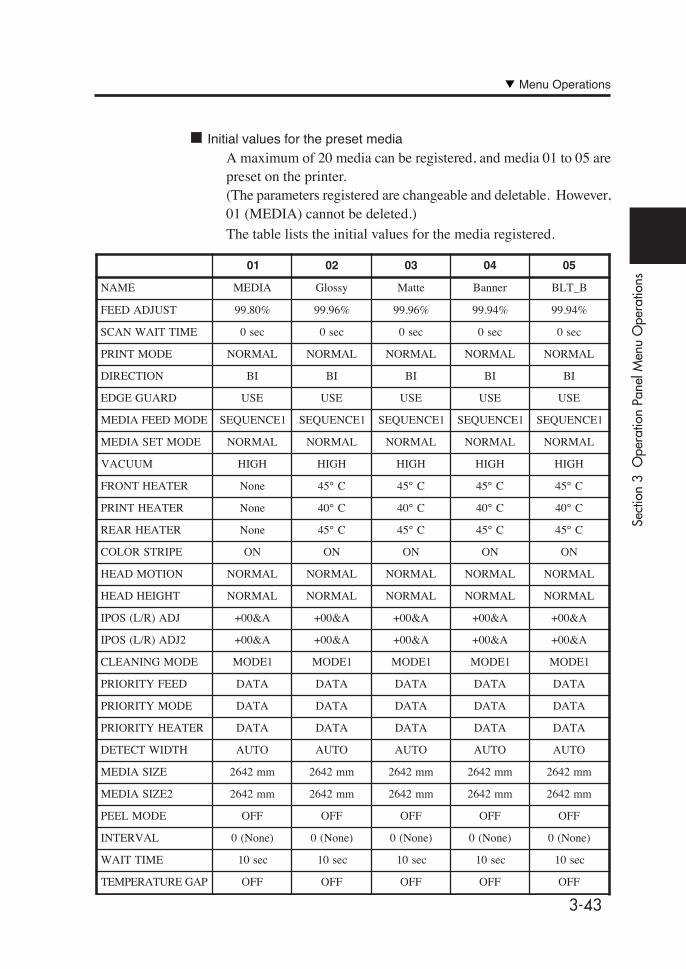
3-43
Sect
ion
3 O
pera
tion
Pane
l Men
u O
pera
tions
Initial values for the preset mediaA maximum of 20 media can be registered, and media 01 to 05 arepreset on the printer.(The parameters registered are changeable and deletable. However,01 (MEDIA) cannot be deleted.)The table lists the initial values for the media registered.
01 02 03 04 05
NAME MEDIA Glossy Matte Banner BLT_B
FEED ADJUST 99.80% 99.96% 99.96% 99.94% 99.94%
SCAN WAIT TIME 0 sec 0 sec 0 sec 0 sec 0 sec
PRINT MODE NORMAL NORMAL NORMAL NORMAL NORMAL
DIRECTION BI BI BI BI BI
EDGE GUARD USE USE USE USE USE
MEDIA FEED MODE SEQUENCE1 SEQUENCE1 SEQUENCE1 SEQUENCE1 SEQUENCE1
MEDIA SET MODE NORMAL NORMAL NORMAL NORMAL NORMAL
VACUUM HIGH HIGH HIGH HIGH HIGH
FRONT HEATER None 45° C 45° C 45° C 45° C
PRINT HEATER None 40° C 40° C 40° C 40° C
REAR HEATER None 45° C 45° C 45° C 45° C
COLOR STRIPE ON ON ON ON ON
HEAD MOTION NORMAL NORMAL NORMAL NORMAL NORMAL
HEAD HEIGHT NORMAL NORMAL NORMAL NORMAL NORMAL
IPOS (L/R) ADJ +00&A +00&A +00&A +00&A +00&A
IPOS (L/R) ADJ2 +00&A +00&A +00&A +00&A +00&A
CLEANING MODE MODE1 MODE1 MODE1 MODE1 MODE1
PRIORITY FEED DATA DATA DATA DATA DATA
PRIORITY MODE DATA DATA DATA DATA DATA
PRIORITY HEATER DATA DATA DATA DATA DATA
DETECT WIDTH AUTO AUTO AUTO AUTO AUTO
MEDIA SIZE 2642 mm 2642 mm 2642 mm 2642 mm 2642 mm
MEDIA SIZE2 2642 mm 2642 mm 2642 mm 2642 mm 2642 mm
PEEL MODE OFF OFF OFF OFF OFF
INTERVAL 0 (None) 0 (None) 0 (None) 0 (None) 0 (None)
WAIT TIME 10 sec 10 sec 10 sec 10 sec 10 sec
TEMPERATURE GAP OFF OFF OFF OFF OFF
Menu Operations
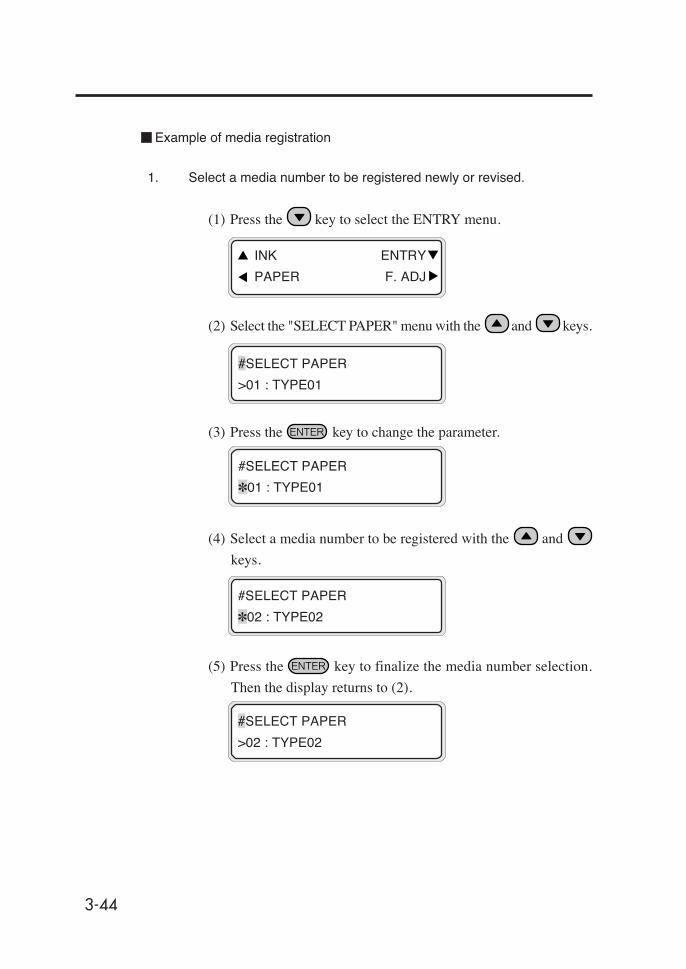
3-44
Example of media registration
1. Select a media number to be registered newly or revised.
(1) Press the key to select the ENTRY menu.
(2) Select the "SELECT PAPER" menu with the and keys.
(3) Press the key to change the parameter.
(4) Select a media number to be registered with the and
keys.
(5) Press the key to finalize the media number selection.
Then the display returns to (2).
INK ENTRY
PAPER F. ADJ
#SELECT PAPER
>01 : TYPE01
#SELECT PAPER
✽01 : TYPE01
#SELECT PAPER
✽02 : TYPE02
#SELECT PAPER
>02 : TYPE02

3-45
Sect
ion
3 O
pera
tion
Pane
l Men
u O
pera
tions
2. Example of parameter setting
In this example, a feed correction value will be entered.
(1) Select the "FEED ADJUST" menu with the and keys.
(2) Press the key and revise the parameter.
- Determine the feed correction value by printing the feed
adjustment pattern.
(3) Press the key to display the message.
(This message will be displayed at new registration only.)
(4) When the key is pressed, media number 02 is registered
newly and a "✽" mark that shows the media has already been
registered is displayed. Then the display returns to (1).
Press the key to stop new registration. The display
returns to (1).
#FEED ADJUST
>02 : 099.80%
#FEED ADJUST
*02 : 099.80%
NOTE
#FEED ADJUST
>02 : ENTRY OK?
#FEED ADJUST
>02 : 099.80% ✽
Menu Operations
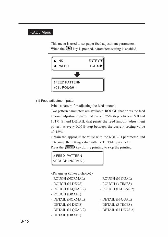
3-46
F.ADJ Menu
This menu is used to set paper feed adjustment parameters.
When the key is pressed, parameters setting is enabled.
(1) Feed adjustment pattern
Prints a pattern for adjusting the feed amount.
Two pattern parameters are available, ROUGH that prints the feed
amount adjustment pattern at every 0.25% step between 99.0 and
101.0 %, and DETAIL that prints the feed amount adjustment
pattern at every 0.06% step between the current setting value
±0.12%.
Obtain the approximate value with the ROUGH parameter, and
determine the setting value with the DETAIL parameter.
Press the key during printing to stop the printing.
<Parameter (Enter a choice)>
- ROUGH (NORMAL) - ROUGH (H-QUAL)
- ROUGH (H-DENS) - ROUGH (3 TIMES)
- ROUGH (H-QUAL 2) - ROUGH (H-DENS 2)
- ROUGH (DRAFT)
- DETAIL (NORMAL) - DETAIL (H-QUAL)
- DETAIL (H-DENS) - DETAIL (3 TIMES)
- DETAIL (H-QUAL 2) - DETAIL (H-DENS 2)
- DETAIL (DRAFT)
INK ENTRY
PAPER F.ADJ
#FEED PATTERN
>01 : ROUGH 1
# FEED PATTERN
>ROUGH (NORMAL)

3-47
Sect
ion
3 O
pera
tion
Pane
l Men
u O
pera
tions
(2) Feed correction value setting
Sets the feed correction value.
Enter a correction value according to the feed adjustment pattern
print.
The BASE value is displayed alternately on the 1st line.
<Parameter (Enter a value)>
xxx.xx% (97.00 to 103.00)
- Select the parameter according to respective print modes
by referring to the following table:
#FEED ADJUST
>01 : 099.80%
BASE=099.88%
>01 : 099.80%
HINT
sedomtnirPsretemaraP
HGUOR)%0.101ot0.99nipets%52.0(
LIATED)%21.0±eulavtesnipets%60.0(
LAMRON )LAMRON(HGUOR )LAMRON(LIATED
YTILAUQ-H )YTILAUQ-H(HGUOR )YTILAUQ-H(LIATED
YTISNED-H )YTISNED-H(HGUOR )YTISNED-H(LIATED
SEMIT3 )SEMIT3(HGUOR )SEMIT3(LIATED
2YTILAUQ-H )2LAUQ-H(HGUOR )2LAUQ-H(LIATED
2YTISNED-H )2SNED-H(HGUOR )2SNED-H(LIATED
TFARD )TFARD(HGUOR )TFARD(LIATED
TSAF )LAMRON(HGUOR )LAMRON(LIATED
YTILAUQ-H-F )YTILAUQ-H(HGUOR )YTILAUQ-H(LIATED
YTISNED-H-F )YTISNED-H(HGUOR )YTISNED-H(LIATED
SEMIT3-F )SEMIT3(HGUOR )SEMIT3(LIATED
2LAUQ-H-F )2LAUQ-H(HGUOR )2LAUQ-H(LIATED
2SNED-H-F )2SNED-H(HGUOR )2SNED-H(LIATED
TFARDENIF )LAMRON(HGUOR )LAMRON(LIATED
Menu Operations
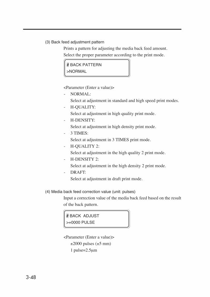
3-48
(3) Back feed adjustment pattern
Prints a pattern for adjusting the media back feed amount.
Select the proper parameter according to the print mode.
<Parameter (Enter a value)>
- NORMAL:
Select at adjustment in standard and high speed print modes.
- H-QUALITY:
Select at adjustment in high quality print mode.
- H-DENSITY:
Select at adjustment in high density print mode.
- 3 TIMES:
Select at adjustment in 3 TIMES print mode.
- H-QUALITY 2:
Select at adjustment in the high quality 2 print mode.
- H-DENSITY 2:
Select at adjustment in the high density 2 print mode.
- DRAFT:
Select at adjustment in draft print mode.
(4) Media back feed correction value (unit: pulses)
Input a correction value of the media back feed based on the result
of the back pattern.
<Parameter (Enter a value)>
±2000 pulses (±5 mm)
1 pulse=2.5µm
# BACK PATTERN
>NORMAL
# BACK ADJUST
>+0000 PULSE

3-49
Sect
ion
3 O
pera
tion
Pane
l Men
u O
pera
tions
SERVICE Menu
This menu is used to maintain the cap and the wiper as well as to
clean the ink path.
When the key is pressed, the service menu will be operable.
(1) Moving wiper to manual cleaning position
The wiper blade is lifted so that you can clean the wiper blade
manually.
<Parameter (Execution form)>
None
(2) Moving capping unit to manual cleaning position
Moves the print head carriage to the wiper position so that you can
clean the cap unit manually.
<Parameter (Execution form)>
None
#WIPER CLEANING
>
#CAP CLEANING
>
SERVICE FEED
CLEANING
#WIPER CLEANING
>
key
Menu Operations
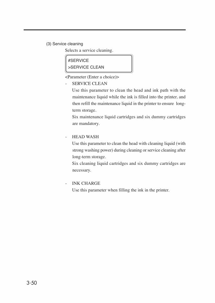
3-50
(3) Service cleaning
Selects a service cleaning.
<Parameter (Enter a choice)>
- SERVICE CLEAN
Use this parameter to clean the head and ink path with the
maintenance liquid while the ink is filled into the printer, and
then refill the maintenance liquid in the printer to ensure long-
term storage.
Six maintenance liquid cartridges and six dummy cartridges
are mandatory.
- HEAD WASH
Use this parameter to clean the head with cleaning liquid (with
strong washing power) during cleaning or service cleaning after
long-term storage.
Six cleaning liquid cartridges and six dummy cartridges are
necessary.
- INK CHARGE
Use this parameter when filling the ink in the printer.
#SERVICE
>SERVICE CLEAN
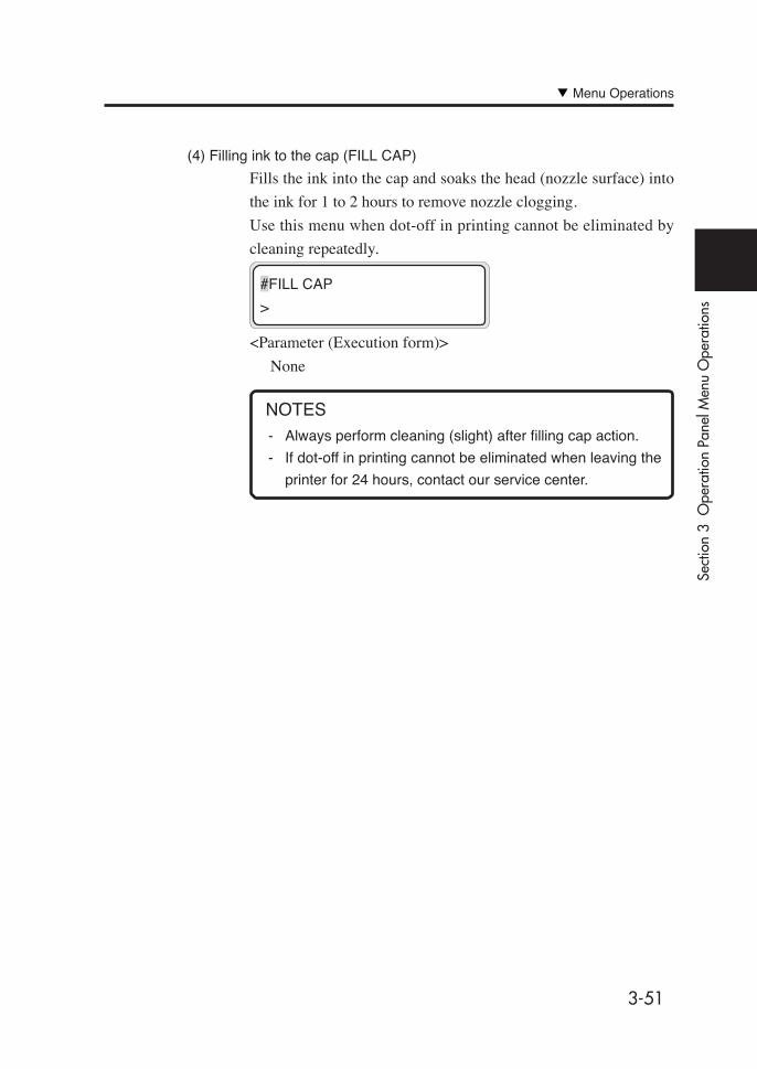
3-51
Sect
ion
3 O
pera
tion
Pane
l Men
u O
pera
tions
(4) Filling ink to the cap (FILL CAP)
Fills the ink into the cap and soaks the head (nozzle surface) into
the ink for 1 to 2 hours to remove nozzle clogging.
Use this menu when dot-off in printing cannot be eliminated by
cleaning repeatedly.
<Parameter (Execution form)>
None
- Always perform cleaning (slight) after filling cap action.
- If dot-off in printing cannot be eliminated when leaving the
printer for 24 hours, contact our service center.
NOTES
#FILL CAP
>
Menu Operations
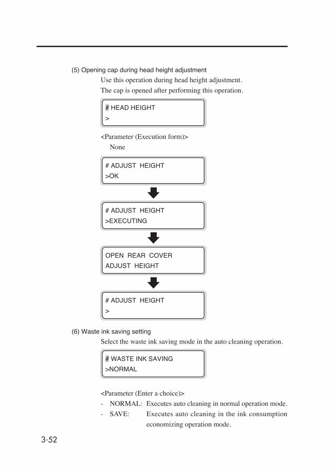
3-52
(5) Opening cap during head height adjustment
Use this operation during head height adjustment.
The cap is opened after performing this operation.
<Parameter (Execution form)>
None
# HEAD HEIGHT
>
# ADJUST HEIGHT
>OK
# ADJUST HEIGHT
>EXECUTING
OPEN REAR COVER
ADJUST HEIGHT
# ADJUST HEIGHT
>
(6) Waste ink saving setting
Select the waste ink saving mode in the auto cleaning operation.
<Parameter (Enter a choice)>
- NORMAL: Executes auto cleaning in normal operation mode.
- SAVE: Executes auto cleaning in the ink consumption
economizing operation mode.
# WASTE INK SAVING
>NORMAL

3-53
Sect
ion
3 O
pera
tion
Pane
l Men
u O
pera
tions
CLEANING Menu
This menu is used to clean the printer head.
When the key is pressed, the cleaning menu appears.
<Parameter (Enter a choice)>
- NORMAL: Cleans the head normally.
- STRONG: Cleans the head strongly.
See Section 2, Head Cleaning for details.
SERVICE FEED
CLEANING
#CLEANING
>NORMAL
key
Menu Operations
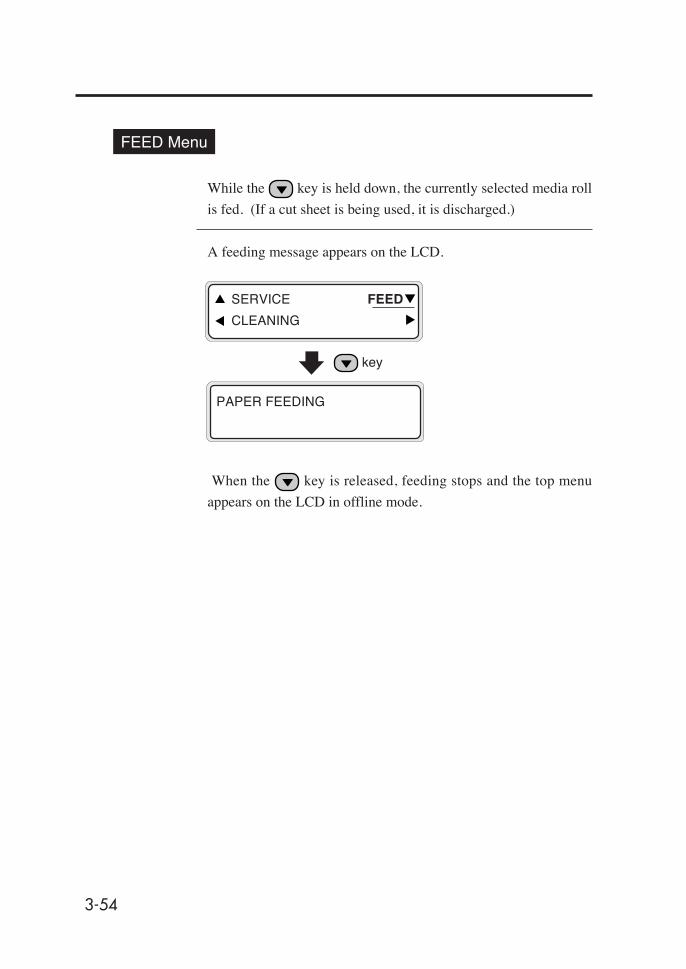
3-54
PAPER FEEDING
FEED Menu
While the key is held down, the currently selected media roll
is fed. (If a cut sheet is being used, it is discharged.)
A feeding message appears on the LCD.
When the key is released, feeding stops and the top menu
appears on the LCD in offline mode.
SERVICE FEED
CLEANING
key

3-55
Sect
ion
3 O
pera
tion
Pane
l Men
u O
pera
tions
FUNC Menu
This menu is used to execute functions provided for the printer.
When the key is pressed, functions can be executed.
(1) Menu print (MENU PRINT)
Prints information on the printer and panel settings.
<Parameter (execution form)>
None
(2) Printing error log information (ERROR LOG PRINT)
Prints error log information saved in the printer.
<Parameter (execution form)>
None
#MENU PRINT
>
FUNC SYSTEM
ADJUST RESET
key
#MENU PRINT
>
#ERROR LOG PRINT
>
Menu Operations
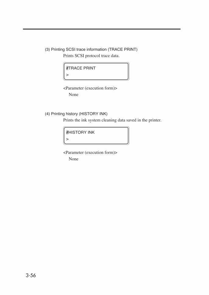
3-56
(3) Printing SCSI trace information (TRACE PRINT)
Prints SCSI protocol trace data.
<Parameter (execution form)>
None
(4) Printing history (HISTORY INK)
Prints the ink system cleaning data saved in the printer.
<Parameter (execution form)>
None
#TRACE PRINT
>
#HISTORY INK
>
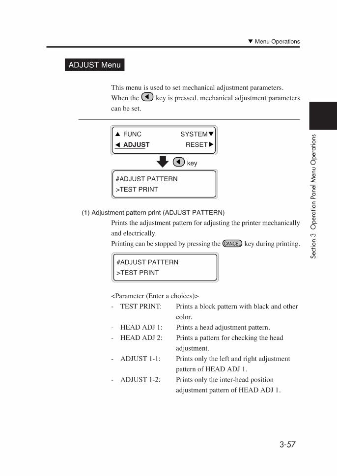
3-57
Sect
ion
3 O
pera
tion
Pane
l Men
u O
pera
tions
ADJUST Menu
This menu is used to set mechanical adjustment parameters.
When the key is pressed, mechanical adjustment parameters
can be set.
(1) Adjustment pattern print (ADJUST PATTERN)
Prints the adjustment pattern for adjusting the printer mechanically
and electrically.
Printing can be stopped by pressing the key during printing.
<Parameter (Enter a choices)>
- TEST PRINT: Prints a block pattern with black and other
color.
- HEAD ADJ 1: Prints a head adjustment pattern.
- HEAD ADJ 2: Prints a pattern for checking the head
adjustment.
- ADJUST 1-1: Prints only the left and right adjustment
pattern of HEAD ADJ 1.
- ADJUST 1-2: Prints only the inter-head position
adjustment pattern of HEAD ADJ 1.
#ADJUST PATTERN
>TEST PRINT
FUNC SYSTEM
ADJUST RESET
key
#ADJUST PATTERN
>TEST PRINT
Menu Operations

3-58
- ADJUST 1-3: Prints only the reciprocating adjustment
pattern of HEAD ADJ 1.
- ADJUST 1-4: Prints the fine draft reciprocating adjustment
pattern of HEAD ADJ 1.
- ADJUST 2-1: Prints the phase, left and right, and inter-head
position adjustment patterns of HEAD ADJ 2.
- ADJUST 2-2: Prints only the reciprocating adjustment
pattern of HEAD ADJ 2.
- ADJUST 2-3: Prints the fine draft reciprocating adjustment
pattern of HEAD ADJ 2.
(2) Nozzle jet position adjustment (Bk/Lm/Lc/Y/M/C) (L/R ADJ YY)
Adjusts the nozzle jet position.
Enter a correction value according to the head adjustment pattern.
YY: Ink color
Display order:
Bk -> Lm -> Lc -> Y -> M -> C
<Parameter (Enter a value)>
- Sign: +/-
- Value:-32 to +31, A to H (A=0/8, B=1/8...H=7/8)
#L/R ADJ YY
>+00&A

3-59
Sect
ion
3 O
pera
tion
Pane
l Men
u O
pera
tions
(3) Head position adjustment (Lm/Lc/Y/M/C) (H-POS ADJ YY)
Adjusts the head position in the scanning direction.
Enter a correction value according to the head adjustment pattern.
YY: Ink color
Display order:
Bk -> Lm -> Lc -> Y -> M -> C
<Parameter (Enter a value)>
- Sign: +/-
- Value:-32 to +31, A to H (A=0/8, B=1/8...H=7/8)
(4) Reciprocating print position (Left) adjustment (Bk/Lm/Lc/Y/M/C)
Adjusts the head reciprocating position (Left).
Enter a correction value according to the head adjustment pattern.
YY: Ink color
Display order:
Bk -> Lm -> Lc -> Y -> M -> C
<Parameter (Enter a value)>
- Sign: +/-
- Value:-32 to +31, A to H (A=0/8, B=1/8...H=7/8)
(5) Reciprocating print position (Right) adjustment (Bk/Lm/Lc/Y/M/C)
Adjusts the head reciprocating position (Right).
Enter a correction value according to the head adjustment pattern.
YY: Ink color
Display order:
Bk -> Lm -> Lc -> Y -> M -> C
<Parameter (Enter a value)>
- Sign: +/-
- Value:-32 to +31, A to H (A=0/8, B=1/8...H=7/8)
#I-POS (L) ADJ YY
>+00&A
#I-POS (R) ADJ YY
>+00&A
#H-POS ADJ YY
>+00&A
Menu Operations
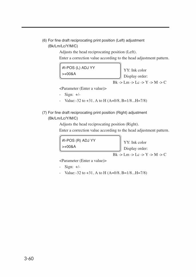
3-60
(6) For fine draft reciprocating print position (Left) adjustment
(Bk/Lm/Lc/Y/M/C)
Adjusts the head reciprocating position (Left).
Enter a correction value according to the head adjustment pattern.
YY: Ink color
Display order:
Bk -> Lm -> Lc -> Y -> M -> C
<Parameter (Enter a value)>
- Sign: +/-
- Value:-32 to +31, A to H (A=0/8, B=1/8...H=7/8)
(7) For fine draft reciprocating print position (Right) adjustment
(Bk/Lm/Lc/Y/M/C)
Adjusts the head reciprocating position (Right).
Enter a correction value according to the head adjustment pattern.
YY: Ink color
Display order:
Bk -> Lm -> Lc -> Y -> M -> C
<Parameter (Enter a value)>
- Sign: +/-
- Value:-32 to +31, A to H (A=0/8, B=1/8...H=7/8)
#I-POS (L) ADJ YY
>+00&A
#I-POS (R) ADJ YY
>+00&A

3-61
Sect
ion
3 O
pera
tion
Pane
l Men
u O
pera
tions
SYSTEM Menu
This menu is used to set or display system parameters.
When the key is pressed, system parameter setting is enabled.
(1) Language for LCD messages (LANGUAGE)
Sets Japanese or English for messages displayed on the LCD.
<Parameter (Enter a choice.)>
- ENGLISH : Displays English messages.
- JAPANESE : Displays Japanese messages.
FUNC SYSTEM
ADJUST RESET
key
#LANGUAGE
>JAPANESE
#LANGUAGE
>ENGLISH
Menu Operations
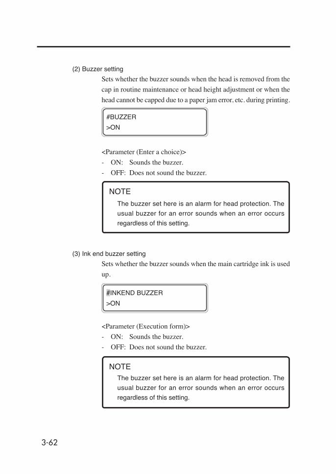
3-62
(2) Buzzer setting
Sets whether the buzzer sounds when the head is removed from the
cap in routine maintenance or head height adjustment or when the
head cannot be capped due to a paper jam error, etc. during printing.
<Parameter (Enter a choice)>
- ON: Sounds the buzzer.
- OFF: Does not sound the buzzer.
The buzzer set here is an alarm for head protection. The
usual buzzer for an error sounds when an error occurs
regardless of this setting.
(3) Ink end buzzer setting
Sets whether the buzzer sounds when the main cartridge ink is used
up.
<Parameter (Execution form)>
- ON: Sounds the buzzer.
- OFF: Does not sound the buzzer.
The buzzer set here is an alarm for head protection. The
usual buzzer for an error sounds when an error occurs
regardless of this setting.
#BUZZER
>ON
#INKEND BUZZER
>ON
NOTE
NOTE
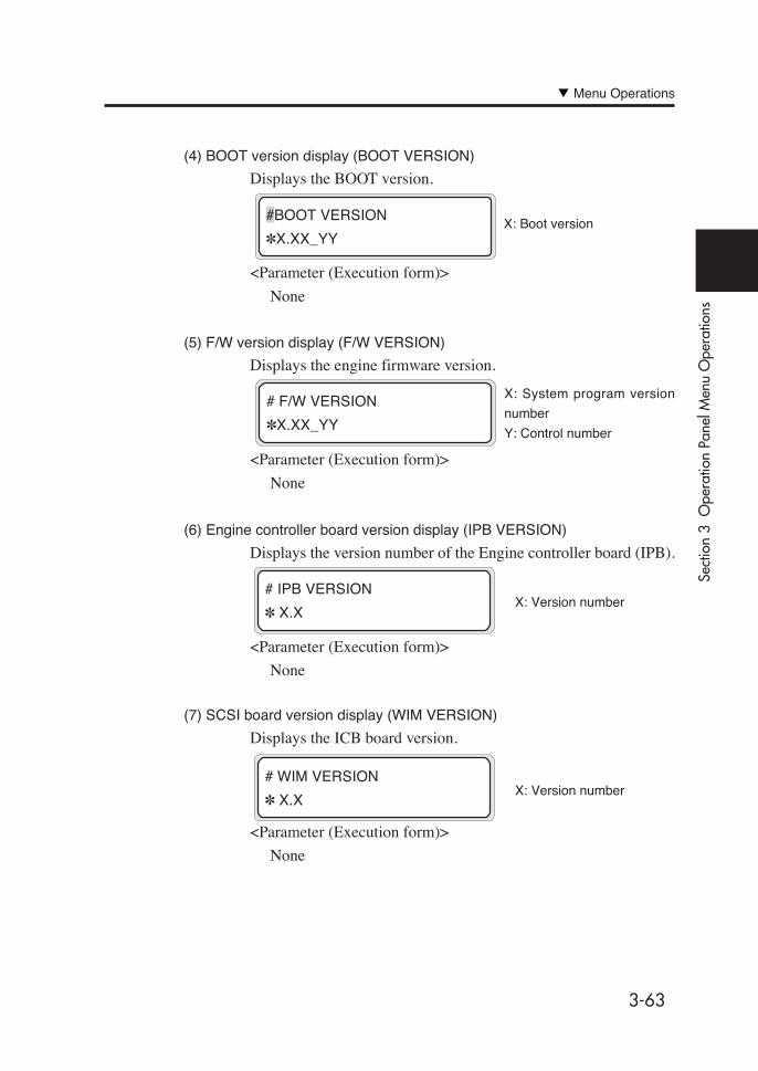
3-63
Sect
ion
3 O
pera
tion
Pane
l Men
u O
pera
tions
(4) BOOT version display (BOOT VERSION)
Displays the BOOT version.
<Parameter (Execution form)>
None
(5) F/W version display (F/W VERSION)
Displays the engine firmware version.
<Parameter (Execution form)>
None
(6) Engine controller board version display (IPB VERSION)
Displays the version number of the Engine controller board (IPB).
<Parameter (Execution form)>
None
(7) SCSI board version display (WIM VERSION)
Displays the ICB board version.
<Parameter (Execution form)>
None
X: Boot version#BOOT VERSION
✽X.XX_YY
X: System program version
number
Y: Control number
# F/W VERSION
✽X.XX_YY
X: Version number# IPB VERSION
✽ X.X
X: Version number# WIM VERSION
✽ X.X
Menu Operations

3-64
(8) ICB board version display (ICB VERSION)
Displays the version number of the ICB board (WIM).
<Parameter (Execution form)>
None
(9) ASIC version display (ASIC VERSION)
Displays the ASIC version.
<Parameter (Execution form)>
None
(10) Heater H/W version display
Displays the heater hardware version.
<Parameter (Execution form)>
None
(11) Heater F/W version display
Displays the heater firmware version.
If the heater cannot be recognized, "--.-" is displayed.
<Parameter (Execution form)>
None
X: Version number#HEART HW VERSION
✽XX.X
X: Version number
X: Version number
#ICB VERSION
✽X.XX
#ASIC VERSION
✽X.XX X: Version number
#HEAT FW VERSION
✽XX.X

3-65
Sect
ion
3 O
pera
tion
Pane
l Men
u O
pera
tions
(12) HEB board version display
Displays the HEB board version.
<Parameter (Execution form)>
None
(13) SCSI ID number display (SCSI ID)
Displays the SCSI ID number set with the rotary switch on the
SCSI board.
<Parameter (Execution form)>
None
(14) System date setting (SYSTEM DATE)
Sets system date used internally in the printer in the order of YY
(year), MM (month), DD (day).
<Parameter (Enter a value)>
00/01/01 to 99/12/31
(15) System time setting (SYSTEM TIME)
Sets system time used internally in the printer.
<Parameter (Enter a value)>
00 : 00 to 23 : 59
#SYSTEM TIME
>00 : 00
#DATE (YY/MM/DD)
>03 / 08 / 01
X: ID number
#SCSI ID
✽ID : X
X: ID number
#HEB VERSION
✽X.X
Menu Operations
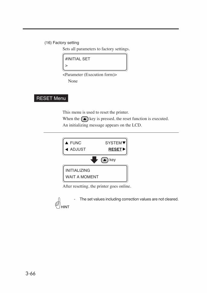
3-66
(16) Factory setting
Sets all parameters to factory settings.
2
<Parameter (Execution form)>
None
RESET Menu
This menu is used to reset the printer.
When the key is pressed, the reset function is executed.
An initializing message appears on the LCD.
After resetting, the printer goes online.
INITIALIZING
WAIT A MOMENT
FUNC SYSTEM
ADJUST RESET
key
- The set values including correction values are not cleared.
HINT
#INITIAL SET
>
4-1
Sect
ion
4 S
peci
al P
rintin
g
Section 4 Special Printing
Special Printing
Double-Sided Printing
Printing on Mesh Tarpaulin
Contents of This Section

4-2
Special Printing
This section explains the details of print modes and gives an out-
line of special printing such as duplex printing.
Print Modes
This printer provides 14 print modes. Choose a print mode according to
the media type, productivity, and image quality. (⇒ See page 3-28)
1. "NORMAL" [Productivity + Image quality oriented] (4-pass)
Standard print mode of this printer. Normally, use this mode. The print resolution is 720×720
dpi. The print speed is 16 m2/h. The image quality is processed at high resolution.
2. "H-QUALITY" [Image quality oriented] (8-pass)
The print resolution is 720×720 dpi, the same as that of NORMAL mode. Use this mode if
media of which drying performance is poor in NORMAL mode are used or if uneven print-
ing is noticeable. The print speed is half the speed of NORMAL mode.
3. "H-DENSITY" [High density printing] (8-pass)
This mode is effective for printing on transparent media such as FF, transparent vinyl chlo-
ride, etc. and when high density is required. A solid image of 100% density is printed at
maximum 200% density. The print speed is the same as that of NORMAL mode.
4. "3 TIMES" [High density printing] (12-pass)
This mode is effective for printing on transparent media such as FF, transparent vinyl chlo-
ride, etc. and when high density is required. Use this mode particularly when you want to
print at higher density than the density of H-DENSITY or H-DENSITY2 mode. In case of
poor drying performance, unidirectional printing will be effective. A solid image of 100%
density is printed at maximum 300% density.
5. "H-QUALITY2" [Image quality oriented] (16-pass)
The print resolution is 720×720 dpi, the same as that of NORMAL mode. Use this mode if
media of which drying performance is poor in H-QUALITY mode are used or if uneven
printing is noticeable. The print speed is half the speed of H-QUALITY mode.
6. "H-DENSITY2" [High density printing] (16-pass)
This mode is effective for printing on transparent media such as FF, transparent vinyl chlo-
ride, etc. and when high density is required. Use this mode if media of which drying perfor-
mance is poor in H-DENSITY mode are used or if uneven printing is noticeable. A solid
image of 100% density is printed at maximum 200% density. The print speed is half the
speed of H-DENSITY mode.

4-3
Sect
ion
4 S
peci
al P
rintin
g
7. "DRAFT" [Productivity oriented] (2-pass)
The print resolution is 360×720 dpi. The print speed is maximum 30 m2/h but the print
density is entirely lighter than that of NORMAL mode, and uneven printing may be notice-
able depending on the type of media. A solid image of 100% density is printed at 50% the
density of NORMAL mode. This mode can also be used for checking the layout.
8. "FAST" [PC processing time reduction] (4-pass)
The density is equivalent to that of NORMAL mode. The print speed is the same as that of
NORMAL mode.
9. "F-H-QUALITY" [PC processing time reduction] (8-pass)
Use this mode if the drying performance is poor in FAST mode or if uneven printing is
noticeable. However, the print speed is half the speed of FAST mode.
10."F-H-DENSITY" [PC processing time reduction + High density printing] (8-pass)
The density and print speed are equivalent to those of H-DENSITY mode.
11. "F-3 TIMES" [PC processing time reduction + High density printing] (12-pass)
The density and print speed are equivalent to those of 3 TIMES mode.
12."F-H-QUAL2" [PC processing time reduction] (16-pass)
Use this mode if the drying performance is poor in F-H-QUALITY mode or if uneven print-
ing is noticeable. The print speed is half the speed of F-H-QUALITY mode.
13."F-H-DENS2" [PC processing time reduction + High density printing] (16-pass)
The density is equivalent to that of H-DENSITY mode. The print speed is half the speed of
F-H-DENSITY mode.
14."FINE DRAFT" [Productivity + Image quality oriented] (4-pass)
The print resolution is 540×720 dpi. The print speed is 20 m2/h, faster than that of NOR-
MAL mode by about 20%. Use this mode if high productivity is required. The image quality
of photographs is almost equivalent to that of NORMAL mode, but a solid image of 100%
density is printed at 75% the density of NORMAL mode. Therefore, if the darkness of
colors is important, use the NORMAL mode.
- The recommended print mode for this printer is "NOR-MAL" mode. Use other modes if productivity and imagequality are important.
- Use the FAST mode in 8 - 13 if the CPU speed of the PC isslow or the memory or HDD capacity is small. These modesput emphasis on the PC processing speed and thus the RIPtime of the PC is shortened, but the input resolution of im-age quality is 360×360 dpi. Accordingly, the printed imagewill be rather rough compared to that of normal modes (1-6).
HINT
Special Printing
4-4
Double sided Printing
Capable of printing on both face and back sides of media.
Mesh Tarpaulin Printing
Capable of printing on a mesh type tarpaulin without a liner.
Textile Printing
Capable of printing on textile media having weak stiffness.
For details, see the User's Guide provided separately.
Dual Roll Print
Capable of printing simultaneously on two media rolls of 50 inches
or less. Simultaneous printing shortens the print time.
For details, see the User's Guide provided separately.

4-5
Sect
ion
4 S
peci
al P
rintin
g
Double-Sided Printing
The following explains the types of double-sided printing and their
procedures.
In the explanation, the surface printed first is referred to as the “front
surface”, and the surface printed second as the “rear surface”.
Types of Double-Sided Printing
The following three types of double-sided printing are available:
- Printing on the back side of media from the take-up unit
(Rear 1)
- Printing on the back side of media from the feeder (Rear
2)
- After rewinding, printing on the back side of media from
the feeder (Rear 2)
- When printing data at a high printing rate, use the optional
liner and sub scroller to prevent media from sticking.
- When a liner is used in printing the rear surface from the
take-up unit (rear 1), one more subscroller is necessary.
Printing on Back Side from Winding unit
After printing on the face side of media, the media is cut and in-
serted again into the feeder through a space at the bottom of the
printer for printing on the back side. (About 2.5 m margin is re-
quired at the top edge of media.)
HINT
Face side printing Back side printing
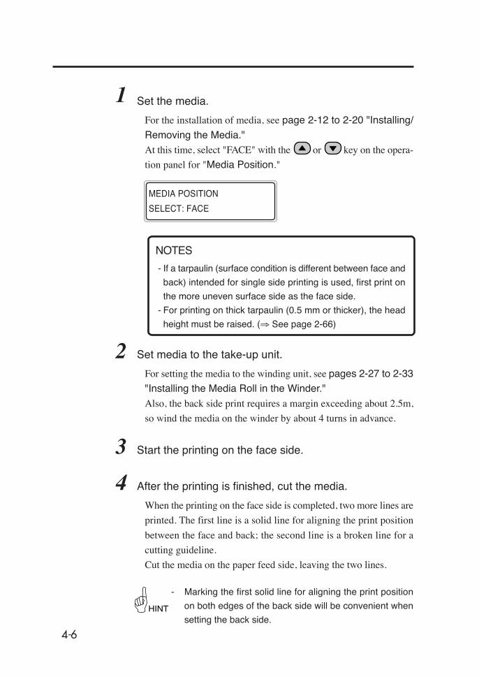
4-6
1 Set the media.
For the installation of media, see page 2-12 to 2-20 "Installing/
Removing the Media."
At this time, select "FACE" with the or key on the opera-
tion panel for "Media Position."
- If a tarpaulin (surface condition is different between face and
back) intended for single side printing is used, first print on
the more uneven surface side as the face side.
- For printing on thick tarpaulin (0.5 mm or thicker), the head
height must be raised. (⇒ See page 2-66)
2 Set media to the take-up unit.
For setting the media to the winding unit, see pages 2-27 to 2-33
"Installing the Media Roll in the Winder."
Also, the back side print requires a margin exceeding about 2.5m,
so wind the media on the winder by about 4 turns in advance.
3 Start the printing on the face side.
4 After the printing is finished, cut the media.
When the printing on the face side is completed, two more lines are
printed. The first line is a solid line for aligning the print position
between the face and back; the second line is a broken line for a
cutting guideline.
Cut the media on the paper feed side, leaving the two lines.
- Marking the first solid line for aligning the print position
on both edges of the back side will be convenient when
setting the back side.
MEDIA POSITION
SELECT: FACE
HINT
NOTES
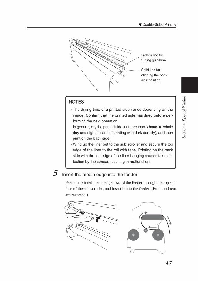
4-7
Sect
ion
4 S
peci
al P
rintin
g
Double-Sided Printing
- The drying time of a printed side varies depending on the
image. Confirm that the printed side has dried before per-
forming the next operation.
In general, dry the printed side for more than 3 hours (a whole
day and night in case of printing with dark density), and then
print on the back side.
- Wind up the liner set to the sub scroller and secure the top
edge of the liner to the roll with tape. Printing on the back
side with the top edge of the liner hanging causes false de-
tection by the sensor, resulting in malfunction.
5 Insert the media edge into the feeder.
Feed the printed media edge toward the feeder through the top sur-
face of the sub scroller, and insert it into the feeder. (Front and rear
are reversed.)
Broken line for
cutting guideline
Solid line for
aligning the back
side position
NOTES

4-8
6 Adjust the media so that the solid line for aligning the
print position comes to the platen groove position.
If the solid line does not align with the platen
groove between the left and right sides, align
either side first, and while holding this side in
place, pull the other side to adjust the
position.
- When printing on the back side using a liner, if the solid
line for aligning the print position does not come to the
platen groove, move the media such that it slides on the
liner to align over the whole width. At this time, be sure to
align the right edges of the liner and media.
For setting the liner, see page 4-25.
7 Push the pressure roller up/down lever down.
Pressure roller up/
down lever
Platen groove
HINT
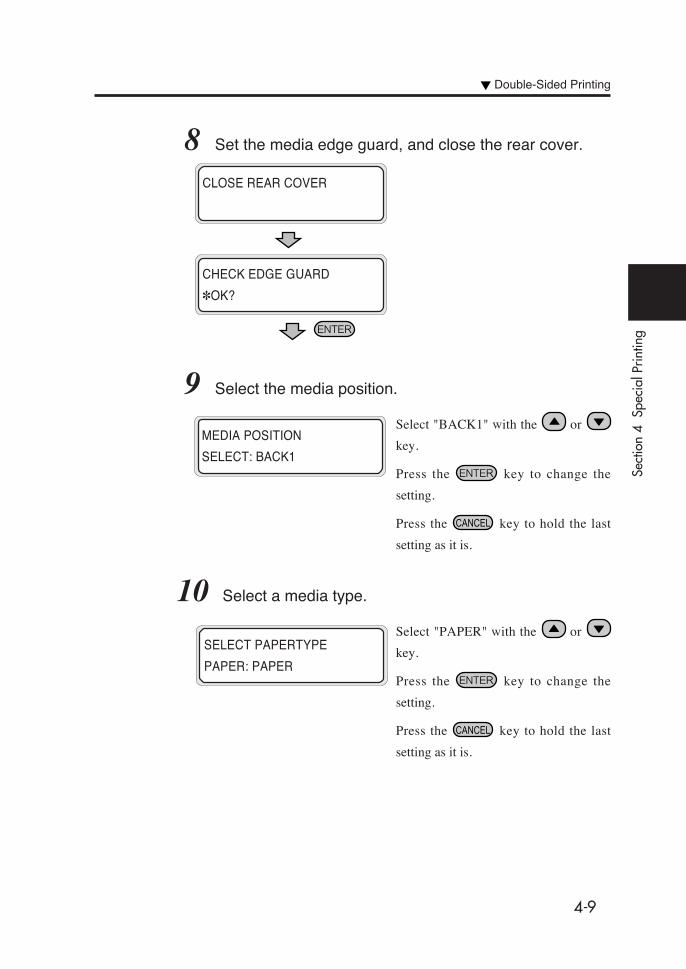
4-9
Sect
ion
4 S
peci
al P
rintin
g
8 Set the media edge guard, and close the rear cover.
9 Select the media position.
Select "BACK1" with the or
key.
Press the key to change the
setting.
Press the key to hold the last
setting as it is.
10 Select a media type.
Select "PAPER" with the or
key.
Press the key to change the
setting.
Press the key to hold the last
setting as it is.
CLOSE REAR COVER
CHECK EDGE GUARD
✽OK?
MEDIA POSITION
SELECT: BACK1
SELECT PAPERTYPE
PAPER: PAPER
Double-Sided Printing

4-10
11 Select whether a liner is used or not.
Select whether a liner is used or not with
the or key.
If a liner is used, see page 4-25.
Press the key to change the
setting.
Press the key to hold the last
setting as it is.
12 Slacken the media and install the tension bar using the
feed switch.
- The next operation will not start if the
media slack is inadequate.
13 Media setting operation will start automatically.
- If the operation terminates normally, the
printer returns to the online or offline
state.
- If it terminates unsuccessfully, an error
message will be displayed.
Return to step 4 for retry.
CHECK BUFFER
✽OK?
Tension bar
LINER
SELECT: NOT USE
PREPARING PAPER
WAIT A MOMENT

4-11
Sect
ion
4 S
peci
al P
rintin
g
- Before starting the printing on the back side, change the
"VACUUM" and "PEEL MODE" settings from the operation
panel according to the media used.
For sticky media, set the “VACUUM” to “LOW” and the “PEEL
MODE” to “ON”.
- It is recommended that the head be cleaned before start-
ing the printing on the back side.
14 Print on the back side.
- The data from the RIP are transferred in 180° rotated state
on the face and back.
HINT
NOTE
NOTE
Double-Sided Printing

4-12
Printing on Back Side from Paper Feeder
After printing on the face side, the main scroller to which the me-
dia was wound is set in the feeder, and printing on the back side is
performed.
1 Set the media.
For the installation of media, see P.2-12 to 2-20 "Installing/Re-
moving the Media."
At this time, select "FACE" with the or key on the opera-
tion panel for "Media Position."
- If a tarpaulin (surface condition is different between face and
back) intended for single side printing is used, first print on
the more uneven surface side as a face side.
- If printing on thick tarpaulin (0.5 mm or thicker), the head
height must be raised. (⇒ See page 2-66)
Face side printing Back side printing
relocation
MEDIA POSITION
SELECT: FACE
Main scroller relocation
NOTES

4-13
Sect
ion
4 S
peci
al P
rintin
g
2 Set media to the take-up unit.
For setting the media to the take-up unit, see pages 2-27 to 2-33"Installing the Media Roll in the Winder."
3 Start the printing on the face side.
4 After the printing is finished, cut the media.
When the printing on the face side is completed, two more lines areprinted. The first line is a solid line for aligning the print positionbetween face and back, and the second line is a broken line for acutting guideline.Cut the media on the feed side, leaving two lines.
- Marking the first solid line for aligning the print positionon both edges of the back side will be convenient whensetting the back side.
- The drying time of the printed side varies depending on theimage. Confirm that the printed side has dried before per-forming the next operation.In general, dry the printed side for more than 3 hours (a wholeday and night in case of printing with dark density), and thenprint on the back side.
- Wind up the liner set on the sub scroller and secure the topedge of the liner to the roll with tape. Printing on the backside with the top edge of the liner hanging causes false de-tection by the sensor, resulting in malfunction.
HINT
Broken line for a cutting
guideline
Solid line for aligning
the back side position
NOTES
Double-Sided Printing

4-14
5 Remove the scroller on the feed side from the printer.
6 Remove the scroller on the media discharge side from
the printer, and install it on the feed side.
- Use the recommended cart with care when removing and
installing the scroller.
7 Lift the pressure roller up/down lever.
Recommended
cart
Pressure roller up/
down lever
NOTE

4-15
Sect
ion
4 S
peci
al P
rintin
g
8 Set the feed direction switch again.
9 Slacken the media using the Feed switch and insert the
media edge into the feeder.
Insert the media into the feeder while
stretching the media with your hands to
prevent wrinkle.
If the media curls and is hard to insert into the
paper feeder, use a liner and insert the media
top edge under the liner to feed the media.
- Inserting the media obliquely or inserting wrinkled media
causes a paper jam or skewed feed.
Feed direction switch
Winder switch (white)
Feed switch (green)
■ Feed direction switch, Winder switch, Feed switch
↑ Inner take-up
↓ Outer take-up
NOTE
Double-Sided Printing
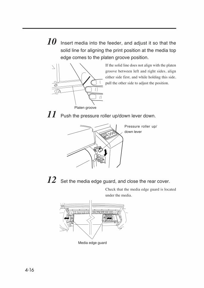
4-16
10 Insert media into the feeder, and adjust it so that the
solid line for aligning the print position at the media top
edge comes to the platen groove position.
If the solid line does not align with the platen
groove between left and right sides, align
either side first, and while holding this side,
pull the other side to adjust the position.
11 Push the pressure roller up/down lever down.
12 Set the media edge guard, and close the rear cover.
Check that the media edge guard is located
under the media.
Pressure roller up/
down lever
Media edge guard
Platen groove
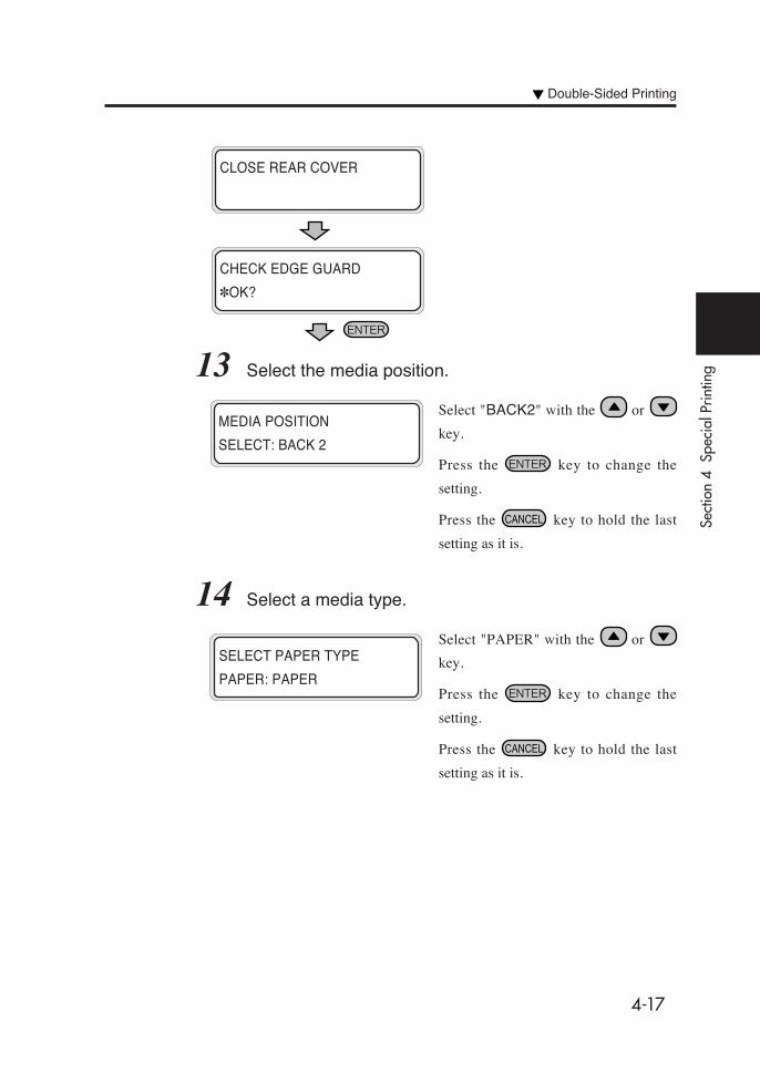
4-17
Sect
ion
4 S
peci
al P
rintin
g13 Select the media position.
Select "BACK2" with the or
key.
Press the key to change the
setting.
Press the key to hold the last
setting as it is.
14 Select a media type.
Select "PAPER" with the or
key.
Press the key to change the
setting.
Press the key to hold the last
setting as it is.
CLOSE REAR COVER
CHECK EDGE GUARD
✽OK?
MEDIA POSITION
SELECT: BACK 2
SELECT PAPER TYPE
PAPER: PAPER
Double-Sided Printing
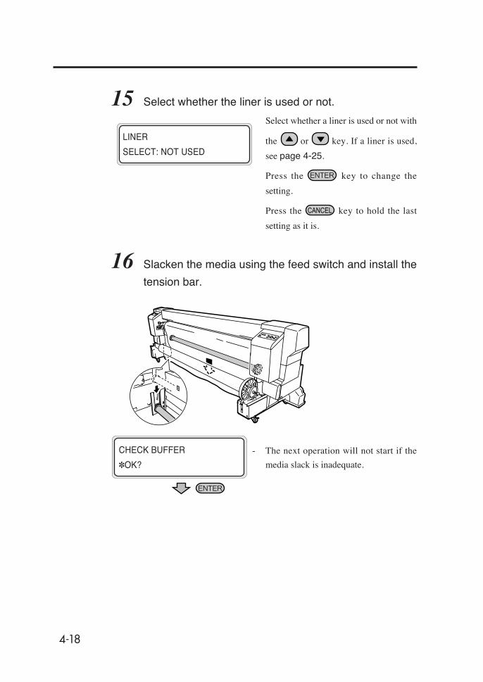
4-18
15 Select whether the liner is used or not.
Select whether a liner is used or not with
the or key. If a liner is used,
see page 4-25.
Press the key to change the
setting.
Press the key to hold the last
setting as it is.
16 Slacken the media using the feed switch and install the
tension bar.
- The next operation will not start if the
media slack is inadequate.
LINER
SELECT: NOT USED
CHECK BUFFER
✽OK?

4-19
Sect
ion
4 S
peci
al P
rintin
g
17 Media setting operation will start automatically.
- If the operation terminates normally, the
printer returns to the online or offline
state.
- If it terminates unsuccessfully, an error
message will be displayed.
Return to step 4 for retry.
- Before starting the printing on the back side, change the set-
tings of "VACUUM" and "PEEL MODE" from the operation
panel according to the media used.
For sticky media, set "VACUUM" to "LOW" and "PEEL
MODE" to "ON".
- It is recommended that the head be cleaned before start-
ing the printing on the back side.
18 Print on the back side.
- The data from the RIP are transferred in 180° rotated state
between face and back.
PREPARING PAPER
WAIT A MOMENT
HINT
NOTE
NOTE
Double-Sided Printing
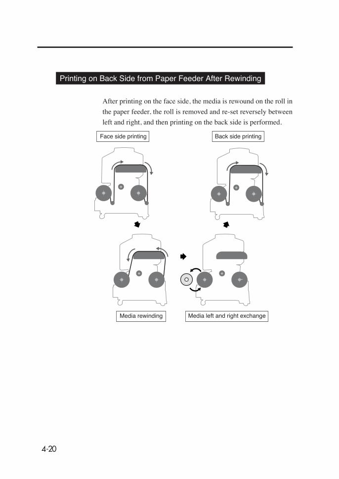
4-20
Printing on Back Side from Paper Feeder After Rewinding
After printing on the face side, the media is rewound on the roll in
the paper feeder, the roll is removed and re-set reversely between
left and right, and then printing on the back side is performed.
Face side printing Back side printing
Media left and right exchangeMedia rewinding
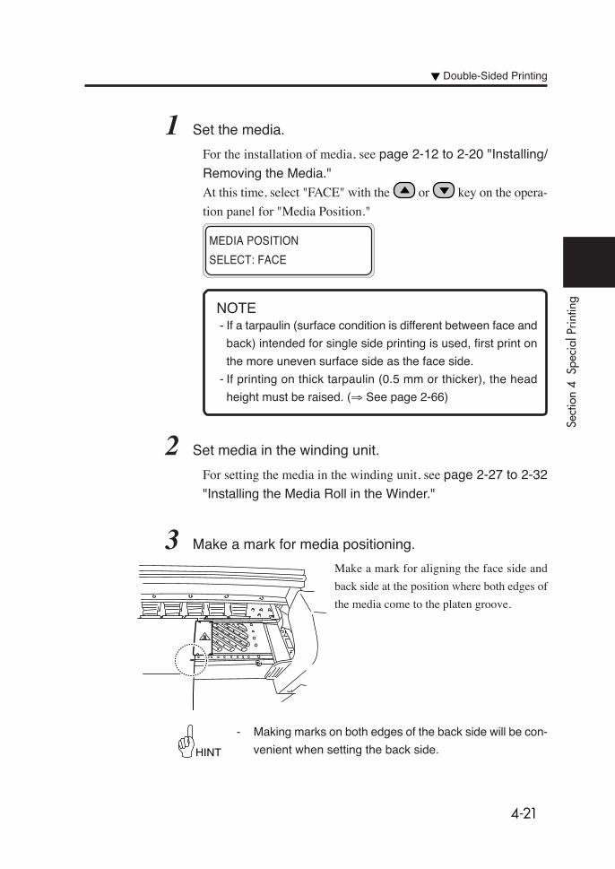
4-21
Sect
ion
4 S
peci
al P
rintin
g
HINT
1 Set the media.
For the installation of media, see page 2-12 to 2-20 "Installing/
Removing the Media."
At this time, select "FACE" with the or key on the opera-
tion panel for "Media Position."
- If a tarpaulin (surface condition is different between face and
back) intended for single side printing is used, first print on
the more uneven surface side as the face side.
- If printing on thick tarpaulin (0.5 mm or thicker), the head
height must be raised. (⇒ See page 2-66)
2 Set media in the winding unit.
For setting the media in the winding unit, see page 2-27 to 2-32
"Installing the Media Roll in the Winder."
3 Make a mark for media positioning.
Make a mark for aligning the face side and
back side at the position where both edges of
the media come to the platen groove.
- Making marks on both edges of the back side will be con-
venient when setting the back side.
MEDIA POSITION
SELECT: FACE
NOTE
Double-Sided Printing

4-22
4 Start printing on the face side.
5 After printing is finished, remove the tension bars on both
the feed side and paper outlet side, and lift the pressure
roller up/down lever.
6 Rewind the media on the main scroller in the feeder.
Press the winder switch on the feed side and the feed switch on the paper
outlet side simultaneously to rewind the media.
- The printed side drying time varies depending on the image.
Confirm that the printed side has dried before performing
the next operation.
In general, dry the printed side for more than 3 hours (a whole
day and night in case of printing with dark density), and then
print on the back side.
- Avoid uneven take-up when rewinding the media.
Pressure roller up/
down lever
NOTES

4-23
Sect
ion
4 S
peci
al P
rintin
g
7 Remove the media roll including the scroller.
- Use the recommended cart with care when removing and
installing the scroller.
8 Remove the media from the main scroller, exchange the
media between left and right, and reinsert the media into
the main scroller.
9 Install a media roll attached with the main scroller on the
printer, aligning with the roll slot.
Recommendedcart
NOTE
Double-Sided Printing

4-24
10 Adjust the media so that the mark on the media made in
step 3 comes to the groove in the platen.
The operation after step 10 is same as that in step 7 and subse-
quent steps in "■ Printing on Back Side from Feeder." See page
4-14.
- The data transferred from RIP need not be rotated.
NOTE

4-25
Sect
ion
4 S
peci
al P
rintin
g
Using the Liner
Printing on the back side may require a liner to be used depending
on the media type. Also, use a liner when printing on the back side
if printing of dark density was performed on the face side.
- Confirm the vertical scale in advance because the vertical
scale is different if the liner is used.
- The liner wrinkles easily, and therefore if the liner is wound
on the winder, it is recommended that only the liner be wound,
not the printed media.
The following explanation assumes that the printing on the face
side has been completed.
1 Insert a liner roll into the sub scroller.
Confirm the take-up direction of media, and
insert the sub scroller into the liner roll.
2 Lock the flange on the left side.
Insert the left flange into the shaft, and rotate
the knob clockwise to lock the left flange.
Sub scroller
The flange on the right side is secured to the
sub scroller. When setting the sub scroller in
the printer, this side comes to the right.
Left flange
(In case of outer take-up)
NOTE
Double-Sided Printing
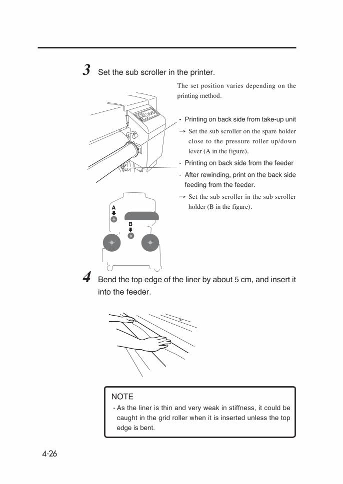
4-26
3 Set the sub scroller in the printer.
The set position varies depending on the
printing method.
- Printing on back side from take-up unit
→ Set the sub scroller on the spare holder
close to the pressure roller up/down
lever (A in the figure).
- Printing on back side from the feeder
- After rewinding, print on the back side
feeding from the feeder.
→ Set the sub scroller in the sub scroller
holder (B in the figure).
4 Bend the top edge of the liner by about 5 cm, and insert it
into the feeder.
- As the liner is thin and very weak in stiffness, it could be
caught in the grid roller when it is inserted unless the top
edge is bent.
A
B
NOTE
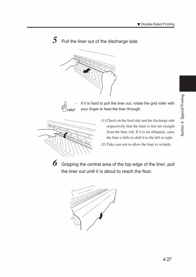
4-27
Sect
ion
4 S
peci
al P
rintin
g
5 Pull the liner out of the discharge side.
- If it is hard to pull the liner out, rotate the grid roller with
your finger to feed the liner through.
(1) Check on the feed side and the discharge side
respectively that the liner is fed out straight
from the liner roll. If it is set obliquely, raise
the liner a little to shift it to the left or right.
(2) Take care not to allow the liner to wrinkle.
6 Gripping the central area of the top edge of the liner, pull
the liner out until it is about to reach the floor.
HINT
Double-Sided Printing
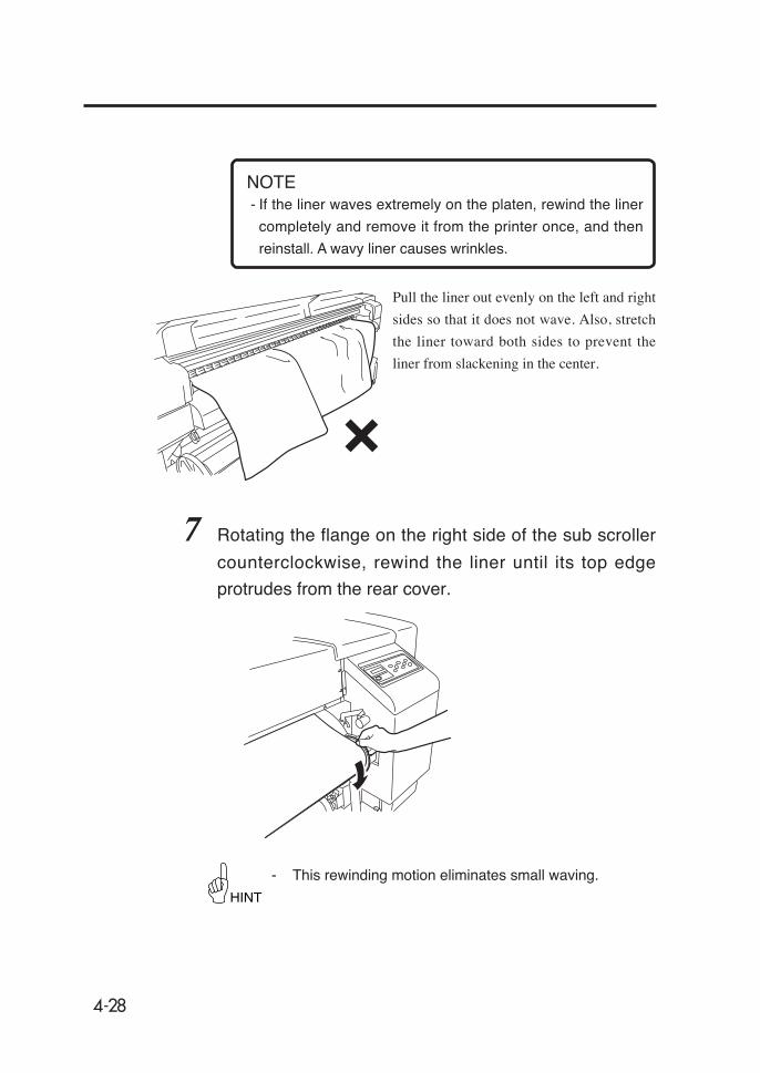
4-28
- If the liner waves extremely on the platen, rewind the liner
completely and remove it from the printer once, and then
reinstall. A wavy liner causes wrinkles.
Pull the liner out evenly on the left and right
sides so that it does not wave. Also, stretch
the liner toward both sides to prevent the
liner from slackening in the center.
7 Rotating the flange on the right side of the sub scroller
counterclockwise, rewind the liner until its top edge
protrudes from the rear cover.
- This rewinding motion eliminates small waving.
HINT
NOTE

4-29
Sect
ion
4 S
peci
al P
rintin
g
8 Pull the liner out to the position where the liner can be
secured to the winder with tapes.
9 Push the pressure roller up/down lever down.
10 With the liner stretched, secure it to the winder with
tapes.
Confirm the take-up direction, and secure the
liner in the center first, and then both edges
with the tapes.
- In "printing on the back side from the take-up unit", the liner
cannot be wound on the winder.
Pressure roller up/
down lever
Tapes
NOTE
Double-Sided Printing
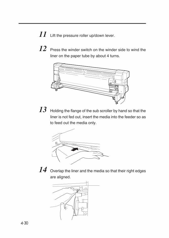
4-30
11 Lift the pressure roller up/down lever.
12 Press the winder switch on the winder side to wind the
liner on the paper tube by about 4 turns.
13 Holding the flange of the sub scroller by hand so that the
liner is not fed out, insert the media into the feeder so as
to feed out the media only.
14 Overlap the liner and the media so that their right edges
are aligned.

4-31
Sect
ion
4 S
peci
al P
rintin
g
15 Adjust the media so that the solid line for aligning the
print position at the media top edge comes to the platen
groove position.
If the solid line does not align with the platen
groove between left and right sides, align
either side first, and while holding this side,
pull the other side to adjust the position of the
media only.
16 Push the pressure roller up/down lever down.
17 Set the media edge guard, and close the rear cover.
Check if the media edge guard is located
under the media.
Platen groove
Media edge guard
Double-Sided Printing

4-32
18 Select the media position.
Select "BACK1" or "BACK2" with the
or key.
"BACK1":
- Printing on back side from take-up unit
"BACK2":
- Printing on back side from paper feeder
- After rewinding, printing on back side
from paper feeder
Press the key to change the
setting.
Press the key to hold the last
setting as it is.
19 Select a media type.
Select "PAPER" with the or
key.
Press the key to change the
setting.
Press the key to hold the last
setting as it is.
CLOSE REAR COVER
CHECK EDGE GUARD
✽OK?
MEDIA POSITION
SELECT: BACK 1
SELECT PAPER TYPE
PAPER: PAPER
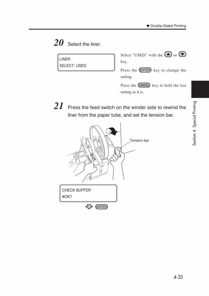
4-33
Sect
ion
4 S
peci
al P
rintin
g
20 Select the liner.
Select "USED" with the or
key.
Press the key to change the
setting.
Press the key to hold the last
setting as it is.
21 Press the feed switch on the winder side to rewind the
liner from the paper tube, and set the tension bar.
LINER
SELECT: USED
CHECK BUFFER
✽OK?
Tension bar
Double-Sided Printing
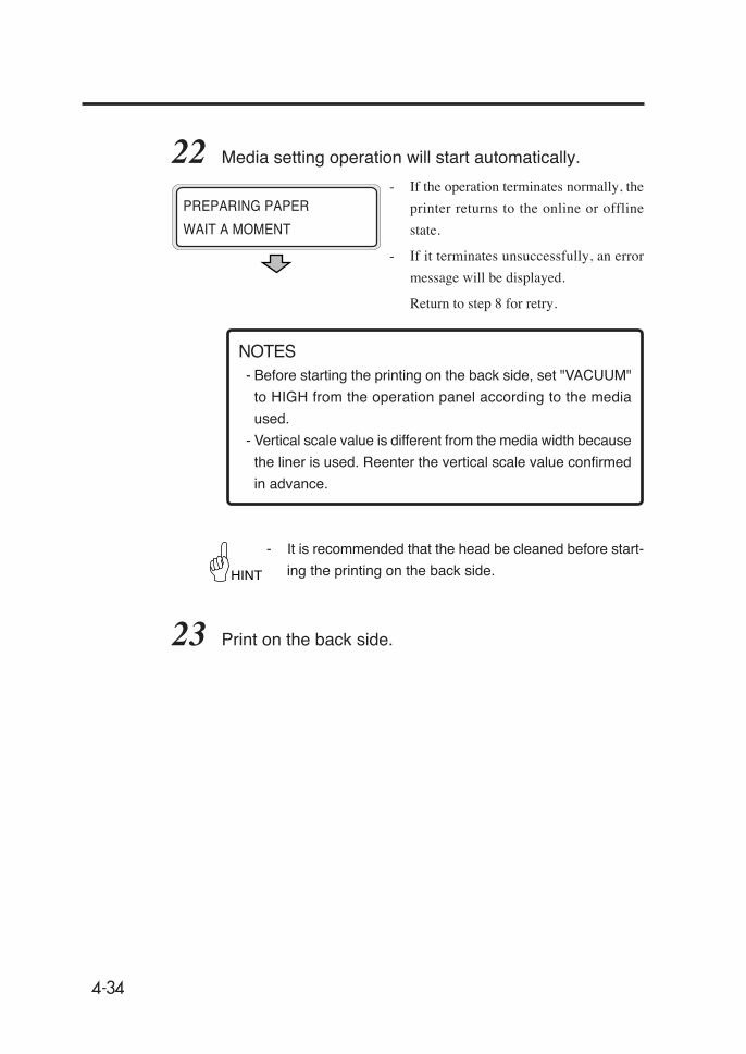
4-34
HINT
22 Media setting operation will start automatically.
- If the operation terminates normally, the
printer returns to the online or offline
state.
- If it terminates unsuccessfully, an error
message will be displayed.
Return to step 8 for retry.
- Before starting the printing on the back side, set "VACUUM"
to HIGH from the operation panel according to the media
used.
- Vertical scale value is different from the media width because
the liner is used. Reenter the vertical scale value confirmed
in advance.
- It is recommended that the head be cleaned before start-
ing the printing on the back side.
23 Print on the back side.
PREPARING PAPER
WAIT A MOMENT
NOTES
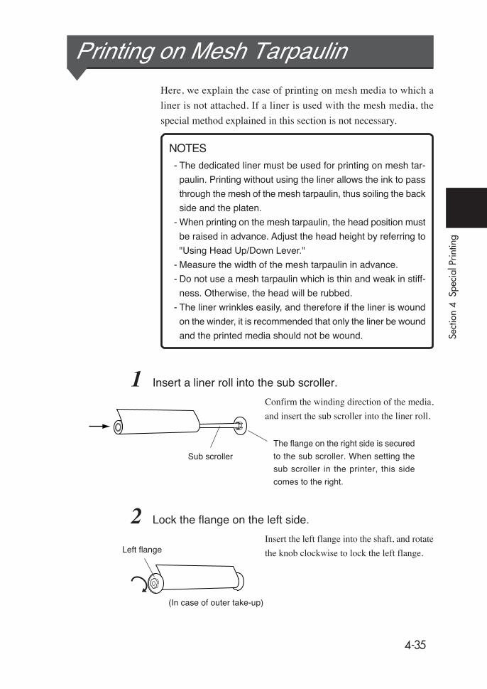
4-35
Sect
ion
4 S
peci
al P
rintin
g
Printing on Mesh TarpaulinHere, we explain the case of printing on mesh media to which a
liner is not attached. If a liner is used with the mesh media, the
special method explained in this section is not necessary.
- The dedicated liner must be used for printing on mesh tar-
paulin. Printing without using the liner allows the ink to pass
through the mesh of the mesh tarpaulin, thus soiling the back
side and the platen.
- When printing on the mesh tarpaulin, the head position must
be raised in advance. Adjust the head height by referring to
"Using Head Up/Down Lever."
- Measure the width of the mesh tarpaulin in advance.
- Do not use a mesh tarpaulin which is thin and weak in stiff-
ness. Otherwise, the head will be rubbed.
- The liner wrinkles easily, and therefore if the liner is wound
on the winder, it is recommended that only the liner be wound
and the printed media should not be wound.
1 Insert a liner roll into the sub scroller.
Confirm the winding direction of the media,
and insert the sub scroller into the liner roll.
2 Lock the flange on the left side.
Insert the left flange into the shaft, and rotate
the knob clockwise to lock the left flange.
Sub scroller
The flange on the right side is secured
to the sub scroller. When setting the
sub scroller in the printer, this side
comes to the right.
Left flange
(In case of outer take-up)
NOTES

4-36
3 Set the sub scroller in the printer.
4 Bend the top edge of the liner by about 5 cm.
- As the liner is thin and very weak in stiffness, it could be
caught in the grid roller when it is inserted unless the top
edge is bent.
Sub scroller holder
NOTE

4-37
Sect
ion
4 S
peci
al P
rintin
g
5 Insert the liner and pull the liner out of the discharge side.
- If it is hard to pull the liner out, rotate the grid roller with
your finger to feed the liner through.
(1) Check on the feed side and the discharge side
respectively that the liner is fed out straight
from the liner roll. If it is set obliquely, raise
the liner a little to shift it to the left or right.
(2) Take care not to allow the liner to wrinkle.
6 Gripping the central area of the top edge of the liner, pull
the liner out until it is about to reach the floor.
HINT
Printing on Mesh Tarpaulin

4-38
- If the liner waves extremely on the platen, rewind the liner
completely and remove it from the printer once, and then
reinstall. A wavy liner causes wrinkles.
Pull the liner out evenly on the left and right
sides so that it does not wave. Also, stretch
the liner toward both sides to prevent the
liner from slackening in the center.
7 Rotating the flange on the right side of the sub scroller
counterclockwise, rewind the liner until its top edge
protrudes from the rear cover.
- This rewinding motion eliminates small waving.
HINT
NOTE
Sub scroller
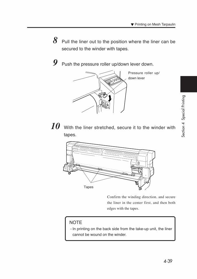
4-39
Sect
ion
4 S
peci
al P
rintin
g
8 Pull the liner out to the position where the liner can be
secured to the winder with tapes.
9 Push the pressure roller up/down lever down.
10 With the liner stretched, secure it to the winder with
tapes.
Confirm the winding direction, and secure
the liner in the center first, and then both
edges with the tapes.
- In printing on the back side from the take-up unit, the liner
cannot be wound on the winder.
Pressure roller up/
down lever
Tapes
NOTE
Printing on Mesh Tarpaulin

4-40
11 Lift the pressure roller up/down lever.
12 Press the winder switch on the winder side to wind the
liner on the paper tube by about 4 turns.
13 Set a mesh tarpaulin roll.
For installation of a mesh tarpaulin roll, see Section 2 Basic Opera-
tions (⇒ See page 2-12 to 2-15).
14 Holding the flange of the sub scroller by hand so that the
liner is not fed out, insert the mesh tarpaulin into the
paper feeder so that only the mesh tarpaulin is fed out.
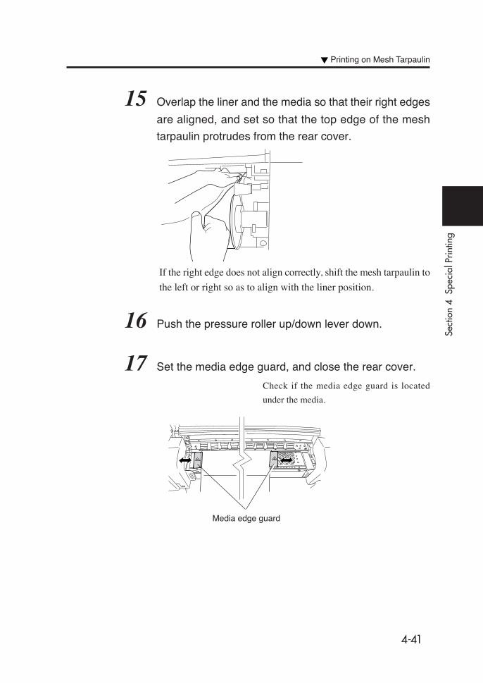
4-41
Sect
ion
4 S
peci
al P
rintin
g
15 Overlap the liner and the media so that their right edges
are aligned, and set so that the top edge of the mesh
tarpaulin protrudes from the rear cover.
If the right edge does not align correctly, shift the mesh tarpaulin to
the left or right so as to align with the liner position.
16 Push the pressure roller up/down lever down.
17 Set the media edge guard, and close the rear cover.
Check if the media edge guard is located
under the media.
Media edge guard
Printing on Mesh Tarpaulin

4-42
18 Select the media position.
Select "MAIN" with the or
key.
Press the key to change the
setting.
Press the key to hold the last
setting as it is.
19 Select the media type.
Select "PAPER" with the or
key.
Press the key to change the
setting.
Press the key to hold the last
setting as it is.
If the mesh tarpaulin has not been registered in advance, enter it
newly. For details of the entry method, see Section 3 "ENTRY
Menu."
MEDIA POSITION
SELECT: MAIN
CLOSE REAR COVER
CHECK EDGE GUARD
✽OK?
SELECT PAPER TYPE
PAPER: PAPER

4-43
Sect
ion
4 S
peci
al P
rintin
g
- If the mesh tarpaulin is narrower than the liner, set "DETECT
WIDTH" to "MANUAL1" in the ENTRY menu. Selecting
"AUTO" allows the printer to recognize the liner width as the
mesh tarpaulin width and to print the data at the right edge
on the liner.
The contents set with the ENTRY menu are as follows:
DETECT WIDTH → MANUAL1
SIZE → Enter the mesh tarpaulin width
SIZE2 → Enter the liner width
20 Select the liner.
Select "USED" with the or
key.
Press the key to change the
setting.
Press the key to hold the last
setting as it is.
21 Press the feed switch to slacken the mesh tarpaulin and
install the tension bar.
LINER
SELECT: USED
Tension bar
NOTE
Printing on Mesh Tarpaulin

4-44
- The next operation will not start if the
media slack is inadequate.
22 Media setting operation will start automatically.
- If the operation terminates normally, the
printer returns to the online or offline
state.
- If it terminates unsuccessfully, an error
message will be displayed.
Return to step 13 for retry.
PREPARING PAPER
WAIT A MOMENT
CHECK BUFFER
✽OK?
5-1
Sect
ion
5 H
eate
r C
ontro
ller
Men
u O
pera
tion
Section 5 Heater Controller Menu Operation
This section describes heater controller temperature control, LCD
displays, parameter setup mode operations, and error messages.
Temperature Control
LCD Display
Parameter Setup Mode
Error Messages
Contents of This Section

5-2
Temperature ControlThe following are the three states of heater control:
(1) Maintaining a preset temperature
Function: To heat the media for reduction of ink drying time,
improvement of ink fixing, and media winkle
prevention.
Status: Each heater temperature is maintained at the pre-
set temperature on the heater control panel.
Conditions: (1) The heater ON/OFF setting on the heater
control panel is set to ON and a print start
command is received.
(2) Under condition (1) above, the specified de-
lay time has elapsed after the print end com-
mand was received.
(2) Maintaining the heater at standby temperature
Function: To shorten the time to reach the preset temperature
at print start.
Status: The heater temperature is maintained at the speci-
fied standby temperature (35 °C) for all heaters.
When the preset temperature is lower than the
specified standby temperature (35 °C), the printer
maintains the preset temperature.
Condition: The specified standby time has elapsed after
completion of the preset temperature maintaining
condition.

5-3
Sect
ion
5 H
eate
r C
ontro
ller
Men
u O
pera
tion
Temperature Control
(3) Temperature Control Stop Condition
Function: To prevent useless current consumption, to protect
the media from being damaged due to heating by
heaters, and to protect the user from being burned
by touching the heaters when printing is not being
performed.
Status: The ambient temperature is reached slowly.
Condition: The printer is neither in preset temperature main-
taining status nor in standby temperature maintain-
ing status.Start of heating
End of heating
Start of print
End of print
Printer heater preset temperature
Rear heater preset temperature
Front heater preset temperature
Standby temperature
Environmental temperature
Maintaining the preset temperature
Maintaining thestand by temperature
Maintaining the preset temperature
Maintaining thestand by temperature
Stop of temperature control
PrintPrint
Delaytime
settingvalue
Delaytime
settingvalue
Standby settingtime
Standby settingtime
(Time)
(Temperature)
Start of heating: The print start command is received and heating
starts. (The print operation does not start until the
heaters reach the preset temperature. However, if
"WAIT HEATER" is set to "SKIP", print opera-
tion starts even though the heaters do not reach
the preset temperature.)
Start of printing: The heaters reach the preset temperature and print-
ing starts.
End of printing: A print end command is received and printing
ends.

5-4
HeaterSetup
temperatureCurrent
temperature
FRONT AAA XXX
PRINT BBB YYY
REA CCC ZZZ
C Celsius
F Fahrenheit
Preset temperature
Current temperature
LCD Display(1) Display in normal mode
Display: (AAA to CCC, YYY to ZZZ) Temperature unit: (U)
• Preset temperature display
When using a Fahrenheit display, the temperature is displayed
to three digits.
(99˚ Fahrenheit or less temperature is displayed with a space
plus 2 digits.)
• Display renewal period
The temperature is measured every 5 seconds and the display is
renewed.
(2) Display at heater ON
When each heater is heated, “+” is displayed in place of the unit of
each heater current temperature on the second line. The unit display is
restored at the completion of heating. In the display example shown
above, the front heater is heated.
AAAU BBBU CCCU
XXX+ YYYU ZZZU
Heater ON
AAAU BBBU CCCU
XXXU YYYU ZZZU
Front heater Printer heater Rear heater

5-5
Sect
ion
5 H
eate
r C
ontro
ller
Men
u O
pera
tion
(3) Display at heater OFF
“OFF” is displayed in three digits in the setup temperature area of
the heater turned OFF on line 1.
The temperature unit of the heater turned OFF is not displayed.
The current temperature area is displayed as it is on line 2.
(4) Display when heater AC power is turned OFF
“TURN ON HEATER POWER SWITCH” massage is displayed
on the LCD.
OFF BBBU CCCU
XXXU YYYU ZZZU
LCD Display
TURN ON HEATER
POWER SWITCH
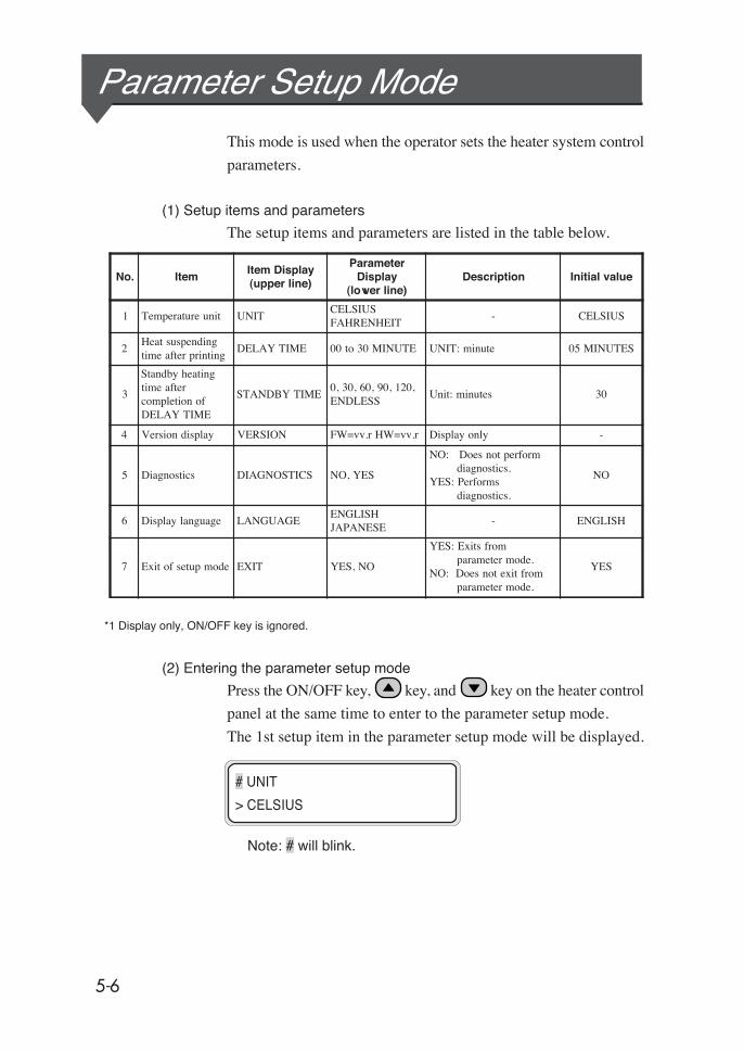
5-6
Parameter Setup ModeThis mode is used when the operator sets the heater system control
parameters.
(1) Setup items and parameters
The setup items and parameters are listed in the table below.
*1 Display only, ON/OFF key is ignored.
(2) Entering the parameter setup mode
Press the ON/OFF key, key, and key on the heater control
panel at the same time to enter to the parameter setup mode.
The 1st setup item in the parameter setup mode will be displayed.
Note: # will blink.
# UNIT
> CELSIUS
No. ItemItem Display(upper line)
ParameterDisplay
(lower line)Description Initial value
1 Temperature unit UNITCELSIUSFAHRENHEIT
- CELSIUS
2Heat suspendingtime after printing
DELAY TIME 00 to 30 MINUTE UNIT: minute 05 MINUTES
3
Standby heatingtime aftercompletion ofDELAY TIME
STANDBY TIME0, 30, 60, 90, 120,ENDLESS
Unit: minutes 30
4 Version display VERSION FW=vv.r HW=vv.r Display only -
5 Diagnostics DIAGNOSTICS NO, YES
NO: Does not performdiagnostics.
YES: Performsdiagnostics.
NO
6 Display language LANGUAGEENGLISHJAPANESE
- ENGLISH
7 Exit of setup mode EXIT YES, NO
YES: Exits fromparameter mode.
NO: Does not exit fromparameter mode.
YES

5-7
Sect
ion
5 H
eate
r C
ontro
ller
Men
u O
pera
tion
(3) Moving among the setup items
Select the desired setup item with the and keys on the
heater control panel.
Press the key on the heater control panel to move to the next
(lower) setup item on the “(1) Parameter Setting Mode Parameter
List”. When the lowest setup item is already selected, the selection
returns to the highest setup item.
Press the key on the front heater to move to the
next higher item on the “(1) Parameter Setting Mode Parameter
List.” When the highest item is already selected, the selection re-
turns to the lowest item.
(4) Selecting the setup item
When the setup item for which you want to set a parameter is dis-
played, press the ON/OFF key on the heater control panel to enter
the setup item.
(Example) Temperature unit setting.
Note: - # will be returned to normal display.
- ✽ blinks.
(5) Selecting a setting value
Select a setting value with the and keys on the heatercontrol panel.Press the key on the heater control panel temperature unit set-ting screen.
Note: - ✽ blinks
Press the key on the heater control panel to move to the previ-ous (upper) setup item.Press the key on the heater control panel to move to the next(lower) setup item.
# UNIT
✽ FAHRENHEIT
Parameter Setup Mode
# UNIT
✽ CELSIUS

5-8
(6) Finalizing the setting.
Display the desired setting on the 2nd line.
Press the ON/OFF key on the heater control panel to finalize the
setting.
The display returns to the setup item setting screen.
Note: - # blinks
When a setting which is not desired is displayed on the 2nd line,
press the ON/OFF key on the heater control panel to cancel that
setting and return to the setup item selection screen.
(7) Exiting from parameter setting mode
Move to the last setup item, EXIT menu.
Note: - # blinks
Press the ON/OFF key on the heater control panel.
Note: - ✽ blinks
Press the ON/OFF key on the heater control panel.
# UNIT
✽ FAHRENHEIT
# EXIT
✽ YES
# EXIT
✽ YES
AAAU BBBU CCCU
XXXU YYYU ZZZU

5-9
Sect
ion
5 H
eate
r C
ontro
ller
Men
u O
pera
tion
Simultaneous pressing
(8) Preheat by manual operation
The front heater, printer heater, and rear heater start to heat until
they reach the set temperature by simultaneously pressing respec-
tive ON/OFF buttons on the heater panel.
Turning the respective heaters on prior to the printing can shorten the
heater temperature rise waiting time at the start of printing.
- After heating is started by manual operation, the heaters turn
off automatically through the delay time and standby time
set by the parameters.
- During printing, these buttons function as normal ON/OFF
buttons.
Parameter Setup Mode
NOTES
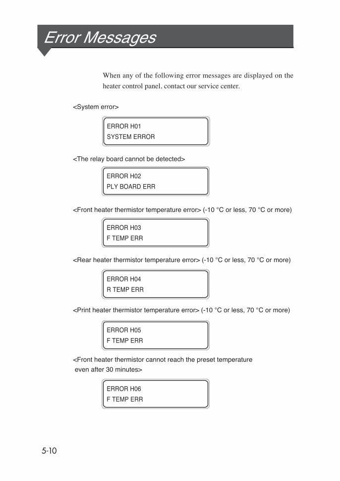
5-10
ERROR H01
SYSTEM ERROR
ERROR H02
PLY BOARD ERR
ERROR H03
F TEMP ERR
ERROR H04
R TEMP ERR
ERROR H05
F TEMP ERR
ERROR H06
F TEMP ERR
Error Messages
When any of the following error messages are displayed on the
heater control panel, contact our service center.
<System error>
<The relay board cannot be detected>
<Front heater thermistor temperature error> (-10 °C or less, 70 °C or more)
<Rear heater thermistor temperature error> (-10 °C or less, 70 °C or more)
<Print heater thermistor temperature error> (-10 °C or less, 70 °C or more)
<Front heater thermistor cannot reach the preset temperature
even after 30 minutes>

5-11
Sect
ion
5 H
eate
r C
ontro
ller
Men
u O
pera
tion
<Rear heater thermistor cannot reach the preset temperature even after
30 minutes.>
<Printer heater thermistor cannot reach the preset temperature even after
30 minutes.>
<Switch test error occurs in the diagnostics >
<Zero cross error occurs in the diagnostics.>
ERROR H08
P TEMPERR
R TEMPERR
ERROR H10
ZERO CROSS ERROR
ERROR H09
SWITCH ERROR
Error Messages
6-1
Sect
ion
6 T
roub
lesh
ootin
g
Section 6 Troubleshooting
This section describes troubleshooting for the printer. If the prob-
lem cannot be solved, contact your dealer or our service center.
Troubleshooting
Clearing Jams
When an Error Message Appears
When the Printer Fails to Work Correctly
When a Print Error Occurs
When There is an Abnormal Sound
When It is Desired to Move the Printer
Contents of This Section

6-2
TroubleshootingBefore deciding that there is a serious problem with the printer,check the following items.
Items to be checked
Symptom Items to be checked Corrective measures
No power
Power cable connection Plug the power cable into the outlet correctly.
Power supply to the outlet Supply power to the outlet.
Power switch ON/OFF Turn the power switch ON.See Section 2, Turning Power ON/OFF.
The paper guide is notheated even when theheater is turned ON.
Printer statusThe paper guide is heated during printing.Be sure the paper guide is heated by printing the testpattern.
Heater control panelPress the desired heater ON key (FRONT/PRINT/REAR)again and then be sure the paper guide is heated byprinting the test pattern.
Check power supply voltage Connect to 200VAC.
The printer fails to startor operate correctly.
ERROR lamp and message onthe LCD
Take appropriate action according to the error message.See Section 6, When an Error Message Appears.
Cannot print.
Interface cable connection Connect the interface cable correctly.See Section 2, Turing Power ON/OFF.
ERROR lamp and message onthe LCD
Take appropriate action according to the error message.See Section 6, When an Error Message Appears.
ERROR lamp OFF Print nozzle adjustment pattern. See Section 3, MechanicalAdjustment Menu.
Transmitted data are notprocessed immediately DATA lamp (flashing?) Check the communication conditions to the computer.
Poor print quality
Media type
Check for improvement by changing the settings of heatertemperature, print mode, RIP, etc. If there is noimprovement, the media is not suitable for the ink. Replacethe media with another type.
Ink type Use our recommended ink.See Appendix, Consumables.
Ink head cleaning Clean the ink head.See Section 2, Head Cleaning.
Color stripe is not set. Set the color stripe.See, Section 3 Entry Menu, (14) Color stripe setting.
Gaps in color printing at a lowprinting rate.
Set the head mode to HIGHLIGHT PRIORITY.See Section 3, Entry Menu, (15) Head action mode setting.Set smaller interval value.See Section 3 Entry Menu, (30) Wait interval setting.
Operation temperature Use the printer in 20° C to 25° C temperature.
Media jams occurfrequently
Media type
Check whether the media type setting matches the type ofthe loaded media. See Section 2, Installing Media Roll inthe Printer and Removing the media roll from the Printer.Use our recommended media.See Appendix, Consumables.
Media setting Set the media correctly.See Section 2, Replacing the Media Roll.
Check whether there is anyforeign material in the carriagepath or the media path.
Remove any foreign material.See Section 6, Clearing Media Jams.
Suction FANTry weakening the suction power of the suction FAN.See Section 6, When an error message appears "Mediajam"
Heater temperature settingTry lowering the heater temperature setting.See Section 6, When an error message appears "Mediajam"
Printing is slow Operation temperature Use the printer in 20 to 25 ° C temperature.

6-3
Sect
ion
6 T
roub
lesh
ootin
g
Clearing JamsClear media jams according to the guidance message displayed on
the LCD.
1 A guidance message appears on the LCD.
2 Open the pressure roller up/down lever and rear cover.
3 Remove the jammed media, check that there are no
obstacles in the carriage path and the media transport
path, and close the rear cover.
4 The carriage will move to its home position.
5 Set the media according to “Installing Media Roll in the
Printer and Removing the Media Roll from the Printer”.
(See page 2-12.)
X: Types of media jam0: Media jam 01: Media jam 1
2: Media jam 2
LIFT LEVER & X
OPEN REAR COVER
REMOVE PAPER
CLOSE REAR COVER
CARRIAGE MOVING
WAIT A MOMENT
Carriage
See “When an Error Message Appears”.
Carriage
Rear coverPressure roller up/down lever
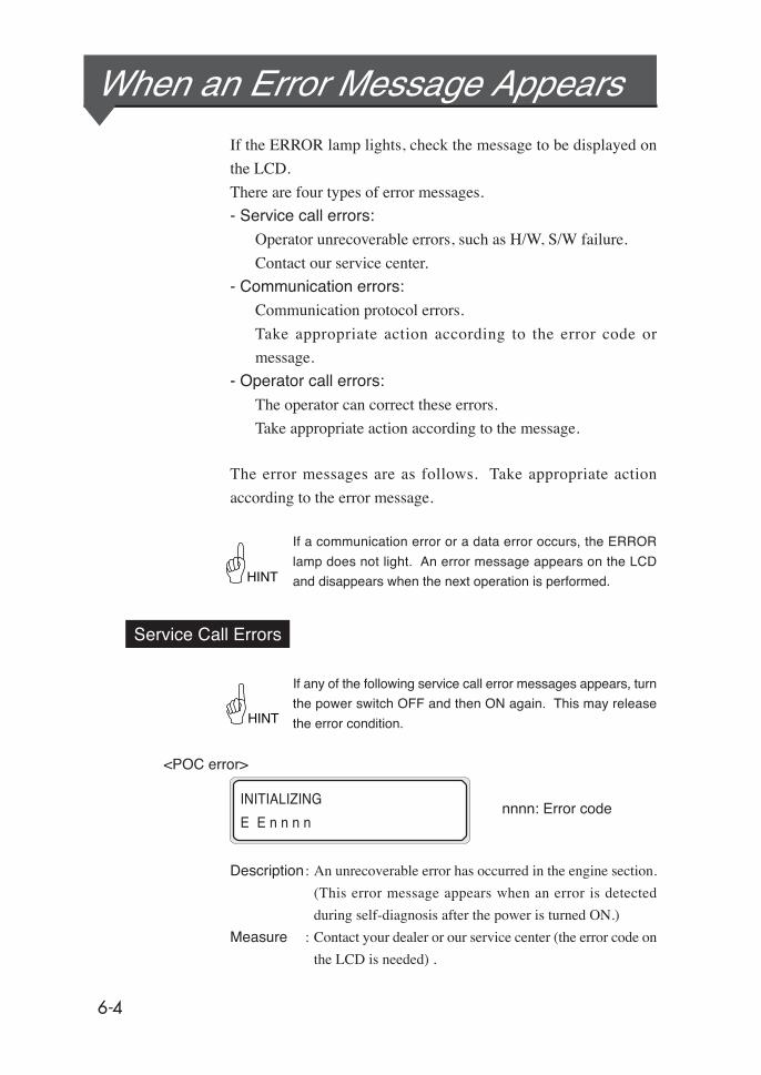
6-4
When an Error Message AppearsIf the ERROR lamp lights, check the message to be displayed on
the LCD.
There are four types of error messages.
- Service call errors:
Operator unrecoverable errors, such as H/W, S/W failure.
Contact our service center.
- Communication errors:
Communication protocol errors.
Take appropriate action according to the error code or
message.
- Operator call errors:
The operator can correct these errors.
Take appropriate action according to the message.
The error messages are as follows. Take appropriate action
according to the error message.
If a communication error or a data error occurs, the ERROR
lamp does not light. An error message appears on the LCD
and disappears when the next operation is performed.
Service Call Errors
If any of the following service call error messages appears, turn
the power switch OFF and then ON again. This may release
the error condition.
<POC error>
nnnn: Error code
Description : An unrecoverable error has occurred in the engine section.
(This error message appears when an error is detected
during self-diagnosis after the power is turned ON.)
Measure : Contact your dealer or our service center (the error code on
the LCD is needed) .
HINT
HINT
INITIALIZING
E E n n n n
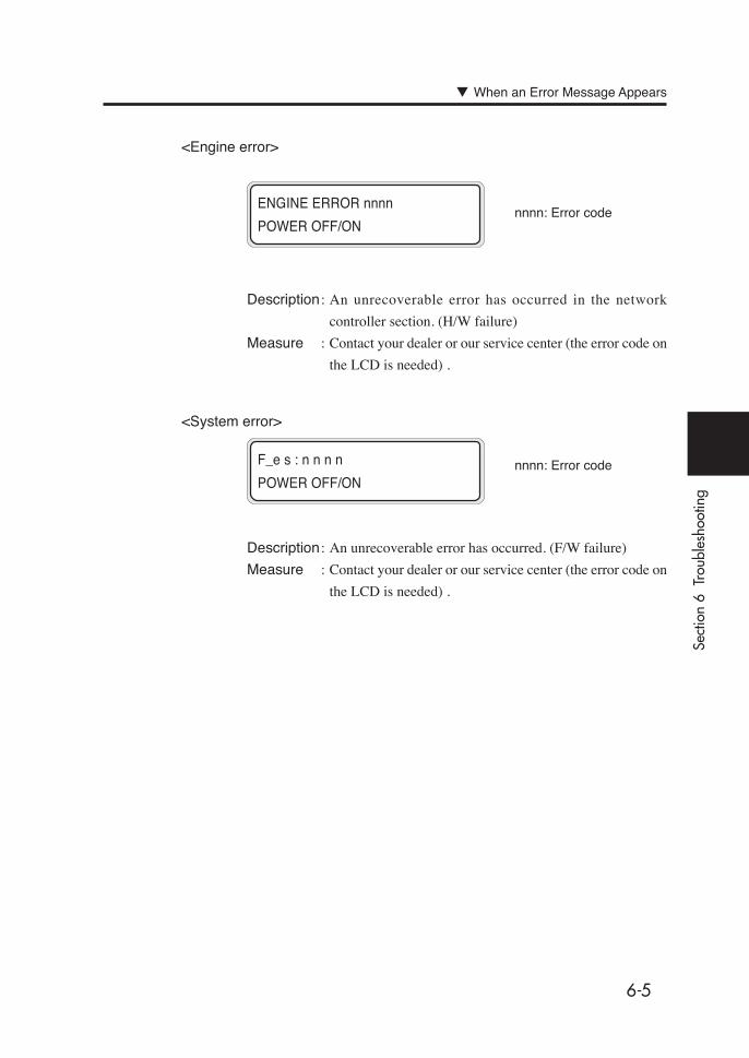
6-5
Sect
ion
6 T
roub
lesh
ootin
g
<Engine error>
nnnn: Error code
Description : An unrecoverable error has occurred in the network
controller section. (H/W failure)
Measure : Contact your dealer or our service center (the error code on
the LCD is needed) .
ENGINE ERROR nnnn
POWER OFF/ON
<System error>
nnnn: Error code
Description : An unrecoverable error has occurred. (F/W failure)
Measure : Contact your dealer or our service center (the error code on
the LCD is needed) .
F_e s : n n n n
POWER OFF/ON
When an Error Message Appears

6-6
Communication Errors
nnn: Error code
001: Parity error
002: Bus timeout error
Description : The condition or protocol for communication with the
computer is incorrect.
Measure : (1) Check the SCSI cable connection and terminator
switch.
(2) Set the host SCSI parity bit generation setting to ON.
(3) Check the host SCSI driver setting.
PRINT READY
W SCSI ERROR nnn

6-7
Sect
ion
6 T
roub
lesh
ootin
g
Operator Call Errors
The following errors can be corrected by the operator.
(AC2 power supply)
Description : The power switch on the AC2 side is not turned ON.
Measure : Turn the power switch on the AC2 side ON, and turn the
printer power OFF andON.
=> "Section 2 Basic Operations (Turning the Power ON/OFF)"
(Ink cartridge)
Description : There is no ink.
Measure : Take appropriate action according to the message.
=> Section 2 Basic Operations (Ink Cartridge Replacement)
Description : An ink cartridge error has occurred.
Measure : Take appropriate action according to the message.
=> Section 2 Basic Operations (Ink Cartridge Replacement)
Description : No ink cartridge is installed.
Measure : Take appropriate action according to the message.
=> Section 2 Basic Operations (Ink Cartridge Replacement)
OPEN X INKCOVER Z
CHECK YY INK
X: L (left) /R (Right)
YY: Y, M, C, Bk, Lm, Lc
X: L (left) /R (Right)
YY: Y, M, C, Bk, Lm, Lc
Z: Error code (1 to 9)
OPEN X INKCOVER
SET YY INK
When an Error Message Appears
X: L (left) /R (Right)
YY: Y, M, C, Bk, Lm, Lc
OPEN X INKCOVER
CHANGE YY INK
CHECK AC2 POWER
POWER ON/OFF

6-8
Description : The ink cover is open.
Measure : Take appropriate action according to the message.
- The ink LED flashes.
Description : Ink is running out. (Warning)
Measure : Have a new ink cartridge ready.
(Waste ink bottle)
Description : The waste ink bottle is full.
Measure : Take appropriate action according to the message.
=> Section 2 Basic Operations (Waste Ink Bottle Replacement)
Description : No waste ink bottle is installed.
Measure : Take appropriate action according to the message.
=> Section 2 Basic Operations (Waste Ink Bottle Replacement)
WASTE INK FULL
CHANGE BOTTLE
BOTTLE ISN’T SET
SET BOTTLE
INKCOVER IS OPEN
CLOSE X INKCOVERX: L (left) /R (Right)
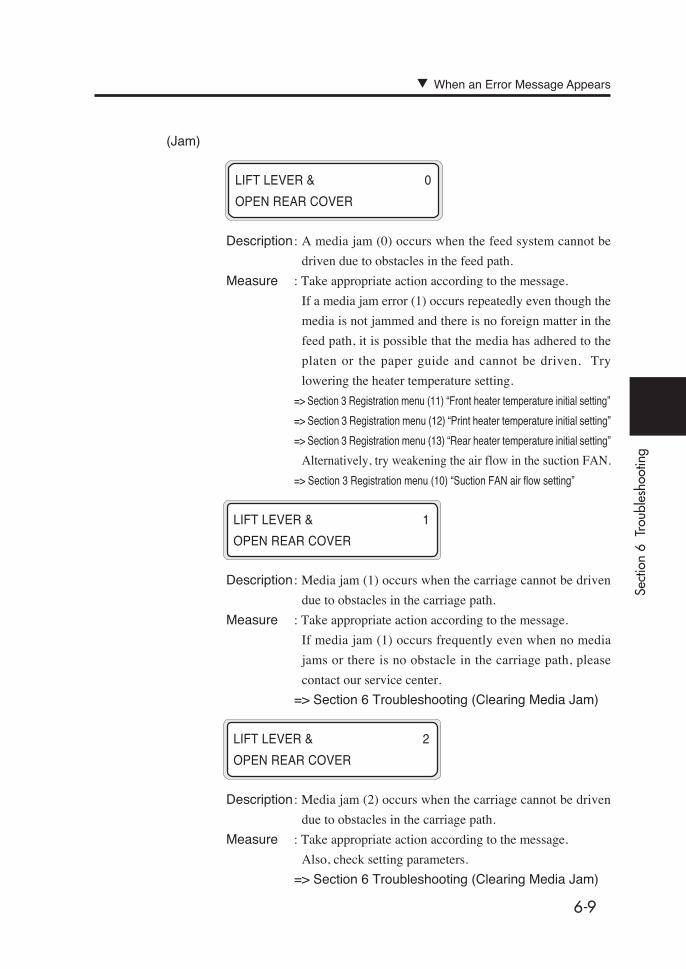
6-9
Sect
ion
6 T
roub
lesh
ootin
g
(Jam)
Description : A media jam (0) occurs when the feed system cannot be
driven due to obstacles in the feed path.
Measure : Take appropriate action according to the message.
If a media jam error (1) occurs repeatedly even though the
media is not jammed and there is no foreign matter in the
feed path, it is possible that the media has adhered to the
platen or the paper guide and cannot be driven. Try
lowering the heater temperature setting.
=> Section 3 Registration menu (11) “Front heater temperature initial setting”
=> Section 3 Registration menu (12) “Print heater temperature initial setting”
=> Section 3 Registration menu (13) “Rear heater temperature initial setting”
Alternatively, try weakening the air flow in the suction FAN.
=> Section 3 Registration menu (10) “Suction FAN air flow setting”
Description : Media jam (1) occurs when the carriage cannot be driven
due to obstacles in the carriage path.
Measure : Take appropriate action according to the message.
If media jam (1) occurs frequently even when no media
jams or there is no obstacle in the carriage path, please
contact our service center.
=> Section 6 Troubleshooting (Clearing Media Jam)
Description : Media jam (2) occurs when the carriage cannot be driven
due to obstacles in the carriage path.
Measure : Take appropriate action according to the message.
Also, check setting parameters.
=> Section 6 Troubleshooting (Clearing Media Jam)
LIFT LEVER & 0
OPEN REAR COVER
LIFT LEVER & 1
OPEN REAR COVER
LIFT LEVER & 2
OPEN REAR COVER
When an Error Message Appears

6-10
Description : Media runs out.
Measure : Set new media.=> Section 2 Basic Operations (Media Replacement)
Description : Media with an invalid size (less than 297 mm width or 104inch width or more) is set.
Measure : Set media with a correct size.
=> Section 2 Basic Operations (Media Replacement)
Description : Media is skewed.
Measure : Set media correctly. Ink may adhere to the platen because of the skew. Wipe
ink off the platen.
=> Section 2 Basic Operations (Media Replacement)
Description : The lever is in the up position.
Measure : Set media according to the message.
- Error LED is blinking
Description : Take-up failed in the winder.
Measure : Remove the media in the vicinity of the take-up sensor.
Check if the media is set correctly.
=> Section 2 Installing Media in Winder
LIFT LEVER
CHECK PAPER
LIFT LEVER
SET PAPER
LIFT LEVER
SET PAPER
(Media)
SET PAPER
PUSH DOWN LEVERXX: Ink color

6-11
Sect
ion
6 T
roub
lesh
ootin
g
(Others)
Description : The rear cover is opened.
Measure : Take appropriate action according to the message.
Description : The head temperature is out of the operating temperature
range.Measure : Stay within the operating temperature range. Leave the
printer idle for a while until the head temperature falls
within the range.
Description : The ambient temperature is not within the operatingtemperature range for the printer.
Measure : Stay within the operating temperature range (15 °C to
30 °C).
Description : It is about time to change the cap pump.
Measure : Please contact our service center to have the cap pumpchanged.
Description : It is about time to change the ink supply pump.Measure : Please contact our service center to have the ink supply
pump changed.
CLOSE REAR COVER
HEAD TEMP. ERROR
WAIT A MOMENT
ENV. TEMP. ERROR
CHANGE CONDITION
TIME TO CHANGE
CAP PUMP
TIME TO CHANGE
XX PUMP
When an Error Message Appears
XX: Ink color
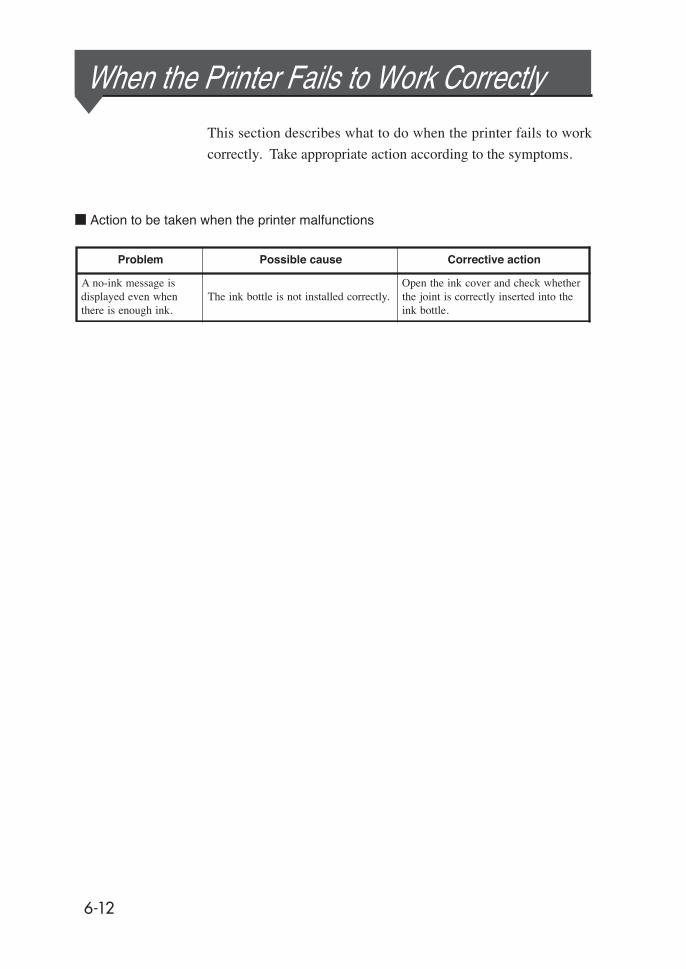
6-12
When the Printer Fails to Work Correctly
This section describes what to do when the printer fails to work
correctly. Take appropriate action according to the symptoms.
Action to be taken when the printer malfunctions
Problem Possible cause Corrective action
A no-ink message isdisplayed even whenthere is enough ink.
The ink bottle is not installed correctly.Open the ink cover and check whetherthe joint is correctly inserted into theink bottle.

6-13
Sect
ion
6 T
roub
lesh
ootin
g
When a Print Error OccursThis section explains how to solve print quality problems. Take
appropriate action according to the symptoms.
Action to solve print quality problems when a print error occurs
Symptom Possible cause Corrective action
A blank sheet is outputor the printed drawing isfaded.
Blank data are transmitted. Check print data.
The environmental conditions do notmeet the printer specifications.
Use the printer in the specifiedenvironmental conditions (temperatureand humidity). (See "Section 1,Environmental Conditions".)
The media is set incorrectly. Check the media settings.
Parts of a drawing aremissing or the printing isunclear.
Foreign matter is adhering to the head.Clean the head from the CLEANINGmenu.
A low printing ratio pattern is printedcontinuously at high temperatureenvironment.
Set the head mode to HIGHLIGHTPRIORITY.
The printing is blurred.
The media is loaded upside down.Check whether the media is loadedcorrectly.
The media is set incorrectly. Check the media settings.
Heater temperature is low. Raise the set temperature of the heater.
The printing is stained.
The leading edge of the media iscurled.
Check whether the leading edge of themedia is curled. If it is curled, cut theleading edge.
The media is slightly folded orwinkled.
If it is wrinkled, feed the media andcut off the wrinkled part of the media.
The platen is stained.Clean the platen, referring to "Section2, Inspection & Maintenance".
The media edge guard setting isincorrect.
Set the media edge guard correctly.
Parts of a drawing aremissing at the start ofprinting.
Ambient temperature.Use the printer in the specifiedenvironmental conditions.
Parts of a drawing aremissing even whencleaning is performedrepeatedly.
The nozzle is clogged. Perform fill cap operation.
Poor printing cannot beimproved even whencleaning is performed.
The cap or wiper is stained.Check whether the cap and wiper arestained.If they are stained, clean them.

6-14
When There is an Abnormal SoundIf an abnormal sound is heard, contact your agent or an SIIT ser-
vice center.
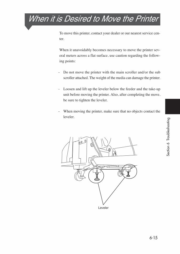
6-15
Sect
ion
6 T
roub
lesh
ootin
g
Leveler
When it is Desired to Move the PrinterTo move this printer, contact your dealer or our nearest service cen-
ter.
When it unavoidably becomes necessary to move the printer sev-
eral meters across a flat surface, use caution regarding the follow-
ing points:
- Do not move the printer with the main scroller and/or the sub
scroller attached. The weight of the media can damage the printer.
- Loosen and lift up the leveler below the feeder and the take-up
unit before moving the printer. Also, after completing the move,
be sure to tighten the leveler.
- When moving the printer, make sure that no objects contact the
leveler.

A-1
App
endi
x
This Appendix shows the basic specifications, components,
and Celsius and Fahrenheit conversion table.
Contents of This Section
Basic Specifications
Appendix

A-2
Basic Specifications
Printer Specifications
Basic printer specifications
meIt noitcnuF/noitacificepS
dohtemgnidroceR ngitnirptej-knirolocepyt-ozeiP
noituloseR )noitceridnacsbus(ipd0272x)noitceridnacsniam(ipd045,ipd0272xipd027
deepsgnidroceRgnidnuorrusotgnidroccasegnahC(.gnitnirpssap4htiw0A/setunimruoftuobA
e.)rutarepmetdaehdnaerutarepmet
dischage direction/deefMedia Front feed, rear discharge
espytMedia ceafelbixelF,nilaupraT,edirolhclyniV
htdiwMedia chesni401mumixaM
egdirtracknI)naycthgil,atnegamthgil,wolley,atnegam,nayc,kcalb(srolocxiS
selttobknilm0001
esioNsselro)A(Bd54:ybdnatS
)dnuossuounitnoC(sselro)A(Bd06:gnitarepO
tuptuotaeH sselroH/J0000405:retaeH,sselroH/J000027:retnirP
deetnaraugtnirpmumixaMegnar
)mm5(snigramtfeldnathgirdna)mm5(snigrammottob,potgnidulcxeaerA).mm01eblliwmarginstfeldnathgir,draugegderepapehtgnisunehW(
ylppusrewopdetaRzH06/zH05A1:1CAzH06/zH05A8:2CA
egnartupniylppusrewoPzH1±zH06/zH05%01±0VAC32-VAC 002:1CAzH1±zH06/zH05%01±0VAC32-VAC002
0VAC -32-VAC0020VAC -32-VAC002
:2CA
noitpmusnocrewoP
noitpmusnocrewopmumixaMsselroW002:1CA
sselroW0041:2CAsselroW0081
rewopevitalumuCsselrohW031:1CA
)tupniVAC002ta(sselrohW053:2CA)tupniVAC032ta(
)tupniVAC002ta()tupniVAC032ta(
sselrohW004moortaC5˚4ottessretaehllahtiwgnitnirpsuounitnocniseulavlacipyT(
)C0˚2erutarepmet
snoisnemidlanretxE mm01±)H(mm0121x)D(mm098x)W(mm0173
thgieW
Printing guaranteed range
k)nidnallormediagnidulcxe(sselrogk005
ytidimuh/erutarepmetgnitarepOegnar
nednocon(HR%07ot%03/C0˚3ot5˚1
sation)
sation)
sation)
nednocon(HR%06ot%04/C5˚2ot0˚2
nednocon(sselroHR%08ot%01/C5˚3ot5˚
ecapsnoitallatsnI )H(mm0071x)D(mm0092x)W(mm0054
ecapsecnanetniaM H)(mm0071x)D(mm0092x)W(mm0054
Temperature/humidity range while printer is idle or in long-term storage