
Solvent Engineering for High-Performance PbS Quantum Dots ...
13
nanomaterials Article Solvent Engineering for High-Performance PbS Quantum Dots Solar Cells Rongfang Wu 1,† , Yuehua Yang 1,† , Miaozi Li 3 , Donghuan Qin 1, * ID , Yangdong Zhang 2 and Lintao Hou 2, * 1 Institute of Polymer Optoelectronic Materials & Devices, State Key Laboratory of Luminescent Materials & Devices, South China University of Technology, Guangzhou 510640, China; [email protected] (R.W.); [email protected] (Y.Y.) 2 Siyuan Laboratory, Guangzhou Key Laboratory of Vacuum Coating Technologies and New Energy Materials, Guangdong Provincial Key Laboratory of Optical Fiber Sensing and Communications, Department of Physics, Jinan University, Guangzhou 510632, China; [email protected] 3 School of Materials Science and Engineering, South China University of Technology, Guangzhou 510640, China; [email protected] * Correspondence: [email protected] (D.Q.); [email protected] (L.H.); Tel.: +86-20-87114346 (D.Q.) † These authors contribute equally. Received: 3 July 2017; Accepted: 25 July 2017; Published: 28 July 2017 Abstract: PbS colloidal quantum dots (CQDs) solar cells have already demonstrated very impressive advances in recent years due to the development of many different techniques to tailor the interface morphology and compactness in PbS CQDs thin film. Here, n-hexane, n-octane, n-heptane, isooctane and toluene or their hybrids are for the first time introduced as solvent for comparison of the dispersion of PbS CQDs. PbS CQDs solar cells with the configuration of PbS/TiO 2 heterojunction are then fabricated by using different CQDs solution under ambient conditions. The performances of the PbS CQDs solar cells are found to be tuned by changing solvent and its content in the PbS CQDs solution. The best device could show a power conversion efficiency (PCE) of 7.64% under AM 1.5 G illumination at 100 mW cm -2 in a n-octane/isooctane (95%/5% v/v) hybrid solvent scheme, which shows a ~15% improvement compared to the control devices. These results offer important insight into the solvent engineering of high-performance PbS CQDs solar cells. Keywords: colloidal quantum dots; solar cells; PbS; solvent engineering 1. Introduction Colloidal quantum dots (CQDs) heterojunction solar cells that can be fabricated by simple solution-processing techniques are under intensive research due to their potential for low cost, air stable and large area efficient photovoltaic devices [1–10]. Among all kinds of CQDs, PbS CQDs allow bandgap tuning easily through the quantum size effect by changing the diameter of CQDs, which allows efficient light harvesting over a wide range of the visible/infrared wavelength in multiple junction solar cells formed by single material [11–14]. The most common and efficient PbS CQDs solar cells architecture consists of PbS CQDs active layer and TiO 2 or ZnO electron acceptor layer to form depleted heterojunction. Comparing with the PbS CQDs solar cells in configuration of Schottky diode or normal device architecture, PbS/TiO 2 -depleted device with the inverted structure has many merits. For example, the placement of the junction on the illuminated side reduces the recombination rate of minority carriers [15]. On the other hand, the band alignment of PbS CQDs and TiO 2 will block holes transfer to TiO 2 at the interface. Thanks to the development of materials and device processing techniques, the power conversion efficiency (PCE) of CQD solar cells has increased from 0.00004% [16] in 2005 to certified 10.6% [17] in 2016. Due to the large surface to volume ratio in CQDs Nanomaterials 2017, 7, 201; doi:10.3390/nano7080201 www.mdpi.com/journal/nanomaterials
Transcript of Solvent Engineering for High-Performance PbS Quantum Dots ...

nanomaterials
Article
Solvent Engineering for High-Performance PbSQuantum Dots Solar Cells
Rongfang Wu 1,†, Yuehua Yang 1,†, Miaozi Li 3, Donghuan Qin 1,* ID , Yangdong Zhang 2
and Lintao Hou 2,*1 Institute of Polymer Optoelectronic Materials & Devices, State Key Laboratory of Luminescent Materials &
Devices, South China University of Technology, Guangzhou 510640, China; [email protected] (R.W.);[email protected] (Y.Y.)
2 Siyuan Laboratory, Guangzhou Key Laboratory of Vacuum Coating Technologies and New EnergyMaterials, Guangdong Provincial Key Laboratory of Optical Fiber Sensing and Communications,Department of Physics, Jinan University, Guangzhou 510632, China; [email protected]
3 School of Materials Science and Engineering, South China University of Technology, Guangzhou 510640,China; [email protected]
* Correspondence: [email protected] (D.Q.); [email protected] (L.H.); Tel.: +86-20-87114346 (D.Q.)† These authors contribute equally.
Received: 3 July 2017; Accepted: 25 July 2017; Published: 28 July 2017
Abstract: PbS colloidal quantum dots (CQDs) solar cells have already demonstrated very impressiveadvances in recent years due to the development of many different techniques to tailor the interfacemorphology and compactness in PbS CQDs thin film. Here, n-hexane, n-octane, n-heptane, isooctaneand toluene or their hybrids are for the first time introduced as solvent for comparison of thedispersion of PbS CQDs. PbS CQDs solar cells with the configuration of PbS/TiO2 heterojunction arethen fabricated by using different CQDs solution under ambient conditions. The performances ofthe PbS CQDs solar cells are found to be tuned by changing solvent and its content in the PbS CQDssolution. The best device could show a power conversion efficiency (PCE) of 7.64% under AM 1.5 Gillumination at 100 mW cm−2 in a n-octane/isooctane (95%/5% v/v) hybrid solvent scheme, whichshows a ~15% improvement compared to the control devices. These results offer important insightinto the solvent engineering of high-performance PbS CQDs solar cells.
Keywords: colloidal quantum dots; solar cells; PbS; solvent engineering
1. Introduction
Colloidal quantum dots (CQDs) heterojunction solar cells that can be fabricated by simplesolution-processing techniques are under intensive research due to their potential for low cost, airstable and large area efficient photovoltaic devices [1–10]. Among all kinds of CQDs, PbS CQDs allowbandgap tuning easily through the quantum size effect by changing the diameter of CQDs, whichallows efficient light harvesting over a wide range of the visible/infrared wavelength in multiplejunction solar cells formed by single material [11–14]. The most common and efficient PbS CQDssolar cells architecture consists of PbS CQDs active layer and TiO2 or ZnO electron acceptor layer toform depleted heterojunction. Comparing with the PbS CQDs solar cells in configuration of Schottkydiode or normal device architecture, PbS/TiO2-depleted device with the inverted structure has manymerits. For example, the placement of the junction on the illuminated side reduces the recombinationrate of minority carriers [15]. On the other hand, the band alignment of PbS CQDs and TiO2 willblock holes transfer to TiO2 at the interface. Thanks to the development of materials and deviceprocessing techniques, the power conversion efficiency (PCE) of CQD solar cells has increased from0.00004% [16] in 2005 to certified 10.6% [17] in 2016. Due to the large surface to volume ratio in CQDs
Nanomaterials 2017, 7, 201; doi:10.3390/nano7080201 www.mdpi.com/journal/nanomaterials

Nanomaterials 2017, 7, 201 2 of 13
materials, substantial unsaturated dangling bonds will create electronic trap states, which will promotethe recombination of charge carriers that is detrimental to the CQDs solar cells performance [13].To overcome this drawback, a series of ligands strategies including organic, organic–inorganic hybridor atomic ligands have been developed to passivate trap states of CQDs and a dramatic improvementin device performance is obtained [18–21]. Band alignment between the PbS CQDs and TiO2 is alsocritical for favoring electron injection to the conduction band of TiO2. For example, by doping TiO2
with Sb or Zr [22], great improvement of PCEs was obtained in CQD solar cells arising mainly froman increase in short-circuit current (Jsc). Another way to improve the CQD solar cells performance isdecreasing the recombination at the metal oxide-semiconductor interface. In this strategy, introducingpassivation ligands [23–26] around CQD can increase the width of the depletion region and optimizethe electron collecting efficiency.
Improvements in PbS CQDs solar cells can further offer guidance on better understandingas well as eliminating the factors that affect device performance. As a high ratio of surface areato volume existed in PbS CQDs solar cells, reducing the number of recombination centers is amost important way for achieving high device performance [27–32]. In particular, the nature ofthe morphology and compactness of PbS CQDs thin film are key factors that determine solar cellsperformance. The evaporating rate, viscosity and dispersability of solvent will affect the aggregationsand the compactness of CQDs film. In the previous research, however, few works have been focusedon the solvent effects on the device performance. n-octane is widely used as a single solvent forthe preparation of PbS CQDs solution. The boiling point of n-octane is as high as 125.7 C, sopostponed annealing at ~50 C for up to 10 h must be carried out after the deposition of PbS CQDsfilm in order to remove the existed solvent. Most recently, Lan et al. [17] employed a co-solvent(toluene and dimethylformamide) to incorporate iodide on CQDs before device fabrication. Theyfound that improved passivation was obtained, which resulted in a certified efficiency of 10.6%.Herein, for the sake of adjusting the evaporating rate and viscosity of n-octane, we selected n-hexane,n-heptane, isooctane, toluene, n-octane and their hybrid as solvent for the dispersion of PbS CQDs.As shown in Table 1, the boiling point for n-heptane, isooctane, toluene and n-hexane is 99, 98, 111and 69 C, lower than that of n-octane (125.7 C). On the other hand, toluene has high polarity of2.4 in comparison to other solvents used in this case. Devices with configuration of FTO (F dopedSnO2)/ZnO/TiO2/PbS/Au are then fabricated by using these PbS CQDs solutions. We find thatthe performance of PbS CQDs solar cells is highly dependent on the content of solvent used.In single-solvent strategy, devices show high efficiency up to 6.0% in the case of toluene or n-octanesolvent, while only 4~5% efficiency is obtained in the case of isooctane, hexane or heptanes solvent.It should be noted that, in the hybrid solvent scheme, the device performance can be further improved.For example, by adding less than 20% (v/v) isooctane into n-octane, the PCE is higher than that withpure n-octane and as high as 7.64% PCE is obtained in 5% isooctane/95% (v/v) n-octane mixture.Our research gives more insight into the solvent engineering for achieving high-performance PbSCQDs solar cells.
Table 1. Summarized properties of different solvent.
Solvent Name Polarity Viscosity (Pa·s) Boiling Point (C) Absorption Wavelength (nm)
n-octane 0.06 0.53 125 200isooctane 0.10 0.53 99 210heptane 0.20 0.41 98 200
n-hexane 0.06 0.33 69 210toluene 2.40 0.59 111 285
2. Experiment Procedure
2.1. Materials
Zinc acetate hydrate, ethanol amine, 2-methoxyethanol, titanium butoxide, triethanolamine,mercaptopropionic acid, hexamethyldisilathiane (TMS) and octyl-phosphine acid (OPA) were

Nanomaterials 2017, 7, 201 3 of 13
purchased from Aladdin (Shanghai, China). Oleic acid (OA), lead oxide, oleic amine (OLA), 1-octadece(ODE) were purchased from Alfa Aesar (Beijing, China). All chemicals were used directly without anyfurther purification.
2.2. Ti-Sols, Zn2+ Precursor and PbS CQDs Fabrication
The preparation of Ti-sols was carried out under ambient condition, as described in theliterature [24]. Zn2+ precursor was prepared by adding zinc acetate and ethanolamine into thesolution of 2-methoxyethanol with a concentration of 0.5 mol L−1. The resulting solution was refluxedat 60 C for 2 h under ambient conditions. The final Zn2+ precursor was filtered through 0.45 µm filterbefore use. PbS CQDs were prepared by a typical synthetic procedure on a literature method [32].A typical synthetic procedure was given below: in a three-necked flask, 0.45 g PbO, 1.5 mL OA, and16.5 mL ODE were added. The mixtures were heated to 120 C and pumped down for 6 h to removeany moisture and impurity. Then high purity (>99.99%) N2 was introduced to the flask; 0.20 mL TMSwas mixed with 5 mL 1-octadece in a syringe and quickly injected into the mixture. The hotplate wasremoved away immediately after the injection and the mixture was cooled down to ~90 C. At thesame time, hybrid ligands were prepared by mixing 0.72 mmol CdCl2, 2 mL OLA, and 0.048 mmolOPA in a three-necked flask and degassed/refluxed at 90 C. The hybrid ligands were injected intoPbS CQDs mixture at this temperature and the reaction was cooled down to room temperature. Afterwashing and centrifugation, PbS CQDs were dissolved into different solvents or hybrid solvent with aconcentration of 25 mg/mL.
2.3. Devices Fabrication
PbS/TiO2 CQDs heterojunction solar cells with a triple-layer structure, containing ZnO windowlayer, transparent TiO2 layer and PbS CQDs light absorber layer, were prepared according to aprocedure reported before [32]. Firstly, FTO glass was cleaned in deionized (DI) water and isopropanolsolution for 10 min under ultrasonic treatment. Zn2+ precursor was then deposited on cleaned FTOsubstrate at 2500 rpm for 15 s and put on a hot plate at 300 C for 30 min to remove any organic solventand impurity. One layer of Ti-sols was then spin-coated on the FTO/ZnO substrate at 2500 rpm for15 s, following annealing at 500 C for 1 h. After cleaning and drying, several drops of PbS CQDsin different solvents were put onto the FTO/ZnO substrate and spin-casted at 3000 rpm for 15 s.3-Mercaptopropionic acid (MPA) was used for ligands exchange, as described in the literature [31].It should be noted that the one-step coating PbS CQDs layer thickness for different solvents aredifferent due to the difference in solvent volatilizing rate. In order to obtain PbS CQDs film withsimilar thickness of ~200 nm, for PbS/n-octane solution, four layers of PbS CQDs should be deposited,while five layers of PbS CQDs for PbS/toluene solution, five layers for PbS/isooctane solution andfive layers of PbS CQDs for PbS/heptane solution.
3. Results and Discussion
The TEM image (see Figure 1a) suggests that the CQDs are highly crystalline and homogeneouswith average diameter 4.5 nm. The absorption spectra of PbS CQDs in different organic solvent areshown in Figure 1b. The PbS CQDs are purified by twice precipitating with acetone and ethanol.Following this, the products are re-dispersed in n-octane, isooctane, n-heptane, n-hexane and toluenewith the same concentration of 25 mg/mL. It is mentioned that PbS CQDs can be well dispersed inall the above solvents even with a concentration up to 80 mg/mL, as shown in the inset of Figure 1b.The initial absorption spectrum peak for all PbS CQDs samples is located at ~1080 nm with full widthat half maximum of ~150 nm, which indicates that these kinds of solvents do not have any changes onthe physical properties of PbS CQDs. It is also found that there are almost no changes in absorptionspectrum for the PbS CQDs samples after storage for several weeks, which implies that the PbS CQDssamples fabricated by the above means are very stable. This phenomenon can be explained by the

Nanomaterials 2017, 7, 201 4 of 13
successfully hybrid passivation strategy adopted in this case (PbS CQDs is passivated by CdCl2 + OPA+ OLA), which is also confirmed by Sargent et al. [25].Nanomaterials 2017, 7, x FOR PEER REVIEW 4 of 12
Figure 1. (a) TEM image of as prepared PbS CQDs (b) UV-absorption spectra of PbS CQDs in different solvents. CQD = colloidal quantum dots.
The device configuration of PbS CQDs solar cells are provided in Figure 2a. A 40 nm layer of ZnO thin film is deposited on FTO substrate by thermal decomposition of zinc acetate to make a smooth and defects-free surface. Two layers of TiO2 film (~100 nm) is then deposited on ZnO to create an electron acceptor layer. PbS CQDs in different solvents are then spin-coated on top of the FTO/ZnO/TiO2 substrate. To eliminate the thickness effects on the solar cells performance, all PbS CQDs film are controlled to have similar thickness by using the same device processing technique. A typical cross-section SEM view of PbS CQDs solar cells device is shown in Figure 2b. The PbS CQDs active layer is very compact and homogeneous with the thickness around 200 nm.
Figure 1. (a) TEM image of as prepared PbS CQDs (b) UV-absorption spectra of PbS CQDs in differentsolvents. CQD = colloidal quantum dots.
The device configuration of PbS CQDs solar cells are provided in Figure 2a. A 40 nm layer ofZnO thin film is deposited on FTO substrate by thermal decomposition of zinc acetate to make asmooth and defects-free surface. Two layers of TiO2 film (~100 nm) is then deposited on ZnO tocreate an electron acceptor layer. PbS CQDs in different solvents are then spin-coated on top of theFTO/ZnO/TiO2 substrate. To eliminate the thickness effects on the solar cells performance, all PbSCQDs film are controlled to have similar thickness by using the same device processing technique.A typical cross-section SEM view of PbS CQDs solar cells device is shown in Figure 2b. The PbS CQDsactive layer is very compact and homogeneous with the thickness around 200 nm.
Nanomaterials 2017, 7, x FOR PEER REVIEW 4 of 12
Figure 1. (a) TEM image of as prepared PbS CQDs (b) UV-absorption spectra of PbS CQDs in different solvents. CQD = colloidal quantum dots.
The device configuration of PbS CQDs solar cells are provided in Figure 2a. A 40 nm layer of ZnO thin film is deposited on FTO substrate by thermal decomposition of zinc acetate to make a smooth and defects-free surface. Two layers of TiO2 film (~100 nm) is then deposited on ZnO to create an electron acceptor layer. PbS CQDs in different solvents are then spin-coated on top of the FTO/ZnO/TiO2 substrate. To eliminate the thickness effects on the solar cells performance, all PbS CQDs film are controlled to have similar thickness by using the same device processing technique. A typical cross-section SEM view of PbS CQDs solar cells device is shown in Figure 2b. The PbS CQDs active layer is very compact and homogeneous with the thickness around 200 nm.
Figure 2. Cont.

Nanomaterials 2017, 7, 201 5 of 13
Nanomaterials 2017, 7, x FOR PEER REVIEW 5 of 12
Figure 2. (a) Schematic of FTO/ZnO/TiO2/PbS/Au device architecture (b) The cross-sectional SEM images of a representative device.
The solvent has a great effect on thin film solar cells performance, which has been demonstrated in previous work [32–38]. A compact, defects-free and smooth surface is crucial for high-performance PbS CQDs solar cells. The viscosity and evaporating rate of solvent will affect the aggregation of PbS CQDs on the TiO2, so the device performance of PbS CQDs solar cells can be tailored by using different solvents and their hybrid. The current density–voltage (J–V) curves for PbS CQDs solar cells with single solvent measured under AM 1.5 G are presented in Figure 3a, while Figure 3b presents the dark J–V curves for these devices. The Jsc, Voc, fill factor (FF), PCE value of devices determined from J–V curves are summarized in Table 2. The rectifier ratio calculated from dark J–V curve (Figure 3b) for n-octane, isooctane, n-heptane, n-hexane and toluene devices are 442, 1000, 188, 47 and 251, respectively. It is clear that the device fabricated using n-hexane solvent shows the lowest performance with Jsc of 19.33 mA/cm2, Voc of 0.49 V, FF of 43.42 and PCE of 4.12%. On the other hand, n-heptane and isooctane devices show similar device performance with PCE ~5%. The toluene and n-octane devices show the highest performance. The Jsc, Voc, FF and PCE for typical n-octane device are 23.50 mA/cm2, 0.56 V, 54.38 and 6.67%, respectively. It should be noted that the toluene device also shows high device performance with a PCE of 6.59% and a high Voc of 0.56 V. To the best of our knowledge, there are no reports on PbS CQDs solar cells fabricated by using solvent with relative high polarity such as toluene.
-0.2 -0.1 0.0 0.1 0.2 0.3 0.4 0.5 0.6
-10
-5
0
5
10
15
20
25
Cur
rent
Den
sity
(m
A/c
m2 )
Volatage (V)
Octane Isooctane Heptane Hexane Toluene
(a)
Figure 2. (a) Schematic of FTO/ZnO/TiO2/PbS/Au device architecture (b) The cross-sectional SEMimages of a representative device.
The solvent has a great effect on thin film solar cells performance, which has been demonstratedin previous work [32–38]. A compact, defects-free and smooth surface is crucial for high-performancePbS CQDs solar cells. The viscosity and evaporating rate of solvent will affect the aggregation of PbSCQDs on the TiO2, so the device performance of PbS CQDs solar cells can be tailored by using differentsolvents and their hybrid. The current density–voltage (J–V) curves for PbS CQDs solar cells withsingle solvent measured under AM 1.5 G are presented in Figure 3a, while Figure 3b presents the darkJ–V curves for these devices. The Jsc, Voc, fill factor (FF), PCE value of devices determined from J–Vcurves are summarized in Table 2. The rectifier ratio calculated from dark J–V curve (Figure 3b) forn-octane, isooctane, n-heptane, n-hexane and toluene devices are 442, 1000, 188, 47 and 251, respectively.It is clear that the device fabricated using n-hexane solvent shows the lowest performance with Jsc
of 19.33 mA/cm2, Voc of 0.49 V, FF of 43.42 and PCE of 4.12%. On the other hand, n-heptane andisooctane devices show similar device performance with PCE ~5%. The toluene and n-octane devicesshow the highest performance. The Jsc, Voc, FF and PCE for typical n-octane device are 23.50 mA/cm2,0.56 V, 54.38 and 6.67%, respectively. It should be noted that the toluene device also shows high deviceperformance with a PCE of 6.59% and a high Voc of 0.56 V. To the best of our knowledge, there are noreports on PbS CQDs solar cells fabricated by using solvent with relative high polarity such as toluene.
Nanomaterials 2017, 7, x FOR PEER REVIEW 5 of 12
Figure 2. (a) Schematic of FTO/ZnO/TiO2/PbS/Au device architecture (b) The cross-sectional SEM images of a representative device.
The solvent has a great effect on thin film solar cells performance, which has been demonstrated in previous work [32–38]. A compact, defects-free and smooth surface is crucial for high-performance PbS CQDs solar cells. The viscosity and evaporating rate of solvent will affect the aggregation of PbS CQDs on the TiO2, so the device performance of PbS CQDs solar cells can be tailored by using different solvents and their hybrid. The current density–voltage (J–V) curves for PbS CQDs solar cells with single solvent measured under AM 1.5 G are presented in Figure 3a, while Figure 3b presents the dark J–V curves for these devices. The Jsc, Voc, fill factor (FF), PCE value of devices determined from J–V curves are summarized in Table 2. The rectifier ratio calculated from dark J–V curve (Figure 3b) for n-octane, isooctane, n-heptane, n-hexane and toluene devices are 442, 1000, 188, 47 and 251, respectively. It is clear that the device fabricated using n-hexane solvent shows the lowest performance with Jsc of 19.33 mA/cm2, Voc of 0.49 V, FF of 43.42 and PCE of 4.12%. On the other hand, n-heptane and isooctane devices show similar device performance with PCE ~5%. The toluene and n-octane devices show the highest performance. The Jsc, Voc, FF and PCE for typical n-octane device are 23.50 mA/cm2, 0.56 V, 54.38 and 6.67%, respectively. It should be noted that the toluene device also shows high device performance with a PCE of 6.59% and a high Voc of 0.56 V. To the best of our knowledge, there are no reports on PbS CQDs solar cells fabricated by using solvent with relative high polarity such as toluene.
-0.2 -0.1 0.0 0.1 0.2 0.3 0.4 0.5 0.6
-10
-5
0
5
10
15
20
25
Cur
rent
Den
sity
(m
A/c
m2 )
Volatage (V)
Octane Isooctane Heptane Hexane Toluene
(a)
Figure 3. Cont.

Nanomaterials 2017, 7, 201 6 of 13
Nanomaterials 2017, 7, x FOR PEER REVIEW 6 of 12
Figure 3. J–V characteristics of PbS/TiO2 solar cells fabricated by using different single solvent (a) under light (b) under dark.
Table 2. Photovoltaic parameters obtained from the J–V curves (Figure 3a) for solar cells with different single solvent.
Solvent
Power Conversion Efficiency (PCE) (%)
Jsc (mA cm−2) Voc (V) Fill Factor (FF) (%)
n-octane 6.67 22.04 0.54 56.04 isooctane 4.62 19.00 0.52 46.76 heptane 4.69 21.63 0.52 41.70
n-hexane 4.12 19.30 0.49 43.57 toluene 6.59 20.60 0.56 57.13
To achieve high device performance of PbS CQDs solar cells, a smooth, compact and homogeneous surface is necessary to decrease the carrier recombination in the interface and collect charges to the electrodes efficiently. To further investigate the interface properties of PbS CQDs active layer, we probe the surface morphology of PbS CQDs samples by atomic force microscope (AFM). As described in the experiment section, the PbS CQDs thin films are prepared by spin-coating PbS CQDs solution onto FTO/ZnO substrate. All samples AFM measurement consists of two layers of PbS CQDs. As shown in Figure 4, the surface morphology of all samples is uniform and smooth, but there are some differences in details. The particles size is small in the case of n-octane or isooctane sample while large aggregation is found in the case of n-hexane or toluene sample. The root mean square (RMS) value for n-octane, isooctane, n-hexane and toluene samples are 7.86, 14.20 nm, 19.57 nm and 11.70 nm, respectively (n-heptane samples has similar morphology as that of isooctane sample). It is clear that films fabricated from n-octane or toluene solvents show smooth and compact surface, which will reduce the number of grain boundaries and decrease leakage current. Thus, high PCE is obtained in the case of n-octane or toluene device because of low interface defect density, which is consistent to our J–V curves measurement.
-3 -2 -1 0 1 2 31E-5
1E-4
1E-3
0.01
0.1
1
10
100
1000
Cu
rren
t D
ensi
ty (
mA
cm
-2)
Voltage (V)
Octane Isooctane Heptane Hexane Toluene
(b)
Figure 3. J–V characteristics of PbS/TiO2 solar cells fabricated by using different single solvent (a)under light (b) under dark.
Table 2. Photovoltaic parameters obtained from the J–V curves (Figure 3a) for solar cells with differentsingle solvent.
Solvent Power ConversionEfficiency (PCE) (%) Jsc (mA cm−2) Voc (V) Fill Factor (FF) (%)
n-octane 6.67 22.04 0.54 56.04isooctane 4.62 19.00 0.52 46.76heptane 4.69 21.63 0.52 41.70
n-hexane 4.12 19.30 0.49 43.57toluene 6.59 20.60 0.56 57.13
To achieve high device performance of PbS CQDs solar cells, a smooth, compact and homogeneoussurface is necessary to decrease the carrier recombination in the interface and collect charges to theelectrodes efficiently. To further investigate the interface properties of PbS CQDs active layer, we probethe surface morphology of PbS CQDs samples by atomic force microscope (AFM). As described inthe experiment section, the PbS CQDs thin films are prepared by spin-coating PbS CQDs solutiononto FTO/ZnO substrate. All samples AFM measurement consists of two layers of PbS CQDs.As shown in Figure 4, the surface morphology of all samples is uniform and smooth, but there aresome differences in details. The particles size is small in the case of n-octane or isooctane samplewhile large aggregation is found in the case of n-hexane or toluene sample. The root mean square(RMS) value for n-octane, isooctane, n-hexane and toluene samples are 7.86, 14.20 nm, 19.57 nm and11.70 nm, respectively (n-heptane samples has similar morphology as that of isooctane sample). It isclear that films fabricated from n-octane or toluene solvents show smooth and compact surface, whichwill reduce the number of grain boundaries and decrease leakage current. Thus, high PCE is obtainedin the case of n-octane or toluene device because of low interface defect density, which is consistent toour J–V curves measurement.

Nanomaterials 2017, 7, 201 7 of 13
Nanomaterials 2017, 7, x FOR PEER REVIEW 7 of 12
Figure 4. AFM (atomic force microscope) images of PbS CQDs thin films prepared by using different solvent (a) n-octane; (b) isooctane; (c) n-hexane; (d) toluene.
The solvent physical–chemical property has significant effect on solution-processed thin film solar cells, which had been reported in previous research. For further increasing the device performance, solvent mixtures are used to affect the evaporating rate, CQDs aggregation and finally the quality of CQDs thin film. We selected n-octane as the main solvent and isooctane or toluene as the doping solvent. As the two doping solvents have different boiling point and polarity, the addition of them in n-octane will surely change the evaporating rate and polarity of solvent mixture, etc. The polarity of n-octane will be increased with the addition of toluene. Figure 5a shows the J–V curves of PbS CQDs solar cells fabricated by using n-octane/isooctane mixture. From the data summarized in Table 3, one can see that the device performance is improved with the increase of isooctane content from 0 (v/v) to 20%, then drops down above 20%. It is noted that the champion device with PCE of 7.64% is obtained in the case of n-octane/isooctane (95%/5%, v/v) device, while this value is 6.67% for control device using pure n-octane, showing a ~15% increase mainly arising from a 15% increase in Jsc. The PCE values of 10 and 20% isooctane doping n-octane devices are up to 7% respectively, which is higher than that of the control device. However, when isooctane exceeds 20%, device performance decreases almost linearly with the content increase of isooctane. The enhanced Jsc for low content isooctane devices is confirmed by the external quantum efficiency (EQE) measurement shown in Figure 5b. Devices fabricated with low isooctane content show higher EQE in the wavelength region from 400 to 800 nm. This finding suggests that the carrier transfer efficiency is improved by adding a small amount of isooctane. On the contrary, descendant devices performance is found in the case of the hybrid solvent schemes based on n-octane and toluene. The J–V curves for n-octane/toluene hybrid solvent devices are shown in Figure 5c and the corresponding EQE spectrum is described in Figure 5d. It is clear that the device performance decreases linearly with the toluene content increase and all the hybrid solvent devices show lower PCE than that of n-octane or toluene single-solvent device, which is mainly arising from the decrease in Voc and FF of devices. We speculate that low-quality CQDs thin film may be obtained in this case due to large difference in polarity for n-octane/toluene hybrid solvent.
Figure 4. AFM (atomic force microscope) images of PbS CQDs thin films prepared by using differentsolvent (a) n-octane; (b) isooctane; (c) n-hexane; (d) toluene.
The solvent physical–chemical property has significant effect on solution-processed thin film solarcells, which had been reported in previous research. For further increasing the device performance,solvent mixtures are used to affect the evaporating rate, CQDs aggregation and finally the qualityof CQDs thin film. We selected n-octane as the main solvent and isooctane or toluene as the dopingsolvent. As the two doping solvents have different boiling point and polarity, the addition of them inn-octane will surely change the evaporating rate and polarity of solvent mixture, etc. The polarity ofn-octane will be increased with the addition of toluene. Figure 5a shows the J–V curves of PbS CQDssolar cells fabricated by using n-octane/isooctane mixture. From the data summarized in Table 3,one can see that the device performance is improved with the increase of isooctane content from 0(v/v) to 20%, then drops down above 20%. It is noted that the champion device with PCE of 7.64%is obtained in the case of n-octane/isooctane (95%/5%, v/v) device, while this value is 6.67% forcontrol device using pure n-octane, showing a ~15% increase mainly arising from a 15% increase in Jsc.The PCE values of 10 and 20% isooctane doping n-octane devices are up to 7% respectively, which ishigher than that of the control device. However, when isooctane exceeds 20%, device performancedecreases almost linearly with the content increase of isooctane. The enhanced Jsc for low contentisooctane devices is confirmed by the external quantum efficiency (EQE) measurement shown inFigure 5b. Devices fabricated with low isooctane content show higher EQE in the wavelength regionfrom 400 to 800 nm. This finding suggests that the carrier transfer efficiency is improved by adding asmall amount of isooctane. On the contrary, descendant devices performance is found in the case of thehybrid solvent schemes based on n-octane and toluene. The J–V curves for n-octane/toluene hybridsolvent devices are shown in Figure 5c and the corresponding EQE spectrum is described in Figure 5d.It is clear that the device performance decreases linearly with the toluene content increase and allthe hybrid solvent devices show lower PCE than that of n-octane or toluene single-solvent device,which is mainly arising from the decrease in Voc and FF of devices. We speculate that low-qualityCQDs thin film may be obtained in this case due to large difference in polarity for n-octane/toluenehybrid solvent.

Nanomaterials 2017, 7, 201 8 of 13Nanomaterials 2017, 7, x FOR PEER REVIEW 8 of 12
Figure 5. (a) J–V characteristic of PbS CQDs solar cells with n-octane/isooctane hybrid solvent and (b) the corresponding EQE spectrum; (c) J–V characteristic of PbS CQDs solar cells with n-octane/toluene hybrid solvent and (d) the corresponding EQE spectrum.
Table 3. Photovoltaic parameters obtained from the J–V curves (Figure 5a,c) for solar cells with n-octane/isooctane and n-octane/toluene hybrid solvent.
Isooctane/n-octane (v/v) PCE (%) Jsc (mA cm−2) Voc (V) FF (%) Rs (Ω × cm−2) Rsh (Ω × cm−2)
5% 7.64 26.29 0.54 53.82 4.97 205.55 10% 7.26 26.38 0.54 50.93 5.47 109.21 20% 6.99 23.10 0.54 56.04 4.83 173.90 40% 6.08 22.90 0.54 49.17 7.02 104.33 60% 5.64 21.10 0.53 50.43 7.94 132.37
Toluene/n-octane (v/v) PCE (%) Jsc (mA cm−2) Voc (V) FF (%) Rs (Ω × cm−2) Rsh (Ω × cm−2)
5% 5.84 20.87 0.53 52.80 9.29 131.23 10% 5.31 21.57 0.50 49.24 11.37 109.94 20% 5.09 21.74 0.51 45.91 12.19 104.65 40% 3.85 23.20 0.41 40.48 8.20 55.56 60% 3.51 18.80 0.42 44.45 8.52 100.00
To investigate the morphology changes with different solvent contents, AFM measurement is carried out for PbS CQDs thin film prepared by using n-octane/isooctane and n-octane/toluene mixture. As shown in Figure 6, the thin film is homogeneous and compact for all samples with root-mean-square (RMS) value ~7.5 nm. However, the domain size is quite different in detail for thin films fabricated with different n-octane/isooctane content. In the case of low isooctane content, large aggregation of PbS CQDs is found with isooctane content increase from 5 to 10% (Figure 6a,b). On the contrary, when the isooctane content is up to 20% (60% samples have similar morphology as that of 40% samples), a lot of cracks appear in the whole thin film (see the arrow pointing). The cracks become bigger with the isooctane content increase from 20 to 40%. As Au will be deposited on the PbS CQDs thin film, large cracks may result in more interface defects, which will increase interface carrier recombination and low Jsc is expected in this case. However, it should be pointed out that the
-0.2 0.0 0.2 0.4 0.6-10
0
10
20
30
Cur
ren
t D
ensi
ty (
mA
/cm
2 )
Voltage (V)
5% Isooctane 10% Isooctane 20% Isooctane 40% octane 60% octane
(a)
400 600 800 1000 12000
10
20
30
40
50
60
70
80
90
5 % 10 % 20 % 40 % 60 %
EQ
E (
%)
Wavelength (nm)
(b) Isooctane content
-0.2 -0.1 0.0 0.1 0.2 0.3 0.4 0.5 0.6 0.7-10
0
10
20
30
Cur
rent
Den
sity
(m
A/c
m2 )
Voltage (V)
5 % toluene 10 % toluene 20 % toluene 40 % toluene 60 % toluene
(c)
400 600 800 1000 12000
10
20
30
40
50
60
70
80
90
5 % 10 % 20 % 40 % 60 %
EQ
E (
%)
Wavelength (nm)
Toluene content(d)
Figure 5. (a) J–V characteristic of PbS CQDs solar cells with n-octane/isooctane hybrid solventand (b) the corresponding EQE spectrum; (c) J–V characteristic of PbS CQDs solar cells withn-octane/toluene hybrid solvent and (d) the corresponding EQE spectrum.
Table 3. Photovoltaic parameters obtained from the J–V curves (Figure 5a,c) for solar cells withn-octane/isooctane and n-octane/toluene hybrid solvent.
Isooctane/n-octane (v/v) PCE (%) Jsc (mA cm−2) Voc (V) FF (%) Rs (Ω × cm−2) Rsh (Ω × cm−2)
5% 7.64 26.29 0.54 53.82 4.97 205.5510% 7.26 26.38 0.54 50.93 5.47 109.2120% 6.99 23.10 0.54 56.04 4.83 173.9040% 6.08 22.90 0.54 49.17 7.02 104.3360% 5.64 21.10 0.53 50.43 7.94 132.37
Toluene/n-octane (v/v) PCE (%) Jsc (mA cm−2) Voc (V) FF (%) Rs (Ω × cm−2) Rsh (Ω × cm−2)
5% 5.84 20.87 0.53 52.80 9.29 131.2310% 5.31 21.57 0.50 49.24 11.37 109.9420% 5.09 21.74 0.51 45.91 12.19 104.6540% 3.85 23.20 0.41 40.48 8.20 55.5660% 3.51 18.80 0.42 44.45 8.52 100.00
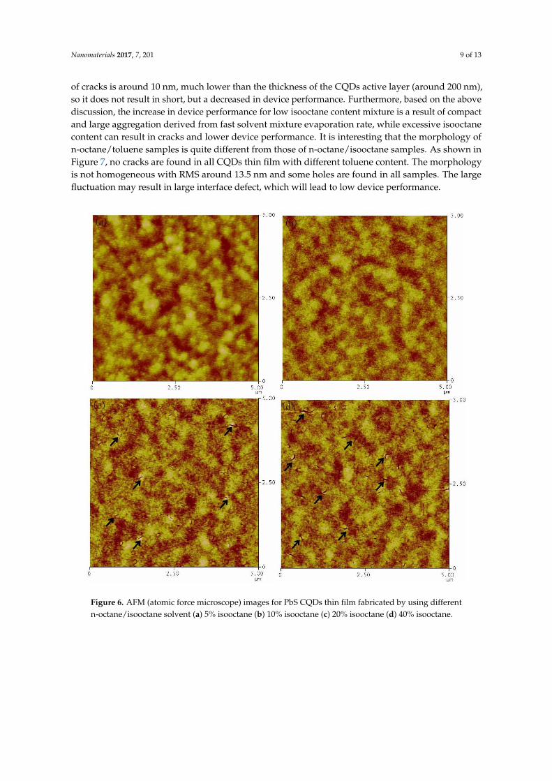
To investigate the morphology changes with different solvent contents, AFM measurement iscarried out for PbS CQDs thin film prepared by using n-octane/isooctane and n-octane/toluenemixture. As shown in Figure 6, the thin film is homogeneous and compact for all samples withroot-mean-square (RMS) value ~7.5 nm. However, the domain size is quite different in detail for thinfilms fabricated with different n-octane/isooctane content. In the case of low isooctane content, largeaggregation of PbS CQDs is found with isooctane content increase from 5 to 10% (Figure 6a,b). On thecontrary, when the isooctane content is up to 20% (60% samples have similar morphology as thatof 40% samples), a lot of cracks appear in the whole thin film (see the arrow pointing). The cracksbecome bigger with the isooctane content increase from 20 to 40%. As Au will be deposited on the PbSCQDs thin film, large cracks may result in more interface defects, which will increase interface carrierrecombination and low Jsc is expected in this case. However, it should be pointed out that the width
Nanomaterials 2017, 7, 201 9 of 13
of cracks is around 10 nm, much lower than the thickness of the CQDs active layer (around 200 nm),so it does not result in short, but a decreased in device performance. Furthermore, based on the abovediscussion, the increase in device performance for low isooctane content mixture is a result of compactand large aggregation derived from fast solvent mixture evaporation rate, while excessive isooctanecontent can result in cracks and lower device performance. It is interesting that the morphology ofn-octane/toluene samples is quite different from those of n-octane/isooctane samples. As shown inFigure 7, no cracks are found in all CQDs thin film with different toluene content. The morphologyis not homogeneous with RMS around 13.5 nm and some holes are found in all samples. The largefluctuation may result in large interface defect, which will lead to low device performance.
Nanomaterials 2017, 7, x FOR PEER REVIEW 9 of 12
width of cracks is around 10 nm, much lower than the thickness of the CQDs active layer (around 200 nm), so it does not result in short, but a decreased in device performance. Furthermore, based on the above discussion, the increase in device performance for low isooctane content mixture is a result of compact and large aggregation derived from fast solvent mixture evaporation rate, while excessive isooctane content can result in cracks and lower device performance. It is interesting that the morphology of n-octane/toluene samples is quite different from those of n-octane/isooctane samples. As shown in Figure 7, no cracks are found in all CQDs thin film with different toluene content. The morphology is not homogeneous with RMS around 13.5 nm and some holes are found in all samples. The large fluctuation may result in large interface defect, which will lead to low device performance.
Figure 6. AFM (atomic force microscope) images for PbS CQDs thin film fabricated by using different n-octane/isooctane solvent (a) 5% isooctane (b) 10% isooctane (c) 20% isooctane (d) 40% isooctane. Figure 6. AFM (atomic force microscope) images for PbS CQDs thin film fabricated by using differentn-octane/isooctane solvent (a) 5% isooctane (b) 10% isooctane (c) 20% isooctane (d) 40% isooctane.

Nanomaterials 2017, 7, 201 10 of 13
Nanomaterials 2017, 7, x FOR PEER REVIEW 10 of 12
Figure 7. AFM (atomic force microscope) images for PbS CQDs thin film fabricated by using different n-octane/toluene solvent (a) 5% toluene (b) 10% toluene (c) 20% toluene (d) 40% toluene.
4. Conclusions
In conclusion, different solvents or their hybrid are developed to fabricate PbS CQD solar cells. The device performance can be tailored by selecting different solvents or changing the solvent mixture content. In the case of single-solvent strategy, high PCE up to 6.0% is obtained in the case of n-octane or toluene devices, while PCE below 5% is obtained for isooctane, heptane or n-hexanal devices. By using hybrid solvent, the device performance can be further tailored. PCE as high as 7.64% is obtained in the case of 5% isooctane/n-octane device, which is ~15% higher than the control devices. The changes in device performance mainly originated from different solvent physical-chemical properties, which affect the morphology of final PbS CQDs thin film. We believe that if an optimized PbS CQDs film, an optimized device structure or optimized device processing technics is presented, the device performance can be further increased. Our results present an effective way to improve the performance of solution-processed PbS CQDs solar cells.
Acknowledgments: We thank the financial support of the National Natural Science Foundation of China (Nos. 91333206, 61274062 and 11204106), National Science Foundation for Distinguished Young Scholars of China (Grant No. 51225301), Guangdong Province Natural Science Fund (No. 2014A030313257) and the Fundamental Research Funds for the Central Universities.
Author Contributions: Donghuan Qin and Rongfang Wu conceived and designed the experiments; Rongfang Wu, Yuehua Yang and Miaozi Li performed the experiments; Lintao Hou and Rongfang Wu analyzed the data; Lintao Hou, Rongfang Wu, Yuehua Yang and Yangdong Zhang contributed reagents/materials/analysis tools; Donghuan Qin and Rongfang Wu wrote the paper.
Figure 7. AFM (atomic force microscope) images for PbS CQDs thin film fabricated by using differentn-octane/toluene solvent (a) 5% toluene (b) 10% toluene (c) 20% toluene (d) 40% toluene.
4. Conclusions
In conclusion, different solvents or their hybrid are developed to fabricate PbS CQD solar cells.The device performance can be tailored by selecting different solvents or changing the solvent mixturecontent. In the case of single-solvent strategy, high PCE up to 6.0% is obtained in the case of n-octane ortoluene devices, while PCE below 5% is obtained for isooctane, heptane or n-hexanal devices. By usinghybrid solvent, the device performance can be further tailored. PCE as high as 7.64% is obtained in thecase of 5% isooctane/n-octane device, which is ~15% higher than the control devices. The changesin device performance mainly originated from different solvent physical-chemical properties, whichaffect the morphology of final PbS CQDs thin film. We believe that if an optimized PbS CQDsfilm, an optimized device structure or optimized device processing technics is presented, the deviceperformance can be further increased. Our results present an effective way to improve the performanceof solution-processed PbS CQDs solar cells.
Acknowledgments: We thank the financial support of the National Natural Science Foundation of China(Nos. 91333206, 61274062 and 11204106), National Science Foundation for Distinguished Young Scholars of China(Grant No. 51225301), Guangdong Province Natural Science Fund (No. 2014A030313257) and the FundamentalResearch Funds for the Central Universities.

Nanomaterials 2017, 7, 201 11 of 13
Author Contributions: Donghuan Qin and Rongfang Wu conceived and designed the experiments; Rongfang Wu,Yuehua Yang and Miaozi Li performed the experiments; Lintao Hou and Rongfang Wu analyzed the data;Lintao Hou, Rongfang Wu, Yuehua Yang and Yangdong Zhang contributed reagents/materials/analysis tools;Donghuan Qin and Rongfang Wu wrote the paper.
Conflicts of Interest: The authors declare no conflict of interest.
References
1. Neo, D.C.J.; Cheng, C.; Stranks, S.D.; Fairclough, S.M.; Kim, J.S.; Kirkland, A.I.; Smith, J.M.; Snaith, H.J.;Assender, H.E.; Watt, A.A.R. Influence of Shell Thickness and Surface Passivation on PbS/CdS Core/ShellColloidal Quantum Dot Solar Cells. Chem. Mater. 2014, 26, 4004–4013. [CrossRef]
2. Klem, E.J.D.; Gregory, C.W.; Cunningham, G.B.; Hall, S.; Temple, D.S.; Lewis, J.S. Planar PbS quantumdot/C60 heterojunction photovoltaic devices with 5.2% power conversion efficiency. Appl. Phys. Lett. 2012,100, 173109. [CrossRef]
3. Li, M.; Liu, X.; Wen, S.; Liu, S.; Heng, J.; Qin, D.; Hou, L.; Wu, H.; Xu, W.; Huang, W.; et al. CdTe nanocrystalhetero-junction solar cells with high open circuit voltage based on Sb-doped TiO2 electron acceptor materials.Nanomaterials 2017, 7, 101. [CrossRef] [PubMed]
4. Yuan, C.; Li, L.; Huang, J.; Ning, Z.; Sun, L.; Ågren, H. Improving the Photocurrent in Quantum-Dot-Sensitized Solar Cells by Employing Alloy PbxCd1xS Quantum Dots as Photosensitizers. Nanomaterials 2016,6, 97. [CrossRef] [PubMed]
5. Panthani, M.G.; Kurley, J.M.; Crisp, R.W.; Dietz, T.C.; Ezzyat, T.; Luther, J.M.; Talapin, D.V. High EfficiencySolution Processed Sintered CdTe Nanocrystal Solar cells: The Role of interfaces. Nano Lett. 2014, 14, 670–675.[CrossRef] [PubMed]
6. Zhu, J.; Yang, Y.; Gao, Y.; Qin, D.; Wu, H.; Huang, W. Enhancement of open-circuit voltage and the fill factorin CdTe nanocrystal solar cells by using interface materials. Nanotechnology 2014, 25, 365203. [CrossRef][PubMed]
7. Tian, Y.; Zhang, Y.; Lin, Y.; Gao, K.; Zhang, Y.; Liu, K.; Yang, Q.; Zhou, X.; Qin, D.; Wu, H.; et al.Solution-processed efficient CdTe nanocrystal/CBD-CdS heterojunction solar cells with ZnO interlayer.J. Nanopart. Res. 2013, 15, 2053. [CrossRef]
8. Chen, Z.; Zhang, H.; Du, X.; Cheng, X.; Chen, X.; Jiang, Y.; Yang, B. From planar-heterojunction ton-i structure: An efficient strategy to improve short-circuit current and power conversion efficiency ofaqueous-solution-processed hybrid solar cells. Energy Environ. Sci. 2013, 6, 1597–1603. [CrossRef]
9. Chen, Z.; Zhang, H.; Li, Z.; Hao, H.; Zeng, Q.; Wang, Y.; Du, X.; Wang, L.; Yang, B. In situ construction ofnanoscale CdTe-CdS bulk heterojunctions for inorganic nanocrystal solar cells. Adv. Energy Mater. 2014, 4,1400235. [CrossRef]
10. Nir, Y.-G.; Michal, S.-H.; Marina, Z.; Shifi, K.; Asher, S.; Nir, T. Molecular control of quantum-dot internalelectric field and its application to CdSe-based solar cells. Nat. Mater. 2011, 10, 974–979.
11. Semonin, O.E.; Luther, J.M.; Choi, S.; Chen, H.Y.; Gao, J.; Nozik, A.J.; Beard, M.C. Peak External PhotocurrentQuantum Efficiency Exceeding 100% via MEG in a Quantum Dot Solar Cell. Science 2011, 334, 1530–1533.[CrossRef] [PubMed]
12. Kramer, I.J.; Levina, L.; Debnath, R.; Zhitomirsky, D.; Sargent, E.H. Solar Cells Using Quantum Funnels.Nano Lett. 2011, 11, 3701–3706. [CrossRef] [PubMed]
13. Kim, G.H.; Walker, B.; Kim, H.B.; Kim, J.Y.; Sargent, E.H.; Park, J.; Kim, J.Y. Inverted Colloidal Quantum DotSolar Cells. Adv. Mater. 2014, 26, 3321–3327. [CrossRef] [PubMed]
14. Gonfa, B.A.; Zhao, H.; Li, J.; Qiu, J.; Saidani, M.; Zhang, S.; Izquierdo, R.; Wu, N.; El Khakani, M.A.;Ma, D.; et al. Air-processed depleted bulk heterojunction solar cells based on PbS/CdS core-shell quantumdots and TiO2 nanorod arrays. Sol. Energy Mater. Sol. Cells 2014, 124, 67–74. [CrossRef]
15. Yuan, M.; Kemp, K.W.; Thon, S.M.; Kim, J.Y.; Chou, K.W.; Amassian, A.; Sargent, E.H. High-PerformanceQuantum-Dot Solids via Elemental Sulfur Synthesis. Adv. Mater. 2014, 26, 3513–3519. [CrossRef] [PubMed]
16. McDonald, S.A.; Konstantatos, G.; Zhang, S.; Paul, W.; Cyr, E.J.; Klem, D.; Levina, L.; Sargent, E.H.Solution-processed PbS quantum dot infrared photodetectors and photovoltaics. Nat. Mater. 2005, 4,138–142. [CrossRef] [PubMed]

Nanomaterials 2017, 7, 201 12 of 13
17. Lan, X.; Voznyy, O.; Arquer, F.P.G.; Liu, M.; Xu, J.; Proppe, A.H.; Walters, G.; Fan, F.; Tan, H.; Liu, M.; et al.10.6% Certified Colloidal Quantum Dot Solar Cells via Solvent-Polarity-Engineered Halide Passivation.Nano Lett. 2016, 16, 4630–4634. [CrossRef] [PubMed]
18. Ning, Z.; Ren, Y.; Hoogland, S.; Voznyy, O.; Levina, L.; Stadler, P.; Lan, X.; Zhitomirsky, D.; Sargent, E.H.All-inorganic colloidal quantum dot photovoltaics employing solution-phase-halide passivation. Adv. Mater.2012, 24, 6295–6299. [CrossRef] [PubMed]
19. Niu, G.; Wang, L.; Gao, R.; Li, W.; Guo, X.; Dong, H.; Qiu, Y. Inorganic halogen ligands in quantum dots:I-, Br-, Cl- and film fabrication through electrophoretic deposition. Phys. Chem. Chem. Phys. 2013, 15,19595–19600. [CrossRef] [PubMed]
20. Zhang, H.; Jang, J.; Liu, W.; Talapin, D.V. Colloidal nanocrystals with inorganic halide, pseudohalide, andhalometallate ligands. ACS Nano 2014, 8, 7359–7369. [CrossRef] [PubMed]
21. Dirin, D.N.; Dreyfuss, S.; Bodnarchuk, M.I.; Nedelcu, G.; Papagiorgis, P.; Itskos, G.; Kovalenko, M.V. Leadhalide perovskites and other metal halide complexes as inorganic capping ligands for colloidal nanocrystals.J. Am. Chem. Soc. 2014, 136, 6550–6553. [CrossRef] [PubMed]
22. Liu, H.; Tang, J.; Kramer, I.J.; Debnath, R.; Koleilat, G.I.; Wang, X.; Fisher, A.; Li, R.; Brzozowski, L.; Levina, L.;et al. Electron acceptor materials engineering in colloidal quantum dot solar cells. Adv. Mater. 2011, 23,3832–3837. [CrossRef] [PubMed]
23. Zhitomirsky, D.; Furukawa, M.; Tang, J.; Stadler, P.; Hoogland, S.; Voznyy, O.; Liu, H.; Sargent, E.H. N-TypeColloidal-Quantum-Dot Solids for Photovoltaics. Adv. Mater. 2012, 24, 6181–6185. [CrossRef] [PubMed]
24. Ip, A.H.; Thon, S.M.; Hoogland, S.; Voznyy, O.; Zhitomirsky, D.; Debnath, R.; Levina, L.; Amassian, A.;Sargent, E.H. Hybrid passivated colloidal quantum dot solids. Nat. Nanotechnol. 2012, 7, 577–582. [CrossRef][PubMed]
25. Chuang, C.M.; Brown, P.R.; Bulovic, V.; Bawendi, M.G. Improved performance and stability in quantum dotsolar cells through band alignment engineering. Nat. Mater. 2014, 13, 796–801. [CrossRef] [PubMed]
26. Ning, Z.; Voznyy, O.; Pan, J.; Hoogland, S.; Adinolfi, V.; Xu, J.; Li, M.; Kirmani, A.R.; Sun, J.P.; Minor, J.; et al.Air-stable n-type colloidal quantum dot solids. Nat. Mater. 2014, 13, 822–828. [CrossRef] [PubMed]
27. Kramer, I.J.; Sargent, E.H. The architecture of colloidal quantum dot solar cells: Materials to devices.Chem. Rev. 2014, 114, 863–882. [CrossRef] [PubMed]
28. Yoon, W.; Boercker, J.E.; Lumb, M.P.; Placencia, D.; Foos, E.E.; Tischler, J.G. Enhanced Open-Circuit Voltageof PbS Nanocrystal Quantum Dot Solar Cells. Sci. Rep. 2013, 3, 2225. [CrossRef] [PubMed]
29. Malgras, V.; Nattestad, A.; Yamauchi, Y.; Dou, S.X.; Kim, J.H. The effect of surface passivation on the structureof sulphur-rich PbS colloidal quantum dots for photovoltaic application. Nanoscale 2015, 7, 5706–5711.[CrossRef] [PubMed]
30. Ciach, R.; Dotsenko, Y.P.; Naumov, V.V.; Shmyryeva, A.N. Injection technique for the study of solar cell teststructures. Sol. Energy Mater. Sol. Cells 2003, 76, 613–624. [CrossRef]
31. Yang, Y.; Zhao, B.; Gao, Y.; Liu, H.; Tian, Y.; Qin, D.; Wu, H.; Hou, L.; Huang, W. Novel hybrid ligands forpassivating PbS colloidal quantum dots to enhance the performance of solar cells. Nano-Micro Lett. 2015, 7,325–331. [CrossRef]
32. Tu, Y.; Wu, J.; He, X.; Guo, P.; Wu, T.; Luo, H.; Liu, Q.; Wang, K.; Lin, J.; Huang, M.; et al. Solvent engineeringfor forming stonehenge-like PbI2 nano-structures towards efficient perovskite solar cells. J. Mater. Chem. A2017, 5, 4376–4383. [CrossRef]
33. Luo, P.; Xia, W.; Zhou, S.; Sun, L.; Cheng, J.; Xu, C.; Lu, Y. Solvent Engineering for Ambient-Air-Processed,Phase-Stable CsPbI3 in Perovskite Solar Cells. J. Phys. Chem. Lett. 2016, 7, 3603–3608. [CrossRef] [PubMed]
34. Kim, Y.J.; Jang, W.; Ahn, S.; Park, C.E.; Wang, D.H. Dramatically enhanced performances and ideallycontrolled nano-morphology via co-solvent processing in low bandgap polymer solar cells. Organ. Electron.2016, 34, 42–49. [CrossRef]
35. Chen, H.; Wei, Z.; He, H.; Zheng, X.; Wong, K.S.; Yang, S. Solvent Engineering Boosts the Efficiencyof Paintable Carbon-Based Perovskite Solar Cells to Beyond 14%. Adv. Energy Mater. 2016, 6, 1502087.[CrossRef]
36. Perumallapelli, G.R.; Vasa, S.R.; Jang, J. Improved morphology and enhanced stability via solvent engineeringfor planar heterojunction perovskite solar cells. Organ. Electron. 2016, 31, 142–148. [CrossRef]

Nanomaterials 2017, 7, 201 13 of 13
37. Wang, R.; Shang, Y.; Kanjanaboos, P.; Zhou, W.; Ning, Z.; Sargent, E.H. Colloidal quantum dot ligandengineering for high performance solar cells. Energy Environ. Sci. 2016, 9, 1130. [CrossRef]
38. Kirmani, A.R.; Carey, G.H.; Abdelsamie, M.; Yan, B.; Cha, D.; Rollny, L.R.; Cui, X.; Sargent, E.H.; Amassian, A.Effect of Solvent Environment on Colloidal-Quantum-Dot Solar-Cell Manufacturability and Performance.Adv. Mater. 2014, 26, 4717–4723. [CrossRef] [PubMed]
© 2017 by the authors. Licensee MDPI, Basel, Switzerland. This article is an open accessarticle distributed under the terms and conditions of the Creative Commons Attribution(CC BY) license (http://creativecommons.org/licenses/by/4.0/).