
Solution XT Air Handling Units Installation and Assembly (Form ...
108
SOLUTION™ XT INDOOR AND OUTDOOR UNITS SOLUTION™ AIR HANDLING UNITS INSTALLATION AND ASSEMBLY Supersedes: 102.20-N1 (615) Form 102.20-N1 (716) Issue Date: July 26, 2016 LD09624 OUTDOOR AHU (XTO) INDOOR AHU (XTI) LD17323
Transcript of Solution XT Air Handling Units Installation and Assembly (Form ...

SOLUTION™ XTINDOOR AND OUTDOOR UNITS
SOLUTION™ AIR HANDLING UNITS
INSTALLATION AND ASSEMBLY Supersedes: 102.20-N1 (615) Form 102.20-N1 (716)
Issue Date: July 26, 2016
LD09624
OUTDOOR AHU (XTO)
INDOOR AHU (XTI)
LD17323

JOHNSON CONTROLS2
FORM 102.20-N1ISSUE DATE: 7/26/2016
This equipment is a relatively complicated apparatus. During rigging, installation, operation, maintenance, or service, individuals may be exposed to certain com-ponents or conditions including, but not limited to: heavy objects, refrigerants, materials under pressure, rotating components, and both high and low voltage. Each of these items has the potential, if misused or handled improperly, to cause bodily injury or death. It is the obligation and responsibility of rigging, instal-lation, and operating/service personnel to identify and recognize these inherent hazards, protect themselves, and proceed safely in completing their tasks. Failure to comply with any of these requirements could result in serious damage to the equipment and the property in
IMPORTANT!READ BEFORE PROCEEDING!
GENERAL SAFETY GUIDELINES
which it is situated, as well as severe personal injury or death to themselves and people at the site.
This document is intended for use by owner-authorized rigging, installation, and operating/service personnel. It is expected that these individuals possess independent training that will enable them to perform their assigned tasks properly and safely. It is essential that, prior to performing any task on this equipment, this individual shall have read and understood the on-prooduct labels, this document, and any referenced materials. This in-dividual shall also be familiar with and comply with all applicable industry and governmental standards and regulations pertaining to the task in question.
SAFETY SYMBOLSThe following symbols are used in this document to alert the reader to specific situations:
Indicates a possible hazardous situation which will result in death or serious injury if proper care is not taken.
Indicates a potentially hazardous situa-tion which will result in possible injuries or damage to equipment if proper care is not taken.
Identifies a hazard which could lead to damage to the machine, damage to other equipment and/or environmental pollu-tion if proper care is not taken or instruc-tions and are not followed.
Highlights additional information useful to the technician in completing the work being performed properly.
External wiring, unless specified as an optional connection in the manufacturer’s product line, is not to be connected inside the control cabinet. Devices such as relays, switches, transducers and controls and any external wiring must not be installed inside the micro panel. All wiring must be in accor-dance with Johnson Controls’ published specifications and must be performed only by a qualified electrician. Johnson Controls will NOT be responsible for damage/problems resulting from improper connections to the controls or application of improper control signals. Failure to follow this warn-ing will void the manufacturer’s warranty and cause serious damage to property or personal injury.

JOHNSON CONTROLS 3
FORM 102.20-N1 ISSUE DATE: 7/26/2016
MANUAL DESCRIPTION FORM NUMBER
York Air Handling Units Operation and Maintenance 102.20-OM1
Steps to Protect New Equipment Warranty 102.20-CL1
Air Handling Units Start-up Checklist 100.00-CL1
Long-Term Storage Requirement - Field Preparation - Air Handling Units 50.05-NM3
Long-Term Storage Periodic Checklist and Logs - Air Handling Units 50.20-CL3
Limited Warranty 50.05-NM2
Electric Motor Warranty 50.05-NM2.2
Air Cooled Condensing Unit DX Coil Split System Applications and Piping Guidelines 50.40-ES3
Air Modulator Service & Warranty Procedure SI0262
CHANGEABILITY OF THIS DOCUMENT
In complying with Johnson Controls’ policy for con-tinuous product improvement, the information con-tained in this document is subject to change without notice. Johnson Controls makes no commitment to update or provide current information automatically to the manual or product owner. Updated manuals, if applicable, can be obtained by contacting the nearest Johnson Controls Service office or accessing the John-son Controls QuickLIT website at http://cgproducts.johnsoncontrols.com.
It is the responsibility of rigging, installation, and op-erating/service personnel to verify the applicability of these documents to the equipment. If there is any ques-
tion regarding the applicability of these documents, rigging, lifting, and operating/service personnel should verify whether the equipment has been modified and if current literature is available from the owner of the equipment prior to performing any work on the unit.
CHANGE BARSRevisions made to this document are indicated with a line along the left or right hand column in the area the revision was made. These revisions are to technical in-formation and any other changes in spelling, grammar or formatting are not included.
ASSOCIATED LITERATURE

JOHNSON CONTROLS4
FORM 102.20-N1ISSUE DATE: 7/26/2016
SOLUTION XT UNIT MODEL NOMENCLATURE
XT
PRIMARY IDENTIFIERXT
ENVIRONMENTI=IndoorO=Outdoor
I
NOMINAL HEIGHT27 to 132
NOMINAL WIDTH27 to 288
075048 x D
SUPPLY AND RETURN/EXHAUST FAN OPTIONSA=NoneB=DWDI FC Fan without Motor ControllerC=DWDI FC Fan with Service Disconnect OnlyD=DWDI FC Fan with Motor StarterE=DWDI FC Fan with Variable Frequency Drive (VFD)F=DWDI AF Fan without Motor ControllerG=DWDI AF Fan with Service Disconnect OnlyH=DWDI AF Fan with Motor StarterJ=DWDI AF Fan with VFDK=SWSI PL Fan without Motor ControllerL=SWSI PL Fan with Service Disconnect onlyM=SWSI PL Fan with Motor StarterN=SWSI PL Fan with VFDP=SWSI PL Fan Direct Drive without Motor Controller Q=SWSI PL Fan Direct Drive with Service Disconnect OnlyR=SWSI PL Fan Direct Drivee with Motor StarterS=SWSI PL Fan Direct Drive with VFD
C
FACTORY MOUNTED END DEVICES0=No1=Yes
0 46M
MOTOR HORSEPOWERSUPPLY AND RETURN/EXHAUST FANA=0B=1/2C=3/4D=1E=1 1/2F=2G=3H=5J=7 1/2K=10L=15M=20N=25P=60Q=40R=50S=60T=75U=100V=125
KVOLTAGE CODE12=120-1-6017=200 or 208-3-6027=277-1-6028=230 or 240-3-6040=360-3-6044=440-3-5046=460-3-6050=380 or 415-3-5058=575-3-6063=220-3-50
A
DESIGNA=Original Unit Design
Note: The terms skid and section have the same meaning in this document; Variable Speed Drive (VSD) and Variable Frequency Drive (VFD) do as well.

JOHNSON CONTROLS 5
FORM 102.20-N1 ISSUE DATE: 7/26/2016
TABLE OF CONTENTS
SECTION 1 - GENERAL INFORMATION AND SAFETY .......................................................................................13Introduction .....................................................................................................................................................13Warranty .........................................................................................................................................................13Responsibility for Safety .................................................................................................................................13
SECTION 2 - PRODUCT DESCRIPTION ...............................................................................................................15Typical Solution Operation .............................................................................................................................15
Ventilation System .................................................................................................................................15Economizer System (Typical) ................................................................................................................15Heating and Cooling System .................................................................................................................16
Cleaning .........................................................................................................................................................16Hand Orientation ............................................................................................................................................16AHU Identification (ID) ....................................................................................................................................16
AHU ID Label ........................................................................................................................................17Skid ID Label .........................................................................................................................................17Segment ID Box ....................................................................................................................................17Shipped Loose Parts .............................................................................................................................19
Direction of Airflow ..........................................................................................................................................19
SECTION 3 - HANDLING, STORAGE, AND INSTALLATION ...............................................................................21Delivery and Storage ......................................................................................................................................21
Short Term .............................................................................................................................................21Long Term .............................................................................................................................................22
Inspection, Damage, and Shortage ...............................................................................................................22Check Solution XT Doors and Latches .................................................................................................23Indoor AHUs ..........................................................................................................................................23Outdoor AHUs .......................................................................................................................................23Shipped Loose Parts .............................................................................................................................23
Lifting Weights ................................................................................................................................................23Moving the AHU .............................................................................................................................................23Rigging ...........................................................................................................................................................23Using Fork Lift in Special Circumstances .......................................................................................................24Come-A-Longs (Power Pulls) .........................................................................................................................24Proper Lifting with Shackles ..........................................................................................................................24Preparing the Site ...........................................................................................................................................25
Clearance for Outdoor AHUs .................................................................................................................25Assembling the Johnson Controls Provided Curb .................................................................................26Clearance and Mounting for Indoor AHUs .............................................................................................28Installing Ceiling Suspended AHUs .......................................................................................................29
Tools Required to Install AHU .........................................................................................................................30Shipped Loose Parts ......................................................................................................................................30
Pipe Chase, Hoods and Seam Caps .....................................................................................................31Additional Parts .....................................................................................................................................33
Installing Outdoor AHU ...................................................................................................................................34Single Piece Outdoor AHU ....................................................................................................................34Multi-Piece Outdoor Solution XT AHU ...................................................................................................34Setting Up the Sections ........................................................................................................................36Pulling the Solution XT Sections Together ............................................................................................37
Installing Indoor Solution XT AHU ..................................................................................................................39

JOHNSON CONTROLS6
FORM 102.20-N1ISSUE DATE: 7/26/2016
TABLE OF CONTENTS (CONT'D)
Setting Up and Pulling Solution XT Sections Together .........................................................................41Installing a Tiered AHU ..........................................................................................................................43Assembling the Solution XT End Channel Shipping Split .....................................................................45Installing Hood with Moisture Eliminators ..............................................................................................47Outdoor Air Temperature and/or Humidity Sensors ...............................................................................47Installing Damper Actuator ....................................................................................................................48Installing Multi-Zone (MZ) Dampers ......................................................................................................49Installing Field Supplied MZ Damper Actuators ...................................................................................50
Back Draft Dampers for Dual Fans and Fan Arrays ......................................................................................50Filling Inertia Fan Base ..................................................................................................................................51Steam Humidifier ............................................................................................................................................51UVC Emitter Lamps ........................................................................................................................................51
Two Types of Lamps .............................................................................................................................51Air Measuring Device Connections ...............................................................................................................56
Air Measuring at the Fan Inlets .............................................................................................................56Air Measuring at Unit Outside Air Inlets .................................................................................................56
Installing the Pipe Chase ................................................................................................................................57Tools and Materials ...............................................................................................................................57Preparing Pipe Chase for Installation ....................................................................................................57Apply Gaskets .......................................................................................................................................57Attach Pipe Chase .................................................................................................................................58Seal Pipe Chase to Solution XT AHU ....................................................................................................59Install Cover Angles ...............................................................................................................................59Install Base Rail Covers (If Applicable) .................................................................................................60
Installing External Vent Piping for Outdoor AHUS ..........................................................................................61Condensate Drain Arrangement ............................................................................................................61
Field Penetrations for Piping and Electrical Connections ...............................................................................63Tools Required ......................................................................................................................................63Material Required ..................................................................................................................................63Procedure ..............................................................................................................................................63
General Electrical Information ........................................................................................................................65Power Connections ........................................................................................................................................65
Single Point Power ................................................................................................................................65Motors for Supply, Return, and Exhaust Fans .......................................................................................66
Wiring the Energy Recovery Wheel ...............................................................................................................66Wiring the Gas Heat Device ...........................................................................................................................67Wiring the Electric Heat Device ......................................................................................................................68
Power Options .......................................................................................................................................68Disconnect Switch Options ....................................................................................................................68Control Options .....................................................................................................................................69Installing Electrical Heat Option ............................................................................................................69
Electric Humidifier ..........................................................................................................................................72Humidifier .......................................................................................................................................................72Lights for Solution XT AHUs ...........................................................................................................................73Piping Connections ........................................................................................................................................73Coil Piping ......................................................................................................................................................74
Staggered Coils .....................................................................................................................................74Hot and Chilled Water Coils ..................................................................................................................75
Water Treatment .............................................................................................................................................77

JOHNSON CONTROLS 7
FORM 102.20-N1 ISSUE DATE: 7/26/2016
Vertical Tube Integral Face and Bypass (VIFB) and Integral Face and Bypass (IFB) ....................................79Shipping Bolts (VIFB Only) ....................................................................................................................79Piping Suggestions ...............................................................................................................................79Flexible Connectors (VIFB Only) ...........................................................................................................79Freezing Conditions ..............................................................................................................................79
Refrigeration ...................................................................................................................................................83DX Direct Expansion Coils ....................................................................................................................83Available Coil Arrangements ................................................................................................................85
Thermostatic Expansion Valves (TXV) ..........................................................................................................87Hot Gas Bypass (HGBP) ................................................................................................................................87Dx Coil Circuiting and Staging ........................................................................................................................87
Advantages of Multiple Control Stages .................................................................................................88Maintaining Adequate Airflow .......................................................................................................................88VAV Systems ..................................................................................................................................................89Drains and Traps ............................................................................................................................................89
Condensate Drain Piping ......................................................................................................................89Elevating AHU for Gravity Floor Drain Connections ..............................................................................90
Duct Connections ...........................................................................................................................................91Duct Connection Guidelines ..................................................................................................................91Flanged Duct or Sleeves .......................................................................................................................91Raw or Straight Edge Duct or Sleeves ..................................................................................................91Sound and Vibration Transmission .......................................................................................................92Installing Top Discharge Outdoor AHU Duct .........................................................................................92Installing Front and Rear Discharge Outdoor AHU Duct .......................................................................92
Air Filters ........................................................................................................................................................94Maintaining and Replacing Filters .........................................................................................................94Filter Installation Installing a 2 in. Pleated Filter ...............................................................................................................98Installing a 4 in. Pleated Filter ...............................................................................................................98Installing a Single Headered (SH) Filter ................................................................................................99Installing a 2 in. Pre-Filter Combined with a SH Final Filter ..................................................................99Installing a Multi-Cell SBM Double Headered (DH) Filter ....................................................................100Installing a 2 in. and 4 in. Pre-Filter Combined with a DH Final Filter .................................................101
Hepa Filters ..................................................................................................................................................103Koch HEPA Filter Frame .....................................................................................................................103Welded Bevel Seal Frame ...................................................................................................................104
Visual Control Filter Clamps .........................................................................................................................104HEPA Filter Applications ......................................................................................................................104
Temperature .................................................................................................................................................107
TABLE OF CONTENTS (CONT'D)

JOHNSON CONTROLS8
FORM 102.20-N1ISSUE DATE: 7/26/2016SOLUTION XT UNIT MODEL NOMENCLATURE
LIST OF FIGURES
FIGURE 1 - Cutaway of Solution XT Showing Segmented Construction ................................................................15FIGURE 2 - AHU and Coil Hand Identification ........................................................................................................16FIGURE 3 - AHU ID Label .......................................................................................................................................17FIGURE 4 - Skid ID Label .......................................................................................................................................17FIGURE 5 - Example of Segment Id Box ................................................................................................................17FIGURE 6 - Example of Moisture Eliminator Loose Component ID Label ..............................................................19FIGURE 7 - Example of Hood Loose Component ID Label ....................................................................................19FIGURE 8 - Filter ID Label ......................................................................................................................................19FIGURE 9 - Metal Spacers on Solution XT Doors ...................................................................................................23FIGURE 10 - Recommended Lifting with Multiple Points ........................................................................................24FIGURE 11 - Typical Come-A-Longs .......................................................................................................................24FIGURE 12 - Proper Lifting with Shackle with Corner Connector Corners .............................................................24FIGURE 13 - Proper Lifting with Shackle at Lifting Lug...........................................................................................25FIGURE 14 - Proper Lifting with Base Rail..............................................................................................................25FIGURE 15 - Minimum Service Clearances ............................................................................................................26FIGURE 16 - Typical Curb Assembly ......................................................................................................................27FIGURE 17 - Solution XT No Base Rail - Housekeeping Pad Required to Accomodate Trap Height .....................28FIGURE 18 - No Housekeeping Pad - Solution XT Base Rail Required to Accomodate Trap Height .....................28FIGURE 19 - With Base or Base Rail and Housekeeping Pad ...............................................................................28FIGURE 20 - Ceiling Suspended AHU on Structural Steel......................................................................................29FIGURE 21 - Tools Needed to Assemble Shipping Splits .......................................................................................30FIGURE 22 - Second Tier Tie-Down Fastener Pack (P/N 386-03419-000) ............................................................30FIGURE 23 - Bottom Raceway Shipping Split Fastener Pack (P/N 386-03418-000)..............................................31FIGURE 24 - Base Rail Shipping Split Fastener Pack (P/N 386-03417-000) .........................................................31FIGURE 25 - Top Raceway Bracket Assembled (P/N 386-04747-000) ...................................................................31FIGURE 26 - Neoprene Gasket - 1/4 In. X 2 In. X 25 Ft (P/N 028-11883-010) .......................................................31FIGURE 27 - Neoprene Gray Gasket - 1/4 In X 3/4 In X 35 Ft (P/N 028-11873-010) for Door ..............................31FIGURE 28 - Phillips Hex Head Screw (P/N 021-32268-011) For Indoor Unit Seam Cap ......................................31FIGURE 29 - Hex Head Screw For Outdoor Roof Seam Cap, Pipe Chase, and Rain Hood - 1/4 In-14 X 1 In (P/N
021-30530-052) .................................................................................................................................32FIGURE 30 - Butyl Tape - 3/16 In X 3/4 In X 40 Ft (P/N 013E-03327-010) .............................................................32FIGURE 31 - Polyurethanecaulk (P/N 021-19568-000 - Grey; P/N 013-03317-040 - Champagne) For
Pipe Chase Only ................................................................................................................................32FIGURE 32 - Roof Seam Cap (Assembled) ............................................................................................................32FIGURE 33 - Pipe Chase, Trim Angle, and Cover...................................................................................................32FIGURE 34 - Hood ..................................................................................................................................................33FIGURE 35 - Damper Shaft Extension Kit (P/N 026-33715-002) ............................................................................33FIGURE 36 - Corner Connector Hole Plug (P/N 021-19568-000) (8) .....................................................................33FIGURE 37 - Touch-Up Spray - 12 Oz. (P/N 013-03322-000) ................................................................................33FIGURE 38 - Shipping Split Corner Gasket - 3.5 X 3. 5 (P/N 028-11883-010) ......................................................33FIGURE 39 - Spare Fan Belt ...................................................................................................................................33FIGURE 40 - Conduit (P/N 025-39024-001) and SJO Cord (P/N 025-35746-001) .................................................33FIGURE 41 - Shipping Split Examples ....................................................................................................................35FIGURE 42 - Shipping Split Examples Using Structural Steel Baserails ................................................................35FIGURE 43 - Applying Gasket Square, Neoprene Gasket and Caulk to Raceway Split .........................................36FIGURE 44 - Typical Come-A-Longs ......................................................................................................................36FIGURE 45 - Electrical Connector (Not Connected) ...............................................................................................36

JOHNSON CONTROLS 9
SOLUTION XT UNIT MODEL NOMENCLATURE FORM 102.20-N1 ISSUE DATE: 7/26/2016
LIST OF FIGURES (CONT'D)
FIGURE 46 - Electrical Connectors (Connected) .................................................................................................... 37FIGURE 47 - Remove and Reposition Shipping Split Angle ................................................................................... 37FIGURE 48 - Come-A-Long Attached to a Section ................................................................................................. 37FIGURE 49 - Bring Shipping Splits Together ........................................................................................................... 37FIGURE 50 - Applying Caulk to Seams ................................................................................................................... 38FIGURE 51 - Installing Gaskets .............................................................................................................................. 38FIGURE 52 - Solution XT Corner Connector Hole Plug (P/N 021-19568-000) ....................................................... 38FIGURE 53 - Use Gasket (P/N 028-11883-010) at Shipping Split .......................................................................... 39FIGURE 54 - Use Gasket (P/N 028-11873-010) to Door Frame at Shipping Split .................................................. 39FIGURE 55 - Assembly of End Channel Shipping Split with a Solution XT Expanded Cabinet .............................. 40FIGURE 56 - Come-A-Long Attached to a Section ................................................................................................. 41FIGURE 57 - Remove Lifting Lugs in Expanded Cabinet........................................................................................ 41FIGURE 58 - Electrical Connector (Not Connected) ............................................................................................... 41FIGURE 59 - Electrical Connectors (Connected) .................................................................................................... 41FIGURE 60 - Remove and Reposition Shipping Split Angle ................................................................................... 42FIGURE 61 - Bring Shipping Splits Together ........................................................................................................... 42FIGURE 62 - Fasten Bottom Lifting Lugs ................................................................................................................ 43FIGURE 63 - Installing Gaskets .............................................................................................................................. 43FIGURE 64 - Solution XT Corner Connector Hole Plug (P/N 021-19568-000) ....................................................... 43FIGURE 65 - Tiered Solution XT AHU ..................................................................................................................... 43FIGURE 66 - Second Tier Tie-Down Fastener Pack (P/N 386-03419-000) ............................................................ 44FIGURE 67 - Apply Gaskets to Top Panel on Bottom Tier ...................................................................................... 44FIGURE 68 - Guide Brackets Together ................................................................................................................... 44FIGURE 69 - Solution XT Lights Tier Transition Drawing ........................................................................................ 45FIGURE 70 - Assembling the End Channel Shipping Split with Energy Recovery Wheel ...................................... 46FIGURE 71 - Installing Hood with Optional Moisture Eliminators............................................................................ 47FIGURE 72 - Installing the Direct Coupled Actuator................................................................................................ 48FIGURE 73 - Installing MZ Damper......................................................................................................................... 49FIGURE 74 - Damper Shaft Extension Kit (P/N 026-33715-002) ............................................................................ 50FIGURE 75 - Counterbalance Locked Into Place for Shipping................................................................................ 50FIGURE 76 - Counterbalance Unlocked for Start-Up .............................................................................................. 50FIGURE 77 - V-Max Grid Lamps ............................................................................................................................. 51FIGURE 78 - Installing V-Mod Lamp ....................................................................................................................... 51FIGURE 79 - Installing V-Max Grid Lamps .............................................................................................................. 51FIGURE 80 - UV Control Panel Wiring (8 amps)..................................................................................................... 53FIGURE 81 - UV Control Panel Wiring (Greater than 8 amps) ............................................................................... 54FIGURE 82 - High and Low Connections for an in Fan Air Monitoring System....................................................... 56FIGURE 83 - High and Low Connections and Associated Tubing for Fan Mounted Air Monitoring System ........... 56FIGURE 84 - Port Locations for Fan Mounted Air Monitoring System .................................................................... 56FIGURE 85 - Install Gasket Under Roof Overhang ................................................................................................. 57FIGURE 86 - Apply Gasket to Pipe Chase .............................................................................................................. 58FIGURE 87 - Install Pipe Chase Base Rail to AHU Base Rail................................................................................. 58FIGURE 88 - Install Flanges.................................................................................................................................... 58FIGURE 89 - Apply Caulk to Solution XT Base Rail ................................................................................................ 59FIGURE 90 - Apply Caulk Between Pipe Chase and Solution XT AHU .................................................................. 59FIGURE 91 - Install Pipe Chase to Solution XT Roof .............................................................................................. 59FIGURE 92 - Install Cover Angle ............................................................................................................................. 59

JOHNSON CONTROLS10
FORM 102.20-N1ISSUE DATE: 7/26/2016SOLUTION XT UNIT MODEL NOMENCLATURE
LIST OF FIGURES (CONT'D)
FIGURE 93 - Position Cover Angle Properly ........................................................................................................... 60FIGURE 94 - Properly Install Screws ...................................................................................................................... 60FIGURE 95 - Apply Solution XT Base Rail Cover ................................................................................................... 60FIGURE 96 - Gas Furnace Fuel Venting System .................................................................................................... 61FIGURE 97 - Gas Furnace Condensate Drain Trap ................................................................................................ 62FIGURE 98 - Penetrations and Grommet Details................................................................................................... 64FIGURE 99 - Single Point Power Connection ......................................................................................................... 65FIGURE 100 - Typical Motor Data/Name Plate ....................................................................................................... 66FIGURE 101 - Another Typical Motor Data/Name Plate .......................................................................................... 66FIGURE 102 - Access Electrical Box....................................................................................................................... 66FIGURE 103 - Typical Power Wiring of Energy Recovery Wheel ........................................................................... 67FIGURE 104 - Gas Burner Component Locations .................................................................................................. 67FIGURE 105 - Main Power and Control Panel with Cover Open ............................................................................ 67FIGURE 106 - Typical Electrical Heat Control Panel Interior Wiring and Components ........................................... 68FIGURE 107 - Typical Field and Power Connections .............................................................................................. 68FIGURE 108 - Pressure Probe Direction................................................................................................................. 70FIGURE 109 - Air Flow Switch Connections ........................................................................................................... 70FIGURE 110 - Layout of Typical Humidifier Panel ................................................................................................... 72FIGURE 111 - Supply Power Knockouts ................................................................................................................. 72FIGURE 112 - Humidifier Points .............................................................................................................................. 72FIGURE 113 - Solution XT AHU with Lights Tier Transition Drawing ...................................................................... 73FIGURE 114 - Solution XT Pipe Chase Enclosure .................................................................................................. 73FIGURE 115 - Factory Coil Connections ................................................................................................................. 74FIGURE 116 - Staggered Coil - Angled Wall ........................................................................................................... 74FIGURE 117 - Split Coil - Opposite Side Connections ............................................................................................ 74FIGURE 118 - Chilled Water Coil Connections Example - (Not for Construction) ................................................... 75FIGURE 119 - Hot Water Piping with 2-Way Valve Example (Not for Construction) ............................................... 76FIGURE 120 - Hot Water Piping with Diverting Valve Example (Not for Construction) ........................................... 76FIGURE 121 - Steam Coil Piping Arrangements ..................................................................................................... 78FIGURE 122 - IFB Coil (Horizontal Tubes Available with Steam and Hot Water) ................................................... 80FIGURE 123 - VIFB Coil (Face-Mounted Actuator Shown) ..................................................................................... 80FIGURE 124 - Hot Water Piping Schematic for 2-Row Coil VIFB ........................................................................... 80FIGURE 125 - Hot Water Piping for IFB .................................................................................................................. 81FIGURE 126 - Steam Piping for VIFB ..................................................................................................................... 82FIGURE 127 - Typical Piping and Sundries at the DX Coil ..................................................................................... 84FIGURE 128 - DX Coil Circuiting Types .................................................................................................................. 84FIGURE 129 - Non-Stacked Coil Design (Special Quote)....................................................................................... 85FIGURE 130 - Non-Stacked Coil Design (Standard)............................................................................................... 85FIGURE 131 - Stacked Coil Design (Standard) ...................................................................................................... 86FIGURE 132 - Stack Coil Designs (Special Quote)................................................................................................. 86FIGURE 133 - Stacked Coil Circuiting..................................................................................................................... 87FIGURE 134 - One Coil Circuit Per Refrigerant Circuit ........................................................................................... 87FIGURE 135 - Two Coil Circuit Per Refrigerant Circuit ........................................................................................... 87FIGURE 136 - Three Compressor Unit ................................................................................................................... 88FIGURE 137 - Six Compressor Unit ........................................................................................................................ 88FIGURE 138 - Drain Trap Showing Water Location for Draw Through Operation .................................................. 90FIGURE 139 - Trap Detail for Drain Pan in Negative Environment (Draw Through) ............................................... 90
JOHNSON CONTROLS 11
SOLUTION XT UNIT MODEL NOMENCLATURE FORM 102.20-N1 ISSUE DATE: 7/26/2016
LIST OF TABLES
TABLE 1 - Definition of Segment IDS .....................................................................................................................18TABLE 2 - TSP and Drain Trap ...............................................................................................................................62TABLE 3 - Maximum Current ..................................................................................................................................71TABLE 4 - Koch Filter Clips - Single Filter Application ............................................................................................96TABLE 5 - Koch Filter Clips - Pre-Filter / Final Filter Application ............................................................................96TABLE 6 - AAF Clips for Filter Frames - Single Filter Application ...........................................................................97TABLE 7 - AAF Pre-Filter/Final Filter Application ...................................................................................................97TABLE 8 - Visual Control Filter Clamps for HEPA Filters .....................................................................................105TABLE 9 - SI Metric Conversion ...........................................................................................................................107
FIGURE 140 - Trap Detail for Drain Pan in Positive Environment (Blow Through) .................................................90FIGURE 141 - Combining Drain Lines ....................................................................................................................90FIGURE 142 - Recommended Discharge Duct Arrangement when Turns are Required ........................................91FIGURE 143 - Duct Arrangement for Flange and Raw Edge Ducts ........................................................................92FIGURE 144 - Duct Penetration of Roof .................................................................................................................93FIGURE 145 - Roof to Duct Installation (Horizontal Discharge) ..............................................................................93FIGURE 146 - Typical Filter Types ..........................................................................................................................94FIGURE 147 - Filter Latches ...................................................................................................................................95FIGURE 148 - Correctly Installed Latch Pin (P/N 026-35788-702) .........................................................................98FIGURE 149 - Fully Installed Filter ..........................................................................................................................98FIGURE 150 - Correctly Installed Latch Pin (P/N 026-35788-604) .........................................................................98FIGURE 151 - Place the End of the Latch Over the Filter Frame ...........................................................................99FIGURE 152 - Correctly Installed Cartridge Filter ...................................................................................................99FIGURE 153 - Correctly Installed Latch Pin (P/N 026-35788-604) .......................................................................100FIGURE 154 - Correctly Installed Cartridge with Pleats ........................................................................................100FIGURE 155 - Correct use of Knockouts ..............................................................................................................100FIGURE 156 - Correct Latchout/Knockout Configuration ......................................................................................100FIGURE 157 - Frame with Four Latches Installed on the Sides............................................................................101FIGURE 158 - Spring Latch Pulled and Fastened in Filter Hole ...........................................................................101FIGURE 159 - Correct Latchout/Knockout Configuration (P/N 026-35788-612) ...................................................101FIGURE 160 - Spring Latch Pulled and Fastened in Filter Hole ...........................................................................102FIGURE 161 - Installing Pre-Filter Latch ...............................................................................................................102FIGURE 162 - Position Pre-Filter in Front of Final Filter .......................................................................................102FIGURE 163 - Spring End of Latch .......................................................................................................................102FIGURE 164 - Completed Assembly .....................................................................................................................102FIGURE 165 - Installation of Koch HEPA Filters ...................................................................................................103FIGURE 166 - Koch HF .........................................................................................................................................104FIGURE 167 - Hepa Filter (Cross Section) ...........................................................................................................104FIGURE 168 - Visual Control Filter Clamps ..........................................................................................................105FIGURE 169 - Installing Hepa Filter ......................................................................................................................105FIGURE 170 - Installing Welded Bevel Seal Filter ................................................................................................106
LIST OF FIGURES (CONT'D)

JOHNSON CONTROLS12
FORM 102.20-N1ISSUE DATE: 7/26/2016SERVICE TASK REFERENCE
SERVICE TASK REFERENCE
Air Filters 94 Installing a 2 in. Pleated Filter 98 Installing a 4 in. Pleated Filter 98 Installing a Single Headered (SH) Filter 99 Installing a 2 in. Pre-Filter Combined with a SH Final Filter 99 Installing a Multi-Cell SBM Double Headered (DH) Filter 100 Installing a 2 in. and 4 in. Pre-Filter Combined with a DH Final Filter 101Air Measuring Device Connections 56
Assembling the Solution XT End Channel Shipping Split 45Assembling the Johnson Controls Provided Curb 26Clearance and Mounting for Indoor AHUs 28
Coil Piping 74Staggered Coils 74Hot and Chilled Water Coils 75Water Treatment 77Condensate Drain Arrangement 61
Drains and Traps 89Condensate Drain Piping 89Elevating AHU for Gravity Floor Drain Connections 90Duct Connections 91Duct Connection Guidelines 91Flanged Duct or Sleeves 91Raw or Straight Edge Duct or Sleeves 91Sound and Vibration Transmission 92General Electrical Information 65
HEPA Filters 103
Hot Gas Bypass (HGBP) 87
Inspection, Damage, and Shortage 22Receiver's Responsibility 23Shipped Loose Parts 23Installing Ceiling Suspended AHUs 29
Installing Damper Actuator 48Installing Multi-Zone (MZ) Dampers 51Installing Field Supplied MZ Damper Actuators 52Installing External Vent Piping for Outdoor AHUs 61
Installing Hood with Moisture Eliminator 49
Installing Indoor Solution XT AHU 39Installing an Solution XT AHU with Expanded Cabinet 39Installing Outdoor AHU 36Single Piece 36Multi-Piece 36Installing Pipe Chase 57Tools and Materials 57Apply Gaskets 57Attach the Pipe Chase 58 Install Cover Angles 59 Install Base Rail Covers 60 Installing Tiered AHU 43
Long Term Storage 22
Piping Connections 73
Power Connections 65Single Point Power 65Wiring the Gas Heat Device 67Wiring the Electric Heat Device 68Electric Humidifier 72Humidifier 72Lights for Solution XT AHUs 73Preparing the Site 25
Proper Lifting with Shackles 24
Refrigeration 83DX Direct Expansion Coils 83Available Coil Arrangements 85Rigging 23Indoor and Outdoor AHUs 23Shipped Loose Parts 23Short Term Storage 23Thermostatic Expansion Valves (TXV) 87Tools Required to Install AHU 32UVC Emitter Lamps 51Two Types of Lamps 51VAV System 89VIFB and IFB 79Shipping Bolts 79Visual Control Filter Clamps 104

JOHNSON CONTROLS 13
FORM 102.20-N1 ISSUE DATE: 7/26/2016
1SECTION 1 - GENERAL INFORMATION AND SAFETY
INTRODUCTIONThe air handling unit (AHU) is manufactured to the highest design and construction standards to ensure high performance, reliability and adaptability to all types of air handling installations.
This manual and any other document supplied with the AHU are the property of Johnson Controls, which re-serves all rights. This manual may not be reproduced, in whole or in part, without prior written authorization from an authorized Johnson Controls representative.
In addition, this manual:
• Includes suggested best working practices and procedures, which are issued for guidance only, and they do not take precedence over the above stated individual responsibility and/or local safety regulations.
• Contains all the information required for correct installation and commissioning of the AHU, to-gether with operating and maintenance instruc-tions.
• Should be read thoroughly before attempting to operate or service the AHU.
• Contains detailed procedures, including installa-tion, commissioning and maintenance tasks that must only be performed by suitably trained and qualifiedpersonnel.
Rigging and lifting should only be done by a profes-sional rigger in accordance with a written rigging and lifting plan. The most appropriate rigging and lifting method will depend on job specific factors, such as the rigging equipment available and site needs. Therefore, a professional rigger must determine the rigging and lifting method to be used, and it is beyond the scope of this manual to specify rigging and lifting details.
The manufacturer will not be liable for any injury or damage caused by incorrect installation, commission-ing, operation, or maintenance resulting from a failure to follow the procedures and instructions detailed in the manual.
WARRANTYJohnson Controls warrants AHUs in accordance with the Limited Warranty Engineered Systems Equipment procedure. Refer to the Standard Limited Warranty
Engineered Systems Equipment (Form 50.05-NM2) for more information.
Johnson Controls warrants all equipment and materi-als against defects in workmanship and materials for a period of 18 months from the date of shipment or 12 months from the date of start-up, whichever comes first, unless labor or extended warranty has been pur-chased as part of the contract.
The warranty is limited to parts only replacement and shipping of any faulty part, or subassembly, which has failed due to defects in workmanship and materials. All claims must be supported by evidence that the failure has occurred within the warranty period, and that the AHU was operated within the designed parameters specified.
All warranty claims must specify the AHU model, se-rial number, order number, and run hours/starts. Model and serial number information is printed on the AHU identification plate.
The AHU warranty will be void if any modification to the AHU is carried out without prior written approval from Johnson Controls. For warranty purposes, the fol-lowing conditions must be satisfied:
• Only genuine YORK approved spare parts must be used.
• All of the scheduled maintenance operations de-tailed in this manual must be performed at the specified timesby suitably trained andqualifiedpersonnel.
• Failure to satisfy any of these conditions will au-tomatically void the warranty. Refer to Standard Limited Warranty Engineered Systems Equipment (Form 50.05-NM2) for details.
RESPONSIBILITY FOR SAFETYEvery care has been taken in the design and manufac-ture of the AHU to ensure compliance with the safety requirements. However, the individual operating or working on any equipment is primarily responsible for:
• Personal safety, safety of other personnel, and the equipment.
• Correct utilization of the equipment in accordance with the procedures detailed in this manual.

JOHNSON CONTROLS14
FORM 102.20-N1ISSUE DATE: 7/26/2016SECTION 1 - GENERAL INFORMATION AND SAFETY
THIS PAGE INTENTIONALLY LEFT BLANK.

JOHNSON CONTROLS 15
FORM 102.20-N1 ISSUE DATE: 7/26/2016
2
SECTION 2 - PRODUCT DESCRIPTION
Ventilation SystemThe purpose of a ventilation system is to remove air that is substandard to creature comfort or a process, and replace it with suitable air. Depending on the ap-plication, the system will operate at various specified rates, volumes, and conditions. A ventilation system may employ an AHU with a supply fan working in conjunction with a remote exhaust fan(s). A more ef-fective method would employ a supply fan and an ex-haust fan in the AHU.
Economizer System (Typical)The economizer system typically consists of:
• Outdoor and return air dampers
• Damper actuator
• Enthalpy control
• Minimum outdoor air adjustment
• Exhaust air control
The economizer system provides the first stage of cool-ing whenever the outdoor air is cool and dry enough to satisfy the internal cooling demand. The outdoor and the return air dampers are operated by individual ac-tuators. As the outdoor air dampers are opened by the damper actuator, the return air dampers are closed.
The AHU features segmented construction, and is fac-tory assembled. Segment arrangements will vary to suit the job application as shown in Figure 1 on page 15. Features of the AHU include:
• Heavy gauge galvanized steel is used on the exte-rior and interior of the AHU.
• Access doors are provided for accessibility to the various sections.
• Removable access panels are standard in lieu of doors on commercial performance AHUs.
• Panels and doors are constructed with double walls.
• Panels, doors, and structural frame are insulated with spray-injected foam.
TYPICAL SOLUTION OPERATIONThe operation of the AHU is divided into four systems:
1. Ventilation
2. Economizer (Return Air/Mixing Box Section)
3. Heating
4. Cooling
5. Cleaning
LD13764
FIGURE 1 - CUTAWAY OF SOLUTION XT SHOWING SEGMENTED CONSTRUCTION

JOHNSON CONTROLS16
FORM 102.20-N1ISSUE DATE: 7/26/2016SECTION 2 - PRODUCT DESCRIPTION
Heating and Cooling SystemVarious types of heating and cooling may be applied, which include:
• Hot water or steam coils
• Electric or fuel burner heat
• Factory mounted chilled water coils
• Direct expansion refrigerant coils
CLEANINGVarious types opf cleaning include filters and UV lights.
HAND ORIENTATIONCoil connections and other components are located and described as left or right hand. The proper orientation to describe the proper hand is when airflow is at your back as shown in Figure 2 on page 16.
AHU IDENTIFICATION (ID)Indoor and outdoor AHUs are labeled with the follow-ing ID labels:
• AHU
• Skid
• Loose Components
Indoor AHUs are shrink wrapped with skid ID labels on the outside of the wrapping and on each skid.
LD08004
FIGURE 2 - AHU AND COIL HAND IDENTIFICATION
FAN SECTIONRIGHT
REAR
LEFT HAND (LH)COIL CONNECTION
RETURN AIR
LEFT
INLET SECTION
OUTSIDE AIR
FRONT
RIGHT HAND (RH)COIL CONNECTION
DRIVE HAND AND COIL HAND DETERMINED BY FACING THE INLET SECTION

JOHNSON CONTROLS 17
SECTION 2 - PRODUCT DESCRIPTIONFORM 102.20-N1 ISSUE DATE: 7/26/2016
2
AHU ID LabelThe AHU ID label contains the following information as shown in Figure 3 on page 17:
• Model Number
• Serial Number/Date Code
• Job ID Number
• Segment ID Number
• Number of Skids
• AHU Tag Number
• Electrical Ratings
• Coil Data
• Manufacturing Location
FIGURE 3 - AHU ID LABEL
AHU_ID
Skid ID LabelEach skid in a multi-piece AHU is marked with a skid ID label, which indicates its order of assembly in the direction of airflow as shown in Figure 4 on page 17.
Segment ID BoxThe segment ID box indicates the skids and segments used on a multi-piece AHU. The contents of each skid are indicated by the segment(s) surrounded by paren-theses as shown in Figure 5 on page 17. Refer to Table 1 on page 18 for the segment definitions.
LD11729a
FIGURE 4 - SKID ID LABEL
(Skid 4 of 5)(Skid 3 of 5)
(Skid 2 of 5)(Skid 1 of 5)
Direction ofOrder of Assembly
FIGURE 5 - EXAMPLE OF SEGMENT ID BOXLD11752a
(Skid 5 of 5)
(FS)(CC-HM)(XA-IC-XA-RF)(EE) (FR)

JOHNSON CONTROLS18
FORM 102.20-N1ISSUE DATE: 7/26/2016SECTION 2 - PRODUCT DESCRIPTION
TABLE 1 - DEFINITION OF SEGMENT IDS
FAN SEGMENTSFS – SUPPLY
Forward Curved DWDIAirfoil DWDIIndustrial Airfoil DWDISWSI Airfoil Plenum (Belt and Direct Drive)
FR – RETURNForward Curved DWDIAirfoil DWDIIndustrial Airfoil DWDISWSI Airfoil Plenum (Belt and Direct Drive)
FE – EXHAUSTForward Curved DWDIAirfoil DWDIIndustrial Airfoil DWDISWSI Airfoil Plenum (Belt and Direct Drive)
COIL SEGMENTSCC – COOLING COILHC – HEATING COILVC – VERTICAL COILMZ – MULTI-ZONE
HEAT SEGMENTSIC – INTEGRAL FACE AND BYPASS COILIG – INDIRECT GAS FIRED FURNACEEH – ELECTRIC HEATER
ENERGY RECOVERYER – HEAT WHEELHW – HEAT WHEEL
FILTER SEGMENTSFF – FLAT FILTER (2 or 4 in.)AF – ANGLE FILTER (2 or 4 in.)RF – HIGH EFFICIENCY FILTER
Rigid Filter (12 in.)Bag Filter (21 in.)Mini-Pleat Filter (4 in.)
HF – HIGH EFFICIENCY FILTERINLET SEGMENTS
MB – MIXING BOXFM – FILTER/MIXING BOXEF – FILTER/ECONOMIZEREE – ECONOMIZERIP – INLET PLENUMVE – VERTICAL ECONOMIZERVF – VERTICAL FILTER/ECONOMIZERIO – INLET/OUTLET
ACCESSORY SEGMENTSVP – VERTICAL PLENUMDP – DISCHARGE PLENUMTN – TURNING PLENUMDI – DIFFUSERXA – ACCESS SEGMENTAB – AIR BLENDEREB – EXTERNAL BYPASSIB – INTERNAL BYPASSFD – FACE DAMPERHM – HUMIDIFIERAT – SOUND ATTENUATORUV – UV LIGHTS

JOHNSON CONTROLS 19
SECTION 2 - PRODUCT DESCRIPTIONFORM 102.20-N1 ISSUE DATE: 7/26/2016
2
Shipped Loose PartsEach loose component has a label to show where it should be installed on the AHU. The segment ID box on the label will show the skid on which it is to be in-stalled. If the loose component is used in only one seg-ment on a skid, the segment ID, i.e., MB, will be bold as shown in Figure 6 on page 19. Figure 7 on page 19 shows a hood label for an outdoor AHU. Figure 8 on page 19 shows a typical filter label.
DIRECTION OF AIRFLOWThe direction of airflow is always read from right to left.
LD11730
FIGURE 6 - EXAMPLE OF MOISTURE ELIMINATOR LOOSE COMPONENT ID LABEL
LD11751a
FIGURE 7 - EXAMPLE OF HOOD LOOSE COMPONENT ID LABEL
LD13942
FIGURE 8 - FILTER ID LABEL

JOHNSON CONTROLS20
FORM 102.20-N1ISSUE DATE: 7/26/2016SECTION 2 - PRODUCT DESCRIPTION
THIS PAGE INTENTIONALLY LEFT BLANK.
JOHNSON CONTROLS 21
FORM 102.20-N1 ISSUE DATE: 7/26/2016
3
DELIVERY AND STORAGETo ensure consistent quality and maximum reliability, all AHUs are tested and inspected before leaving the factory.
Short TermIndoor AHUs: Under no circumstances should outdoor storage be used.
• Remove of ventilate wrapping to prevent condensation.
Outdoor AHUs: Recover AHUs after in-spection or use tarps during storage.
Short term storage is six months or less from date of shipment. Storage maintenance during this time is usu-ally limited to the following:
• Rotate fans every four weeks, starting on the de-livery date to prevent moisture from damaging the bearing.
• If the AHUs are going to be stored out-of-doors, prior to installation, special care must be taken to cover and protect the AHUs from:
• Dust
• Rain and snow
• Rodents
• Construction vehicles and personnel.
• Condensation / Ventilation required
• Protect all parts and porous materials from rain and other sources of moisture. Decontaminate or replace parts as needed to make sure microbial growth is not introduced to the AHU.
• Store theAHUonafirm,flatsurface topreventdistortion. Block the AHU off the ground to pro-tect components from water or ground moisture.
SECTION 3 - HANDLING, STORAGE, AND INSTALLATION
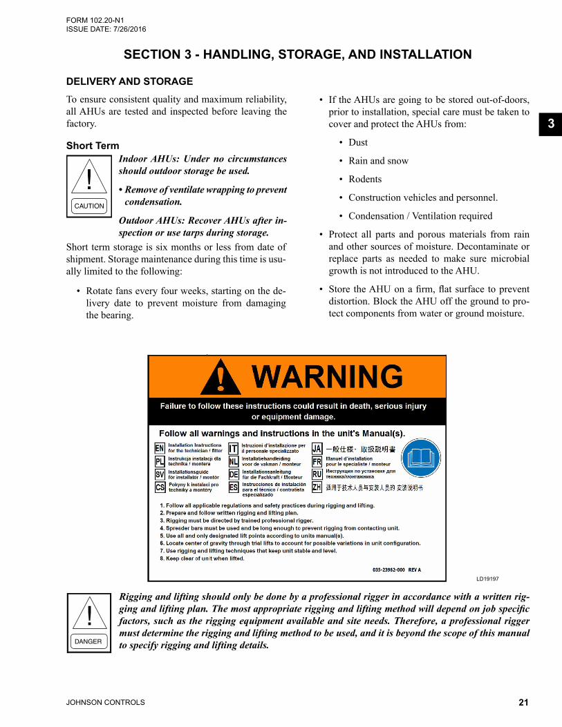
Rigging and lifting should only be done by a professional rigger in accordance with a written rig-ging and lifting plan. The most appropriate rigging and lifting method will depend on job specific factors, such as the rigging equipment available and site needs. Therefore, a professional rigger must determine the rigging and lifting method to be used, and it is beyond the scope of this manual to specify rigging and lifting details.
LD19197

JOHNSON CONTROLS22
FORM 102.20-N1ISSUE DATE: 7/26/2016SECTION 3 - HANDLING, STORAGE, AND INSTALLATION
Long TermLong term storage is more than six months from the date of shipment. If long term storage is anticipated, contact the Johnson Controls sales representative for the proper instructions and requirements.
It is mandatory that a detailed record be maintained during this long term period, such as, but not limited to the following:
• Proper sealing of the cabinet,
• Rotation of the blowers and bearings, and
• Protection of all motors from moisture.
Refer to Long Term Storage Requirement - Field Prep-aration (Form 50.20-NM3) and Long Term Storage Periodic Checklist and Logs (Form 50.20-CL3) for more information.
Failure to fulfill the long term storage requirements will void the warranty.
Receiver’s Responsibility
The receiver is solely responsible for noting the freight bill and filling out the freight claims IMME-DIATELY. In addition, the receiver must:
• Note the visible damage on the signed and dated bill of lading with a request that the carrier inspect the damage within 72 hours of notification.
• Remove the shipping wrapper, and replace it with a tarp or similar protective covering. Any concealed damage reported after 15 days will compromise a claim settlement.
• Request inspections by telephone or in person, but confirm in writing. If assistance is needed with the claim process, contact a Johnson Controls sales representative and refer to the shipping damage form.
INSPECTION, DAMAGE, AND SHORTAGE Check the AHU shipment on arrival to make sure that all major pieces, boxes, and crates are received. Check each AHU on the trailer or rail car when received, be-fore unloading, for any visible signs of damage. Report any damage or signs of possible damage to the trans-portation company immediately for its inspection.
After inspecting the AHU for damage, open all con-tainers and check the contents against the packing list. Report any material shortage to Johnson Controls im-mediately.
JOHNSON CONTROLS WILL NOT BE RESPONSIBLE FOR ANY DAMAGE OR LOSS OF PARTS IN SHIPMENT OR AT JOB SITE. Refer to Shipping Damage Claims (Form 50.15-NM).
Preventive Maintenance Prior to Long Term StorageTake the following precautions prior to extended stor-age:
• Grease the fan and motor bearings per the manu-facturer’sspecifications.
• Protect the motors and sheaves from free moisture or high humidity, which may be accomplished by:
• Spraying components with an anti-rust solu-tion (P/N 026-37707-000).
• Disconnecting the belts. Wrapping the sheaves and motor and sealing them with plastic. Inserting a desiccant to absorb mois-ture that may penetrate the plastic protection.
• Meg the fan motor windings and record for com-parison prior to placing the AHU in service.
• If the fan housing was supplied with a drain con-nection, remove the plug to prevent moisture from accumulating in this part of the fan during storage.
Periodic Fan Check On a monthly basis, perform the following tasks:
• Rotate the fan and motor several times to replen-ish the bearing surfaces with fresh grease.
• Turn the fan impeller 180° from the previous month's position to prevent the belts from taking a set position.
Monthly Log SheetIt is the customer's responsibility to submit a monthly log sheet from the Long Term Storage Periodic Check-list and Logs (Form 50.20-CL3) that shows the condi-tion of the AHU and to note any discrepancies. Send a copy of the log sheet to the Johnson Controls Field Service Office for its records.

JOHNSON CONTROLS 23
SECTION 3 - HANDLING, STORAGE, AND INSTALLATIONFORM 102.20-N1 ISSUE DATE: 7/26/2016
3
Check Solution XT Doors and LatchesRefer to the service manual for adjusting and replacing the doors.
Solution XT doors are shipped with metal shipping spacers glued onto the edges of each door. They are located on three edges of each door. The spacers should be left in place until the AHU is placed in its final loca-tion and multiple skid AHUs are fully assembled. After AHU installation use a channel lock pliers or a screw-driver to remove the spacers. Do not damage the metal door panel. Slight impressions left on the door gasket by the spacers will rebound in approximately a week.
FIGURE 9 - METAL SPACERS ON SOLUTION XT DOORS
LD16574
Indoor AHUsIt is Johnson Controls' intention that a shipping wrap-per be applied to unpainted indoor AHUs for protec-tion from weather, road dirt, etc. during inland transit.Remove the wrapper at the time of delivery to allow for a thorough inspection, both inside and out. Under no circumstances should outdoor storage be used.
Outdoor AHUsGenerally, outdoor AHUs are not fully wrapped. Ex-posed openings will be covered for protection from weather, road dirt, etc. during inland transit. Conduct a thorough inspection, inside and out, at the time of delivery.
Access - All AHU doors have a small clip, which is located on the door frame, and crosses over the edge of the door. This clip is a safety device to prevent injury when the AHU is operating. Remove the clip to inspect the AHU, and replace it when inspection is completed.
Occasionally, an outdoor Solution XT AHU may be en-tirely wrapped in plastic, which should not be removed until the Solution XT AHU is installed, to prevent damage from job site dirt and various weather condi-
tions. If the Solution XT AHU is covered with plastic, cut the wrap in the outline of the door(s), and proceed to access the Solution XT AHU using the information (above). Close the cut with duct tape.
Shipped Loose PartsCheck the packing list, which notes the number and types of parts, for non-mounted shipped loose parts in all segments of the AHU. Report shortages within 10 days after receipt of the order. For more information about the shipped loose parts, refer to Figure 22 on page 30 through Figure 38 on page 33.
LIFTING WEIGHTSAHU section weights are furnished on the job submit-tal form. Due to the variance in weight of each AHU design, it is not possible to list AHU weights in these instructions. Refer to the job submittal form when se-lecting a crane for rigging and figuring out roof weight loads. Weights can also be found on skid ID label for each section. Contact a Johnson Controls sales rep-resentative, if there are questions regarding the AHU weights.
MOVING THE AHUPrior to moving the AHU, make sure that the installa-tion site is suitable for installing the AHU, and is easily capable of supporting the weight of the AHU and all associated services.
RIGGINGSome AHUs are shipped completely assembled. When large AHUs are ordered with multi-zone (MZ) seg-ments in rear discharge location (end of the AHU), the AHUs will ship with the top section (hot deck) separat-ed. In these cases, the complete MZ damper assembly (hot and cold decks) will ship loose.
All lifting points must be used to avoid personal injury, death, or damage to the equipment.
Use all lifting lugs to avoid damage to the AHU. If the AHU is not equipped with lifting lugs, use bottom cor-ner connectors as shown in Figure 12 on page 24, and raceway lifting lugs as shown in Figure 13 on page 25. Do not use top corner connectors. Use come-a-longs as shown in Figure 11 on page 24.

JOHNSON CONTROLS24
FORM 102.20-N1ISSUE DATE: 7/26/2016SECTION 3 - HANDLING, STORAGE, AND INSTALLATION
COME-A-LONGS (POWER PULLS)If the AHU has multiple sections, use come-a-longs (power pulls) as shown in Figure 11 on page 24 to pull the sections or skids together.
LD09613a
FIGURE 11 - TYPICAL COME-A-LONGS
PROPER LIFTING WITH SHACKLES Shackles are fastened to a sling or chain, which is used to lift and lower the sections in a tiered AHU. Refer to the following figures for proper lifting:
• Figure 12 on page 24 for proper lifting with a hook and shackle at the corners.
• Figure 13 on page 25 for proper lifting with a hook and shackle at the lifting lugs.
• Figure 14 on page 25 for lifting with a base rail.
LD13767
FIGURE 12 - PROPER LIFTING WITH SHACKLE WITH CORNER CONNECTOR CORNERS
An experienced and reliable rigger must handle the un-loading and final placement of the AHU, and must be advised of the following:
• AHU contains internal components and should be handled in an upright position.
• Care must be exercised to avoid twisting the equipment structure.
• Prevent unnecessary jarring or rough handling. Proper rigging and handling of the equipment is mandatory during unload-ing and setting it into position to prevent voiding the warranty.
Use the proper spreader bars and hoisting lines when rigging to prevent damage to the AHU casing.
When lifting long AHUs, a special system must be used to insure a minimum 60° angle between the lift-ing lugs and spreader bar/frame.
FIGURE 10 - RECOMMENDED LIFTING WITH MULTIPLE POINTS
USING FORK LIFT IN SPECIAL CIRCUMSTANCESForklifts should not be used to off-load AHUs except in special circumstances. If moving an AHU with a fork lift or similar equipment becomes necessary, make sure the lifting forks are long enough to reach from the fork truck to the opposite side and slightly beyond the AHU. Leave the shipping blocks attached to the bot-tom of the AHU until it is moved to its final location. There is no structural support under the equipment ex-cept what is visible from the perimeter.
SPREADER BARS
60° MINLD13765b

JOHNSON CONTROLS 25
SECTION 3 - HANDLING, STORAGE, AND INSTALLATIONFORM 102.20-N1 ISSUE DATE: 7/26/2016
3
AL13768
FIGURE 13 - PROPER LIFTING WITH SHACKLE AT LIFTING LUG
FIGURE 14 - PROPER LIFTING WITH BASE RAIL
LD13766
PREPARING THE SITEDo not weld or use torches on the ex-terior or interior of the AHU housing. The housing contains polyurethane in-sulation, which, under combustion, will produce harmful, toxic gases resulting in personal injury or death.
Never use silicone caulk/sealant in or on any AHU.
If the AHU has HEPA filters, the filter frames, bulkheads, and segment panels are factory sealed, and must remain sealed to prevent air bypass.
Clearance for Outdoor AHUsLocate the AHU away from building flue stacks or exhaust ventilators to prevent possible introduction of contaminated air through the outside air intakes as shown in Figure 15 on page 26.
To make sure that the AHU fits properly into the se-lected location, use the following instructions.
• AllowsufficientspacearoundtheAHUtoremovethe access panels and various parts.
• Provide a minimum clearance equal to the width of the AHU plus 6 in. on one side to remove the coil or fan assembly. Consider the coil access panel for coil removal.
• Add the dimensions of the pipe chase, air hoods, ducts, control/electrical panels, etc. to meet mini-mum clearances.
• Allow any additional clearances as required by local and National Electrical Codes (NEC).
Mounting the Outdoor AHUInstall AHUs to provide enough elevation for properly designed condensation traps as discussed under Drains and Traps on page 89 in this section.
The area of the roof on which the curb is to be installed must be structurally adequate to support the combined weight of curb, AHU, and system fluids. With these combined weights in place, the resting surface for the AHU MUST be flat and level.
Concrete pads may not be as flat as they should be. Shimming and/or grouting may be necessary. Whether under the AHU base or curb, the AHU base needs to be on a flat plane.

JOHNSON CONTROLS26
FORM 102.20-N1ISSUE DATE: 7/26/2016SECTION 3 - HANDLING, STORAGE, AND INSTALLATION
FIGURE 15 - MINIMUM SERVICE CLEARANCESLD6326-4
MIN. CLEARANCE DIMENSIONS
ABCDEFGH
Fan SectionCoil SectionFace and Bypass Damper SectionFilter Section - Door should open 180°Inlet SectionRain Hood (add unit width or length)Pipe Chase Enclosure (add to unit width)Coil Access Panel on Outdoor Unit(allow clearance = to unit width)
A B C D E F
G
H
24"
24"
24"
UNIT WIDTH + 6 IN.
Assembling the Johnson Controls Provided CurbThe curb, which supports the AHU, will be shipped unassembled, and requires assembly on the job site. Assembly drawings and a hardware package, which includes a nailer and gasket, are shipped with each curb. All other parts such as wood or fiber cant strips, roofing felts and material, caulking, and curb-to-roof fasteners are field supplied.
If there are questions about the number of curb parts or assembling the curb, notify a Johnson Controls Field Service Office immediately.
Use the following instructions to assemble the curb:
1. Unpack the shipping package. Layout the parts according to the exploded views.
2. Layout all channel pieces as shown in Figure 16 on page 27. Make certain that all channel tabs are located on inside of the mating channel. and thatallcurbwalls,accessories,andflanges,whichmay have been distorted in handling, are straight-ened before assembly.
3. Attach the curb walls together to form rectangular perimeter as shown, leaving bolts loose. After the curb is set in place, ensure proper consideration has been given to the air duct openings through the roof.
4. The curb installation drawing shows a gasket that is mounted between the curb and the unit as shown in Figure 16 on page 27. This gasket is shipped with the curb parts. Install the curb gasket before setting the AHU on the curb. The gasket forms an
air seal between the AHU and the curb and serves as a dampener, preventing metal-to-metal contact between the AHU and curb. However, the gasket should not be used as a vibration isolator where the prevention of noise and vibration transmission into the building is critical.
When the AHU is shipped in skids, replace the curb gasket with the caulk provided by contractor.
5. After verifying the curb is square and level, tight-en all bolts, and then anchor appropriately. DO NOT tighten the bolts after anchoring because the curb will be pulled, twisted, and torqued out of square.
6. Mark the exact location for the pipe chase curb. Drill and assemble the pipe chase curb. The job submittal drawing package contains a curb draw-ing that shows the dimensions of the curb and pipe chase.
7. Insulate and roof the curb as required. Refer to Sheet Metal and Air Conditioning Contractors National Association (SMACNA) for counter flashinformation.
Steel FrameWhen a steel frame is used to support the AHU, it must be level, flat without uneven steel frame joints, and support the AHU around the full perimeter. As a gen-eral rule, cross members should be placed every 96 in., in addition to each shipping split.

JOHNSON CONTROLS 27
SECTION 3 - HANDLING, STORAGE, AND INSTALLATIONFORM 102.20-N1 ISSUE DATE: 7/26/2016
3
FIGURE 16 - TYPICAL CURB ASSEMBLY
UNIT WALL
UNIT RACEWAY
PIPE CHASE SECTION VIEWSECTION A-A
2 in
UNIT ROOF CURB
CURB GASKET
CURB REST
1-7/8 in
2 in x 4 in NAILERCURB FOR PIPE CHASE
Note 1
B
LEFT HAND PIPE CHASE
A
C
B
A 2 in
Note 1
DCURB SUPPORTSAS REQUIRED
RIGHT HAND PIPE CHASEA
1-1/2 in1-7/8 in
Screw flange of pipe chase curb to unit roof curb 2 in x 4 in nailer
Screw flange of pipe chasecurb to unit roof curb
DETAIL BPIPE CHASE CURB CONNECTION
TO UNIT CURB
CURB CALCULATION FOR OUTSIDE DIMENSIONSA = Total unit length from YORKworks minus 0.875 in.B = Pipe chase location distance from unit discharge end. Pipe chase Mtg. holes will not be included on pipe chase curb. Mtg. will be field located. C = Pipe chase length muinus 0.875 in.D = Total unit width from YORKworks minus 0.875 in.
WALL PANEL
STANDARD RACEWAY
CURB GASKET
CURB REST
2 in X 4 in NAILER NOMINAL
ROOF CURBNote 1
TYPICAL CURB SECTION FOR UNITS WITHOUT BASE RAIL
DIMENSIONSTYPICAL CURB SECTION FOR
UNITS WITH BASE RAIL
1.25 in
3.5 in
1.50 in
0.438 in TYP.
2.00 in TYP.
1.875 in TYP.
WALL PANEL
STANDARD RACEWAY
STANDARD BASE RAIL
Note 1
Note 2
CURB GASKETCURB REST
2 in X 4 in NAILER NOMINAL
ROOF CURB
NOTES:1. Curbs available in 14, 18, 22, 26, 30 or 34 inches. 2. Outdoor base rails are available in six, eight or 10 inches. Contractor is responsible for providing ductwork to include the height of the base rail. 3. Curb material is glavanized steel, unpainted, and may vary in gauge, and is based on the unit load and the quantity of cross bracing provided.4. If curb space used as plenum, seal all joints and seams with suitable sealer, such as urethane caulk (P/N 013-02966-011). LD09616G

JOHNSON CONTROLS28
FORM 102.20-N1ISSUE DATE: 7/26/2016SECTION 3 - HANDLING, STORAGE, AND INSTALLATION
Clearance and Mounting for Indoor AHUsIt is recommended that the AHU is located in an air -conditioned space. Some suggested installations are shown in Figures 17 through 19 on page 28. Make sure the floor and housekeeping pads are flat and level.
Allow sufficient space around the AHU to remove the access panels and various parts. A minimum clearance equal to the width of the AHU plus 6 in. must be pro-vided on one side of the AHU to remove the coil or fan assembly.
Concrete pads may not be as flat as they should be. Shimming and/or grouting may be necessary. Whether under the AHU base or curb, the AHU base needs to be on a flat plane.
Mounting Indoor AHU
Install the AHUs to provide enough elevation for properly designed condensation traps as discussed in Drains and Traps on page 89.
LD05372
FIGURE 17 - SOLUTION XT NO BASE RAIL - HOUSEKEEPING PAD REQUIRED TO ACCOMODATE TRAP HEIGHT
LD05373
FIGURE 18 - NO HOUSEKEEPING PAD - SOLUTION XT BASE RAIL REQUIRED TO ACCOMODATE TRAP HEIGHT
LD05374
FIGURE 19 - WITH BASE OR BASE RAIL AND HOUSEKEEPING PAD

JOHNSON CONTROLS 29
SECTION 3 - HANDLING, STORAGE, AND INSTALLATIONFORM 102.20-N1 ISSUE DATE: 7/26/2016
3
Installing Ceiling Suspended AHUsIt is recommended that support is structur-ally engineered to prevent flexing, sagging or twisting of the AHUs.
Use the following instructions to prepare the site for ceiling suspended AHUs. Refer to Figure 20 on page 29 for proper support in the direction of airflow, and/or if the AHU is positioned perpendicular to the direction of the air flow.
Structure Positioned in Direction of AirflowThe AHU base must be supported continuously on both sides.
Structure Positioned Perpendicular to AirflowThe AHUs must be supported (at a minimum) at the following locations:
• Both ends
• At each shipping split, if applicable
• Upstream and downstream of each cooling coil segment
• Under heavy components like fans, attenuators, and heating segment.
• As a general rule, cross members should be placed every 96 in., in addition to each shipping split.
DO NOT obstruct the door operation, filter access, piping, electrical or control connections with suspension members.
FIGURE 20 - CEILING SUSPENDED AHU ON STRUCTURAL STEEL
STRUCTURE PARALLEL TO AIRFLOW(units under 60" wide)
STRUCTURE PERPENDICULAR TO AIRFLOW(units over 60" wide)
Plain View Plain ViewAir Flow Air Flow
Fan Section Fan Section
Fan Section Fan Section
Elevation View Elevation View
BDW
CO
OLI
NG
BDW
CO
OLI
NG
MC CCRF RFMB MB

JOHNSON CONTROLS30
FORM 102.20-N1ISSUE DATE: 7/26/2016SECTION 3 - HANDLING, STORAGE, AND INSTALLATION
TOOLS REQUIRED TO INSTALL AHUThe following tools, which are not provided by John-son Controls, are needed to install the AHU. Refer to Figure 21 on page 30 for more information.
• Drill with adjustable torque
• No. 3 Phillips bit
• Allen wrench set
• Nut setter or socket set (1/4 in., 5/16 in., 3/8 in. and 9/16 in.)
• Wire cutters
• Come-a-longs (power pulls)
• Slings
• Pry bar
• Drift pins and awls
• Common hand tools
• Caulking gun
• Shackles
FIGURE 21 - TOOLS NEEDED TO ASSEMBLE SHIPPING SPLITS
LD09613
When the AHU is shipped in skids, re-place the curb gasket with the the caulk provided by the contractor because gas-kets on curbs can pose a problem when sliding skids together for the final con-nection of each shipping split.
SHIPPED LOOSE PARTSThe shipped loose parts, which may be required, are shown in Figure 22 on page 30 through Figure 38 on page 33. Installation instructions for the shipped loose parts are listed on the Installation Instructions and Ship Loose Items Inside label, located on the ac-cess door of the first fan skid in the air stream.
3/8 in. Lock Nut
3/8 x 3/4 in. Button Head Screw
3/8 x 3/4 in. Button Head Screw
FIGURE 22 - SECOND TIER TIE-DOWN FASTENER PACK (P/N 386-03419-000)
LD11029a
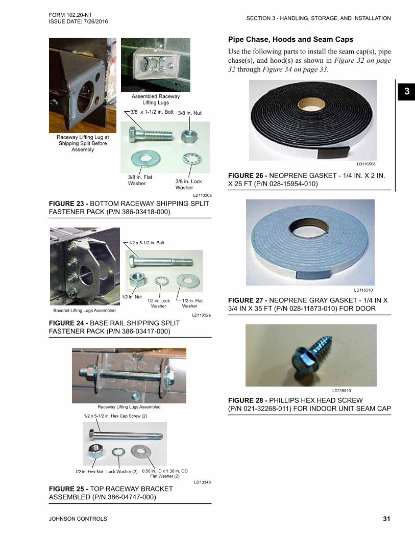
JOHNSON CONTROLS 31
SECTION 3 - HANDLING, STORAGE, AND INSTALLATIONFORM 102.20-N1 ISSUE DATE: 7/26/2016
3
Raceway Lifting Lug at Shipping Split Before
Assembly
Assembled Raceway Lifting Lugs
3/8 x 1-1/2 in. Bolt 3/8 in. Nut
3/8 in. FlatWasher 3/8 in. Lock
Washer
FIGURE 23 - BOTTOM RACEWAY SHIPPING SPLIT FASTENER PACK (P/N 386-03418-000)
LD11030a
Baserail Lifting Lugs Assembled
1/2 in. Flat Washer
1/2 in. Lock Washer
1/2 x 5-1/2 in. Bolt
1/2 in. Nut
FIGURE 24 - BASE RAIL SHIPPING SPLIT FASTENER PACK (P/N 386-03417-000)
LD11032a
1/2 x 5-1/2 in. Hex Cap Screw (2)
0.56 in. ID x 1.38 in. OD Flat Washer (2)
Lock Washer (2)1/2 in. Hex Nut
Raceway Lifting Lugs Assembled
FIGURE 25 - TOP RACEWAY BRACKET ASSEMBLED (P/N 386-04747-000)
LD13349
Pipe Chase, Hoods and Seam CapsUse the following parts to install the seam cap(s), pipe chase(s), and hood(s) as shown in Figure 32 on page 32 through Figure 34 on page 33.
FIGURE 26 - NEOPRENE GASKET - 1/4 IN. X 2 IN. X 25 FT (P/N 028-15954-010)
LD116508
FIGURE 27 - NEOPRENE GRAY GASKET - 1/4 IN X 3/4 IN X 35 FT (P/N 028-11873-010) FOR DOOR
LD116510
FIGURE 28 - PHILLIPS HEX HEAD SCREW (P/N 021-32268-011) FOR INDOOR UNIT SEAM CAP
LD116510

JOHNSON CONTROLS32
FORM 102.20-N1ISSUE DATE: 7/26/2016SECTION 3 - HANDLING, STORAGE, AND INSTALLATION
FIGURE 29 - HEX HEAD SCREW FOR OUTDOOR ROOF SEAM CAP, PIPE CHASE, AND RAIN HOOD - 1/4 IN-14 X 1 IN (P/N 021-30530-052)
LD116513
FIGURE 30 - BUTYL TAPE - 3/16 IN X 3/4 IN X 40 FT (P/N 013E-03327-010)
LD116509
FIGURE 31 - POLYURETHANECAULK (P/N 021-19568-000 - GREY; P/N 013-03317-040 - CHAMPAGNE) FOR PIPE CHASE ONLY
LD116505
Never use silicone caulk/sealant in or on any air handling equipment.
FIGURE 32 - ROOF SEAM CAP (ASSEMBLED)
LD17322
FIGURE 33 - PIPE CHASE, TRIM ANGLE, AND COVER
LD16502
Apply 2 in. Gasketand Caulk
Apply Caulk
Pipe Chase Base Rail Cover
Pipe ChasePipe ChaseTrim Angle
Apply 2 in.Gasket
and Caulk

JOHNSON CONTROLS 33
SECTION 3 - HANDLING, STORAGE, AND INSTALLATIONFORM 102.20-N1 ISSUE DATE: 7/26/2016
3
FIGURE 34 - HOODLD116503
Additional PartsThe following parts may be used later in these instruc-tions.
FIGURE 35 - DAMPER SHAFT EXTENSION KIT (P/N 026-33715-002)
LD116504
LD16514
FIGURE 36 - CORNER CONNECTOR HOLE PLUG (P/N 021-19568-000) (8)
FIGURE 37 - TOUCH-UP SPRAY - 12 OZ. (P/N 013-03322-000)
LD116506
FIGURE 38 - SHIPPING SPLIT CORNER GASKET - 3.5 X 3. 5 (P/N 028-11883-010)
LD116507
FIGURE 39 - SPARE FAN BELTLD116511
FIGURE 40 - CONDUIT (P/N 025-39024-001) AND SJO CORD (P/N 025-35746-001)
JC
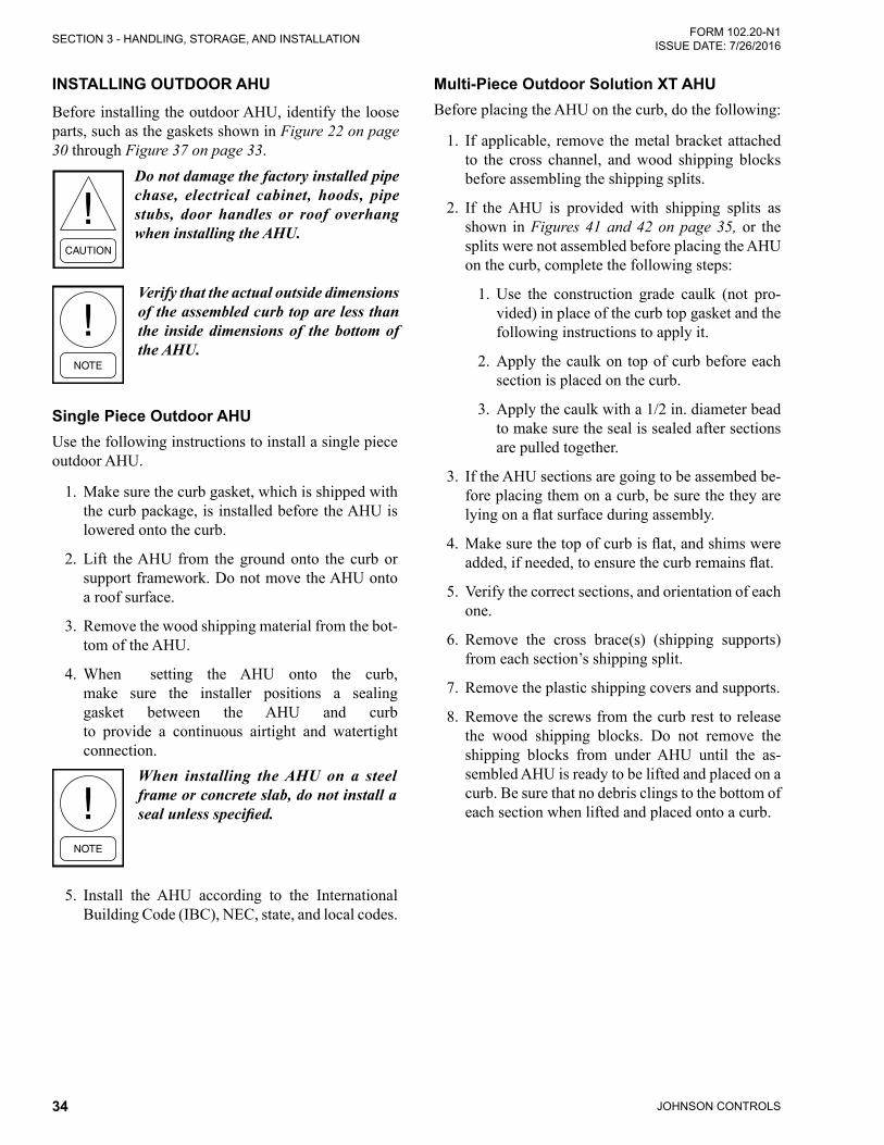
JOHNSON CONTROLS34
FORM 102.20-N1ISSUE DATE: 7/26/2016SECTION 3 - HANDLING, STORAGE, AND INSTALLATION
INSTALLING OUTDOOR AHUBefore installing the outdoor AHU, identify the loose parts, such as the gaskets shown in Figure 22 on page 30 through Figure 37 on page 33.
Do not damage the factory installed pipe chase, electrical cabinet, hoods, pipe stubs, door handles or roof overhang when installing the AHU.
Verify that the actual outside dimensions of the assembled curb top are less than the inside dimensions of the bottom of the AHU.
Single Piece Outdoor AHUUse the following instructions to install a single piece outdoor AHU.
1. Make sure the curb gasket, which is shipped with the curb package, is installed before the AHU is lowered onto the curb.
2. Lift the AHU from the ground onto the curb or support framework. Do not move the AHU onto a roof surface.
3. Remove the wood shipping material from the bot-tom of the AHU.
4. When setting the AHU onto the curb, make sure the installer positions a sealing gasket between the AHU and curb to provide a continuous airtight and watertight connection.
When installing the AHU on a steel frame or concrete slab, do not install a seal unless specified.
5. Install the AHU according to the International Building Code (IBC), NEC, state, and local codes.
Multi-Piece Outdoor Solution XT AHUBefore placing the AHU on the curb, do the following:
1. If applicable, remove the metal bracket attached to the cross channel, and wood shipping blocks before assembling the shipping splits.
2. If the AHU is provided with shipping splits as shown in Figures 41 and 42 on page 35, or the splits were not assembled before placing the AHU on the curb, complete the following steps:
1. Use the construction grade caulk (not pro-vided) in place of the curb top gasket and the following instructions to apply it.
2. Apply the caulk on top of curb before each section is placed on the curb.
3. Apply the caulk with a 1/2 in. diameter bead to make sure the seal is sealed after sections are pulled together.
3. If the AHU sections are going to be assembed be-fore placing them on a curb, be sure the they are lyingonaflatsurfaceduringassembly.
4. Makesurethetopofcurbisflat,andshimswereadded,ifneeded,toensurethecurbremainsflat.
5. Verify the correct sections, and orientation of each one.
6. Remove the cross brace(s) (shipping supports) from each section’s shipping split.
7. Remove the plastic shipping covers and supports.
8. Remove the screws from the curb rest to release the wood shipping blocks. Do not remove the shipping blocks from under AHU until the as-sembled AHU is ready to be lifted and placed on a curb. Be sure that no debris clings to the bottom of each section when lifted and placed onto a curb.

JOHNSON CONTROLS 35
SECTION 3 - HANDLING, STORAGE, AND INSTALLATIONFORM 102.20-N1 ISSUE DATE: 7/26/2016
3
LD09620c
FIGURE 41 - SHIPPING SPLIT EXAMPLES
TOP SPLIT
BOTTOM SPLIT - RACEWAY WITH LUG
BOTTOM SPLIT - RACEWAY WITH LUG AND CURB REST
BOTTOM SPLIT - RACEWAY, BASERAIL WITH LUG
BOTTOM SPLIT - RACEWAY, BASERAIL WITH LUG AND CURB REST
CURB REST
FIGURE 42 - SHIPPING SPLIT EXAMPLES USING STRUCTURAL STEEL BASERAILS
LD14263
WELDED CHANNEL FILLER
BASE CHANNEL
REMOVABLE LIFTING LUGS
BASE CHANNEL
3/4 in ZINC HEX NUT(Use from Lifting Lug)(No Flat or LockWashers Required)
3/4 in GR5 HEX BOLT(Use from Lifting Lug)
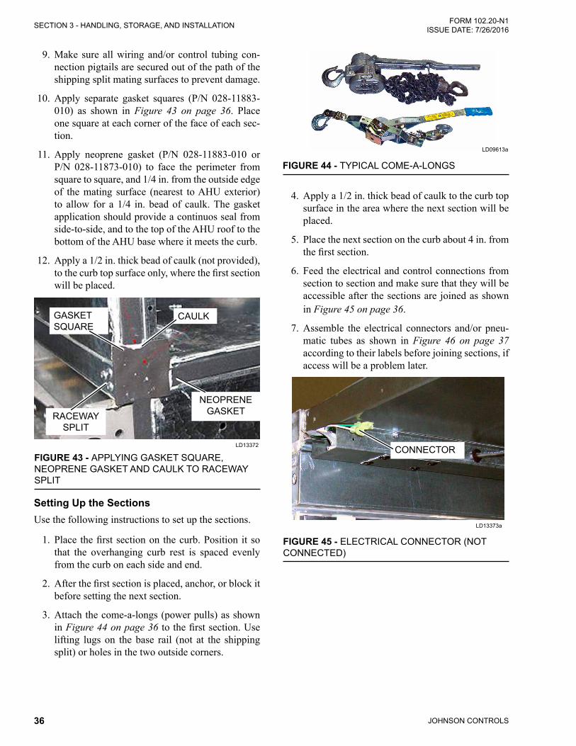
JOHNSON CONTROLS36
FORM 102.20-N1ISSUE DATE: 7/26/2016SECTION 3 - HANDLING, STORAGE, AND INSTALLATION
9. Make sure all wiring and/or control tubing con-nection pigtails are secured out of the path of the shipping split mating surfaces to prevent damage.
10. Apply separate gasket squares (P/N 028-11883-010) as shown in Figure 43 on page 36. Place one square at each corner of the face of each sec-tion.
11. Apply neoprene gasket (P/N 028-11883-010 or P/N 028-11873-010) to face the perimeter from square to square, and 1/4 in. from the outside edge of the mating surface (nearest to AHU exterior) to allow for a 1/4 in. bead of caulk. The gasket application should provide a continuos seal from side-to-side, and to the top of the AHU roof to the bottom of the AHU base where it meets the curb.
12. Apply a 1/2 in. thick bead of caulk (not provided), tothecurbtopsurfaceonly,wherethefirstsectionwill be placed.
FIGURE 43 - APPLYING GASKET SQUARE, NEOPRENE GASKET AND CAULK TO RACEWAY SPLIT
LD13372
NEOPRENEGASKET
GASKET SQUARE
RACEWAY SPLIT
CAULK
Setting Up the Sections Use the following instructions to set up the sections.
1. Place thefirstsectiononthecurb.Position itsothat the overhanging curb rest is spaced evenly from the curb on each side and end.
2. Afterthefirstsectionisplaced,anchor,orblockitbefore setting the next section.
3. Attach the come-a-longs (power pulls) as shown in Figure 44 on page 36 tothefirstsection.Uselifting lugs on the base rail (not at the shipping split) or holes in the two outside corners.
FIGURE 44 - TYPICAL COME-A-LONGS
LD09613a
4. Apply a 1/2 in. thick bead of caulk to the curb top surface in the area where the next section will be placed.
5. Place the next section on the curb about 4 in. from thefirstsection.
6. Feed the electrical and control connections from section to section and make sure that they will be accessible after the sections are joined as shown in Figure 45 on page 36.
7. Assemble the electrical connectors and/or pneu-matic tubes as shown in Figure 46 on page 37 according to their labels before joining sections, if access will be a problem later.
FIGURE 45 - ELECTRICAL CONNECTOR (NOT CONNECTED)
LD13373a
CONNECTOR
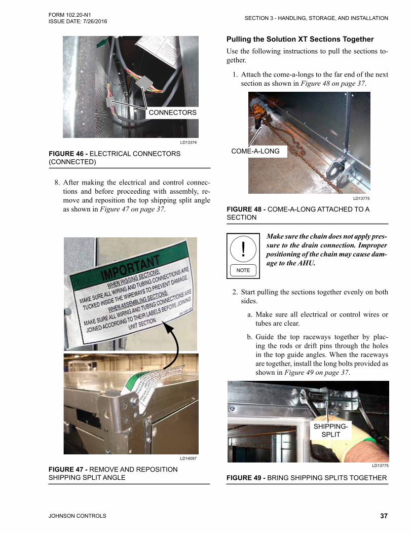
JOHNSON CONTROLS 37
SECTION 3 - HANDLING, STORAGE, AND INSTALLATIONFORM 102.20-N1 ISSUE DATE: 7/26/2016
CONNECTORS
FIGURE 46 - ELECTRICAL CONNECTORS (CONNECTED)
LD13374
8. After making the electrical and control connec-tions and before proceeding with assembly, re-move and reposition the top shipping split angle as shown in Figure 47 on page 37.
Pulling the Solution XT Sections TogetherUse the following instructions to pull the sections to-gether.
1. Attach the come-a-longs to the far end of the next section as shown in Figure 48 on page 37.
FIGURE 48 - COME-A-LONG ATTACHED TO A SECTION
LD13775
COME-A-LONG
Make sure the chain does not apply pres-sure to the drain connection. Improper positioning of the chain may cause dam-age to the AHU.
2. Start pulling the sections together evenly on both sides.
a. Make sure all electrical or control wires or tubes are clear.
b. Guide the top raceways together by plac-ing the rods or drift pins through the holes in the top guide angles. When the raceways are together, install the long bolts provided as shown in Figure 49 on page 37.
FIGURE 49 - BRING SHIPPING SPLITS TOGETHER
LD13775
SHIPPING-SPLIT
FIGURE 47 - REMOVE AND REPOSITION SHIPPING SPLIT ANGLE
LD14097

JOHNSON CONTROLS38
FORM 102.20-N1ISSUE DATE: 7/26/2016SECTION 3 - HANDLING, STORAGE, AND INSTALLATION
c. Guide the bottom raceway/base rails togeth-er, using rods or drift pins through the holes in the lifting lugs on opposite sections simul-taneously.
d. If there is any difficulty aligning the sections, due to racking of one section or the other, use a come-a-long diagonally on the inside of that section at the shipping split or across the tops of the opposite sections.
e. If there is any difficulty aligning the sections due to the top and bottom not pulling to-gether simultaneously, apply shims under the sections as needed to compensate for uneven placement area.
3. Complete pulling the sections together, using the come-a-longs. The bolts hold the sections tight af-ter they are pulled together.
4. Fasten the bottom lifting lugs together with the 1/2 in. x 4 in. bolts in fastener packet (P/N 386-03418-000).
5. Fasten the top raceway bracket with the 1/2 in. x 5-1/2 in. bolts provided in fastener packet (P/N 386-03418-000).
6. Apply a 1/4 in. bead of caulking to exterior of the seam on the roof and both sides as shown in Fig-ure 50 on page 38. Repeat the process for the seamonthefloorinsidetheAHU.
FIGURE 50 - APPLYING CAULK TO SEAMS
LD13776
7. Apply neoprene gasket (P/N 028-15954-010) to the underside of the seam caps, and install them over the joints with hex head screws (P/N 386-04747-000) as shown in Figure 51 on page 38.
Painted seam caps are applied over the joints on the sides and roof of the exterior, and galvanized seamcapsareappliedontheinteriorflooronly.
FIGURE 51 - INSTALLING GASKETS
LD13778
If a roof seam cap has a tab only on one end, the end without the tab goes above the pipe chase location.
8. Repeat this procedure for each additional section.
9. For AHUs or sections without base rails, install the corner connector hole plugs (P/N 021-19568-000) as shown in Figure 52 on page 38 on the bottom raceway corners.
FIGURE 52 - SOLUTION XT CORNER CONNECTOR HOLE PLUG (P/N 021-19568-000)
LD116514

JOHNSON CONTROLS 39
SECTION 3 - HANDLING, STORAGE, AND INSTALLATIONFORM 102.20-N1 ISSUE DATE: 7/26/2016
3
INSTALLING INDOOR SOLUTION XT AHUBefore installing the indoor AHU, identify the shipped loose parts such as gaskets as shown in Figure 22 on page 30 through Figure 39 on page 33.
Do not damage factory installed pipe chase, electrical cabinet, hoods, pipe stubs, door handles or roof overhang when installing AHU.
If the AHU or AHU sections are too large to fit through an opening, contact the local Johnson Controls Field Service Office for assistance. Technical instruc-tions are available for disassembly and reassembly.
Before placing the skids together:
1. If applicable, remove the metal bracket attached to the cross channel and wood shipping blocks before assembling the shipping splits.
2. If AHU sections are going to be assembled before placing them, be sure the sections are on a flatsurface during assembly.
3. Verify the correct sections and orientation of each section.
4. Remove the cross brace(s) (shipping supports) from each section’s shipping split.
5. Remove the plastic shipping covers and supports.
6. Apply neoprene gasket (P/N 028-15954-010) to one side only of each shipping split as shown in Figure 53 on page 39. If there is a door frame at the shipping split, apply neoprene gasket (P/N 028-11873-010) as shown in Figure 54 on page 39. Make sure the entire perimeter is covered with the gasket material, including the foamed corners as shown in Figure 54 on page 39. Any void, depression, or protrusion will allow air or water leakage. Make any splices on a straight run.
LD13779
FIGURE 53 - USE GASKET (P/N 028-11883-010) AT SHIPPING SPLIT
GASKET
DOOR FRAME
FLANGE
LD13380a
FIGURE 54 - USE GASKET (P/N 028-11873-010) TO DOOR FRAME AT SHIPPING SPLIT
CONNECTORS OUT OF THE WAY
PANEL FLANGE
GASKET
Installing a Solution XT AHU with Expanded Cabinet
If the AHU has an expanded cabinet with end channel shipping splits, use the following steps to install it:
1. Remove the shipping brackets in corners.
2. Clean the metal surface where gasket is to be ap-plied with mineral denatured alcohol or rubbing alcohol.

JOHNSON CONTROLS40
FORM 102.20-N1ISSUE DATE: 7/26/2016SECTION 3 - HANDLING, STORAGE, AND INSTALLATION
FASTENER PACK (P/N 386-03419-000)
SHIPPING BRACKETS
HEAT WHEEL SEGMENT
FIGURE 55 - ASSEMBLY OF END CHANNEL SHIPPING SPLIT WITH A SOLUTION XT EXPANDED CABINET
LD14262a
INTERMEDIATE RACEWAY
3. Apply the neoprene gasket to all raceway mating surfaces of one mating section. On large AHUs, install two gaskets side by side on intermediate raceway surfaces.
4. Make sure that the sections are not racked and will line up properly.
5. Attach the sections as follows:
a. Make sure assembly surface is clean and lev-el to allow the sections to slide freely. If the surface is irregular, use as many metal shims under sections as necessary to align mating surfaces.
b. Pull the sections together, using a come-a-long.
c. Attach the sides of the sections. Beginning at the bottom of the sections, secure the end channel assembly brackets together using fastener pack (P/N 386-03419-000) at each bracket. Continue securing the end channel assembly brackets together, working from bottom to top, pulling the sections tight.
d. After the sides are secured, secure the brack-ets on top of the AHU with the same brackets mentioned in Step 3.

JOHNSON CONTROLS 41
SECTION 3 - HANDLING, STORAGE, AND INSTALLATIONFORM 102.20-N1 ISSUE DATE: 7/26/2016
3
Setting Up and Pulling Solution XT Sections TogetherUse the following instructions to set up and pull the sections together.
1. Placethefirstsectioninitsfinalpositionandan-chor or block it before placing the next section.
2. Attach the come-a-longs to the far end of the next section as shown in Figure 56 on page 41.
FIGURE 56 - COME-A-LONG ATTACHED TO A SECTION
LD13775
COME-A-LONG
Make sure the chain does not apply pres-sure to the drain connection. Improper positioning of the chain may cause dam-age to the AHU.
3. If the AHU is equipped with an optional expand-ed cabinet with a structural steel base, remove the lifting lugs within the shipping split shown in Fig-ure 57 on page 41. Keep the bolts and nuts.
FIGURE 57 - REMOVE LIFTING LUGS IN EXPANDED CABINET
LD14265
LIFTING LUG
BASE CHANNEL
WELDED-CHANNEL
FILLER
4. Place the next section on the curb about 8 in. from thefirstsection.
5. Feed the electrical and control connections from section to section and make sure that they will be accessible after the sections are joined as shown in Figure 58 on page 41.
FIGURE 58 - ELECTRICAL CONNECTOR (NOT CONNECTED)
LD13373a
CONNECTOR
6. Assemble the electrical connectors and/or pneu-matic tubes according to their labels before join-ing the sections as shown in Figure 59 on page 41, if access will be a problem later.
FIGURE 59 - ELECTRICAL CONNECTORS (CONNECTED)
LD13374
CONNECTORS
7. After making the electrical and control connec-tions, and before proceeding with assembly, re-move and reposition the top shipping split angle as shown in Figure 60 on page 42.

JOHNSON CONTROLS42
FORM 102.20-N1ISSUE DATE: 7/26/2016SECTION 3 - HANDLING, STORAGE, AND INSTALLATION
FIGURE 60 - REMOVE AND REPOSITION SHIPPING SPLIT ANGLE
LD14097
8. Attachthecome-a-longstothefarendofthefirstsection.
9. Start pulling the sections together. Pull evenly on both sides.
a. Make sure all electrical or control wires or tubes are clear.
b. Guide the top raceways together by placing rods or drift pins through the holes in the top guide angles. When the raceways are togeth-er, install the long bolts provided as shown in Figure 61 on page 42.
FIGURE 61 - BRING SHIPPING SPLITS TOGETHER
LD13775
SHIPPING-SPLIT
c. Guide the bottom raceway/base rails togeth-er, using rods or drift pins through the holes in the lifting lugs on opposite sections simul-taneously.
d. If there is any difficulty aligning the sections, due to racking of one section or the other, use a come-a-long diagonally on the inside of that section at the shipping split or across the tops of the opposite sections.
e. If there is any difficulty aligning the sections due to the top and bottom not pulling to-gether simultaneously, apply shims under the sections as needed to compensate for uneven placement area.
10. Complete pulling the sections together, using the come-a-longs. The bolts hold the sections tight af-ter they are pulled together.
11. Fasten the bottom lifting lugs together with the 1/2 in. x 5-1/2 in. bolts in fastener packet (P/N 386-03418-000) as shown in Figure 62 on page 43.
12. Fasten the top raceway bracket with the 1/2 in. x 5-1/2 in. bolts in fastener packet (P/N 386-03418-000).
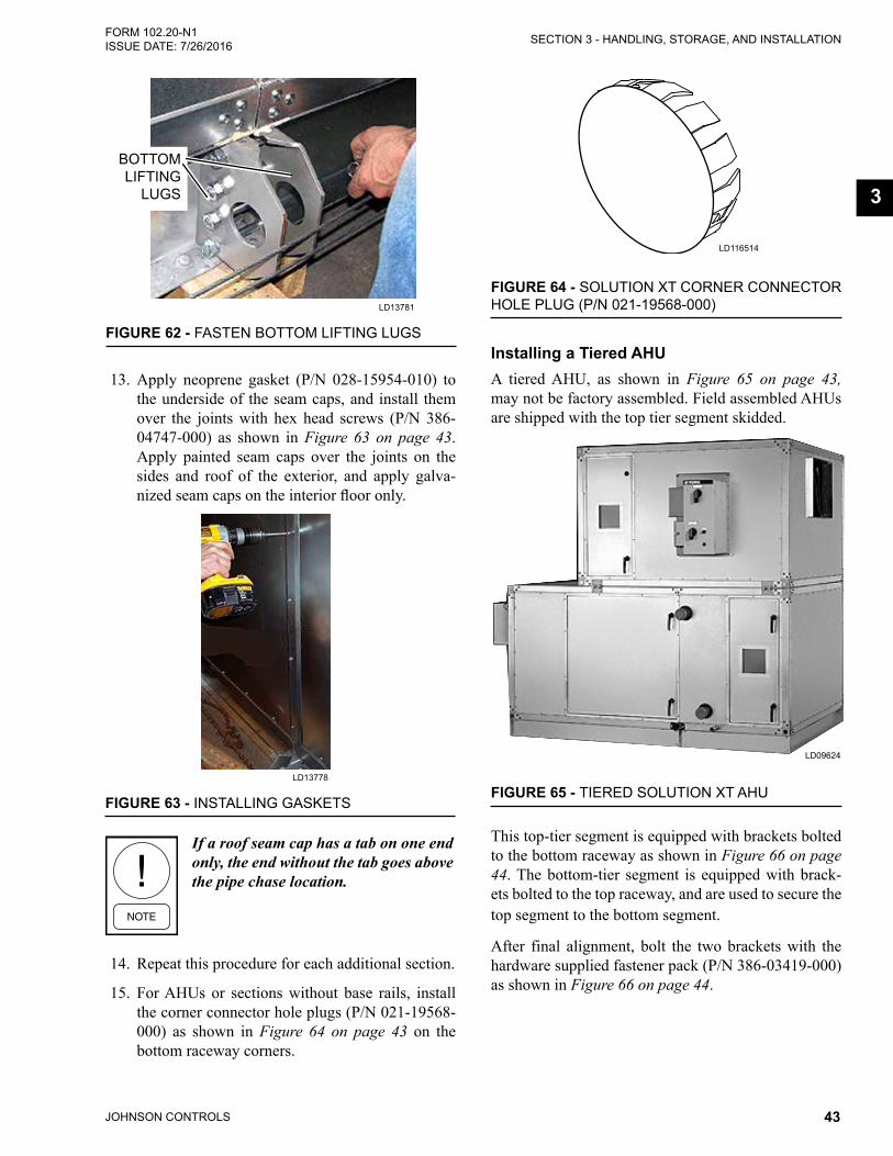
JOHNSON CONTROLS 43
SECTION 3 - HANDLING, STORAGE, AND INSTALLATIONFORM 102.20-N1 ISSUE DATE: 7/26/2016
3
LD13781
FIGURE 62 - FASTEN BOTTOM LIFTING LUGS
BOTTOM LIFTING
LUGS
13. Apply neoprene gasket (P/N 028-15954-010) to the underside of the seam caps, and install them over the joints with hex head screws (P/N 386-04747-000) as shown in Figure 63 on page 43. Apply painted seam caps over the joints on the sides and roof of the exterior, and apply galva-nizedseamcapsontheinteriorflooronly.
FIGURE 63 - INSTALLING GASKETS
LD13778
If a roof seam cap has a tab on one end only, the end without the tab goes above the pipe chase location.
14. Repeat this procedure for each additional section.
15. For AHUs or sections without base rails, install the corner connector hole plugs (P/N 021-19568-000) as shown in Figure 64 on page 43 on the bottom raceway corners.
FIGURE 64 - SOLUTION XT CORNER CONNECTOR HOLE PLUG (P/N 021-19568-000)
LD116514
Installing a Tiered AHUA tiered AHU, as shown in Figure 65 on page 43, may not be factory assembled. Field assembled AHUs are shipped with the top tier segment skidded.
FIGURE 65 - TIERED SOLUTION XT AHU
LD09624
This top-tier segment is equipped with brackets bolted to the bottom raceway as shown in Figure 66 on page 44. The bottom-tier segment is equipped with brack-ets bolted to the top raceway, and are used to secure the top segment to the bottom segment.
After final alignment, bolt the two brackets with the hardware supplied fastener pack (P/N 386-03419-000) as shown in Figure 66 on page 44.

JOHNSON CONTROLS44
FORM 102.20-N1ISSUE DATE: 7/26/2016SECTION 3 - HANDLING, STORAGE, AND INSTALLATION
3/8 in. Lock Nut
3/8 x 3/4 in. Button Head Screw
3/8 x 3/4 in. Button Head Screw
FIGURE 66 - SECOND TIER TIE-DOWN FASTENER PACK (P/N 386-03419-000)
LD11029a
1. Verify the correct sections and orientation of the top and bottom tiers.
2. Remove cross brace(s) (shipping supports) from the top tier.
3. Remove the plastic shipping covers and supports.
4. Make sure all wiring and/or control tubing con-nection pigtails are secured out of the path of the mating surfaces to prevent damage during rigging.
5. Make sure the neoprene gasket (P/N 028-15954-010) is properly installed on the bottom tier. If the toptierisshorterinthedirectionofairflowthanthe bottom tier, apply the gasket material on the top panel of the bottom tier from raceway to race-way, but not on top of the raceways as shown in Figure 67 on page 44.
FIGURE 67 - APPLY GASKETS TO TOP PANEL ON BOTTOM TIER
LD09690
TOP TIER
TOP LEFTRACEWAY TOP PANEL
BOTTOM TIER
TOP RIGHTRACEWAY
6. Apply the second layer of gasket (P/N 028-15954-010) over top of the gasket applied in Step 5, but include the raceways. Steps 5 and 6 are necessary because the top panel of the bottom tier is slightly recessed below the height of its raceways.
7. If the top tier has shipping splits, refer to Install-ing Indoor Solution XT AHU on page 39 for the correct assembly procedure.
Make sure all of the electrical or control wires or tubes in both tiers are clear.
8. Install four shackles, one in each bottom corner connector or raceway lifting lug. Refer to the properliftingprocedureforthespecificshacklesunder Proper Lifting with Shackles on page 24.
9. Fasten the sling/chain to the shackles and the oth-er end of the sling/chain to the spreader bar (as needed).
10. Lift the top tier assembly with a crane or overhead lift.
11. Feed the electrical and control connections from the top tier to bottom tier, and make sure that they will be accessible after the sections are joined. If any connections will not be accessible, assemble the electrical connectors and/or pneumatic tubes according to the labels before joining the top and bottom tiers.
12. Lower the top tier onto bottom tier so that mount-ing brackets mate. Guide the brackets together, using rods or drift pins through the bolt holes as shown in Figure 68 on page 44.
FIGURE 68 - GUIDE BRACKETS TOGETHER
LD09626

JOHNSON CONTROLS 45
SECTION 3 - HANDLING, STORAGE, AND INSTALLATIONFORM 102.20-N1 ISSUE DATE: 7/26/2016
Carefully place each section of the top tier without dis-turbing the gaskets on the bottom tier.
13. Secure the top tier to bottom tier with 3/8 in. x 0.75 in. allen head bolts.
14. Install the corner connector hole plugs (P/N 021-19568-000) as shown in Figure 64 on page 43 onto the bottom raceway corners.
Lights for Tiered Solution XT AHU (If Appli-cable)
If the AHU is equipped with lights, the following parts are shipped loose on a tiered unit, as shown in Figure 69 on page 45.
• Conduit (P/N 025-39024-001)
• SJO Cord (P/N 025-35746-01)
JUMPER
FIGURE 69 - SOLUTION XT LIGHTS TIER TRANSITION DRAWING
LD16602
CONDUIT
Assembling the Solution XT End Channel Shipping Split
The assembly is the same regardless which sections are connected together.
Use the following instructions to prepare the sections before they are attached.
1. Remove the shipping brackets in the corners.
2. Clean the metal surface where gasket is to be ap-plied with mineral denatured alcohol or rubbing alcohol.
3. Apply the neoprene gasket to all raceway mating surfaces of each section. On large AHUs, install two gaskets side by side on the intermediate race-way surfaces.
4. Make sure that the sections are not racked, and will line up properly.
5. Attach the sections as follows:
a. Make sure assembly surface is clean and level to allow the sections to slide freely. If the surface is irregular, use metal shims un-der sections as necessary to align mating sur-faces.
b. Pull the sections together using a come-a-long, drawing the base together.
c. Attach the sides of the sections. Beginning at the bottom of the sections, secure the end channel assembly brackets together using fastener pack (P/N 386-03419-000) at each bracket. Continue securing the end channel assembly brackets together, working from bottom to top, pulling the sections tight.
d. After the sides are secured, secure the brack-ets on top of the AHU with the same hard-ware removed in Step 4.

JOHNSON CONTROLS46
FORM 102.20-N1ISSUE DATE: 7/26/2016SECTION 3 - HANDLING, STORAGE, AND INSTALLATION
FIGURE 70 - ASSEMBLING THE END CHANNEL SHIPPING SPLIT WITH ENERGY RECOVERY WHEEL
FASTENER PACK (P/N 386-03419-000)
SHIPPING BRACKETS
HEAT WHEEL SEGMENT
NEOPRENE GASKET
END SPLIT MOUNTINGBRACKET
BASE RAIL SUPPORT PLATE
INTERMEDIATE RACEWAY
LD14262

JOHNSON CONTROLS 47
SECTION 3 - HANDLING, STORAGE, AND INSTALLATIONFORM 102.20-N1 ISSUE DATE: 7/26/2016
3
Installing Hood with Moisture Eliminators1. Identify the correct hood and its respective loca-
tion by looking at the label as shown in SECTION 2 - PRODUCT DESCRIPTION in this manual.
2. Correct orientation is with the tracks or bird screens to thebottom.Themountingflangesarepre-drilled.
3. Each hood is fittedwith a factory installed birdscreen unless the moisture eliminator option is se-lected.
4. ApplytheButyltapetothepre-drilledhoodflang-es and back wall angle that contact the AHU pan-els.
5. Use the hex head screws with the EPDM washer provided in the fastener pack.
6. Completely cover each damper opening in the AHU panels by its respective hood. The bottom of the hood should extend approximately 6 in. below the AHU panel opening.
7. Center each hood over the width of the opening. All hoods, especially those containing barometric dampers, MUST be installed square.
8. Seal each hood gutter to the AHU panel with the polyurethane caulk (provided).
9. When multiple hoods are installed in a stacked space, the hoods should be approximately 1 1/2 in. apart so that the bottom hood will extend 6 in. below the bottom of the opening.
10. If equipped, install the optional moisture elimina-tors as shown in Figure 71 on page 47 using the following instructions.
a. Remove the clip(s) from the leading edge of the hood.
b. Insert the proper size moisture eliminator or filter into the tracks.
c. Reinstall the clip(s) on the leading edge of the hood.
Outdoor Air Temperature and/or Humidity SensorsWhen outside air hoods are shipped loose with AHUs that include factory packaged controls, these sensors will be dismounted and pulled back into the AHU. The contractor should find them secured with tape inside, and put them through their respective penetration to the exterior, and mount them to the bracket provided.
MOISTURE ELIMINATOR
CLIP
BUTYL TAPE
CAULK
FIGURE 71 - INSTALLING HOOD WITH OPTIONAL MOISTURE ELIMINATORS
LD13783
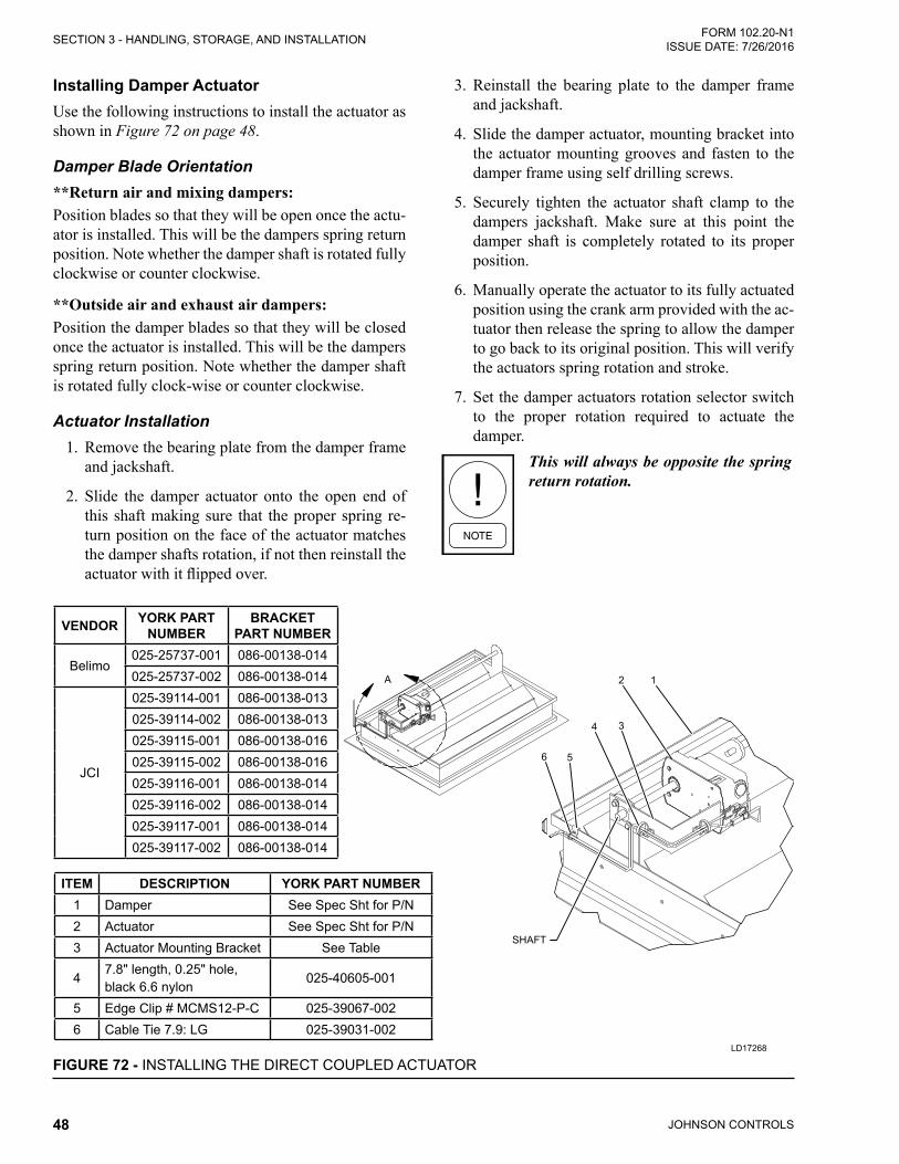
JOHNSON CONTROLS48
FORM 102.20-N1ISSUE DATE: 7/26/2016SECTION 3 - HANDLING, STORAGE, AND INSTALLATION
Installing Damper ActuatorUse the following instructions to install the actuator as shown in Figure 72 on page 48.
Damper Blade Orientation**Return air and mixing dampers:Position blades so that they will be open once the actu-ator is installed. This will be the dampers spring return position. Note whether the damper shaft is rotated fully clockwise or counter clockwise.
**Outside air and exhaust air dampers:Position the damper blades so that they will be closed once the actuator is installed. This will be the dampers spring return position. Note whether the damper shaft is rotated fully clock-wise or counter clockwise.
Actuator Installation1. Remove the bearing plate from the damper frame
and jackshaft.
2. Slide the damper actuator onto the open end of this shaft making sure that the proper spring re-turn position on the face of the actuator matches the damper shafts rotation, if not then reinstall the actuatorwithitflippedover.
3. Reinstall the bearing plate to the damper frame and jackshaft.
4. Slide the damper actuator, mounting bracket into the actuator mounting grooves and fasten to the damper frame using self drilling screws.
5. Securely tighten the actuator shaft clamp to the dampers jackshaft. Make sure at this point the damper shaft is completely rotated to its proper position.
6. Manually operate the actuator to its fully actuated position using the crank arm provided with the ac-tuator then release the spring to allow the damper to go back to its original position. This will verify the actuators spring rotation and stroke.
7. Set the damper actuators rotation selector switch to the proper rotation required to actuate the damper.
This will always be opposite the spring return rotation.
LD17268
FIGURE 72 - INSTALLING THE DIRECT COUPLED ACTUATOR
ITEM DESCRIPTION YORK PART NUMBER1 Damper See Spec Sht for P/N2 Actuator See Spec Sht for P/N3 Actuator Mounting Bracket See Table
47.8" length, 0.25" hole, black 6.6 nylon
025-40605-001
5 Edge Clip # MCMS12-P-C 025-39067-0026 Cable Tie 7.9: LG 025-39031-002
VENDOR YORK PART NUMBER
BRACKET PART NUMBER
Belimo025-25737-001 086-00138-014025-25737-002 086-00138-014
JCI
025-39114-001 086-00138-013025-39114-002 086-00138-013025-39115-001 086-00138-016025-39115-002 086-00138-016025-39116-001 086-00138-014025-39116-002 086-00138-014025-39117-001 086-00138-014025-39117-002 086-00138-014

JOHNSON CONTROLS 49
SECTION 3 - HANDLING, STORAGE, AND INSTALLATIONFORM 102.20-N1 ISSUE DATE: 7/26/2016
3
Installing Multi-Zone (MZ) DampersIf the MZ segment has a shipping split, a rear discharge at the end of the AHU, and a MZ damper, the damper will be shipped loose.
1. Identify the gaskets and hardware needed for in-stallation.
2. After the AHU top tier is assembled to the bottom tier and sealed, install the MZ damper assembly, which includes the hot (top) deck and cold (bot-tom) deck damper banks that are already connect-ed at each blade as shown in Figure 73 on page 49.
Distortion will result in unreliable blade operation.
3. Remove the 16-gauge shipping plate, which is located between the hot and cold decks from air entering side only.
4. Applytheneoprenegaskettothemountingflang-es of the damper assembly.
5. Center the damper assembly over the discharge openings of the hot and cold decks.
6. Attach the damper assembly to the AHU's outer perimetermountingflange,usingthescrews pro-vided.
7. Remove the 16-gauge shipping plate from the air leaving side.
8. Install the screws through themounting flangesbetween the hot and cold decks.
LD12029a
FIGURE 73 - INSTALLING MZ DAMPER
ACTUATOR(P/N 025-39032-002)
SCREW1/4 in. - 14 X .75 in.
(P/N 025-19515-000)
MOUNTING BKT(P/N 086-03474-516)
MOUNTING FLANGES
HOT DECK DAMPER
COLD DECK DAMPER
FACTORY INSTALLED COU-PLER
AIR FLOW
SHAFT EXTENSION KIT(P/N 026-33715-002)
MOUNTING BKT(P/N 086-03474-516)
ACTUATOR(P/N 025-39032-002)
SCREW1/4 in. - 14 X .75 in.
(P/N 025-19515-000)
MOUNTING FLANGES
COLD DECK DAMPER
HOT DECK DAMPER
SHIPPING PLATE AIR ENTERING
SHIPPING PLATE AIR LEAVING
EXTENSION PIN

JOHNSON CONTROLS50
FORM 102.20-N1ISSUE DATE: 7/26/2016SECTION 3 - HANDLING, STORAGE, AND INSTALLATION
Installing Field Supplied MZ Damper Actuators When the actuators are field supplied for MZ dampers, use the following information to select the correct size actuator.
• Required torque is 7 in-lb/sq. ft of damper area up to 2500 feet per minute (FPM).
• Damper blades are 6 in. wide and vary in height.
• Calculate the torque by the number and size of blades in each zone. There are hot deck blades di-rectly connected to cold deck blades.
• Determine the number of blades per zone by the system cubic ft per minute (CFM), and static pres-sure requirements for each zone by the engineer’s construction documents.
• Cut the blade linkage (flat rods) connecting allblades of each deck at the appropriate places to di-vide the decks into correct size zones. These rods are mounted externally on the assembly. Make suretocutoutasectionoftheflatconnectingrod,which will prevent interference when the zones modulate in opposite directions.
• One damper shaft extension kit (P/N 026-33715-002), as shown in Figure 74 on page 50 is pro-vided for each zone per the factory order form.
FIGURE 74 - DAMPER SHAFT EXTENSION KIT (P/N 026-33715-002)
LD116504
• The contractor should supply the actuators and mounting brackets. The part numbers are avail-able upon request.
• On the rear mount (discharge through end of the AHU), always mount the actuators on the top of the upper deck.
• Do not allow the duct insulation to restrict the damper blades or external linkage.
• Direct coupled actuators are recommended.
• Make duct connections at the zone dividers with-out restricting the damper blade(s).
BACK DRAFT DAMPERS FOR DUAL FANS AND FAN ARRAYS The counterbalance is locked into place for shipping as shown in Figure 75 on page 50. Before startup, the counterbalance will have to be released. To do this, loosen the set screws and slide the counterbalance off the end of the shaft. Flip the counterbalance and slide it back on the shaft. Rotate the counterbalance above the damper as shown in Figure 76 on page 50, and then tighten the set screws. The counterbalance should be free to rotate.
FIGURE 75 - COUNTERBALANCE LOCKED INTO PLACE FOR SHIPPING
LD17103
FIGURE 76 - COUNTERBALANCE UNLOCKED FOR START-UP
LD17198

JOHNSON CONTROLS 51
SECTION 3 - HANDLING, STORAGE, AND INSTALLATIONFORM 102.20-N1 ISSUE DATE: 7/26/2016
3
FILLING INERTIA FAN BASE Inertia fan bases are pre-engineered according to the fan and motor size. Use the following instructions to fill an inertia fan base with concrete.
• Calculate the amount of concrete by measuring the overall length and width of the fan base as-sembly cavities that have the corrugated metal bottoms. The standard depth of a cavity is 4 in.
• Fill each cavity to the top with wet concrete. Do not get concrete mix on the bolts and adjusting parts of the adjustable motor base, sheaves, belts, oronthefloorundertheedgesoftheisolatedfanbase.
STEAM HUMIDIFIERIf purchased, steam humidifiers are provided with fac-tory mounted dispersion equipment inside the AHU. The steam injection or generating equipment, meter-ing devices, and sundries are shipped loose with the AHU. Humidifier manufacturer’s installation, opera-tion and maintenance information is packaged with the humidifier. The installing contractor(s) is responsible for supplying all required steam supply and condensate piping, and wiring.
UVC EMITTER LAMPSIf purchased, the contractor is responsible for install-ing the UV lamps, and connecting a 120 volt power supply as shown in Figure 77 on page 51. The John-son Controls factory provides the following pre-wired parts.
• Internal wiring with a magnetic door safety switch
• A lockable disconnect switch with a Press to Test pilot light
• A latching circuit that has to be manually re-ener-gized on the AHU's exterior after a door has been opened and closed.
Use clean cotton rags, clean jersey or latex gloves to handle the lamps. DO NOT touch UV lamps with bare hands or leather gloves because the oil will damage the lamps.
FIGURE 77 - V-MAX GRID LAMPS
V_Max
Two Types of LampsThree different types of UV lamps are used in AHUs: V-Mod and V-Max Grid.
V-Mod Lamps - Install the two-pronged lamps into the slotted fixtures as shown in Figure 78 on page 51, then rotate the lamp 90°.
FIGURE 78 - INSTALLING V-MOD LAMP
LD16551
V-Max Grid Lamps - Fit the four-pronged lamp into the clamp mounted on the UV segment where a pigtail is installed. Insert the prongs into the pigtail plug.
FIGURE 79 - INSTALLING V-MAX GRID LAMPS
LD16552

JOHNSON CONTROLS52
FORM 102.20-N1ISSUE DATE: 7/26/2016SECTION 3 - HANDLING, STORAGE, AND INSTALLATION
THIS PAGE INTENTIONALLY LEFT BLANK.

JOHNSON CONTROLS 53
SECTION 3 - HANDLING, STORAGE, AND INSTALLATIONFORM 102.20-N1 ISSUE DATE: 7/26/2016
3
FIGURE 80 - UV CONTROL PANEL WIRING (8 AMPS)
LD16xxx
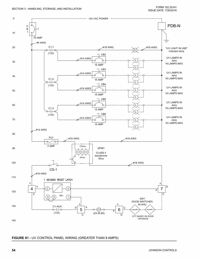
JOHNSON CONTROLS54
FORM 102.20-N1ISSUE DATE: 7/26/2016SECTION 3 - HANDLING, STORAGE, AND INSTALLATION
FIGURE 81 - UV CONTROL PANEL WIRING (GREATER THAN 8 AMPS)

JOHNSON CONTROLS 55
SECTION 3 - HANDLING, STORAGE, AND INSTALLATIONFORM 102.20-N1 ISSUE DATE: 7/26/2016
3
Sequence of Operation:Discounnecting Means of UV lighting will be accomplished by "CB1" internal to the panel. "CB1" is cable of being locked out by panel latching mechanism. "SW1" is a proximity switch with a magnet, which will close a set of normally open contracts. The magnet will engage the "SW1" contact when-ever it is within 1/2" of the switch. "TDR1" is one second (1sec) time delay relay having normally open contacts. When power is initiated, its contacts will close for one second then re-open. To reset, power, power must be removed from "TDR1""C1" is a dpdt 24 vac control relay, used to seal-in its coil and provide interlocking means to the UV lights. If all doors are closed, all the "SW1"s will allow "C1" to energize, as long as power is available.By selecting "CS-1" to the "on" position, the 24vac control power circuit will be energized. As long as all doors with door switches (SW1) are closed and upon detection of power to the 1 second time-delay realy (TDR-1), the "TDR-1" normally open contracts will close for one second, energizing the contactor "C1" will remain energized. Should any one door having "SW1" mounted, were to open, "C1" will de-energize, deacti-vating the UV lamps. Closing all doors will not turn on UV lights. "CS-1" will be required, to be cycled "Off" then back "On" to allow the lights to come back on. If the power is removed from the UV control panell and re-energized (such as when power fluctuates off then back on), the UV lights will reactivate automatically. The "IL" "UV Light In USe" indcator lamp will alow the user to know if the lights have been energized.
LD16609
FIGURE 81 - UV CONTROL PANEL WIRING ( GREATER THAN 8 AMPS) (CONT'D)

JOHNSON CONTROLS56
FORM 102.20-N1ISSUE DATE: 7/26/2016SECTION 3 - HANDLING, STORAGE, AND INSTALLATION
AIR MEASURING DEVICE CONNECTIONS
Air Measuring at the Fan Inlets• COMETER is a probe attached to the fan bearing
support on Comefri Forward Curve fans from size 7 x 7 up to 18 x 18. The probe is located on the outboard side of the housed fan assembly. The probe is piped to the negative (-) port of a factory mounted transducer on the fan wall. The positive (+) port is left open to the fan section. Wiring is not provided to the transducer unless factory packaged controls were selected.
• PIEZORING(PIEZOMETER) is afittingor se-riesoffittingsintheinletcone(s)ofhousedfanslarger than 18 x 18 and all sizes of Plenum fans that are combined into a single connection piped to the negative (-) port of a factory mounted trans-ducer on the fan wall. The positive (+) port is left open to the fan section. Wiring is not provided to the transducer unless factory packaged controls were selected.
The fan manufacturer does not recom-mend placement of the flow measuring probes inside the fan inlet cone in the path of airflow. These devices create disturbances and unpredictable perfor-mance losses.
FIGURE 82 - HIGH AND LOW CONNECTIONS FOR AN IN FAN AIR MONITORING SYSTEM
LD17231
FIGURE 83 - HIGH AND LOW CONNECTIONS AND ASSOCIATED TUBING FOR FAN MOUNTED AIR MONITORING SYSTEM
LD17232
FIGURE 84 - PORT LOCATIONS FOR FAN MOUNTED AIR MONITORING SYSTEM
LD17233
High PortLow Port
Air Measuring at Unit Outside Air Inlets• AMS-60 used on Indoor Solution air handlers
usually measure outside air. This can be provided with one or two pairs of positive (+ or High) and negative (- or Low) pressure tube connections. Connect (+) & (-) respectively to the (+) & (-) ports of the transducer(s). Wiring & transducer are not provided unless factory packaged controls were selected.
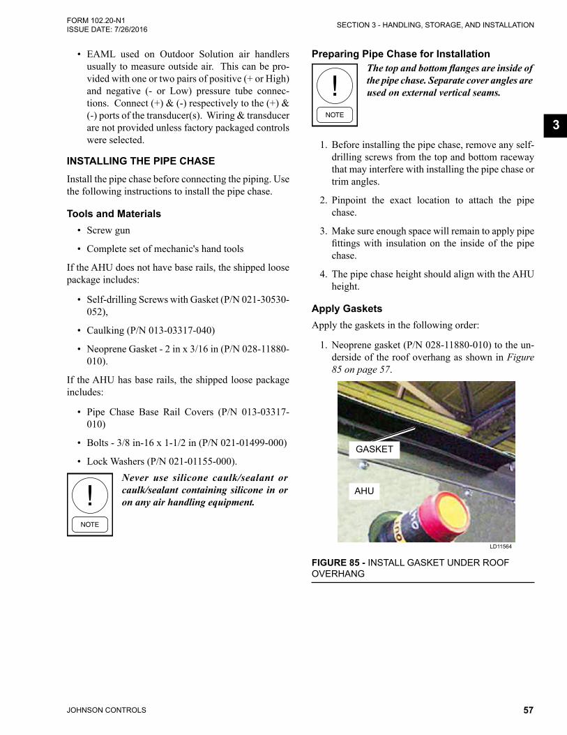
JOHNSON CONTROLS 57
SECTION 3 - HANDLING, STORAGE, AND INSTALLATIONFORM 102.20-N1 ISSUE DATE: 7/26/2016
3
• EAML used on Outdoor Solution air handlers usually to measure outside air. This can be pro-vided with one or two pairs of positive (+ or High) and negative (- or Low) pressure tube connec-tions. Connect (+) & (-) respectively to the (+) & (-) ports of the transducer(s). Wiring & transducer are not provided unless factory packaged controls were selected.
INSTALLING THE PIPE CHASEInstall the pipe chase before connecting the piping. Use the following instructions to install the pipe chase.
Tools and Materials• Screw gun
• Complete set of mechanic's hand tools
If the AHU does not have base rails, the shipped loose package includes:
• Self-drilling Screws with Gasket (P/N 021-30530-052),
• Caulking (P/N 013-03317-040)
• Neoprene Gasket - 2 in x 3/16 in (P/N 028-11880-010).
If the AHU has base rails, the shipped loose package includes:
• Pipe Chase Base Rail Covers (P/N 013-03317-010)
• Bolts - 3/8 in-16 x 1-1/2 in (P/N 021-01499-000)
• Lock Washers (P/N 021-01155-000).Never use silicone caulk/sealant or caulk/sealant containing silicone in or on any air handling equipment.
Preparing Pipe Chase for InstallationThe top and bottom flanges are inside of the pipe chase. Separate cover angles are used on external vertical seams.
1. Before installing the pipe chase, remove any self-drilling screws from the top and bottom raceway that may interfere with installing the pipe chase or trim angles.
2. Pinpoint the exact location to attach the pipe chase.
3. Make sure enough space will remain to apply pipe fittingswith insulationon the insideof thepipechase.
4. The pipe chase height should align with the AHU height.
Apply GasketsApply the gaskets in the following order:
1. Neoprene gasket (P/N 028-11880-010) to the un-derside of the roof overhang as shown in Figure 85 on page 57.
FIGURE 85 - INSTALL GASKET UNDER ROOF OVERHANG
LD11564
GASKET
AHU

JOHNSON CONTROLS58
FORM 102.20-N1ISSUE DATE: 7/26/2016SECTION 3 - HANDLING, STORAGE, AND INSTALLATION
2. Gasket to the top of the curb (provided by curb vendor),
3. Vertical neoprene gasket (P/N 028-11880-010) to the pipe chase,
4. Horizontal neoprene gasket with the outside edg-es of the housing. Horizontal gaskets must com-pletely overlap vertical gaskets in all four corners as shown in Figure 86 on page 58.
VERTICAL GASKET
FIGURE 86 - APPLY GASKET TO PIPE CHASE
LD12560a
HORIZONTAL GASKET
PIPE CHASE
Attach Pipe Chase1. Set the pipe chase on the pipe chase curb 3 in.
away from the AHU.
2. Tilt the top of the pipe chase toward the AHU. Work it under the roof overhang. Be careful not to damage the neoprene gaskets. Lift the pipe chase slightly to clear the curb gasket, and swing the bottom into the AHU.
3. If equipped, attach the pipe chase base rail to the AHU base rail. Place the 3/8 in. bolts and lock washers (provided) through the pipe chase brack-ets into the threaded holes in the AHU as shown in Figure 87 on page 58.
FIGURE 87 - INSTALL PIPE CHASE BASE RAIL TO AHU BASE RAIL
LD12034c
BOLTLOCK
WASHER
RIVET NUT
BASE RAIL COVER PIPE CHASE
BASERAIL
UNIT BASERAIL
4. Make sure the pipe chase is square and the door(s) close and open without rubbing or binding.
5. Secure the pipe chase to the top and bottom race-ways (heavy gage metal) of the AHU through the pre-punched holes of the inside top and bottom flangeswiththeself-drillingscrewsasshowninFigure 88 on page 58.
FIGURE 88 - INSTALL FLANGES LD12561a
Do not overtighten or strip the self-drilling screws. The screws in the top and bottom flanges should be used in heavier gauge metal than screws in cover angles.
6. Make sure the door closes and latches properly. If not, loosen the screws, realign the pipe chase and retighten the screws. Occasionally, the curb under the pipe chase may be uneven, depending on the installation.
INSTALL SCREWS
PIPE CHASE

JOHNSON CONTROLS 59
SECTION 3 - HANDLING, STORAGE, AND INSTALLATIONFORM 102.20-N1 ISSUE DATE: 7/26/2016
3
Seal Pipe Chase to Solution XT AHU1. If the AHU is equipped with base rails, apply
caulking to all exterior joints between the pipe chase, and the base rails as shown in Figure 89 on page 59.
CAULK AT DOTTED
LINE
FIGURE 89 - APPLY CAULK TO SOLUTION XT BASE RAIL
LD12035a
AHUPIPE
CHASE
2. Add a small bead of Manus Bond, Loctite, or Bostik champagne caulking to the exterior verti-cal seam between the AHU and the pipe chase to insure a complete seal as shown in Figure 90 on page 59. Pay special attention to the top and bottom corners, raceway and base rail engage-ments, and under the roof overhang.
3. Starting at the center and working toward each end, run the self-drilling screws down through the AHU overhang into the top of the pipe chase through the gasket. Use caution not to strip the 20-gauge housing with the screws. Line up the screws with a double row of screws on top of the AHU raceway, plus one spaced evenly between each screw as shown in Figure 91 on page 59. (No caulking required.)
FIGURE 91 - INSTALL PIPE CHASE TO SOLUTION XT ROOF
LD16554
PIPE CHASE
SELF-DRILLING SCREWS
Install Cover Angles1. Install the cover angles before the caulking ap-
plied to the exterior joints and base rails dries.
2. Apply the neoprene gasket (P/N 028-11880-010) to the contact side of the cover angle.
3. Remove the top and bottom self-drilling screws from the pipe chase and set aside for later use.
4. Place the cover angles in the vertical corners of the pipe chase and AHU wall.
5. Install the cover angles into the vertical corners of the pipe chase and AHU wall as shown in Figure 92 on page 59. The notch on the cover angle must be on the AHU side.
FIGURE 92 - INSTALL COVER ANGLE LD12564
PIPE CHASE
AHU
COVER ANGLE
FIGURE 90 - APPLY CAULK BETWEEN PIPE CHASE AND SOLUTION XT AHU
LD12565
PIPE CHASE
AHU
APPLY CAULK

JOHNSON CONTROLS60
FORM 102.20-N1ISSUE DATE: 7/26/2016SECTION 3 - HANDLING, STORAGE, AND INSTALLATION
Install Base Rail Covers (If Applicable)1. Caulk the perimeter of the base rail cover as
shown in Figure 95 on page 60.
FIGURE 95 - APPLY SOLUTION XT BASE RAIL COVER
LD12032b
UNIT BASERAIL
APPLY CAULK
PIPE CHASE BASERAIL
COVER
PIPE CHASE BASERAIL
CaulkApplication
CoverInstallation
2. Apply the cover to the base rail seam between both sides of the pipe chase and AHU. No screws are required.
3. Flash,seal,andinsulateallpipechasefloorpen-etrations to prevent condensation entering build-ing.
6. Attach the cover angle to the AHU and pipe chase panels as shown in Figure 93 on page 60. In-stall the self drilling screws (removed earlier) to the top and bottom holes on the cover angle.
FIGURE 93 - POSITION COVER ANGLE PROPERLYLD12563
PIPE CHASE
AHU
NOTCH
7. Starting at the top and alternating between the AHU and pipe chase, continue installing self drill-ing screws until reaching the bottom as shown in Figure 94 on page 60. Use caution not to strip the 20-gauge housing with the screws.
PIPE CHASE
FIGURE 94 - PROPERLY INSTALL SCREWS
LD12562
AHU
TOP SCREWS
BOTTOM SCREWS

JOHNSON CONTROLS 61
SECTION 3 - HANDLING, STORAGE, AND INSTALLATIONFORM 102.20-N1 ISSUE DATE: 7/26/2016
3
INSTALLING EXTERNAL VENT PIPING FOR OUTDOOR AHUS
For outdoor AHUs with an overall height less than 102 in (8 1/2 ft), the external vent piping parts will be factory installed.
For outdoor AHUs with an overall height more than 102 in. (8 1/2 ft), the external vent piping parts will be shipped loose for field mounting. Figure 96 on page 61 shows some generic instructions to install the piping parts. An installation manual specific to the fuel venting system will be provided.
Condensate Drain ArrangementThe indirect fired gas heat exchanger has the poten-tial to create highly acidic condensation, particularly during extended operation at low capacity or low fir-ing rate conditions. To insure proper drainage, use the following instructions as shown in Figure 97 on page 62.
When constructing the condensate trap for the heat exchanger drainage system, make sure the trap is tall enough to handle the total static pressure (TSP) of the indoor blower at low fire times. For example, if a TSP is 6 in. at low fire, construct a trap that is 12 in. tall as shown in Table 2 on page 62.
5.50
12EXT.
7.75
FIGURE 96 - GAS FURNACE FUEL VENTING SYSTEM
LD13326
FLUE CAPVSI PIPE
SPLIT CLAMPPIPE CHASE
SPLIT PLATE
RACEWAY
SIDE PANEL
GAS FURNACE WITH CASING
HAT CHANNEL
ID FAN
TRANSITION PIECE
0.43 IN CLEARANCE
IVSI PIPE
SLIP JOINT
CURB PIECE
CONTAINMENT BAND SET, GASKET AND INSULATION FIBER
STORM COLLAR
STEP 1
STEP 2STEP 3
STEP 4

JOHNSON CONTROLS62
FORM 102.20-N1ISSUE DATE: 7/26/2016SECTION 3 - HANDLING, STORAGE, AND INSTALLATION
TABLE 2 - TSP AND DRAIN TRAPMODEL DRAIN NPT A B C
DF-15/25 1/2 in. 4 in. 2 in. 2 in.DF-30/50 1/2 in. 8 in. 4 in. 4 in.DF-60/75 1 in. 8 in. 4 in. 4 in.
DF-85/200 1 in. 12 in. 6 in. 6 in.DF-225/400 1 in. 16 in. 8 in. 8 in.
Failure to follow these instructions may cause excessive condensation buildup, resulting in water damage to the facility and/or a cracked heat exchanger.
1. Observe local codes for gravity condensate drain-age requirements.
2. Install the AHU at an elevation that enables prop-er condensate drainage and trapping dimensions as shown in Figure 97 on page 62. Minimum trap dimensions MUST be accommodated.
3. The condensate drain line size must be the full line size of the heat exchanger drain connection.
4. Drainlines,fittings,andsupportsshouldconformto local codes, and be suitable for the application.
5. Condensate drain and trap discharge should be pitched away from the equipment at a slope of 1/4 in. per linear foot or as local code dictates.
6. For outdoor or unconditioned space installations, local climate may dictate the need to heat trace and/or insulate the exposed drain lines and trap. Frozen drain lines and/or trap will cause build up of condensate inside the heat exchanger, resulting in leakage and damage to the AHU, and possibly to the building.
7. Provide unions in drain lines to allow removing the trap for periodic cleaning of drain lines and the trap. When the burner is operated at low capacity for extended periods, more condensate is generat-ed, and with it deposits of solids in the condensate drainage system.
8. Provide the ability to prime the trap. During initial and seasonal start-up, trap inspection and priming is required. Condensate in the trap will evaporate during long periods of non-use.
1
1
2
43
1
2
3
4 Foot
FIGURE 97 - GAS FURNACE CONDENSATE DRAIN TRAP
LD12912
BURNER ASSY
FLOW
PITCH
FIELD INSTALLED CONDENSATE DRAIN PIPING - BY OTHERS
CLEAN OUT
WATER SEAL PRIME/ FILL
PITCH 1/4" / FOOT
IDMOTOR

JOHNSON CONTROLS 63
SECTION 3 - HANDLING, STORAGE, AND INSTALLATIONFORM 102.20-N1 ISSUE DATE: 7/26/2016
3
FIELD PENETRATIONS FOR PIPING AND ELECTRICAL CONNECTIONS
Make sure all penetrations and grom-mets are positively sealed on the cabinet exterior.
For small sizes such as 1/2" iron pipe, 1/2" conduit or 5/8" O.D. copper and smaller; it is acceptable to use caulk instead of a grommet.
Electrical conduits must be sealed in-ternally to prevent airflow and moisture condensation.
Tools Required• Drill motor.
• Pilot starter bit.
• Hole saws-approximately 2-1/2", 3-1/4" & 4-1/2" diameter for holes.
• Power cords as required.
Material Required• Neoprene grommet, 2-1/2", 3-1/4", 4-1/2" or
5-1/2" as required (see Fig. 5-98).
• Cold galvanized paint.
• Paint, touchup spray, champagne, P/N 013-03322-000 (for outdoor unit exterior only).
• Caulk, P/N 013-02966-011 gray for indoor units or 013-03317-040 for outdoor units with cham-pagne paint.
• Exacto knife.
• Clean up supplies.
ProcedureSee Figure 98 on page 64
1. Make sure any components; bulkheads or other obstructions are disconnected from panel inside and out.
2. Layout location and dimensions of hole opening to be cut. Do this on both sides of double wall panels.
3. Carefully cut correct hole size for the application in panel, insuring cuts on both sides line up and a smooth clean cut is made.
4. Paint raw edges of sheet metal with cold galva-nized paint.
5. Select appropriate grommet for new panel hole and cut out appropriate hole diameter for penetra-tion with an Exacto knife.
6. After paint dries, Install grommet into panel hole opening.
7. Apply sealant all around new hole opening behind lip of grommet, on both sides of panel.
8. Run pipe or conduit through grommet and make appropriate connections.
9. Allmodifiedpanelsmustprovideintegrityequaltooriginalequipmentspecifications.
10. Reconnect any components, bulkheads or other fixturesthatweredisconnectedfrompanelinstep# 1.
11. Thoroughly clean up inside and outside air unit.
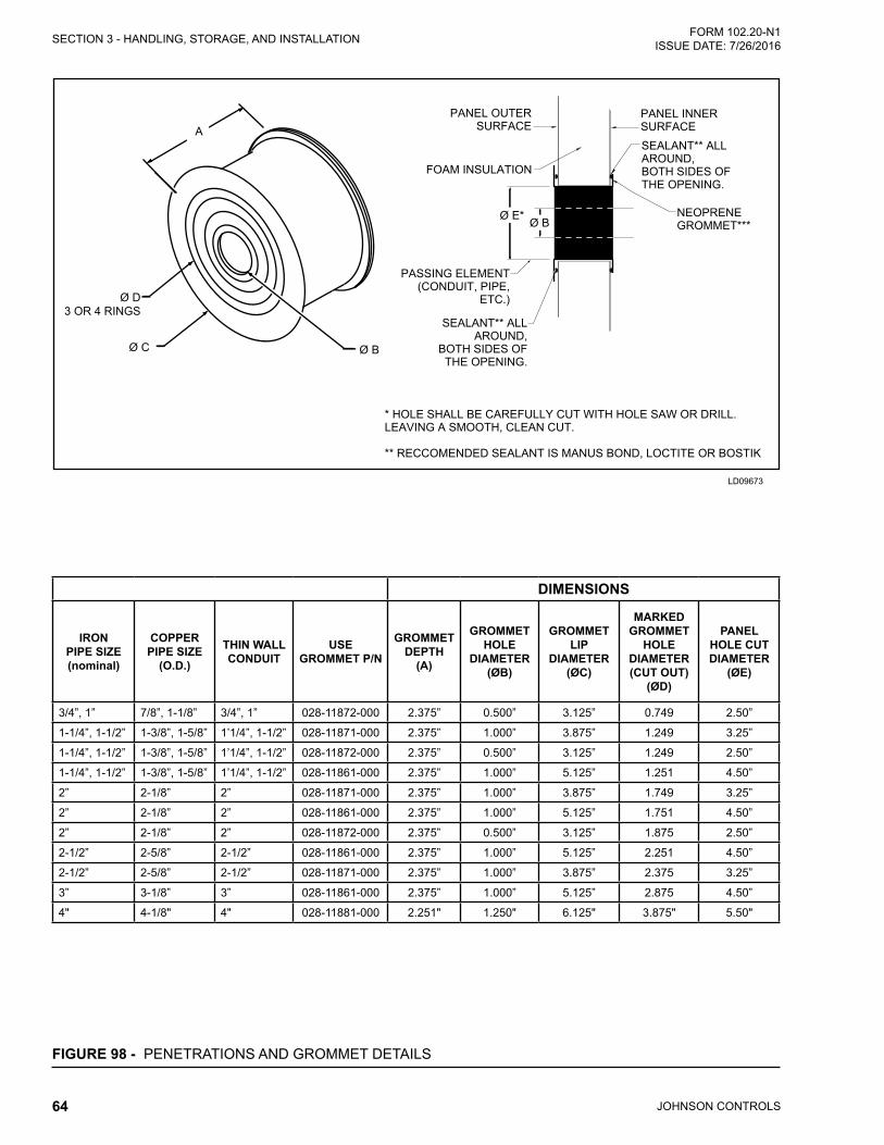
JOHNSON CONTROLS64
FORM 102.20-N1ISSUE DATE: 7/26/2016SECTION 3 - HANDLING, STORAGE, AND INSTALLATION
FIGURE 98 - PENETRATIONS AND GROMMET DETAILS
A
Ø C Ø B
Ø D3 OR 4 RINGS
NEOPRENEGROMMET***
SEALANT** ALL AROUND,BOTH SIDES OF THE OPENING.
PANEL INNER SURFACE
PANEL OUTER SURFACE
PASSING ELEMENT(CONDUIT, PIPE,
ETC.)
FOAM INSULATION
* HOLE SHALL BE CAREFULLY CUT WITH HOLE SAW OR DRILL. LEAVING A SMOOTH, CLEAN CUT.
** RECCOMENDED SEALANT IS MANUS BOND, LOCTITE OR BOSTIK
SEALANT** ALL AROUND,
BOTH SIDES OF THE OPENING.
Ø BØ E*
DIMENSIONS
IRON PIPE SIZE (nominal)
COPPER PIPE SIZE
(O.D.)
THIN WALL CONDUIT
USE GROMMET P/N
GROMMET DEPTH
(A)
GROMMET HOLE
DIAMETER(ØB)
GROMMET LIP
DIAMETER(ØC)
MARKED GROMMET
HOLEDIAMETER (CUT OUT)
(ØD)
PANEL HOLE CUT DIAMETER
(ØE)
3/4”, 1” 7/8”, 1-1/8” 3/4”, 1” 028-11872-000 2.375” 0.500” 3.125” 0.749 2.50”
1-1/4”, 1-1/2” 1-3/8”, 1-5/8” 1’1/4”, 1-1/2” 028-11871-000 2.375” 1.000” 3.875” 1.249 3.25”
1-1/4”, 1-1/2” 1-3/8”, 1-5/8” 1’1/4”, 1-1/2” 028-11872-000 2.375” 0.500” 3.125” 1.249 2.50”
1-1/4”, 1-1/2” 1-3/8”, 1-5/8” 1’1/4”, 1-1/2” 028-11861-000 2.375” 1.000” 5.125” 1.251 4.50”
2” 2-1/8” 2” 028-11871-000 2.375” 1.000” 3.875” 1.749 3.25”
2” 2-1/8” 2” 028-11861-000 2.375” 1.000” 5.125” 1.751 4.50”
2” 2-1/8” 2” 028-11872-000 2.375” 0.500” 3.125” 1.875 2.50”
2-1/2” 2-5/8” 2-1/2” 028-11861-000 2.375” 1.000” 5.125” 2.251 4.50”
2-1/2” 2-5/8” 2-1/2” 028-11871-000 2.375” 1.000” 3.875” 2.375 3.25”
3” 3-1/8” 3” 028-11861-000 2.375” 1.000” 5.125” 2.875 4.50”
4" 4-1/8" 4" 028-11881-000 2.251" 1.250" 6.125" 3.875" 5.50"
LD09673

JOHNSON CONTROLS 65
SECTION 3 - HANDLING, STORAGE, AND INSTALLATIONFORM 102.20-N1 ISSUE DATE: 7/26/2016
3
GENERAL ELECTRICAL INFORMATIONAll field wiring must conform to the International Building Codes (IBC), National Electrical Code (NEC) and local codes.
The AHU is ETL listed. Some compo-nents are UL labeled. Any changes in the field may affect its validity.
The current characteristics of phase, cycle and voltage are stamped on the nameplate of each component. Use the following instructions to set up the electrical con-nections.
• Install electrical conduit connections, which are made to exposed boxes, to the bottom of the box. Outdoor installation must be made watertight. The installing contractor is responsible for electri-cal conduit penetrations through the building roof.
• Seal the penetrations through the panels.
• Externally and internally seal the electrical con-duits that penetrate the AHU exterior (walls, pipe chaseorfloors)sothattheunconditionedairwillnot be drawn into the AHU through and around the conduit. Unconditioned air will result in con-densation that will fail components prematurely.
• Check all accessible electrical connections, which contain several strands of wire, for tightness prior to start-up. The wires are tightened at the time of assembly, but check, and retighten them, if neces-sary. The dangers of a poor connection are over-heating and component failure.
DO NOT PENETRATE any main or aux-iliary drain pan or roof of outdoor AHU.
DO NOT PENETRATE wireways in any manner. The sheet metal channels, which run along the top panel, contain electrical wires and connections. Electrical shock and/or damage to the AHU may result.
Electrical drawings are provided in the information packet on the inside of the AHU access door. Major optional components will have specific electrical and installation information inside the control panels or will be attached. Refer to SECTION 5 - WIRING DI-AGRAMS in the Air Handling Units - Operation and Maintenance Manual (Form 102.20-OM2) for more information on the electrical drawings.
POWER CONNECTIONS
Single Point PowerWhen ordered, the single point power connection pro-vides the installer with a main disconnect switch as shown in Figure 99 on page 65. The line side of this switch (top) is where the installer is to connect his main power wires. The devices included in the single point power option are :
• Supply, Return, and Exhaust Fans
• Energy Recovery Wheel
• Gas and Electric Heat
• Ultra-violet Lights
FIGURE 99 - SINGLE POINT POWER CONNECTION
LD16607
Special quoted devices not included in this option may be purchased with the AHU, and will require separate, additional power wiring by the installer. When this op-tion is NOT purchased, the installer is responsible for wiring to each electrical component.

JOHNSON CONTROLS66
FORM 102.20-N1ISSUE DATE: 7/26/2016SECTION 3 - HANDLING, STORAGE, AND INSTALLATION
Motors for Supply, Return, and Exhaust FansA motor connection diagram may be found on the in-side of the motor terminal box or on a tag attached to the motor. Be sure to make a flexible conduit connec-tion at the motor to permit fan belt adjustment and movement of the spring isolated fan assembly. Refer to the motor data nameplate for all motor specifications as shown in Figure 100 on page 66.
FIGURE 100 - TYPICAL MOTOR DATA/NAME PLATE
Baldor
FIGURE 101 - ANOTHER TYPICAL MOTOR DATA/NAME PLATE
Teco
To access the motor electrical box when the motor is installed in the configuration as shown in Figure 102 on page 66, use the following instructions.'
1. Remove the motor bolts that secure the motor to the motor base.
In some applications, only three bolts need to be removed. The fourth bolt, located on the opposite side of the electri-cal box, does not have to be removed but will need to be loosened. After it is loose, rotate the motor to access the electrical box to make the connections.
2. Remove the belts.
3. Rotate the motor or move it back far enough to access the electrical box.
4. Connect the motor wiring per the motor wiring diagram.
5. Replace the motor electrical box cover.
6. Rotate or move the motor back into place and se-cure it to the base with the bolts.
7. Reinstall the belts to the proper alignment and tension according to the drive kit label found on the fan assembly.
FIGURE 102 - ACCESS ELECTRICAL BOX
LD16561
FANMOTOR
ELECTRICAL BOX
WIRING THE ENERGY RECOVERY WHEELIt is the installer's responsibility to wire the energy re-covery wheel, if single point power was not purchased. Using the attached plug and/or pigtail is optional. John-son Controls does not provide pre-wired mating cables.
For wheels that are 52 in diameter and smaller, the mo-tor comes with a cord. Wheels that are 54 in. in diam-eter and greater, the motor does not come with a cord. Single phase motors have a 3-pin standard AMP con-nector on the cord. Three phase and VFD models have a 4-pin standard AMP connector on the cord.

JOHNSON CONTROLS 67
SECTION 3 - HANDLING, STORAGE, AND INSTALLATIONFORM 102.20-N1 ISSUE DATE: 7/26/2016
3
FIGURE 103 - TYPICAL POWER WIRING OF ENERGY RECOVERY WHEEL
LD12591
WIRING THE GAS HEAT DEVICEIt is the installer's responsibility to wire this device, if the single point power connection was not purchased.
Panel locations and sizes vary based upon the AHU's size and burner configurations. Burner voltage is se-lected to match the primary AHU voltage. Modulation control voltage 2-10 VDC is standard.
Electrical penetrations can come through the floor or side wall panels. Drill and properly seal any penetra-tions to keep out moisture. Refer to the service manual for more information.
Make power connections per the wiring diagrams pro-vided on the inside of the burner control panel. Refer to the Air Handling Units - Operation and Maintenance Manual (Form 102.20-OM2) for more information.
FIGURE 105 - MAIN POWER AND CONTROL PANEL WITH COVER OPEN
LD11597
FIGURE 104 - GAS BURNER COMPONENT LOCATIONSLD11596b
MAIN POWER AND CONTROLTERMINATION PANEL
INSIDE GAS BURNER PIPE
CHASE
BURNER CONTROL PANEL
FLUE CONNECTOR
ID FAN
ID FAN MOTOR
DRAFT DAMPERADJUSTABLEQUADRANT

JOHNSON CONTROLS68
FORM 102.20-N1ISSUE DATE: 7/26/2016SECTION 3 - HANDLING, STORAGE, AND INSTALLATION
WIRING THE ELECTRIC HEAT DEVICEIt's the installer's responsibility to wire this device, if the single point power was not purchased.
Power OptionsThe available power options are listed below:
• 460V-3PH
• 208/230V-3PH
• 380V-3PH
• 575V-3PH
Disconnect Switch OptionsThe available disconnect switch options are fused and non-fused.
Knockouts are provided on the top and bottom of the enclosure for field penetrations. Drill the foam panel to utilize these knockout locations. Seal the penetra-tions to prevent airflow or leakage. Refer to the service manual for more information.
Use the following instructions to connect the discon-nect switch:
1. Hook up the power, as shown in Figure 106 on page 68. Terminals (shown) are for a 2-stage 24 VAC control interface, and may require a 120VAC control interface, based upon the options selected. Refer to the wiring diagram on the inside cover of the electric heat control panel for more informa-tion.
FIGURE 106 - TYPICAL ELECTRICAL HEAT CONTROL PANEL INTERIOR WIRING AND COMPONENTS
LD115934a
HIGH TEMPERATURE CUTOUT
AIRFLOW PROVING SWITCH
STAGING CONTACTORS
CONTROL VOLTAGE TRANSFORMER
MAIN DISCONNECT
SWITCH
KNOCKOUTS
FIGURE 107 - TYPICAL FIELD AND POWER CONNECTIONS
LD11595
FIELD CONTROL WIRING AND INTERFACE TERMINALS
MAIN DISCONNECT SWITCH

JOHNSON CONTROLS 69
SECTION 3 - HANDLING, STORAGE, AND INSTALLATIONFORM 102.20-N1 ISSUE DATE: 7/26/2016
3
2. Seal the electrical conduits that penetrate the AHU's exterior (walls, pipe chase orfloors) ex-ternally and internally so that the unconditioned air will not be drawn into the AHU through and around the conduit. The unconditioned air will result in condensation that will fail components prematurely.
3. Check all accessible electrical connections for tightness prior to the actual startup. Many connec-tions contain several strands of wire, and while they were tightened at the time of assembly, they should be checked and retightened if needed. The dangers from a poor connection are overheating and component failure.
DO NOT PENETRATE any main or aux-iliary drain pan.
Control OptionsThe available control options are:
• Staging - Has no controller, but contactors are energized by providing control power to each contactor from the external BMS source.
• Step Controller - A mechanical/electrical device that receives a 0 to 10 VDC or 4 to 20 mA signal, and step-on heat stages.
• Vernier Silicone Controlled Rectifier (SCR)
• Completely electronically controlled by varying signal and varying output between stages.
• Increases power to a stage by modulation un-til another stage is needed.
• Energizes another stage and modulates pow-er until another stage is needed. 0 to 10 VDC or 4 to 20 mA.
• Less expensive than a full SCR. This system utilizes a step controller and one SCR that modulates and resets for each stage.
• Full SCR - Completely electronically controlled by varying signal and varying output of a control-ler like a VFD for electric heat with 0 to 10 VDC or 4 to 20 mA. The controller modulates a sepa-rate SCR for each stage.
Installing Electrical Heat OptionRotating parts and electrical shock haz-ards exist. Lockout and tagout the fan motor(s) and heat power disconnects be-fore servicing, using the latest procedure. Failure to follow proper safety precau-tions may result in serious injury or death.
Application InformationFollow the procedure given in these instructions to find the minimum air velocity for safe operation. The mini-mum velocity must be provided at all points over the heater face area.
Failure to meet this requirement may result in serious damage or nuisance thermal cutout tripping.
The maximum air inlet temperature for open coil heat-ers is 100°F, and for finned tubular heaters is 80°F.
Sufficient working space must be provided per para-graph 110-26 of the NEC.
This electric heater is not designed for or intended to be used for temporary heat prior to system startup/bal-ancing.
Mechanical InstallationAll heaters will contain an adjustable airflow switch in the heater control panel. This switch will be preset to close at a differential pressure of approximately 0.3 in. water column (WC). In all cases, the switch will be connected to a pressure probe positioned in the airstream as shown in Figure 108 on page 70. This probe has an arrow stamped on it that is viewable from inside of the control panel. When the heater is located upstream of the fan, this arrow will point away from the fan. When the heater is located on the downstream side of the fan, the arrow will point away from the fan or with the airflow.
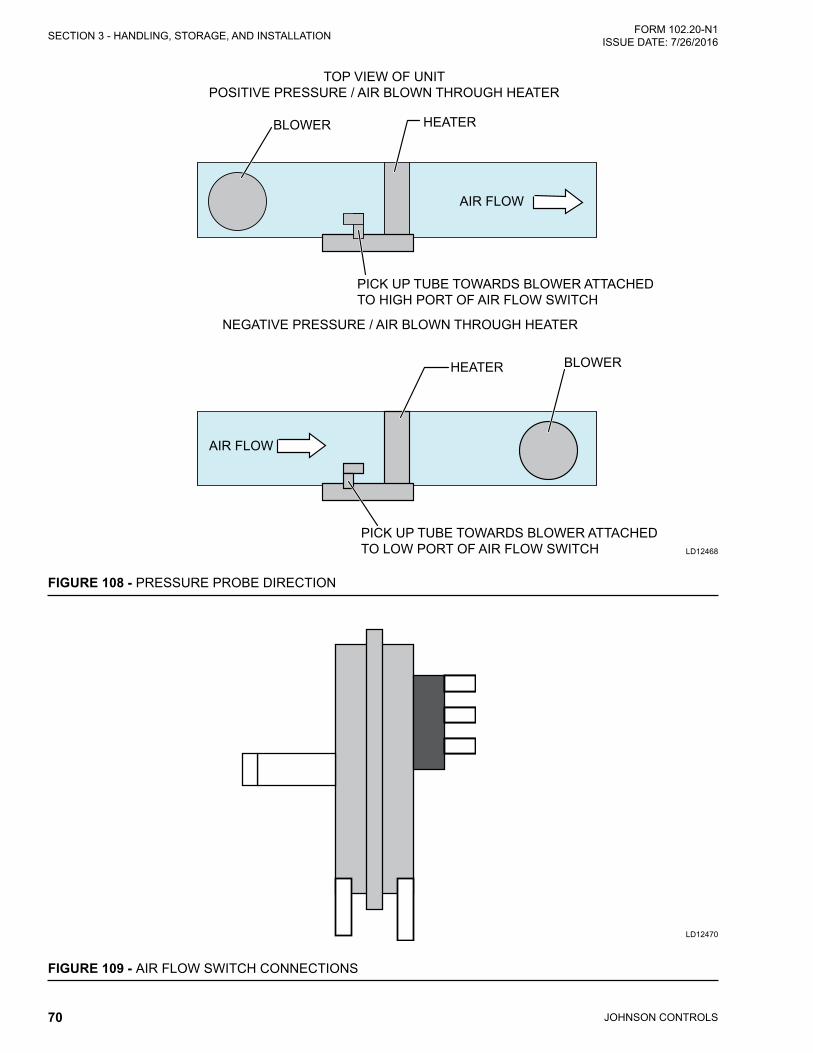
JOHNSON CONTROLS70
FORM 102.20-N1ISSUE DATE: 7/26/2016SECTION 3 - HANDLING, STORAGE, AND INSTALLATION
FIGURE 108 - PRESSURE PROBE DIRECTION
LD12468
BLOWER HEATER
AIR FLOW
BLOWERHEATER
AIR FLOW
PICK UP TUBE TOWARDS BLOWER ATTACHED TO HIGH PORT OF AIR FLOW SWITCH
PICK UP TUBE TOWARDS BLOWER ATTACHED TO LOW PORT OF AIR FLOW SWITCH
TOP VIEW OF UNITPOSITIVE PRESSURE / AIR BLOWN THROUGH HEATER
NEGATIVE PRESSURE / AIR BLOWN THROUGH HEATER
FIGURE 109 - AIR FLOW SWITCH CONNECTIONS
LD12470

JOHNSON CONTROLS 71
SECTION 3 - HANDLING, STORAGE, AND INSTALLATIONFORM 102.20-N1 ISSUE DATE: 7/26/2016
3
If it is incorrectly installed, remove the two screws holding the pressure probe in place and rotate 180° and reinstall. The airflow switch pressure port that is not connected to this pressure probe will be run to the exterior of the AHU to source a reference differential pressure.
In some situations it may be necessary to adjust this airflow switch setting to allow for proper operation as shown in Figure 109 on page 70. Take precautions to make sure that the airflow switch does not indicate false airflow.
Visually inspect the heater elements, prior to using the heater. If physical damage is evident, use a megohm test to validate the heater elements are safe use. If a minimum value of 10 megohms is not achieved, then any damaged elements or ceramic insulators must be replaced, prior to operation.
Electrical Installation1. Follow the wiring diagram on the inside of the ter-
minal box.
2. Make supply connections with copper wiring rat-ed for 75°C minimum.
3. If supply connections are for 250 volts or greater, all wiring must be insulated for 600 volts.
4. When making line connections to heater element terminalsforfinnedtubularheatersonly,applya1/4 in.wrenchto theflatsectionof the terminalimmediately below threads. Otherwise, damage to the terminal may result.
5. Size supply conductors for heaters rated less than 50 kW at 125% of rated load. On heaters rated 50 kW and greater, size the supply conductors at
TABLE 3 - MAXIMUM CURRENTAMPS WIRE SIZE
AWG/MCMAMPS WIRE SIZE
AWG/MCMAMPS WIRE SIZE
AWG/MCM125% 100% 125% 100% 125% 100%12 14 80 100 3 184 230 4/016 12 92 115 2 204 255 25024 10 104 130 1 228 285 30040 8 120 150 0 248 310 35052 65 6 140 175 2/0 268 335 40068 85 4 160 200 3/0 304 380 500
100% of rated load, if indicated on the wiring dia-gram. The line current for a single or three phase load is calculated as follows:
kW x 1000
Voltage
Single Phase Line Current =
kW x 1000
Voltage x 1.73
Three Phase Line Current =
6. Table 3 on page 71 shows the maximum cur-rent for 75°C copper wire with no more than three conductors in a raceway, which is based on the NEC - Table 310-16. The amperages are 125% and 100% wire sizes. If there are more than three conductors in a raceway, de-rate these amperages per Table 3 on page 71.
When connecting heaters with more than one stage, wire stage No. 1 so that it is the first stage on, and the last stage off.
7. Wire the heater so that it cannot operate unless air isflowingoverit,whichcanbeaccomplishedbyusingabuilt-inairflowswitchandaremoteinter-lock. See the wiring diagram located inside of the electric heater control panel for the method used with the heater and provide appropriate interlock wiring as illustrated.
8. If not supplied as part of the heater, install a line disconnect switch or main circuit breaker in ac-cordance with the NEC. Depending upon the heater’s location and accessibility, a built-in dis-connect switch may meet this requirement.
9. Check all electrical connections in the heater, in-cludingbothfieldandfactorymadeconnections,for tightness before operating the heater. After a short period of operation, check all connections again for tightness.

JOHNSON CONTROLS72
FORM 102.20-N1ISSUE DATE: 7/26/2016SECTION 3 - HANDLING, STORAGE, AND INSTALLATION
10. If the heater is wired to a heating/cooling thermo-stat, use a thermostat with isolating circuits to pre-vent possible interconnection of Class 2 outputs.
11. If the heating elements are divided into several sections with resistance wire between two or more sections, calculate the maximum kW per sq. ft as follows:
Number of heated sections x area of one heated section
Heater nameplate KW
ELECTRIC HUMIDIFIERIt's the installer's responsibility to wire this device be-cause this device is not included in the single point power option.
Figure 110 on page 72 represents a typical electric humidifier panel layout. The supply power knockout is located in the bottom of the electrical panel as shown in Figure 111 on page 72. All conduits beginning or ending on the inside of the pressurized or conditioned areas (i.e. AHU) must have the conduit openings sealed to prevent air from passing through it.
FIGURE 110 - LAYOUT OF TYPICAL HUMIDIFIER PANEL
LD11726
FIGURE 111 - SUPPLY POWER KNOCKOUTS
LD11727
KNOCKOUTS
All AHU penetrations must be sealed to prevent air and water leakage. Refer to Field Penetrations for Piping and Electrical Connections on page 63.
Field provided disconnects must provide circuit pro-tection according to the humidifier nameplate. All field wiring to the humidifier must be in accordance with NEC and local codes.
HUMIDIFIERControl wiring diagrams are located in the humidi-fier manufacturer's operator's manual, which can be found inside the control panel or it is attached. Factory package control drawings may not include humidifier points as shown in Figure 112 on page 72.
FIGURE 112 - HUMIDIFIER POINTS
LD11725
If the humidifier operator's manual cannot be located inside the humidifier, call Johnson Controls Airside Product Technical Support to get a copy of the elec-tronic version.

JOHNSON CONTROLS 73
SECTION 3 - HANDLING, STORAGE, AND INSTALLATIONFORM 102.20-N1 ISSUE DATE: 7/26/2016
3
Whenever possible, the piping should be brought down through outdoor Solution XT AHUs within the pipe chase as shown in Figure 114 on page 73.
FIGURE 114 - SOLUTION XT PIPE CHASE ENCLOSURE
LD09626a
Usable working clearance is approxi-mately the depth of the pipe chase. All dimensions are approximate and are not certified for construction. For outdoor Solution XT AHUs, the drain connec-tion is always on the opposite side of the pipe chase.
Penetrations through pipe chase floor must be flashed and sealed. Penetrations through panels must be sealed. Refer to the service manual for more information.
Where piping is insulated, insulation should not be in-stalled until after the flashing is completed.
LIGHTS FOR SOLUTION XT AHUsIf the Solution XT AHU is equipped with lights, the following parts are shipped loose for a tiered unit, as shown in Figure 113 on page 73
• Conduit (P/N 025-39024-001)
• SJO Cord (P/N 025-35746-01)
FIGURE 113 - SOLUTION XT AHU WITH LIGHTS TIER TRANSITION DRAWING
LD16602
PIPING CONNECTIONSInstall the Solution XT pipe chase before the piping is connected. Do not remove the bottom panel in the pipe chase.
When extended piping is present inside the Solution XT AHU, the field provided and installed insulation is required.

JOHNSON CONTROLS74
FORM 102.20-N1ISSUE DATE: 7/26/2016SECTION 3 - HANDLING, STORAGE, AND INSTALLATION
COIL PIPINGDo not test, clean and flush piping through this equipment.
Isolate this equipment from pressure test-ing of water, steam gas and air piping.
1. Consult the job specifications and submittaldrawings for specific piping requirements, coilconnection sizes and location. The AHU should be level to assure proper venting and draining of coils. The piping arrangements must provide for a balancedflow inmultiple coil installations asshown in Figure 115 on page 74.
FIGURE 115 - FACTORY COIL CONNECTIONS
LD06340
STEAM IN
CONDENSATE OUT
SAME END CONN
OPPOSITE END CONN
SDC COIL
AIR FLOW
2. Support all connecting piping independently of thecoils.Provideswingjointsorflexiblefittingsin all piping connections, particularly adjacent to heating coils to absorb expansion and contrac-tion strains because rigid piping connections can cause coil damage.
3. The coil supply and the return pipe connections are labeled. When attaching the piping to the coil header, make the connection only tight enough to prevent leaks. Excessive tightening may cause damage to the header.
Hold a backup wrench firmly on the coil con-nection so that when tightening the connecting piping, the torque is not transmitted to the coil header, which could damage the coil connection.
Application Notes - All connections are male pip-ing threaded except DX coils, which are soldered. Drain and vent taps on water coils are pipe thread, and shipped with plugs installed. These taps are installed approximately two in. back from the end of the thread-ed connections. Install the pipe for balanced flow and to assure even airflow.
Staggered CoilsStaggered coils in the AHUs equipped with an optional expanded cabinet will have connections brought to the AHU exterior for liquid or steam coils as shown in Fig-ure 116 on page 74 and Figure 117 on page 74. DX coils are not included.
The external connections are a threaded pipe or grooved pipe for the contractor to make his connections when the media is liquid, or a threaded pipe when the media is steam.
It's the installing contractor's responsibility to insulate the piping extensions inside the AHU.
FIGURE 116 - STAGGERED COIL - ANGLED WALLLD16561
FIGURE 117 - SPLIT COIL - OPPOSITE SIDE CONNECTIONS
LD16562

JOHNSON CONTROLS 75
SECTION 3 - HANDLING, STORAGE, AND INSTALLATIONFORM 102.20-N1 ISSUE DATE: 7/26/2016
3
Hot and Chilled Water Coils1. Connect the water supply to the header connec-
tion on the leaving air side of the coil to achieve thecounterflowofwaterandair.Thereturnpipewill be connected to the remaining coil connec-tion.
2. Install an air vent in place of the top pipe plug on the return header. To provide for drainage, install a drain line and shutoff valve in the supply near the coil, or in place of the plug in the supply con-nection as shown in Figure 118 on page 75 and Figure 119 on page 76.
Water Coil PerformanceFull steam pressure of water flow must be supplied at all times - modulating valves must not be used. A modulating steam valve or preheat coil can actually cause the coil to retain condensate due to a re-duced pressure in the coil thus exposing condensate in the tubes to freezing condi-tions. With modulating steam below 5 psig (valve closure) the steam may not be fully distributed in all of the tubes in the coil, causing the outer tube to cool abnormally. This will create thermal stress that can lead to possible "outer tube failure".
The temperature rise of the air (hot water coil) or tem-perature fall of the air (chilled water coil) leaving the coil is dependent on the:
• Airflowacrossthecoil,
• Gallonsofwaterflowthroughthecoil,and
• Entering water temperature into the coil.
Consult the job submittal form for more information.
FIGURE 118 - CHILLED WATER COIL CONNECTIONS EXAMPLE - (NOT FOR CONSTRUCTION)
LD12470
VENT
RETURN
RETURN
SUPPLY
SUPPLY
COIL
COIL
PT PLUG
DRAIN
UNIONGLOBE VALVE
GATE VALVE
PT PLUG
GATE VALVE W/ HOSE BIB
UNION
GLOBE VALVE
REDUCING TEE
CHILLED WATER SUPPLY
CHILLED WATER
RETURN
3 WAY CONTROL VALVE
ECCENTRIC REDUCER
STRAINER

JOHNSON CONTROLS76
FORM 102.20-N1ISSUE DATE: 7/26/2016SECTION 3 - HANDLING, STORAGE, AND INSTALLATION
FIGURE 119 - HOT WATER PIPING WITH 2-WAY VALVE EXAMPLE (NOT FOR CONSTRUCTION)
LD13791
VENT
RETURN
RETURN
SUPPLY
COIL
COIL
PT PLUG
DRAIN
UNIONGLOBE VALVE
GATE VALVE
PT PLUG
GATE VALVE W/ HOSE BIB
GLOBE VALVE
HOT WATER SUPPLY
HOT WATER RETURN
2 WAY CONTROL VALVE
ECCENTRIC REDUCER
STRAINER
SUPPLY
VENT
RETURN
RETURN
SUPPLY
COIL
COIL
PT PLUG
DRAIN
UNIONGLOBE VALVE
GATE VALVE
PT PLUG
GATE VALVE W/ HOSE BIB
GLOBE VALVE
HOT WATER SUPPLY
HOT WATER RETURN
3 WAY CONTROLDIVERTING VALVE
1 Inlet, 2 Outlets
ECCENTRIC REDUCER STRAINER
SUPPLY
FIGURE 120 - HOT WATER PIPING WITH DIVERTING VALVE EXAMPLE (NOT FOR CONSTRUCTION)
LD13792
UNION
REDUCING TEE

JOHNSON CONTROLS 77
SECTION 3 - HANDLING, STORAGE, AND INSTALLATIONFORM 102.20-N1 ISSUE DATE: 7/26/2016
3
WATER TREATMENTAny copper tube coils may be attacked by acid con-densate. Treat the coils with boiling water and CO2 to remove the condensate, and to assure longer tube life.
Freeze ProtectionChilled water, hot water, and steam coils can be dam-aged during freezing weather. Take the following pre-cautionary measures to prevent freezing:
• Positive coil freeze protection must be used in installations where any part of the water coil is subjected to temperatures of 32°F or lower, which may be accomplished by using a suitable anti-freeze solution. If the coil is not in use, it is rec-ommended to drain the coil completely, and blow dry the inside of the tubes with compressed air.
• Afterdraining,flushthecoilswithananti-freezesolution such as 50% glycol and 50% water, which will protect from the coil from freezing to approx-imately -35°F at sea level. Refer to ASHRAE and ARI guidelines for more information.
• During winter when shutdowns such as power failure, night and weekend shutdowns may occur, install the controls so the return air dampers go to the fully open position, and all fresh air dampers go to the fully closed position. A source of aux-iliary heat must be maintained inside the AHU cabinet.
• Other protection can include electromechanical switchesandconstantlyflowingwater;however,Johnson Controls will not be responsible for any coils damaged by freezing.
Steam CoilsThe operation of steam coils is dependent on airflow quantity and temperature as shown in Figure 121 on page 78. Consult the job submittal form for the in-formation specific to this AHU.
Steam Distributing CoilsUse the following instructions to clean the steam dis-tributing coils:
• Do not bush or reduce the coil return pipe size.
• Use a full size return pipe to the bottom of a dirt pocket. The supply pipe may be reduced at the coil connection, if necessary.
• Install the coil casing level with the return down. Acoilmustbesufficientlyelevatedtoallowa12in. minimum drop between the return connection on the coil and the trap. More than a two inch drop is required to protect the coil from freezing. The return main should be located below the trap.
Steam ControlContinuous steam supply ensures long coil life and minimizes potential trapping, venting and freezing problems. A rapid cycling of the modulating steam supply or a frequent on-off steam supply control re-sults in repeated thermal and piping stresses which will shorten the coil life. Modulating steam control valves must not be oversized, and must be carefully selected. A substantial variation in the supply pressure will re-quire installing a pressure-reducing valve ahead of the automatic control valve.
Light load operation with a modulated steam supply can be improved by the installation of a vacuum break-er check valve. An open relief line to the atmosphere from the return line near the coil is desirable, except on vacuum systems.
With a modulated steam supply, it is not practical to lift the condensate to an overhead return. Locate the coil well above the return, or provide condensate unit, or a boiler return trap below the coil.
Individual control valves are required on each coil in-stalled in series with respect to airflow. When a modu-lating steam valve supplies two or more coils in paral-lel, with respect to airflow, the piping must be designed to provide uniform steam distribution to each coil.
Steam TrapsUse the following information to select the correct steam trap.
• Float and Thermostatic (F and T) traps are recom-mended for all low or medium pressure applica-tions.
• Use thermostatic traps only for air venting, for outdoor applications where a F and T trap might be subject to freezing.
• Use bucket traps only for a non-modulated steam supply.
• Size the steam traps in accordance with the manu-facturer's recommendations (usually several times thesteadystatesteamflow).

JOHNSON CONTROLS78
FORM 102.20-N1ISSUE DATE: 7/26/2016SECTION 3 - HANDLING, STORAGE, AND INSTALLATION
• Use the actual operating conditions (coil pressure vs. return pressure) to select a trap.
• It is preferable to provide an individual trap for each coil, but a single trap may be used for coils operating in parallelwith respect to the airflow.Coilsinserieswithrespecttoairflowmustbesup-plied with individual traps.
• Locate the trap at least 12 in. below the coil return connection, and lower it when freeze protection is required. Do not attempt to lift condensate modu-lated steam supply.
FIGURE 121 - STEAM COIL PIPING ARRANGEMENTS
LD04887a
SUPPLY MAIN
DRIP TRAP FOR END OR LOW POINT OF SUPPLY MAIN
RETURN
MAIN
SUPPLY MAIN
SUPPLY
MAIN
SUPPLY MAIN
VENT TOATMOSPHERE CLOSE TO UNIT (NOT ON VACUUMSYSTEMS)
AIR FLOW
AIR FLOW
RETURN MAIN
RETURN MAIN
PITCHED IN CASING
STEAM COIL
STEAM COIL PITCHED IN CASING
12" MIN.
12" MIN.
SINGLE COILVERTICAL AIR FLOW
12" MIN. 12" MIN.
12" MIN.
COILS IN PARALLEL AIR FLOW MAY HAVE COMMON SUPPLY AND SINGLE TRAP (INDIVIDUAL COIL TRAP PREFERRED)
COILS IN SERIES AIR FLOW MUST HAVE INDIVIDUAL TRAPS AND CONTROL VALVES
RETURN MAINDIRT POCKET (FULL SIZE OF COIL CONN.)
F & T TRAP
VACCUM BREAKER 1/2" CHECK VALVE(OPTIONAL)
DIRT POCKET (FULL SIZE OF COIL CONN.)
VACUUM BRAKER 1/2" CHECK VALVE(OPTIONAL)
SYMBOLS FOR "SS" STEAM COIL PIPING ARRANGEMENTS
GATE VALVE
STRAINER
CONTROL VALVE (MODULATING OR TWO POSITION)
CHECK VALVE
FLOAT AND THERMOSTATIC TRAP

JOHNSON CONTROLS 79
SECTION 3 - HANDLING, STORAGE, AND INSTALLATIONFORM 102.20-N1 ISSUE DATE: 7/26/2016
3
VERTICAL TUBE INTEGRAL FACE AND BYPASS (VIFB) AND INTEGRAL FACE AND BYPASS (IFB)
The VIFB warranty will be voided if the return piping on the lower header (inlet and return on two-row header) does not include flexible connector(s), and if the lower header(s) bolts are not removed prior to use.
The VIFB lower header must be free to float as shown in Figure 122 on page 80. After the coil is piped, remove the yellow bolts to allow the header to float. Always back up the coil connections when installing the fittings.
Below 35°F, the VIFB, as shown in Figure 122 on page 80, or the IFB, as shown in Figure 123 on page 80, operates with full steam pressure or full water flow at all times, which prevents freeze-up and tem-perature stratification.
Shipping Bolts (VIFB Only)Return steam condensate headers or hot water supply and return headers are securely bolted to lower mount-ing brackets to prevent damage to the header and tubes during shipment and piping of the coils. Remove the bolts before applying steam or hot water, but after making all of the piping connections, as shown in Fig-ure 123 on page 80.
Piping Suggestions Read the following information before installing the piping.
• Supportthesteamandhotwaterfieldpipingsep-aratelyafter theflexibleconnector to isolate thepiping strains and additional expansion from the coils.
• Insulate the internal steam manifolds and piping.
• Size the steam traps three times the calculated condensate loading at the coil design conditions, based on the pressure differential across the trap, not the boiler pressure. Traps should be of types that pass condensate and air at saturated steam temperature. Inverted bucket traps should incor-porate thermostatic air vents.
• Make the return connection full size as required, and reduce only at the trap. Do not use the reduc-ing bushing on the coil return connection.
Flexible Connectors (VIFB Only)Return steam condensate headers, hot water supply, and return headers must be free to float. A flexible con-nector MUST be installed as close as possible to the coil, and parallel to the headers to accommodate a min-imum of 1/2 in. expansion movement of the headers.
Failure to install flexible connectors will restrict expansion of the headers, which can result in bowing of the tubes, bending of the fins, interfering with damper opera-tion, or eventually breaking the tubes.
Refer to the service manual for more information.
Freezing ConditionsAnti-stratification baffles are standard on all IFB and VIFB coils mounted in the AHUs.
The outside air and return air must be thoroughly mixed before passing over the coil. When freezing air enters only part of the coil, it creates a greater hazard than when the airflow entering the coil is a uniform temperature.
Coils used in series with respect to the airflow must have individual controls with ample space between the coils for sensing devices, when required. Coils with two or more rows are more sensitive to freezing than single row coils.
On outdoor AHUs, locate the low limit at least 24 in. downstream of the leaving edge of the VIFB/IFB cas-ing. The low limit element must cross the face and by-pass areas and be parallel to the headers.
Refer to the IFB/VIFB operator's manual (provided) for additional piping details. The Johnson Controls factory does NOT pipe the connections to the AHU exterior.

JOHNSON CONTROLS80
FORM 102.20-N1ISSUE DATE: 7/26/2016SECTION 3 - HANDLING, STORAGE, AND INSTALLATION
FIGURE 122 - IFB COIL (HORIZONTAL TUBES AVAILABLE WITH STEAM AND HOT WATER)
LD09630
FACE DAMPERS CLOSED
BYPASS OPEN
STEAM IN
STEAM OUT
ACTUATOR
FIGURE 123 - VIFB COIL (FACE-MOUNTED ACTUATOR SHOWN)
LD09631
SHIPPING BOLTS
FIGURE 124 - HOT WATER PIPING SCHEMATIC FOR 2-ROW COIL VIFB
LD09632
HOT WATER SUPPLY
HOT WATER RETURN
FLEXIBLE CONNECTOR DRAINS
AIR FLOW
VIFB COIL
3/4 in (19.1 mm) AUTOMATIC AIR VENT IN
TOP HEADER

JOHNSON CONTROLS 81
SECTION 3 - HANDLING, STORAGE, AND INSTALLATIONFORM 102.20-N1 ISSUE DATE: 7/26/2016
3
FIGURE 125 - HOT WATER PIPING FOR IFB
LD09633
3/4 in (19.1 mm) AUTOMATIC AIR VENT IN
TOP HEADER
HOT WATER RETURN
HOT WATER SUPPLY
DRAIN
AIR
FLOW

JOHNSON CONTROLS82
FORM 102.20-N1ISSUE DATE: 7/26/2016SECTION 3 - HANDLING, STORAGE, AND INSTALLATION
FIGURE 126 - STEAM PIPING FOR VIFB LD09634
(STEAM PRESSURE BELOW 15 PSIG (103.4 KPa)
STEAM MAIN DRIP TRAP STEAM MAIN
VACUUM BREAKER CHECK VALVE 1/2 in (12.7mm)-15"
AIR FLOWVIFB COILSTRAINER
AIR VENT TO ATMOSPHERE ON OPEN GRAVITY RETURN SYSTEM ONLY. MINIMUM 1 in (25.4mm) PIPE
T
T
STRAINER
RETURN MAIN
CHECK VALVE
COMBINATION FLOAT AND THERMOSTATIC TRAP
FLEXIBLE CONNECTOR
8 in (203.2mm)
8 in (203.2mm) MIN
NON-VENTING TRAPS(STEAM PRESSURE BELOW 15 PSIG (103.4 KPa)
1/2 in (12.7 mm)THERMOSTATIC TRAP FOR AIR REMOVAL
NON-VENTING TRAP NON-VENTING TRAP
CONDENSATE FLOW
CONDENSATE FLOW
3/4 in (19.1mm) AUTOMATIC AIR VENT
(STEAM PRESSURE ABOVE 15 PSIG (103.4 KPa)
VACUUM BREAKER CHECK VALVE 1/2 in (12.7 mm)- 15"
STEAM MAIN DRIP TRAP
STEAM MAIN
STRAINER
1/4 IN (6.4 MM)PETCOCK
CRACKED OPEN FOR CONTINUOUS
AIR VENTING
T
T
CHECK VALVE
STRAINER
INVERTED BUCKET TRAPRETURN MAINFLEXIBLE CONNECTOR INSTALLED PARALLEL TO COIL HEADER AND AS CLOSE AS POSSIBLE TO COIL CONDENSATE CONNECTION.
AIR FLOW
8 in (203.2mm)
8 in (203.2mm) MIN
VIFB COIL12 in MIN.
(304.8 mm)
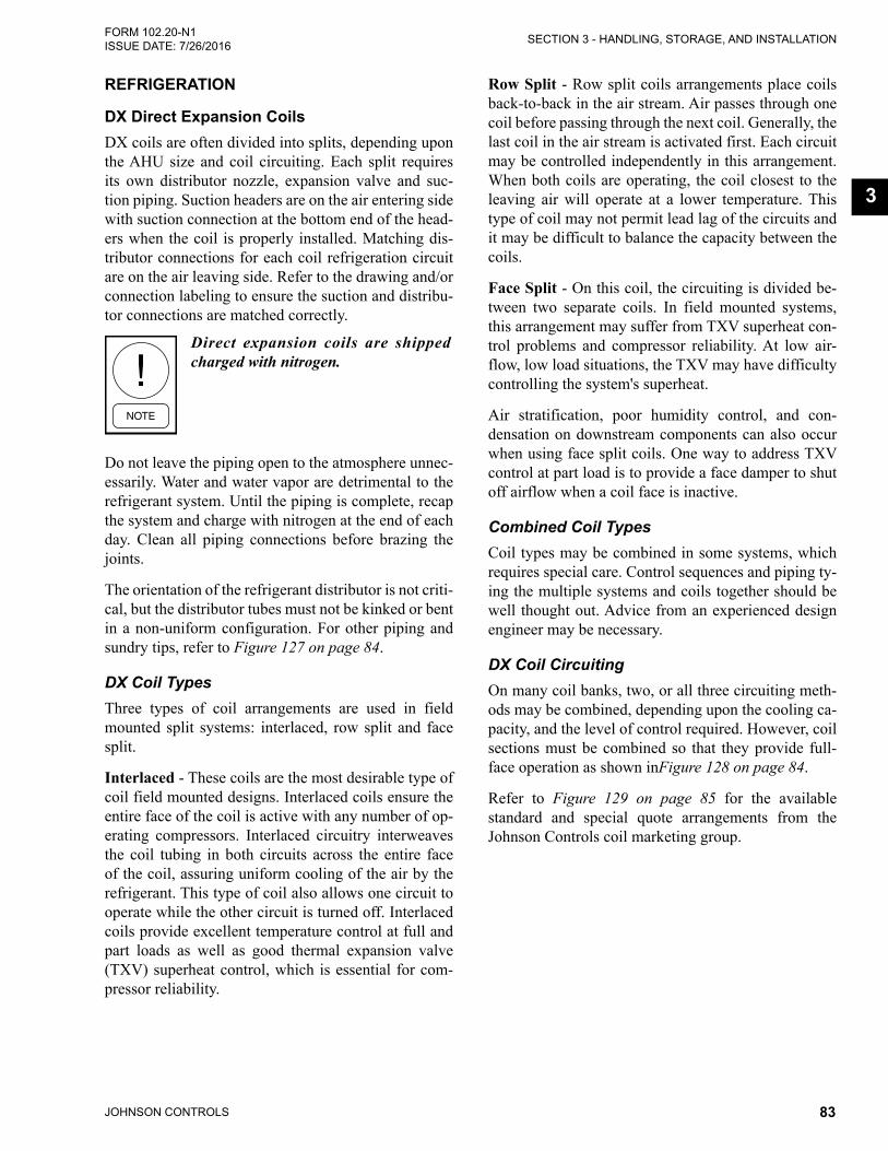
JOHNSON CONTROLS 83
SECTION 3 - HANDLING, STORAGE, AND INSTALLATIONFORM 102.20-N1 ISSUE DATE: 7/26/2016
3
REFRIGERATION
DX Direct Expansion CoilsDX coils are often divided into splits, depending upon the AHU size and coil circuiting. Each split requires its own distributor nozzle, expansion valve and suc-tion piping. Suction headers are on the air entering side with suction connection at the bottom end of the head-ers when the coil is properly installed. Matching dis-tributor connections for each coil refrigeration circuit are on the air leaving side. Refer to the drawing and/or connection labeling to ensure the suction and distribu-tor connections are matched correctly.
Direct expansion coils are shipped charged with nitrogen.
Do not leave the piping open to the atmosphere unnec-essarily. Water and water vapor are detrimental to the refrigerant system. Until the piping is complete, recap the system and charge with nitrogen at the end of each day. Clean all piping connections before brazing the joints.
The orientation of the refrigerant distributor is not criti-cal, but the distributor tubes must not be kinked or bent in a non-uniform configuration. For other piping and sundry tips, refer to Figure 127 on page 84.
DX Coil TypesThree types of coil arrangements are used in field mounted split systems: interlaced, row split and face split.
Interlaced - These coils are the most desirable type of coil field mounted designs. Interlaced coils ensure the entire face of the coil is active with any number of op-erating compressors. Interlaced circuitry interweaves the coil tubing in both circuits across the entire face of the coil, assuring uniform cooling of the air by the refrigerant. This type of coil also allows one circuit to operate while the other circuit is turned off. Interlaced coils provide excellent temperature control at full and part loads as well as good thermal expansion valve (TXV) superheat control, which is essential for com-pressor reliability.
Row Split - Row split coils arrangements place coils back-to-back in the air stream. Air passes through one coil before passing through the next coil. Generally, the last coil in the air stream is activated first. Each circuit may be controlled independently in this arrangement. When both coils are operating, the coil closest to the leaving air will operate at a lower temperature. This type of coil may not permit lead lag of the circuits and it may be difficult to balance the capacity between the coils.
Face Split - On this coil, the circuiting is divided be-tween two separate coils. In field mounted systems, this arrangement may suffer from TXV superheat con-trol problems and compressor reliability. At low air-flow, low load situations, the TXV may have difficulty controlling the system's superheat.
Air stratification, poor humidity control, and con-densation on downstream components can also occur when using face split coils. One way to address TXV control at part load is to provide a face damper to shut off airflow when a coil face is inactive.
Combined Coil TypesCoil types may be combined in some systems, which requires special care. Control sequences and piping ty-ing the multiple systems and coils together should be well thought out. Advice from an experienced design engineer may be necessary.
DX Coil CircuitingOn many coil banks, two, or all three circuiting meth-ods may be combined, depending upon the cooling ca-pacity, and the level of control required. However, coil sections must be combined so that they provide full-face operation as shown inFigure 128 on page 84.
Refer to Figure 129 on page 85 for the available standard and special quote arrangements from the Johnson Controls coil marketing group.

JOHNSON CONTROLS84
FORM 102.20-N1ISSUE DATE: 7/26/2016SECTION 3 - HANDLING, STORAGE, AND INSTALLATION
FIGURE 127 - TYPICAL PIPING AND SUNDRIES AT THE DX COIL
LD05171a
Insulated hot gas line from condensing unit pitch 1/2" per 10'in direction of flow
Must rise to the top of the coil and be high enough to slope to the compressors to facilitate oil return to the compressors.
Check Valves
Sight Glass
ThermalExpansion Valve
Sporlan Asc Hot Gas
Fitting
Sight Glass
Sporlan Asc Hot Gas Fitting
Thermal Expansion Valve
Txv Equalizer Line
Suction Line
Suction Line
Txv Equalizer Line
1-7/8"
45°
Ball Value
Liquid Line Drier
Liquid Line Solenoid Valve
Liquid Line From Condensing Unit
To insulate suction line condensing unit pitch 1/2" per 10' in direction of flow
Mount thermal expansion valve bulb on side of horizontal run of suction line as shown. Insulate bulb / line after clamping bulb to line.
Construct suction line P-trap from street fittings to maintain minimum trap volume.
FIGURE 128 - DX COIL CIRCUITING TYPES
LD03319b
Face Split Row Split Interlaced
Legend Refrigerant In
Refrigerant Out Warm Air Cold Air
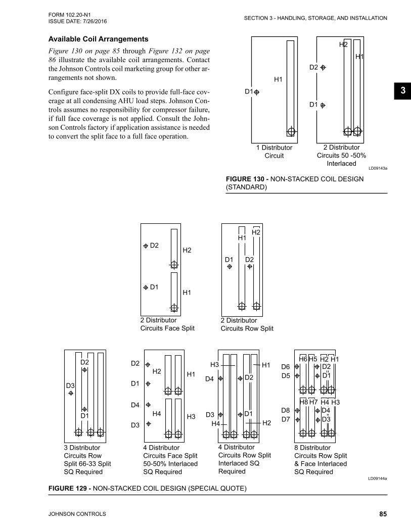
JOHNSON CONTROLS 85
SECTION 3 - HANDLING, STORAGE, AND INSTALLATIONFORM 102.20-N1 ISSUE DATE: 7/26/2016
3
Available Coil Arrangements Figure 130 on page 85 through Figure 132 on page 86 illustrate the available coil arrangements. Contact the Johnson Controls coil marketing group for other ar-rangements not shown.
Configure face-split DX coils to provide full-face cov-erage at all condensing AHU load steps. Johnson Con-trols assumes no responsibility for compressor failure, if full face coverage is not applied. Consult the John-son Controls factory if application assistance is needed to convert the split face to a full face operation.
FIGURE 129 - NON-STACKED COIL DESIGN (SPECIAL QUOTE)LD09144a
D2
D1H1
H2D1
H1H2
D2
D1
D2
D3 D1
D3
D2
D4H4
H2
H3
H1
H2
H1
D2
D1D3
D4
H3
H4
H1
H3
H2
H4
H5
H7
H6
H8
D5D6
D7D8
D1D2
D3D4
3 Distributor Circuits Row Split 66-33 Split SQ Required
4 Distributor Circuits Face Split 50-50% Interlaced SQ Required
4 Distributor Circuits Row Split Interlaced SQ Required
8 Distributor Circuits Row Split & Face Interlaced SQ Required
2 Distributor Circuits Face Split
2 Distributor Circuits Row Split
FIGURE 130 - NON-STACKED COIL DESIGN (STANDARD)
LD09143a
D1
H1
D2
D1
H1
H2
1 Distributor Circuit
2 Distributor Circuits 50 -50%
Interlaced

JOHNSON CONTROLS86
FORM 102.20-N1ISSUE DATE: 7/26/2016SECTION 3 - HANDLING, STORAGE, AND INSTALLATION
FIGURE 131 - STACKED COIL DESIGN (STANDARD)
LD09145a
D2
D1
D4
D3H4
H2
H3
H1
4 Distributor Circuits Face Split 50-50% Interlaced
FIGURE 132 - STACK COIL DESIGNS (SPECIAL QUOTE)LD09146
D1 H1
D1
D2
Single HDR Body
1 Distributor Circuit SQ Required
Single HDR Body
H1H2
2 Distributor Circuits 50 - 50% Interlaced SQ Required
D1
D2
H1
H2
2 Distributor Circuits Face Split SQ Required
Single HDR Body
H1
D1 D2
H2
2 Distributor Circuits Row Split SQ Required
Single HDR Body
D2
D3
D1
3 Distributor Circuits Row Split 66-33 Split SQ Required
4 Distributor Circuits Row Split Interlaced SQ Required
6 Distributor Circuits Face Split Interlaced SQ Required
8 Distributor Circuits Row Split & Face Interlaced SQ Required
Single HDR Body
D3
D4
H4
H3 H1
H2
D2
D1
D6
D5
H6
H5
H2
H4
H1
H3
D2
D4
D1
D3
D6D5
D8D7
H6
H8
H5
H7
H2
H4
H1
H3
D2
D4
D1
D3

JOHNSON CONTROLS 87
SECTION 3 - HANDLING, STORAGE, AND INSTALLATIONFORM 102.20-N1 ISSUE DATE: 7/26/2016
3
THERMOSTATIC EXPANSION VALVES (TXV) Each coil distributor circuit requires its own thermal expansion valves (TXV), and condensing AHU circuit requires its own liquid line solenoid valve (LLSV). Equip TXVs with external equalizer tubes that are field connected to the suction line. Size the valve according to the valve manufacturer's recommendations, allow-ing approximately 35 psi ( throughout the coil and dis-tributor at full load).
Do not oversize the valve. Follow the valve manufac-turer's instructions to find the thermostatic bulb. Proper expansion valve operation is necessary in order to real-ize the rated coil capacity.
When a DX type coil is operated with a suction temper-ature below 32°F, a buildup of frost will occur on the finned surface. It is not recommended to operate DX coils for air conditioning purposes at below freezing suction temperatures. If the full load operating point for the coil is selected at a safe temperature, a system analysis is required to check for the lowest probable suction temperature at light load conditions.
HOT GAS BYPASS (HGBP)When using discharge air temperature control or sys-tems with outside air economizer cooling, always in-clude hot gas bypass (HGBP). It is not as critical to use HGBP with return duct air temperature or suction pressure control, but it provides better capacity control at low loads.
The Venturi type distributor furnished with the DX coils may be ordered for field application of an HGPB. The connection may be made through a tee installed in the field between the expansion valve and distribu-tor. The system balance point and control adjustments must assure compressor cooling and avoid excessive compressor cycling. Refer to Guidelines for Proper Application Piping and Split Systems (Form 050.40-ES3) for compressor staging solutions.
DX COIL CIRCUITING AND STAGINGOn stacked coils, use a minimum of four coil circuits to achieve full face control as shown in Figure 133 on page 87. When the condensing AHU has two com-pressors per refrigerant circuit, one or two coil circuits may be used for each refrigerant circuit, depending upon the cooling capacity.
If one coil circuit is used as shown in Figure 134 on page 87, the LLSV and TXV must be sized to handle the full capacity of the refrigerant circuit. When two coil circuits are used per refrigerant circuit as shown in Figure 135 on page 87, each TXV should be sized to handle half of the capacity of the refrigerant circuit, and the LLSV should be sized to handle the full capac-ity of the refrigerant circuit.
2
4
1
31
2
FIGURE 133 - STACKED COIL CIRCUITINGLD09147a
Four Circuits Recommended
Two Circuits NOT Recommended
FIGURE 134 - ONE COIL CIRCUIT PER REFRIGERANT CIRCUIT
LD09148
100% Capacity
DX CoilCondensing Unit
FIGURE 135 - TWO COIL CIRCUIT PER REFRIGERANT CIRCUIT
LD09149DX Coil
Compressor #1
TXV
Compressor #2
TXV LLSV
Condensing Unit

JOHNSON CONTROLS88
FORM 102.20-N1ISSUE DATE: 7/26/2016SECTION 3 - HANDLING, STORAGE, AND INSTALLATION
When the condensing AHU has three compressors per circuit, use two coil circuits for each refrigerant circuit as shown in Figure 136 on page 88. Each coil circuit must have a dedicated TXV and distributor to handle one coil circuit, and the LLSV should be sized to han-dle the full capacity of the refrigerant circuit. Connect the HGPB line to all distributors in the coil circuit.
FIGURE 136 - THREE COMPRESSOR UNIT
LD09151
Compressor #1
TXVCompressor #3 Feeds Both Circuits
TXVCompressor #2
LLSV
Condensing Unit
In a stacked coil with four coil circuits piped to a con-denser with six compressors, the coil circuits would be face split and interlaced with two interlaced circuits on the lower coil section and two on the upper section as shown in Figure 137 on page 88.
1 - 3
4 - 6
4 - 6
1 - 3
FIGURE 137 - SIX COMPRESSOR UNITLD09153
Comp
TXV1
TXV3
TXV2
TXV4
Comp
Comp
CompDX Coils
LLSV1
LLSV2
Condensing Unit
When sizing TXVs, size the TXV for the refrigerant circuit tonnage divided by the number of DX coil liq-uid distributors, which should be equal to or smaller than the calculated value.
The first three compressors would be tied into LLSV1, TXV1 and TXV2, which would provide full face con-trol of the coil at the lowest cooling loads. Both dis-tributors on each coil circuit would include auxiliary side connectors for HGBP.
The second set of three compressors would be tied into LLSV2, TXV3 and TXV4 to maintain full-face control at higher loads. Refer to Guidelines for Proper Appli-cation Piping and Guidelines for Split Systems (Form 050.40-ES3) for compressor staging solutions.
Advantages of Multiple Control StagesThe more control stages used, the more precise the con-trol of the air temperature will be. Smaller incremental changes in capacity will result in a more consistent DX coil leaving air temperature, which will eliminate tem-perature swings in the conditioned space and improve the comfort level. But more importantly, a consistent space temperature is crucial to many process applica-tions.
The smaller changes in capacity that result from us-ing a greater number of control stages will also extend equipment life. The most important thing to remember is to maintain full-face control of the coil at all cooling loads. When row split coils are used, make sure that the first LLSV is energized with the last coil circuit in the leaving air stream, which is always the last one de-energized too.
MAINTAINING ADEQUATE AIRFLOW An electrical interlock between the AHU and the con-denser must be included for permissive run of the condenser. In addition, a differential pressure switch mounted across the supply fan must always be includ-ed to ensure airflow across the coil before the condens-ing AHU is energized. The condenser must never be operated unless the AHU fan is operating and air is flowing across the active coil. Insufficient airflow will result in liquid refrigerant returning to the condensing AHU, which could damage the compressors by liquid slugging or washing oil from the bearing surfaces.
In variable volume systems, the minimum acceptable airflow for fixed speed or variable air volume (VAV) systems is 350 FPM face velocity across each DX coil, as applied to split DX systems. Make sure that the TXV does not overfeed, because it could cause compressor failure.
The air velocity flowing through chilled water and di-rect expansion coils must not exceed specific recom-mended values to prevent water carryover.

JOHNSON CONTROLS 89
SECTION 3 - HANDLING, STORAGE, AND INSTALLATIONFORM 102.20-N1 ISSUE DATE: 7/26/2016
3
VAV SYSTEMSOverhead VAV systems are the preferred method of air distribution because they offer greater energy efficien-cy and better control of building diversity than constant volume systems (CVS). Unlike a CVS, in which the leaving air temperature is adjusted to satisfy the cool-ing load, the air temperature in a VAV system remains constant, and the air volume is varied to meet the cool-ing requirements.
A VAV system has four components:
1. AHUwithairflowcontrol(i.e.VariableFrequen-cy Drives (VFDs)),
2. VAV boxes,
3. Zone thermostats, and
4. Duct static pressure sensors.
These components must work together to provide good temperature control, and a comfortable environment.
The zone thermostats control the VAV boxes. As the zone temperature increases, the VAV boxes open to al-low greater airflow into the space, As the zone tem-perature decreases, the VAV boxes close to decrease the airflow to the space.
As the VAV boxes open and close, the static pressure in the ductwork changes. When a box opens, the duct static pressure decreases, and when a box closes, the duct static pressure increases. The duct static pressure sensor controls the AHU supply fan. Since an increase in duct pressure relates to a decrease in the required zone airflow, the supply fan volume decreases. Con-versely, a lower duct static pressure indicates a need for increased zone airflow; the supply fan volume increas-es. A change in supply air volume is accomplished us-ing a VFD or similar device.
In the AHU, a decrease in airflow through the DX coil will result in a corresponding decrease in the suction gas pressure while an increase in airflow will result in an increase in the suction gas pressure. Since the system is designed to maintain a constant suction gas pressure, the compressors will be turned on or off, as needed, to meet the increase or decrease in load demand. The sys-tem should be designed to operate smoothly, avoiding transients that could upset system balance and cause liquid flood back.
Problems can arise if the airflow decreases more quickly than the compressor control can respond to the load change. There-fore, airflow should never change at a rate faster than 3% per minute on VAV systems.
This limitation will promote stable control of the sys-tem and minimize fluctuations in zone temperature. Under any circumstances, a minimum of 350 FPM face velocity across the coil must be maintained for DX split systems.
DRAINS AND TRAPSWhere there is a risk of the liquid freez-ing in the trap, heat trace and insulate the traps to prevent blockage and/or damage.
Auxiliary drain pans may not require traps. If the trap is not in constant use, the water seal may evaporate, causing air passage into or out of the AHU. In these cases, it is recommended to cap the drain that allows the opening or closing of the drain, depending on its use.
Condensate Drain PipingThe majority of cooling coils are located in the AHUs, so that the supply air is drawn through them, which results in the condensate being subjected to negative (-) static pressure. Unless pressure equalization is pro-vided in the condensate drain, the air rushing back through the drain pipe will cause the condensate to build up in the drain pan.
As the AHU continues to operate, the accumulated wa-ter will be carried with the air stream, overfilling the drain pan, causing possible water leaks into the supply duct and/or causing water damage in the building. In-stall a trap to prevent this condensate water buildup as shown in Figure 138 on page 90.
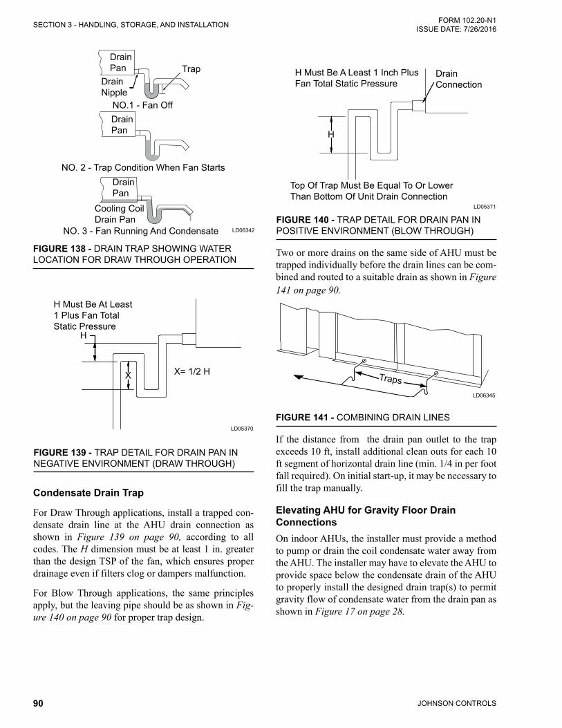
JOHNSON CONTROLS90
FORM 102.20-N1ISSUE DATE: 7/26/2016SECTION 3 - HANDLING, STORAGE, AND INSTALLATION
FIGURE 138 - DRAIN TRAP SHOWING WATER LOCATION FOR DRAW THROUGH OPERATION
LD06342
Drain Pan
Drain Nipple
Drain Pan
Drain Pan
NO.1 - Fan Off
NO. 2 - Trap Condition When Fan Starts
NO. 3 - Fan Running And Condensate
Cooling Coil Drain Pan
Trap
FIGURE 139 - TRAP DETAIL FOR DRAIN PAN IN NEGATIVE ENVIRONMENT (DRAW THROUGH)
LD05370
H Must Be At Least 1 Plus Fan Total Static Pressure
H
X= 1/2 HX
Condensate Drain Trap
For Draw Through applications, install a trapped con-densate drain line at the AHU drain connection as shown in Figure 139 on page 90, according to all codes. The H dimension must be at least 1 in. greater than the design TSP of the fan, which ensures proper drainage even if filters clog or dampers malfunction.
For Blow Through applications, the same principles apply, but the leaving pipe should be as shown in Fig-ure 140 on page 90 for proper trap design.
FIGURE 140 - TRAP DETAIL FOR DRAIN PAN IN POSITIVE ENVIRONMENT (BLOW THROUGH)
LD05371
H Must Be A Least 1 Inch Plus Fan Total Static Pressure
H
Top Of Trap Must Be Equal To Or Lower Than Bottom Of Unit Drain Connection
Drain Connection
Two or more drains on the same side of AHU must be trapped individually before the drain lines can be com-bined and routed to a suitable drain as shown in Figure 141 on page 90.
FIGURE 141 - COMBINING DRAIN LINES
LD06345
Traps
If the distance from the drain pan outlet to the trap exceeds 10 ft, install additional clean outs for each 10 ft segment of horizontal drain line (min. 1/4 in per foot fall required). On initial start-up, it may be necessary to fill the trap manually.
Elevating AHU for Gravity Floor Drain ConnectionsOn indoor AHUs, the installer must provide a method to pump or drain the coil condensate water away from the AHU. The installer may have to elevate the AHU to provide space below the condensate drain of the AHU to properly install the designed drain trap(s) to permit gravity flow of condensate water from the drain pan as shown in Figure 17 on page 28.

JOHNSON CONTROLS 91
SECTION 3 - HANDLING, STORAGE, AND INSTALLATIONFORM 102.20-N1 ISSUE DATE: 7/26/2016
3
DUCT CONNECTIONSThe duct must have positive seal to the AHU openings. Outdoor base rails are available in 3, 6, 8, or 10 in. height. It's the contractor's responsibility to provide the ductwork, which includes the base rail height, and sup-port it independently from the AHU.
Duct Connection GuidelinesThe duct connection guidelines are as follows:
• Duct connections to the AHU may be made di-rectly except when the AHU has external isola-tion. Then the duct connections should be made withflexiblematerial,andbeinstalledsotheyaresufficientlyloose.
• Duct connections should be designed and installed according to AMCA Standards 200 and 201, at a minimum.
• Duct turns and transitions must be made carefully to hold friction loss to a minimum. Avoid short turns. Duct elbows should contain splitters or turning vanes.
• The effective duct length connected to the fan or AHU discharge should run in a straight line for at least 2.5 equivalent discharge diameter for up to 2500 FPM fan outlet velocity and one additional diameter for each additional 1000 FPM fan outlet velocity.
• Ductwork should be no greater than 105.5% or no less than 85.5% of the discharge area. The slope of the transition elements should not be greater than 15% for converging elements, or greater than 7% for diverging elements.
• To find the equivalent discharge diameter, usethe following equation, where a = height, and b = width of the discharge:
EDD = 4ab/�
• A duct turn should be in the same direction as the fan rotation as shown in Figure 142 on page 91. Neverdeadheadthedischargeintotheflatsurfaceof a plenum.
FIGURE 142 - RECOMMENDED DISCHARGE DUCT ARRANGEMENT WHEN TURNS ARE REQUIRED
LD06335
Note: Make Turns In The Same Direction As Fan Rotation
Air
Flow
Air Flow
Air Flow
Air Flow
Effective Duct Length
Turning Vanes
Flanged Duct or SleevesTo use flanged ducts or sleeves, make sure there is ac-cess on all four sides to fasten the flange completely.
Connect the flanged ducts with self-drilling screws di-rectly to the AHU with a gasket or sealant between the AHU, and the duct flange as shown in Figure 143 on page 92. A flange may be dropped through the open-ing, if there is access to seal and fasten the flange to the AHU's interior surface.
Raw or Straight Edge Duct or SleevesThe duct opening on the AHU is located in a panel about 2 in. thick, which is suitable for attaching ducts.
If access is not available from the inside of the AHU, access may have to be gained from inside of the duct or sleeve.
Connect the raw or straight edge ducts with the self-drilling screws directly to the AHU with a gasket or sealant between the AHU and the duct flange as shown in Figure 143 on page 92.

JOHNSON CONTROLS92
FORM 102.20-N1ISSUE DATE: 7/26/2016SECTION 3 - HANDLING, STORAGE, AND INSTALLATION
FIGURE 143 - DUCT ARRANGEMENT FOR FLANGE AND RAW EDGE DUCTS
LD014087
Detail A
Sheet Metal Screw
Gasket Or Sealant
Flanged DuctRaw Edge Duct
Gasket Or Sealant
The performance ratings of coils will be met only if the airflow is uniform over the face of the coils. High air velocity spots on the coil may cause carryover of mois-ture from the coil. High or low air velocity areas of the coil will not deliver the published ratings. The duct connections must be designed to provide for uniform flow of air across the face of the coil. The entering duct must provide a smooth transition from any high veloc-ity effects. Stratifications of outside and return air, es-pecially where below freezing outside air enters, must be avoided to prevent coil freeze-up or nuisance low limit trips.
Sound and Vibration Transmission All roof-mounted AHUs generate some sound and vi-bration, which may or may not require special treat-ment of the air-conditioned space. The noise generated by the AHU depends on the following:
• Speed of the fan,
• Amount of air the fan is moving,
• Fan type, and
• Staticefficiencyofthefan.
In applications where sound and vibration transmis-sions may be objectionable, good acoustical engi-neering practices must be incorporated in the system design. On AHUs with return fans, it is important to consider the effects of sound transmission into the air-conditioned space.
When a AHU is used with a ceiling plenum return air system, sound may be transmitted from the AHU through the ceiling to the air-conditioned space. For such applications, install a sound absorption chamber near the AHU return air inlet. Various reference sourc-es are available regarding acoustic design.
Installing Top Discharge Outdoor AHU DuctFor outdoor XTO top duct connection, the installer is responsible for sealing the duct to the roof panel. The installer should not seal the duct to the unit opening.
Installing Front and Rear Discharge Outdoor AHU DuctUse the following instructions to install the front and rear discharge outdoor AHU duct.
• Building roof penetrations by ducts should utilize counterflashedcurbsasshowninFigure 144 on page 93.

JOHNSON CONTROLS 93
SECTION 3 - HANDLING, STORAGE, AND INSTALLATIONFORM 102.20-N1 ISSUE DATE: 7/26/2016
3
• Seal all penetrations into the ducts until water-tight. Use a minimum of duct penetration when attaching the supports.
• Provide adequate clearances between the ducts and roof penetration openings.
• Duct systems should not be pressurized without sufficienttimeforcuringthesealantsystems.Fol-low the sealant manufacturer's recommendations for applying the sealant.
• Support the ducts to avoid the transfer of duct weight across flexible connections as shown inFigure 145 on page 93.
• Horizontal ducts should be pitched and provided with drainage outlets.
• Install the ducts at a height sufficient to installroofingandflashing.Refer to theDuct Connec-tion Guidelines on page 91 for more informa-tion.
FIGURE 144 - DUCT PENETRATION OF ROOF
LD06494a
Upper Duct Section Not Continuous Through Roof
Sealant
Wood Nailer Norminal 2 X 4
Flashing Receiver
Lower Duct Section
Counterflashing
Curb
Base Flashing
Roofing Plies
Deck Cant Strip
Upper Section
FIGURE 145 - ROOF TO DUCT INSTALLATION (HORIZONTAL DISCHARGE)
LD06337b
Duct
Seams And Joint In Ducts
Roof Curb Front Or Rear
Discharge UnitDuct Wall Penetrations
Roof SupportElevate Bottom Of Duct

JOHNSON CONTROLS94
FORM 102.20-N1ISSUE DATE: 7/26/2016SECTION 3 - HANDLING, STORAGE, AND INSTALLATION
AIR FILTERSFilters MUST be in place in the filter frames before putting the AHU into operation to protect and keep the coils clean. Due to the wide variety of filters, it is not possible to cover all filter types. Refer to Figure 147 on page 95 for typical filter types.Multi-Sak Bag Filter
Multi-Pleat Elite 2 in. Pleated Filter
Multi-Pleat XL8 2 in. Pleated Filter
Multi-Cell 12 in. Rigid Filter
FIGURE 146 - TYPICAL FILTER TYPES
LD09650a
Install the filters in the correct orientation with regard to airflow and with pleats or pockets vertically, wher-ever possible. Refer to the Air Handling Units - Opera-tion and Maintenance Manual (Form 102.20-OM2) for more information.
Most AHUs will be shipped without filters. The John-son Controls sales office is responsible for ordering and delivering the filters in a timely manner. The con-tractor or commissioning agent must contact Johnson Controls regarding this issue because various filter types will have different lead times.
Filter latches as shown in Figure 147 on page 95, if required, will be shipped with the first filter ship-ment, except for HEPA filters. The HEPA filter latches will be attached to the filter racks inside of the AHU. Filter latches are not required for side load filter ar-rangements.
The contractor is responsible for installing the filters. and for freight claim, if the filters arrive damaged. Ad-dress other issues such as size, type, spares, replace-ments, or quantity with the Johnson Controls sales of-fice. Filter types are:
• Flat
• Angle
• Rigid
• Charcoal
• HEPA
Maintaining and Replacing FiltersEvery month, check the cleanliness of the filters and replace, if necessary. Replace the filters when the pres-sure, measured by a manometer, reaches the prescribed limits for the installation.

JOHNSON CONTROLS 95
SECTION 3 - HANDLING, STORAGE, AND INSTALLATIONFORM 102.20-N1 ISSUE DATE: 7/26/2016
3
SINGLE FILTER CLAMPS
(PERIMETER)
RED
DOUBLE FILTER
CLAMPS(T. SECTION)
SILVER
Used with 2 in. pre-�lter and SH Single Header Final Filters. P/N: 026-35788-702
Used with 2-in. (C86) and 4-in. (C89) pre-�lter combined with a Single Header Final Filter. C86 P/N: 026-35788-604. C89 P/N: 026-35788-605
Used with 2-in. and 4-in. pre-�lter combined with a double header (DH) �nal �lter. P/N: 026-35788-612
Used with 2-in. Pre-�lter Combined with a DH Final Filter. P/N: 026-35788-625
Used with 4 in. Pre-�lter Combined with a DH Final Filter. P/N: 026-35788-626
Used to Attach HEPA Filters to Holding Frame.HEPA Arm Filter ClipHEPA Arm Filter Clip
Used to Attach HEPA Filters to KOCH Holding Frame. Leg P/N: 029-22081-001. Latch P/N: 029-22081-002.
Used with 2-in. Pre-�lter Combined with a 4-in. Final Filter. P/N: 026-35788-609
FIGURE 147 - FILTER LATCHES
LD13303c

JOHNSON CONTROLS96
FORM 102.20-N1ISSUE DATE: 7/26/2016SECTION 3 - HANDLING, STORAGE, AND INSTALLATION
TABLE 4 - KOCH FILTER CLIPS - SINGLE FILTER APPLICATION
2 IN MICROMAX 4 IN MICROMAX MULTI-CELL FM SINGLE HEADER (SH) OR MULTI-SAK
MULTI-CELL SBM DOUBLE HEADER (DH)
P/N 026-35778-702 X XP/N 026-35778-604 XP/N 026-35778-612 X
TABLE 5 - KOCH FILTER CLIPS - PRE-FILTER / FINAL FILTER APPLICATION2 IN MULTI-PLEAT
ELITE OR CLEANABLE OR THROWAWAY AND MULI-CELL FM SINGLE
HEADER (SH) OR MULTI-SAK
2 IN MULTI-PLEAT ELITE OR CLEANABLE OR THROWAWAY AND
MULTI-CELL SBM DOUBE HEADER
4 IN MULTI-PLEAT XL8 AND MULTI-CELL FM SINGLE HEADER (SH) OR MULTI-SAK
4 IN MULTI-PLEAT ELITE
AND MULTI-CELL SBM DOUBLE
HEADER
P/N 026-35778-702 and 026-35778-604
X
P/N 026-35778-612 and 026-35778-625
X
P/N 026-35778-702 and 026-35778-605
X
P/N 026-35778-612 and 026-35778-626
X
Note: When filters are supplied by other companies, the filter clips are supplied as well.

JOHNSON CONTROLS 97
SECTION 3 - HANDLING, STORAGE, AND INSTALLATIONFORM 102.20-N1 ISSUE DATE: 7/26/2016
3
TABLE 6 - AAF CLIPS FOR FILTER FRAMES - SINGLE FILTER APPLICATION2 IN PERFECTPLEAT,
PREMIUM OR PREMIUM HM
4 IN AMAIR 300XVARICEL SINGLE HEADER (SH) OR
DRIPAK 2000
VARICEL DOUBLE HEADER (DH)
FILTER FRAME12X24 - 16 G GALVANIZED
P/N 026-35778-000 X XP/N 026-35778-007 XP/N 026-35778-006 X
FILTER FRAME24X24 - 16 G GALVANIZED
P/N 026-35778-000 X XP/N 026-35778-007 XP/N 026-35778-006 X
TABLE 7 - AAF PRE-FILTER/FINAL FILTER APPLICATION PERFECTPLEAT, PREMIUM OR HM
AND VARICEL SH OR DRIPAK 2000
PERFECTPLEAT, PREMIUM OR HM AND VARICEL DH
4 IN AMAIR 300X AND VARICEL SH OR
DRIPAK 2000
4 IN AMAIR 300X AND VARICEL DH
FILTER FRAME12X24 - 16 G GALVANIZED
P/N 026-35778-007 and 026-35778-000 X
P/N 026-35778-006 and 026-36339-001 X
P/N 026-35778-007, 026-35778-008 and 026-35778-000
X
P/N 026-35778-006 and 026-36339-000 X
FILTER FRAME 24X24 - 16 G GALVANIZED
P/N 026-35778-007 and 026-35778-000 X
P/N 026-35778-006 and 026-36339-001 X
P/N 026-35778-007, 026-35778-008 and 026-35778-000
X
P/N 026-35778-006 and 026-36339-000 X
Note: When filters are supplied by other companies, the filter clips are supplied as well.

JOHNSON CONTROLS98
FORM 102.20-N1ISSUE DATE: 7/26/2016SECTION 3 - HANDLING, STORAGE, AND INSTALLATION
Filter Installation Installing a 2 in. Pleated FilterUse the following instructions to install a 2 in. Multi-Pleat Elite filter into a 16 g galvanized holding frame with four latches (P/N 026-35788-702), as shown in Figure 147 on page 95.
1. Install one latch at each corner (4 corners) of the frame.Thelatchfitsintotworowsofthreeknock-outs. Use the row of knockouts closest to the gas-ketfornominal1in.filtersorfilterswitha13/16in. single header. Use the second set of knockouts fornominal2in.filters.
2. Insert the straight end of the latch between the two knockouts furthest from the corner.
3. Using a moderate amount of pressure, force the latch over the third knockout. The latch should now be trapped within the three knockouts, but should be able to freely rotate as shown in Figure 148 on page 98.
4. The latch installation should be complete.
FIGURE 148 - CORRECTLY INSTALLED LATCH PIN (P/N 026-35788-702)
LD10171
5. Install the other three latches into the corners.
6. Rotate all of the latches outward, and insert the filterintotheframe.
7. Grasp the circular end of the latch, and rotate it acrossthecornerofthefilter.
8. Pushtheendofthelatchtowardsthefilteruntilthelatch catches beneath the knockout on the frame.
9. Repeat the process with the remaining latches.
10. The filter should now be securely installed intothe frame as shown in Figure 149 on page 98.
FIGURE 149 - FULLY INSTALLED FILTER
LD10174
Installing a 4 in. Pleated FilterUse the following instructions to install a 4 in Micro-MAX filter into a 16 g galvanized holding frame with four latches (P/N 026-35778-604), as shown in Figure 147 on page 95.
1. Install one latch at each corner (4 corners) of the frame.Thelatchfitsintotworowsofthreeknock-outs. Use the row of knockouts closest to the gas-ketfornominal1in.filtersorfilterswitha13/16in. single header. Use the second set of knockouts fornominal2in.filters.
1. Insert the straight end of the latch between the two knockouts furthest from the corner.
2. Using a moderate amount of pressure, force the latch over the third knockout. The latch should now be trapped within the three knockouts, but should be able to freely rotate as shown in Figure 150 on page 98.
3. The latch installation should now be complete.
FIGURE 150 - CORRECTLY INSTALLED LATCH PIN (P/N 026-35788-604)
LD10177

JOHNSON CONTROLS 99
SECTION 3 - HANDLING, STORAGE, AND INSTALLATIONFORM 102.20-N1 ISSUE DATE: 7/26/2016
3
4. Install the other three latches into the corners.
5. Rotate all of the latches outward, and insert the filterintotheframe.
6. Grasp the loose end of the latch, and place it over thefilterframesothatthelatchsecuresthefilterinto the frame as shown in Figure 151 on page 99.
FIGURE 151 - PLACE THE END OF THE LATCH OVER THE FILTER FRAME
LD10179
7. Repeat the process with the remaining latches..
8. The filter should now be securely installed intothe frame.
Installing a Single Headered (SH) FilterUse the following instructions to install a 2 in. Single Headered (SH) filter into a 16 g galvanized hold-ing frame with four latches (P/N 026-24788-702), as shown in Figure 147 on page 95.
1. Install one latch at each corner (4 corners) of the frame.Thelatchfitsintotworowsofthreeknock-outs. Use the row of knockouts closest to the gas-ketfornominal1in.filtersorfilterswitha13/16in. single header. Use the second set of knockouts fornominal2in.filters
2. Insert the straight end of the latch between the two knockouts furthest from the corner.
3. Using a moderate amount of pressure, force the latch over the third knockout. The latch should now be trapped within the three knockouts, but should be able to freely rotate.
4. The latch installation should be complete.
5. Rotatethelatchesoutward,andinserttheSHfilterintotheframe.Insertthebulkofthefilterthroughthe frame, protruding out the backside. Only the headerofthefiltershouldbecontactingtheflangeof the frame.
6. Afterthefilterisplacedintotheframe,graspthecircular end of the latch and rotate it across the cornerofthefilter.
7. Pushtheendofthelatchtowardsthefilter,untilthe latch catches beneath the frame knockout.
8. Repeat the process with the remaining latches.
9. The filter should now be securely installed intothe frame as shown in as shown in Figure 152 on page 99.
FIGURE 152 - CORRECTLY INSTALLED CARTRIDGE FILTER
LD10148
Installing a 2 in. Pre-Filter Combined with a SH Final FilterUse the following instructions to install a 2 in. pre-filter combined with a SH final filter (Multi-Cell FM Single Header or Multi-Sak) into a 16 g galvanized holding frame with four latches (P/N 026-35778-604), as shown in Figure 147 on page 95.
1. Follow the instructions for theSHfilterson theprevious page, and then proceed with the follow-inginstructionsfor2in.pre-filters.
2. Insert the straight end of the latch between the two knockouts furthest from the corner.

JOHNSON CONTROLS100
FORM 102.20-N1ISSUE DATE: 7/26/2016SECTION 3 - HANDLING, STORAGE, AND INSTALLATION
3. Using a moderate amount of pressure, force the latch over the third knockout as shown in Figure 153 on page 100.
FIGURE 153 - CORRECTLY INSTALLED LATCH PIN (P/N 026-35788-604)
LD10496
4. Grasp the loose end of the latch, and place it over thepre-filter frame,so that the latchsecures thepre-filtertotheSHfilter.
5. Repeat the process with the remaining latches.
6. Thefiltersshouldnowbesecurely installed intothe frame as shown in Figure 154 on page 100.
FIGURE 154 - CORRECTLY INSTALLED CARTRIDGE WITH PLEATS
LD10160
Installing a Multi-Cell SBM Double Headered (DH) FilterUse the following instructions to install a Multi-Cell SBM double header (DH) filter (nominal 12 in.) into a 16 g galvanized holding frame with four latches (P/N 026-35788-612), as shown in Figure 147 on page 95.
1. Install the two latches on each side of the frame. not on the top or bottom. Refer to the sets of knockouts in Figure 155 on page 100 that should be used for the latches.
FIGURE 155 - CORRECT USE OF KNOCKOUTS
LD10150
2. Insert the straight end of the latch between the two knockouts furthest from the corner.
3. Using a moderate amount of pressure, force the latch over the third knockout.
4. The latch installation should be complete. The latch should now be trapped within the three knockouts.
5. Repeat the steps with the remaining latches. Note the orientation of the latch to the knockouts as shown in Figure 156 on page 100.
FIGURE 156 - CORRECT LATCHOUT/KNOCKOUT CONFIGURATION
LD10154
6. After the latches are installed, the frame should be configuredasshowninFigure 157 on page 101, which shows there are two latches per side, none on the top or bottom.

JOHNSON CONTROLS 101
SECTION 3 - HANDLING, STORAGE, AND INSTALLATIONFORM 102.20-N1 ISSUE DATE: 7/26/2016
3
FIGURE 157 - FRAME WITH FOUR LATCHES INSTALLED ON THE SIDES
LD10183
7. Insert the Multi-Cell SBM DH filter into theframe.Whileholdingthefilterintheframe,graspthe loop on the end of the latch, and pull it until it stretches over the header, and rests into the pre-drilled hole in the header as shown in Figure 158 on page 101.
8. Repeat this step with the remaining latches.
LD10184
FIGURE 158 - SPRING LATCH PULLED AND FASTENED IN FILTER HOLE
9. The filter should now be securely installed intothe frame.
Installing a 2 in. and 4 in. Pre-Filter Combined with a DH Final FilterUse the following instructions to install a 2 in or 4 in Multi-Pleat Elite or MicroMAX pre-filter combined with a Multi-Cell SBM DH (nominal 12 in. deep) final filter into a 16 g galvanized holding frame. Use the fol-lowinglatchestoinstallthefilterandpre-filter:
• Four spring latches (P/N 026-35788-612) to hold the Multi-Cell SBM DH into the frame,
• Four pre-filter latches (P/N 026-35788-625) tohold the 2 in. latch, and
• Four pre-filter latches (P/N 026-35788-626) toholdthe4inpre-filterontothefaceoftheMulti-CellSBMDHfilter.
1. Install the two latches on each side of the frame, not on the top or bottom.
2. Insert the straight end of the latch between the two knockouts furthest from the corner.
3. Using a moderate amount of pressure, force the latch over the third knockout.
4. The latch installation should now be complete. The latch should now be trapped within the three knockouts as shown in Figure 159 on page 101.
FIGURE 159 - CORRECT LATCHOUT/KNOCKOUT CONFIGURATION (P/N 026-35788-612)
LD10154
5. Repeat the steps with the remaining latches. Note the orientation of the latch to the knockouts as shown in Figure 159 on page 101.
6. Insert the Multi-Cell SBM DH filter into theframe.Whileholdingthefilterintheframe,graspthe loop on the end of the latch, and pull it until it stretches over the header, and rests into the pre-drilled hole in the header as shown in Figure 160 on page 102.

JOHNSON CONTROLS102
FORM 102.20-N1ISSUE DATE: 7/26/2016SECTION 3 - HANDLING, STORAGE, AND INSTALLATION
LD10184
FIGURE 160 - SPRING LATCH PULLED AND FASTENED IN FILTER HOLE
Installing Pre-Filter Latches 1. Toinstallthepre-filterlatches,slidetheendofthe
latch with a 180° turn over the edge of the header, as shown in Figure 161 on page 102. Install the latchattheapproximatemidpointofthefilterleg.Thepre-filterlatchshouldbeslidovertheheaderas shown in Figure 161 on page 102.
FIGURE 161 - INSTALLING PRE-FILTER LATCH
LD10163
2. Repeat the steps for the remaining pre-filter latches.
3. Placethepre-filteragainstthefaceoftheMulti-Cell SBM DH filter. The pre-filter latches mayhave to be re-positioned as shown in Figure 162 on page 102, to allow the proper placement of thepre-filter.
FIGURE 162 - POSITION PRE-FILTER IN FRONT OF FINAL FILTER
LD10165
4. Grasp the end of the pre-filter latch and springit,sothatitfitsovertheedgeofthepre-filteras shown in Figure 163 on page 102.
5. Repeat this step with the remaining latches.
FIGURE 163 - SPRING END OF LATCH
After placing all remaining pre-filter latches around the pre-filter; the finished assembly should look like the one shown in Figure 164 on page 102.
FIGURE 164 - COMPLETED ASSEMBLYLD10167
LD10190

JOHNSON CONTROLS 103
SECTION 3 - HANDLING, STORAGE, AND INSTALLATIONFORM 102.20-N1 ISSUE DATE: 7/26/2016
3
HEPA FILTERS
Koch HEPA Filter Frame
FILTER RETAINER CLIPS MUST BE
ATTACHED TO SIDES ONLY
HAT
AIRFLOW
AIRFLOW
FILTER CLIPS INSTALLED
FILTER CLIP INSTALLATION
SEE DETAIL A
FLAT SEALING SURFACE GASKET SEAL
HEPA FILTER
GASKET SEALDETAIL A
HOLDING FRAMEGASKET
LD13302
FIGURE 165 - INSTALLATION OF KOCH HEPA FILTERS

JOHNSON CONTROLS104
FORM 102.20-N1ISSUE DATE: 7/26/2016SECTION 3 - HANDLING, STORAGE, AND INSTALLATION
LD20623
FIGURE 166 - KOCH HF
Welded Bevel Seal Frame
Extruded Aluminum FramesThe bevel seal frame is a factory welded, extruded alu-minum frame developed specifically for High Efficien-cy Particulate Air (HEPA) filter installations. Standard bevel seal frames accommodate multiple sizes of gas-keted HEPA filters 11-1/2 in. deep as shown in Figure 165 on page 104.
Two Stage Gasket CompressionThe bevel seal frame features a two level sealing surface connected by a bevel, which causes the filter gasket to be compressed in two stages as clamping pressure is applied. The outer edge of the gasket is compressed to a greater degree than the inner portion of the gasket, as shown in Figure 168 on page 106.
Do not apply excess clamping pressure because the individual cells in the gasket material may fracture, causing the gasket to relax, allowing leakage.
FIGURE 167 - HEPA FILTER (CROSS SECTION)
LD06674a
2 in
2 in2 inT-Section Perimeter Section
Type H
Main Runner Perimeter Extrusion
VISUAL CONTROL FILTER CLAMPS
HEPA Filter ApplicationsVisual control clamps, as shown in Figure 166 on page 105, are designed to use with any conventional gas-keted HEPA filter. Located at midpoint of each filter edge, the calibrated spring-loaded clamps maintain up to 100 lb pressure against the filter at each clamping point. Four clamps, which have a 1-1/2 in. wide bearing sur-face, are used per filter to assure there is uniform pres-sure against the gasket.
Installing the Easy Clamp
No special tools are required to install the clamp prop-erly. Tighten the bolt head until it is flush with the clamp face to achieve the prescribed compression. Proper clamping pressure is created indefinitely by the calibrated spring.
Single filter clamps are used around the perimeter of the frame bank. Double clamps are used along main runners to secure a filter on either side of the T-section as shown in Figure 166 on page 105.

JOHNSON CONTROLS 105
SECTION 3 - HANDLING, STORAGE, AND INSTALLATIONFORM 102.20-N1 ISSUE DATE: 7/26/2016
3
FIGURE 168 - VISUAL CONTROL FILTER CLAMPS
LD06678
11-1/2 in Astrocel HCX
Single Filter Clamps
(Perimeter)
Double Filter Clamps
(T. Section)
Red
Silver
TABLE 8 - VISUAL CONTROL FILTER CLAMPS FOR HEPA FILTERS
PART NUMBER LATCH MODEL NUMBER LENGTH (L)
029-22081-000 Latch, HEPA Single 11-1/2 in029-22082-000 Latch, HEPA Double 11-1/2 in
DOUBLE FILTER CLAMPS
DOUBLE FILTER
CLAMPS
FIGURE 169 - INSTALLING HEPA FILTERLD09657
T-SECTIONS
SINGLE FILTER CLAMP
PERIMETER SECTION
T-SECTION

JOHNSON CONTROLS106
FORM 102.20-N1ISSUE DATE: 7/26/2016SECTION 3 - HANDLING, STORAGE, AND INSTALLATION
AIRFLOW
FIGURE 170 - INSTALLING WELDED BEVEL SEAL FILTER
LD06646a
Visual Control Clamp (Adjust bolt Head Flush With Clamp)
Spring
Ductwork
Cell Side
Media Pack
Gasket
Cell Side
Bevel Seal Frame
BevelRecessed Sealing Surface
Bevel Seal Frame(Perimeter Extrusion)

JOHNSON CONTROLS 107
FORM 102.20-N1 ISSUE DATE: 7/26/2016
The following factors can be used to convert from Eng-lish to the most common SI Metric values.
TABLE 9 - SI METRIC CONVERSION
MEASUREMENT MULTIPLY ENGLISH AHU BY FACTOR TO OBTAIN METRIC AHU
Capacity Tons Refrigerant Effect (ton) 3.516 Kilowatts (kW)
Power Horsepower 0.7457 Kilowatts (kW)
Flow Rate Gallons / Minute (gpm) 0.0631 Liters / Second (l/s)
LengthFeet (ft) 0.3048 Meters (m)
In.es (in) 25.4 Millimeters (mm)
Weight Pounds (lbs) 0.4538 Kilograms (kg)
Velocity Feet / Second (fps) 0.3048 Meters / Second (m/s)
Pressure DropFeet of Water (ft) 2.989 Kilopascals (kPa)
Pounds / Square In. (psi) 6.895 Kilopascals (kPa)
TEMPERATURETo convert degrees Fahrenheit (°F) to degrees Celsius (°C), subtract 32° and multiply by 5/9 or 0.5556.
Example: (45.0°F - 32°) x 0.5556 = 7.22°C
To convert a temperature range (i.e., a range of 10°F) from Fahrenheit to Celsius, multiply by 5/9 or 0.5556.
Example: 10.0°F range x 0.5556 = 5.6 °C range

P.O. Box 1592, York, Pennsylvania USA 17405-1592 800-861-1001 Subject to change without notice. Printed in USACopyright © by Johnson Controls 2016 www.johnsoncontrols.com ALL RIGHTS RESERVEDForm 102.20-N1 (716)Issue Date: July 26, 2016Supersedes: 102.20-N1 (615)


