
Solution Reference Network Design (SRND) for Cisco IPICS, … · Contents iv Solution Reference...
270
Americas Headquarters Cisco Systems, Inc. 170 West Tasman Drive San Jose, CA 95134-1706 USA http://www.cisco.com Tel: 408 526-4000 800 553-NETS (6387) Fax: 408 527-0883 Solution Reference Network Design (SRND) for Cisco IPICS Release 4.0(2) January, 2011 Text Part Number: OL-24067-01
Transcript of Solution Reference Network Design (SRND) for Cisco IPICS, … · Contents iv Solution Reference...
Americas HeadquartersCisco Systems, Inc.170 West Tasman DriveSan Jose, CA 95134-1706 USAhttp://www.cisco.comTel: 408 526-4000
800 553-NETS (6387)Fax: 408 527-0883
Solution Reference Network Design (SRND) for Cisco IPICS Release 4.0(2)January, 2011
Text Part Number: OL-24067-01

NOTICE. ALL STATEMENTS, INFORMATION, AND RECOMMENDATIONS IN THIS MANUAL ARE BELIEVED TO BE ACCURATE BUT ARE PRESENTED WITHOUT WARRANTY OF ANY KIND, EXPRESS OR IMPLIED. USERS MUST TAKE FULL RESPONSIBILITY FOR THEIR APPLICATION OF ANY PRODUCTS.
THE SOFTWARE LICENSE AND LIMITED WARRANTY FOR THE ACCOMPANYING PRODUCT ARE SET FORTH IN THE INFORMATION PACKET THAT SHIPPED WITH THE PRODUCT AND ARE INCORPORATED HEREIN BY THIS REFERENCE. IF YOU ARE UNABLE TO LOCATE THE SOFTWARE LICENSE OR LIMITED WARRANTY, CONTACT YOUR CISCO REPRESENTATIVE FOR A COPY.
The Cisco implementation of TCP header compression is an adaptation of a program developed by the University of California, Berkeley (UCB) as part of UCB’s public domain version of the UNIX operating system. All rights reserved. Copyright © 1981, Regents of the University of California.
NOTWITHSTANDING ANY OTHER WARRANTY HEREIN, ALL DOCUMENT FILES AND SOFTWARE OF THESE SUPPLIERS ARE PROVIDED “AS IS” WITH ALL FAULTS. CISCO AND THE ABOVE-NAMED SUPPLIERS DISCLAIM ALL WARRANTIES, EXPRESSED OR IMPLIED, INCLUDING, WITHOUT LIMITATION, THOSE OF MERCHANTABILITY, FITNESS FOR A PARTICULAR PURPOSE AND NONINFRINGEMENT OR ARISING FROM A COURSE OF DEALING, USAGE, OR TRADE PRACTICE.
IN NO EVENT SHALL CISCO OR ITS SUPPLIERS BE LIABLE FOR ANY INDIRECT, SPECIAL, CONSEQUENTIAL, OR INCIDENTAL DAMAGES, INCLUDING, WITHOUT LIMITATION, LOST PROFITS OR LOSS OR DAMAGE TO DATA ARISING OUT OF THE USE OR INABILITY TO USE THIS MANUAL, EVEN IF CISCO OR ITS SUPPLIERS HAVE BEEN ADVISED OF THE POSSIBILITY OF SUCH DAMAGES.
Cisco and the Cisco Logo are trademarks of Cisco Systems, Inc. and/or its affiliates in the U.S. and other countries. A listing of Cisco's trademarks can be found at www.cisco.com/go/trademarks. Third party trademarks mentioned are the property of their respective owners. The use of the word partner does not imply a partnership relationship between Cisco and any other company. (1005R)
Any Internet Protocol (IP) addresses and phone numbers used in this document are not intended to be actual addresses and phone numbers. Any examples, command display output, network topology diagrams, and other figures included in the document are shown for illustrative purposes only. Any use of actual IP addresses or phone numbers in illustrative content is unintentional and coincidental.
Solution Reference Network Design (SRND) for Cisco IPICS Release 4.0(2) © 2011 Cisco Systems, Inc. All rights reserved.
Solution OL-24067-01
C O N T E N T S
Preface ix
Overview ix
Revision History ix
Organization ix
Related Documentation x
Obtaining Documentation, Obtaining Support, and Security Guidelines x
C H A P T E R 1 Introducing Cisco IPICS 1-1
Cisco IPICS Benefits 1-1
Cisco IPICS Components 1-2
C H A P T E R 2 Cisco IPICS Component Considerations 2-1
Router Media Service 2-1
RMS Overview 2-2
RMS Components for Locations 2-2
Multiple Location Example 2-3
RMS Configuration Example 2-3
When is an RMS Required? 2-7
Allocation of RMS DS0 Resources 2-9
DSP Channel Optimization and Allocation 2-9
Examples of Hardware Configuration and Supported Voice Streams 2-10
Media Resource Allocation for the Dial Engine 2-10
Virtual Talk Groups 2-11
iiiReference Network Design (SRND) for Cisco IPICS Release 4.0(2)
Contents
Using the Cisco Hoot ‘n’ Holler Feature to Mix Channels in the RMS 2-15
Cisco IPICS Endpoint Scenarios 2-16
Remote IDC Users 2-24
Integrating Cisco IPICS with SIP Providers 2-29
Requirements for SIP Sessions 2-29
Default Dial Peer Scenarios 2-29
Dial Peer Use in Scenarios 2-30
Call Flow and Dial Peer Examples 2-31
When is an IDC Direct Dial prefix needed? 2-34
IDC Dialer Configuration and Integration with Unified Communications Platform 2-35
Configuring an IDC Dialer End Point on Cisco Unified Communications Manager 2-36
Configuring an IDC Dialer End Point on Cisco Unified Communications Manager Express 2-36
Configuring the IDC Dialer in the Cisco IPICS Administration Console 2-37
Cisco IPICS Mobile Client for Apple iPhone 2-38
DNS Configuration 2-38
Intranet Access Model 2-38
Internet/Intranet Access Model 2-39
Configuring DNS Settings on an iPhone. 2-40
Configuring a Cisco Multiservices Platform Devices as a DNS Server 2-40
Wireless Network Configurations 2-41
IOS-Based Wireless Configuration 2-41
LWAPP-Based Wireless Configuration 2-45
Wireless Configuration on an iPhone 2-46
Cisco Unified IP Phones 2-47
Cisco Unified Communications Manager Configuration Overview 2-47
Cisco Unified Communications Manager Express Configuration Overview 2-47
ivSolution Reference Network Design (SRND) for Cisco IPICS Release 4.0(2)
OL-24067-01
Contents
Text to Speech 2-48
Installing Nuance TTS 2-49
Configuring a Language Pack Other than en-US 2-50
TTS Configuration and Operation 2-51
Video Considerations 2-53
Using Video from Cisco Video Surveillance Manager 2-53
Guidelines for Video 2-54
Notification 2-55
Email Notification Action 2-56
IP Phone Text Notification Action 2-56
Dial Notification Action 2-57
Talk Group Notification Action 2-57
Dial Engine Script Notification 2-58
Alert Notification Action 2-58
External (Bulk) Notification 2-58
C H A P T E R 3 Cisco IPICS LMR Gateway Configurations 3-1
Interfacing the Cisco IPICS LMR Gateway with Land Mobile Radios 3-2
Cabling 3-2
Analog E&M Interface 3-4
Analog E&M signaling Types 3-4
Cisco IOS LMR Gateway Configurations 3-7
Determining Correct Cisco IOS Radio Control 3-8
Required Baseline LMR Gateway Configuration 3-8
VAD Operated Signaling Configuration 3-8
COR/COS Operated Signaling Configuration 3-10
Important Considerations When Deploying Cisco IPICS with Tone Controlled Radios 3-12
Understanding Tone Control Signaling in Cisco IPICS 3-12
Tone Signaling with Radios 3-15
vSolution Reference Network Design (SRND) for Cisco IPICS Release 4.0(2)
OL-24067-01
Contents
Using the IDC with a Tone Controlled Radio Channel 3-17
Requirements for Tone Remote Radio Configuration in a Cisco IPICS Deployment 3-18
Understanding Descriptor Files 3-19
Providing Tone Sequences to Radios Without Using the Cisco IPICS Tone Remote Feature 3-22
Tone Controlled Radio Channels in VTGs 3-24
Troubleshooting Techniques 3-24
IDC Caveats 3-37
Configuration Examples for Manual Tone Control Operated Signaling Scenarios 3-39
2-Wire Tone Control Configuration for Single Frequency 3-39
4-Wire Tone Control Configuration for Single Frequency 3-40
2-Wire Tone Control Configuration for Two-Ten Frequencies 3-41
Pooled Radios 3-51
Configuring and Allocating Pooled Resources 3-52
Pooled Resource Allocation 3-52
Determining How many Pooled Radios to Configure 3-53
Optimizing Priorities for Trunked Networks and Wide Area Systems 3-53
Serial Radio Control 3-53
Setting up and Configuring Serial Control for EF Johnson Radios 3-54
Required Components 3-54
Connecting an EF Johnson Donor Radio to an LMR Gateway 3-55
Configuring the LMR Gateway for E&M Communications with EF Johnson Radios 3-56
Configuring the LMR Gateway for Serial Radio Control 3-57
Setting up and Configuring Serial Control for Sprint Nextel (iDEN) Handsets 3-58
Required Components 3-59
Connecting a Sprint Nextel (iDEN) Handset to an LMR Gateway 3-59
Configuring a Sprint Nextel (iDEN) Handset 3-60
viSolution Reference Network Design (SRND) for Cisco IPICS Release 4.0(2)
OL-24067-01
Contents
Configuring the LMR Gateway for E&M Communication with Sprint Nextel (iDEN) Handsets 3-60
Configuring the LMR Gateway for Serial Radio Control 3-62
Trunked Radio Optional Workaround 3-63
Trunked Radio Feedback Tones 3-63
Trunked Radio Hybrid Configuration 3-64
Analog Tap Recording Configuration 3-67
Recording Multicast LMR Traffic 3-68
Recording Tap Cisco IOS Configuration 3-68
C H A P T E R 4 Cisco IPICS Infrastructure Considerations 4-1
WAN Considerations 4-2
Multicast Routing 4-2
Bandwidth Planning 4-4
Codecs 4-4
Choosing a Codec 4-4
Calculating Codec Bandwidth Use 4-5
cRTP, Variable-Payload Sizes and Aggressive VAD 4-7
RTP Header Compression 4-7
Adjustable Byte Size of the Voice Payload 4-7
Aggressive Voice Activity Detection 4-8
Mixing Voice Streams 4-8
Redundant RMS Configuration 4-9
Topology 4-9
Cabling 4-11
Routing Overview 4-12
Normal Operation 4-12
Failure Mode 4-12
Fail Back Mode 4-12
Sample Configuration for RMS1 and GW1 4-13
viiSolution Reference Network Design (SRND) for Cisco IPICS Release 4.0(2)
OL-24067-01
Contents
Failure Scenario Behavior 4-13
Caveats 4-14
Router Configurations 4-14
GW1 Configuration 4-14
GW2 Configuration 4-17
GW3 Configuration 4-19
RMS1 Configuration 4-24
RMS2 Configuration 4-28
High Availability Considerations 4-32
Node Manager 4-32
Database Replication 4-33
SSH Public Keys and TLS Certificates 4-33
Deployment of Active and Standby Servers 4-33
HA Considerations for the IDC 4-34
Quality of Service 4-34
QoS Overview 4-34
Cisco IOS Queuing Techniques 4-35
IP RTP Priority 4-35
Low Latency Queuing 4-36
QoS with Frame Relay 4-36
Frame Relay Broadcast Queue 4-38
QoS with Point-to-Point Connections 4-44
QoS for a LAN 4-45
QoS at the WAN Edge 4-45
Policing 4-46
Queuing 4-46
Trust Boundaries 4-46
VPN in Deployment Scenarios 4-48
Port Utilization 4-49
Guidelines for Using IP Multicast Addresses with Cisco IPICS 4-50
viiiSolution Reference Network Design (SRND) for Cisco IPICS Release 4.0(2)
OL-24067-01
Contents
Multicast and Unicast 4-51
QOS Policy Considerations 4-51
Securing the Cisco IPICS Infrastructure 4-51
Secure Socket Layer 4-51
Cisco Security Agent 4-51
Firewalls and Access Control Lists 4-52
Other Security Recommendations 4-52
Cisco IPICS Network Management System 4-52
Managing the Overall Network 4-53
C H A P T E R 5 Understanding Dial Peers 5-1
Dial Peer Call Legs 5-1
Inbound and Outbound Dial Peers 5-2
Destination Pattern 5-3
Session Target 5-3
Configuring Dial Peers for Call Legs 5-4
Matching Inbound and Outbound Dial Peers 5-4
C H A P T E R 6 Cisco IPICS Licensing and Sizing Guidelines 6-1
Resource and License Usage 6-1
DS0 Usage 6-1
Additional Planning and Sizing Guidelines 6-1
Dial Port Licensing Details 6-3
C H A P T E R 7 Cisco IPICS Deployment Models 7-1
Single Site Model 7-1
Benefits of the Single Site Model 7-2
Best Practices for the Single Site Model 7-2
ixSolution Reference Network Design (SRND) for Cisco IPICS Release 4.0(2)
OL-24067-01
Contents
Multiple Site Model 7-2
MPLS with Multicast VPNs 7-3
MPLS Terminology 7-4
MVPN Basic Concepts 7-4
VPN Multicast Routing 7-5
Configuring the Provider Network for MVPN 7-5
Verifying the Provider Network for MVPN 7-7
Optimizing Traffic Forwarding: Data MDT 7-9
Verifying Correct Data MDT Operation 7-9
Multicast Islands 7-10
Multicast over GRE 7-11
M1:U12:M2 Connection Trunks 7-13
Multicast Singularities 7-21
C H A P T E R 8 High Latency and Low Bandwidth Interconnection 8-1
Supported Deployment Solutions 8-2
Central Site Server Solution 8-2
Remote Locations Solution 8-3
M1:U12:M2 Configuration Examples 8-3
Requirements and Support Information 8-4
Performing Additional Configurations on the Cisco IPICS Server 8-5
Updating the RMS Configuration 8-5
Adjusting ARP Commands 8-6
Disabling the RMS Comparator 8-6
Merging the Configuration 8-6
Disabling the IDC Upload Activity Log Frequency 8-7
Adjusting Internet Explorer Browser Settings 8-7
Performance Guidelines 8-8
xSolution Reference Network Design (SRND) for Cisco IPICS Release 4.0(2)
OL-24067-01

Contents
G L O S S A R Y
I N D E X
xiSolution Reference Network Design (SRND) for Cisco IPICS Release 4.0(2)
OL-24067-01

Contents
xiiSolution Reference Network Design (SRND) for Cisco IPICS Release 4.0(2)
OL-24067-01
Preface
OverviewThis Solution Reference Network Design (SRND) document provides design considerations and guidelines for deploying Cisco IPICS release 4.0(2). This document should be used with the related documentation that the “Related Documentation” section on page x describes.
For other design documents, go to this URL:
http://www.cisco.com/go/srnd
Revision HistoryThis document may be updated at any time without notice. Check the Cisco.com website periodically for documentation updates.
OrganizationThis manual is organized as follows:
Chapter 1, “Introducing Cisco IPICS” Describes the advantages and benefits that Cisco IPICS offers and introduces the primary components that make up a Cisco IPICS deployment
Chapter 2, “Cisco IPICS Component Considerations”
Provides information about various Cisco IPICS components
Chapter 3, “Cisco IPICS LMR Gateway Configurations”
Describes configurations needed to use land mobile radios with Cisco IPICS
Chapter 4, “Cisco IPICS Infrastructure Considerations”
Provides information about network infrastructure considerations that you must be aware of when you deploy Cisco IPICS
Chapter 5, “Understanding Dial Peers” Provides an overview of dial peers, which will help you understand how Cisco IPICS operates
ixSolution Reference Network Design (SRND) for Cisco IPICS Release 4.0(2)
OL-24067-01
Preface
Related DocumentationTo access the documentation suite for Cisco IPICS, go to the following URL:
http://www.cisco.com/en/US/products/ps7026/tsd_products_support_series_home.html
The following Cisco IPICS documentation is available:
• Cisco IPICS Server Administration Guide, Release 4.0(2)—Contains information about the key configuration, operation, and management tasks for the Cisco IPICS server.
• Cisco IPICS Server Installation and Upgrade Guide, Release 4.0(2)—Describes how to install, configure, and upgrade the Cisco IPICS server software and Cisco IPICS operating system.
• Cisco IPICS Dispatch Console User Guide, Cisco IPICS Release 4.0(2)—Describes how to install, configure, manage, and operate the Cisco IPICS Dispatch Console (IDC) application
• Cisco IPICS API Reference Guide, Cisco IPICS Release 4.0(2)—Provides the information that is required to understand and use the Cisco IPICS application programming interface (API).
• Release Notes for Cisco IPICS Release 4.0(2)—Contains a description of the new and changed features, important notes, caveats, and documentation updates for this release of Cisco IPICS.
• Cisco IPICS Compatibility Matrix—Contains information about compatible hardware and software that is supported for use with Cisco IPICS.
• Cisco IPICS 4.0(2) Resources Card (Documentation Locator)—Provides a summary of the documentation that is available for this release of Cisco IPICS.
Cisco also provides a wide variety of other documentation that provides related information about Cisco IPICS components and the configuration of an infrastructure that supports Cisco IPICS. References to related documentation is provided throughout this manual as appropriate.
Obtaining Documentation, Obtaining Support, and Security Guidelines
For information about obtaining documentation, obtaining support, providing documentation feedback, security guidelines, and recommended aliases and general Cisco documents, see the monthly What’s New in Cisco Product Documentation, which also lists all new and revised Cisco technical documentation, at:
http://www.cisco.com/en/US/docs/general/whatsnew/whatsnew.html
Chapter 6, “Cisco IPICS Licensing and Sizing Guidelines”
Explains how Cisco IPICS uses licensable features and provides information about resource use and system sizing
Chapter 7, “Cisco IPICS Deployment Models” Describes the deployment models for Cisco IPICS
Chapter 8, “High Latency and Low Bandwidth Interconnection”
Describes deployment models that use high latency and low bandwidth interconnections
xSolution Reference Network Design (SRND) for Cisco IPICS Release 4.0(2)
OL-24067-01
Solution Reference NeOL-24067-01
C H A P T E R 1
Introducing Cisco IPICSCisco IP Interoperability and Collaboration System (Cisco IPICS) is an intelligent platform that controls media and information, enabling intra- and inter-organizational communication, interoperability, and operational efficiencies. By taking advantage of IP standards and protocols, Cisco IPICS bridges communications from existing and proprietary radio networks to IP networks and devices such as the IPICS Dispatch Console (IDC), and supported models of the Cisco Unified IP Phone.
This chapter provides an overview of Cisco IPICS. It describes the advantages and benefits that Cisco IPICS offers to various organizations. It also introduces the primary components of a Cisco IPICS deployment.
This chapter includes these topics:
• Cisco IPICS Benefits, page 1-1
• Cisco IPICS Components, page 1-2
Cisco IPICS BenefitsCommunications interoperability, data integration, and true event- and incident-based contextual collaboration between agencies and organizations are important requirements in many markets, including the following segments:
• Enterprise (operations and safety and security)
• Commercial
• Financial Services
• Retail
• Education
• Healthcare
• Utilities
• Oil and gas
• Public safety
• Transportation
• Military/Defense
• Government
• Service provider
1-1twork Design (SRND) for Cisco IPICS Release 4.0(2)
Chapter 1 Introducing Cisco IPICSCisco IPICS Components
Organizations in these market segments typically deploy several wired networks and wireless networks to achieve their business and service goals. However, such disparate solutions often do not support interoperability and collaboration, which can affect operational efficiency and customer satisfaction.
Examples of such disparate networks include:
• Legacy push-to-talk (PTT) radio networks (analog or digital at different frequencies) that are used for voice communications within groups. Communication is usually restricted within a specified group or network because of radio frequency (RF) limitations and proprietary protocols.
• Traditional hoot bridges that are connected over time-division multiplexing (TDM) circuits. These deployments cannot provide audit trails and they do not seamlessly integrate with other PTT or Voice over IP (VoIP) networks. In addition, they do not offer the mobility and serviceability that an IP deployment provides.
• VoIP networks that are used to carry packetized voice on wired or wireless IP phones or on other IP clients. These clients do not interact with the PTT services.
For organizations that use disparate networks, the Cisco IPICS solution provides the following benefits:
• Incident management framework graphical user interface (GUI)—Facilitates tasks that are associated with operations and command and control.
• Easy-to-use installation, management, and operational features—Enables a migration path to more robust IP applications, devices, and IP-based solutions to achieve greater operational efficiencies.
• Effective solution—Streamlines operations, and command and control while protecting investments in deployed radio networks or legacy hoot bridges and applications.
• Efficient deployment—Leverages current IP infrastructure with minimal upgrades required, decreasing total cost of ownership.
• Resiliency—Eliminates communications silos and single points of failure.
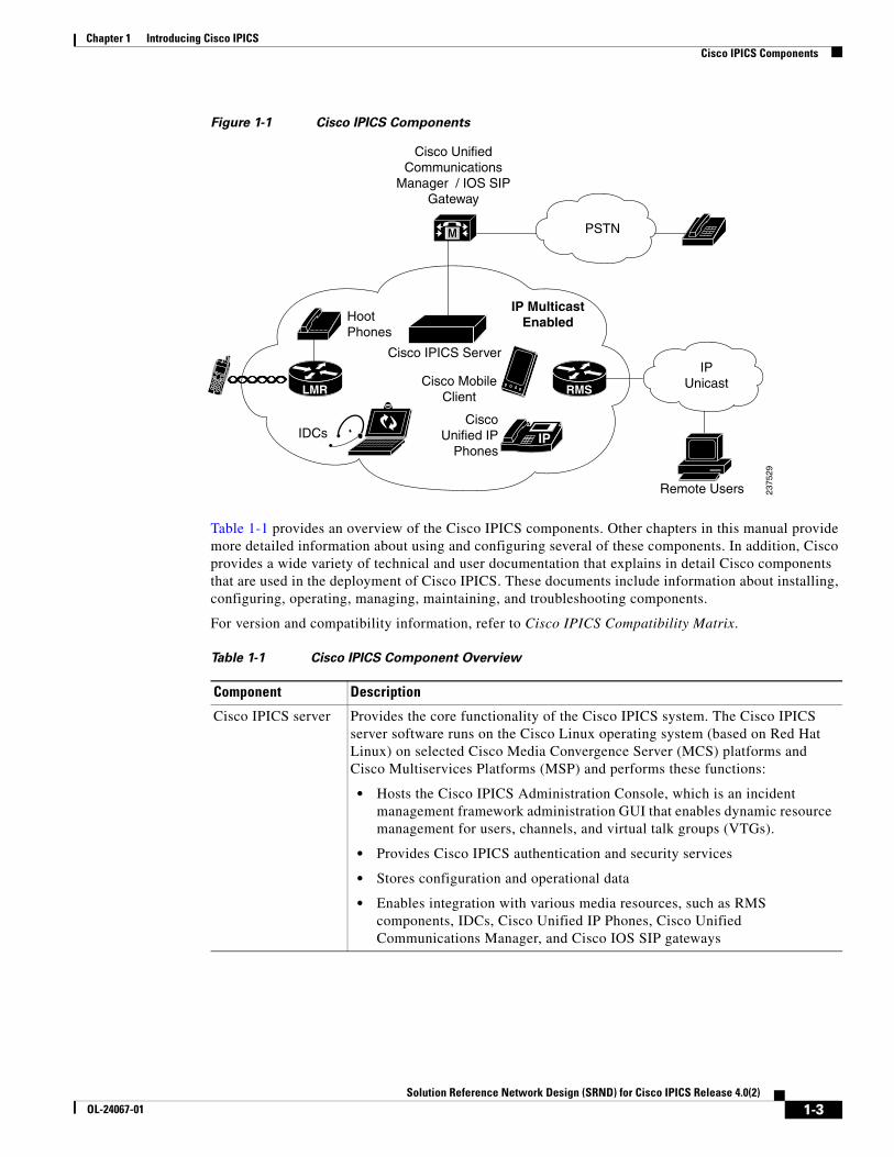
Cisco IPICS ComponentsA Cisco IPICS deployment involves several hardware and software components to enable true interoperability and collaboration. Components include new products, such as the Cisco IPICS server and the IDC, and existing technologies, such as land mobile radio (LMR), Cisco gateways, and VoIP. A deployment also employs applications of existing technologies, such as the use of the router media services (RMS) functionality for channel mixing.
Figure 1-1 illustrates the major components of a Cisco IPICS deployment.
1-2Solution Reference Network Design (SRND) for Cisco IPICS Release 4.0(2)
OL-24067-01
Chapter 1 Introducing Cisco IPICSCisco IPICS Components
Figure 1-1 Cisco IPICS Components
Table 1-1 provides an overview of the Cisco IPICS components. Other chapters in this manual provide more detailed information about using and configuring several of these components. In addition, Cisco provides a wide variety of technical and user documentation that explains in detail Cisco components that are used in the deployment of Cisco IPICS. These documents include information about installing, configuring, operating, managing, maintaining, and troubleshooting components.
For version and compatibility information, refer to Cisco IPICS Compatibility Matrix.
IP
M
LMR RMS
Cisco UnifiedCommunications
Manager / IOS SIPGateway
PSTN
HootPhones
Cisco IPICS Server
Cisco MobileClient
IDCsCisco
Unified IPPhones
IP MulticastEnabled
Remote Users
IPUnicast
2375
29
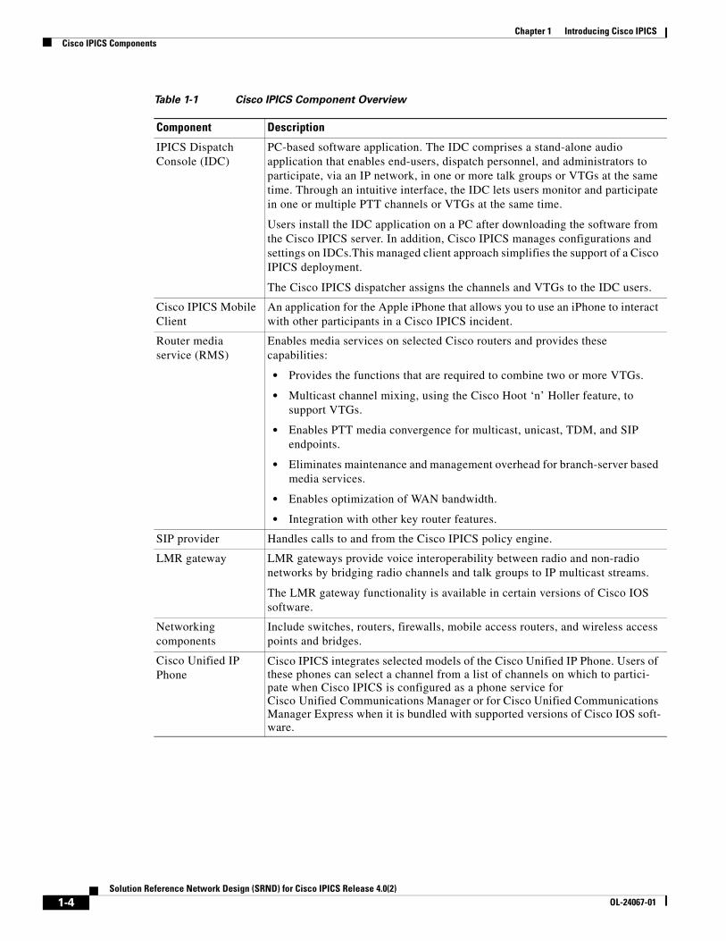
Table 1-1 Cisco IPICS Component Overview
Component Description
Cisco IPICS server Provides the core functionality of the Cisco IPICS system. The Cisco IPICS server software runs on the Cisco Linux operating system (based on Red Hat Linux) on selected Cisco Media Convergence Server (MCS) platforms and Cisco Multiservices Platforms (MSP) and performs these functions:
• Hosts the Cisco IPICS Administration Console, which is an incident management framework administration GUI that enables dynamic resource management for users, channels, and virtual talk groups (VTGs).
• Provides Cisco IPICS authentication and security services
• Stores configuration and operational data
• Enables integration with various media resources, such as RMS components, IDCs, Cisco Unified IP Phones, Cisco Unified Communications Manager, and Cisco IOS SIP gateways
1-3Solution Reference Network Design (SRND) for Cisco IPICS Release 4.0(2)
OL-24067-01
Chapter 1 Introducing Cisco IPICSCisco IPICS Components
IPICS Dispatch Console (IDC)
PC-based software application. The IDC comprises a stand-alone audio application that enables end-users, dispatch personnel, and administrators to participate, via an IP network, in one or more talk groups or VTGs at the same time. Through an intuitive interface, the IDC lets users monitor and participate in one or multiple PTT channels or VTGs at the same time.
Users install the IDC application on a PC after downloading the software from the Cisco IPICS server. In addition, Cisco IPICS manages configurations and settings on IDCs.This managed client approach simplifies the support of a Cisco IPICS deployment.
The Cisco IPICS dispatcher assigns the channels and VTGs to the IDC users.
Cisco IPICS Mobile Client
An application for the Apple iPhone that allows you to use an iPhone to interact with other participants in a Cisco IPICS incident.
Router media service (RMS)
Enables media services on selected Cisco routers and provides these capabilities:
• Provides the functions that are required to combine two or more VTGs.
• Multicast channel mixing, using the Cisco Hoot ‘n’ Holler feature, to support VTGs.
• Enables PTT media convergence for multicast, unicast, TDM, and SIP endpoints.
• Eliminates maintenance and management overhead for branch-server based media services.
• Enables optimization of WAN bandwidth.
• Integration with other key router features.
SIP provider Handles calls to and from the Cisco IPICS policy engine.
LMR gateway LMR gateways provide voice interoperability between radio and non-radio networks by bridging radio channels and talk groups to IP multicast streams.
The LMR gateway functionality is available in certain versions of Cisco IOS software.
Networking components
Include switches, routers, firewalls, mobile access routers, and wireless access points and bridges.
Cisco Unified IP Phone
Cisco IPICS integrates selected models of the Cisco Unified IP Phone. Users of these phones can select a channel from a list of channels on which to partici-pate when Cisco IPICS is configured as a phone service for Cisco Unified Communications Manager or for Cisco Unified Communications Manager Express when it is bundled with supported versions of Cisco IOS soft-ware.
Table 1-1 Cisco IPICS Component Overview
Component Description
1-4Solution Reference Network Design (SRND) for Cisco IPICS Release 4.0(2)
OL-24067-01
Solution Reference NeOL-24067-01
C H A P T E R 2
Cisco IPICS Component ConsiderationsThis chapter provides information about various components and features that can be part of a Cisco IPICS solution. This information will help you to understand how these items interoperate in a Cisco IPICS deployment.
This chapter includes these topics:
• Router Media Service, page 2-1
• Integrating Cisco IPICS with SIP Providers, page 2-29
• IDC Dialer Configuration and Integration with Unified Communications Platform, page 2-35
• Cisco IPICS Mobile Client for Apple iPhone, page 2-38
• Cisco Unified IP Phones, page 2-47
• Text to Speech, page 2-48
• Video Considerations, page 2-53
• Notification, page 2-55
Router Media ServiceThe Cisco IPICS solution uses one or more of the supported Cisco IOS routers to provide the router media service (RMS) functionality.
The following sections provide additional information about the RMS:
• RMS Overview, page 2-2
• RMS Components for Locations, page 2-2
• When is an RMS Required?, page 2-7
• Allocation of RMS DS0 Resources, page 2-9
• Media Resource Allocation for the Dial Engine, page 2-10
• Virtual Talk Groups, page 2-11
• Remote IDC Users, page 2-24
For detailed information about configuring an RMS for Cisco IPICS, refer to the “Configuring the Cisco IPICS RMS Component” appendix in Cisco IPICS Server Administration Guide, Release 4.02.
For a list of Cisco IOS releases that Cisco IPICS supports for use as an RMS, refer to Cisco IPICS Compatibility Matrix. Each supported Cisco IOS release includes the Cisco Hoot ‘n’ Holler feature.
2-1twork Design (SRND) for Cisco IPICS Release 4.0(2)
Chapter 2 Cisco IPICS Component ConsiderationsRouter Media Service
RMS OverviewThe primary role of the RMS is to provide media stream mixing by looping back DS0 resources. When an RMS is installed, it must have one or more pairs of T1 or E1 interfaces that are connected back to back with a T1 loopback cable. These loopback interface pairs are manually configured in the RMS by adding the DS0-Group to timeslot mapping. (For related information, refer to the “Configuring the Cisco IPICS RMS Component” appendix in Cisco IPICS Server Administration Guide, Release 4.0(2).) When you use the Cisco IPICS Administration Console to add an RMS, the loopback pairs becomes available for assignment. A properly configured RMS will make a list of DS0 loopback channels available for dynamic allocation by the Cisco IPICS server.
The RMS can be installed as a stand-alone component (RMS router) or as an additional feature that is installed in the LMR gateway.
The Cisco IPICS server dynamically allocates a DS0 loopback pair (two DS0 channels) in the following scenarios:
• Successful Authentication of an IPICS Dispatch Console (IDC) from the remote location—When a remote IDC connection is started, the IDC authenticates to the Cisco IPICS server. The Cisco IPICS server then configures the RMS to allocate a DS0 loopback pair for each channel or virtual talk group (VTG) that is assigned to the IDC user. The IDC retrieves configuration information that contains the IP address of the RMS and the channel details with the Plain Old Telephone Service (POTS) dial-peer information that the Cisco IPICS server configured in the RMS. Then, when the IDC user activates a channel or VTG, the IDC places a SIP call to the POTS dial-peer in the RMS and connects to that channel or VTG.
• Activation or change of a VTG—When a Cisco IPICS dispatcher performs VTG operations that affects an RMS, the Cisco IPICS server updates the RMS as needed. For example, if a VTG with two channels is activated, the Cisco IPICS server configures two DS0 loopback pairs, one for each channel. This configuration will include assigning each side of corresponding voice-port for the allocated DS0 loopback pair to a connection trunk.
• A dial-in user joins a channel or VTG—A single DS0 loopback pair is added per channel or VTG regardless of the number of dial-in users who join the channel or VTG.
• A mobile client user log in to the Cisco IPICS server—A single DS0 loopback pair is used for each incident.
RMS Components for LocationsAn RMS supports one Cisco IPICS location, which is defined as a multicast domain. If a Cisco IPICS deployment requires RMS functionality in more than one location, there must be an RMS configured for each of those locations. The multicast address pool contains a list of multicast addresses and their respective port assignments. The addresses in the pool are allocated, as needed, by the Cisco IPICS server when it configures an RMS. The Cisco IPICS server keeps track of the in-use and the available addresses.
The multicast address pool is a global resource that is shared across all RMS components that are configured in that Cisco IPICS server. Therefore the network configuration must be able to support all of the configured addresses in all of the configured RMS components. The IPICS server attempts to load balance across all RMS components that are in the same location. For this reason, it is important that you configure each RMS according to the instructions that are documented in the “Configuring the Cisco IPICS RMS Component” appendix in Cisco IPICS Server Administration Guide, Release 4.0(2) if you have more than one RMS configured in the server.
The following information applies to locations:
2-2Solution Reference Network Design (SRND) for Cisco IPICS Release 4.0(2)
OL-24067-01
Chapter 2 Cisco IPICS Component ConsiderationsRouter Media Service
• A channel is associated to a location.
• A VTG is a global resource that can span multiple locations.
• A user may be assigned channels from multiple locations, but when the user authenticates, the user must select the desired location. Channel resources are allocated based on the selected location.
Multiple Location Example
As an example of how Cisco IPICS and RMS components function in multiple locations, consider the following scenario:
• User A is in the Site 1 location and is assigned the Emergency VTG
• User B is in the Site 2 location and is assigned the Emergency VTG
• Channel EMT1 is in the Site 1 location
• Channel EMT2 is in the Site 2 location
• The Emergency VTG is assigned both channel EMT1 and channel EMT2
• RMS 1 is in the Site 1 location
• RMS 2 is in the Site 2 location
When the Cisco IPICS dispatcher activates the Emergency VTG, the Cisco IPICS server assigns to the VTG a multicast address from the multicast address pool. It also configures DS0 loopback resources in RMS 1 and RMS 2.
In this way, users in both locations can communicate by using the VTG. Be aware that this scenario requires that there must be multicast connectivity between both locations. If both locations are isolated multicast domains, there must be a way to route the multicast traffic between locations. For related information, see the “Multiple Site Model” section on page 7-2.
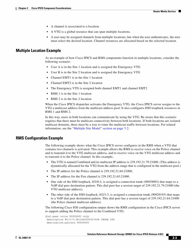
RMS Configuration Example
The following example shows what the Cisco IPICS server configures in the RMS when a VTG that contains two channels is activated. This example allows the RMS to receive voice on the Police channel and to transmit it to the VTG multicast address, and to receive voice on the VTG multicast address and to transmit it to the Police channel. In this example,
• The VTG is named Combined and its multicast IP address is 239.192.21.79:21000. (This address is dynamically allocated for the VTG from the address range that is configured in the multicast pool.)
• The IP address for the Police channel is 239.192.21.64:21000.
• The IP address for the Fire channel is 239.192.21.65:21000.
• One side of the DS0 loopback, 0/2/0:3, is assigned a connection trunk (90929093) that maps to a VoIP dial peer destination pattern. This dial peer has a session target of 239.192.21.79:21000 (the VTG multicast address).
• The other side of the DS0 loopback, 0/2/1:3, is assigned a connection trunk (90929193) that maps to a VoIP dial peer destination pattern. This dial peer has a session target of 239.192.21.64:21000 (the Police channel multicast address).
The following Cisco IOS configuration output shows the RMS configuration in the Cisco IPICS server to support adding the Police channel to the Combined VTG:
dial-peer voice 90929093 voip description #0/2/0:3#1164200525742# INUSE 284 destination-pattern 90929093
2-3Solution Reference Network Design (SRND) for Cisco IPICS Release 4.0(2)
OL-24067-01
Chapter 2 Cisco IPICS Component ConsiderationsRouter Media Service
voice-class permanent 1 session protocol multicast session target ipv4:239.192.21.79:21000 codec g711ulaw no vad
voice-port 0/2/0:3 voice-class permanent 1 auto-cut-through lmr m-lead audio-gate-in lmr e-lead voice no echo-cancel enable playout-delay maximum 100 no comfort-noise timeouts call-disconnect 3 timeouts teardown lmr infinity timing hookflash-in 0 timing hangover 80 connection trunk 90929093 description #0/2/0:3#1164200525742# INUSE 284
voice-port 0/2/1:3 voice-class permanent 1 auto-cut-through lmr m-lead audio-gate-in lmr e-lead voice no echo-cancel enable playout-delay maximum 100 no comfort-noise timeouts call-disconnect 3 timeouts teardown lmr infinity timing hookflash-in 0 timing hangover 80 connection trunk 90929193 description #0/2/1:3#1164200525742# INUSE 284
dial-peer voice 90929193 voip description #0/2/1:3#1164200525742# INUSE 284 destination-pattern 90929193 voice-class permanent 1 session protocol multicast session target ipv4:239.192.21.64:21000 codec g711ulaw
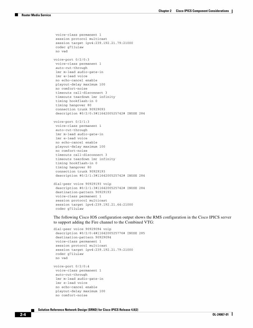
The following Cisco IOS configuration output shows the RMS configuration in the Cisco IPICS server to support adding the Fire channel to the Combined VTG:
dial-peer voice 90929094 voip description #0/2/0:4#1164200525776# INUSE 285 destination-pattern 90929094 voice-class permanent 1 session protocol multicast session target ipv4:239.192.21.79:21000 codec g711ulaw no vad
voice-port 0/2/0:4 voice-class permanent 1 auto-cut-through lmr m-lead audio-gate-in lmr e-lead voice no echo-cancel enable playout-delay maximum 100 no comfort-noise
2-4Solution Reference Network Design (SRND) for Cisco IPICS Release 4.0(2)
OL-24067-01
Chapter 2 Cisco IPICS Component ConsiderationsRouter Media Service
timeouts call-disconnect 3 timeouts teardown lmr infinity timing hookflash-in 0 timing hangover 80 connection trunk 90929094 description #0/2/0:4#1164200525776# INUSE 285
voice-port 0/2/1:4 voice-class permanent 1 auto-cut-through lmr m-lead audio-gate-in lmr e-lead voice no echo-cancel enable playout-delay maximum 100 no comfort-noise timeouts call-disconnect 3 timeouts teardown lmr infinity timing hookflash-in 0 timing hangover 80 connection trunk 90929194 description #0/2/1:4#1164200525776# INUSE 285
dial-peer voice 90929194 voip description #0/2/1:4#1164200525776# INUSE 285 destination-pattern 90929194 voice-class permanent 1 session protocol multicast session target ipv4:239.192.21.65:21000 codec g711ulaw no vad
The following Cisco IOS configuration outputs shows the RMS configuration in the Cisco IPICS server to support an IDC user who is assigned both the Police and Fire channels connecting by using the remote location. This configuration allows the IDC to communicate with RMS by using a unicast connection. The RMS forwards the unicast stream, which is received from the IDC, through a DS0 loopback to the multicast address. Packets that the RMS receives for a multicast address are forwarded through a DS0 loopback to the receiving IDC device as a unicast stream.
This Cisco IOS configuration output pertains to the Police channel:
dial-peer voice 909290914 voip description #0/2/0:14#1164659525783# INUSE 295 destination-pattern 909290914 voice-class permanent 1 session protocol multicast session target ipv4:239.192.21.64:21000 codec g711ulaw no vad
voice-port 0/2/0:14 voice-class permanent 1 auto-cut-through lmr m-lead audio-gate-in lmr e-lead voice no echo-cancel enable playout-delay maximum 100 no comfort-noise timeouts call-disconnect 3 timeouts teardown lmr infinity timing hookflash-in 0 timing hangover 80 connection trunk 909290914
2-5Solution Reference Network Design (SRND) for Cisco IPICS Release 4.0(2)
OL-24067-01

Chapter 2 Cisco IPICS Component ConsiderationsRouter Media Service
voice-port 0/2/1:14 voice-class permanent 1 auto-cut-through lmr m-lead audio-gate-in lmr e-lead voice no echo-cancel enable playout-delay maximum 100 no comfort-noise timeouts call-disconnect 3 timeouts teardown lmr infinity timing hookflash-in 0 timing hangover 80 description #0/2/1:14#1164659525783# INUSE 295
dial-peer voice 909291914 pots description #0/2/1:14#1164659525783# INUSE 295 destination-pattern 1990000275909291914 port 0/2/1:14
This Cisco IOS configuration output pertains to the Fire channel:
dial-peer voice 909290915 voip description #0/2/0:15#1164659525833# INUSE 296 destination-pattern 909290915 voice-class permanent 1 session protocol multicast session target ipv4:239.192.21.65:21000 codec g711ulaw no vad
voice-port 0/2/0:15 voice-class permanent 1 auto-cut-through lmr m-lead audio-gate-in lmr e-lead voice no echo-cancel enable playout-delay maximum 100 no comfort-noise timeouts call-disconnect 3 timeouts teardown lmr infinity timing hookflash-in 0 timing hangover 80 connection trunk 909290915 description #0/2/0:15#1164659525833# INUSE 296
voice-port 0/2/1:15 voice-class permanent 1 auto-cut-through lmr m-lead audio-gate-in lmr e-lead voice no echo-cancel enable playout-delay maximum 100 no comfort-noise timeouts call-disconnect 3 timeouts teardown lmr infinity timing hookflash-in 0 timing hangover 80 description #0/2/1:15#1164659525833# INUSE 296
dial-peer voice 909291915 pots description #0/2/1:15#1164659525833# INUSE 296 destination-pattern 1990000275909291915 port 0/2/1:15
2-6Solution Reference Network Design (SRND) for Cisco IPICS Release 4.0(2)
OL-24067-01
Chapter 2 Cisco IPICS Component ConsiderationsRouter Media Service
When is an RMS Required?Cisco IPICS requires an RMS to establish connectivity between unicast and multicast endpoints (such as remote IDC to channel, mobile client to Cisco IPICS server, remote IDC to VTG, and dial-in user to channel or VTG), and to establish connectivity between multicast endpoints that are on different channels (such as channel to VTG, and VTG to VTG).
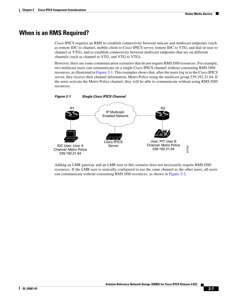
However, there are some communication scenarios that do not require RMS DS0 resources. For example, two multicast users can communicate on a single Cisco IPICS channel without consuming RMS DS0 resources, as illustrated in Figure 2-1. This examples shows that, after the users log in to the Cisco IPICS server, they receive their channel information, Metro Police using the multicast group 239.192.21.64. If the users activate the Metro Police channel, they will be able to communicate without using RMS DS0 resources.
Figure 2-1 Single Cisco IPICS Channel
Adding an LMR gateway and an LMR user to this scenario does not necessarily require RMS DS0 resources. If the LMR user is statically configured to use the same channel as the other users, all users can communicate without consuming RMS DS0 resources, as shown in Figure 2-2.
IP
IP Multicast-Enabled Network
R2R1
2375
30
User: PIT User BChannel: Metro Police
239.192.21.64IDC User: User A
Channel: Metro Police239.192.21.64
Cisco IPICSServer
2-7Solution Reference Network Design (SRND) for Cisco IPICS Release 4.0(2)
OL-24067-01

Chapter 2 Cisco IPICS Component ConsiderationsRouter Media Service
Figure 2-2 Single Cisco IPICS Channel with LMR Gateway
As another example, a scenario with two sets of users on two separate channels does not consume RMS DS0 resources if communication between the channels is not required. In the scenario shown in Figure 2-3, Metro Police users can communicate with each other, and Metro Fire users can communicate with each other, without consuming RMS DS0 resources. In this scenario, no RMS resources are required because there is no communication between Metro Police and Metro Fire users.
Figure 2-3 Several Cisco IPICS Channels
IPIP Multicast-
Enabled Network
R2
R3
R1
2375
31
User: PIT User BChannel: Metro Police
239.192.21.64
IDC User: User AChannel: Metro Police
239.192.21.64
Cisco IPICSServer
E&MLMR 1239.192.21.64Metro Police
IP
IP Multicast-Enabled Network
R2
R3
R1
2375
32
User: PIT User BChannel: Metro Police
239.192.21.64
User: PIT User DChannel: Metro Fire239.192.21.64
IDC User: User AChannel: Metro Police
239.192.21.64
IDC User: User CChannel: Metro Fire
239.192.21.65
Cisco IPICSServer
E&MLMR 1239.192.21.64Metro Police
E&MLMR 2239.192.21.65
Metro Fire
IP
Group 2 Metro FireChannel 239.192.21.65IDC 3, IDC 4, LMR/Hootie 2
Group 1 Metro PoliceChannel 239.192.21.64IDC 1, IDC 2, LMR/Hootie 1
2-8Solution Reference Network Design (SRND) for Cisco IPICS Release 4.0(2)
OL-24067-01
Chapter 2 Cisco IPICS Component ConsiderationsRouter Media Service
Allocation of RMS DS0 ResourcesYou can create a VTG that allows only specific users to communicate by using that VTG. In this case, the VTG does not include channels and it does not use RMS DS0 resources (unless there are IDC users who connect by using the Remote location), but it does use a multicast address from the multicast pool.
If a VTG needs to include LMR endpoints, each of the LMR channels must be added to the VTG, in addition to the channels for the IDC or phone users. If a user is not added to the VTG but has a channel that is in the VTG, the user will still be able to send to and receive from the VTG.
After an IDC successfully authenticates by using the Remote location, the RMS allocates a DS0 pair to each channel or VTG that is assigned to that authenticated IDC user. (See the “Remote IDC Users” section on page 2-24 for related information.)
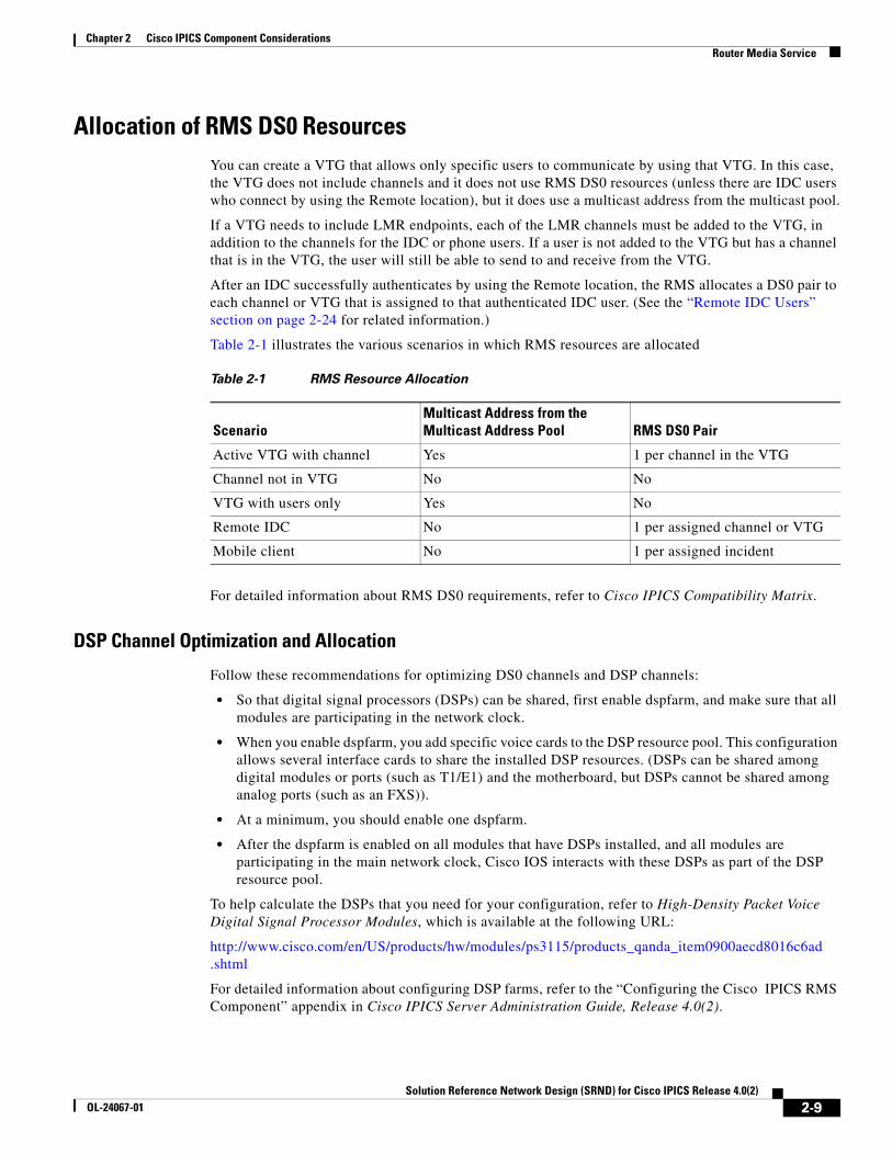
Table 2-1 illustrates the various scenarios in which RMS resources are allocated
For detailed information about RMS DS0 requirements, refer to Cisco IPICS Compatibility Matrix.
DSP Channel Optimization and Allocation
Follow these recommendations for optimizing DS0 channels and DSP channels:
• So that digital signal processors (DSPs) can be shared, first enable dspfarm, and make sure that all modules are participating in the network clock.
• When you enable dspfarm, you add specific voice cards to the DSP resource pool. This configuration allows several interface cards to share the installed DSP resources. (DSPs can be shared among digital modules or ports (such as T1/E1) and the motherboard, but DSPs cannot be shared among analog ports (such as an FXS)).
• At a minimum, you should enable one dspfarm.
• After the dspfarm is enabled on all modules that have DSPs installed, and all modules are participating in the main network clock, Cisco IOS interacts with these DSPs as part of the DSP resource pool.
To help calculate the DSPs that you need for your configuration, refer to High-Density Packet Voice Digital Signal Processor Modules, which is available at the following URL:
http://www.cisco.com/en/US/products/hw/modules/ps3115/products_qanda_item0900aecd8016c6ad .shtml
For detailed information about configuring DSP farms, refer to the “Configuring the Cisco IPICS RMS Component” appendix in Cisco IPICS Server Administration Guide, Release 4.0(2).
Table 2-1 RMS Resource Allocation
ScenarioMulticast Address from the Multicast Address Pool RMS DS0 Pair
Active VTG with channel Yes 1 per channel in the VTG
Channel not in VTG No No
VTG with users only Yes No
Remote IDC No 1 per assigned channel or VTG
Mobile client No 1 per assigned incident
2-9Solution Reference Network Design (SRND) for Cisco IPICS Release 4.0(2)
OL-24067-01
Chapter 2 Cisco IPICS Component ConsiderationsRouter Media Service
Examples of Hardware Configuration and Supported Voice Streams
This section provides examples of various hardware configurations and the number of voice streams that can be supported for use with Cisco IPICS.
When you use the Cisco 2811 with one T1/E1 Multiflex Trunk Voice/WAN Interface (VWIC-2MFT-T1/E1) card installed on the motherboard, up to 24 pairs of DS0 channels are available for use if the card is configured for T1 mode. If the card is configured for E1 mode, up to 30 DS0 channels are available. The number of supported voice streams varies based on the configuration that you use. For example, with one 64-channel high-density Packet Voice/Fax DSP Module (PVDM2-64) installed, support is provided for up to 32 pairs of voice streams when using the G.711 u-law codec. If you use the G.729 u-law codec, the PVDM2-64 provides support for 16 pairs of voice streams. In this situation, one PVDM2-64 does not support full utilization of all pairs of DS0 channels on a T1 line.
The following options are also available for use with the Cisco 2811:
• Three VWIC-2MFT-T1/E1 interface cards installed on the motherboard with two PVDM2-64 modules, for a total of 128 channels.
• One T1/E1 High Density Digital Voice Network Module (NM-HDV2-2T1/E1) that is fully populated with four PVDM2-64 modules, for a total of 256 channels, and two VWIC-MFT-T1/E1 interface cards.
Note Before you order router hardware for your Cisco IPICS deployment, Cisco recommends that you determine the number of DS0 channels that you need and your DSP requirements, based on the interface modules and codec configurations that you use, to ensure full support for your deployment. For example, if you configure the T1/E1 cards for E1 connectivity, support is provided for 150 pairs of DS0 channels and 384 DSP resources. Based on the codec that you use, this DSP resource can provide support for 96 G.729 voice streams or 150 G.711 voice streams.
For more information about Cisco interfaces and modules, go to the following URL:
http://www.cisco.com/en/US/products/hw/modules/prod_module_category_home.html
Media Resource Allocation for the Dial EngineWhen a user dials in to the Cisco IPICS dial engine, the user accesses the system through a SIP-based (unicast) connection and obtains a media connection to the Cisco IPICS server. When the user joins a channel or VTG, Cisco IPICS configures a T1 loopback (DS0) resource on the RMS to enable a multicast connection from the Cisco IPICS server to the allocated loopback. This loopback configuration facilitates a multicast connection between the Cisco IPICS server and the selected channel or VTG on the RMS.
This multicast connection is made one time for a channel or VTG, regardless of the number of dial-in users who select the channel or VTG. When the last dial-in user disconnects from the channel or VTG, the resource is released in the RMS and becomes available for use.
When a dial-in user makes a unicast media connection to the media driver on the Cisco IPICS server, the policy engine sends and receives multicast streams as follows:
1. After the dial-in user successfully authenticates and selects a resource, Cisco IPICS allocates a DS0 loopback in the RMS for the user and allocates a multicast address from the multicast pool. Cisco IPICS then performs an Internet Group Management Protocol (IGMP) join operation on the multicast address so that when additional dial-in users select the same resource, the Cisco IPICS server can continue to use same the multicast address.
2-10Solution Reference Network Design (SRND) for Cisco IPICS Release 4.0(2)
OL-24067-01
Chapter 2 Cisco IPICS Component ConsiderationsRouter Media Service
2. When the dial-in user presses 1 on a telephone and begins to talk, Cisco IPICS transmits the audio to the multicast address of the selected resources.
3. When the RMS receives the multicast packets, it forwards the packets to the multicast address that has been allocated from the multicast pool. Cisco IPICS receives that multicast audio stream and forwards it as a unicast stream to all dial-in users who have selected that resource.
Virtual Talk GroupsA virtual talk group (VTG) enables participants on various channels to communicate by using a single multicast address. A VTG contains, in a temporary channel, any combination of the following members:
• Channels
• Channel groups
• Users
• User groups
• Other VTGs
A Cisco IPICS administrator creates Cisco IPICS channels and assigns a multicast address to each one. A Cisco IPICS dispatcher creates VTGs as needed. When a dispatcher creates a VTG, the Cisco IPICS server automatically allocates to the VTG an available address from the multicast pool. So while VTGs are dynamically assigned addresses from the multicast pool, channels are configured as static addresses that are outside the range of the addresses that are used by VTGs.
A VTG allows communication between endpoints that are assigned different multicast addresses, such as two endpoints that have activated different channels. When a VTG is enabled to facilitate communications between two or more endpoints with different multicast addresses, an RMS must bridge, or mix, the multicast streams of each channel. In this VTG scenario, the Cisco IPICS sever allocates a loopback voice port for each channel in the VTG.
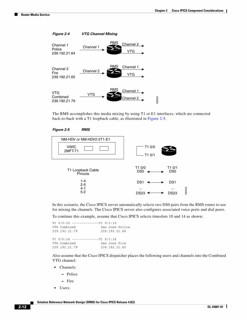
For example, assume that a dispatcher creates a VTG named Combined and that this VTG includes the Police channel and Fire channel as members. Also assume that each LMR voice port is statically configured with a multicast address, so that LMR police users always send to the Police channel, and LMR fire users always send to the Fire channel. To provide communication between the Police channel and the Fire channel, an RMS must bridge the multicast streams from these channels.
In this example, when a user talks on the Police channel (channel 1), the RMS router must bridge that multicast stream to the Fire channel (channel 2) and to the VTG channel. The RMS must perform similar operations when a user talks on channel 2 or on the VTG channel. See Figure 2-4.
2-11Solution Reference Network Design (SRND) for Cisco IPICS Release 4.0(2)
OL-24067-01
Chapter 2 Cisco IPICS Component ConsiderationsRouter Media Service
Figure 2-4 VTG Channel Mixing
The RMS accomplishes this media mixing by using T1 or E1 interfaces, which are connected back-to-back with a T1 loopback cable, as illustrated in Figure 2-5.
Figure 2-5 RMS
In this scenario, the Cisco IPICS server automatically selects two DS0 pairs from the RMS router to use for mixing the channels. The Cisco IPICS server also configures associated voice ports and dial peers.
To continue this example, assume that Cisco IPICS selects timeslots 10 and 14 as shown:
T1 0/0:10 --------------T1 0/1:10 VTG Combined San Jose Police239.192.21.79 239.192.21.64
T1 0/0:14 --------------T1 0/1:14 VTG Combined San Jose Fire239.192.21.79 239.192.21.65
Also assume that the Cisco IPICS dispatcher places the following users and channels into the Combined VTG channel:
• Channels:
– Police
– Fire
• Users:
Channel 2
Channel 2
VTG
VTG
Channel 1
Channel 1
Channel 1
Channel 2
VTG
RMS
RMS
RMS
Channel 1Police239.192.21.64
Channel 2Fire239.192.21.65
VTGCombined239.192.21.79
1805
52
T1 0/0DS0
DS1
DS23
T1 0/1DS0
DS1
DS23... ...
T1 Loopback CablePinouts
1-42-54-15-2
T1 0/0
T1 0/1
NM-HDV or NM-HDV2-2T1-E1
VWIC2MFT-T1
1805
53
2-12Solution Reference Network Design (SRND) for Cisco IPICS Release 4.0(2)
OL-24067-01
Chapter 2 Cisco IPICS Component ConsiderationsRouter Media Service
– User 1
– User 2
– User 3
– User 4
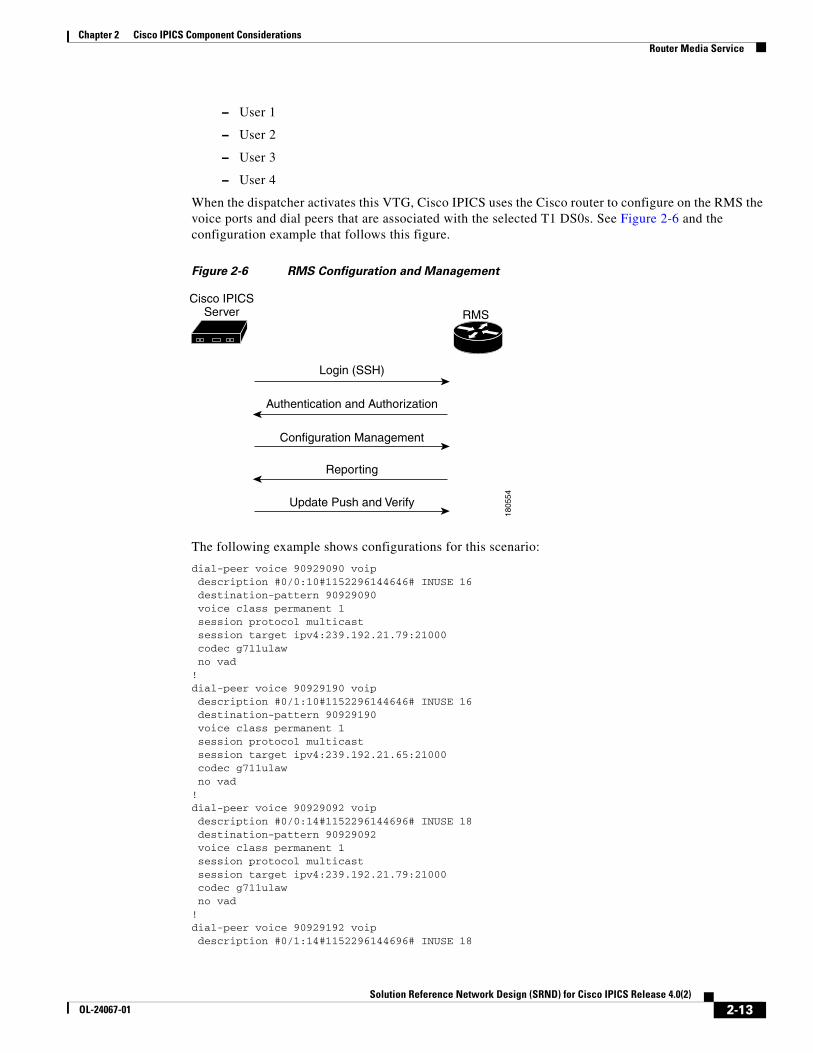
When the dispatcher activates this VTG, Cisco IPICS uses the Cisco router to configure on the RMS the voice ports and dial peers that are associated with the selected T1 DS0s. See Figure 2-6 and the configuration example that follows this figure.
Figure 2-6 RMS Configuration and Management
The following example shows configurations for this scenario:
dial-peer voice 90929090 voip description #0/0:10#1152296144646# INUSE 16 destination-pattern 90929090 voice class permanent 1 session protocol multicast session target ipv4:239.192.21.79:21000 codec g711ulaw no vad! dial-peer voice 90929190 voip description #0/1:10#1152296144646# INUSE 16 destination-pattern 90929190 voice class permanent 1 session protocol multicast session target ipv4:239.192.21.65:21000 codec g711ulaw no vad!dial-peer voice 90929092 voip description #0/0:14#1152296144696# INUSE 18 destination-pattern 90929092 voice class permanent 1 session protocol multicast session target ipv4:239.192.21.79:21000 codec g711ulaw no vad!dial-peer voice 90929192 voip description #0/1:14#1152296144696# INUSE 18
RMSCisco IPICS
Server
1805
54
Login (SSH)
Authentication and Authorization
Configuration Management
Reporting
Update Push and Verify
2-13Solution Reference Network Design (SRND) for Cisco IPICS Release 4.0(2)
OL-24067-01

Chapter 2 Cisco IPICS Component ConsiderationsRouter Media Service
destination-pattern 90929192 voice class permanent 1 session protocol multicast session target ipv4:239.192.21.64:21000 codec g711ulaw no vad !voice-port 0/0:10 voice class permanent 1 auto-cut-through lmr m-lead audio-gate-in lmr e-lead voice no echo-cancel enable playout-delay maximum 100 no comfort-noise timeouts call-disconnect 3 timing hookflash-in 0 timing hangover 80 connection trunk 90929090 description #0/0:10#1152296144646# INUSE 16!voice-port 0/0:14 voice class permanent 1 auto-cut-through lmr m-lead audio-gate-in lmr e-lead voice no echo-cancel enable playout-delay maximum 100 no comfort-noise timeouts call-disconnect 3 timeouts teardown lmr infinity timing hookflash-in 0 timing hangover 80 connection trunk 90929092 description #0/0:14#1152296144696# INUSE 18 !voice-port 0/1:10 voice class permanent 1 auto-cut-through lmr m-lead audio-gate-in lmr e-lead voice no echo-cancel enable playout-delay maximum 100 no comfort-noise timeouts call-disconnect 3 timing hookflash-in 0 timing hangover 80 connection trunk 90929190 description #0/1:10#1152296144646# INUSE 16 !voice-port 0/0:14 voice class permanent 1 auto-cut-through lmr m-lead audio-gate-in lmr e-lead voice no echo-cancel enable playout-delay maximum 100 no comfort-noise timeouts call-disconnect 3 timeouts teardown lmr infinity timing hookflash-in 0 timing hangover 80 connection trunk 90929192 description #0/1:14#1152296144696# INUSE 18
2-14Solution Reference Network Design (SRND) for Cisco IPICS Release 4.0(2)
OL-24067-01
Chapter 2 Cisco IPICS Component ConsiderationsRouter Media Service
Using the Cisco Hoot ‘n’ Holler Feature to Mix Channels in the RMS
The RMS uses the Cisco Hoot ‘n’ Holler feature to mix channels. Cisco Hoot 'n' Holler is a communications system in which the three most recent talkers are mixed into one multicast output stream. Also known as hootie, these networks provide “always on” multi-user conferences without requiring that users dial in to a conference.
For additional information about Cisco Hoot ‘n’ Holler, refer to the documentation at the following URLs:
• http://www.cisco.com/en/US/products/ps6552/products_ios_technology_home.html
• http://www.cisco.com/en/US/tech/tk828/tsd_technology_support_protocol_home.html
• Multicast Hoot ‘n’ Holler White Paper: http://www.cisco.com/warp/public/cc/so/neso/vvda/hthllr/hhoip_wp.pdf
A virtual interface (VIF) is used to associate an IP address with the voice ports on the RMS. In the example shown in Figure 2-4 on page 2-12, the RMS joins channels Police (239.192.21.64), Fire (239.192.21.65), and the Combined VTG (239.192.21.79).
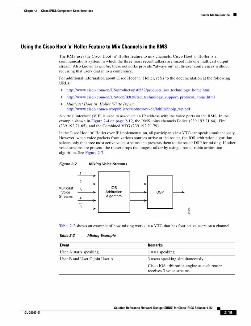
In the Cisco Hoot ‘n’ Holler over IP implementation, all participants in a VTG can speak simultaneously, However, when voice packets from various sources arrive at the router, the IOS arbitration algorithm selects only the three most active voice streams and presents them to the router DSP for mixing. If other voice streams are present, the router drops the longest talker by using a round-robin arbitration algorithm. See Figure 2-7.
Figure 2-7 Mixing Voice Streams
Table 2-2 shows an example of how mixing works in a VTG that has four active users on a channel.
1
2
3
4...n
IOSArbitrationAlgorithm
DSPMulticast
VoiceStreams
1805
55
Table 2-2 Mixing Example
Event Remarks
User A starts speaking. 1 user speaking.
User B and User C join User A. 3 users speaking simultaneously.
Cisco IOS arbitration engine at each router receives 3 voice streams.
2-15Solution Reference Network Design (SRND) for Cisco IPICS Release 4.0(2)
OL-24067-01
Chapter 2 Cisco IPICS Component ConsiderationsRouter Media Service
Cisco IPICS Endpoint Scenarios
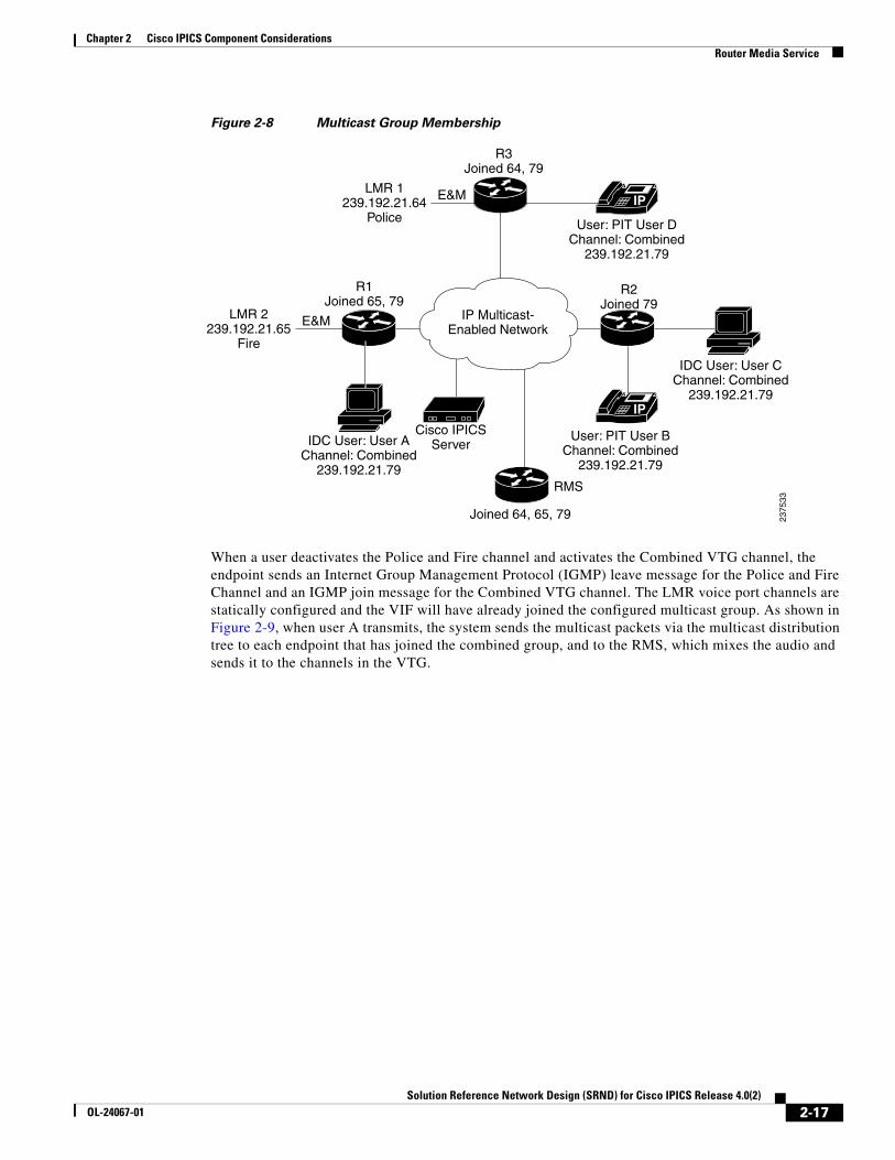
When a Cisco IPICS dispatcher activates the Combined VTG (as shown in Figure 2-3 on page 2-8), Cisco IPICS configures the RMS router to mix the Police, Fire, and Combined VTG channels. Users who have been added to the VTG will see the new Combined VTG channel on their IDCs or Cisco Unified IP Phones. LMR endpoints do not have associated users. An LMR channel is statically configured, so an LMR user can send and receive only from the Cisco IPICS channel that is configured with the same multicast address as the LMR channel. An LMR user can communicate only with endpoints that are not using the same channel if the channel of the LMR user is in a VTG with other channels or users.
Figure 2-8 illustrates a scenario in which four users have deactivated their police or fire channels and have activated the Combined VTG channel.
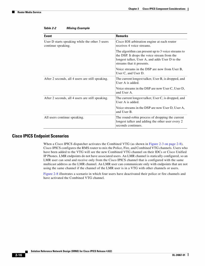
User D starts speaking while the other 3 users continue speaking.
Cisco IOS arbitration engine at each router receives 4 voice streams.
The algorithm can present up to 3 voice streams to the DSP. It drops the voice stream from the longest talker, User A, and adds User D to the streams that it presents.
Voice streams in the DSP are now from User B, User C, and User D.
After 2 seconds, all 4 users are still speaking. The current longest talker, User B, is dropped, and User A is added.
Voice streams in the DSP are now User C, User D, and User A.
After 2 seconds, all 4 users are still speaking. The current longest talker, User C, is dropped, and User A is added.
Voice streams in the DSP are now User D, User A, and User B.
All users continue speaking. The round-robin process of dropping the current longest talker and adding the other user every 2 seconds continues.
Table 2-2 Mixing Example
Event Remarks
2-16Solution Reference Network Design (SRND) for Cisco IPICS Release 4.0(2)
OL-24067-01
Chapter 2 Cisco IPICS Component ConsiderationsRouter Media Service
Figure 2-8 Multicast Group Membership
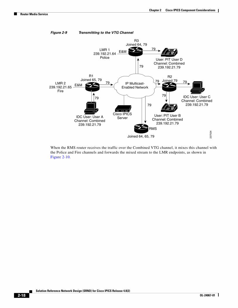
When a user deactivates the Police and Fire channel and activates the Combined VTG channel, the endpoint sends an Internet Group Management Protocol (IGMP) leave message for the Police and Fire Channel and an IGMP join message for the Combined VTG channel. The LMR voice port channels are statically configured and the VIF will have already joined the configured multicast group. As shown in Figure 2-9, when user A transmits, the system sends the multicast packets via the multicast distribution tree to each endpoint that has joined the combined group, and to the RMS, which mixes the audio and sends it to the channels in the VTG.
IP
IP
IP Multicast-Enabled Network
R2Joined 79
R1Joined 65, 79
Joined 64, 65, 79
R3Joined 64, 79
2375
33
User: PIT User BChannel: Combined
239.192.21.79
IDC User: User AChannel: Combined
239.192.21.79
IDC User: User CChannel: Combined
239.192.21.79
User: PIT User DChannel: Combined
239.192.21.79
Cisco IPICSServer
E&MLMR 1239.192.21.64
Police
E&MLMR 2239.192.21.65
Fire
RMS
2-17Solution Reference Network Design (SRND) for Cisco IPICS Release 4.0(2)
OL-24067-01
Chapter 2 Cisco IPICS Component ConsiderationsRouter Media Service
Figure 2-9 Transmitting to the VTG Channel
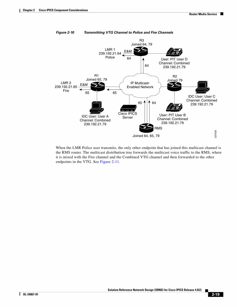
When the RMS router receives the traffic over the Combined VTG channel, it mixes this channel with the Police and Fire channels and forwards the mixed stream to the LMR endpoints, as shown in Figure 2-10.
IP
IP
IP Multicast-Enabled Network
R2Joined 79
R1Joined 65, 79
Joined 64, 65, 79
R3Joined 64, 79
2375
34
User: PIT User BChannel: Combined
239.192.21.79
IDC User: User AChannel: Combined
239.192.21.79
IDC User: User CChannel: Combined
239.192.21.79
User: PIT User DChannel: Combined
239.192.21.79
Cisco IPICSServer
E&MLMR 1239.192.21.64
Police
E&MLMR 2239.192.21.65
Fire
79
79 79 79
7979
79
79
RMS
2-18Solution Reference Network Design (SRND) for Cisco IPICS Release 4.0(2)
OL-24067-01
Chapter 2 Cisco IPICS Component ConsiderationsRouter Media Service
Figure 2-10 Transmitting VTG Channel to Police and Fire Channels
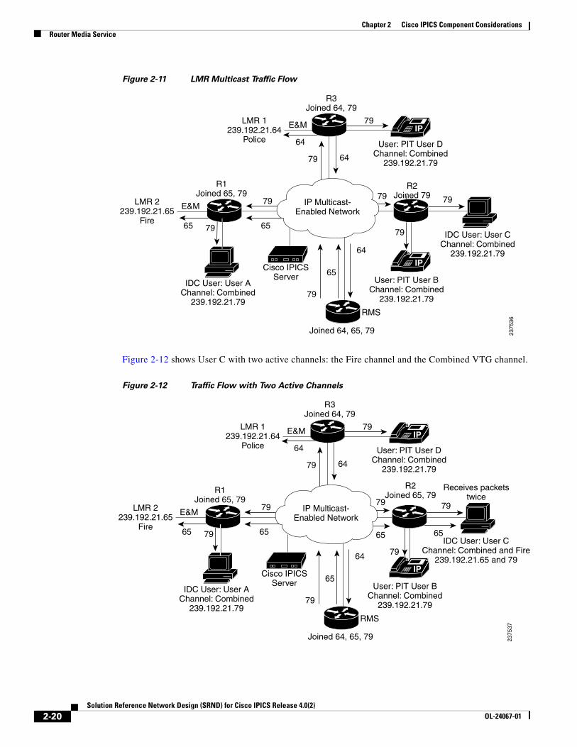
When the LMR Police user transmits, the only other endpoint that has joined this multicast channel is the RMS router. The multicast distribution tree forwards the multicast voice traffic to the RMS, where it is mixed with the Fire channel and the Combined VTG channel and then forwarded to the other endpoints in the VTG. See Figure 2-11.
IP
IP
IP Multicast-Enabled Network
R2Joined 79
R1Joined 65, 79
Joined 64, 65, 79
R3Joined 64, 79
2375
35
User: PIT User BChannel: Combined
239.192.21.79
IDC User: User AChannel: Combined
239.192.21.79
IDC User: User CChannel: Combined
239.192.21.79
User: PIT User DChannel: Combined
239.192.21.79
Cisco IPICSServer
E&MLMR 1239.192.21.64
Police
E&MLMR 2239.192.21.65
Fire
64
64
64
65
6565
RMS
2-19Solution Reference Network Design (SRND) for Cisco IPICS Release 4.0(2)
OL-24067-01
Chapter 2 Cisco IPICS Component ConsiderationsRouter Media Service
Figure 2-11 LMR Multicast Traffic Flow
Figure 2-12 shows User C with two active channels: the Fire channel and the Combined VTG channel.
Figure 2-12 Traffic Flow with Two Active Channels
79
7979
IP
IP
IP Multicast-Enabled Network
R2Joined 79
R1Joined 65, 79
Joined 64, 65, 79
R3Joined 64, 79
2375
36
User: PIT User BChannel: Combined
239.192.21.79
IDC User: User AChannel: Combined
239.192.21.79
IDC User: User CChannel: Combined
239.192.21.79
User: PIT User DChannel: Combined
239.192.21.79
Cisco IPICSServer
E&MLMR 1239.192.21.64
Police
E&MLMR 2239.192.21.65
Fire
64
64
6479
79
79
65
79
79
6565
RMS
79
79
79
IP
IP
IP Multicast-Enabled Network
R2Joined 65, 79
R1Joined 65, 79
Joined 64, 65, 79
R3Joined 64, 79
2375
37
User: PIT User BChannel: Combined
239.192.21.79
IDC User: User AChannel: Combined
239.192.21.79
IDC User: User CChannel: Combined and Fire
239.192.21.65 and 79
User: PIT User DChannel: Combined
239.192.21.79
Cisco IPICSServer
E&MLMR 1239.192.21.64
Police
E&MLMR 2239.192.21.65
Fire
64
64
6479
79
79
65
79
79
65 65 6565
Receives packetstwice
RMS
2-20Solution Reference Network Design (SRND) for Cisco IPICS Release 4.0(2)
OL-24067-01
Chapter 2 Cisco IPICS Component ConsiderationsRouter Media Service
Because User C activated two channels (Fire and the Combined VTG), two multicast groups are joined through IGMP. As a result, when an endpoint in the Combined VTG transmits, User C will receive the transmitted packets twice. (In this case, the duplicate packets can cause audio quality issues. Take care to avoid this scenario.)
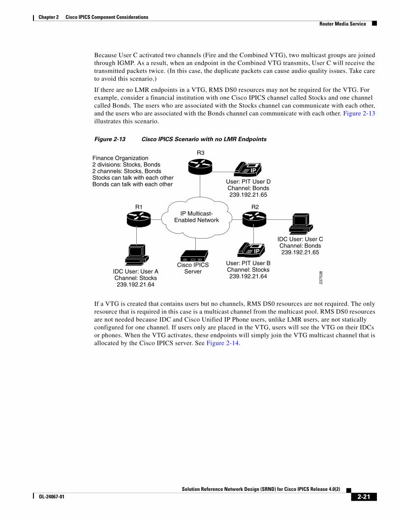
If there are no LMR endpoints in a VTG, RMS DS0 resources may not be required for the VTG. For example, consider a financial institution with one Cisco IPICS channel called Stocks and one channel called Bonds. The users who are associated with the Stocks channel can communicate with each other, and the users who are associated with the Bonds channel can communicate with each other. Figure 2-13 illustrates this scenario.
Figure 2-13 Cisco IPICS Scenario with no LMR Endpoints
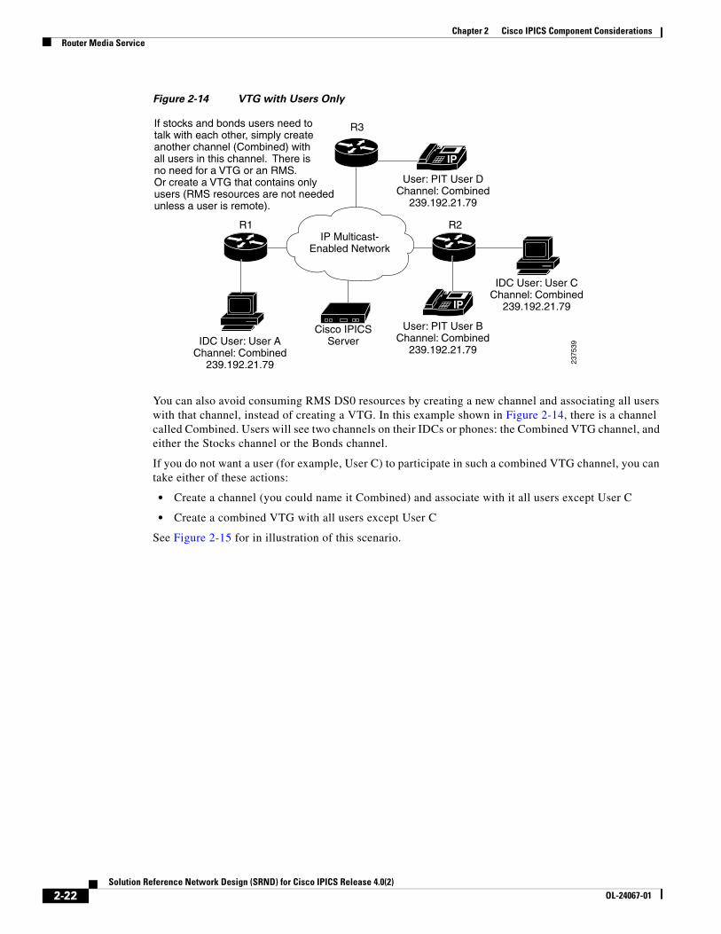
If a VTG is created that contains users but no channels, RMS DS0 resources are not required. The only resource that is required in this case is a multicast channel from the multicast pool. RMS DS0 resources are not needed because IDC and Cisco Unified IP Phone users, unlike LMR users, are not statically configured for one channel. If users only are placed in the VTG, users will see the VTG on their IDCs or phones. When the VTG activates, these endpoints will simply join the VTG multicast channel that is allocated by the Cisco IPICS server. See Figure 2-14.
IP
IP
IP Multicast-Enabled Network
R2R1
IDC User: User CChannel: Bonds239.192.21.65
User: PIT User DChannel: Bonds239.192.21.65
2375
38
User: PIT User BChannel: Stocks239.192.21.64
IDC User: User AChannel: Stocks239.192.21.64
Cisco IPICSServer
Finance Organization2 divisions: Stocks, Bonds2 channels: Stocks, BondsStocks can talk with each otherBonds can talk with each other
R3
2-21Solution Reference Network Design (SRND) for Cisco IPICS Release 4.0(2)
OL-24067-01
Chapter 2 Cisco IPICS Component ConsiderationsRouter Media Service
Figure 2-14 VTG with Users Only
You can also avoid consuming RMS DS0 resources by creating a new channel and associating all users with that channel, instead of creating a VTG. In this example shown in Figure 2-14, there is a channel called Combined. Users will see two channels on their IDCs or phones: the Combined VTG channel, and either the Stocks channel or the Bonds channel.
If you do not want a user (for example, User C) to participate in such a combined VTG channel, you can take either of these actions:
• Create a channel (you could name it Combined) and associate with it all users except User C
• Create a combined VTG with all users except User C
See Figure 2-15 for in illustration of this scenario.
IP
IP
IP Multicast-Enabled Network
R2R1
IDC User: User CChannel: Combined
239.192.21.79
User: PIT User DChannel: Combined
239.192.21.79
2375
39
User: PIT User BChannel: Combined
239.192.21.79IDC User: User A
Channel: Combined239.192.21.79
Cisco IPICSServer
If stocks and bonds users need totalk with each other, simply create another channel (Combined) withall users in this channel. There is no need for a VTG or an RMS.Or create a VTG that contains onlyusers (RMS resources are not neededunless a user is remote).
R3
2-22Solution Reference Network Design (SRND) for Cisco IPICS Release 4.0(2)
OL-24067-01
Chapter 2 Cisco IPICS Component ConsiderationsRouter Media Service
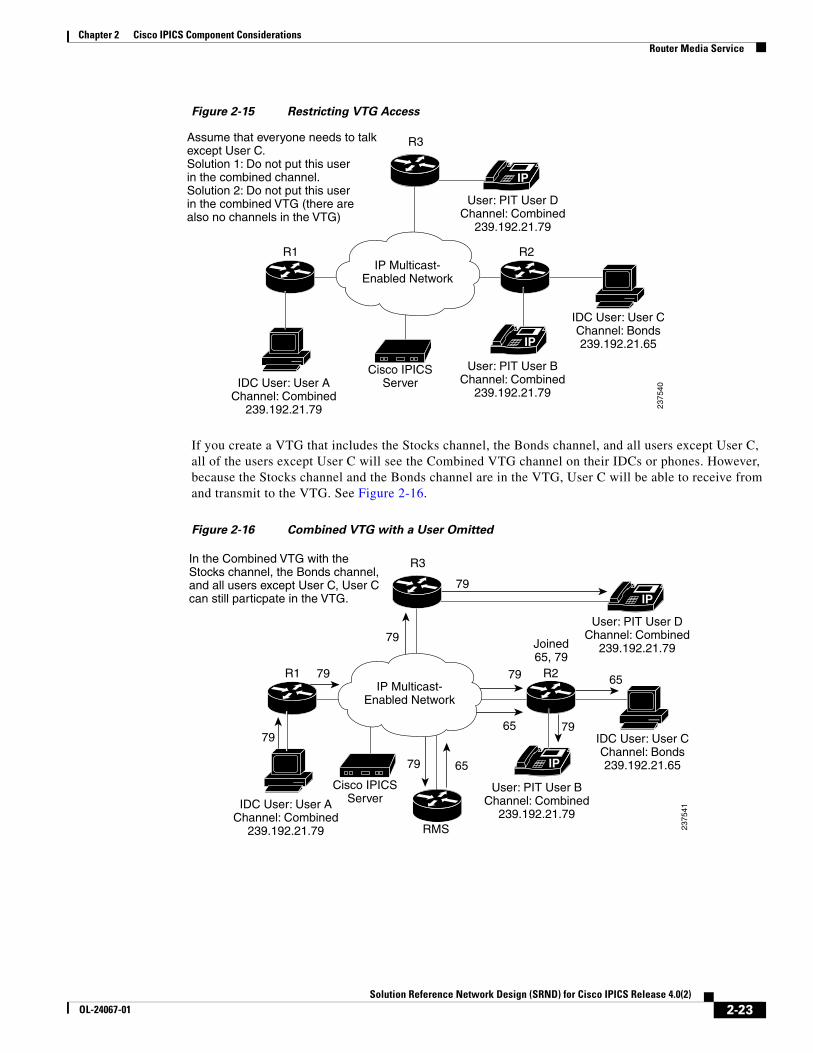
Figure 2-15 Restricting VTG Access
If you create a VTG that includes the Stocks channel, the Bonds channel, and all users except User C, all of the users except User C will see the Combined VTG channel on their IDCs or phones. However, because the Stocks channel and the Bonds channel are in the VTG, User C will be able to receive from and transmit to the VTG. See Figure 2-16.
Figure 2-16 Combined VTG with a User Omitted
IP
IP
IP Multicast-Enabled Network
R2R1
IDC User: User CChannel: Bonds239.192.21.65
User: PIT User DChannel: Combined
239.192.21.79
2375
40
User: PIT User BChannel: Combined
239.192.21.79IDC User: User A
Channel: Combined239.192.21.79
Cisco IPICSServer
Assume that everyone needs to talkexcept User C.Solution 1: Do not put this userin the combined channel.Solution 2: Do not put this userin the combined VTG (there arealso no channels in the VTG)
R3
IP
IP
IP Multicast-Enabled Network
R2R1
IDC User: User CChannel: Bonds239.192.21.65
User: PIT User DChannel: Combined
239.192.21.79
2375
41
User: PIT User BChannel: Combined
239.192.21.79IDC User: User A
Channel: Combined239.192.21.79
Cisco IPICSServer
In the Combined VTG with the Stocks channel, the Bonds channel,and all users except User C, User Ccan still particpate in the VTG.
R3
79
79
79
79
79
79
79 65
65
65
Joined65, 79
RMS
2-23Solution Reference Network Design (SRND) for Cisco IPICS Release 4.0(2)
OL-24067-01
Chapter 2 Cisco IPICS Component ConsiderationsRouter Media Service
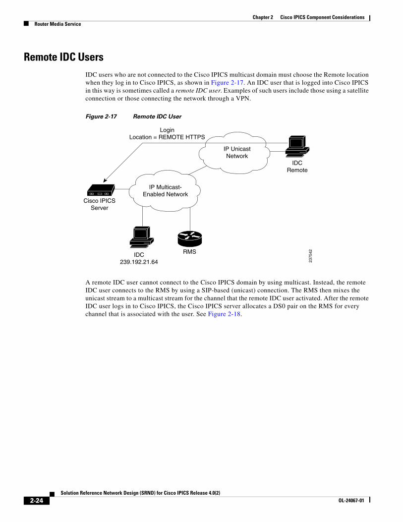
Remote IDC UsersIDC users who are not connected to the Cisco IPICS multicast domain must choose the Remote location when they log in to Cisco IPICS, as shown in Figure 2-17. An IDC user that is logged into Cisco IPICS in this way is sometimes called a remote IDC user. Examples of such users include those using a satellite connection or those connecting the network through a VPN.
Figure 2-17 Remote IDC User
A remote IDC user cannot connect to the Cisco IPICS domain by using multicast. Instead, the remote IDC user connects to the RMS by using a SIP-based (unicast) connection. The RMS then mixes the unicast stream to a multicast stream for the channel that the remote IDC user activated. After the remote IDC user logs in to Cisco IPICS, the Cisco IPICS server allocates a DS0 pair on the RMS for every channel that is associated with the user. See Figure 2-18.
IP Multicast-Enabled Network
IP UnicastNetwork
IDCRemote
IDC239.192.21.64
RMS
Cisco IPICSServer
LoginLocation = REMOTE HTTPS
2375
42
2-24Solution Reference Network Design (SRND) for Cisco IPICS Release 4.0(2)
OL-24067-01
Chapter 2 Cisco IPICS Component ConsiderationsRouter Media Service
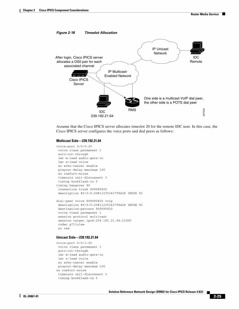
Figure 2-18 Timeslot Allocation
Assume that the Cisco IPICS server allocates timeslot 20 for the remote IDC user. In this case, the Cisco IPICS server configures the voice ports and dial peers as follows:
Multicast Side—239.192.21.64voice-port 0/0/0:20 voice class permanent 1 auto-cut-through lmr m-lead audio-gate-in lmr e-lead voice no echo-cancel enable playout-delay maximum 100 no comfort-noise timeouts call-disconnect 3 timing hookflash-in 0timing hangover 80 connection trunk 909090920 description #0/0/0:20#1123534375842# INUSE 92
dial-peer voice 909090920 voip description #0/0/0:20#1123534375842# INUSE 92 destination-pattern 909090920 voice class permanent 1 session protocol multicast session target ipv4:239.192.21.64:21000 codec g711ulaw no vad
Unicast Side—239.192.21.64voice-port 0/0/1:20 voice class permanent 1 auto-cut-through lmr m-lead audio-gate-in lmr e-lead voice no echo-cancel enable playout-delay maximum 100no comfort-noise timeouts call-disconnect 3 timing hookflash-in 0
IP Multicast-Enabled Network
IP UnicastNetwork
IDCRemote
IDC239.192.21.64
RMS
Cisco IPICSServer
2375
43
One side is a multicast VoIP dial peer,the other side is a POTS dial peer
After login, Cisco IPICS serverallocates a DS0 pair for each
associated channel
2-25Solution Reference Network Design (SRND) for Cisco IPICS Release 4.0(2)
OL-24067-01
Chapter 2 Cisco IPICS Component ConsiderationsRouter Media Service
timing hangover 80 description #0/0/1:20#1123534375842# INUSE 92
dial-peer voice 909091920 pots description #0/0/1:20#1123534375842# INUSE 92 destination-pattern 8880000081909091920 port 0/0/1:20
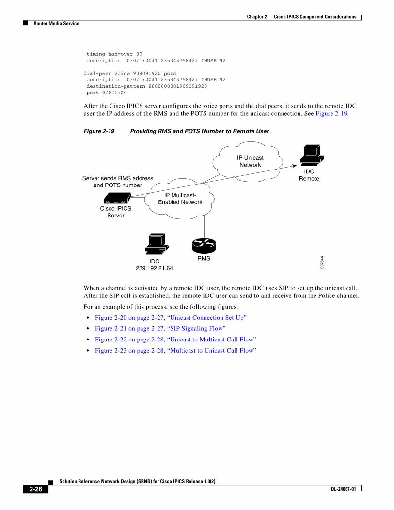
After the Cisco IPICS server configures the voice ports and the dial peers, it sends to the remote IDC user the IP address of the RMS and the POTS number for the unicast connection. See Figure 2-19.
Figure 2-19 Providing RMS and POTS Number to Remote User
When a channel is activated by a remote IDC user, the remote IDC uses SIP to set up the unicast call. After the SIP call is established, the remote IDC user can send to and receive from the Police channel.
For an example of this process, see the following figures:
• Figure 2-20 on page 2-27, “Unicast Connection Set Up”
• Figure 2-21 on page 2-27, “SIP Signaling Flow”
• Figure 2-22 on page 2-28, “Unicast to Multicast Call Flow”
• Figure 2-23 on page 2-28, “Multicast to Unicast Call Flow”
IP Multicast-Enabled Network
IP UnicastNetwork
IDCRemote
IDC239.192.21.64
RMS
Cisco IPICSServer
2375
44
Server sends RMS addressand POTS number
2-26Solution Reference Network Design (SRND) for Cisco IPICS Release 4.0(2)
OL-24067-01
Chapter 2 Cisco IPICS Component ConsiderationsRouter Media Service
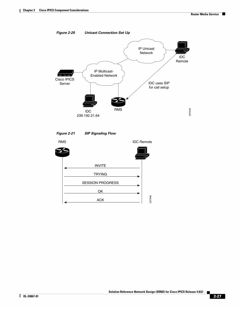
Figure 2-20 Unicast Connection Set Up
Figure 2-21 SIP Signaling Flow
IP Multicast-Enabled Network
IP UnicastNetwork
IDCRemote
IDC239.192.21.64
RMS
Cisco IPICSServer
2375
45
IDC uses SIPfor call setup
RMS IDC Remote
INVITE
TRYING
SESSION PROGRESS
OK
ACK
2375
46
2-27Solution Reference Network Design (SRND) for Cisco IPICS Release 4.0(2)
OL-24067-01
Chapter 2 Cisco IPICS Component ConsiderationsRouter Media Service
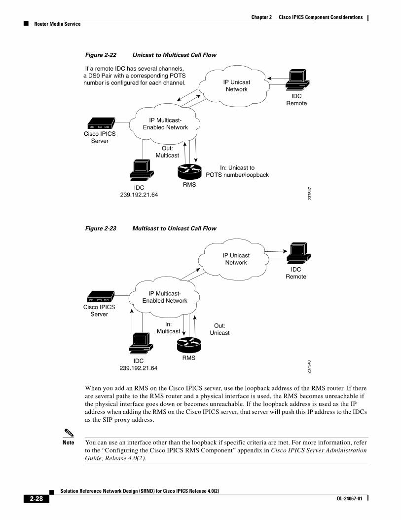
Figure 2-22 Unicast to Multicast Call Flow
Figure 2-23 Multicast to Unicast Call Flow
When you add an RMS on the Cisco IPICS server, use the loopback address of the RMS router. If there are several paths to the RMS router and a physical interface is used, the RMS becomes unreachable if the physical interface goes down or becomes unreachable. If the loopback address is used as the IP address when adding the RMS on the Cisco IPICS server, that server will push this IP address to the IDCs as the SIP proxy address.
Note You can use an interface other than the loopback if specific criteria are met. For more information, refer to the “Configuring the Cisco IPICS RMS Component” appendix in Cisco IPICS Server Administration Guide, Release 4.0(2).
IP Multicast-Enabled Network
IP UnicastNetwork
IDCRemote
IDC239.192.21.64
RMS
Cisco IPICSServer
2375
47
In: Unicast toPOTS number/loopback
Out:Multicast
If a remote IDC has several channels,a DS0 Pair with a corresponding POTSnumber is configured for each channel.
In:Multicast
IP Multicast-Enabled Network
IP UnicastNetwork
IDCRemote
IDC239.192.21.64
RMS
Cisco IPICSServer
2375
48
Out:Unicast
2-28Solution Reference Network Design (SRND) for Cisco IPICS Release 4.0(2)
OL-24067-01
Chapter 2 Cisco IPICS Component ConsiderationsIntegrating Cisco IPICS with SIP Providers
Integrating Cisco IPICS with SIP ProvidersThe Cisco IPICS dial engine requires a SIP provider to place or receive calls. See Cisco IPICS Compatibility Matrix for a list of supported SIP providers (Cisco Unified Communications Manager or Cisco Unified Communications Manager Express with a router running a supported Cisco IOS release).
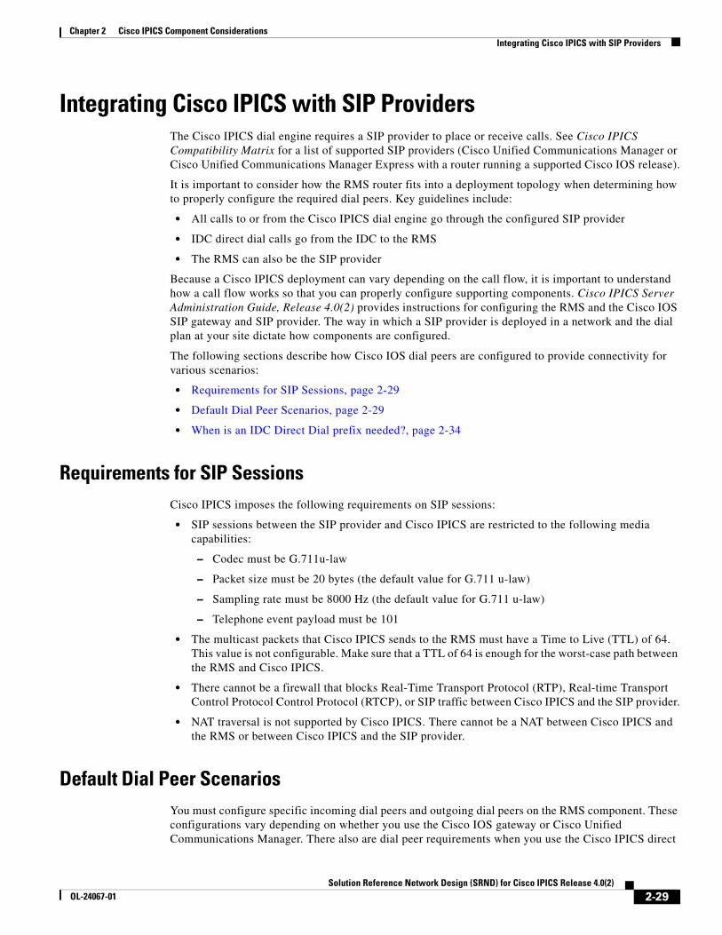
It is important to consider how the RMS router fits into a deployment topology when determining how to properly configure the required dial peers. Key guidelines include:
• All calls to or from the Cisco IPICS dial engine go through the configured SIP provider
• IDC direct dial calls go from the IDC to the RMS
• The RMS can also be the SIP provider
Because a Cisco IPICS deployment can vary depending on the call flow, it is important to understand how a call flow works so that you can properly configure supporting components. Cisco IPICS Server Administration Guide, Release 4.0(2) provides instructions for configuring the RMS and the Cisco IOS SIP gateway and SIP provider. The way in which a SIP provider is deployed in a network and the dial plan at your site dictate how components are configured.
The following sections describe how Cisco IOS dial peers are configured to provide connectivity for various scenarios:
• Requirements for SIP Sessions, page 2-29
• Default Dial Peer Scenarios, page 2-29
• When is an IDC Direct Dial prefix needed?, page 2-34
Requirements for SIP SessionsCisco IPICS imposes the following requirements on SIP sessions:
• SIP sessions between the SIP provider and Cisco IPICS are restricted to the following media capabilities:
– Codec must be G.711u-law
– Packet size must be 20 bytes (the default value for G.711 u-law)
– Sampling rate must be 8000 Hz (the default value for G.711 u-law)
– Telephone event payload must be 101
• The multicast packets that Cisco IPICS sends to the RMS must have a Time to Live (TTL) of 64. This value is not configurable. Make sure that a TTL of 64 is enough for the worst-case path between the RMS and Cisco IPICS.
• There cannot be a firewall that blocks Real-Time Transport Protocol (RTP), Real-time Transport Control Protocol Control Protocol (RTCP), or SIP traffic between Cisco IPICS and the SIP provider.
• NAT traversal is not supported by Cisco IPICS. There cannot be a NAT between Cisco IPICS and the RMS or between Cisco IPICS and the SIP provider.
Default Dial Peer ScenariosYou must configure specific incoming dial peers and outgoing dial peers on the RMS component. These configurations vary depending on whether you use the Cisco IOS gateway or Cisco Unified Communications Manager. There also are dial peer requirements when you use the Cisco IPICS direct
2-29Solution Reference Network Design (SRND) for Cisco IPICS Release 4.0(2)
OL-24067-01
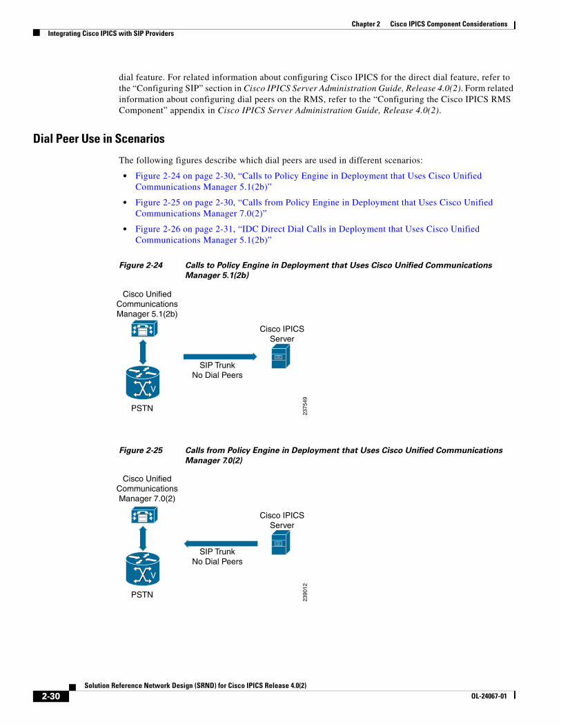
Chapter 2 Cisco IPICS Component ConsiderationsIntegrating Cisco IPICS with SIP Providers
dial feature. For related information about configuring Cisco IPICS for the direct dial feature, refer to the “Configuring SIP” section in Cisco IPICS Server Administration Guide, Release 4.0(2). Form related information about configuring dial peers on the RMS, refer to the “Configuring the Cisco IPICS RMS Component” appendix in Cisco IPICS Server Administration Guide, Release 4.0(2).
Dial Peer Use in Scenarios
The following figures describe which dial peers are used in different scenarios:
• Figure 2-24 on page 2-30, “Calls to Policy Engine in Deployment that Uses Cisco Unified Communications Manager 5.1(2b)”
• Figure 2-25 on page 2-30, “Calls from Policy Engine in Deployment that Uses Cisco Unified Communications Manager 7.0(2)”
• Figure 2-26 on page 2-31, “IDC Direct Dial Calls in Deployment that Uses Cisco Unified Communications Manager 5.1(2b)”
Figure 2-24 Calls to Policy Engine in Deployment that Uses Cisco Unified Communications
Manager 5.1(2b)
Figure 2-25 Calls from Policy Engine in Deployment that Uses Cisco Unified Communications
Manager 7.0(2)
V
Cisco UnifiedCommunicationsManager 5.1(2b)
PSTN
SIP TrunkNo Dial Peers
Cisco IPICSServer
2375
49
V
Cisco UnifiedCommunicationsManager 7.0(2)
PSTN
SIP TrunkNo Dial Peers
Cisco IPICSServer
2390
12
2-30Solution Reference Network Design (SRND) for Cisco IPICS Release 4.0(2)
OL-24067-01
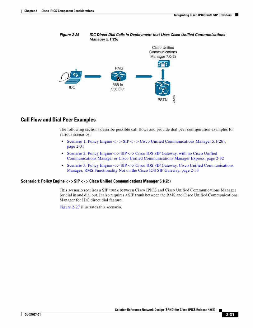
Chapter 2 Cisco IPICS Component ConsiderationsIntegrating Cisco IPICS with SIP Providers
Figure 2-26 IDC Direct Dial Calls in Deployment that Uses Cisco Unified Communications
Manager 5.1(2b)
Call Flow and Dial Peer Examples
The following sections describe possible call flows and provide dial peer configuration examples for various scenarios:
• Scenario 1: Policy Engine < - > SIP < - > Cisco Unified Communications Manager 5.1(2b), page 2-31
• Scenario 2: Policy Engine <-> SIP <-> Cisco IOS SIP Gateway, with no Cisco Unified Communications Manager or Cisco Unified Communications Manager Express, page 2-32
• Scenario 3: Policy Engine <-> SIP <-> Cisco IOS SIP Gateway, Cisco Unified Communications Manager, RMS Functionality Not on the Cisco IOS SIP Gateway, page 2-33
Scenario 1: Policy Engine < - > SIP < - > Cisco Unified Communications Manager 5.1(2b)
This scenario requires a SIP trunk between Cisco IPICS and Cisco Unified Communications Manager for dial in and dial out. It also requires a SIP trunk between the RMS and Cisco Unified Communications Manager for IDC direct dial feature.
Figure 2-27 illustrates this scenario.
V
Cisco UnifiedCommunicationsManager 7.0(2)
PSTN
RMS
2390
13
V555 In
556 OutIDC
2-31Solution Reference Network Design (SRND) for Cisco IPICS Release 4.0(2)
OL-24067-01
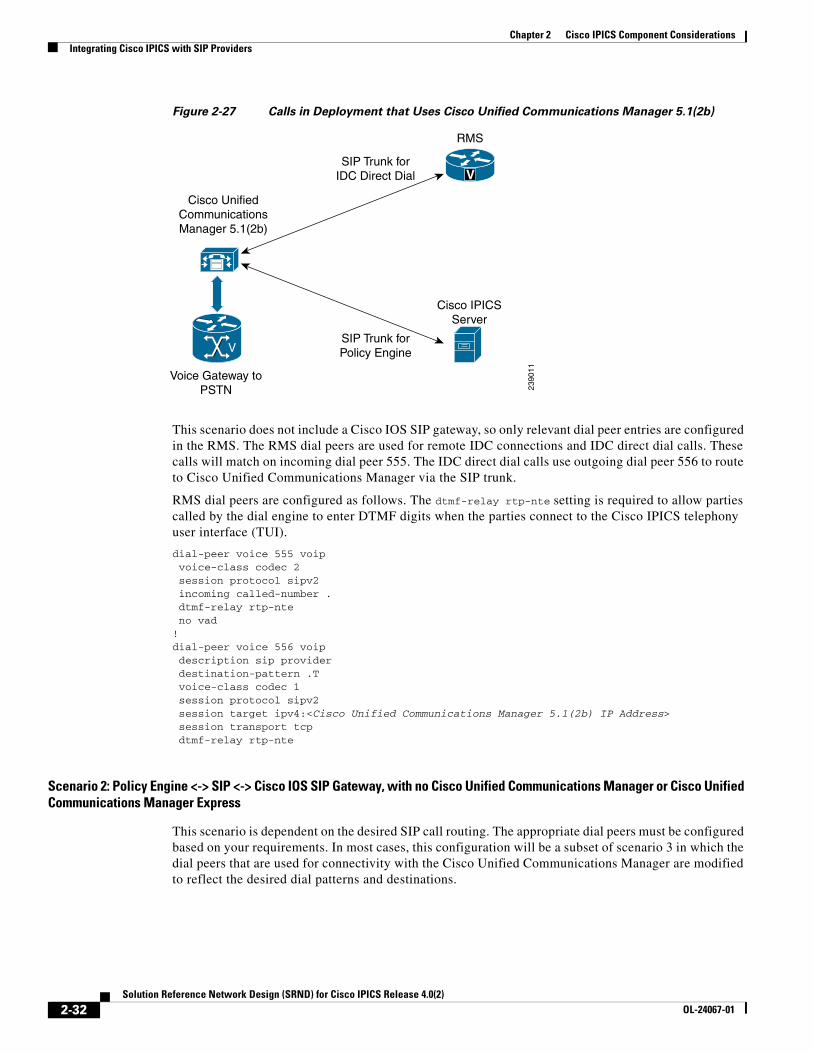
Chapter 2 Cisco IPICS Component ConsiderationsIntegrating Cisco IPICS with SIP Providers
Figure 2-27 Calls in Deployment that Uses Cisco Unified Communications Manager 5.1(2b)
This scenario does not include a Cisco IOS SIP gateway, so only relevant dial peer entries are configured in the RMS. The RMS dial peers are used for remote IDC connections and IDC direct dial calls. These calls will match on incoming dial peer 555. The IDC direct dial calls use outgoing dial peer 556 to route to Cisco Unified Communications Manager via the SIP trunk.
RMS dial peers are configured as follows. The dtmf-relay rtp-nte setting is required to allow parties called by the dial engine to enter DTMF digits when the parties connect to the Cisco IPICS telephony user interface (TUI).
dial-peer voice 555 voip voice-class codec 2 session protocol sipv2 incoming called-number . dtmf-relay rtp-nte no vad!dial-peer voice 556 voip description sip provider destination-pattern .T voice-class codec 1 session protocol sipv2 session target ipv4:<Cisco Unified Communications Manager 5.1(2b) IP Address> session transport tcp dtmf-relay rtp-nte
Scenario 2: Policy Engine <-> SIP <-> Cisco IOS SIP Gateway, with no Cisco Unified Communications Manager or Cisco Unified Communications Manager Express
This scenario is dependent on the desired SIP call routing. The appropriate dial peers must be configured based on your requirements. In most cases, this configuration will be a subset of scenario 3 in which the dial peers that are used for connectivity with the Cisco Unified Communications Manager are modified to reflect the desired dial patterns and destinations.
V
Cisco UnifiedCommunicationsManager 5.1(2b)
Voice Gateway toPSTN 23
9011
RMS
V
Cisco IPICSServer
SIP Trunk forPolicy Engine
SIP Trunk forIDC Direct Dial
2-32Solution Reference Network Design (SRND) for Cisco IPICS Release 4.0(2)
OL-24067-01
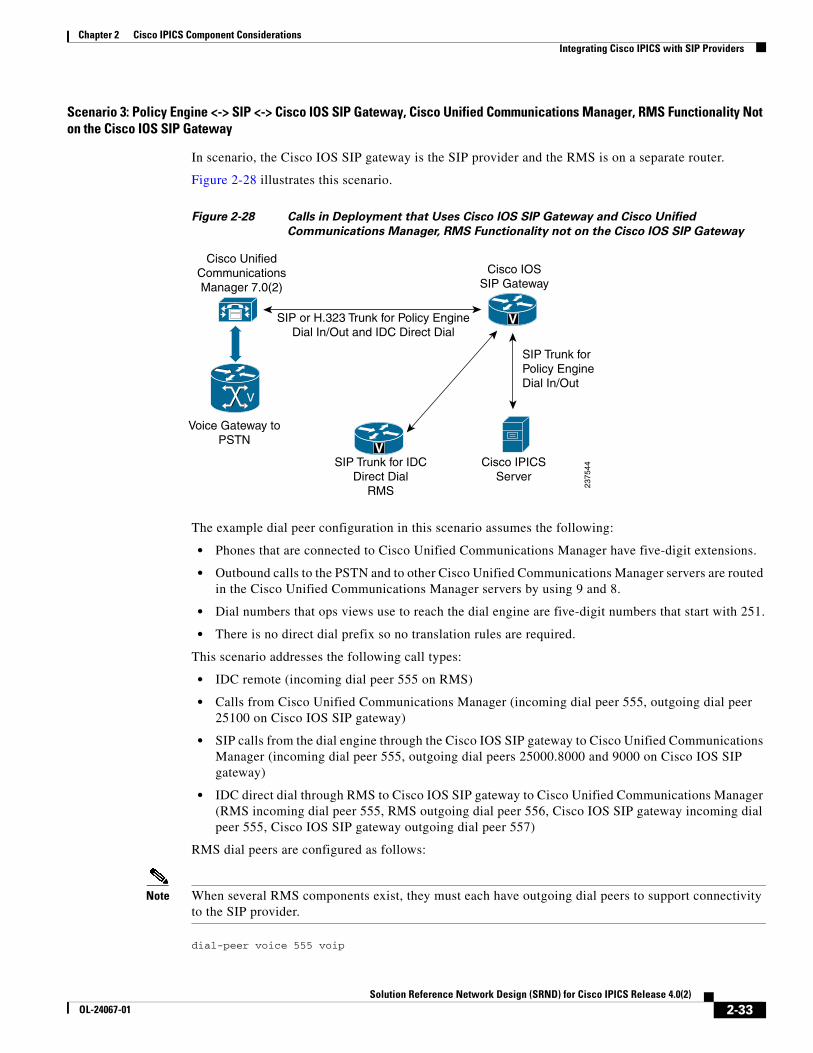
Chapter 2 Cisco IPICS Component ConsiderationsIntegrating Cisco IPICS with SIP Providers
Scenario 3: Policy Engine <-> SIP <-> Cisco IOS SIP Gateway, Cisco Unified Communications Manager, RMS Functionality Not on the Cisco IOS SIP Gateway
In scenario, the Cisco IOS SIP gateway is the SIP provider and the RMS is on a separate router.
Figure 2-28 illustrates this scenario.
Figure 2-28 Calls in Deployment that Uses Cisco IOS SIP Gateway and Cisco Unified
Communications Manager, RMS Functionality not on the Cisco IOS SIP Gateway
The example dial peer configuration in this scenario assumes the following:
• Phones that are connected to Cisco Unified Communications Manager have five-digit extensions.
• Outbound calls to the PSTN and to other Cisco Unified Communications Manager servers are routed in the Cisco Unified Communications Manager servers by using 9 and 8.
• Dial numbers that ops views use to reach the dial engine are five-digit numbers that start with 251.
• There is no direct dial prefix so no translation rules are required.
This scenario addresses the following call types:
• IDC remote (incoming dial peer 555 on RMS)
• Calls from Cisco Unified Communications Manager (incoming dial peer 555, outgoing dial peer 25100 on Cisco IOS SIP gateway)
• SIP calls from the dial engine through the Cisco IOS SIP gateway to Cisco Unified Communications Manager (incoming dial peer 555, outgoing dial peers 25000.8000 and 9000 on Cisco IOS SIP gateway)
• IDC direct dial through RMS to Cisco IOS SIP gateway to Cisco Unified Communications Manager (RMS incoming dial peer 555, RMS outgoing dial peer 556, Cisco IOS SIP gateway incoming dial peer 555, Cisco IOS SIP gateway outgoing dial peer 557)
RMS dial peers are configured as follows:
Note When several RMS components exist, they must each have outgoing dial peers to support connectivity to the SIP provider.
dial-peer voice 555 voip
V
Cisco UnifiedCommunicationsManager 7.0(2)
Voice Gateway toPSTN
2375
44
V
V
SIP Trunk forPolicy EngineDial In/Out
Cisco IOSSIP Gateway
SIP or H.323 Trunk for Policy EngineDial In/Out and IDC Direct Dial
Cisco IPICSServer
SIP Trunk for IDCDirect Dial
RMS
2-33Solution Reference Network Design (SRND) for Cisco IPICS Release 4.0(2)
OL-24067-01
Chapter 2 Cisco IPICS Component ConsiderationsIntegrating Cisco IPICS with SIP Providers
voice-class codec 2 session protocol sipv2 incoming called-number . dtmf-relay rtp-nte no vad!dial-peer voice 556 voip destination-pattern .T voice-class codec 1 session protocol sipv2 session target ipv4:<Cisco IOS SIP Gateway IP Address> session transport tcp dtmf-relay rtp-nte
Cisco IOS SIP gateway dial peers are configured as follows:
dial-peer voice 555 voip voice-class codec 2 session protocol sipv2 incoming called-number . dtmf-relay rtp-nte no vad!dial-peer voice 25000 voip destination-pattern ..... voice-class codec 1 session target ipv4:<Cisco Unified Communications Manager 4.1 IP Address> session transport tcp dtmf-relay h245-alphanumeric!dial-peer voice 9000 voip destination-pattern 9T voice-class codec 2 session target ipv4:<Cisco Unified Communications Manager 4.1 IP Address> dtmf-relay h245-alphanumeric!dial-peer voice 8000 voip destination-pattern 8T voice-class codec 2 session target ipv4:<Cisco Unified Communications Manager 4.1 IP Address> dtmf-relay h245-alphanumeric!dial-peer voice 25100 voip destination-pattern 251.. session protocol sipv2 session target ipv4:<Cisco IPICS Server IP Address> session transport tcp dtmf-relay rtp-nte
When is an IDC Direct Dial prefix needed?A Direct Dial prefix is an optional digit string that the server prepends to each direct dial number when it dials the number. Using a dial prefix can help to avoid dial plan conflicts. For example, if the dial prefix string is 9 and the direct dial destination number is 1234, the number 91234 is dialed.
Because the IDC direct dial feature always uses the RMS as a proxy, there may be cases where a unique dial pattern is required to perform digit manipulation on dialed strings so that they can be differentiated from other calls that do not require digit manipulation.
2-34Solution Reference Network Design (SRND) for Cisco IPICS Release 4.0(2)
OL-24067-01
Chapter 2 Cisco IPICS Component ConsiderationsIDC Dialer Configuration and Integration with Unified Communications Platform
In these cases, you can employ a combination of dial peers and translation rules in the RMS to manipulate the digits before they are sent to the desired destination.
The following example configures a translation rule for the outgoing dial peer in the RMS. This configuration allows the use of a direct dial prefix for the direct dial feature. Although this configuration is required for most scenarios, the default configuration allows for a dial prefix of 9, which is removed by the following RMS configuration.
voice translation-rule 1 rule 1 /^9\(.*\)$/ /\1/voice translation-profile 1 translate called 1
dial-peer voice 556 voipdestination-pattern 9T translation-profile outgoing 1 preference 10 voice-class codec 1 session protocol sipv2 session target ipv4:<SIP Provider IP Address> session transport tcp dtmf-relay rtp-nte
IDC Dialer Configuration and Integration with Unified Communications Platform
The IDC dialer functionality enables users with the Cisco IPICS Dispatcher role to make and receive PSTN calls and patch a VTG, channel, or incident to a PSTN user. The IDC dialer provides two lines, which can be used separately.
Setting up the IDC dialer functionality involves these general steps:
• Configuring an IDC dialer endpoint in Cisco Unified Communications Manager or Cisco Unified Communications Manage Express
• Configuring the IDC dialer in Cisco IPICS
To configure the IDC dialer, you must obtain the following information:
• The IP address of the Cisco Unified Call Manager or Cisco Unified Call Manager Express that you will use
• A directory number (DN) for each Cisco IPICS dispatcher that will use the IDC dialer
• The user name and password that are configured for the DN in Cisco Unified Call Manager and Cisco Unified Call Manager Express
The following sections provide information about configuring the IDC dialer feature and describe how to integrate this feature with Cisco Unified Communications Manager and Cisco Unified Communications Manager Express:
• Configuring an IDC Dialer End Point on Cisco Unified Communications Manager, page 2-36
• Configuring an IDC Dialer End Point on Cisco Unified Communications Manager Express, page 2-36
• Configuring the IDC Dialer in the Cisco IPICS Administration Console, page 2-37
2-35Solution Reference Network Design (SRND) for Cisco IPICS Release 4.0(2)
OL-24067-01
Chapter 2 Cisco IPICS Component ConsiderationsIDC Dialer Configuration and Integration with Unified Communications Platform
Configuring an IDC Dialer End Point on Cisco Unified Communications ManagerThis section explains how to configure an IDC Dialer endpoint in Cisco Unified Communications Manager. You must configure such and end point for each Cisco IPICS dispatcher who will use the IDC Dialer.
Procedure
Step 1 Log in to the Cisco Unified Communications Manager Administration console.
Step 2 Take these actions to configure an end user, which will be an IDC Dialer end point:
a. Choose User Management > End User.
b. Choose the Add New tab.
c. Configure the end user. At a minimum, enter information in the User ID, Password, Confirm Password, and Last Name fields.
d. Click Save
Step 3 Take these actions to configure a phone with the DN that the IDC dialer requires:
a. Choose Device > Phone.
b. Click Add New.
c. From the Phone Type drop-down list, choose Third-Party SIP Device Basic.
d. Make configuration settings as appropriate.
The MAC can be a unique dummy address.
In the Owner User ID and Digest User fields, choose the use ID that you configured in Step 2.
From the SIP Profile drop-down list, choose Standard SIP Profile.
e. Click Save.
Step 4 In the Association Information area, click Line [1] - Add a new DN and configure the DN for the phone with the DN you want to use and save the configuration.
Step 5 Perform this procedure for each Cisco IPICS dispatcher who will use the IDC dialer.
Configuring an IDC Dialer End Point on Cisco Unified Communications Manager Express
The following example shows how to configure an IDC dialer endpoint in Cisco Unified Communications Manager Express. You must configure such and end point for each Cisco IPICS dispatcher who will use the IDC Dialer.
voice register dn 1 number 4100!voice register pool 2 id mac 0000.0000.0000 number 1 dn 2 dtmf-relay rtp-nte voice-class codec 1 username dispatch password cisco
2-36Solution Reference Network Design (SRND) for Cisco IPICS Release 4.0(2)
OL-24067-01
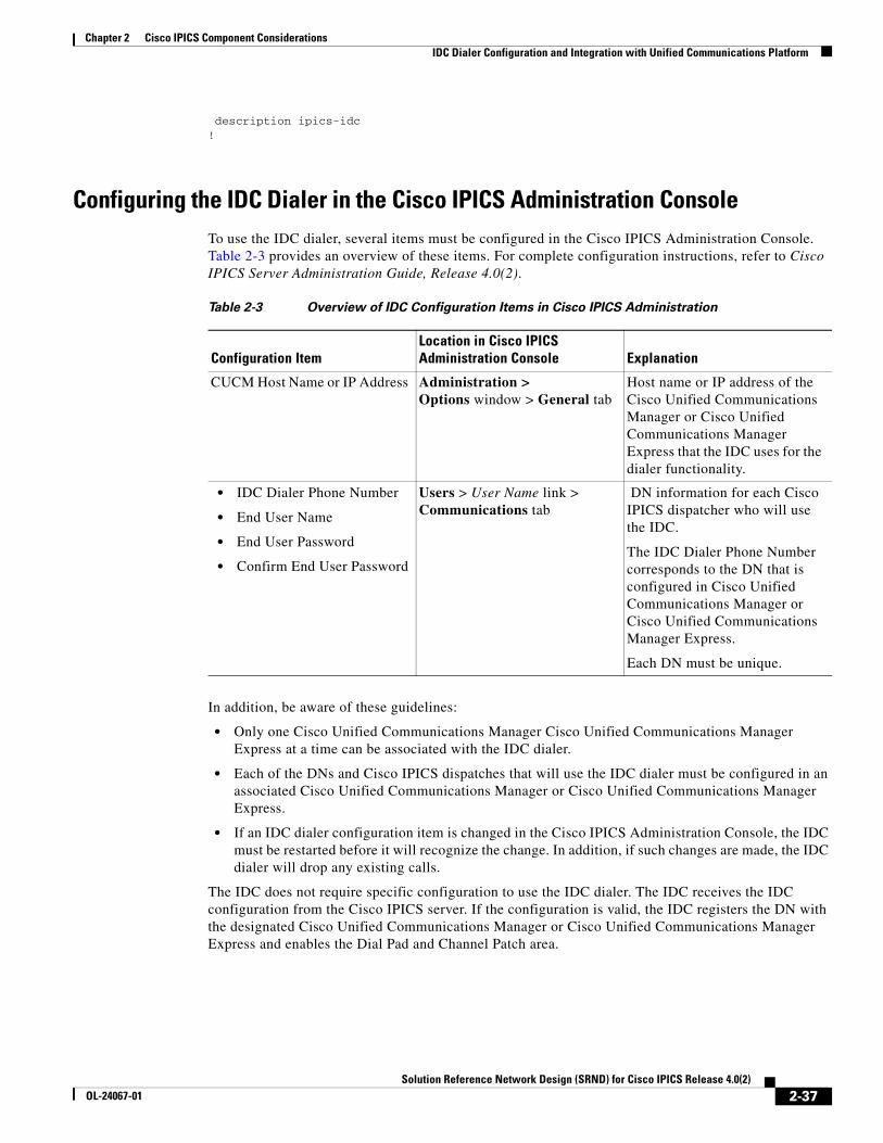
Chapter 2 Cisco IPICS Component ConsiderationsIDC Dialer Configuration and Integration with Unified Communications Platform
description ipics-idc!
Configuring the IDC Dialer in the Cisco IPICS Administration ConsoleTo use the IDC dialer, several items must be configured in the Cisco IPICS Administration Console. Table 2-3 provides an overview of these items. For complete configuration instructions, refer to Cisco IPICS Server Administration Guide, Release 4.0(2).
In addition, be aware of these guidelines:
• Only one Cisco Unified Communications Manager Cisco Unified Communications Manager Express at a time can be associated with the IDC dialer.
• Each of the DNs and Cisco IPICS dispatches that will use the IDC dialer must be configured in an associated Cisco Unified Communications Manager or Cisco Unified Communications Manager Express.
• If an IDC dialer configuration item is changed in the Cisco IPICS Administration Console, the IDC must be restarted before it will recognize the change. In addition, if such changes are made, the IDC dialer will drop any existing calls.
The IDC does not require specific configuration to use the IDC dialer. The IDC receives the IDC configuration from the Cisco IPICS server. If the configuration is valid, the IDC registers the DN with the designated Cisco Unified Communications Manager or Cisco Unified Communications Manager Express and enables the Dial Pad and Channel Patch area.
Table 2-3 Overview of IDC Configuration Items in Cisco IPICS Administration
Configuration ItemLocation in Cisco IPICS Administration Console Explanation
CUCM Host Name or IP Address Administration > Options window > General tab
Host name or IP address of the Cisco Unified Communications Manager or Cisco Unified Communications Manager Express that the IDC uses for the dialer functionality.
• IDC Dialer Phone Number
• End User Name
• End User Password
• Confirm End User Password
Users > User Name link > Communications tab
DN information for each Cisco IPICS dispatcher who will use the IDC.
The IDC Dialer Phone Number corresponds to the DN that is configured in Cisco Unified Communications Manager or Cisco Unified Communications Manager Express.
Each DN must be unique.
2-37Solution Reference Network Design (SRND) for Cisco IPICS Release 4.0(2)
OL-24067-01
Chapter 2 Cisco IPICS Component ConsiderationsCisco IPICS Mobile Client for Apple iPhone
Cisco IPICS Mobile Client for Apple iPhoneThe IPICS Mobile Client is an application for the Apple iPhone that allows you to use an iPhone to interact with other participants in a Cisco IP Interoperability and Collaboration System (IPICS) incident. The iPhone can communicate with Cisco IPICS either via a WiFi network connection or a 3G connection by using the Cisco Incident app. For detailed information about this application, and information about feature limits when using a WiFi connection, refer to Cisco IPICS Mobile Client for Apple iPhone Reference Guide.
When using the iPhone as a mobile client, be aware of the following:
• If you are using a WiFi connection, the Cisco IPICS server and the RMS component must be accessible on the wireless network.
• Network connectivity for all Cisco IPICS components that are to be used with the mobile client should be established before using the mobile client.
• The Incident App PTT feature is supported only on WiFi networks.
• Uploading photographs and video clips over a 3G connection can be extremely slow, depending on the ISP that the iPhone us using.
• When you view a list of incidents or a list of resources in an incident, the information in the screen updates automatically. The update interval is defined by the IDC Update Poll option in the Administration > Options > IDC/Client tab in the Cisco IPCS Administration Console. The default update interval is 5 seconds.
The following sections provide related information:
• DNS Configuration, page 2-38
• Wireless Network Configurations, page 2-41
• Wireless Configuration on an iPhone, page 2-46
DNS ConfigurationThe mobile client uses SSL to communicate with the server. SSL requires that DNS be enabled in your network.
The following sections provide information about the models that you can use to configure DNS in you network.
• Intranet Access Model, page 2-38
• Internet/Intranet Access Model, page 2-39
Intranet Access Model
This section provides guidelines for how to configure DNS when an iPhone will connect to an IPICS server only on a local intranet.
• Ensure that a DNS server is configured in your LAN.
• Configure each component in the Cisco IPICS component to us this DNS server for hostname resolution.
• Configure the hostname for the DNS server as an entry in the DNS server.
• Do not use the Hosts file on an IDC client PC to bypass the DNS name resolution.
2-38Solution Reference Network Design (SRND) for Cisco IPICS Release 4.0(2)
OL-24067-01
Chapter 2 Cisco IPICS Component ConsiderationsCisco IPICS Mobile Client for Apple iPhone
• Ensure that you can ping the Cisco IPICS server by its hostname from each IDC client PC.
• If you are using DHCP for IP address assignments, ensure that the correct search domain is configured on the DHCP server or the wireless controller that is acting as a DCHP server. The search domain is not populated automatically.
• If you are not using DHCP for IP address assignment, ensure that the correct domain name and client ID are configured on the iPhone. Also, ensure that you populate the DNS server address on the iPhone in addition to the IP address, mask, and default gateway values. For information about how to configure these options on an iPhone, see the “Wireless Configuration on an iPhone” section on page 2-46.
DHCP servers use the client ID to bind the iPhone to a specific IP address. This binding ensures that the iPhone can communicates through firewalls, and access restrictions (Access Control Lists) in your network. If you do not configure a client ID, you cannot access the Incident app on an iPhone.
Internet/Intranet Access Model
This section provides guidelines for how to configure DNS when an iPhone will connect to an IPICS server via the Internet and a local intranet.
• Ensure that a DNS server is configured in your LAN.
• Configure each component in the Cisco IPICS component to us this DNS server for hostname resolution.
• Configure the hostname for the DNS server as an entry in the DNS server.
• Do not use the Hosts file on an IDC client PC to bypass the DNS name resolution.
• Ensure that you can ping the Cisco IPICS server by its hostname from each IDC client PC.
• If you are using DHCP for IP address assignments, ensure that the correct search domain is configured on the DHCP server or the wireless controller that is acting as a DCHP server. The search domain is not populated automatically.
• If you are not using DHCP for IP address assignment, ensure that the correct domain name and client ID are configured on the iPhone. Also, ensure that you populate the DNS server address on the iPhone in addition to the IP address, mask, and default gateway values For information about how to configure these options on an iPhone, see the “Wireless Configuration on an iPhone” section on page 2-46.
DHCP servers use the client ID to bind the iPhone to a specific IP address. This binding ensures that the iPhone can communicates through firewalls, and access restrictions (Access Control Lists) in your network. If you do not configure a client ID, you cannot access the Incident app on an iPhone.
• If you are not using the DHCP Server for IP Address assignment, then you also need to ensure that you populate the DNS Server address on the iPhone in addition to the IP Address, Mask and Default Gateway that you may specify.
• If the mobile client needs to access two domains (one for the intranet and one for the Internet), the intranet DNS must be configured to forward requests from the mobile client to the Internet DNS, and the Internet DNS must be configured to forward requests to the intranet DNS.
• If the Cisco IPICS server is reachable on the Internet and has a FQDN registered on the web, any Internet DNS can be used to resolve the IP address of the server. In such a scenario, the local DNS should configured with the DNS address that is provided by the local ISP. Alternatively, you can use a public DNS, such as 4.2.2.2 and 8.2.2.2, ro provide name resolution.
2-39Solution Reference Network Design (SRND) for Cisco IPICS Release 4.0(2)
OL-24067-01
Chapter 2 Cisco IPICS Component ConsiderationsCisco IPICS Mobile Client for Apple iPhone
Configuring DNS Settings on an iPhone.
To configure DNS settings on an iPhone, follow these steps:
Procedure
Step 1 On the iPhone, launch the Settings app.
Step 2 Touch Wi-Fi settings icon, make sure that WiFi is on, then choose the SSID to use to associate the iPhone to the Cisco IPICS server.
Step 3 Touch the SSID name and choose to expand the configuration options.
Step 4 Touch the DHCP tab and enter information for the Search Domains in the Client ID options.
You may need to scroll down to see these options.
Configuring a Cisco Multiservices Platform Devices as a DNS Server
To configure a Cisco Multiservice Platform Series device that is running SLES 10 as a DNS server, follow these steps:
Procedure
Step 1 On the device, start the YaST Control Center.
Step 2 Choose Network Services > DNS Server.
Step 3 Choose DNS Zones, enter a zone name, then choose Add.
Step 4 Highlight the zone that you added and choose Edit.
Step 5 Check the Choose Enable Zone Transport check box, and check these ACLs: any, localhosts, and localnests.
Step 6 Choose NS Records.
Step 7 Enter the fully qualified domain name of the DNS server in the Name Server to Add field, then click Add.
Step 8 Choose Records.
Step 9 In the Record Settings area, take these actions:
a. In the Record key field, enter the hostname of the Cisco IPICS server.
b. In the Type field, choose A:
c. In the Value field, enter the IP address of the Cisco IPICS server
d. Choose Add.
Step 10 Choose OK.
2-40Solution Reference Network Design (SRND) for Cisco IPICS Release 4.0(2)
OL-24067-01
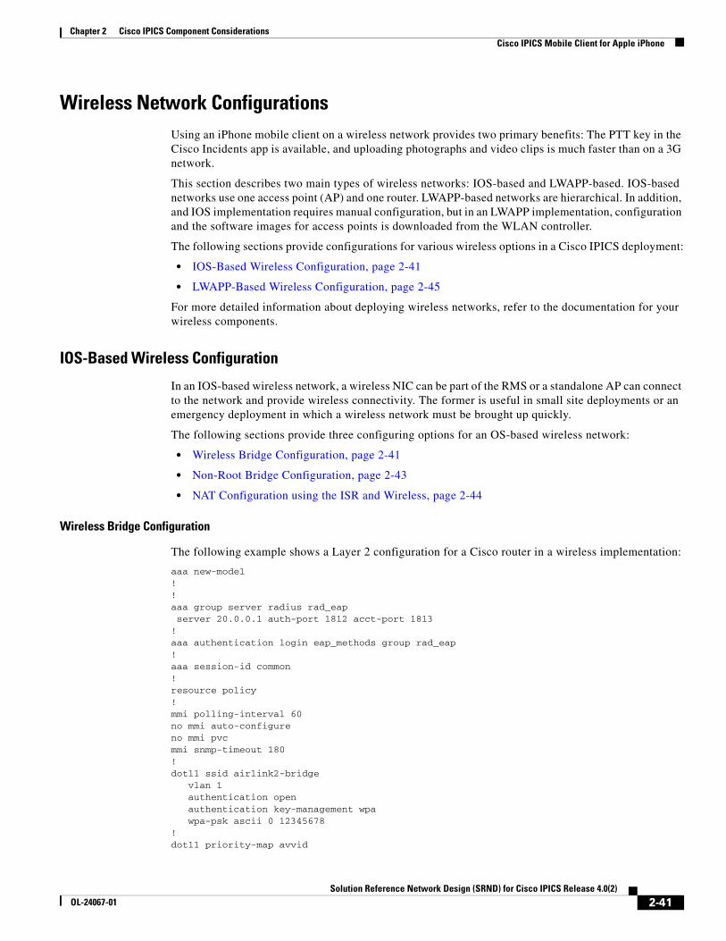
Chapter 2 Cisco IPICS Component ConsiderationsCisco IPICS Mobile Client for Apple iPhone
Wireless Network ConfigurationsUsing an iPhone mobile client on a wireless network provides two primary benefits: The PTT key in the Cisco Incidents app is available, and uploading photographs and video clips is much faster than on a 3G network.
This section describes two main types of wireless networks: IOS-based and LWAPP-based. IOS-based networks use one access point (AP) and one router. LWAPP-based networks are hierarchical. In addition, and IOS implementation requires manual configuration, but in an LWAPP implementation, configuration and the software images for access points is downloaded from the WLAN controller.
The following sections provide configurations for various wireless options in a Cisco IPICS deployment:
• IOS-Based Wireless Configuration, page 2-41
• LWAPP-Based Wireless Configuration, page 2-45
For more detailed information about deploying wireless networks, refer to the documentation for your wireless components.
IOS-Based Wireless Configuration
In an IOS-based wireless network, a wireless NIC can be part of the RMS or a standalone AP can connect to the network and provide wireless connectivity. The former is useful in small site deployments or an emergency deployment in which a wireless network must be brought up quickly.
The following sections provide three configuring options for an OS-based wireless network:
• Wireless Bridge Configuration, page 2-41
• Non-Root Bridge Configuration, page 2-43
• NAT Configuration using the ISR and Wireless, page 2-44
Wireless Bridge Configuration
The following example shows a Layer 2 configuration for a Cisco router in a wireless implementation:
aaa new-model!!aaa group server radius rad_eap server 20.0.0.1 auth-port 1812 acct-port 1813!aaa authentication login eap_methods group rad_eap!aaa session-id common!resource policy!mmi polling-interval 60no mmi auto-configureno mmi pvcmmi snmp-timeout 180!dot11 ssid airlink2-bridge vlan 1 authentication open authentication key-management wpa wpa-psk ascii 0 12345678!dot11 priority-map avvid
2-41Solution Reference Network Design (SRND) for Cisco IPICS Release 4.0(2)
OL-24067-01

Chapter 2 Cisco IPICS Component ConsiderationsCisco IPICS Mobile Client for Apple iPhone
ip cef!!no ip domain lookup!!bridge irb!!interface FastEthernet0/0 no ip address shutdown duplex auto speed auto!interface FastEthernet0/1 ip address 30.0.0.1 255.0.0.0 duplex auto speed auto!interface Dot11Radio0/0/0 no ip address ! encryption vlan 1 mode ciphers tkip ! ssid airlink2-bridge ! speed basic-1.0 basic-2.0 basic-5.5 6.0 9.0 basic-11.0 12.0 18.0 24.0 36.0 48.0 54.0 station-role root bridge!interface Dot11Radio0/0/0.1 encapsulation dot1Q 1 native no snmp trap link-status bridge-group 1 bridge-group 1 spanning-disabled!interface Dot11Radio0/0/1 no ip address speed basic-6.0 9.0 basic-12.0 18.0 basic-24.0 36.0 48.0 54.0 station-role root!interface BVI1 ip address 20.0.0.1 255.0.0.0!ip route 0.0.0.0 0.0.0.0 20.0.0.5! !ip http serverno ip http secure-server!!radius-server local nas 20.0.0.1 key 0 wireless user non-root nthash 0 3741A4EE66E1AA56CD8B3A9038580DC9!radius-server host 20.0.0.1 auth-port 1812 acct-port 1813 key wireless!control-plane!bridge 1 route ip!!line con 0 exec-timeout 0 0
2-42Solution Reference Network Design (SRND) for Cisco IPICS Release 4.0(2)
OL-24067-01
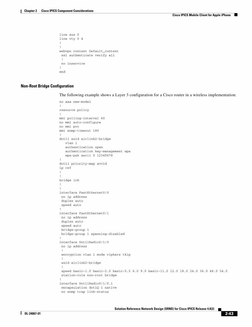
Chapter 2 Cisco IPICS Component ConsiderationsCisco IPICS Mobile Client for Apple iPhone
line aux 0line vty 0 4!!webvpn context Default_context ssl authenticate verify all ! no inservice!end
Non-Root Bridge Configuration
The following example shows a Layer 3 configuration for a Cisco router in a wireless implementation:
no aaa new-model!resource policy!mmi polling-interval 60no mmi auto-configureno mmi pvcmmi snmp-timeout 180! dot11 ssid airlink2-bridge vlan 1 authentication open authentication key-management wpa wpa-psk ascii 0 12345678!dot11 priority-map avvidip cef!!bridge irb!!interface FastEthernet0/0 no ip address duplex auto speed auto!interface FastEthernet0/1 no ip address duplex auto speed auto bridge-group 1 bridge-group 1 spanning-disabled!interface Dot11Radio0/1/0 no ip address ! encryption vlan 1 mode ciphers tkip ! ssid airlink2-bridge ! speed basic-1.0 basic-2.0 basic-5.5 6.0 9.0 basic-11.0 12.0 18.0 24.0 36.0 48.0 54.0 station-role non-root bridge!interface Dot11Radio0/1/0.1 encapsulation dot1Q 1 native no snmp trap link-status
2-43Solution Reference Network Design (SRND) for Cisco IPICS Release 4.0(2)
OL-24067-01
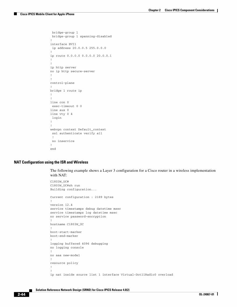
Chapter 2 Cisco IPICS Component ConsiderationsCisco IPICS Mobile Client for Apple iPhone
bridge-group 1 bridge-group 1 spanning-disabled!interface BVI1 ip address 20.0.0.5 255.0.0.0!ip route 0.0.0.0 0.0.0.0 20.0.0.1!!ip http serverno ip http secure-server!!control-plane!bridge 1 route ip!!line con 0 exec-timeout 0 0line aux 0line vty 0 4 login!!webvpn context Default_context ssl authenticate verify all ! no inservice!end
NAT Configuration using the ISR and Wireless
The following example shows a Layer 3 configuration for a Cisco router in a wireless implementation with NAT:
C1803W_UC#C1803W_UC#sh runBuilding configuration...
Current configuration : 2189 bytes!version 12.4service timestamps debug datetime msecservice timestamps log datetime msecno service password-encryption!hostname C1803W_UC!boot-start-markerboot-end-marker!logging buffered 4096 debuggingno logging console!no aaa new-model!resource policy!!ip nat inside source list 1 interface Virtual-Dot11Radio0 overload
2-44Solution Reference Network Design (SRND) for Cisco IPICS Release 4.0(2)
OL-24067-01
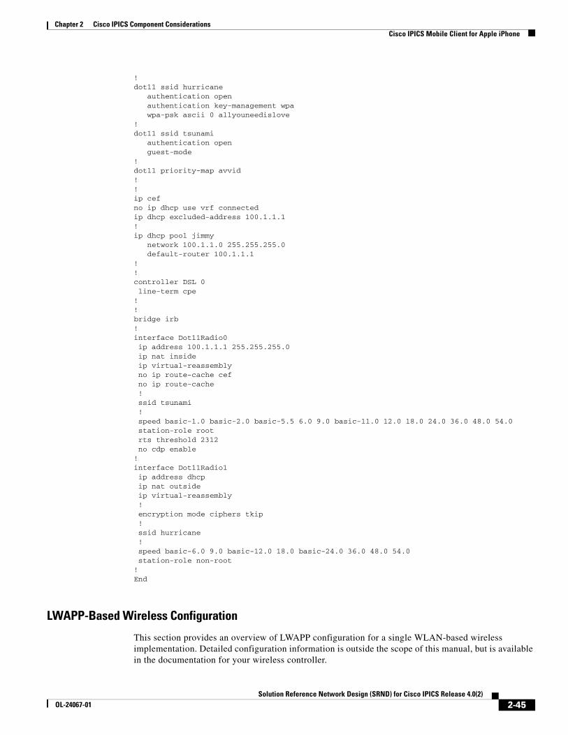
Chapter 2 Cisco IPICS Component ConsiderationsCisco IPICS Mobile Client for Apple iPhone
!dot11 ssid hurricane authentication open authentication key-management wpa wpa-psk ascii 0 allyouneedislove! dot11 ssid tsunami authentication open guest-mode! dot11 priority-map avvid! ! ip cef no ip dhcp use vrf connectedip dhcp excluded-address 100.1.1.1! ip dhcp pool jimmy network 100.1.1.0 255.255.255.0 default-router 100.1.1.1 !!controller DSL 0 line-term cpe! !bridge irb! interface Dot11Radio0 ip address 100.1.1.1 255.255.255.0 ip nat inside ip virtual-reassembly no ip route-cache cef no ip route-cache ! ssid tsunami ! speed basic-1.0 basic-2.0 basic-5.5 6.0 9.0 basic-11.0 12.0 18.0 24.0 36.0 48.0 54.0 station-role root rts threshold 2312 no cdp enable!interface Dot11Radio1 ip address dhcp ip nat outside ip virtual-reassembly ! encryption mode ciphers tkip ! ssid hurricane ! speed basic-6.0 9.0 basic-12.0 18.0 basic-24.0 36.0 48.0 54.0 station-role non-root!End
LWAPP-Based Wireless Configuration
This section provides an overview of LWAPP configuration for a single WLAN-based wireless implementation. Detailed configuration information is outside the scope of this manual, but is available in the documentation for your wireless controller.
2-45Solution Reference Network Design (SRND) for Cisco IPICS Release 4.0(2)
OL-24067-01
Chapter 2 Cisco IPICS Component ConsiderationsCisco IPICS Mobile Client for Apple iPhone
A typical LWAPP-based wireless network requires at least two pieces of hardware: the WLAN controller and the an LWAPP-based access point. The information in this section assumes that an Ethernet network is in place and that the WLAN controller and the LWAPP-based access can reach each other
On the LWAPP controller, you must configure the Management Interface, AP-Manager, and WLAN SSID with the appropriate security settings. Optionally, the DHCP server and the VPN passthrough also can be configured on the WLAN controller to provide a richer and more integrated user experience to iPhone users. The DNS server cannot be configured on the WLAN controller and must be configured separately.
Configuring the Management Interface and AP-Manager is straightforward: you must assign an IP address assigned to each of these interfaces. The Management Interface is used by a system administrator to access the WLAN controller. The AP-Manager is used by access points to reach the WLAN controller and download their configurations.
Configuring the SSID requires the name of the SSID and the radio policy that is associated with the SSID. In addition, broadcast SSID should be enabled. Authentication is optional but recommended.
Note If you do not enable the broadcast SSID on the WLAN, you must configure the WLAN on an iPhone each time you access the Incident application. This approach is not recommended. It is best to broadcast the SSID and enable some level of encryption on the Wireless connectivity that is shared between he iPhone and the WLAN controller.
If your deployment includes a standalone DHCP server that allocates IP addresses mobile clients, ensure that you configure Override for the DCHP server in the SSID configuration pages and specify the IP address of this DHCP server.
The WLAN controller includes a built-in DHCP server that also can be enabled to provide IP addresses for mobile clients. However, this DHCP server has limited functionality and is not recommended for a large enterprise with many clients that require specialized DHCP configuration.
Wireless Configuration on an iPhoneAfter the configuration of the wireless infrastructure is complete, it is a relatively simple process to configure a iPhone for wireless connectivity. This section describes how to configure an iPhone for connectivity to the Cisco IPICS server over a wireless network. After For additional information about wireless connectivity for an iPhone, see your iPhone documentation and online forums.
To configure wireless on an iPhone, follow these steps:
Procedure
Step 1 On the iPhone, launch the Settings app.
Step 2 Touch Wi-Fi settings icon, then choose the WLAN ID that you configured from the list of IDs.
Step 3 If security is enabled for your wireless network, enter the security passphrase.
The iPhone automatically determines the encryption method to use to connect to the WLAN controller. In some situations, it might be necessary to enter the security information manually on the iPhone.
2-46Solution Reference Network Design (SRND) for Cisco IPICS Release 4.0(2)
OL-24067-01
Chapter 2 Cisco IPICS Component ConsiderationsCisco Unified IP Phones
Cisco Unified IP PhonesIf your Cisco IPICS deployment includes Cisco Unified Communications Manager or Cisco Unified Communications Manager Express, you can use the Cisco Unified IP Phone services application programming interface (API) to provide PTT capabilities to certain Cisco Unified IP Phone models. A phone with the PTT capability enabled can function similarly to an IDC, providing an easy-to-use GUI that allows users to monitor or participate in a PTT channels or VTG over a VoIP network. However, unlike an IDC, a phone can participate in only one channel or VTG at a time. To participate in a channel or VTG, a phone user chooses the desired channel or VTG from a list that displays on the phone.
A phone that is configured to work as a PTT device uses a stand-alone LMR PTT audio client. This Extensible Markup Language (XML) application enables the display of interactive content with text and graphics on the phone.
To enable this feature, Cisco Unified Communications Manager or Cisco Unified Communications Manager Express must be deployed in your IP telephony (IPT) network, and either of these applications must be configured with the IP address of the Cisco IPICS server. A Cisco Unified IP Phone uses this IP address to locate the server and download the PTT XML application.
For related information about configuring this feature, refer to the “Setting Up the Cisco IP Phone for use with Cisco IPICS” appendix in Cisco IPICS Server Administration Guide, Release 4.0(2). For a list of Cisco Unified IP Phones that Cisco IPICS supports as PTT devices, refer to Cisco IPICS Compatibility Matrix.
This section includes these topics:
• Cisco Unified Communications Manager Configuration Overview, page 2-47
• Cisco Unified Communications Manager Express Configuration Overview, page 2-47
Cisco Unified Communications Manager Configuration OverviewYou use the Cisco IP Phone Services Configuration page in the Cisco Unified Communications Manager Administration application to define and maintain the list of Cisco Unified IP Phone services to which users can subscribe. These services are XML applications that enable the display of interactive content on supported models of a Cisco Unified IP Phone.
After you configure a list of IP phone services, Cisco Unified IP Phone users can access the Cisco Unified Communications Manager User Options menu and subscribe to the services, or an administrator can add services to Cisco Unified IP Phones and device profiles. Administrators can assign services to speed-dial buttons, so users have one-button access to the services.
For detailed information about configuring phone services, refer to the “Cisco IP Phone Services” chapter in Cisco Unified Communications Manager System Guide, which is available at this URL:
http://www.cisco.com/en/US/products/sw/voicesw/ps556/tsd_products_support_series_home.html
Cisco Unified Communications Manager Express Configuration OverviewThe following is a sample Cisco IOS router configuration that enables Cisco Unified Communications Manager Express to support a Cisco Unified IP Phone as a Cisco IPICS PTT device:
ip dhcp excluded-address 10.1.1.1!ip dhcp pool pool1 network 10.1.1.0 255.255.255.248 domain-name yourdomainname
2-47Solution Reference Network Design (SRND) for Cisco IPICS Release 4.0(2)
OL-24067-01
Chapter 2 Cisco IPICS Component ConsiderationsText to Speech
dns-server dns1 dns2 default-router 10.1.1.1 option 150 ip 10.1.1.1
tftp-server flash:filename1tftp-server flash:filename2
telephony-service load 7960-7940 filename1 load 7970 filename2 max-ephones n max-dn m ip source-address 10.1.1.1 port 2000 auto assign 1 to n url services http://10.1.2.1/ipics_server/servlet/IPPhoneManager create cnf-files max-conferences 8 gain -6
ephone-dn 1 dual-line number abcd!ephone-dn 2 dual-line number efgh
Text to SpeechCisco IPICS provides an interface to the Nuance text to speech (TTS) server, which is available from Nuance. This interface uses Media Resource Control Protocol (MRCP) to enable the Cisco IPICS dial engine to pass text strings to the TTS server, which in turn converts the text to audio. The dial engine then play the TTS audio to connected devices. This feature enables a more dynamic notification environment than is possible by prerecorded audio prompts.
Cisco IPICS uses the following rules to determine how to play prompts:
1. If a recorded prompt .wav file exists, it is played.
2. If no recorded prompt exists and a TTS provider is configured and accessible, TTS is used.
3. If no recorded prompt or TTS provider are available, the text is spelled out as the prompt. For example, if the name of a channel is “chan1” but there is no recorded prompt or TTS provider, Cisco IPICS might play this prompt: “Press 1 to select C H A N one.”
These rules apply to the standard Cisco IPICS capabilities for announcing resource names during dial-in or dial-out call scenarios.
In addition, you can deploy custom scripts to use TTS prompts in a wide variety of scenarios. Custom scripts are available through Cisco Advanced Services.
The following sections provide additional information about TTS:
• Installing Nuance TTS, page 2-49
• Configuring a Language Pack Other than en-US, page 2-50
• TTS Configuration and Operation, page 2-51
2-48Solution Reference Network Design (SRND) for Cisco IPICS Release 4.0(2)
OL-24067-01
Chapter 2 Cisco IPICS Component ConsiderationsText to Speech
Installing Nuance TTSCisco IPICS operates with a dedicated TTS server that runs on a Microsoft Windows platform. This section describes how to install Nuance TTS (no ASR) and assume that the Cisco IPICS software is already installed on the Cisco IPICS server.
Installation of Cisco IPICS is not required to install Nuance TTS.
Note The default Nuance TTS installation contains licenses for TTS ports. If you need more licenses, obtain them from your Nuance TTS vendor.
To install the Nuance TTS software, perform the following procedure on the dedicated TTS server. All Nuance TTS components are available from Nuance.
Procedure
Step 1 If there is Nuance software already installed on the server, take these actions:
a. Uninstall the Nuance software.
b. Delete the following directories, if they exist:
c. C:/Nuance
d. C:/Program Files/Nuance
e. Reboot the server.
Step 2 Follow the instructions that are provided with your Nuance software to install Nuance MRCP.
This process installs all Nuance TTS components except Vocalizer (TTS).
Step 3 Follow the instructions that are provided with your Nuance software to install the Nuance Vocalizer TTS software.
Step 4 Follow the instructions that are provided with your Nuance software to install the English language pack for TTS.
Step 5 Take these actions to configure TTS for use with Cisco IPICS.
a. Modify the watcher.startup file in the C:\Nuance\V8.5.0\mrcp to add the tts.ResourceName parameter for the vocalizer process.
For example, modify the existing line for Vocalizer from:
vocalizer -text_type SSML -config %MRCP%/nuance-resources.txt lm.Addresses=localhost:8471
to:
vocalizer -text_type SSML tts.ResourceName=en-US-female -config %MRCP%/nuance-resources.txt lm.Addresses=localhost:8471
b. If you are using TTS in high load scenarios, make these modifications to the watcher.startup file:
– Use the num_channels parameter to allow for the maximum number of TTS ports that you are provisioning for.
– Use the preallocate_licenses parameter to improve response time.
– Use the load_voices_in_memory parameter to load the complete voice pack in memory. Note: This configuration increases process memory and initialization time.
2-49Solution Reference Network Design (SRND) for Cisco IPICS Release 4.0(2)
OL-24067-01
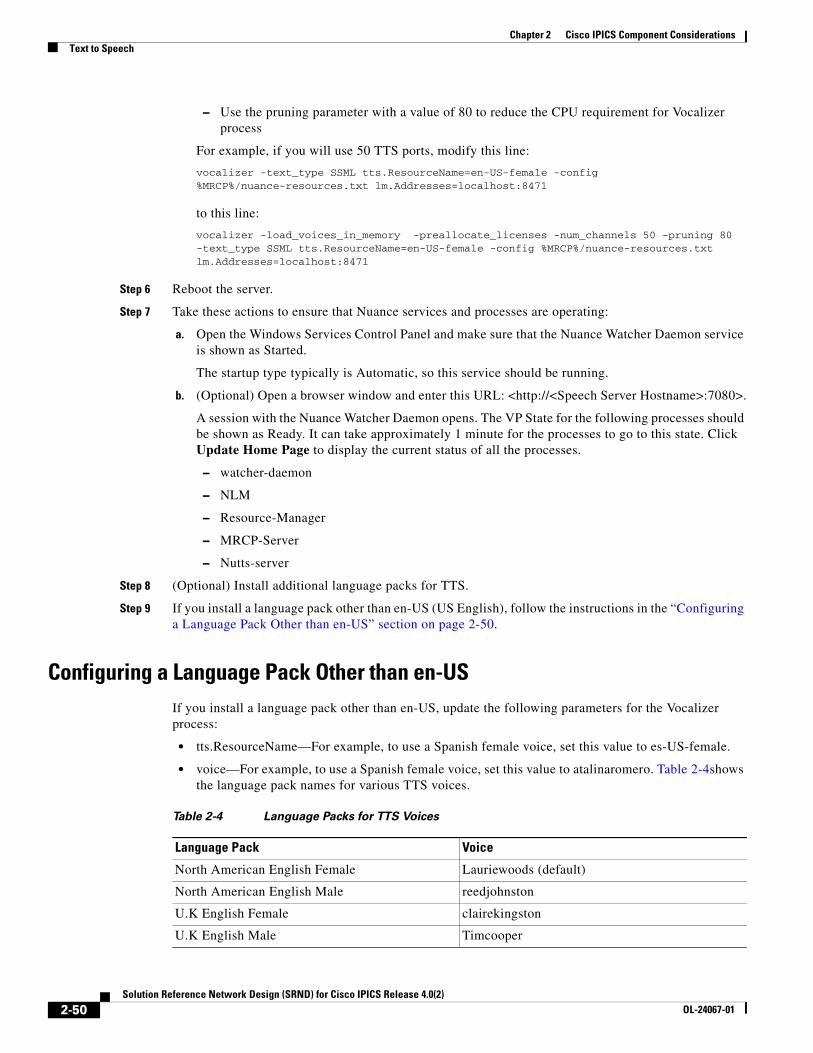
Chapter 2 Cisco IPICS Component ConsiderationsText to Speech
– Use the pruning parameter with a value of 80 to reduce the CPU requirement for Vocalizer process
For example, if you will use 50 TTS ports, modify this line:
vocalizer -text_type SSML tts.ResourceName=en-US-female -config %MRCP%/nuance-resources.txt lm.Addresses=localhost:8471
to this line:
vocalizer -load_voices_in_memory -preallocate_licenses -num_channels 50 -pruning 80 -text_type SSML tts.ResourceName=en-US-female -config %MRCP%/nuance-resources.txt lm.Addresses=localhost:8471
Step 6 Reboot the server.
Step 7 Take these actions to ensure that Nuance services and processes are operating:
a. Open the Windows Services Control Panel and make sure that the Nuance Watcher Daemon service is shown as Started.
The startup type typically is Automatic, so this service should be running.
b. (Optional) Open a browser window and enter this URL: <http://<Speech Server Hostname>:7080>.
A session with the Nuance Watcher Daemon opens. The VP State for the following processes should be shown as Ready. It can take approximately 1 minute for the processes to go to this state. Click Update Home Page to display the current status of all the processes.
– watcher-daemon
– NLM
– Resource-Manager
– MRCP-Server
– Nutts-server
Step 8 (Optional) Install additional language packs for TTS.
Step 9 If you install a language pack other than en-US (US English), follow the instructions in the “Configuring a Language Pack Other than en-US” section on page 2-50.
Configuring a Language Pack Other than en-USIf you install a language pack other than en-US, update the following parameters for the Vocalizer process:
• tts.ResourceName—For example, to use a Spanish female voice, set this value to es-US-female.
• voice—For example, to use a Spanish female voice, set this value to atalinaromero. Table 2-4shows the language pack names for various TTS voices.
Table 2-4 Language Packs for TTS Voices
Language Pack Voice
North American English Female Lauriewoods (default)
North American English Male reedjohnston
U.K English Female clairekingston
U.K English Male Timcooper
2-50Solution Reference Network Design (SRND) for Cisco IPICS Release 4.0(2)
OL-24067-01
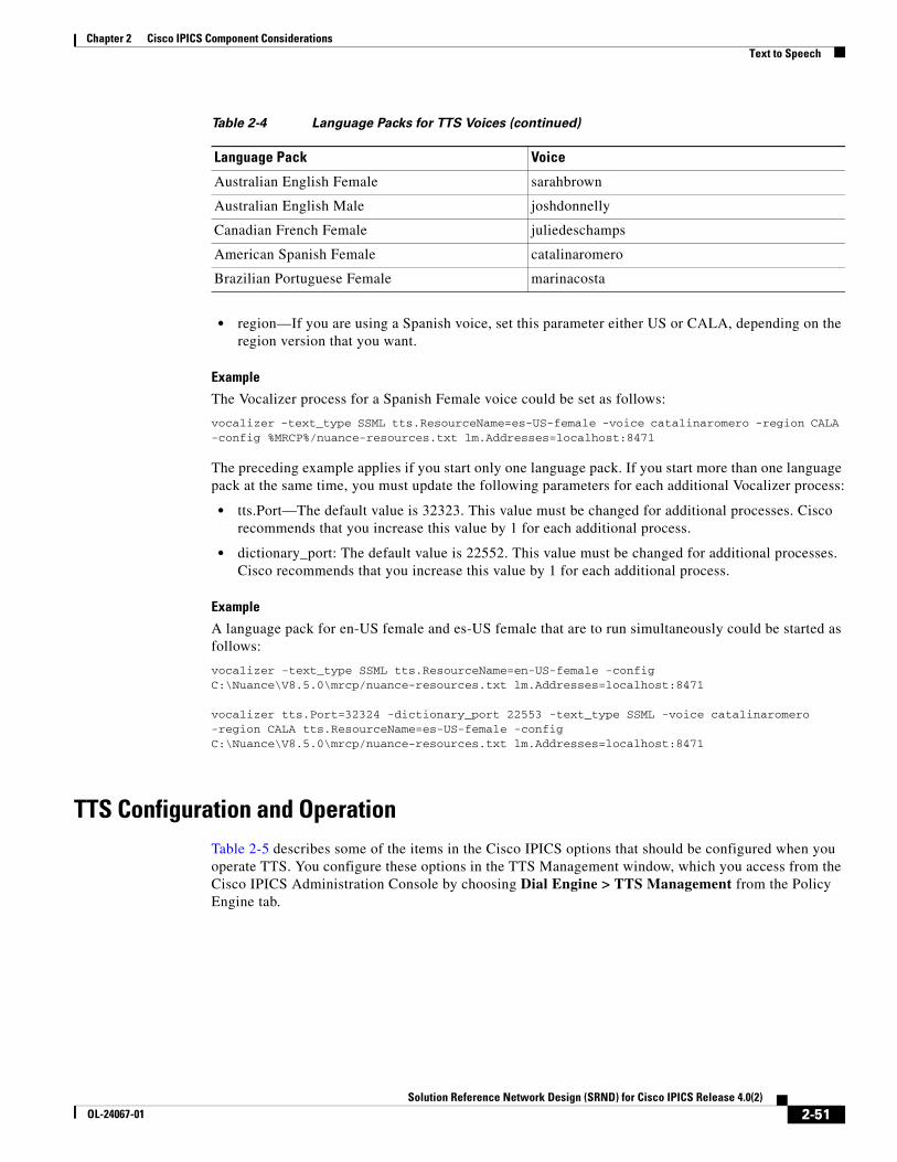
Chapter 2 Cisco IPICS Component ConsiderationsText to Speech
• region—If you are using a Spanish voice, set this parameter either US or CALA, depending on the region version that you want.
Example
The Vocalizer process for a Spanish Female voice could be set as follows:
vocalizer -text_type SSML tts.ResourceName=es-US-female -voice catalinaromero -region CALA -config %MRCP%/nuance-resources.txt lm.Addresses=localhost:8471
The preceding example applies if you start only one language pack. If you start more than one language pack at the same time, you must update the following parameters for each additional Vocalizer process:
• tts.Port—The default value is 32323. This value must be changed for additional processes. Cisco recommends that you increase this value by 1 for each additional process.
• dictionary_port: The default value is 22552. This value must be changed for additional processes. Cisco recommends that you increase this value by 1 for each additional process.
Example
A language pack for en-US female and es-US female that are to run simultaneously could be started as follows:
vocalizer -text_type SSML tts.ResourceName=en-US-female -config C:\Nuance\V8.5.0\mrcp/nuance-resources.txt lm.Addresses=localhost:8471
vocalizer tts.Port=32324 -dictionary_port 22553 -text_type SSML -voice catalinaromero -region CALA tts.ResourceName=es-US-female -config C:\Nuance\V8.5.0\mrcp/nuance-resources.txt lm.Addresses=localhost:8471
TTS Configuration and OperationTable 2-5 describes some of the items in the Cisco IPICS options that should be configured when you operate TTS. You configure these options in the TTS Management window, which you access from the Cisco IPICS Administration Console by choosing Dial Engine > TTS Management from the Policy Engine tab.
Australian English Female sarahbrown
Australian English Male joshdonnelly
Canadian French Female juliedeschamps
American Spanish Female catalinaromero
Brazilian Portuguese Female marinacosta
Table 2-4 Language Packs for TTS Voices (continued)
Language Pack Voice
2-51Solution Reference Network Design (SRND) for Cisco IPICS Release 4.0(2)
OL-24067-01
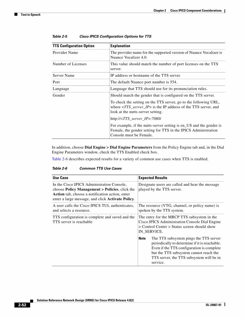
Chapter 2 Cisco IPICS Component ConsiderationsText to Speech
In addition, choose Dial Engine > Dial Engine Parameters from the Policy Engine tab and, in the Dial Engine Parameters window, check the TTS Enabled check box.
Table 2-6 describes expected results for a variety of common use cases when TTS is enabled.
Table 2-5 Cisco IPICS Configuration Options for TTS
TTS Configuration Option Explanation
Provider Name The provider name for the supported version of Nuance Vocalizer is Nuance Vocalizer 4.0.
Number of Licenses This value should match the number of port licenses on the TTS server.
Server Name IP address or hostname of the TTS server.
Port The default Nuance port number is 554.
Language Language that TTS should use for its pronunciation rules.
Gender Should match the gender that is configured on the TTS server.
To check the setting on the TTS server, go to the following URL, where <TTS_server_IP> is the IP address of the TTS server, and look at the nutts-server setting.
http://<TTS_server_IP>:7080/
For example, if the nutts-server setting is en_US and the gender is Female, the gender setting for TTS in the IPICS Administration Console must be Female.
Table 2-6 Common TTS Use Cases
Use Case Expected Results
In the Cisco IPICS Administration Console, choose Policy Management > Policies, click the Action tab, choose a notification action, enter enter a large message, and click Activate Policy.
Designate users are called and hear the message played by the TTS server.
A user calls the Cisco IPICS TUI, authenticates, and selects a resource.
The resource (VTG, channel, or policy name) is spoken by the TTS system.
TTS configuration is complete and saved and the TTS server is reachable
The entry for the MRCP TTS subsystem in the Cisco IPICS Administration Console Dial Engine > Control Center > Status screen should show IN_SERVICE.
Note The TTS subsystem pings the TTS server periodically to determine if it is reachable. Even if the TTS configuration is complete but the TTS subsystem cannot reach the TTS server, the TTS subsystem will be in service.
2-52Solution Reference Network Design (SRND) for Cisco IPICS Release 4.0(2)
OL-24067-01
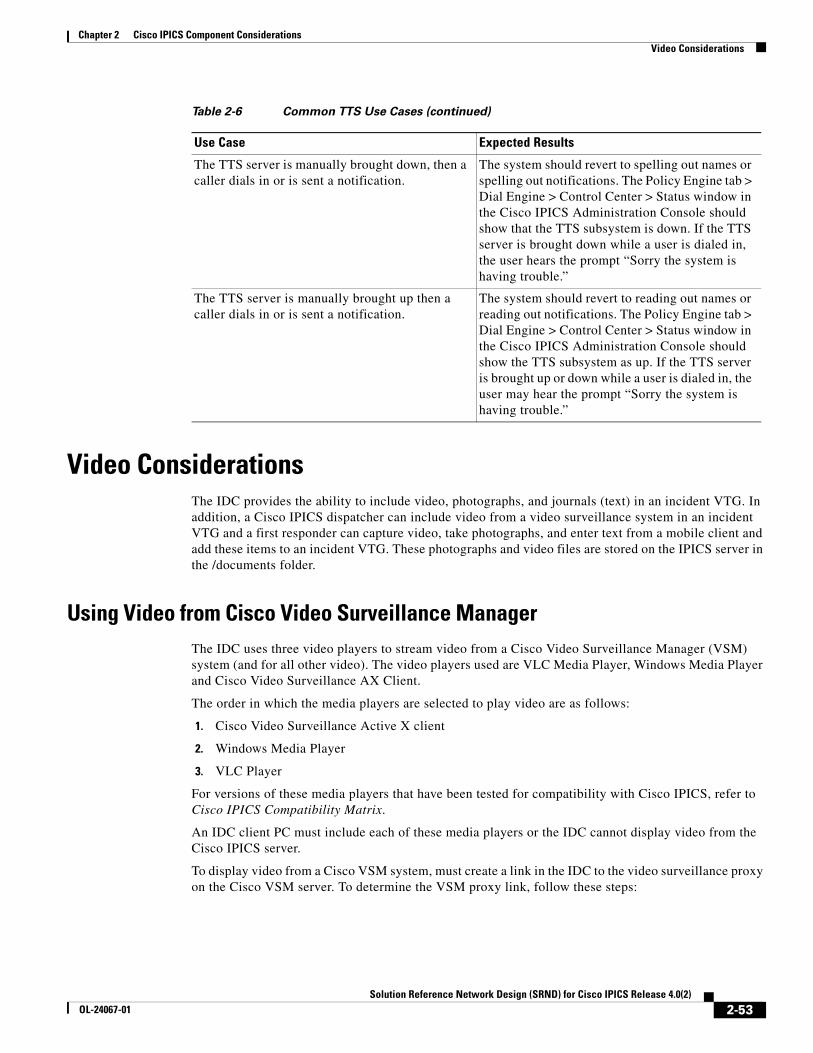
Chapter 2 Cisco IPICS Component ConsiderationsVideo Considerations
Video ConsiderationsThe IDC provides the ability to include video, photographs, and journals (text) in an incident VTG. In addition, a Cisco IPICS dispatcher can include video from a video surveillance system in an incident VTG and a first responder can capture video, take photographs, and enter text from a mobile client and add these items to an incident VTG. These photographs and video files are stored on the IPICS server in the /documents folder.
Using Video from Cisco Video Surveillance ManagerThe IDC uses three video players to stream video from a Cisco Video Surveillance Manager (VSM) system (and for all other video). The video players used are VLC Media Player, Windows Media Player and Cisco Video Surveillance AX Client.
The order in which the media players are selected to play video are as follows:
1. Cisco Video Surveillance Active X client
2. Windows Media Player
3. VLC Player
For versions of these media players that have been tested for compatibility with Cisco IPICS, refer to Cisco IPICS Compatibility Matrix.
An IDC client PC must include each of these media players or the IDC cannot display video from the Cisco IPICS server.
To display video from a Cisco VSM system, must create a link in the IDC to the video surveillance proxy on the Cisco VSM server. To determine the VSM proxy link, follow these steps:
The TTS server is manually brought down, then a caller dials in or is sent a notification.
The system should revert to spelling out names or spelling out notifications. The Policy Engine tab > Dial Engine > Control Center > Status window in the Cisco IPICS Administration Console should show that the TTS subsystem is down. If the TTS server is brought down while a user is dialed in, the user hears the prompt “Sorry the system is having trouble.”
The TTS server is manually brought up then a caller dials in or is sent a notification.
The system should revert to reading out names or reading out notifications. The Policy Engine tab > Dial Engine > Control Center > Status window in the Cisco IPICS Administration Console should show the TTS subsystem as up. If the TTS server is brought up or down while a user is dialed in, the user may hear the prompt “Sorry the system is having trouble.”
Table 2-6 Common TTS Use Cases (continued)
Use Case Expected Results
2-53Solution Reference Network Design (SRND) for Cisco IPICS Release 4.0(2)
OL-24067-01
Chapter 2 Cisco IPICS Component ConsiderationsVideo Considerations
Procedure
Step 1 Access the VSM Management Console for VSMS host that manages the cameras that provides the video that you want, and take the following actions.
For information about accessing the Management Console, see the “Using the VSM Management Console” chapter in Cisco Video Surveillance Manager User Guide.
Step 2 Click BWT Pages under Other Utilities near the bottom of the left panel in the Management Console page.
Step 3 Click Proxy Commands in the left panel of the page that appears.
A list of proxy commands appears.
Step 4 Click All Running Proxies in the list of proxy commands.
A table of running proxies appears.
Step 5 Make a note of the proxy name for the camera feed that you want to include in the incident VTG.
Step 6 (Optional) Exit the Management Console.
After you determine the VSM proxy link, start the IDC, choose the incident VTG in which you want to include the video, select the option to add media, and enter video using the proxy name that you determined in the previous procedure.
After the proxy information in entered into an incident VTG, this can be enabled and disabled as needed. It also can be used in other incident VTGs.
For information about using incident VTGs, refer to Cisco IPICS Dispatch Console User Guide.
Guidelines for VideoWhen including video in an incident, be aware of the following guidelines:
• If you use a URL for a video that starts with bwims://, the ActiveX player from the VSM server is used to play the video on the IDC. The iPhone cannot play this video because it cannot interpret the URL.
• To view video on an iPhone, use an MJPEG video URL that starts with http://.
• The IDC supports any video format that Windows Media Player and VLC Player support. For limitations of various protocols, refer to Cisco IPICS Dispatch Console User Guide.
• If want to stream video from Cisco VSM to an iPhone, you must use the secondary stream when configuring the video stream in VSM. (For instructions, refer to Cisco Video Surveillance Manager User Guide.) After you configure a secondary stream in VSM, all the secondary streaming video appears with a “_2” at the end of the proxy when you display proxies as described in the “Using Video from Cisco Video Surveillance Manager” section on page 2-53. When adding video in the IDC that is intended to display on an iPhone, it is a best practice to give the video a name that clearly indicates that the stream is meant for viewing on an iPhone.
2-54Solution Reference Network Design (SRND) for Cisco IPICS Release 4.0(2)
OL-24067-01
Chapter 2 Cisco IPICS Component ConsiderationsNotification
• The follow video streaming configuration is supported on an iPhone:
– Protocol—MJPEG
– Resolution—CIF (352 × 288)
– Frame rate—Up to 5 fps
– Streaming—Suggested Up to 10 minutes continuous
If you exceed these rates or use a different protocol, the mobile client displays a question mark (?) in the area where you expect the video to appear. The video displays on the IDC if the media players can support those formats.
• In Cisco IPICS 4.0.1, the maximum size of media files that can be uploaded to the IPICS Server by using the IDC is 4 MB. In Cisco IPICS 4.0.2, the maximum size of media files is configurable up to 2,048 MB (the default value is 4 MB).
• There are no restrictions on the URL that can be attached to an incident. The Cisco IPICS server does not verify the URL and every URL that is entered is considered valid. Take care to ensure accuracy when entering a URL.
• When high availability (HA) is implemented in a Cisco IPICS deployment, media files that are stored on the active service must be synchronized with the standby server. As a best practice in an HA implementation, create and use URL links to the proxy from a Cisco CSM system whenever possible instead of uploading video files of different formats. This approach helps conserve bandwidth on the network between the active and standby servers. It also helps conserve storage space on the Cisco IPICS server.
NotificationNotification is the process of Cisco IPICS contacting designated recipients and provide them with information that you specify. Cisco IPICS offers the following notification implementations:
• Policy engine notification—Controlled through the Cisco IPICS Administration Console and can provide notification to recipients that are configured in Cisco IPICS. You designate the way in which notification is provided by configuring notification actions. Policy engine notifications include e-mail, IP phone text, dial, talk group, and dial engine script notifications.
• External (Bulk) notification—Administered outside of the Cisco IPICS Administration Console. The recipient list and prompts are passed to Cisco IPICS by a third-party application.
Cisco IPICS supports multiple Cisco Unified Communications Managers for notification, which enables text and audio paging to Cisco Unified IP Phone devices that are registered on different Cisco Unified Communications Managers.
The following sections describe following policy engine notification actions that you can configure for Cisco IPICS:
• Email Notification Action, page 2-56
• IP Phone Text Notification Action, page 2-56
• Dial Notification Action, page 2-57
• Talk Group Notification Action, page 2-57
• Dial Engine Script Notification, page 2-58
• Alert Notification Action, page 2-58
• External (Bulk) Notification, page 2-58
2-55Solution Reference Network Design (SRND) for Cisco IPICS Release 4.0(2)
OL-24067-01
Chapter 2 Cisco IPICS Component ConsiderationsNotification
Email Notification ActionAn Email notification action sends a message that you enter to the e-mail, SMS, and pager addresses that are configured as notification preferences for each user that you designate as a recipient. When this type of notification executes, the policy engine sends the message via SMTP to the SMTP server that is configured on the IPICS Dial Engine Parameters screen. Email notification recipients can be Cisco IPICS users or user groups.
IP Phone Text Notification Action An IP phone text notification action displays a designated message on supported Cisco Unified IP Phone models. The telephone numbers of each phone must be configured as a dial preference for the associated user. This type of notification action requires that you use the Cisco IPICS Administration Console to configure parameters in the Cisco Unified Communications Manager Configuration for IP Phone Notifications area in the SIP Configuration menu. For instructions, see Cisco IPICS Server Administration Guide. Recipients of this notification action can be Cisco IPICS users or user groups.
When an IP phone text notification action executes, several activities, including the following, occur:
1. IPICS sends an AXL query to the first configured Cisco Unified Communications Manager.
2. Cisco Unified Communications Manager returns the IP address of each device for which a DN is configured.
3. Cisco IPICS sends notification via XML to each device for which it receives a valid IP address.
Notes:
• The IP phone text notification action requires that the IP phone text notification parameters be configured on the SIP configuration page in the Cisco IPICS Administration Console.
• Cisco IPICS sends each DN in the notification list as a query to each Cisco Unified Communications Manager that is configured for notification.
• The Cisco Unified Communications Manager must be running the Cisco AXL service.
• Each Cisco Unified Communications Manager must be configured in the IP Phone Notification Configuration page with the correct version number, administrator and phone user name and password. This information is required validate Cisco Unified Communications Manager and send appropriate AXL queries because the queries are different for various Cisco Unified Communications Manager versions.
• The configured Cisco Unified Communications Managers must be reachable or “Connection Failure” errors result when the Cisco IPICS attempts to send and AXL query.
• The Cisco Unified Communications Manager should be configured to accept SOAP requests.
• Cisco Unified Communications Manager limits the number of DNs in an AXL query to 200. It truncates requests that contain more than 200 DNs. To accommodate this limit, Cisco IPICS sends requests that contain no more than 200 DNs. If Cisco IPICS needs more than 200 DNs, it send requests in batches that contain 200 or fewer DN requests.
• Cisco IPICS precedes a text notification with an audible tone, which comes from a prerecorded .wav file that is sent to each phone in the recipient list. Cisco IPICS requires that an available multicast address be configure in the multicast address pool for each batch of simultaneous broadcasts of the alert audio.
2-56Solution Reference Network Design (SRND) for Cisco IPICS Release 4.0(2)
OL-24067-01
Chapter 2 Cisco IPICS Component ConsiderationsNotification
• If Cisco IPICS cannot reach a Cisco Unified IP Phone or if notification to a phone fails, Cisco IPICS adds the phone to a retry list. When Cisco IPICS completes a round of notification to identified phones, it attempts to resend the notification to the phones in the retry list. Cisco IPICS will attempt notification up to three times (one regular notification attempt and up to two retry notification attempts). Any phones that it cannot reach after these attempts are not notified via IP phone text notification.
• Cisco IPICS an AXL query to all Cisco Unified Communications Managers in a cluster. If more than one Cisco Unified Communications Manager is configured with phones that register to the same DN, all the phones associated to that DN are notified.
Dial Notification Action The policy engine executes a dial notification action as follows:
• If the Cisco Unified Communications Manager Configuration for IP Phone Notifications parameters are configured in the SIP Configuration menu, the Cisco IPICS checks whether each designated user has an associated Cisco Unified IP Phone configured in Cisco Unified Communications Manager. If a user does have an associated phone, Cisco IPICS plays the designated message on the speaker of the phone.
• If Cisco Unified Communications Manager Configuration for IP Phone Notifications parameters are configured but a user does not have an associated Cisco Unified IP Phone, or if the phone of a user is busy, the system calls the user as specified in the dial preferences and plays the designated message.
• If Cisco Unified Communications Manager Configuration for IP Phone Notifications parameters are not configured, the Cisco IPICS calls the user as specified in the dial preferences and plays the designated message.
When you create a dial notification action, you can specify a pre-recorded prompt or record a new prompt. A prompt should be no more than 90 seconds long.
If you use this action to contact Cisco Unified IP Phones, make sure that at least one multicast address is available in the multicast pool.
For more detailed information, see Cisco IPICS Server Administration Guide.
Talk Group Notification ActionA talk group notification action plays the selected prompt to all participants in the selected VTG.
When you create a talk group notification action, you can specify a pre-recorded prompt or record a new prompt. A prompt should be no more than 90 seconds long.
Note • When a Talk Group notification executes, the designated message is added to the multicast stream of the VTG. To inform users that a system message is being played, consider starting the message with a statement such as, “This is the Cisco IPICS administrator with an important recorded message.”
• A VTG participant who is dialed in through the TUI and who has the floor does not hear the talk group notification message.
2-57Solution Reference Network Design (SRND) for Cisco IPICS Release 4.0(2)
OL-24067-01
Chapter 2 Cisco IPICS Component ConsiderationsNotification
Dial Engine Script Notification A dial engine script notification action executes the designated dial engine script once for each designated recipient.
Alert Notification ActionAn alert notification action sends an alert message to the IDC and mobile client of each user who is associated with the policy and show has executed the policy from the IDC. The alert message appears in a pop-up window on the IDC and mobile client. A subsequent notification is not displayed until the existing notification is acknowledged.
External (Bulk) NotificationThis section provides notes that apply to external (bulk) notification. For more detailed information about this functionality, see Cisco IPICS Server Administration Guide.
• To debug the Bulk notification without pushing out the XML to the phones add the parameter “notificationMode=mute” to the external notification HTTP request.
• Cisco IPICS now periodically stores the results of calls that it makes when an external notification executes. These results are stored as XML files, which are purged after 30 days by default.
The purge time is based on a cron entry that is made for the ipicsadmin user. This cron entry purges all notification result XML files that are older than 30 days, by default. You can change the purge interval as follows:
#--- Purge notification result xml files older than 30 days daily @ 04:00
0 4 * * * find /opt/cisco/ippe/temp/notificationIncidentXmlResults/* -mtime +30 | xargs rm -fR 2>&1
• The stopNotification method can be used to terminate a running capId. Always verify that the capId status is not running before restarting a bulk notification request that uses the same CapId.
http://“ + ipicsServer + ”:8080/ipics_server/ BulkNotify?method=stopNotification&capId=<CAP_ID>
2-58Solution Reference Network Design (SRND) for Cisco IPICS Release 4.0(2)
OL-24067-01
Solution Reference NeOL-24067-01
C H A P T E R 3
Cisco IPICS LMR Gateway ConfigurationsThis chapter provides an overview of how to install and configure a land mobile radio (LMR) gateway to interface to audio devices. These audio devices typically consist of radios.
Cisco IPICS provides features that enable tone remote control of radios and other tone remote capable devices from an IDC. For detailed information about the tone remote functionality, refer to the “Performing Cisco IPICS System Administrator Tasks” chapter in Cisco IPICS Server Administration Guide, Release 4.0(2).
Note For information about Cisco IOS software that supports tone control functionality, refer to Cisco IPICS Compatibility Matrix. To enable tone remote control functionality for remote IDC users, you must enter specific commands as part of the dial peer configuration. For more information, refer to the “Configuring the Cisco IPICS RMS Component” appendix in Cisco IPICS Server Administration Guide, Release 4.0(2).
The Cisco Hoot ‘n’ Holler feature is used to enable land mobile radios (LMRs) in a Cisco IPICS solution. An LMR is integrated by providing an ear and mouth (E&M) interface to an LMR or to other PTT devices, such as Sprint and Nextel phones. This interface is in the form of a voice port that is configured to provide an appropriate electrical interface to the radio. The voice port is configured with a connection trunk entry that corresponds to a VoIP dial peer, which in turn associates the connection to a multicast address. You can configure a corresponding channel in Cisco IPICS, using the same multicast address, which enables Cisco IPICS to provide communication paths between the desired endpoints.
LMR gateways enable Cisco IPICS users to control radio features by sending tones or signals to a radio. The radio interprets the tones or signals and performs the appropriate functions. A Cisco IPICS administrator defines radios in the Cisco IPICS administration console. A radio is configured to correlate to an E&M voice port that interfaces to a radio or other device. In addition to configuring radios, the administrator must create descriptor files that determine how Cisco IPICS interfaces to the tone remote features of a particular device. For detailed information, refer to the “Performing Cisco IPICS System Administrator Tasks” chapter in Cisco IPICS Server Administration Guide, Release 4.0(2).
For information about Cisco Land Mobile Radio (LMR) over IP, refer to the documentation at the following URLs:
• http://www.cisco.com/en/US/products/ps6441/products_feature_guide09186a00801f092c.html
• http://www.cisco.com/en/US/products/sw/iosswrel/ps5207/products_implementation_design_guide_book09186a0080347c1b.html
This chapter includes these topics:
• Interfacing the Cisco IPICS LMR Gateway with Land Mobile Radios, page 3-2
3-1twork Design (SRND) for Cisco IPICS Release 4.0(2)
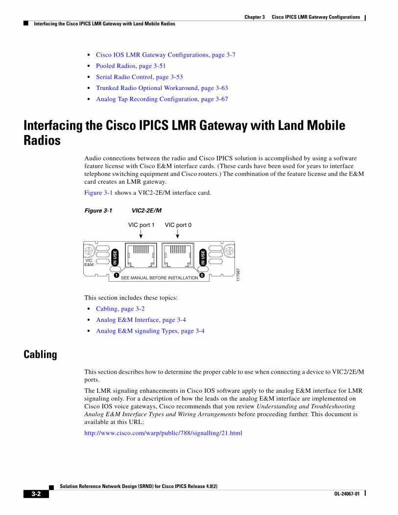
Chapter 3 Cisco IPICS LMR Gateway ConfigurationsInterfacing the Cisco IPICS LMR Gateway with Land Mobile Radios
• Cisco IOS LMR Gateway Configurations, page 3-7
• Pooled Radios, page 3-51
• Serial Radio Control, page 3-53
• Trunked Radio Optional Workaround, page 3-63
• Analog Tap Recording Configuration, page 3-67
Interfacing the Cisco IPICS LMR Gateway with Land Mobile Radios
Audio connections between the radio and Cisco IPICS solution is accomplished by using a software feature license with Cisco E&M interface cards. (These cards have been used for years to interface telephone switching equipment and Cisco routers.) The combination of the feature license and the E&M card creates an LMR gateway.
Figure 3-1 shows a VIC2-2E/M interface card.
Figure 3-1 VIC2-2E/M
This section includes these topics:
• Cabling, page 3-2
• Analog E&M Interface, page 3-4
• Analog E&M signaling Types, page 3-4
CablingThis section describes how to determine the proper cable to use when connecting a device to VIC2/2E/M ports.
The LMR signaling enhancements in Cisco IOS software apply to the analog E&M interface for LMR signaling only. For a description of how the leads on the analog E&M interface are implemented on Cisco IOS voice gateways, Cisco recommends that you review Understanding and Troubleshooting Analog E&M Interface Types and Wiring Arrangements before proceeding further. This document is available at this URL:
http://www.cisco.com/warp/public/788/signalling/21.html
1175
67
SEE MANUAL BEFORE INSTALLATION
VICE&M IN
US
E
IN U
SE
1 0
VIC port 1 VIC port 0
3-2Solution Reference Network Design (SRND) for Cisco IPICS Release 4.0(2)
OL-24067-01
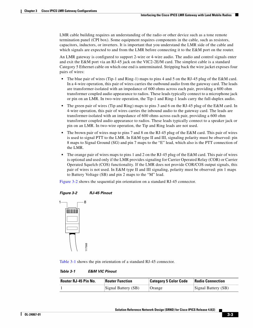
Chapter 3 Cisco IPICS LMR Gateway ConfigurationsInterfacing the Cisco IPICS LMR Gateway with Land Mobile Radios
LMR cable building requires an understanding of the radio or other device such as a tone remote termination panel (CPI box). Some equipment requires components in the cable, such as resistors, capacitors, inductors, or inverters. It is important that you understand the LMR side of the cable and which signals are expected to and from the LMR before connecting it to the E&M port on the router.
An LMR gateway is configured to support 2-wire or 4-wire audio. The audio and control signals enter and exit the E&M port via an RJ-45 jack on the VIC2-2E/M card. The simplest cable is a standard Category 5 Ethernet cable on which one end is unterminated. Stripping back the wire jacket exposes four pairs of wires:
• The blue pair of wires (Tip-1 and Ring-1) maps to pins 4 and 5 on the RJ-45 plug of the E&M card. In a 4-wire operation, this pair of wires carries the outbound audio from the gateway card. The leads are transformer-isolated with an impedance of 600 ohms across each pair, providing a 600 ohm transformer coupled audio appearance to radios. These leads typically connect to a microphone jack or pin on an LMR. In two-wire operation, the Tip-1 and Ring-1 leads carry the full-duplex audio.
• The green pair of wires (Tip and Ring) maps to pins 3 and 6 on the RJ-45 plug of the E&M card. In 4-wire operation, this pair of wires carries the inbound audio to the gateway card. The leads are transformer-isolated with an impedance of 600 ohms across each pair, providing a 600 ohm transformer coupled audio appearance to radios. These leads typically connect to a speaker jack or pin on an LMR. In two-wire operation, the Tip and Ring leads are not used.
• The brown pair of wires map to pins 7 and 8 on the RJ-45 plug of the E&M card. This pair of wires is used to signal PTT to the LMR. In E&M type II and III, signaling polarity must be observed: pin 8 maps to Signal Ground (SG) and pin 7 maps to the “E” lead, which also is the PTT connection of the LMR.
• The orange pair of wires maps to pins 1 and 2 on the RJ-45 plug of the E&M card. This pair of wires is optional and used only if the LMR provides signaling for Carrier Operated Relay (COR) or Carrier Operated Squelch (COS) functionality. If the LMR does not provide COR/COS output signals, this pair of wires is not used. In E&M type II and III signaling, polarity must be observed: pin 1 maps to Battery Voltage (SB) and pin 2 maps to the “M” lead.
Figure 3-2 shows the sequential pin orientation on a standard RJ-45 connector.
Figure 3-2 RJ-45 Pinout
Table 3-1 shows the pin orientation of a standard RJ-45 connector.
1175
68
1 8
Table 3-1 E&M VIC Pinout
Router RJ-45 Pin No. Router Function Category 5 Color Code Radio Connection
1 Signal Battery (SB) Orange Signal Battery (SB)
3-3Solution Reference Network Design (SRND) for Cisco IPICS Release 4.0(2)
OL-24067-01
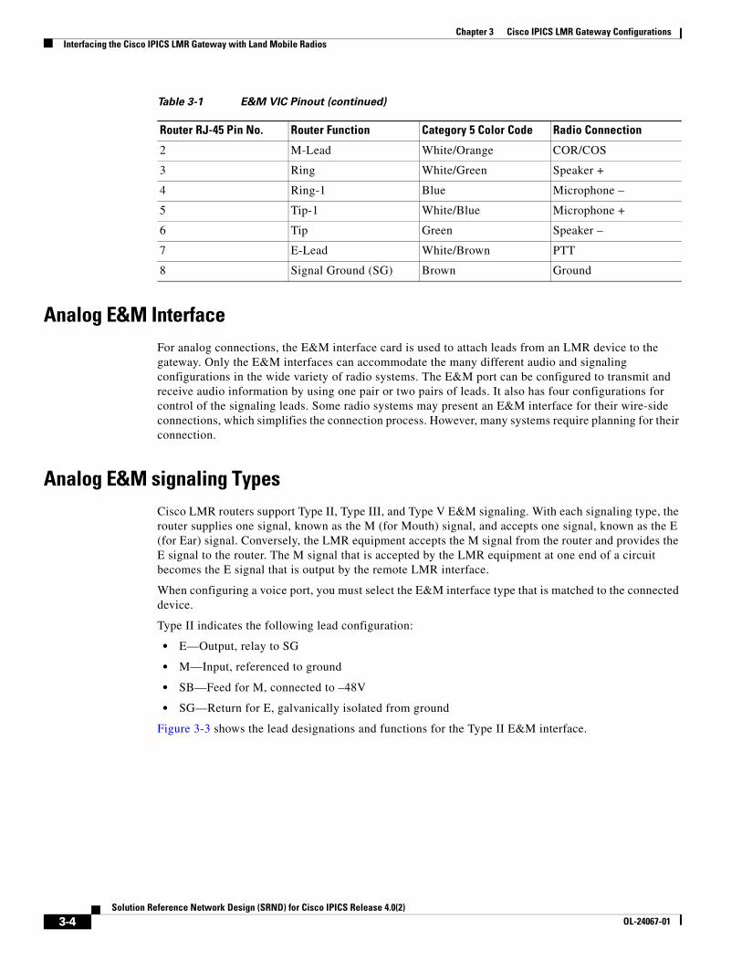
Chapter 3 Cisco IPICS LMR Gateway ConfigurationsInterfacing the Cisco IPICS LMR Gateway with Land Mobile Radios
Analog E&M InterfaceFor analog connections, the E&M interface card is used to attach leads from an LMR device to the gateway. Only the E&M interfaces can accommodate the many different audio and signaling configurations in the wide variety of radio systems. The E&M port can be configured to transmit and receive audio information by using one pair or two pairs of leads. It also has four configurations for control of the signaling leads. Some radio systems may present an E&M interface for their wire-side connections, which simplifies the connection process. However, many systems require planning for their connection.
Analog E&M signaling TypesCisco LMR routers support Type II, Type III, and Type V E&M signaling. With each signaling type, the router supplies one signal, known as the M (for Mouth) signal, and accepts one signal, known as the E (for Ear) signal. Conversely, the LMR equipment accepts the M signal from the router and provides the E signal to the router. The M signal that is accepted by the LMR equipment at one end of a circuit becomes the E signal that is output by the remote LMR interface.
When configuring a voice port, you must select the E&M interface type that is matched to the connected device.
Type II indicates the following lead configuration:
• E—Output, relay to SG
• M—Input, referenced to ground
• SB—Feed for M, connected to –48V
• SG—Return for E, galvanically isolated from ground
Figure 3-3 shows the lead designations and functions for the Type II E&M interface.
2 M-Lead White/Orange COR/COS
3 Ring White/Green Speaker +
4 Ring-1 Blue Microphone –
5 Tip-1 White/Blue Microphone +
6 Tip Green Speaker –
7 E-Lead White/Brown PTT
8 Signal Ground (SG) Brown Ground
Table 3-1 E&M VIC Pinout (continued)
Router RJ-45 Pin No. Router Function Category 5 Color Code Radio Connection
3-4Solution Reference Network Design (SRND) for Cisco IPICS Release 4.0(2)
OL-24067-01
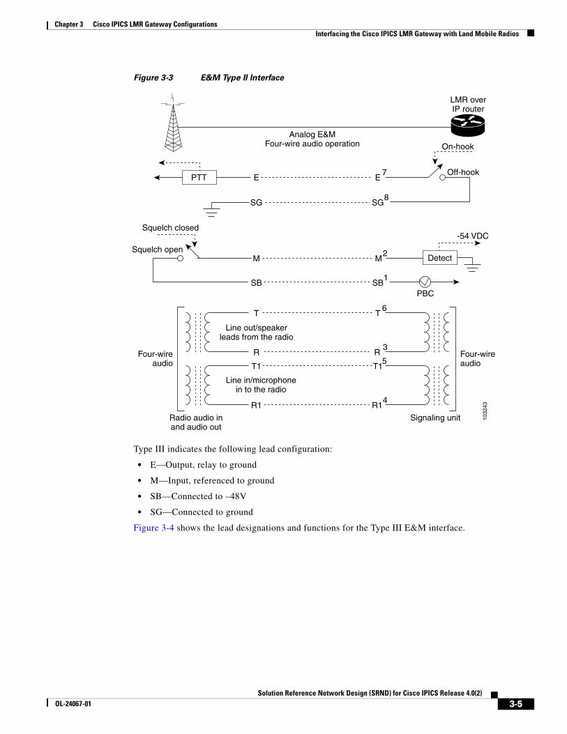
Chapter 3 Cisco IPICS LMR Gateway ConfigurationsInterfacing the Cisco IPICS LMR Gateway with Land Mobile Radios
Figure 3-3 E&M Type II Interface
Type III indicates the following lead configuration:
• E—Output, relay to ground
• M—Input, referenced to ground
• SB—Connected to –48V
• SG—Connected to ground
Figure 3-4 shows the lead designations and functions for the Type III E&M interface.
1032
43
PTT E EOff-hook
On-hook
Analog E&MFour-wire audio operation
7
SG SG8
M M2
SB SBPBC
1
DetectSquelch open
LMR overIP router
Squelch closed
Four-wireaudio
Four-wireaudio
Radio audio inand audio out
Signaling unit
T T6
R R3
T1 T15
R1
-54 VDC
R14
Line out/speaker leads from the radio
Line in/microphone in to the radio
3-5Solution Reference Network Design (SRND) for Cisco IPICS Release 4.0(2)
OL-24067-01
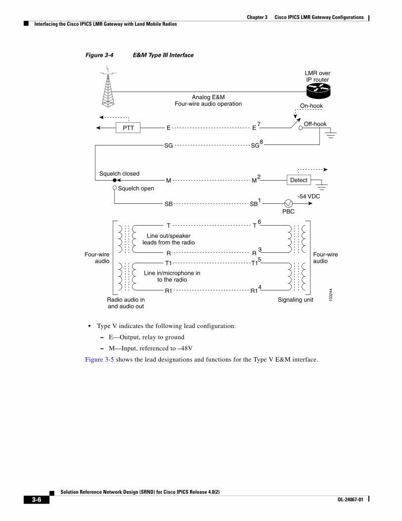
Chapter 3 Cisco IPICS LMR Gateway ConfigurationsInterfacing the Cisco IPICS LMR Gateway with Land Mobile Radios
Figure 3-4 E&M Type III Interface
• Type V indicates the following lead configuration:
– E—Output, relay to ground
– M—Input, referenced to –48V
Figure 3-5 shows the lead designations and functions for the Type V E&M interface.
1032
44
E EOff-hook
On-hook
Analog E&MFour-wire audio operation
7
SG SG8
M M2
SB SBPBC
1
Detect
PTT
Squelch open
LMR overIP router
Squelch closed
Four-wireaudio
Four-wireaudio
Radio audio inand audio out
Signaling unit
T T6
R R3
T1 T15
R1 R14
Line out/speaker leads from the radio
Line in/microphone in to the radio
-54 VDC
3-6Solution Reference Network Design (SRND) for Cisco IPICS Release 4.0(2)
OL-24067-01
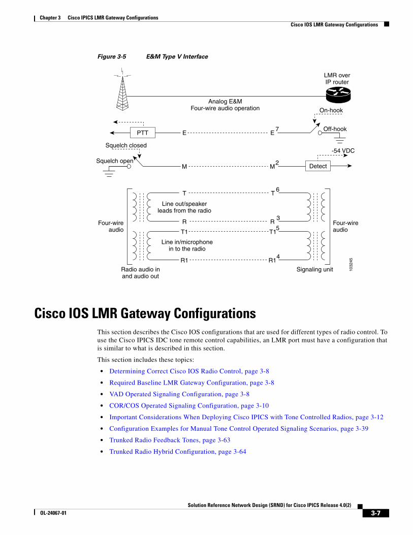
Chapter 3 Cisco IPICS LMR Gateway ConfigurationsCisco IOS LMR Gateway Configurations
Figure 3-5 E&M Type V Interface
Cisco IOS LMR Gateway ConfigurationsThis section describes the Cisco IOS configurations that are used for different types of radio control. To use the Cisco IPICS IDC tone remote control capabilities, an LMR port must have a configuration that is similar to what is described in this section.
This section includes these topics:
• Determining Correct Cisco IOS Radio Control, page 3-8
• Required Baseline LMR Gateway Configuration, page 3-8
• VAD Operated Signaling Configuration, page 3-8
• COR/COS Operated Signaling Configuration, page 3-10
• Important Considerations When Deploying Cisco IPICS with Tone Controlled Radios, page 3-12
• Configuration Examples for Manual Tone Control Operated Signaling Scenarios, page 3-39
• Trunked Radio Feedback Tones, page 3-63
• Trunked Radio Hybrid Configuration, page 3-64
1032
45
PTT E EOff-hook
Squelch open
On-hook
Analog E&MFour-wire audio operation
LMR overIP router
Squelch closed
7
M M2 Detect
Four-wireaudio
Four-wireaudio
Radio audio inand audio out
Signaling unit
T T6
R R3
T1 T15
R1 R14
Line out/speaker leads from the radio
Line in/microphone in to the radio
-54 VDC
3-7Solution Reference Network Design (SRND) for Cisco IPICS Release 4.0(2)
OL-24067-01
Chapter 3 Cisco IPICS LMR Gateway ConfigurationsCisco IOS LMR Gateway Configurations
Determining Correct Cisco IOS Radio ControlRouter configuration and connections typically are determined by the capabilities of the radio to be interfaced. There are three basic types of Cisco IOS radio control configurations. Use the router configuration that best matches your situation.
• VAD Operated Signaling—Typically used when the radio device does not provide COR/COS signaling. Without the COR/COS signaling interface from the radio device, the router uses the voice activation detection (VAD) function within Cisco IOS to determine when a signal is being received from the radio device and to begin sending VoIP packets on the designated multicast address. Typically, this option is used when a portable radio device is the endpoint because these devices do not normally provide signaling for COR/COS.
• COR/COS Signaling—Should be used when a radio device has the ability to provide COR/COS signaling. In this situation, the router begins sending VoIP packets on the assigned multicast address when this line is activated by the radio device. Typically, this approach provides the most reliable audio reception and eliminates the clipping at the beginning of a conversation that may occur when the VAD Operated Signaling function is employed.
• Tone Control Signaling—Should be used if the radio device has a tone control panel interface and uses tone signaling mixed in the audio stream to communicate its activity states to the radio. Typically, a wakeup tone, frequency/function selection tone, and guard tone are generated with the audio to control a radio device. This option typically is found only on base station type radio devices.
Required Baseline LMR Gateway ConfigurationThe following baseline Cisco IOS configuration commands are required regardless of the signaling that is implemented:
ip multicast-routing!voice class codec 1 codec preference 1 g729r8 codec preference 2 g711ulaw!interface Loopback0 ip address 192.168.4.6 255.255.255.255 ip pim sparse-dense-mode!interface Vif1 ip address 192.168.3.5 255.255.255.252 ip pim sparse-dense-mode!interface FastEthernet0/0 description $ETH-LAN$$ETH-SW-LAUNCH$$INTF-INFO-FE 0/0$ ip address 192.168.0.6 255.255.255.0 ip pim sparse-dense-mode duplex auto speed auto
VAD Operated Signaling ConfigurationYou must issue the lmr m-lead inactive command for VAD Operated Signaling. When this configuration is used, the router ignores signals that are sent by voice on the M-lead. The flow of voice packets is determined by VAD. Typically, six of the eight wires are employed.
3-8Solution Reference Network Design (SRND) for Cisco IPICS Release 4.0(2)
OL-24067-01
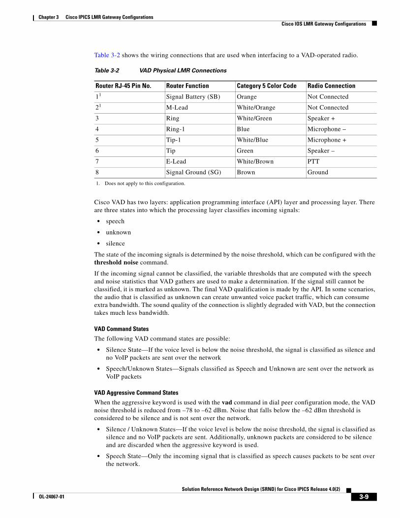
Chapter 3 Cisco IPICS LMR Gateway ConfigurationsCisco IOS LMR Gateway Configurations
Table 3-2 shows the wiring connections that are used when interfacing to a VAD-operated radio.
Cisco VAD has two layers: application programming interface (API) layer and processing layer. There are three states into which the processing layer classifies incoming signals:
• speech
• unknown
• silence
The state of the incoming signals is determined by the noise threshold, which can be configured with the threshold noise command.
If the incoming signal cannot be classified, the variable thresholds that are computed with the speech and noise statistics that VAD gathers are used to make a determination. If the signal still cannot be classified, it is marked as unknown. The final VAD qualification is made by the API. In some scenarios, the audio that is classified as unknown can create unwanted voice packet traffic, which can consume extra bandwidth. The sound quality of the connection is slightly degraded with VAD, but the connection takes much less bandwidth.
VAD Command States
The following VAD command states are possible:
• Silence State—If the voice level is below the noise threshold, the signal is classified as silence and no VoIP packets are sent over the network
• Speech/Unknown States—Signals classified as Speech and Unknown are sent over the network as VoIP packets
VAD Aggressive Command States
When the aggressive keyword is used with the vad command in dial peer configuration mode, the VAD noise threshold is reduced from –78 to –62 dBm. Noise that falls below the –62 dBm threshold is considered to be silence and is not sent over the network.
• Silence / Unknown States—If the voice level is below the noise threshold, the signal is classified as silence and no VoIP packets are sent. Additionally, unknown packets are considered to be silence and are discarded when the aggressive keyword is used.
• Speech State—Only the incoming signal that is classified as speech causes packets to be sent over the network.
Table 3-2 VAD Physical LMR Connections
Router RJ-45 Pin No. Router Function Category 5 Color Code Radio Connection
11
1. Does not apply to this configuration.
Signal Battery (SB) Orange Not Connected
21 M-Lead White/Orange Not Connected
3 Ring White/Green Speaker +
4 Ring-1 Blue Microphone –
5 Tip-1 White/Blue Microphone +
6 Tip Green Speaker –
7 E-Lead White/Brown PTT
8 Signal Ground (SG) Brown Ground
3-9Solution Reference Network Design (SRND) for Cisco IPICS Release 4.0(2)
OL-24067-01
Chapter 3 Cisco IPICS LMR Gateway ConfigurationsCisco IOS LMR Gateway Configurations
The following shows a sample configuration for an LMR voice port that is configured for VAD operated signaling.
In this example, type { 2 | 3 | 5 } typically is type 3, but see Figure 3-3 on page 3-5, Figure 3-4 on page 3-6, and Figure 3-5 on page 3-7 to select the type that best matches your radio requirements. Input gain { -27 - 16 } typically is 10, but adjust this value as needed to best receive audio on Cisco IPICS endpoints. Output attenuation { -16 - 27 } typically is 10, but adjust this value as needed to best receive audio on radios. When connecting a radio to a voice port in an LMR gateway, you may need to make adjustments to properly balance the audio levels. A radio typically provides gain adjustments, and the level of the signal from the radio to the voice port and the level of the signal from the voice port to the radio may require some adjustments on the radio and the voice port. When using a tone controlled radio, it is important to note that the tones that are sent from the LMR gateway to the radio also are affected by the voice ports output attenuation settings. When optimizing these settings to achieve the desired audio levels, take care to ensure that the voice port adjustments do not have an adverse effect on the level and quality of the tone signals.
voice class permanent 1 signal timing oos timeout disabled signal keepalive disabled signal sequence oos no-action!voice-port 0/2/1 voice-class permanent 1 auto-cut-through operation 4-wire type { 2 | 3 | 5 } signal lmr lmr e-lead voice lmr duplex half lmr led-on input gain { -27 - 16 } output attenuation { -16 - 27 } no echo-cancel enable no comfort-noise timeouts call-disconnect 3 timeouts wait-release 3 timing hookflash-in 10 timing hangover 80 timing delay-voice tdm 40 connection trunk 102 description VAD Operated Voice Port threshold noise -40!dial-peer voice 102 voip destination-pattern 102 session protocol multicast session target ipv4:239.193.1.2:21000 codec g711ulaw vad aggressive
COR/COS Operated Signaling ConfigurationWhen the COR/COS operated signaling configuration is used, the router employs signals that are sent by voice on the M-lead pin 2. The M-lead corresponds to the COR/COS of the radio system, which indicates receive activity on the radio system. The lmr m-lead audio-gate-in command configures the voice port to generate VoIP packets only when a seize signal is detected on the M-Lead. The router stops generating VoIP packets when the seize signal is removed from the M-lead. It is important to understand
3-10Solution Reference Network Design (SRND) for Cisco IPICS Release 4.0(2)
OL-24067-01
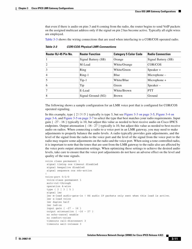
Chapter 3 Cisco IPICS LMR Gateway ConfigurationsCisco IOS LMR Gateway Configurations
that even if there is audio on pins 3 and 6 coming from the radio, the router begins to send VoIP packets on the assigned multicast address only if the signal on pin 2 has become active. Typically all eight wires are employed.
Table 3-3 shows the wiring connections that are used when interfacing to a COR/COS operated radio.
The following shows a sample configuration for an LMR voice port that is configured for COR/COS operated signaling.
In this example, type { 2 | 3 | 5 } typically is type 3, but see Figure 3-3 on page 3-5, Figure 3-4 on page 3-6, and Figure 3-5 on page 3-7 to select the type that best matches your radio requirements. Input gain { -27 - 16 } typically is 10, but adjust this value as needed to best receive audio on Cisco IPICS endpoints. Output attenuation { -16 - 27 } typically is 10, but adjust this value as needed to best receive audio on radios. When connecting a radio to a voice port in an LMR gateway, you may need to make adjustments to properly balance the audio levels. A radio typically provides gain adjustments, and the level of the signal from the radio to the voice port and the level of the signal from the voice port to the radio may require some adjustments on the radio and the voice port. When using a tone controlled radio, it is important to note that the tones that are sent from the LMR gateway to the radio also are affected by the voice ports output attenuation settings. When optimizing these settings to achieve the desired audio levels, take care to ensure that the voice port adjustments do not have an adverse effect on the level and quality of the tone signals.
voice class permanent 1 signal timing oos timeout disabled signal keepalive disabled signal sequence oos n4o-action!voice-port 0/2/0 voice-class permanent 1 auto-cut-through operation 4-wire type { 2 | 3 | 5 } signal lmr lmr m-lead audio-gate-in ! RX audio IP packets only sent when this lead is active. lmr e-lead voice lmr duplex half lmr led-on input gain { -27 - 16 } output attenuation { -16 - 27 } no echo-cancel enable no comfort-noise timeouts call-disconnect 3 timeouts wait-release 3
Table 3-3 COR/COS Physical LMR Connections
Router RJ-45 Pin No. Router Function Category 5 Color Code Radio Connection
1 Signal Battery (SB) Orange Signal Battery (SB)
2 M-Lead White/Orange COR/COS
3 Ring White/Green Speaker +
4 Ring-1 Blue Microphone –
5 Tip-1 White/Blue Microphone +
6 Tip Green Speaker –
7 E-Lead White/Brown PTT
8 Signal Ground (SG) Brown Ground
3-11Solution Reference Network Design (SRND) for Cisco IPICS Release 4.0(2)
OL-24067-01
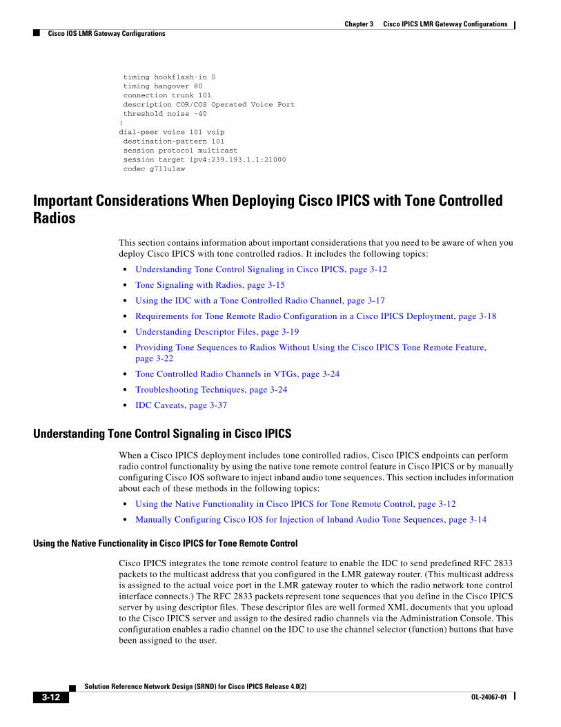
Chapter 3 Cisco IPICS LMR Gateway ConfigurationsCisco IOS LMR Gateway Configurations
timing hookflash-in 0 timing hangover 80 connection trunk 101 description COR/COS Operated Voice Port threshold noise -40!dial-peer voice 101 voip destination-pattern 101 session protocol multicast session target ipv4:239.193.1.1:21000 codec g711ulaw
Important Considerations When Deploying Cisco IPICS with Tone Controlled Radios
This section contains information about important considerations that you need to be aware of when you deploy Cisco IPICS with tone controlled radios. It includes the following topics:
• Understanding Tone Control Signaling in Cisco IPICS, page 3-12
• Tone Signaling with Radios, page 3-15
• Using the IDC with a Tone Controlled Radio Channel, page 3-17
• Requirements for Tone Remote Radio Configuration in a Cisco IPICS Deployment, page 3-18
• Understanding Descriptor Files, page 3-19
• Providing Tone Sequences to Radios Without Using the Cisco IPICS Tone Remote Feature, page 3-22
• Tone Controlled Radio Channels in VTGs, page 3-24
• Troubleshooting Techniques, page 3-24
• IDC Caveats, page 3-37
Understanding Tone Control Signaling in Cisco IPICS
When a Cisco IPICS deployment includes tone controlled radios, Cisco IPICS endpoints can perform radio control functionality by using the native tone remote control feature in Cisco IPICS or by manually configuring Cisco IOS software to inject inband audio tone sequences. This section includes information about each of these methods in the following topics:
• Using the Native Functionality in Cisco IPICS for Tone Remote Control, page 3-12
• Manually Configuring Cisco IOS for Injection of Inband Audio Tone Sequences, page 3-14
Using the Native Functionality in Cisco IPICS for Tone Remote Control
Cisco IPICS integrates the tone remote control feature to enable the IDC to send predefined RFC 2833 packets to the multicast address that you configured in the LMR gateway router. (This multicast address is assigned to the actual voice port in the LMR gateway router to which the radio network tone control interface connects.) The RFC 2833 packets represent tone sequences that you define in the Cisco IPICS server by using descriptor files. These descriptor files are well formed XML documents that you upload to the Cisco IPICS server and assign to the desired radio channels via the Administration Console. This configuration enables a radio channel on the IDC to use the channel selector (function) buttons that have been assigned to the user.
3-12Solution Reference Network Design (SRND) for Cisco IPICS Release 4.0(2)
OL-24067-01
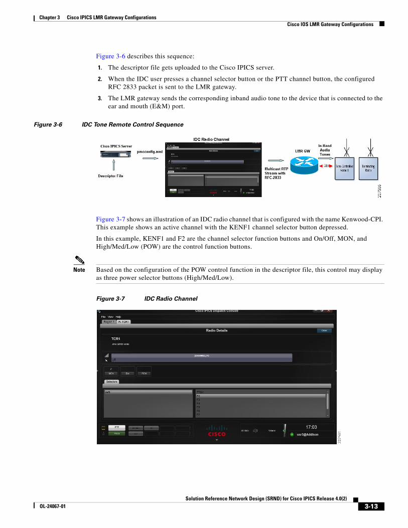
Chapter 3 Cisco IPICS LMR Gateway ConfigurationsCisco IOS LMR Gateway Configurations
Figure 3-6 describes this sequence:
1. The descriptor file gets uploaded to the Cisco IPICS server.
2. When the IDC user presses a channel selector button or the PTT channel button, the configured RFC 2833 packet is sent to the LMR gateway.
3. The LMR gateway sends the corresponding inband audio tone to the device that is connected to the ear and mouth (E&M) port.
Figure 3-6 IDC Tone Remote Control Sequence
Figure 3-7 shows an illustration of an IDC radio channel that is configured with the name Kenwood-CPI. This example shows an active channel with the KENF1 channel selector button depressed.
In this example, KENF1 and F2 are the channel selector function buttons and On/Off, MON, and High/Med/Low (POW) are the control function buttons.
Note Based on the configuration of the POW control function in the descriptor file, this control may display as three power selector buttons (High/Med/Low).
Figure 3-7 IDC Radio Channel
3-13Solution Reference Network Design (SRND) for Cisco IPICS Release 4.0(2)
OL-24067-01
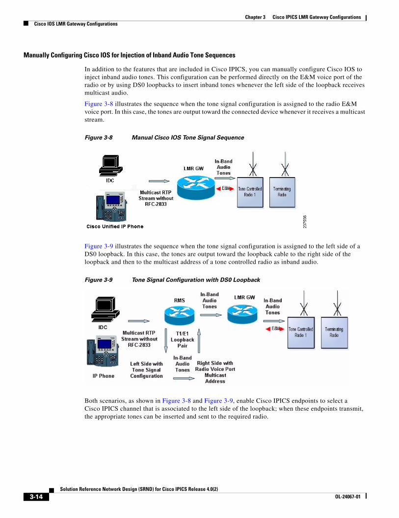
Chapter 3 Cisco IPICS LMR Gateway ConfigurationsCisco IOS LMR Gateway Configurations
Manually Configuring Cisco IOS for Injection of Inband Audio Tone Sequences
In addition to the features that are included in Cisco IPICS, you can manually configure Cisco IOS to inject inband audio tones. This configuration can be performed directly on the E&M voice port of the radio or by using DS0 loopbacks to insert inband tones whenever the left side of the loopback receives multicast audio.
Figure 3-8 illustrates the sequence when the tone signal configuration is assigned to the radio E&M voice port. In this case, the tones are output toward the connected device whenever it receives a multicast stream.
Figure 3-8 Manual Cisco IOS Tone Signal Sequence
Figure 3-9 illustrates the sequence when the tone signal configuration is assigned to the left side of a DS0 loopback. In this case, the tones are output toward the loopback cable to the right side of the loopback and then to the multicast address of a tone controlled radio as inband audio.
Figure 3-9 Tone Signal Configuration with DS0 Loopback
Both scenarios, as shown in Figure 3-8 and Figure 3-9, enable Cisco IPICS endpoints to select a Cisco IPICS channel that is associated to the left side of the loopback; when these endpoints transmit, the appropriate tones can be inserted and sent to the required radio.
3-14Solution Reference Network Design (SRND) for Cisco IPICS Release 4.0(2)
OL-24067-01
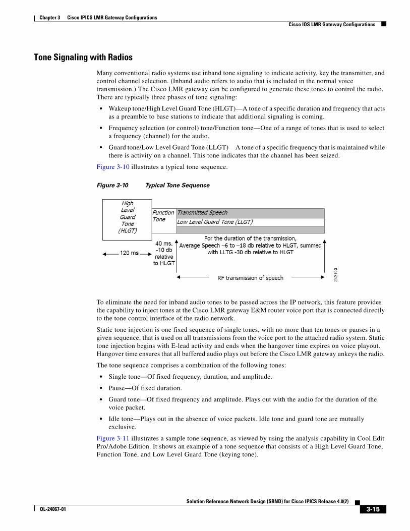
Chapter 3 Cisco IPICS LMR Gateway ConfigurationsCisco IOS LMR Gateway Configurations
Tone Signaling with Radios
Many conventional radio systems use inband tone signaling to indicate activity, key the transmitter, and control channel selection. (Inband audio refers to audio that is included in the normal voice transmission.) The Cisco LMR gateway can be configured to generate these tones to control the radio. There are typically three phases of tone signaling:
• Wakeup tone/High Level Guard Tone (HLGT)—A tone of a specific duration and frequency that acts as a preamble to base stations to indicate that additional signaling is coming.
• Frequency selection (or control) tone/Function tone—One of a range of tones that is used to select a frequency (channel) for the audio.
• Guard tone/Low Level Guard Tone (LLGT)—A tone of a specific frequency that is maintained while there is activity on a channel. This tone indicates that the channel has been seized.
Figure 3-10 illustrates a typical tone sequence.
Figure 3-10 Typical Tone Sequence
To eliminate the need for inband audio tones to be passed across the IP network, this feature provides the capability to inject tones at the Cisco LMR gateway E&M router voice port that is connected directly to the tone control interface of the radio network.
Static tone injection is one fixed sequence of single tones, with no more than ten tones or pauses in a given sequence, that is used on all transmissions from the voice port to the attached radio system. Static tone injection begins with E-lead activity and ends when the hangover time expires on voice playout. Hangover time ensures that all buffered audio plays out before the Cisco LMR gateway unkeys the radio.
The tone sequence comprises a combination of the following tones:
• Single tone—Of fixed frequency, duration, and amplitude.
• Pause—Of fixed duration.
• Guard tone—Of fixed frequency and amplitude. Plays out with the audio for the duration of the voice packet.
• Idle tone—Plays out in the absence of voice packets. Idle tone and guard tone are mutually exclusive.
Figure 3-11 illustrates a sample tone sequence, as viewed by using the analysis capability in Cool Edit Pro/Adobe Edition. It shows an example of a tone sequence that consists of a High Level Guard Tone, Function Tone, and Low Level Guard Tone (keying tone).
3-15Solution Reference Network Design (SRND) for Cisco IPICS Release 4.0(2)
OL-24067-01
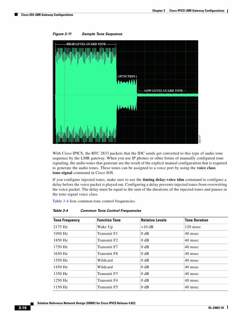
Chapter 3 Cisco IPICS LMR Gateway ConfigurationsCisco IOS LMR Gateway Configurations
Figure 3-11 Sample Tone Sequence
With Cisco IPICS, the RFC 2833 packets that the IDC sends get converted to this type of audio tone sequence by the LMR gateway. When you use IP phones or other forms of manually configured tone signaling, the audio tones that generate are the result of the explicit manual configuration that is required to generate the audio tones. These tones can be assigned to a voice port by using the voice class tone-signal command in Cisco IOS.
If you configure injected tones, make sure to use the timing delay-voice tdm command to configure a delay before the voice packet is played out. Configuring a delay prevents injected tones from overwriting the voice packet. The delay must be equal to the sum of the durations of the injected tones and pauses in the tone-signal voice class.
Table 3-4 lists common tone control frequencies.
Table 3-4 Common Tone Control Frequencies
Tone Frequency Function Tone Relative Levels Tone Duration
2175 Hz Wake Up +10 dB 120 msec
1950 Hz Transmit F1 0 dB 40 msec
1850 Hz Transmit F2 0 dB 40 msec
1750 Hz Transmit F7 0 dB 40 msec
1650 Hz Transmit F8 0 dB 40 msec
1550 Hz Wildcard 0 dB 40 msec
1450 Hz Wildcard 0 dB 40 msec
1350 Hz Transmit F3 0 dB 40 msec
1250 Hz Transmit F4 0 dB 40 msec
1150 Hz Transmit F5 0 dB 40 msec
3-16Solution Reference Network Design (SRND) for Cisco IPICS Release 4.0(2)
OL-24067-01
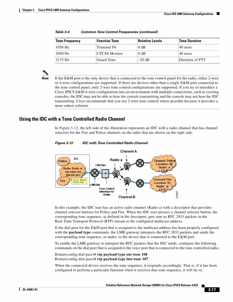
Chapter 3 Cisco IPICS LMR Gateway ConfigurationsCisco IOS LMR Gateway Configurations
Note If the E&M port is the only device that is connected to the tone control panel for the radio, either 2-wire or 4-wire configurations are supported. If there are devices other than a single E&M port connected to the tone control panel, only 2-wire tone control configurations are supported. If you try to introduce a Cisco IPICS E&M 4-wire configuration into an environment with multiple connections, such as existing consoles, the IDC may not be able to hear the console transmitting and the console may not hear the IDC transmitting. Cisco recommends that you use 2-wire tone control where possible because it provides a more robust solution.
Using the IDC with a Tone Controlled Radio Channel
In Figure 3-12, the left side of the illustration represents an IDC with a radio channel that has channel selectors for the Fire and Police channels on the radio that are shown on the right side.
Figure 3-12 IDC with Tone Controlled Radio Channel
In this example, the IDC user has an active radio channel (Radio a) with a descriptor that provides channel selector buttons for Police and Fire. When the IDC user presses a channel selector button, the corresponding tone sequence, as defined in the descriptor, gets sent as RFC 2833 packets in the Real-Time Transport Protocol (RTP) stream to the configured multicast address.
If the dial peer for the E&M port that is assigned to the multicast address has been properly configured with the payload type commands, the LMR gateway interprets the RFC 2833 packets and sends the corresponding tone sequence, as audio, to the device that is connected to the E&M port.
To enable the LMR gateway to interpret the RFC packets that the IDC sends, configure the following commands on the dial peer that is assigned to the voice port that is connected to the tone controlled radio:
Router(config-dial-peer)# rtp payload-type nte-tone 108 Router(config-dial-peer)# rtp payload-type lmr-tone 107
When the connected device receives the tone sequence, it responds accordingly. That is, if it has been configured to perform a particular function when it receives that tone sequence, it will do so.
1050 Hz Transmit F6 0 dB 40 msec
2050 Hz CTCSS Monitor 0 dB 40 msec
2175 Hz Guard Tone –20 dB Duration of PTT
Table 3-4 Common Tone Control Frequencies (continued)
Tone Frequency Function Tone Relative Levels Tone Duration
3-17Solution Reference Network Design (SRND) for Cisco IPICS Release 4.0(2)
OL-24067-01
Chapter 3 Cisco IPICS LMR Gateway ConfigurationsCisco IOS LMR Gateway Configurations
Note In addition to sending the RFC 2833 packets when the channel selector button is pressed, the IDC also sends the RFC 2833 packets on the currently selected channel when the PTT button is pressed. The exact behavior is determined by the descriptor file definitions. More specifically, the actions that you define in the “tune” element occur when the selector is pressed. The actions that you define in the “begintransmit” element occur when the PTT button is pressed. It is typical to define tone sequences in the following way: • tune = HLGT + rfc2833tone • begintransmit = HLGT + rfc2833tone + LLGT
Requirements for Tone Remote Radio Configuration in a Cisco IPICS Deployment
Table 3-5 describes the items that are required for the various tone controlled radio scenarios in a Cisco IPICS deployment. See Table 3-6 and Table 3-7 for a preinstallation form that includes the information that must be provided by the Cisco IPICS integrator and by the radio team.
Table 3-5 Required Items for Tone Controlled Radio Scenarios
Configurable Item When Required Use Cases
Descriptor file For any tone controlled radio that IDC users control
IDC users who perform radio control functions.
E&M voice port For interfacing to any radio
All Cisco IPICS deployments with radios require configuration of voice ports to match the radio interface.
E&M voice port dial peer
For interfacing to any radio
All Cisco IPICS deployments with radios require configuration of a dial peer to establish multicast connectivity to the IP network.
E&M voice port dial peer with the rtp payload-type command defined
For any tone controlled radio that the IDC users control
Cisco IPICS deployments with tone controlled radios require configuration of a dial peer to establish multicast connectivity to the IP network, with the rtp payload type commands, when RFC 2833 packets are sent by IDC clients that perform tone control functions.
Tone signal definition For any tone controlled radio that is controlled by inband audio tone sequences that you define and which are not generated by the LMR gateway as the result of RFC 2833 packets sent by an IDC.
Use tone signal configuration to assign tone sequences to voice ports to enable the injection of inband audio tones into the stream. When no RFC 2833 packets are received, you can perform this configuration on the E&M port or on a DS0 loopback to enable a received multicast stream to cause the tones to be injected through the loopback toward the multicast address that is associated with the voice port, which the tone controlled radio is connected to.
3-18Solution Reference Network Design (SRND) for Cisco IPICS Release 4.0(2)
OL-24067-01
Chapter 3 Cisco IPICS LMR Gateway ConfigurationsCisco IOS LMR Gateway Configurations
Understanding Descriptor Files
Tone descriptor files are well formed XML documents. You upload these documents to the Cisco IPICS server and associate them to radio channels. Cisco IPICS uses these descriptor files to determine which buttons to display on the IDC radio channel and the functionality that each button performs. Uploaded descriptor files reside in the Cisco IPICS database.
By default, the Cisco IPICS installation includes several sample descriptor files. This section references content from the sample file called CPIExample.xml.
Use the following guidelines and references to understand how to properly define the elements within a Cisco IPICS descriptor file:
• All Cisco IPICS descriptor files should begin with the following version and encoding statement: <?xml version=”1.0” encoding=“UTF-8”?>
• Cisco IPICS descriptor files should include the following entries with a “name” attribute that defines the descriptor name. This name displays in the descriptor window in the Cisco PICS Administration Console: <ipics:RadioTypeDescriptor xmlns:ipics=“urn:com.cisco.ipics.RadioDescriptor” xmlns:xsi=“http://www.w3.org/2001/XMLSchema-instance”
xsi:schemaLocation=“urn:com.cisco.ipics.RadioDescriptor ../RadioDescriptor.xsd ” name=“CPI Example”>
Commands
The Commands tag defines the reusable CommandRefs that can be used throughout the descriptor file. For example, if the High Level Guard Tone (HLGT) is always going to be a 2175 Hz signal at 0 dB for 120 ms, you can define a command with an ID of “hlgt.” The “hglt” CommanRef can then be used throughout the Channel tags to indicate that it is the desired tone to be used.
<Commands> <Command id="hlgt"> <Rfc2833Tone db="0" duration="120" frequency="2175" /> </Command> <Command id="llgt"> <Rfc2833Tone db="-30" duration="0" frequency="2175" /> </Command> <Command id="dtmf-5"> <Rfc2833Event db="-30" duration="20" event="5" /> </Command></Commands>
Manually configured DS0 loopbacks
For inband audio tone sequences that need to be generated as the result of a Cisco IPICS user sending a multicast stream without RFC 2833 packets.
Use for a Cisco IPICS IP phone user, or an IDC user with a regular channel, to transmit toward a multicast channel that is received at one side of a loopback. This action results in the tones being injected and sent toward the other side of the loopback. The other side of the loopback is assigned to a multicast address that is being used by a voice port connected to a tone controlled radio.
Table 3-5 Required Items for Tone Controlled Radio Scenarios (continued)
Configurable Item When Required Use Cases
3-19Solution Reference Network Design (SRND) for Cisco IPICS Release 4.0(2)
OL-24067-01
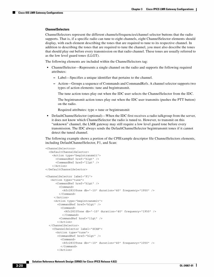
Chapter 3 Cisco IPICS LMR Gateway ConfigurationsCisco IOS LMR Gateway Configurations
ChannelSelectors
ChannelSelectors represent the different channels/frequencies/channel selector buttons that the radio supports. That is, if a specific radio can tune to eight channels, eight ChannelSelector elements should display, with each element describing the tones that are required to tune to its respective channel. In addition to describing the tones that are required to tune the channel, you must also describe the tones that should play out before every transmission on that radio channel. These tones are usually referred to as the low level guard tones (LLGT).
The following elements are included within the ChannelSelectors tag:
• ChannelSelector—Represents a single channel on the radio and supports the following required attributes:
– Label—Specifies a unique identifier that pertains to the channel.
– Action—Groups a sequence of Commands and CommandRefs. A channel selector supports two types of action elements: tune and begintransmit.
The tune action tones play out when the IDC user selects the ChannelSelector from the IDC.
The begintransmit action tones play out when the IDC user transmits (pushes the PTT button) on the radio.
Required attributes: type = tune or begintransmit
• DefaultChannelSelector (optional)—When the IDC first receives a radio talkgroup from the server, it does not know which ChannelSelector the radio is tuned to. However, to transmit on this “unknown” channel, the LMR gateway may still require a low level guard tone before every transmission. The IDC always sends the DefaultChannelSelector begintransmit tones if it cannot detect the tuned channel.
The following example shows a portion of the CPIExample descriptor file ChannelSelectors elements, including DefaultChannelSelector, F1, and Scan:
<ChannelSelectors> <DefaultChannelSelector> <Action type="begintransmit"> <CommandRef href="hlgt" /> <CommandRef href="llgt" /> </Action></DefaultChannelSelector>
<ChannelSelector label="F1"> <Action type="tune"> <CommandRef href="hlgt" /> <Command> <Rfc2833Tone db="-10" duration="40" frequency="1950" /> </Command> </Action> <Action type="begintransmit"> <CommandRef href="hlgt" /> <Command> <Rfc2833Tone db="-10" duration="40" frequency="1950" /> </Command> <CommandRef href="llgt" /> </Action> </ChannelSelector> <ChannelSelector label="SCAN"> <Action type="tune"> <CommandRef href="hlgt" /> <Command> <Rfc2833Tone db="-10" duration="40" frequency="1050" /> </Command> </Action>
3-20Solution Reference Network Design (SRND) for Cisco IPICS Release 4.0(2)
OL-24067-01
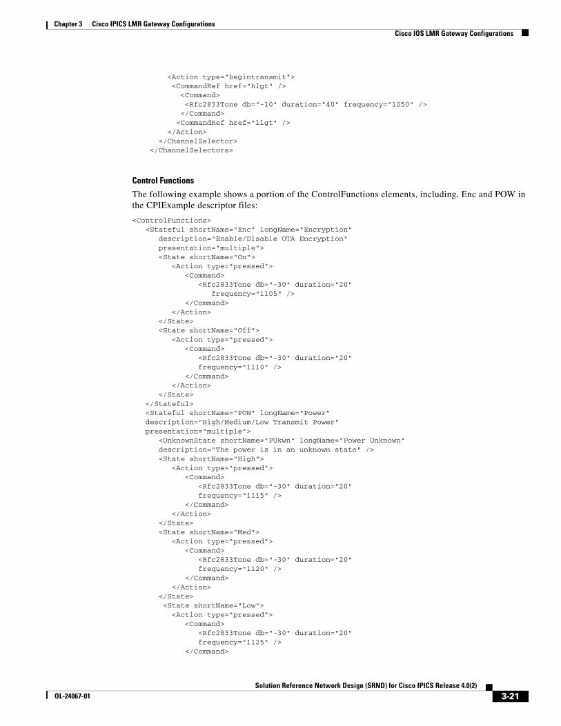
Chapter 3 Cisco IPICS LMR Gateway ConfigurationsCisco IOS LMR Gateway Configurations
<Action type="begintransmit"> <CommandRef href="hlgt" /> <Command> <Rfc2833Tone db="-10" duration="40" frequency="1050" /> </Command> <CommandRef href="llgt" /> </Action> </ChannelSelector> </ChannelSelectors>
Control Functions
The following example shows a portion of the ControlFunctions elements, including, Enc and POW in the CPIExample descriptor files:
<ControlFunctions> <Stateful shortName="Enc" longName="Encryption" description="Enable/Disable OTA Encryption" presentation="multiple"> <State shortName="On"> <Action type="pressed"> <Command> <Rfc2833Tone db="-30" duration="20" frequency="1105" /> </Command> </Action> </State> <State shortName="Off"> <Action type="pressed"> <Command> <Rfc2833Tone db="-30" duration="20" frequency="1110" /> </Command> </Action> </State> </Stateful> <Stateful shortName="POW" longName="Power" description="High/Medium/Low Transmit Power" presentation="multiple"> <UnknownState shortName="PUkwn" longName="Power Unknown" description="The power is in an unknown state" /> <State shortName="High"> <Action type="pressed"> <Command> <Rfc2833Tone db="-30" duration="20" frequency="1115" /> </Command> </Action> </State> <State shortName="Med"> <Action type="pressed"> <Command> <Rfc2833Tone db="-30" duration="20" frequency="1120" /> </Command> </Action> </State> <State shortName="Low"> <Action type="pressed"> <Command> <Rfc2833Tone db="-30" duration="20" frequency="1125" /> </Command>
3-21Solution Reference Network Design (SRND) for Cisco IPICS Release 4.0(2)
OL-24067-01
Chapter 3 Cisco IPICS LMR Gateway ConfigurationsCisco IOS LMR Gateway Configurations
</Action> </State> </Stateful></ControlFunctions>
Providing Tone Sequences to Radios Without Using the Cisco IPICS Tone Remote Feature
In addition to the IDC tone remote feature implementation in Cisco IPICS, you can also leverage Cisco IOS to send tone sequences as inband audio in an RTP stream. This approach can be used in Cisco IPICS deployments with, or instead of, the Cisco IPICS native tone remote capabilities.
Note Although it is possible to mix the Cisco IPICS IDC tone remote feature with manually defined tone configurations, care must be taken to fully understand the limitations and caveats before you do so.
The following sections describe how to deploy, and interface to, various types of radios, including those that are tone controlled. For information about caveats, see the “Caveats” section on page 3-23. For information about how to configure Cisco IOS to enable the insertion of tone sequences in the multicast stream by leveraging loopbacked DS0s, see the “2-Wire Tone Control Configuration for Two-Ten Frequencies” section on page 3-41.
In a Cisco IPICS deployment, you may have a need to allow a Cisco IPICS user to transmit to a tone remote controlled radio from an IP phone by using the Cisco IPICS XML client. Because the IP phone does not support sending RFC 2833 packets, you can manually configure the insertion of the required tones as inband audio by using DS0 loopback ports.
For example, an IP phone user with assigned channels that are configured with the required loopback and tone signal configuration can select a channel and key the radio when they transmit on the corresponding channel. To switch channels, the IP phone user simply selects another configured channel that also has the corresponding manual loopback configuration, and transmits on that channel. This approach enables Cisco IPICS users to control tone controlled radio networks without using RFC 2833 packets.
Figure 3-13 illustrates an IP phone user sending audio on a channel.
1. The audio is received on a router that has DS0 loopbacks configured (in this example, the router is an RMS).
2. The channel (in Cisco IPICS) is assigned the same multicast address as the left side of the loopback.
3. When the audio is received on the left side of the loopback pair, the associated voice port tone signal commands cause the desired inband tone sequence to be sent out the loopbacks TDM interface.
4. The tones are received on the right side of the loopback pair.
5. This audio stream now contains the desired inband audio that gets sent to the right side multicast address.
6. The right side multicast address should match the address that is configured on the radio voice port.
7. The static tone sequence gets sent to the connected tone controlled radio, which causes it to select the corresponding channel and key the radio transmit.
Note Care should be taken to ensure that the tones are inserted as close to the LMR gateway as possible to avoid transmitting the tones across a WAN link or experiencing other topology-related degradation.
3-22Solution Reference Network Design (SRND) for Cisco IPICS Release 4.0(2)
OL-24067-01
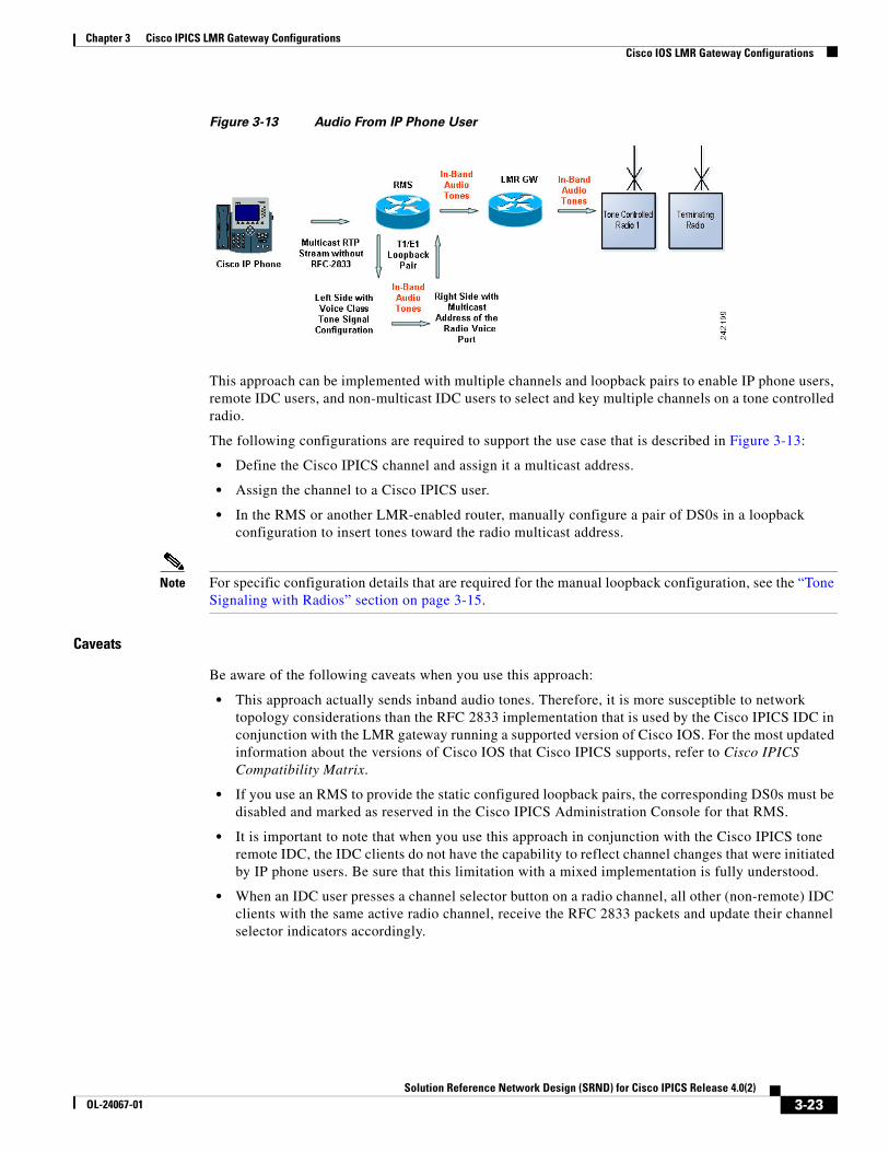
Chapter 3 Cisco IPICS LMR Gateway ConfigurationsCisco IOS LMR Gateway Configurations
Figure 3-13 Audio From IP Phone User
This approach can be implemented with multiple channels and loopback pairs to enable IP phone users, remote IDC users, and non-multicast IDC users to select and key multiple channels on a tone controlled radio.
The following configurations are required to support the use case that is described in Figure 3-13:
• Define the Cisco IPICS channel and assign it a multicast address.
• Assign the channel to a Cisco IPICS user.
• In the RMS or another LMR-enabled router, manually configure a pair of DS0s in a loopback configuration to insert tones toward the radio multicast address.
Note For specific configuration details that are required for the manual loopback configuration, see the “Tone Signaling with Radios” section on page 3-15.
Caveats
Be aware of the following caveats when you use this approach:
• This approach actually sends inband audio tones. Therefore, it is more susceptible to network topology considerations than the RFC 2833 implementation that is used by the Cisco IPICS IDC in conjunction with the LMR gateway running a supported version of Cisco IOS. For the most updated information about the versions of Cisco IOS that Cisco IPICS supports, refer to Cisco IPICS Compatibility Matrix.
• If you use an RMS to provide the static configured loopback pairs, the corresponding DS0s must be disabled and marked as reserved in the Cisco IPICS Administration Console for that RMS.
• It is important to note that when you use this approach in conjunction with the Cisco IPICS tone remote IDC, the IDC clients do not have the capability to reflect channel changes that were initiated by IP phone users. Be sure that this limitation with a mixed implementation is fully understood.
• When an IDC user presses a channel selector button on a radio channel, all other (non-remote) IDC clients with the same active radio channel, receive the RFC 2833 packets and update their channel selector indicators accordingly.
3-23Solution Reference Network Design (SRND) for Cisco IPICS Release 4.0(2)
OL-24067-01
Chapter 3 Cisco IPICS LMR Gateway ConfigurationsCisco IOS LMR Gateway Configurations
Tone Controlled Radio Channels in VTGs
In certain situations, the tones that are required to key a radio do not get sent if more than one radio channel is included in a VTG. Therefore, consider the following key points when you add multiple radio channels to a VTG and see the “VTG Caveats” section on page 3-24.
• When a Cisco IPICS IDC uses a radio channel, it transmits RFC 2833 packets on its configured multicast address. These packets should arrive at the LMR gateway that hosts the E&M voice port that is connected to the tone controlled radio. In this scenario, the LMR gateway interprets the RFC 2833 packets and sends the corresponding tones to the connected device (on the E&M port).
• In addition to the voice port, the RMS that hosts the VTG loopbacks also receives the RFC 2833 packets from the IDC. However, when the loopbacks are used to mix the received RTP stream to the other multicast addresses in the VTG, the RFC packets are lost. That is, the RFC 2833 packets that the IDC transmits are not sent to devices that are listening to any other radio channels in the VTG. The result is that the LMR gateway does not insert the tones that are required to key those radios.
To ensure that the tones are generated to key the radios, you can manually configure the radio voice ports. This configuration requires that you assign a voice class tone-signal configuration to the voice port to which the radio is connected. This configuration must include the tone sequence that is required to key the radio.
In some cases, the radio can be keyed on the currently selected channel. In other cases, the tone sequence must include a channel selector function tone. If a function tone is required, that radio may only use a specific channel when it is in a VTG with another radio.
VTG Caveats
Be aware of the following caveats that pertain to VTGs:
• The radio must be programmed for a keying sequence that does not include a function tone for channel selection, or the tone sequence must contain a static channel selection sequence, which limits that radio base station, when it receives audio from another device in a VTG, to use one particular channel.
• The Cisco IOS gateway software gives precedence to the RFC 2833 packets over a manual configuration when both are present. This means that while it is acceptable to have both, make sure that all participants fully understand the potential effects of this scenario.
Troubleshooting Techniques
When you debug issues with tone controlled radios in a Cisco IPICS deployment, the most important step is to establish that the integrity of the tones that are sent to the connected tone controlled radio network match what the radio expects.
The Cisco IPICS integrator is responsible for proving that the tone sequence is correctly provided at the point of demarcation. This point should be the electrical interface of the E&M voice port. To do so, the integrator must be able to capture audio streams for analysis.
You can use the following technique to confirm that the required tone sequence is present at the E&M interface.
When interfacing to the tone control interface of a radio system, you must know which tone sequences are required to control the radio functions.
3-24Solution Reference Network Design (SRND) for Cisco IPICS Release 4.0(2)
OL-24067-01
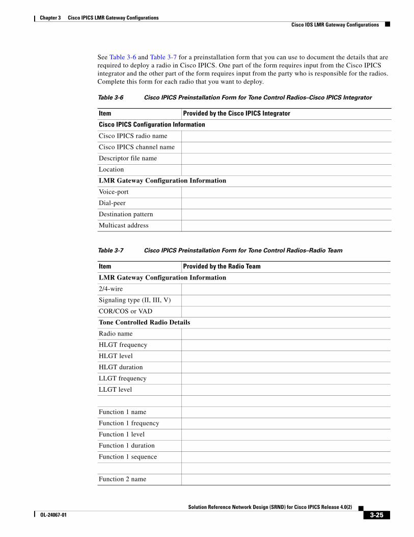
Chapter 3 Cisco IPICS LMR Gateway ConfigurationsCisco IOS LMR Gateway Configurations
See Table 3-6 and Table 3-7 for a preinstallation form that you can use to document the details that are required to deploy a radio in Cisco IPICS. One part of the form requires input from the Cisco IPICS integrator and the other part of the form requires input from the party who is responsible for the radios. Complete this form for each radio that you want to deploy.
Table 3-6 Cisco IPICS Preinstallation Form for Tone Control Radios–Cisco IPICS Integrator
Item Provided by the Cisco IPICS Integrator
Cisco IPICS Configuration Information
Cisco IPICS radio name
Cisco IPICS channel name
Descriptor file name
Location
LMR Gateway Configuration Information
Voice-port
Dial-peer
Destination pattern
Multicast address
Table 3-7 Cisco IPICS Preinstallation Form for Tone Control Radios–Radio Team
Item Provided by the Radio Team
LMR Gateway Configuration Information
2/4-wire
Signaling type (II, III, V)
COR/COS or VAD
Tone Controlled Radio Details
Radio name
HLGT frequency
HLGT level
HLGT duration
LLGT frequency
LLGT level
Function 1 name
Function 1 frequency
Function 1 level
Function 1 duration
Function 1 sequence
Function 2 name
3-25Solution Reference Network Design (SRND) for Cisco IPICS Release 4.0(2)
OL-24067-01

Chapter 3 Cisco IPICS LMR Gateway ConfigurationsCisco IOS LMR Gateway Configurations
Function 2 frequency
Function 2 level
Function 2 duration
Function 2 sequence
Function 3 name
Function 3 frequency
Function 3 level
Function 3 duration
Function 3 sequence
Function 4 name
Function 4 frequency
Function 4 level
Function 4 duration
Function 4 sequence
Function 5 name
Function 5 frequency
Function 5 level
Function 5 duration
Function 5 sequence
Function 5 name
Function 6 name
Function 6 frequency
Function 6 level
Function 6 duration
Function 6 sequence
Function 7 name
Function 7 frequency
Function 7 level
Function 7 duration
Function 7 sequence
Function 8 name
Table 3-7 Cisco IPICS Preinstallation Form for Tone Control Radios–Radio Team (continued)
Item Provided by the Radio Team
3-26Solution Reference Network Design (SRND) for Cisco IPICS Release 4.0(2)
OL-24067-01
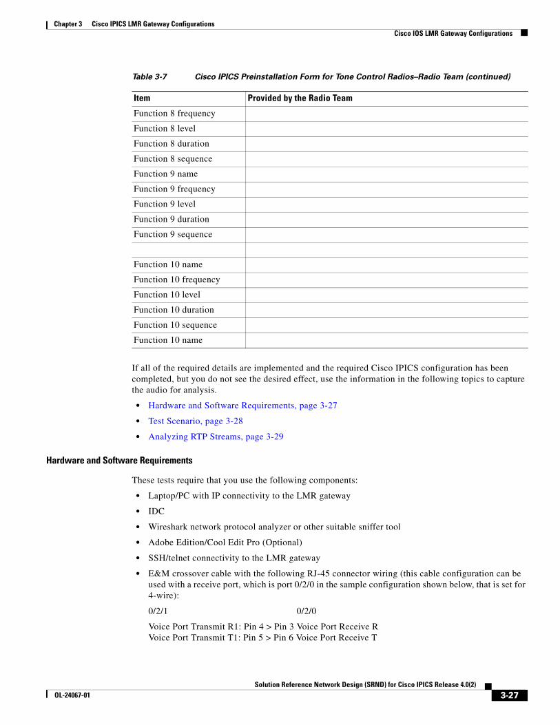
Chapter 3 Cisco IPICS LMR Gateway ConfigurationsCisco IOS LMR Gateway Configurations
If all of the required details are implemented and the required Cisco IPICS configuration has been completed, but you do not see the desired effect, use the information in the following topics to capture the audio for analysis.
• Hardware and Software Requirements, page 3-27
• Test Scenario, page 3-28
• Analyzing RTP Streams, page 3-29
Hardware and Software Requirements
These tests require that you use the following components:
• Laptop/PC with IP connectivity to the LMR gateway
• IDC
• Wireshark network protocol analyzer or other suitable sniffer tool
• Adobe Edition/Cool Edit Pro (Optional)
• SSH/telnet connectivity to the LMR gateway
• E&M crossover cable with the following RJ-45 connector wiring (this cable configuration can be used with a receive port, which is port 0/2/0 in the sample configuration shown below, that is set for 4-wire):
0/2/1 0/2/0
Voice Port Transmit R1: Pin 4 > Pin 3 Voice Port Receive R Voice Port Transmit T1: Pin 5 > Pin 6 Voice Port Receive T
Function 8 frequency
Function 8 level
Function 8 duration
Function 8 sequence
Function 9 name
Function 9 frequency
Function 9 level
Function 9 duration
Function 9 sequence
Function 10 name
Function 10 frequency
Function 10 level
Function 10 duration
Function 10 sequence
Function 10 name
Table 3-7 Cisco IPICS Preinstallation Form for Tone Control Radios–Radio Team (continued)
Item Provided by the Radio Team
3-27Solution Reference Network Design (SRND) for Cisco IPICS Release 4.0(2)
OL-24067-01
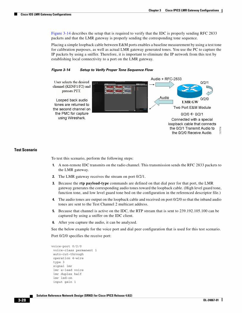
Chapter 3 Cisco IPICS LMR Gateway ConfigurationsCisco IOS LMR Gateway Configurations
Figure 3-14 describes the setup that is required to verify that the IDC is properly sending RFC 2833 packets and that the LMR gateway is properly sending the corresponding tone sequence.
Placing a simple loopback cable between E&M ports enables a baseline measurement by using a test tone for calibration purposes, as well as actual LMR gateway generated tones. You use the PC to capture the IP packets by using a sniffer. Therefore, it is important to eliminate the IP network from this test by establishing local connectivity to a port on the LMR gateway.
Figure 3-14 Setup to Verify Proper Tone Sequence Flow
Test Scenario
To test this scenario, perform the following steps:
1. A non-remote IDC transmits on the radio channel. This transmission sends the RFC 2833 packets to the LMR gateway.
2. The LMR gateway receives the stream on port 0/2/1.
3. Because the rtp payload-type commands are defined on that dial peer for that port, the LMR gateway generates the corresponding audio tones toward the loopback cable. (High level guard tone, function tone, and low level guard tone bed on the configuration in the referenced descriptor file.)
4. The audio tones are output on the loopback cable and received on port 0/2/0 so that the inband audio tones are sent to the Test Channel 2 multicast address.
5. Because that channel is active on the IDC, the RTP stream that is sent to 239.192.105.100 can be captured by using a sniffer on the IDC client.
6. After you capture the audio, it can be analyzed.
See the below example for the voice port and dial peer configuration that is used for this test scenario.
Port 0/2/0 specifies the receive port:
voice-port 0/2/0 voice-class permanent 1 auto-cut-through operation 4-wire type 3 signal lmr lmr e-lead voice lmr duplex half lmr led-on input gain 1
3-28Solution Reference Network Design (SRND) for Cisco IPICS Release 4.0(2)
OL-24067-01
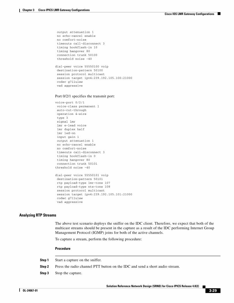
Chapter 3 Cisco IPICS LMR Gateway ConfigurationsCisco IOS LMR Gateway Configurations
output attenuation 1 no echo-cancel enable no comfort-noise timeouts call-disconnect 3 timing hookflash-in 10 timing hangover 80 connection trunk 50100 threshold noise -40
dial-peer voice 55550100 voip destination-pattern 50100 session protocol multicast session target ipv4:239.192.105.100:21000 codec g711ulaw vad aggressive
Port 0/2/1 specifies the transmit port:
voice-port 0/2/1 voice-class permanent 1 auto-cut-through operation 4-wire type 3 signal lmr lmr e-lead voice lmr duplex half lmr led-on input gain 1 output attenuation 1 no echo-cancel enable no comfort-noise timeouts call-disconnect 3 timing hookflash-in 0 timing hangover 80 connection trunk 50101threshold noise -40
dial-peer voice 55550101 voip destination-pattern 50101 rtp payload-type lmr-tone 107 rtp payload-type nte-tone 108 session protocol multicast session target ipv4:239.192.105.101:21000 codec g711ulaw vad aggressive
Analyzing RTP Streams
The above test scenario deploys the sniffer on the IDC client. Therefore, we expect that both of the multicast streams should be present in the capture as a result of the IDC performing Internet Group Management Protocol (IGMP) joins for both of the active channels.
To capture a stream, perform the following procedure:
Procedure
Step 1 Start a capture on the sniffer.
Step 2 Press the radio channel PTT button on the IDC and send a short audio stream.
Step 3 Stop the capture.
3-29Solution Reference Network Design (SRND) for Cisco IPICS Release 4.0(2)
OL-24067-01
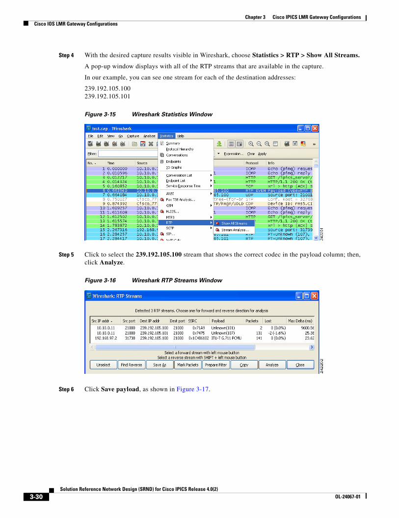
Chapter 3 Cisco IPICS LMR Gateway ConfigurationsCisco IOS LMR Gateway Configurations
Step 4 With the desired capture results visible in Wireshark, choose Statistics > RTP > Show All Streams.
A pop-up window displays with all of the RTP streams that are available in the capture.
In our example, you can see one stream for each of the destination addresses:
239.192.105.100 239.192.105.101
Figure 3-15 Wireshark Statistics Window
Step 5 Click to select the 239.192.105.100 stream that shows the correct codec in the payload column; then, click Analyze.
Figure 3-16 Wireshark RTP Streams Window
Step 6 Click Save payload, as shown in Figure 3-17.
3-30Solution Reference Network Design (SRND) for Cisco IPICS Release 4.0(2)
OL-24067-01
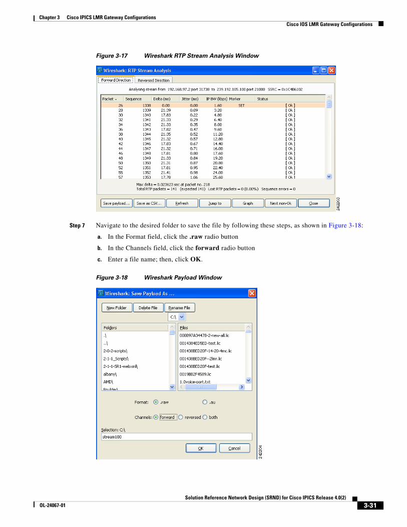
Chapter 3 Cisco IPICS LMR Gateway ConfigurationsCisco IOS LMR Gateway Configurations
Figure 3-17 Wireshark RTP Stream Analysis Window
Step 7 Navigate to the desired folder to save the file by following these steps, as shown in Figure 3-18:
a. In the Format field, click the .raw radio button
b. In the Channels field, click the forward radio button
c. Enter a file name; then, click OK.
Figure 3-18 Wireshark Payload Window
3-31Solution Reference Network Design (SRND) for Cisco IPICS Release 4.0(2)
OL-24067-01
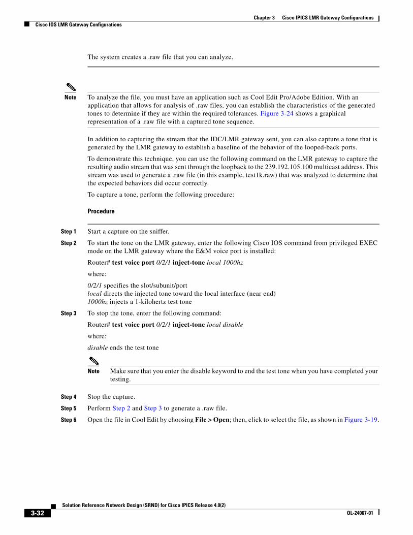
Chapter 3 Cisco IPICS LMR Gateway ConfigurationsCisco IOS LMR Gateway Configurations
The system creates a .raw file that you can analyze.
Note To analyze the file, you must have an application such as Cool Edit Pro/Adobe Edition. With an application that allows for analysis of .raw files, you can establish the characteristics of the generated tones to determine if they are within the required tolerances. Figure 3-24 shows a graphical representation of a .raw file with a captured tone sequence.
In addition to capturing the stream that the IDC/LMR gateway sent, you can also capture a tone that is generated by the LMR gateway to establish a baseline of the behavior of the looped-back ports.
To demonstrate this technique, you can use the following command on the LMR gateway to capture the resulting audio stream that was sent through the loopback to the 239.192.105.100 multicast address. This stream was used to generate a .raw file (in this example, test1k.raw) that was analyzed to determine that the expected behaviors did occur correctly.
To capture a tone, perform the following procedure:
Procedure
Step 1 Start a capture on the sniffer.
Step 2 To start the tone on the LMR gateway, enter the following Cisco IOS command from privileged EXEC mode on the LMR gateway where the E&M voice port is installed:
Router# test voice port 0/2/1 inject-tone local 1000hz
where:
0/2/1 specifies the slot/subunit/port local directs the injected tone toward the local interface (near end) 1000hz injects a 1-kilohertz test tone
Step 3 To stop the tone, enter the following command:
Router# test voice port 0/2/1 inject-tone local disable
where:
disable ends the test tone
Note Make sure that you enter the disable keyword to end the test tone when you have completed your testing.
Step 4 Stop the capture.
Step 5 Perform Step 2 and Step 3 to generate a .raw file.
Step 6 Open the file in Cool Edit by choosing File > Open; then, click to select the file, as shown in Figure 3-19.
3-32Solution Reference Network Design (SRND) for Cisco IPICS Release 4.0(2)
OL-24067-01
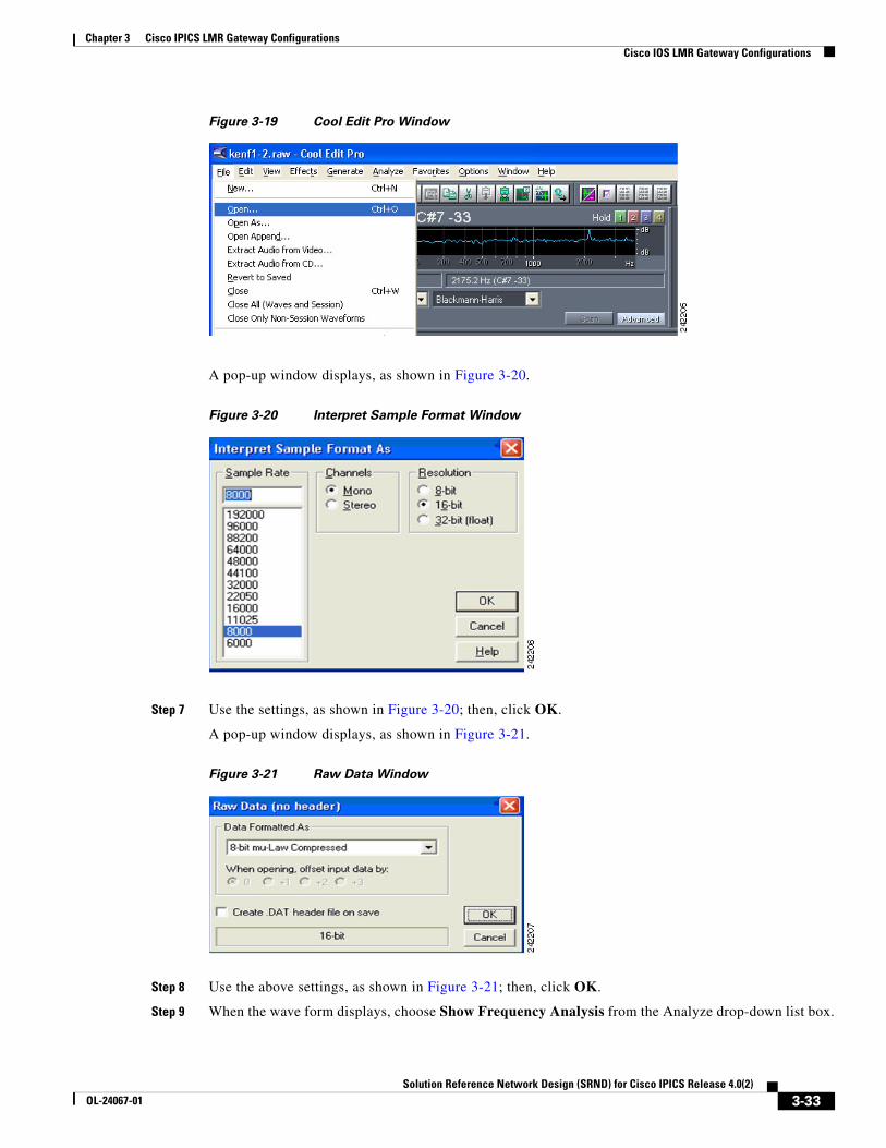
Chapter 3 Cisco IPICS LMR Gateway ConfigurationsCisco IOS LMR Gateway Configurations
Figure 3-19 Cool Edit Pro Window
A pop-up window displays, as shown in Figure 3-20.
Figure 3-20 Interpret Sample Format Window
Step 7 Use the settings, as shown in Figure 3-20; then, click OK.
A pop-up window displays, as shown in Figure 3-21.
Figure 3-21 Raw Data Window
Step 8 Use the above settings, as shown in Figure 3-21; then, click OK.
Step 9 When the wave form displays, choose Show Frequency Analysis from the Analyze drop-down list box.
3-33Solution Reference Network Design (SRND) for Cisco IPICS Release 4.0(2)
OL-24067-01
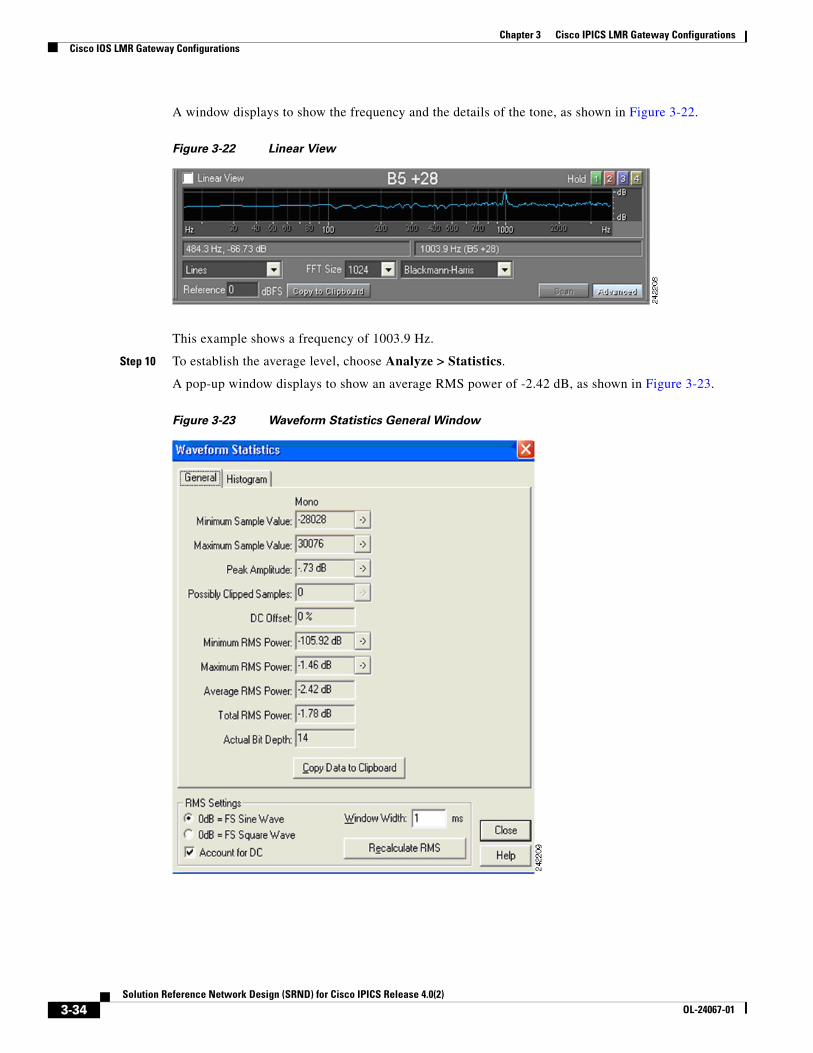
Chapter 3 Cisco IPICS LMR Gateway ConfigurationsCisco IOS LMR Gateway Configurations
A window displays to show the frequency and the details of the tone, as shown in Figure 3-22.
Figure 3-22 Linear View
This example shows a frequency of 1003.9 Hz.
Step 10 To establish the average level, choose Analyze > Statistics.
A pop-up window displays to show an average RMS power of -2.42 dB, as shown in Figure 3-23.
Figure 3-23 Waveform Statistics General Window
3-34Solution Reference Network Design (SRND) for Cisco IPICS Release 4.0(2)
OL-24067-01

Chapter 3 Cisco IPICS LMR Gateway ConfigurationsCisco IOS LMR Gateway Configurations
Because this sample was the result of the inject tone command that we entered, the frequency is expected to be 1000 Hz sent at 0 dB, which is very close to the expected results. You can take several more samples to analyze and determine consistency.
To analyze the tone sequence that was captured when the IDC transmitted on radio channel 1, follow the procedure to capture the stream, generate the .raw file, and open it. You should see an alignment with the settings that are specified in the descriptor file that is associated with the radio channel. In this example, we expect the following results:
• HLGT— 2175 Hz at 0 dB for 120 ms
• Function Tone—1950 Hz at -10 dB for 40 ms
• LLGT— 2175 Hz at -30 dB for the duration of the seizure
Figure 3-24 shows the contents of the captured.raw file.
Figure 3-24 Graphical Representation of a .raw File with a Captured Tone Sequence
To analyze each tone in the sequence, perform the following procedure:
Procedure
Step 1 Select the portion of the wave that you want to analyze by pressing the left mouse button and dragging over a section of the wave form; then, release the mouse button.
Step 2 After you select a section of the wave, check the bottom right corner to see the length of the highlighted section.
In the example, we expect the HLGT length to be 120ms.
3-35Solution Reference Network Design (SRND) for Cisco IPICS Release 4.0(2)
OL-24067-01
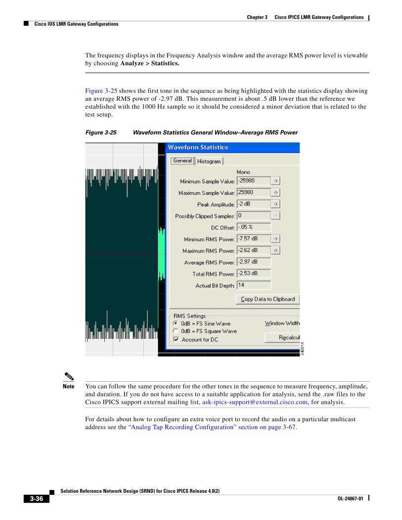
Chapter 3 Cisco IPICS LMR Gateway ConfigurationsCisco IOS LMR Gateway Configurations
The frequency displays in the Frequency Analysis window and the average RMS power level is viewable by choosing Analyze > Statistics.
Figure 3-25 shows the first tone in the sequence as being highlighted with the statistics display showing an average RMS power of -2.97 dB. This measurement is about .5 dB lower than the reference we established with the 1000 Hz sample so it should be considered a minor deviation that is related to the test setup.
Figure 3-25 Waveform Statistics General Window–Average RMS Power
Note You can follow the same procedure for the other tones in the sequence to measure frequency, amplitude, and duration. If you do not have access to a suitable application for analysis, send the .raw files to the Cisco IPICS support external mailing list, [email protected], for analysis.
For details about how to configure an extra voice port to record the audio on a particular multicast address see the “Analog Tap Recording Configuration” section on page 3-67.
3-36Solution Reference Network Design (SRND) for Cisco IPICS Release 4.0(2)
OL-24067-01
Chapter 3 Cisco IPICS LMR Gateway ConfigurationsCisco IOS LMR Gateway Configurations
IDC Caveats
Be aware of the following caveats, which pertain to the use of tone-controlled radio channels on the IDC in Cisco IPICS:
• The server configuration determines the order in which the IDC displays the radio channel selector buttons. There is currently no provision to enable reordering or sorting of these buttons.
• Each channel in a radio channel inherits the volume, spatial positioning, VAD, preferred codec, and RX mute during PTT settings from the radio channel. There is currently no provision to enable individual settings.
• The secure indicator is set based on the security setting of the radio channel itself and not on the individual channel selector buttons.
• The voice replay feature records and plays back any audio that is played out to the speakers across radio channels. That is, the voice replay feature records and plays back audio according to the channel that was tuned (active) at the time of capture. The voice replay feature does not track or provide indication of the channel that was active when the audio was received.
• In certain situations, performing one or more simultaneous operations on the same radio may result in unpredictable results.
– If two IDC users simultaneously attempt to change channels on the same radio, the radio may not change channels and transmissions may be mixed from other speaker(s), or the radio may change to a different channel than either of the channels that were selected.
– If an IDC user presses a channel selector button and another user presses a different channel selector button before the first user presses the PTT button to talk, the transmission may be sent over an unintended frequency if the first user does not reselect the channel selector button.
– If an IDC user begins to transmit while another user attempts to change channels on the same radio, transmission may occur in the channel that was selected by the second user. Or, the channel may not actually be changed but the tone control sequence sent by the attempted channel change may transmit. In this case, the IDC may incorrectly represent the channel that is currently selected.
– If an IDC user tries to change the active channel on the radio at the same time that a voice transmission is being received, the physical radio channel may not change, depending on network and radio configurations. However, because the IDC cannot detect if the radio channel actually changed, the IDC may incorrectly reflect that the channel has been changed even if it has not been changed. When the user next presses the PTT button, while no transmission is being received, the radio will tune to the channel that the user last selected.
– If a conflict causes the LMR gateway to not generate tones, even though IDC users are transmitting, the low level guard tone may not be present. In this situation, user transmissions may not flow over the radio network.
• Scan mode behavior on the IDC depends on the specific radio configuration. When you use the scan functionality and press the PTT button, the IDC may not be able to accurately detect the frequency that is currently tuned. In this case, the scan functionality may stop or continue and transmission may be sent over an unintended frequency.
• When you press a channel selector button, the function tone may change the state of one or more controls at the same time, depending on the configuration.
• When you connect the IDC by using SIP, radio functionality is limited because the RMS does not pass the RFC tones. In cases where the RMS is running a version of Cisco IOS software that supports the tone remote feature, and the default incoming dial peer (555) has been configured with the
3-37Solution Reference Network Design (SRND) for Cisco IPICS Release 4.0(2)
OL-24067-01
Chapter 3 Cisco IPICS LMR Gateway ConfigurationsCisco IOS LMR Gateway Configurations
required rtp payload-type commands, the RFC 2198 and RFC 2833 packets that are sent by IDC clients get translated by the RMS loopback interface into audible inband tones. These tones may cause the physical radio to retune.
• Intermixing SIP-based (remote) IDC users with local (multicast) users on the same radio may cause the following issues:
Note The behaviors that are listed below may depend on the following factors: • The version of Cisco IOS that the RMS is running and if that version supports the tone remote feature • Whether the default incoming dial peer (555) configuration that the IDC users to establish SIP calls to the RMS includes the required rtp payload-type commands. When the above conditions are met, remote IDC users send RFC 2198 and RFC 2833 packets via unicast to the RMS loopbacks, which results in the inband audio tones being sent out the other side of the loopback.
– Control and signaling tones that are normally not audible to multicast users may become audible to participants in VTGs and those who are connected remotely. This situation can cause some tones to play out for the entire duration of the audio.
– Controls that are sent inband because of an RMS loopback, which is used for communications between SIP multicast/VTGs, cannot be properly recognized by multicast users or other SIP users.
– Radio control tones can traverse radio channel VTGs and tune radios that they were not intended for.
– IDC clients that are in different locations (or the same location for SIP-based users) may not be able to properly reflect radio state changes.
– The IDC channel control and signal buttons do not change to reflect the currently selected channel. Therefore, a signal (such as a page) could be transmitted over an unintended channel.
– Radio controls that toggle by using the same tone sequence cannot be reliably detected because the starting or current state of the control cannot be determined.
– There is no correlation between radio controls and channel selection. That is, pressing a channel selector button on one radio is sent only to that radio.
Consider the flow of the RFC 2833 packets in a scenario that involves a remote IDC (10.10.10.5) and a local multicast IDC (10.10.1.2). The behavior in this scenario depends on these factors: the version of Cisco IOS that the RMS is running, and the incoming dial peer configuration that the remote IDC uses to establish SIP calls to the RMS.
• When the RMS is not running the required Cisco IOS software or the dial peer does not have the rtp payload-type commands, the RFC packets that the remote IDC sends to the RMS get dropped.
• When the required Cisco IOS software is running and the dial peer configuration is complete, the RMS injects the inband audio tones in the multicast stream that is sent to the LMR gateway and the multicast IDC user.
Although the tones can be used to control the radio, they may also be considered undesirable because all of the endpoints that monitor the multicast stream hear the audio tones. Therefore, make sure that you understand the various behaviors before you decide which one is most appropriate for your implementation.
3-38Solution Reference Network Design (SRND) for Cisco IPICS Release 4.0(2)
OL-24067-01
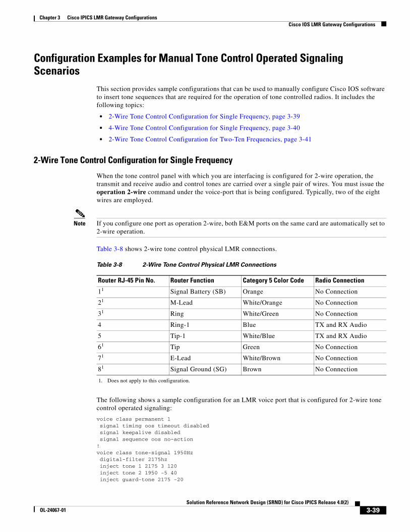
Chapter 3 Cisco IPICS LMR Gateway ConfigurationsCisco IOS LMR Gateway Configurations
Configuration Examples for Manual Tone Control Operated Signaling Scenarios
This section provides sample configurations that can be used to manually configure Cisco IOS software to insert tone sequences that are required for the operation of tone controlled radios. It includes the following topics:
• 2-Wire Tone Control Configuration for Single Frequency, page 3-39
• 4-Wire Tone Control Configuration for Single Frequency, page 3-40
• 2-Wire Tone Control Configuration for Two-Ten Frequencies, page 3-41
2-Wire Tone Control Configuration for Single Frequency
When the tone control panel with which you are interfacing is configured for 2-wire operation, the transmit and receive audio and control tones are carried over a single pair of wires. You must issue the operation 2-wire command under the voice-port that is being configured. Typically, two of the eight wires are employed.
Note If you configure one port as operation 2-wire, both E&M ports on the same card are automatically set to 2-wire operation.
Table 3-8 shows 2-wire tone control physical LMR connections.
The following shows a sample configuration for an LMR voice port that is configured for 2-wire tone control operated signaling:
voice class permanent 1 signal timing oos timeout disabled signal keepalive disabled signal sequence oos no-action!voice class tone-signal 1950Hz digital-filter 2175hz inject tone 1 2175 3 120 inject tone 2 1950 -5 40 inject guard-tone 2175 -20
Table 3-8 2-Wire Tone Control Physical LMR Connections
Router RJ-45 Pin No. Router Function Category 5 Color Code Radio Connection
11
1. Does not apply to this configuration.
Signal Battery (SB) Orange No Connection
21 M-Lead White/Orange No Connection
31 Ring White/Green No Connection
4 Ring-1 Blue TX and RX Audio
5 Tip-1 White/Blue TX and RX Audio
61 Tip Green No Connection
71 E-Lead White/Brown No Connection
81 Signal Ground (SG) Brown No Connection
3-39Solution Reference Network Design (SRND) for Cisco IPICS Release 4.0(2)
OL-24067-01
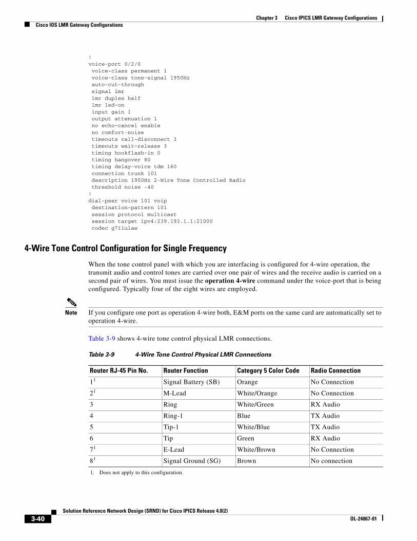
Chapter 3 Cisco IPICS LMR Gateway ConfigurationsCisco IOS LMR Gateway Configurations
!voice-port 0/2/0 voice-class permanent 1 voice-class tone-signal 1950Hz auto-cut-through signal lmr lmr duplex half lmr led-on input gain 1 output attenuation 1 no echo-cancel enable no comfort-noise timeouts call-disconnect 3 timeouts wait-release 3 timing hookflash-in 0 timing hangover 80 timing delay-voice tdm 160 connection trunk 101 description 1950Hz 2-Wire Tone Controlled Radio threshold noise -40!dial-peer voice 101 voip destination-pattern 101 session protocol multicast session target ipv4:239.193.1.1:21000 codec g711ulaw
4-Wire Tone Control Configuration for Single Frequency
When the tone control panel with which you are interfacing is configured for 4-wire operation, the transmit audio and control tones are carried over one pair of wires and the receive audio is carried on a second pair of wires. You must issue the operation 4-wire command under the voice-port that is being configured. Typically four of the eight wires are employed.
Note If you configure one port as operation 4-wire both, E&M ports on the same card are automatically set to operation 4-wire.
Table 3-9 shows 4-wire tone control physical LMR connections.
Table 3-9 4-Wire Tone Control Physical LMR Connections
Router RJ-45 Pin No. Router Function Category 5 Color Code Radio Connection
11
1. Does not apply to this configuration.
Signal Battery (SB) Orange No Connection
21 M-Lead White/Orange No Connection
3 Ring White/Green RX Audio
4 Ring-1 Blue TX Audio
5 Tip-1 White/Blue TX Audio
6 Tip Green RX Audio
71 E-Lead White/Brown No Connection
81 Signal Ground (SG) Brown No connection
3-40Solution Reference Network Design (SRND) for Cisco IPICS Release 4.0(2)
OL-24067-01
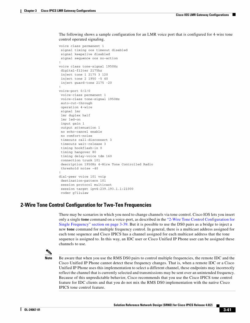
Chapter 3 Cisco IPICS LMR Gateway ConfigurationsCisco IOS LMR Gateway Configurations
The following shows a sample configuration for an LMR voice port that is configured for 4-wire tone control operated signaling.
voice class permanent 1 signal timing oos timeout disabled signal keepalive disabled signal sequence oos no-action!voice class tone-signal 1950Hz digital-filter 2175hz inject tone 1 2175 3 120 inject tone 2 1950 -5 40 inject guard-tone 2175 -20 !voice-port 0/2/0 voice-class permanent 1 voice-class tone-signal 1950Hz auto-cut-through operation 4-wire signal lmr lmr duplex half lmr led-on input gain 1 output attenuation 1 no echo-cancel enable no comfort-noise timeouts call-disconnect 3 timeouts wait-release 3 timing hookflash-in 0 timing hangover 80 timing delay-voice tdm 160 connection trunk 101 description 1950Hz 4-Wire Tone Controlled Radio threshold noise -40!dial-peer voice 101 voip destination-pattern 101 session protocol multicast session target ipv4:239.193.1.1:21000 codec g711ulaw
2-Wire Tone Control Configuration for Two-Ten Frequencies
There may be scenarios in which you need to change channels via tone control. Cisco IOS lets you insert only a single tone command on a voice-port, as described in the “2-Wire Tone Control Configuration for Single Frequency” section on page 3-39. But it is possible to use the DS0 pairs as a bridge to inject a new tone command for multiple frequency control. In general, there is a multicast address assigned for each tone sequence and Cisco IPICS has a channel assigned for each multicast address that the tone sequence is assigned to. In this way, an IDC user or Cisco Unified IP Phone user can be assigned these channels to use.
Note Be aware that when you use the RMS DS0 pairs to control multiple frequencies, the remote IDC and the Cisco Unified IP Phone cannot detect these frequency changes. That is, when a remote IDC or a Cisco Unified IP Phone uses this implementation to select a different channel, these endpoints may incorrectly reflect the channel that is currently selected and transmissions may be sent over an unintended frequency. Because of this unpredictable behavior, Cisco recommends that you use the Cisco IPICS tone control feature for IDC clients and that you do not mix the RMS DS0 implementation with the native Cisco IPICS tone control feature.
3-41Solution Reference Network Design (SRND) for Cisco IPICS Release 4.0(2)
OL-24067-01
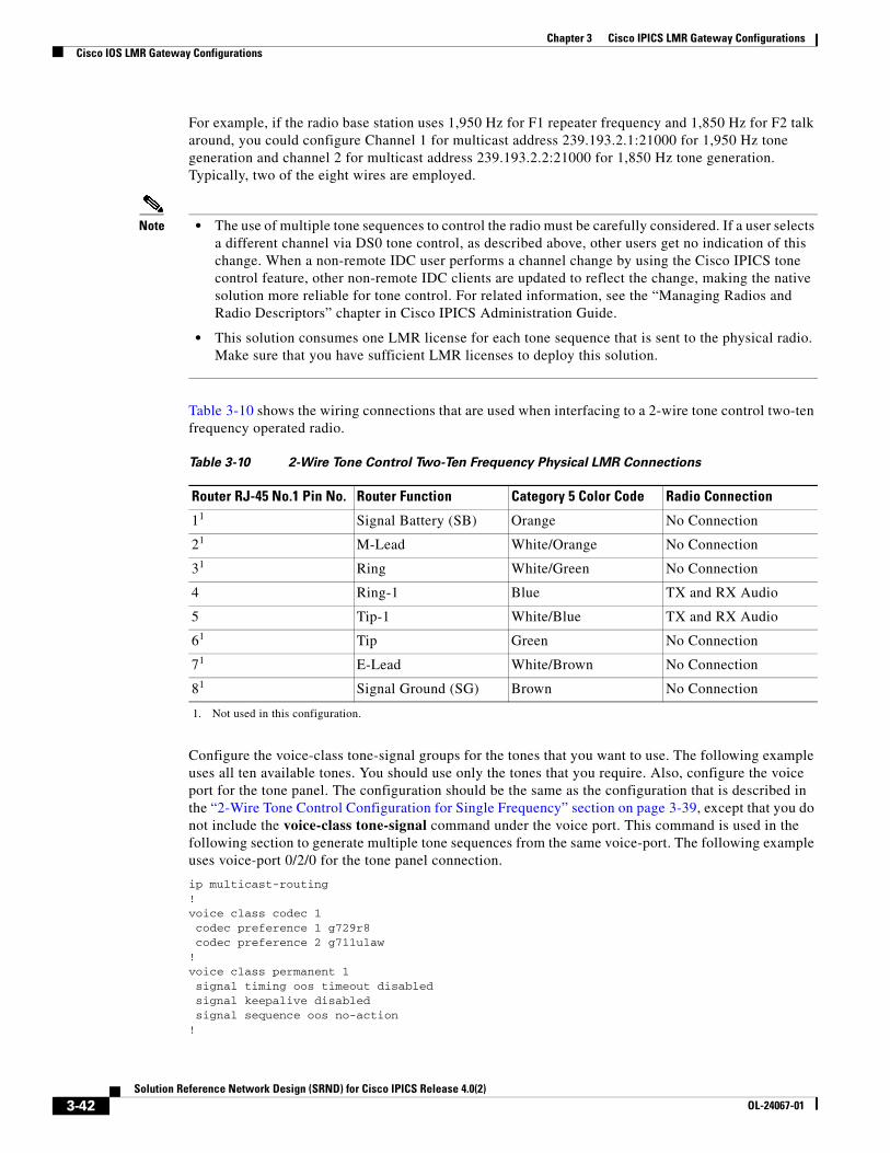
Chapter 3 Cisco IPICS LMR Gateway ConfigurationsCisco IOS LMR Gateway Configurations
For example, if the radio base station uses 1,950 Hz for F1 repeater frequency and 1,850 Hz for F2 talk around, you could configure Channel 1 for multicast address 239.193.2.1:21000 for 1,950 Hz tone generation and channel 2 for multicast address 239.193.2.2:21000 for 1,850 Hz tone generation. Typically, two of the eight wires are employed.
Note • The use of multiple tone sequences to control the radio must be carefully considered. If a user selects a different channel via DS0 tone control, as described above, other users get no indication of this change. When a non-remote IDC user performs a channel change by using the Cisco IPICS tone control feature, other non-remote IDC clients are updated to reflect the change, making the native solution more reliable for tone control. For related information, see the “Managing Radios and Radio Descriptors” chapter in Cisco IPICS Administration Guide.
• This solution consumes one LMR license for each tone sequence that is sent to the physical radio. Make sure that you have sufficient LMR licenses to deploy this solution.
Table 3-10 shows the wiring connections that are used when interfacing to a 2-wire tone control two-ten frequency operated radio.
Configure the voice-class tone-signal groups for the tones that you want to use. The following example uses all ten available tones. You should use only the tones that you require. Also, configure the voice port for the tone panel. The configuration should be the same as the configuration that is described in the “2-Wire Tone Control Configuration for Single Frequency” section on page 3-39, except that you do not include the voice-class tone-signal command under the voice port. This command is used in the following section to generate multiple tone sequences from the same voice-port. The following example uses voice-port 0/2/0 for the tone panel connection.
ip multicast-routing!voice class codec 1 codec preference 1 g729r8 codec preference 2 g711ulaw!voice class permanent 1 signal timing oos timeout disabled signal keepalive disabled signal sequence oos no-action!
Table 3-10 2-Wire Tone Control Two-Ten Frequency Physical LMR Connections
Router RJ-45 No.1 Pin No. Router Function Category 5 Color Code Radio Connection
11
1. Not used in this configuration.
Signal Battery (SB) Orange No Connection
21 M-Lead White/Orange No Connection
31 Ring White/Green No Connection
4 Ring-1 Blue TX and RX Audio
5 Tip-1 White/Blue TX and RX Audio
61 Tip Green No Connection
71 E-Lead White/Brown No Connection
81 Signal Ground (SG) Brown No Connection
3-42Solution Reference Network Design (SRND) for Cisco IPICS Release 4.0(2)
OL-24067-01

Chapter 3 Cisco IPICS LMR Gateway ConfigurationsCisco IOS LMR Gateway Configurations
voice class tone-signal 1950Hz digital-filter 2175hz inject tone 1 2175 3 120 inject tone 2 1950 -5 40 inject guard-tone 2175 -20 !voice class tone-signal 1850Hz digital-filter 2175hz inject tone 1 2175 3 120 inject tone 2 1850 -5 40 inject guard-tone 2175 -20!voice class tone-signal 1750Hz digital-filter 2175hz inject tone 1 2175 3 120 inject tone 2 1750 -5 40 inject guard-tone 2175 -20 !voice class tone-signal 1650Hz digital-filter 2175hz inject tone 1 2175 3 120 inject tone 2 1650 -5 40 inject guard-tone 2175 -20 !voice class tone-signal 1550Hz digital-filter 2175hz inject tone 1 2175 3 120 inject tone 2 1550 -5 40 inject guard-tone 2175 -20 !voice class tone-signal 1450Hz digital-filter 2175hz inject tone 1 2175 3 120 inject tone 2 1450 -5 40 inject guard-tone 2175 -20 !voice class tone-signal 1350Hz digital-filter 2175hz inject tone 1 2175 3 120 inject tone 2 1350 -5 40 inject guard-tone 2175 -20 !voice class tone-signal 1250Hz digital-filter 2175hz inject tone 1 2175 3 120 inject tone 2 1250 -5 40 inject guard-tone 2175 -20!voice class tone-signal 1150Hz digital-filter 2175hz inject tone 1 2175 3 120 inject tone 2 1150 -5 40 inject guard-tone 2175 -20 !voice class tone-signal 1050Hz digital-filter 2175hz inject tone 1 2175 3 120 inject tone 2 1050 -5 40 inject guard-tone 2175 -20 !interface Loopback0 ip address 192.168.4.6 255.255.255.255 ip pim sparse-dense-mode!
3-43Solution Reference Network Design (SRND) for Cisco IPICS Release 4.0(2)
OL-24067-01
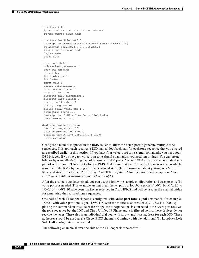
Chapter 3 Cisco IPICS LMR Gateway ConfigurationsCisco IOS LMR Gateway Configurations
interface Vif1 ip address 192.168.3.5 255.255.255.252 ip pim sparse-dense-mode!interface FastEthernet0/0 description $ETH-LAN$$ETH-SW-LAUNCH$$INTF-INFO-FE 0/0$ ip address 192.168.0.6 255.255.255.0 ip pim sparse-dense-mode duplex auto speed auto!voice-port 0/2/0 voice-class permanent 1 auto-cut-through signal lmr lmr duplex half lmr led-on input gain 1 output attenuation 1 no echo-cancel enable no comfort-noise timeouts call-disconnect 3 timeouts wait-release 3 timing hookflash-in 0 timing hangover 80 timing delay-voice tdm 160 connection trunk 101 description 2-Wire Tone Controlled Radio threshold noise -40!dial-peer voice 101 voip destination-pattern 101 session protocol multicast session target ipv4:239.193.1.1:21000 codec g711ulaw
Configure a manual loopback in the RMS router to allow the voice-port to generate multiple tone sequences. This approach requires a DS0 manual loopback pair for each tone sequence that you entered as described earlier in this section. If you have four voice-port tone-signal commands, you need four DS0 bridges. If you have ten voice-port tone-signal commands, you need ten bridges. You can create bridges by manually defining the voice ports with dial peers. You will likely use a voice port pair that is part of one of your T1 loopbacks for the RMS. Make sure that the T1 loopback pair is not an available resource in the RMS by putting it in the Reserved state. (For information about putting an RMS in Reserved state, refer to the “Performing Cisco IPICS System Administrator Tasks” chapter in Cisco IPICS Server Administration Guide, Release 4.0(2.)
After the channels are determined, you can use the following sample configuration and transpose the T1 voice ports as needed. This example assumes that the ten pairs of loopback ports of 1/0/0:1<->1/0/1:1 to 1/0/0:10<->1/0/1:10 have been marked as reserved in Cisco IPICS and will be used as the manual bridge for generating the required tone sequences.
One half of each T1 loopback pair is configured with voice-port tone-signal commands (for example, 1/0/0:1 with voice-port tone-signal 1,950 Hz) with the multicast address of 239.193.2.1:21000. By placing the command on this side of the bridge, the tone panel that is connected to the E&M port receives the tone sequence but the IDC and Cisco Unified IP Phone audio is filtered so that these devices do not receive the tones. There also is an individual dial peer with its own multicast address for each DS0. These addresses should be used as the Cisco IPICS channels. Continue with the additional T1 Loopback Left Side Half configurations as needed.
The following example shows one side of the T1 loopback tone control.
3-44Solution Reference Network Design (SRND) for Cisco IPICS Release 4.0(2)
OL-24067-01

Chapter 3 Cisco IPICS LMR Gateway ConfigurationsCisco IOS LMR Gateway Configurations
voice-port 1/0/0:1 voice-class permanent 1 voice-class tone-signal 1950Hz auto-cut-through lmr m-lead audio-gate-in lmr e-lead voice no echo-cancel enable no comfort-noise timeouts call-disconnect 3 timing hookflash-in 0 timing hangover 180 timing delay-voice tdm 180 connection trunk 1950101 description Tone Control 1950 IDC Bridge (Disabled in Cisco IPICS)!voice-port 1/0/0:2 voice-class permanent 1 voice-class tone-signal 1850Hz auto-cut-through lmr m-lead audio-gate-in lmr e-lead voice no echo-cancel enable no comfort-noise timeouts call-disconnect 3 timing hookflash-in 0 timing hangover 180 timing delay-voice tdm 180 connection trunk 1850101 description Tone Control 1850 IDC Bridge (Disabled in Cisco IPICS)!voice-port 1/0/0:3 voice-class permanent 1 voice-class tone-signal 1750Hz auto-cut-through lmr m-lead audio-gate-in lmr e-lead voice no echo-cancel enable no comfort-noise timeouts call-disconnect 3 timing hookflash-in 0 timing hangover 180 timing delay-voice tdm 180 connection trunk 1750101 description Tone Control 1750 IDC Bridge (Disabled in Cisco IPICS)!voice-port 1/0/0:4 voice-class permanent 1 voice-class tone-signal 1650Hz auto-cut-through lmr m-lead audio-gate-in lmr e-lead voice no echo-cancel enable no comfort-noise timeouts call-disconnect 3 timing hookflash-in 0 timing hangover 180 timing delay-voice tdm 180 connection trunk 1650101 description Tone Control 1650 IDC Bridge (Disabled in Cisco IPICS)!voice-port 1/0/0:5 voice-class permanent 1 voice-class tone-signal 1550Hz auto-cut-through
3-45Solution Reference Network Design (SRND) for Cisco IPICS Release 4.0(2)
OL-24067-01

Chapter 3 Cisco IPICS LMR Gateway ConfigurationsCisco IOS LMR Gateway Configurations
lmr m-lead audio-gate-in lmr e-lead voice no echo-cancel enable no comfort-noise timeouts call-disconnect 3 timing hookflash-in 0 timing hangover 180 timing delay-voice tdm 180 connection trunk 1550101 description Tone Control 1550 IDC Bridge (Disabled in Cisco IPICS)!voice-port 1/0/0:6 voice-class permanent 1 voice-class tone-signal 1450Hz auto-cut-through lmr m-lead audio-gate-in lmr e-lead voice no echo-cancel enable no comfort-noise timeouts call-disconnect 3 timing hookflash-in 0 timing hangover 180 timing delay-voice tdm 180 connection trunk 1450101 description Tone Control 1450 IDC Bridge (Disabled in Cisco IPICS)!voice-port 1/0/0:7 voice-class permanent 1 voice-class tone-signal 1350Hz auto-cut-through lmr m-lead audio-gate-in lmr e-lead voice no echo-cancel enable no comfort-noise timeouts call-disconnect 3 timing hookflash-in 0 timing hangover 180 timing delay-voice tdm 180 connection trunk 1350101 description Tone Control 1350 IDC Bridge (Disabled in Cisco IPICS)!voice-port 1/0/0:8 voice-class permanent 1 voice-class tone-signal 1250Hz auto-cut-through lmr m-lead audio-gate-in lmr e-lead voice no echo-cancel enable no comfort-noise timeouts call-disconnect 3 timing hookflash-in 0 timing hangover 180 timing delay-voice tdm 180 connection trunk 1250101 description Tone Control 1250 IDC Bridge (Disabled in Cisco IPICS)!voice-port 1/0/0:9 voice-class permanent 1 voice-class tone-signal 1150Hz auto-cut-through lmr m-lead audio-gate-in lmr e-lead voice no echo-cancel enable no comfort-noise
3-46Solution Reference Network Design (SRND) for Cisco IPICS Release 4.0(2)
OL-24067-01

Chapter 3 Cisco IPICS LMR Gateway ConfigurationsCisco IOS LMR Gateway Configurations
timeouts call-disconnect 3 timing hookflash-in 0 timing hangover 180 timing delay-voice tdm 180 connection trunk 1150101 description Tone Control 1150 IDC Bridge (Disabled in Cisco IPICS)!voice-port 1/0/0:10 voice-class permanent 1 voice-class tone-signal 1050Hz auto-cut-through lmr m-lead audio-gate-in lmr e-lead voice no echo-cancel enable no comfort-noise timeouts call-disconnect 3 timing hookflash-in 0 timing hangover 180 timing delay-voice tdm 180 connection trunk 1050101 description Tone Control 1050 IDC Bridge (Disabled in Cisco IPICS)!dial-peer voice 1950101 voip description Tone Control 1950 IDC Bridge destination-pattern 1950101 session protocol multicast session target ipv4:239.193.2.1:21000 codec g711ulaw no vad!dial-peer voice 1850101 voip description Tone Control 1850 IDC Bridge destination-pattern 1850101 session protocol multicast session target ipv4:239.193.2.2:21000 codec g711ulaw no vad!dial-peer voice 1750101 voip description Tone Control 1750 IDC Bridge destination-pattern 1750101 session protocol multicast session target ipv4:239.193.2.3:21000 codec g711ulaw no vad!dial-peer voice 1650101 voip description Tone Control 1650 IDC Bridge destination-pattern 1650101 session protocol multicast session target ipv4:239.193.2.4:21000 codec g711ulaw no vad!dial-peer voice 1550101 voip description Tone Control 1550 IDC Bridge destination-pattern 1550101 session protocol multicast session target ipv4:239.193.2.5:21000 codec g711ulaw no vad!dial-peer voice 1450101 voip description Tone Control 1450 IDC Bridge
3-47Solution Reference Network Design (SRND) for Cisco IPICS Release 4.0(2)
OL-24067-01

Chapter 3 Cisco IPICS LMR Gateway ConfigurationsCisco IOS LMR Gateway Configurations
destination-pattern 1450101 session protocol multicast session target ipv4:239.193.2.6:21000 codec g711ulaw no vad!dial-peer voice 1350101 voip description Tone Control 1350 IDC Bridge destination-pattern 1350101 session protocol multicast session target ipv4:239.193.2.7:21000 codec g711ulaw no vad!dial-peer voice 1250101 voip description Tone Control 1250 IDC Bridge destination-pattern 1250101 session protocol multicast session target ipv4:239.193.2.8:21000 codec g711ulaw no vad!dial-peer voice 1150101 voip description Tone Control 1150 IDC Bridge destination-pattern 1150101 session protocol multicast session target ipv4:239.193.2.9:21000 codec g711ulaw no vad!dial-peer voice 1050101 voip description Tone Control 1050 IDC Bridge destination-pattern 1050101 session protocol multicast session target ipv4:239.193.2.10:21000 codec g711ulaw no vad
To simplify the concept of a T1 loopback, which joins two T1 interface ports, we refer to the two sides as right and left. In the following example, the right side of each configured T1 loopback pair (for example, 1/0/1:1 to 1/0/1:10) are all configured with the same multicast address as the dial peer that is assigned to voice-port 0/2/0. In this example, the address is 239.193.1.1:21000.
voice-port 1/0/1:1 voice-class permanent 1 auto-cut-through lmr m-lead audio-gate-in lmr e-lead voice no echo-cancel enable no comfort-noise timeouts call-disconnect 3 timing hookflash-in 0 timing hangover 80 connection trunk 2101 description Tone Control 1950 Radio Bridge (Disabled in Cisco IPICS)!voice-port 1/0/1:2 voice-class permanent 1 auto-cut-through lmr m-lead audio-gate-in lmr e-lead voice no echo-cancel enable no comfort-noise
3-48Solution Reference Network Design (SRND) for Cisco IPICS Release 4.0(2)
OL-24067-01

Chapter 3 Cisco IPICS LMR Gateway ConfigurationsCisco IOS LMR Gateway Configurations
timeouts call-disconnect 3 timing hookflash-in 0 timing hangover 80 connection trunk 2101 description Tone Control 1850 Radio Bridge (Disabled in Cisco IPICS)!voice-port 1/0/1:3 voice-class permanent 1 auto-cut-through lmr m-lead audio-gate-in lmr e-lead voice no echo-cancel enable no comfort-noise timeouts call-disconnect 3 timing hookflash-in 0 timing hangover 80 connection trunk 2101 description Tone Control 1750 Radio Bridge (Disabled in Cisco IPICS)!voice-port 1/0/1:4 voice-class permanent 1 auto-cut-through lmr m-lead audio-gate-in lmr e-lead voice no echo-cancel enable no comfort-noise timeouts call-disconnect 3 timing hookflash-in 0 timing hangover 80 connection trunk 2101 description Tone Control 1650 Radio Bridge (Disabled in Cisco IPICS)!voice-port 1/0/1:5 voice-class permanent 1 auto-cut-through lmr m-lead audio-gate-in lmr e-lead voice no echo-cancel enable no comfort-noise timeouts call-disconnect 3 timing hookflash-in 0 timing hangover 80 connection trunk 2101 description Tone Control 1550 Radio Bridge (Disabled in Cisco IPICS)!voice-port 1/0/1:6 voice-class permanent 1 auto-cut-through lmr m-lead audio-gate-in lmr e-lead voice no echo-cancel enable no comfort-noise timeouts call-disconnect 3 timing hookflash-in 0 timing hangover 80 connection trunk 2101 description Tone Control 1450 Radio Bridge (Disabled in Cisco IPICS)!voice-port 1/0/1:7 voice-class permanent 1 auto-cut-through lmr m-lead audio-gate-in lmr e-lead voice no echo-cancel enable
3-49Solution Reference Network Design (SRND) for Cisco IPICS Release 4.0(2)
OL-24067-01
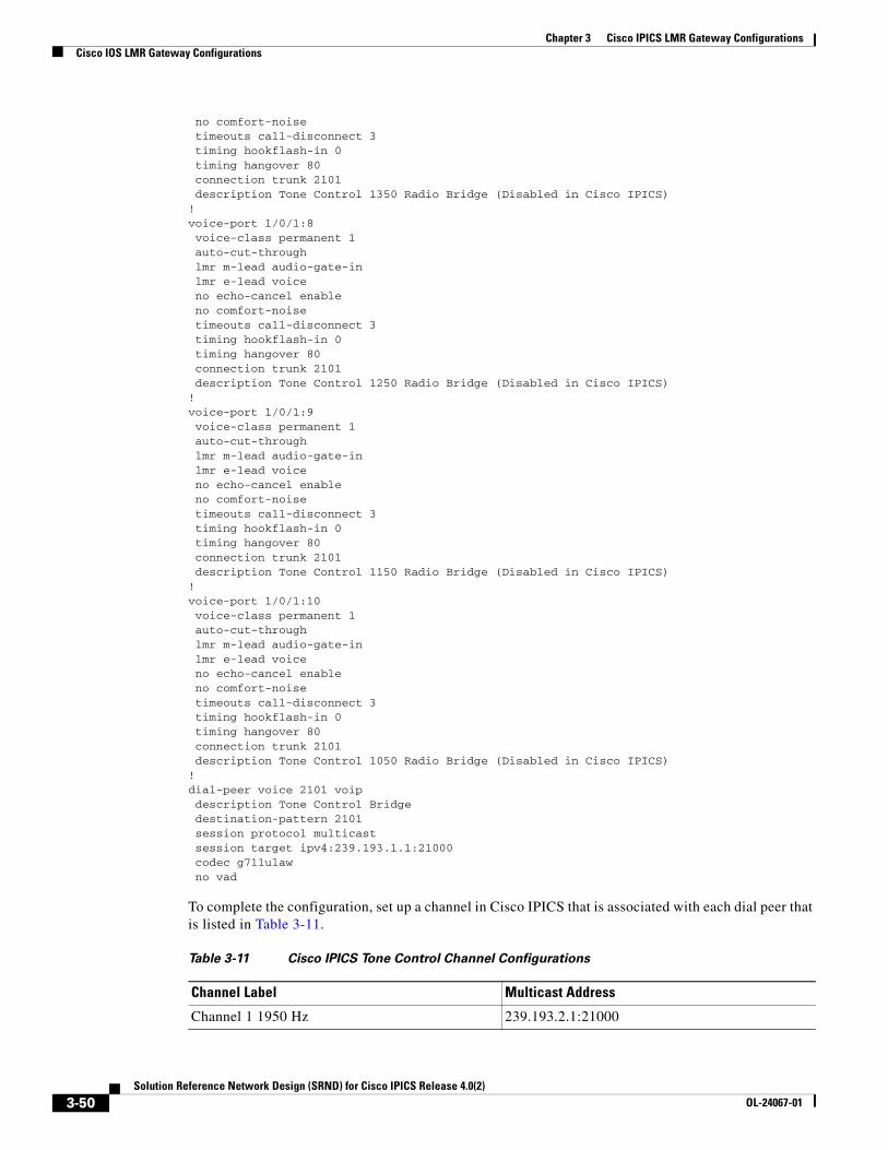
Chapter 3 Cisco IPICS LMR Gateway ConfigurationsCisco IOS LMR Gateway Configurations
no comfort-noise timeouts call-disconnect 3 timing hookflash-in 0 timing hangover 80 connection trunk 2101 description Tone Control 1350 Radio Bridge (Disabled in Cisco IPICS)!voice-port 1/0/1:8 voice-class permanent 1 auto-cut-through lmr m-lead audio-gate-in lmr e-lead voice no echo-cancel enable no comfort-noise timeouts call-disconnect 3 timing hookflash-in 0 timing hangover 80 connection trunk 2101 description Tone Control 1250 Radio Bridge (Disabled in Cisco IPICS)!voice-port 1/0/1:9 voice-class permanent 1 auto-cut-through lmr m-lead audio-gate-in lmr e-lead voice no echo-cancel enable no comfort-noise timeouts call-disconnect 3 timing hookflash-in 0 timing hangover 80 connection trunk 2101 description Tone Control 1150 Radio Bridge (Disabled in Cisco IPICS)!voice-port 1/0/1:10 voice-class permanent 1 auto-cut-through lmr m-lead audio-gate-in lmr e-lead voice no echo-cancel enable no comfort-noise timeouts call-disconnect 3 timing hookflash-in 0 timing hangover 80 connection trunk 2101 description Tone Control 1050 Radio Bridge (Disabled in Cisco IPICS)!dial-peer voice 2101 voip description Tone Control Bridge destination-pattern 2101 session protocol multicast session target ipv4:239.193.1.1:21000 codec g711ulaw no vad
To complete the configuration, set up a channel in Cisco IPICS that is associated with each dial peer that is listed in Table 3-11.
Table 3-11 Cisco IPICS Tone Control Channel Configurations
Channel Label Multicast Address
Channel 1 1950 Hz 239.193.2.1:21000
3-50Solution Reference Network Design (SRND) for Cisco IPICS Release 4.0(2)
OL-24067-01
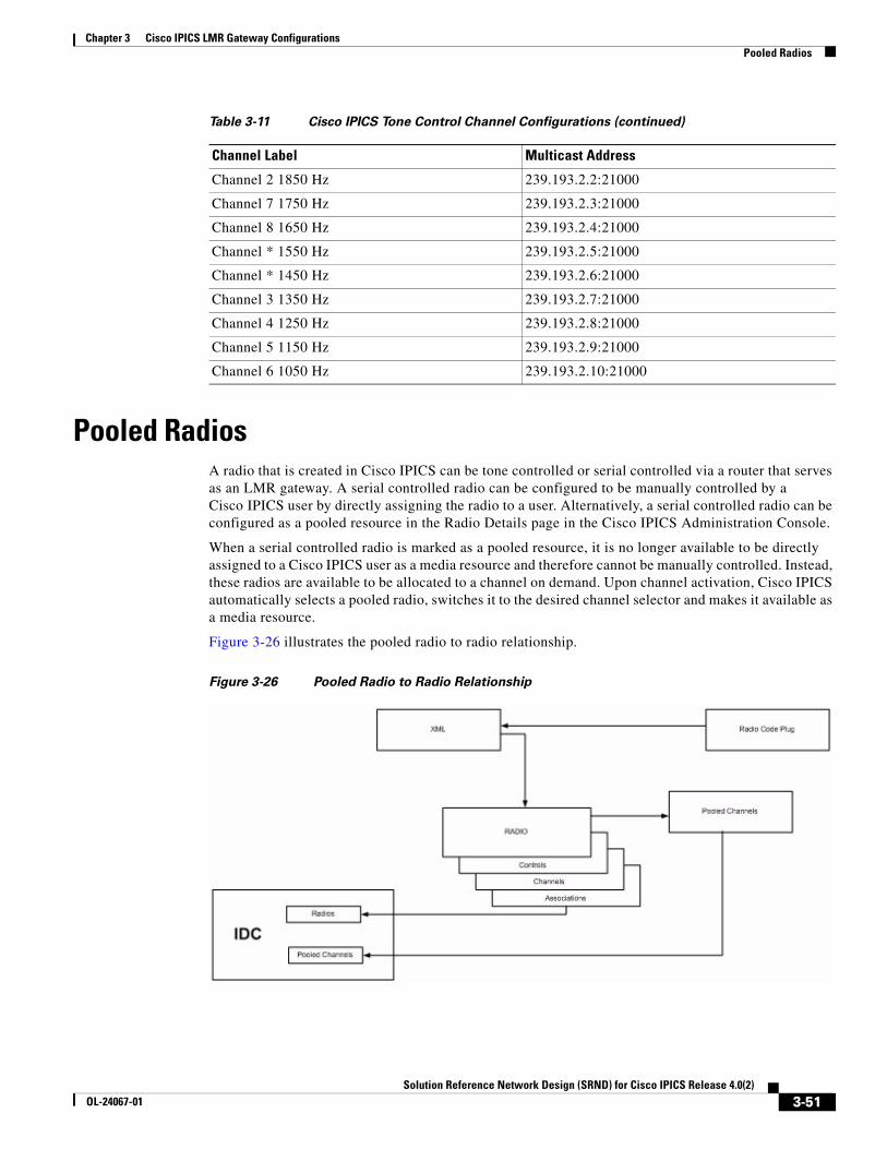
Chapter 3 Cisco IPICS LMR Gateway ConfigurationsPooled Radios
Pooled RadiosA radio that is created in Cisco IPICS can be tone controlled or serial controlled via a router that serves as an LMR gateway. A serial controlled radio can be configured to be manually controlled by a Cisco IPICS user by directly assigning the radio to a user. Alternatively, a serial controlled radio can be configured as a pooled resource in the Radio Details page in the Cisco IPICS Administration Console.
When a serial controlled radio is marked as a pooled resource, it is no longer available to be directly assigned to a Cisco IPICS user as a media resource and therefore cannot be manually controlled. Instead, these radios are available to be allocated to a channel on demand. Upon channel activation, Cisco IPICS automatically selects a pooled radio, switches it to the desired channel selector and makes it available as a media resource.
Figure 3-26 illustrates the pooled radio to radio relationship.
Figure 3-26 Pooled Radio to Radio Relationship
Channel 2 1850 Hz 239.193.2.2:21000
Channel 7 1750 Hz 239.193.2.3:21000
Channel 8 1650 Hz 239.193.2.4:21000
Channel * 1550 Hz 239.193.2.5:21000
Channel * 1450 Hz 239.193.2.6:21000
Channel 3 1350 Hz 239.193.2.7:21000
Channel 4 1250 Hz 239.193.2.8:21000
Channel 5 1150 Hz 239.193.2.9:21000
Channel 6 1050 Hz 239.193.2.10:21000
Table 3-11 Cisco IPICS Tone Control Channel Configurations (continued)
Channel Label Multicast Address
3-51Solution Reference Network Design (SRND) for Cisco IPICS Release 4.0(2)
OL-24067-01
Chapter 3 Cisco IPICS LMR Gateway ConfigurationsPooled Radios
Using pooled resources reduces the complexity of a system and the training required to use it, improves efficiency, and reduces conflicts when sharing resources between agencies or dispatchers. Using pooled resources also increase system reliability: if a radio in the pool fails, other radios remain available to access the desired resource and the system allocates these resources automatically.
Pooled radios provide a different way of addressing resources than a manually controlled shared radio. With shared radios, you first need to selected shared radio, then change the radio channel selector to the desired talk group. With pooled radios, you select the desired talk group, which comes from a pool of radios that have multiple channels and talk groups associated with them. The the Cisco IPICS server automatically determines which radio is not busy, which has the resource available, and which has the highest priority for that use. With pooled radios, a system can be configured and tuned so that radios are automatically selected based on tower location, available bandwidth, and other criteria.
Configuring and Allocating Pooled ResourcesTo use channels from multiple pooled radios, each radio must be defined with the same XML descriptor. The XML descriptor defines the channel name and which “Zone” and “Selector” are associated with the channel that is programmed into the radio. The channel is programmed into the radio via a configuration file, called a code plug, that is uploaded to the radio.
Pools of radios are not explicitly maintained within Cisco IPICS. All pooled radios that are associated with a specific radio descriptor are considered to implicitly belong to that pool. This approach eliminates the need to manage pools of radios. Radios with a similar set of channel selectors as determined by a radio descriptor have similar characteristics and therefore belong to the same pool. If you need to ensure separation of radios between pools, use a different radio descriptor for each pool.
When you create a channel in the Cisco IPICS Administration Console, the Pooled Radio media type is available. When adding a pooled radio media connection, you must select a radio descriptor and a channel selector. The radio descriptor defines the pool of radios, and the channel selector instructs Cisco IPICS to set the allocated pooled radio to this channel when the channel is activated.
A pooled radios is allocated to a channel when the channel is activated. Channel activation can occur when a channel with a pooled radio is a member of a VTG and the VTG is activated, or when a channel with a pooled radio is activated by an IDC user.
Pooled Resource AllocationWhen a channel that has a pooled radio assigned to it is activated, Cisco IPICS searches for radio that are associated with the radio descriptor file in the media connection that is assigned to the channel. If Cisco IPICS finds a radio that is available and that meets these criteria, Cisco IPICS configures the radio to switch to the appropriate channel, group, or private call as described in the channel selector. After this process is completed, the radio is marked as allocated to the channel.
IPICS keeps track of a pooled radio allocation to a channel, including all channel activations that occurred via a VTG or an IDC user. When the last VTG or IDC deactivates the channel, IPICS automatically deallocate the pooled radio, and the radio becomes available for use for a future allocation. Until such a deallocation occurs, another activation of the same channel results in the use of the same pooled radio.
Note If a channel is created with a pooled radio connection and a multicast connection, Cisco IPICS always uses the cheaper media type. In this case, a multicast media connection is cheaper, therefore a pooled radio will never be allocated to this channel.
3-52Solution Reference Network Design (SRND) for Cisco IPICS Release 4.0(2)
OL-24067-01
Chapter 3 Cisco IPICS LMR Gateway ConfigurationsSerial Radio Control
IP phone and dial-in users cannot activate a pooled resource in Cisco IPICS. Therefore, an IP phone or dial-in cannot join a pooled radio channel if the channel is not already active.
Determining How many Pooled Radios to ConfigureThe main criteria to determine how many pooled radio resource to deploy for a given radio descriptor is the number of expected concurrent active channels. If the end user has 100 channel selectors available in a radio descriptor, but they don't expect to use more than say 10 channels at any given time, then they should deploy no less than 10 pooled radios for that radio descriptor.
Troubleshooting Channel Activation Failures
When a channel containing a pooled radio media connection cannot be activated, it could be because of the following reasons:
• There are no pooled radios belonging to the selected radio descriptor.
• The desired channel selector for all remaining pooled radios belonging to the selected radio descriptor is not enabled.
• All remaining pooled radios that belong to the selected radio descriptor are disabled or not CONNECTED_ONLINE.
• All pooled radios have already been allocated to other channels.
Optimizing Priorities for Trunked Networks and Wide Area SystemsIn a trunk system multisite deployment, there are always more talk groups defined than bearer channels available. To prevent a substantial number of collisions and busy conditions, a system design should attempt to optimize the trunk system utilization by allocating talk groups that are related geographically.
You perform the prioritization configuration process from the Cisco IPICS Administration Console by performing the following general steps. For related information, see the “Managing Radios and Radio Descriptors” chapter in Cisco IPICS Server Administration Guide.
1. To designate a radio as a pooled resource, choose the Server drawer, then choose Configuration > Radios > radio_name, then check the Pooled Resource check box in the in the General tab.
2. To set priorities for each channel in the radio, choose the Selectors tab for the radio. This tab shows each channel that is defined in the descriptor file for the radio. Check the Enabled check box and set the priority for each channel in the radio based on the system design and donor radio placement in the network.
After you complete this configuration, the pooled resource is available for use in a VTG.
Serial Radio ControlCisco IPICS provides the serial radio control feature, which supports the following serially controlled radios:
• EF Johnson 5300 and 5300ES mobile radios
• Sprint Nextel (iDEN) i355 handsets
3-53Solution Reference Network Design (SRND) for Cisco IPICS Release 4.0(2)
OL-24067-01
Chapter 3 Cisco IPICS LMR Gateway ConfigurationsSerial Radio Control
The serial radio control feature allows you to remotely control functions in a donor serial radio from the Cisco IPICS Administration Console or from the Cisco IPICS IDC. A donor radio allows sending and receiving audio between Cisco IPICS and a radio system. Functions that can be controlled include secure transmit mode, scan, monitor, channel/talkgroup change, and individual (unit-to-unit) calls and dynamic group calls, depending on the capabilities of the donor radio. Cisco IPICS also can detect changes in radio state, including talker ID and emergency “man down” alarms. This capability provides enhanced interoperability to Motorola SmartNet/SmartZone, P25, and Sprint Nextel (iDEN) radio networks.
When you set up serial control for a radio, you configure voice interoperability, which enables audio to pass between Cisco IPICS and a radio network via the E&M port on an LMR gateway. You also configure serial radio control for one of the following methods:
• Auxiliary port control—Used to control one radio that is attached an LMR gateway
• 8-port WAN interface card control—Used to control up to 8 radios that are attached an LMR gateway
• 16-port WAN interface card control—Used to control up to 16 radios that are attached an LMR gateway
This chapter includes these topics:
• Setting up and Configuring Serial Control for EF Johnson Radios, page 3-54
• Setting up and Configuring Serial Control for Sprint Nextel (iDEN) Handsets, page 3-58
Setting up and Configuring Serial Control for EF Johnson RadiosThe following sections explain how to connect and configure an EF Johnson 5300 or 5300ES mobile radio as a donor radio. This process involves these general steps:
1. Connect a donor radio. For detailed instructions, see the “Connecting an EF Johnson Donor Radio to an LMR Gateway” procedure on page 3-55.
2. Configure the LMR gateway. For detailed instructions, see the “Configuring the LMR Gateway for E&M Communications with EF Johnson Radios” section on page 3-56 and the “Configuring the LMR Gateway for Serial Radio Control” section on page 3-57
In addition, you must add the radio to Cisco IPICS and perform other tasks to allow serial control of the radio by Cisco IPICS. For detailed instructions, see Cisco IPICS Server Administration Guide, Release 2.2.
Required Components
You need the following components to set up and configure serial control for EF Johnson radios:
• Donor Radio—EF Johnson model 5300 mobile radio running firmware version 04.14.03 or later or model 5300ES running firmware version 06.08.08 or later
• LMR gateway—Cisco 2811 or 3845 with E&M ports
For voice interoperability:
• Cable for remote control head or fixed control station applications (EF Johnson part # 597-2002-249). One cable is required for each radio that you will connect.
• DB15 male to RJ-45 female adapter for connecting the control head cable to the LMR gateway E&M port (available from networked radio.com, part # REM-4496). One adapter is required for each radio that you will connect.
3-54Solution Reference Network Design (SRND) for Cisco IPICS Release 4.0(2)
OL-24067-01
Chapter 3 Cisco IPICS LMR Gateway ConfigurationsSerial Radio Control
• E&M cable—Category 5 straight-through Ethernet cable.
For serial radio control:
• 5300 Series Remote Programming Interface (RPI)—Includes a ribbon cable with a hirose connector, and a DB9 RS-232 connector (EF Johnson part # 023-5300-001). One RPE is required for each radio that you will connect.
• DB9 male to RJ-45 cable adapter (available from various third-party vendors). One adapter is required for each radio that you will connect.
• Category 5 straight-through Ethernet cable—Required only for auxiliary port control.
• Cisco “octopus” cable (Cisco part # 72-4023-01 or CAB-HD8-ASYNC)—One cable is required for 8-port WAN interface card control; two cables are required for 16-port WAN interface card control.
• Cisco 1800/2800/3800 series 8-port asynchronous high-speed WAN interface card model HWIC-8A—Required only for 8-port WAN interface card control.
• Cisco 1800/2800/3800 series 16-port asynchronous high-speed WAN interface card model HWIC-16A—Required only for 16-port WAN interface card control.
Connecting an EF Johnson Donor Radio to an LMR Gateway
To connect an EF Johnson 5300 or 5300ES mobile radio to an LMR gateway, follow these steps:
Procedure
Step 1 Make the connection for voice interoperability as follows:
a. Connect the E&M cable from an available port on the LMR gateway to the DB15 male to RJ-45 cable adapter.
b. Connect the radio control head cable, which is attached to the radio, to this adapter.
Step 2 Make the appropriate connections for serial radio control as follows:
• If you are setting up auxiliary port control, connect the category 5 straight-through Ethernet cable from the auxiliary port on the LMR gateway to the RJ-45 port on the RPI, using the DB9 male to RJ-45 data cable adapter.
• If you are setting up 8-port WAN interface card control, take these actions:
a. Connect the octopus cable to the WAN interface card.
b. Connect one of the lines on the octopus cable to the DB9 to RJ-45 cable adapter.
• If you are setting up 16-port WAN interface card control, take these actions:
a. Connect two octopus cables to the two ports on the WAN interface card.
b. Connect one of the lines on the octopus cable to the DB9 to RJ-45 cable adapter.
Step 3 Connect the DB9 to RJ45 cable adapter to the DB9 port on the RPI.
Step 4 Connect the ribbon cable from the RPI to the mic port on the radio.
3-55Solution Reference Network Design (SRND) for Cisco IPICS Release 4.0(2)
OL-24067-01
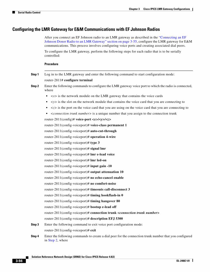
Chapter 3 Cisco IPICS LMR Gateway ConfigurationsSerial Radio Control
Configuring the LMR Gateway for E&M Communications with EF Johnson Radios
After you connect an EF Johnson radio to an LMR gateway as described in the “Connecting an EF Johnson Donor Radio to an LMR Gateway” section on page 3-55, configure the LMR gateway for E&M communications. This process involves configuring voice ports and creating associated dial peers.
To configure the LMR gateway, perform the following steps for each radio that is to be serially controlled:
Procedure
Step 1 Log in to the LMR gateway and enter the following command to start configuration mode:
router-2811# configure terminal
Step 2 Enter the following commands to configure the LMR gateway voice port to which the radio is connected, where
• <x> is the network module on the LMR gateway that contains the voice cards
• <y> is the slot on the network module that contains the voice card that you are connecting to
• <z> is the port on the voice card that you are using on the voice card that you are connecting to
• <connection trunk number> is a unique number that you assign to the connection trunk
router-2811(config)# voice-port <x>/<y>/<z>
router-2811(config-voiceport)# voice-class permanent 1
router-2811(config-voiceport)# auto-cut-through
router-2811(config-voiceport)# operation 4-wire
router-2811(config-voiceport)# type 3
router-2811(config-voiceport)# signal lmr
router-2811(config-voiceport)# lmr e-lead voice
router-2811(config-voiceport)# lmr led-on
router-2811(config-voiceport)# input gain -10
router-2811(config-voiceport)# output attenuation 10
router-2811(config-voiceport)# no echo-cancel enable
router-2811(config-voiceport)# no comfort-noise
router-2811(config-voiceport)# timeouts call-disconnect 3
router-2811(config-voiceport)# timing hookflash-in 0
router-2811(config-voiceport)# timing hangover 80
router-2811(config-voiceport)# bootup e-lead off
router-2811(config-voiceport)# connection trunk <connection trunk number>
router-2811(config-voiceport)# description EFJ 5300
Step 3 Enter the following command to exit voice port configuration mode:
router-2811(config-voiceport)# exit
Step 4 Enter the following commands to create a dial peer for the connection trunk number that you configured in Step 2, where
3-56Solution Reference Network Design (SRND) for Cisco IPICS Release 4.0(2)
OL-24067-01
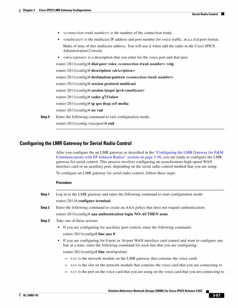
Chapter 3 Cisco IPICS LMR Gateway ConfigurationsSerial Radio Control
• <connection trunk number> is the number of the connection trunk.
• <multicast> is the multicast IP address and port number for voice traffic, in a.c.b.d:port format.
Make of note of this multicast address. You will use it when add the radio in the Cisco IPICS Administration Console.
• <description> is a description that you enter for the voice port and dial peer.
router-2811(config)# dial-peer voice <connection trunk number> voip
router-2811(config)# description <description>
router-2811(config)# destination-pattern <connection trunk number>
router-2811(config)# session protocol multicast
router-2811(config)# session target ipv4:<multicast>
router-2811(config)# codec g711ulaw
router-2811(config)# ip qos dscp cs5 media
router-2811(config)# no vad
Step 5 Enter the following command to exit configuration mode:
router-2811(config-voiceport)# end
Configuring the LMR Gateway for Serial Radio Control
After you configure the an LMR gateway as described in the “Configuring the LMR Gateway for E&M Communications with EF Johnson Radios” section on page 3-56, you are ready to configure the LMR gateway for serial control. This process involves configuring an asynchronous high-speed WAN interface card or an auxiliary port, depending on the serial radio control method that you are using.
To configure an LMR gateway for serial radio control, follow these steps:
Procedure
Step 1 Log in to the LMR gateway and enter the following command to start configuration mode:
router-2811# configure terminal
Step 2 Enter the following command to create an AAA policy that does not require authentication:
router-2811(config)# aaa authentication login NO-AUTHEN none
Step 3 Take one of these actions:
• If you are configuring for auxiliary port control, enter the following command:
router-2811(config)# line aux 0
• If you are configuring for 8-port or 16-port WAN interface card control and want to configure one line at a time, enter the following command for each line that you are configuring:
router-2811(config)# line <x>/<y>/<z>
– <x> is the network module on the LMR gateway that contains the voice cards
– <y> is the slot on the network module that contains the voice card that you are connecting to
– <z> is the port on the voice card that you are using on the voice card that you are connecting to
3-57Solution Reference Network Design (SRND) for Cisco IPICS Release 4.0(2)
OL-24067-01
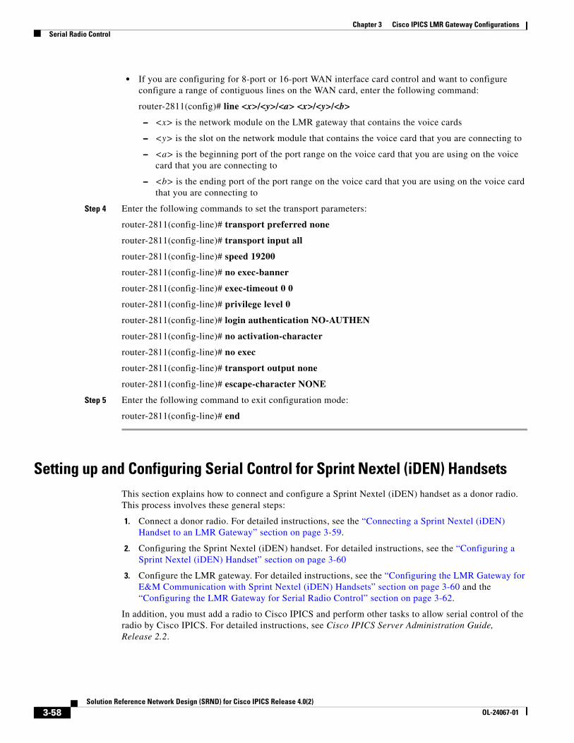
Chapter 3 Cisco IPICS LMR Gateway ConfigurationsSerial Radio Control
• If you are configuring for 8-port or 16-port WAN interface card control and want to configure configure a range of contiguous lines on the WAN card, enter the following command:
router-2811(config)# line <x>/<y>/<a> <x>/<y>/<b>
– <x> is the network module on the LMR gateway that contains the voice cards
– <y> is the slot on the network module that contains the voice card that you are connecting to
– <a> is the beginning port of the port range on the voice card that you are using on the voice card that you are connecting to
– <b> is the ending port of the port range on the voice card that you are using on the voice card that you are connecting to
Step 4 Enter the following commands to set the transport parameters:
router-2811(config-line)# transport preferred none
router-2811(config-line)# transport input all
router-2811(config-line)# speed 19200
router-2811(config-line)# no exec-banner
router-2811(config-line)# exec-timeout 0 0
router-2811(config-line)# privilege level 0
router-2811(config-line)# login authentication NO-AUTHEN
router-2811(config-line)# no activation-character
router-2811(config-line)# no exec
router-2811(config-line)# transport output none
router-2811(config-line)# escape-character NONE
Step 5 Enter the following command to exit configuration mode:
router-2811(config-line)# end
Setting up and Configuring Serial Control for Sprint Nextel (iDEN) HandsetsThis section explains how to connect and configure a Sprint Nextel (iDEN) handset as a donor radio. This process involves these general steps:
1. Connect a donor radio. For detailed instructions, see the “Connecting a Sprint Nextel (iDEN) Handset to an LMR Gateway” section on page 3-59.
2. Configuring the Sprint Nextel (iDEN) handset. For detailed instructions, see the “Configuring a Sprint Nextel (iDEN) Handset” section on page 3-60
3. Configure the LMR gateway. For detailed instructions, see the “Configuring the LMR Gateway for E&M Communication with Sprint Nextel (iDEN) Handsets” section on page 3-60 and the “Configuring the LMR Gateway for Serial Radio Control” section on page 3-62.
In addition, you must add a radio to Cisco IPICS and perform other tasks to allow serial control of the radio by Cisco IPICS. For detailed instructions, see Cisco IPICS Server Administration Guide, Release 2.2.
3-58Solution Reference Network Design (SRND) for Cisco IPICS Release 4.0(2)
OL-24067-01
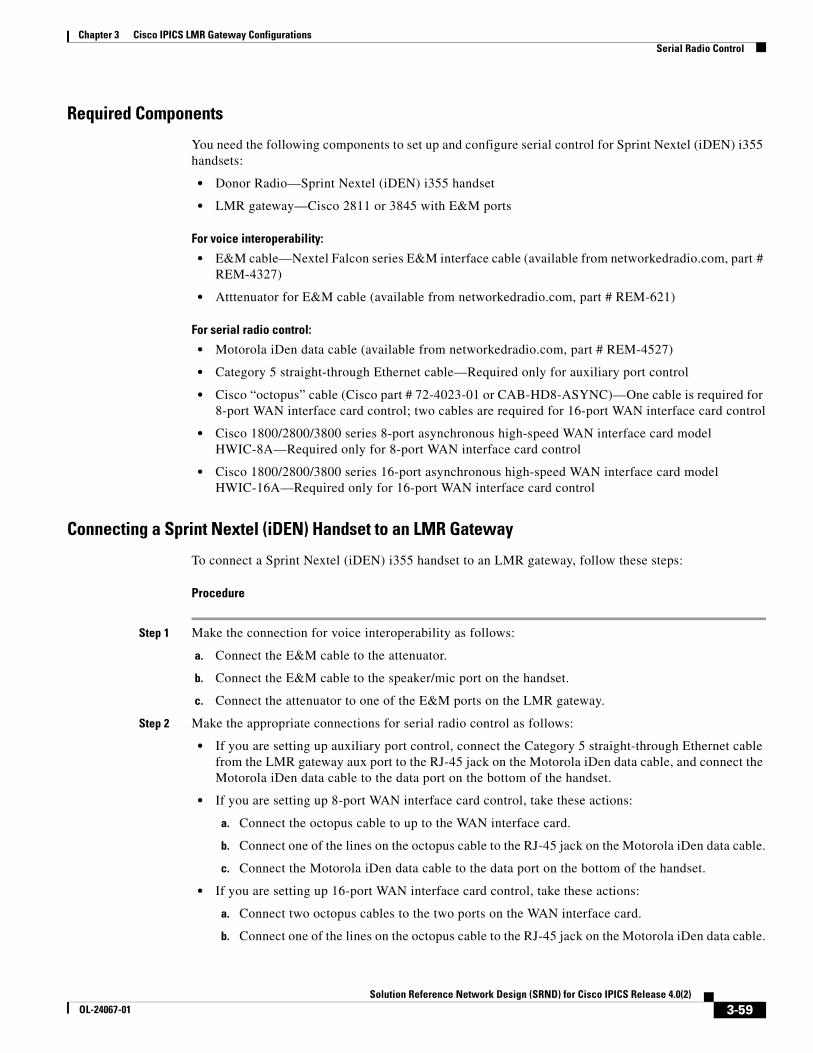
Chapter 3 Cisco IPICS LMR Gateway ConfigurationsSerial Radio Control
Required Components
You need the following components to set up and configure serial control for Sprint Nextel (iDEN) i355 handsets:
• Donor Radio—Sprint Nextel (iDEN) i355 handset
• LMR gateway—Cisco 2811 or 3845 with E&M ports
For voice interoperability:
• E&M cable—Nextel Falcon series E&M interface cable (available from networkedradio.com, part # REM-4327)
• Atttenuator for E&M cable (available from networkedradio.com, part # REM-621)
For serial radio control:
• Motorola iDen data cable (available from networkedradio.com, part # REM-4527)
• Category 5 straight-through Ethernet cable—Required only for auxiliary port control
• Cisco “octopus” cable (Cisco part # 72-4023-01 or CAB-HD8-ASYNC)—One cable is required for 8-port WAN interface card control; two cables are required for 16-port WAN interface card control
• Cisco 1800/2800/3800 series 8-port asynchronous high-speed WAN interface card model HWIC-8A—Required only for 8-port WAN interface card control
• Cisco 1800/2800/3800 series 16-port asynchronous high-speed WAN interface card model HWIC-16A—Required only for 16-port WAN interface card control
Connecting a Sprint Nextel (iDEN) Handset to an LMR Gateway
To connect a Sprint Nextel (iDEN) i355 handset to an LMR gateway, follow these steps:
Procedure
Step 1 Make the connection for voice interoperability as follows:
a. Connect the E&M cable to the attenuator.
b. Connect the E&M cable to the speaker/mic port on the handset.
c. Connect the attenuator to one of the E&M ports on the LMR gateway.
Step 2 Make the appropriate connections for serial radio control as follows:
• If you are setting up auxiliary port control, connect the Category 5 straight-through Ethernet cable from the LMR gateway aux port to the RJ-45 jack on the Motorola iDen data cable, and connect the Motorola iDen data cable to the data port on the bottom of the handset.
• If you are setting up 8-port WAN interface card control, take these actions:
a. Connect the octopus cable to up to the WAN interface card.
b. Connect one of the lines on the octopus cable to the RJ-45 jack on the Motorola iDen data cable.
c. Connect the Motorola iDen data cable to the data port on the bottom of the handset.
• If you are setting up 16-port WAN interface card control, take these actions:
a. Connect two octopus cables to the two ports on the WAN interface card.
b. Connect one of the lines on the octopus cable to the RJ-45 jack on the Motorola iDen data cable.
3-59Solution Reference Network Design (SRND) for Cisco IPICS Release 4.0(2)
OL-24067-01
Chapter 3 Cisco IPICS LMR Gateway ConfigurationsSerial Radio Control
c. Connect the Motorola iDen data cable to the data port on the bottom of the handset.
Configuring a Sprint Nextel (iDEN) Handset
After connecting a handset to an LMR gateway as described in the “Connecting a Sprint Nextel (iDEN) Handset to an LMR Gateway” section on page 3-59, follow these steps to configure the handset:
Procedure
Step 1 Take these actions to set the handset to always talk back on the last call type:
a. Press the Menu button on the handset.
The Menu button has an icon of a page.
b. Use the right-arrow button to navigate to the Settings option and press OK.
c. Use the down-arrow button to navigate to DC/GC Options and press OK.
d. Use the down-arrow button to navigate to One Touch DC and press OK.
e. Make sure that Last Call is selected.
If it is not, use the arrow-buttons to highlight Last Call and press OK.
f. Press the Back button to return to the NEXTEL main page.
Step 2 Take these actions to set the handset data baud rate to 19200:
a. Press the Menu button on the handset.
b. Use the right-arrow button to navigate to the Settings option and press OK.
c. Use the down-arrow button to navigate to Advanced and press OK.
d. Use the down-arrow button to navigate to Baud Rate and press OK.
e. Make sure that 19200 is selected.
If it is not, use the arrow-buttons to highlight 19200 and press OK.
Configuring the LMR Gateway for E&M Communication with Sprint Nextel (iDEN) Handsets
After you configure a handset as described in the “Configuring a Sprint Nextel (iDEN) Handset” section on page 3-60, configure the LMR gateway for E&M communication. This process involves configuring voice ports and creating associated dial peers.
To configure the LMR gateway, perform the following steps for each radio that is to be serially controlled:
Procedure
Step 1 Log in to the LMR gateway and enter the following command to start configuration mode:
router-2811# configure terminal
Step 2 Enter the following commands to configure the LMR gateway voice port to which the radio is connected, where
3-60Solution Reference Network Design (SRND) for Cisco IPICS Release 4.0(2)
OL-24067-01
Chapter 3 Cisco IPICS LMR Gateway ConfigurationsSerial Radio Control
• <x> is the network module on the LMR gateway that contains the voice cards
• <y> is the slot on the network module that contains the voice card that you are connecting to
• <z> is the port on the voice card that you are using on the voice card that you are connecting to
• <connection trunk number> is a unique number that you assign to the connection trunk
router-2811(config)# voice-port <x>/<y>/<z>
router-2811(config-voiceport)# voice-class permanent 1
router-2811(config-voiceport)# auto-cut-through
router-2811(config-voiceport)# operation 4-wire
router-2811(config-voiceport)# type 5
router-2811(config-voiceport)# signal lmr
router-2811(config-voiceport)# lmr e-lead voice
router-2811(config-voiceport)# lmr duplex half
router-2811(config-voiceport)# lmr led-on
router-2811(config-voiceport)# input gain -10
router-2811(config-voiceport)# output attenuation 17
router-2811(config-voiceport)# no echo-cancel enable
router-2811(config-voiceport)# no comfort-noise
router-2811(config-voiceport)# timeouts call-disconnect 3
router-2811(config-voiceport)# timing hookflash-in 0
router-2811(config-voiceport)# timing hangover 530
router-2811(config-voiceport)# timing delay-voice tdm 250
router-2811(config-voiceport)# timing ignore m-lead 300
router-2811(config-voiceport)# connection trunk <connection trunk number>
router-2811(config-voiceport)# description Nextel
Step 3 Enter the following command to exit voice port configuration mode:
router-2811(config-voiceport)# exit
Step 4 Enter the following commands to create a dial peer for the connection trunk number that you configured in Step 2, where
• <connection trunk number> is the number of the connection trunk.
• <multicast> is the multicast IP address and port number for voice traffic, in a.c.b.d:port format.
Make of note of this multicast address. You will use it when add the radio in the Cisco IPICS Administration Console.
• <description> is an description that you enter for the voice port and dial peer
router-2811(config)# dial-peer voice <connection trunk number> voip
router-2811(config)# description <description>
router-2811(config)# destination-pattern <connection trunk number>
router-2811(config)# session protocol multicast
router-2811(config)# session target ipv4:<multicast port number>
3-61Solution Reference Network Design (SRND) for Cisco IPICS Release 4.0(2)
OL-24067-01
Chapter 3 Cisco IPICS LMR Gateway ConfigurationsSerial Radio Control
router-2811(config)# codec g711ulaw
router-2811(config)# ip qos dscp cs5 media
router-2811(config)# vad aggressive
Step 5 Enter the following command to exit configuration mode:
router-2811(config-voiceport)# end
Configuring the LMR Gateway for Serial Radio Control
After you configure the an LMR gateway for E&M communications as described in the “Configuring the LMR Gateway for E&M Communication with Sprint Nextel (iDEN) Handsets” section on page 3-60, you are ready to configure the LMR gateway for serial radio control. This process involves configuring an asynchronous high-speed WAN interface card or an auxiliary port, depending on the serial radio control method that you are using.
To configure an LMR gateway for serial radio control, follow these steps:
Procedure
Step 1 Log in to the LMR gateway and enter the following command to start configuration mode:
router-2811# configure terminal
Step 2 Enter the following to create an AAA policy that does not require authentication:
router-2811(config)# aaa authentication login NO-AUTHEN none
Step 3 Take one of these actions:
• If you are configuring for auxiliary port control, enter the following command:
router-2811(config)# line aux 0
• If you are configuring for 8-port or 16-port WAN interface card control and want to configure one line at a time, enter the following command for each line that you are configuring:
router-2811(config)# line <x>/<y>/<z>
– <x> is the network module on the LMR gateway that contains the voice cards
– <y> is the slot on the network module that contains the voice card that you are connecting to
– <z> is the port on the voice card that you are using on the voice card that you are connecting to
• If you are configuring for 8-port or 16-port WAN interface card control and want to configure configure a range of multiple contiguous lines on the WAN card, enter the following command:
router-2811(config)# line <x>/<y>/<a> <x>/<y>/<b>
– <x> is the network module on the LMR gateway that contains the voice cards
– <y> is the slot on the network module that contains the voice card that you are connecting to
– <a> is the beginning port of the port range on the voice card that you are using on the voice card that you are connecting to
– <b> is the ending port of the port range on the voice card that you are using on the voice card that you are connecting to
Step 4 Enter the following commands to set the transport parameters:
3-62Solution Reference Network Design (SRND) for Cisco IPICS Release 4.0(2)
OL-24067-01
Chapter 3 Cisco IPICS LMR Gateway ConfigurationsTrunked Radio Optional Workaround
router-2811(config-line)# transport preferred none
router-2811(config-line)# transport input all
router-2811(config-line)# speed 19200
router-2811(config-line)# no exec-banner
router-2811(config-line)# exec-timeout 0 0
router-2811(config-line)# privilege level 0
router-2811(config-line)# login authentication NO-AUTHEN
router-2811(config-line)# no activation-character
router-2811(config-line)# no exec
router-2811(config-line)# transport output none
router-2811(config-line)# escape-character NONE
Step 5 Enter the following command to exit configuration mode:
router-2811(config-line)# end
Trunked Radio Optional WorkaroundThe following sections describes the issue that is referred to as the ping-pong effect and provides a hybrid configuration procedure to solve this issue:
• Trunked Radio Feedback Tones, page 3-63
• Trunked Radio Hybrid Configuration, page 3-64
Trunked Radio Feedback TonesTrunked radios often provide a radio user with beeps and bonks during the beginning and end of transmissions. These beeps and bonks provide feedback about the status of user requests to access a channel, group, or radio. If Cisco IPICS IDC users do not receive this audio feedback information, they may think that they are transmitting when they have been denied channel access to the system because it is busy or because the radio that they are trying to contact is not available. An IDC must operate in a full duplex mode to receive these tones. However, if you add a full duplex enabled channel to a VTG, you risk obtaining a ping pong audio effect when the trailing burst of audio is received at the VTG after the PTT key is released on a PTT device.
Note Only the IDC endpoint can operate in a full duplex mode. The Cisco Unified IP Phone XML application continues to be half duplex.
A goal is to deal with these conflicting requirements:
• Full duplex is required for IDC endpoints to hear beeps and bonks.
• Half duplex is required to prevent ping ponging with trunked radios that provide a trailing burst of audio when they disconnect.
3-63Solution Reference Network Design (SRND) for Cisco IPICS Release 4.0(2)
OL-24067-01
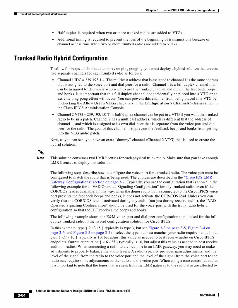
Chapter 3 Cisco IPICS LMR Gateway ConfigurationsTrunked Radio Optional Workaround
• Half duplex is required when two or more trunked radios are added to VTGs.
• Additional timing is required to prevent the loss of the beginning of transmissions because of channel access time when two or more trunked radios are added to VTGs.
Trunked Radio Hybrid ConfigurationTo allow for beeps and bonks and to prevent ping ponging, you must deploy a hybrid solution that creates two separate channels for each trunked radio as follows:
• Channel 1 IDC = 239.193.1.4. The multicast address that is assigned to channel 1 is the same address that is assigned to the voice port and dial peer for a radio. Channel 1 is a full duplex channel that can be assigned to IDC users who want to use the trunked channel and obtain the feedback beeps and bonks. It is important that this full duplex channel not accidentally be placed into a VTG or an extreme ping pong effect will occur. You can prevent this channel from being placed in a VTG by unchecking the Allow Use in VTGs check box in the Configuration > Channels > General tab in the Cisco IPICS Administration Console.
• Channel 2 VTG = 239.193.1.0 This half duplex channel can be put in a VTG if you want the trunked radio to be in a patch. Channel 2 has a multicast address, which is different that the address of channel 1, and which is assigned to its own dial-peer that is separate from the voice port and dial peer for the radio. The goal of this channel is to prevent the feedback beeps and bonks from getting into the VTG audio patch.
Now, as you can see, you have an extra “dummy” channel (Channel 2 VTG) that is used to create the hybrid solution.
Note This solution consumes two LMR licenses for each physical trunk radio. Make sure that you have enough LMR licenses to deploy this solution.
The following steps describe how to configure the voice port for a trunked radio. The voice port must be configured to match the radio that is being used. The choices are described in the “Cisco IOS LMR Gateway Configurations” section on page 3-7. Typically, you use the configuration that is shown in the following example for a “VAD Operated Signaling Configuration” for any trunked radio, even if the COR/COS lead is available. In this way, when the donor radio that is connected to the Cisco IPICS voice port presents the feedback beeps and bonks, it does not activate the COR/COS lead. Unless you can verify that the COR/COS lead is activated during any audio (not just during receive audio), the “VAD Operated Signaling Configuration” should be used for the voice-port with the trunk radio hybrid configuration so that the IDC receives the beeps and bonks.
The following example shows the E&M voice-port and dial peer configuration that is used for the full duplex trunked radio in the hybrid configuration solution for Cisco IPICS.
In this example, type { 2 | 3 | 5 } typically is type 3, but see Figure 3-3 on page 3-5, Figure 3-4 on page 3-6, and Figure 3-5 on page 3-7 to select the type that best matches your radio requirements. Input gain { -27 - 16 } typically is 10, but adjust this value as needed to best receive audio on Cisco IPICS endpoints. Output attenuation { -16 - 27 } typically is 10, but adjust this value as needed to best receive audio on radios. When connecting a radio to a voice port in an LMR gateway, you may need to make adjustments to properly balance the audio levels. A radio typically provides gain adjustments, and the level of the signal from the radio to the voice port and the level of the signal from the voice port to the radio may require some adjustments on the radio and the voice port. When using a tone controlled radio, it is important to note that the tones that are sent from the LMR gateway to the radio also are affected by
3-64Solution Reference Network Design (SRND) for Cisco IPICS Release 4.0(2)
OL-24067-01
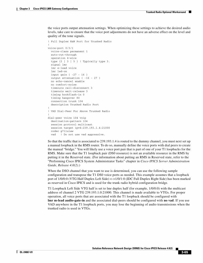
Chapter 3 Cisco IPICS LMR Gateway ConfigurationsTrunked Radio Optional Workaround
the voice ports output attenuation settings. When optimizing these settings to achieve the desired audio levels, take care to ensure that the voice port adjustments do not have an adverse effect on the level and quality of the tone signals.
! Full Duplex E&M Port for Trunked Radio!voice-port 0/3/1 voice-class permanent 1 auto-cut-through operation 4-wire type {2 | 3 | 5 } ! Typically type 3. signal lmr lmr e-lead voice lmr led-on input gain { -27 - 16 } output attenuation { -16 - 27 } no echo-cancel enable no comfort-noise timeouts call-disconnect 3 timeouts wait-release 3 timing hookflash-in 0 timing hangover 80 connection trunk 104 description Trunked Radio Port!! VAD Dial-Peer For Above Trunked Radio!dial-peer voice 104 voip destination-pattern 104 session protocol multicast session target ipv4:239.193.1.4:21000 codec g711ulaw vad ! Do not use vad aggressive.
So that the traffic that is associated to 239.193.1.4 is routed to the dummy channel, you must next set up a manual loopback in the RMS router. To do so, manually define the voice ports with dial peers to create the manual “bridge.” You will likely use a voice port pair that is part of one of your T1 loopbacks for the RMS. Make sure that the T1 loopback pair (DS0 resource) is not an available resource in the RMS by putting it in the Reserved state. (For information about putting an RMS in Reserved state, refer to the “Performing Cisco IPICS System Administrator Tasks” chapter in Cisco IPICS Server Administration Guide, Release 4.0(2).)
When the DSO channel that you want to use is determined, you can use the following sample configuration and transpose the T1 DS0 voice ports as needed. This example assumes that a loopback port of 1/0/0:0 (VTG Half Duplex Left Side) <->1/0/1:0 (IDC Full Duplex Right Side) has been marked as reserved in Cisco IPICS and is used for the trunk radio hybrid configuration bridge.
T1 Loopback Left Side VTG half is set to lmr duplex half (for example, 1/0/0:0) with the multicast address of channel 2 VTG 239.193.1.0:21000. This channel is made available to VTGs. For proper operation, all voice ports that are associated with the T1 loopback should be configured with lmr m-lead audio-gate-in and the associated dial-peers should be configured with no vad. If you use VAD anywhere in the T1 loopback ports, you may lose the beginning of audio transmissions when the trunked radio is used in VTGs.
3-65Solution Reference Network Design (SRND) for Cisco IPICS Release 4.0(2)
OL-24067-01
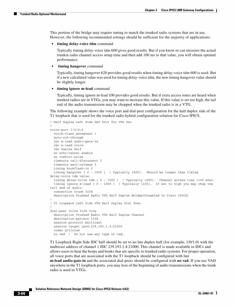
Chapter 3 Cisco IPICS LMR Gateway ConfigurationsTrunked Radio Optional Workaround
This portion of the bridge may require tuning to match the trunked radio systems that are in use. However, the following recommended settings should be sufficient for the majority of applications:
• timing delay-voice tdm command
Typically timing delay-voice tdm 600 gives good results. But if you know or can measure the actual trunkin radio channel access setup time and then add 100 ms to that value, you will obtain optimal performance.
• timing hangover command
Typically, timing hangover 620 provides good results when timing delay-voice tdm 600 is used. But if a new calculated value was used for timing delay-voice tdm, the new timing hangover value should be slightly longer.
• timing ignore m-lead command
Typically, timing ignore m-lead 100 provides good results. But if extra access tones are heard when trunked radios are in VTGs, you may want to increase this value. If this value is set too high, the tail end of the audio transmission may be chopped when the trunked radio is in a VTG.
The following example shows the voice port and dial-peer configuration for the half duplex side of the T1 loopback that is used for the trunked radio hybrid configuration solution for Cisco IPICS.
! Half Duplex Left Side DSO Port for VTG Use!voice-port 1/0/0:0 voice-class permanent 1 auto-cut-through lmr m-lead audio-gate-in lmr e-lead voice lmr duplex half no echo-cancel enable no comfort-noise timeouts call-disconnect 3 timeouts wait-release 3 timing hookflash-in 0 timing hangover { 0 - 1000 } ! Typically {620}. Should be longer than timing delay-voice tdm value. timing delay-voice tdm { 0 - 1500 } ! Typically {600}. Channel access time +100 mSec. timing ignore m-lead { 0 - 1000 } ! Typically {100}. If set to high you may chop the tail end of audio. connection trunk 3104 description Trunked Radio VTG Half Duplex Bridge(Disabled in Cisco IPICS)!! T1 Loopback Left Side VTG Half Duplex Dial Peer.!dial-peer voice 3104 voip description Trunked Radio VTG Half Duplex Channel destination-pattern 3104 session protocol multicast session target ipv4:239.193.1.0:21000 codec g711ulaw no vad ! Do not use any type of vad.
T1 Loopback Right Side IDC half should be set to no lmr duplex half (for example, 1/0/1:0) with the multicast address of channel 1 IDC 239.193.1.4:21000. This channel is made available to IDCs and allows users to hear the beeps and bonks that are specific to trunked radio systems. For proper operation, all voice ports that are associated with the T1 loopback should be configured with lmr m-lead audio-gate-in and the associated dial-peers should be configured with no vad. If you use VAD anywhere in the T1 loopback ports, you may lose of the beginning of audio transmissions when the trunk radio is used in VTGs.
3-66Solution Reference Network Design (SRND) for Cisco IPICS Release 4.0(2)
OL-24067-01
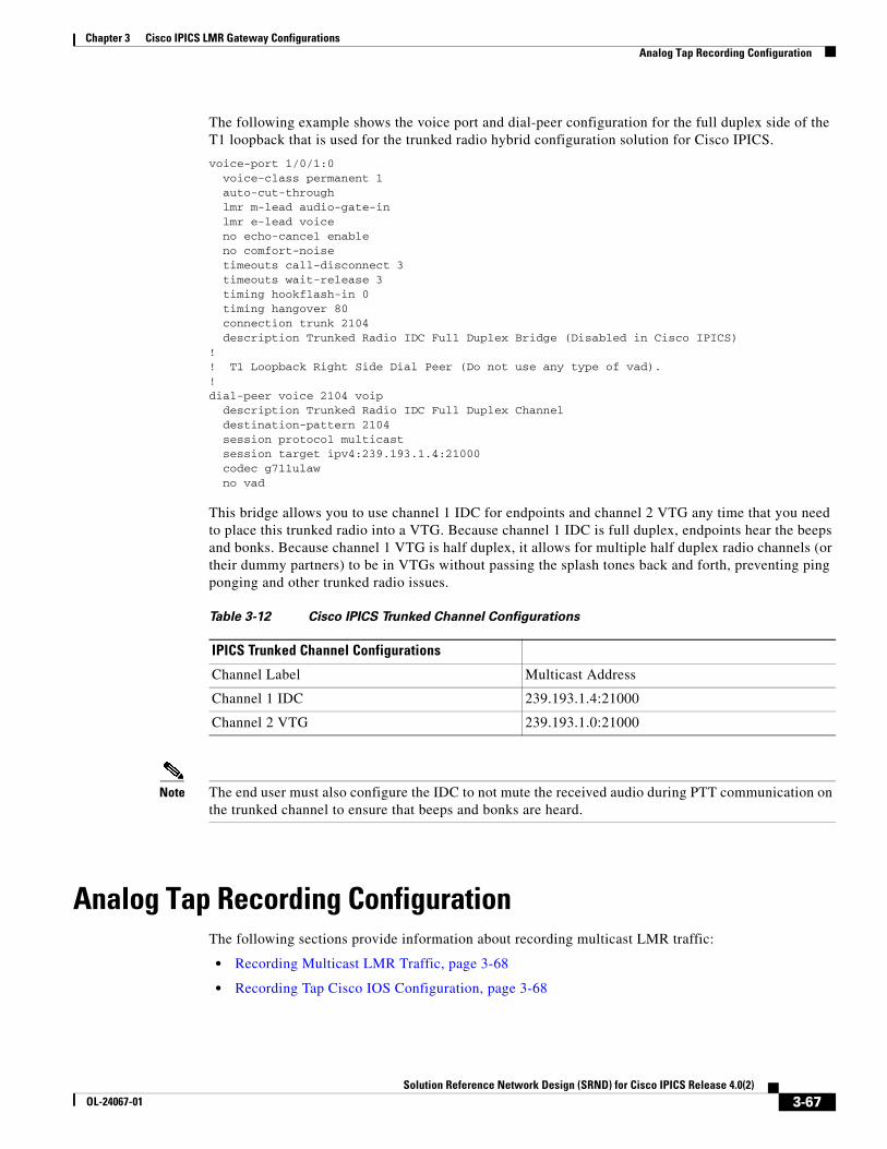
Chapter 3 Cisco IPICS LMR Gateway ConfigurationsAnalog Tap Recording Configuration
The following example shows the voice port and dial-peer configuration for the full duplex side of the T1 loopback that is used for the trunked radio hybrid configuration solution for Cisco IPICS.
voice-port 1/0/1:0 voice-class permanent 1 auto-cut-through lmr m-lead audio-gate-in lmr e-lead voice no echo-cancel enable no comfort-noise timeouts call-disconnect 3 timeouts wait-release 3 timing hookflash-in 0 timing hangover 80 connection trunk 2104 description Trunked Radio IDC Full Duplex Bridge (Disabled in Cisco IPICS)!! T1 Loopback Right Side Dial Peer (Do not use any type of vad).!dial-peer voice 2104 voip description Trunked Radio IDC Full Duplex Channel destination-pattern 2104 session protocol multicast session target ipv4:239.193.1.4:21000 codec g711ulaw no vad
This bridge allows you to use channel 1 IDC for endpoints and channel 2 VTG any time that you need to place this trunked radio into a VTG. Because channel 1 IDC is full duplex, endpoints hear the beeps and bonks. Because channel 1 VTG is half duplex, it allows for multiple half duplex radio channels (or their dummy partners) to be in VTGs without passing the splash tones back and forth, preventing ping ponging and other trunked radio issues.
Note The end user must also configure the IDC to not mute the received audio during PTT communication on the trunked channel to ensure that beeps and bonks are heard.
Analog Tap Recording ConfigurationThe following sections provide information about recording multicast LMR traffic:
• Recording Multicast LMR Traffic, page 3-68
• Recording Tap Cisco IOS Configuration, page 3-68
Table 3-12 Cisco IPICS Trunked Channel Configurations
IPICS Trunked Channel Configurations
Channel Label Multicast Address
Channel 1 IDC 239.193.1.4:21000
Channel 2 VTG 239.193.1.0:21000
3-67Solution Reference Network Design (SRND) for Cisco IPICS Release 4.0(2)
OL-24067-01
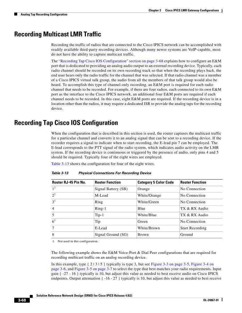
Chapter 3 Cisco IPICS LMR Gateway ConfigurationsAnalog Tap Recording Configuration
Recording Multicast LMR TrafficRecording the traffic of radios that are connected to the Cisco IPICS network can be accomplished with readily available third-party recording devices. Although many newer systems are VoIP-capable, most do not have the ability to capture multicast traffic.
The “Recording Tap Cisco IOS Configuration” section on page 3-68 explains how to configure an E&M port that is dedicated to providing an analog audio output to an external recording device. Typically, each radio channel should be recorded on its own recording track so that when the recording plays back, the end user hears only the radio traffic for the channel that was selected. If that radio channel was a member of a Cisco IPICS virtual talk group, the audio from all the members of that talk group would also be heard. To accomplish this type of channel-only recording, an E&M port is required for each radio channel that needs to be recorded. For example, if there are four radios, each connected to its own E&M port as the interface to the Cisco IPICS network, an additional four E&M ports are required if each channel needs to be recorded. In this case, eight E&M ports are required. If the recording device is in a location other than the radios, it may require a dedicated ISR to provide the analog taps for the recording device.
Recording Tap Cisco IOS ConfigurationWhen the configuration that is described in this section is used, the router captures the multicast traffic for a particular channel and converts it to an analog signal that can be sent to a recording device. If the recorder requires a signal to indicate when to start recording, the E-lead pin 7 can be employed. The E-lead corresponds to the PTT signal of the radio system, which indicates audio activity on the LMR system. If the recording device is continuous or triggered by the presence of audio, only pins 4 and 5 should be required. Typically four of the eight wires are employed.
Table 3-13 shows the configuration for four of the eight wires.
The following example shows the E&M Voice-Port & Dial Peer configurations that are required for recording multicast traffic on an analog recording device.
In this example, type { 2 | 3 | 5 } typically is type 3, but see Figure 3-3 on page 3-5, Figure 3-4 on page 3-6, and Figure 3-5 on page 3-7 to select the type that best matches your radio requirements. Input gain { -27 - 16 } typically is 10, but adjust this value as needed to best receive audio on Cisco IPICS endpoints. Output attenuation { -16 - 27 } typically is 10, but adjust this value as needed to best receive
Table 3-13 Physical Connections For Recording Device
Router RJ-45 Pin No. Router Function Category 5 Color Code Router Function
11
1. Not used in this configuration.
Signal Battery (SB) Orange No Connection
21 M-Lead White/Orange No Connection
31 Ring White/Green No Connection
4 Ring-1 Blue TX & RX Audio
5 Tip-1 White/Blue TX & RX Audio
61 Tip Green No Connection
7 E-Lead White/Brown Start Recording
8 Signal Ground (SG) Brown Ground
3-68Solution Reference Network Design (SRND) for Cisco IPICS Release 4.0(2)
OL-24067-01

Chapter 3 Cisco IPICS LMR Gateway ConfigurationsAnalog Tap Recording Configuration
audio on radios. When connecting a radio to a voice port in an LMR gateway, you may need to make adjustments to properly balance the audio levels. A radio typically provides gain adjustments, and the level of the signal from the radio to the voice port and the level of the signal from the voice port to the radio may require some adjustments on the radio and the voice port. When using a tone controlled radio, it is important to note that the tones that are sent from the LMR gateway to the radio also are affected by the voice ports output attenuation settings. When optimizing these settings to achieve the desired audio levels, take care to ensure that the voice port adjustments do not have an adverse effect on the level and quality of the tone signals.
ip multicast-routing!voice class codec 1 codec preference 1 g729r8 codec preference 2 g711ulaw!voice class permanent 1 signal timing oos timeout disabled signal keepalive disabled signal sequence oos no-action!voice-port 0/2/0 voice-class permanent 1 auto-cut-through operation 4-wire type { 2 | 3 | 5 } signal lmr lmr m-lead audio-gate-in lmr e-lead voice lmr duplex half lmr led-on output attenuation { -16 - 27 } no echo-cancel enable no comfort-noise timeouts call-disconnect 3 timeouts wait-release 3 timing hookflash-in 10 timing hangover 80 connection trunk 11101 description Recording Tap Radio 0/2/0 threshold noise -40!dial-peer voice 11101 voip destination-pattern 11101 session protocol multicast session target ipv4: { Multicast address of radio channel to be recorded } codec g711ulaw vad aggressive
3-69Solution Reference Network Design (SRND) for Cisco IPICS Release 4.0(2)
OL-24067-01

Chapter 3 Cisco IPICS LMR Gateway ConfigurationsAnalog Tap Recording Configuration
3-70Solution Reference Network Design (SRND) for Cisco IPICS Release 4.0(2)
OL-24067-01
Solution Reference NeOL-24067-01
C H A P T E R 4
Cisco IPICS Infrastructure ConsiderationsThis chapter contains information about infrastructure issues that you must be aware of when you deploy Cisco IPICS.
For related information, refer to the following documents:
• IP multicast—Refer to Cisco IOS IP Multicast Configuration Guide, Release 12.4:
http://www.cisco.com/en/US/products/ps6350/products_installation_and_configuration_guides_ list.html
• Quality of Service—Refer to Cisco IOS Quality of Service Solutions Configuration Guide, Release 12.4:
http://www.cisco.com/en/US/products/ps6350/products_installation_and_configuration_guides_ list.html
• Voice Configuration—Refer to Cisco IOS Voice Configuration Library:
http://www.cisco.com/en/US/products/ps6350/products_installation_and_configuration_guides_ list.html
• Hoot ‘n’ Holler—Refer to Hoot ‘n’ Holler Solution:
http://www.cisco.com/en/US/netsol/ns340/ns394/ns165/ns70/networking_solutions_ package.html
This chapter includes these topics:
• WAN Considerations, page 4-2
• Multicast Routing
• Bandwidth Planning
• Redundant RMS Configuration, page 4-9
• High Availability Considerations, page 4-32
• Quality of Service, page 4-34
• VPN in Deployment Scenarios, page 4-48
• Port Utilization, page 4-49
• Securing the Cisco IPICS Infrastructure, page 4-51
• Cisco IPICS Network Management System, page 4-52
4-1twork Design (SRND) for Cisco IPICS Release 4.0(2)
Chapter 4 Cisco IPICS Infrastructure ConsiderationsWAN Considerations
WAN ConsiderationsTo ensure the successful deployment of Cisco IPICS over a WAN, you must carefully plan, design, and implement the WAN. Make sure to consider the following factors:
• Delay—Propagation delay between two sites introduces 6 microseconds per kilometer. Other network delays may also be present.
• Quality of Service—The network infrastructure relies on QoS engineering to provide consistent and predictable end-to-end levels of service for traffic. QoS-enabled bandwidth must be engineered into the network infrastructure.
• Jitter—Varying delay that packets incur through the network as a result of processing, queue, buffer, congestion, or path variation delay. Jitter for the multicast voice traffic must be minimized by using Quality of Service (QoS) features. For related information, see the “Quality of Service” section on page 4-34.
• Packet loss and errors—The network should be engineered to provide sufficient prioritized bandwidth for all voice traffic. Standard QoS mechanisms must be implemented to avoid congestion and packet loss. For related information, see the “Quality of Service” section on page 4-34.
• Bandwidth—Provision the correct amount of bandwidth between each site for the expected call volume. This bandwidth is in addition to bandwidth for other applications and traffic that share the network. The provisioned bandwidth must have QoS enabled to provide prioritization and scheduling for the different classes of traffic. In general, the bandwidth should be over-provisioned and under-subscribed.
• IDCs using remote location—IDCs that choose the remote location use SIP to set up the connection to the RMS. Because SIP is sensitive to latency and excessive delays, this type of connection may experience timeouts and call setup failures. If you experience connectivity or audio quality issues when you use an IDC that is deployed over a WAN, Cisco recommends that you try to isolate the problem by testing a remote IDC connection that is not deployed over a WAN. If you cannot duplicate the problem on the IDC that is not deployed over the WAN, Cisco recommends that you assess the WAN infrastructure to determine if excessive latency or resource limitations in the WAN are causing the problems.
• The IDC communicates on all associated multicast channels even when the channels are powered off in the IDC. To conserve system resources on the RMS component, Cisco recommends that the following ACL be implemented on the incoming interface of the RMS component. This ACL must match the multicast groups and port numbers that are used for Cisco IPICS. For example:
ip access-list extended RTCP-MCAST deny UDP any 239.220.0.0 0.0.255.255 eq 21001 permit any any
• The VIF and loopback interfaces of the RMS component must be advertised to avoid one-way audio.
Multicast RoutingCisco supports the Protocol Independent Multicast (PIM) routing protocol for both sparse mode (SM) and dense mode (DM). However, because of its periodic broadcast and prune mechanism, DM PIM is not recommended for production networks.
Cisco recommends using bidirectional PIM for Cisco IPICS. Bidirectional PIM is an extension of the PIM suite of protocols that implements shared sparse trees with bidirectional data flow. In contrast to PIM-sparse mode, bidirectional PIM avoids keeping source-specific states in a router and allows trees to scale to an arbitrary number of sources while requiring only minimal additional overhead.
4-2Solution Reference Network Design (SRND) for Cisco IPICS Release 4.0(2)
OL-24067-01
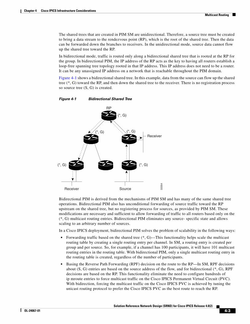
Chapter 4 Cisco IPICS Infrastructure ConsiderationsMulticast Routing
The shared trees that are created in PIM SM are unidirectional. Therefore, a source tree must be created to bring a data stream to the rendezvous point (RP), which is the root of the shared tree. Then the data can be forwarded down the branches to receivers. In the unidirectional mode, source data cannot flow up the shared tree toward the RP.
In bidirectional mode, traffic is routed only along a bidirectional shared tree that is rooted at the RP for the group. In bidirectional PIM, the IP address of the RP acts as the key to having all routers establish a loop-free spanning tree topology rooted in that IP address. This IP address does not need to be a router. It can be any unassigned IP address on a network that is reachable throughout the PIM domain.
Figure 4-1 shows a bidirectional shared tree. In this example, data from the source can flow up the shared tree (*, G) toward the RP, and then down the shared tree to the receiver. There is no registration process so source tree (S, G) is created.
Figure 4-1 Bidirectional Shared Tree
Bidirectional PIM is derived from the mechanisms of PIM SM and has many of the same shared tree operations. Bidirectional PIM also has unconditional forwarding of source traffic toward the RP upstream on the shared tree, but no registering process for sources, as provided by PIM SM. These modifications are necessary and sufficient to allow forwarding of traffic to all routers based only on the (*, G) multicast routing entries. Bidirectional PIM eliminates any source- specific state and allows scaling to an arbitrary number of sources.
In a Cisco IPICS deployment, bidirectional PIM solves the problem of scalability in the following ways:
• Forwarding traffic based on the shared tree (*, G)—This functionality helps scale the multicast routing table by creating a single routing entry per channel. In SM, a routing entry is created per group and per source. So, for example, if a channel has 100 participants, it will have 101 multicast routing entries in the routing table. With bidirectional PIM, only a single multicast routing entry in the routing table is created, regardless of the number of participants.
• Basing the Reverse Path Forwarding (RPF) decision on the route to the RP—In SM, RPF decisions about (S, G) entries are based on the source address of the flow, and for bidirectional (*, G), RPF decisions are based on the RP. This functionality eliminate the need to configure hundreds of ip mroute entries to force multicast traffic on the Cisco IPICS Permanent Virtual Circuit (PVC). With bidirection, forcing the multicast traffic on the Cisco IPICS PVC is achieved by tuning the unicast routing protocol to prefer the Cisco IPICS PVC as the best route to reach the RP.
Receiver Source
RP
(*, G) (*, G)
(*, G)(*, G)
Receiver
3335
4
(*, G)
4-3Solution Reference Network Design (SRND) for Cisco IPICS Release 4.0(2)
OL-24067-01
Chapter 4 Cisco IPICS Infrastructure ConsiderationsBandwidth Planning
If you are using Auto-RP and a Cisco IOS release earlier than 12.2(7), sparse dense mode is required. If you are using Auto-RP and Cisco IOS release 12.2(7) or later, use the sparse mode and ip pim auto rp listener commands. Multicast types other than auto-rp can use sparse mode.
Note Cisco recommends that static RPs be used in a large deployments. This approach helps with control of the multicast tree and provides a stable and a deterministic path for Cisco IPICS traffic.
Bandwidth PlanningTo ensure sufficient bandwidth for the operation of Cisco IPICS, consider the following issues as you plan and deploy your network. These issues include:
• Codec used for VoIP—See the “Codecs” section on page 4-4
• The number of voice streams that will be mixed—See the “Mixing Voice Streams” section on page 4-8
In addition, you should consider the guaranteed bandwidth that is available on the VoIP network. Make sure to take into account both LAN and WAN bandwidth, and to consider factors such as Frame Relay, Committed Information Rate (CIR) or Asynchronous Transfer Mode Peak Cell Rate (ATM PCR), Sustained Cell Rate, and burst. For additional information see the “Quality of Service” section on page 4-34.
CodecsCisco IPICS uses either the G.711 or G.729a codec. This section provides the following information about codecs:
• Choosing a Codec, page 4-4
• Calculating Codec Bandwidth Use, page 4-5
Note The Cisco IPICS policy engine supports only G.711 u-law. If you use the policy engine, you must use this codec.
Choosing a Codec
When choosing a codec for Cisco IPICS, consider the issues that are described in Table 4-1.
4-4Solution Reference Network Design (SRND) for Cisco IPICS Release 4.0(2)
OL-24067-01
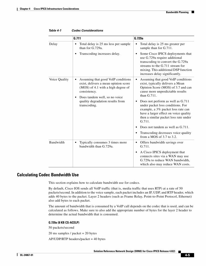
Chapter 4 Cisco IPICS Infrastructure ConsiderationsBandwidth Planning
Calculating Codec Bandwidth Use
This section explains how to calculate bandwidth use for codecs.
By default, Cisco IOS sends all VoIP traffic (that is, media traffic that uses RTP) at a rate of 50 packets/second. In addition to the voice sample, each packet includes an IP, UDP, and RTP header, which adds 40 bytes to the packet. Layer 2 headers (such as Frame Relay, Point-to-Point Protocol, Ethernet) also add bytes to each packet.
The amount of bandwidth that is consumed by a VoIP call depends on the codec that is used, and can be calculated as follows. Make sure to also add the appropriate number of bytes for the layer 2 header to determine the actual bandwidth that is consumed.
G.729a (8 KB CS-ACELP)
50 packets/second
20 ms samples / packet = 20 bytes
AP/UDP/RTP headers/packet = 40 bytes
Table 4-1 Codec Considerations
G.711 G.729a
Delay • Total delay is 25 ms less per sample than for G.729a.
• Transcoding increases delay.
• Total delay is 25 ms greater per sample than for G.711.
• Some Cisco IPICS deployments that use G.729a require additional transcoding to convert the G.729a streams to the G.711 stream for mixing. This additional DSP function increases delay significantly.
Voice Quality • Assuming that good VoIP conditions exist, delivers a mean opinion score (MOS) of 4.1 with a high degree of consistency.
• Does tandem well, so no voice quality degradation results from transcoding.
• Assuming that good VoIP conditions exist, typically delivers a Mean Opinion Score (MOS) of 3.7 and can cause more unpredictable results than G.711.
• Does not perform as well as G.711 under packet loss conditions. For example, a 3% packet loss rate can have a larger effect on voice quality then a similar packet loss rate under G.711.
• Does not tandem as well as G.711.
• Transcoding decreases voice quality from a MOS of 3.7 to 3.2.
Bandwidth • Typically consumes 3 times more bandwidth than G.729a.
• Offers bandwidth savings over G.711.
• A Cisco IPICS deployment that connects sites via a WAN may use G.729a to reduce WAN bandwidth, which also may reduce WAN costs.
4-5Solution Reference Network Design (SRND) for Cisco IPICS Release 4.0(2)
OL-24067-01
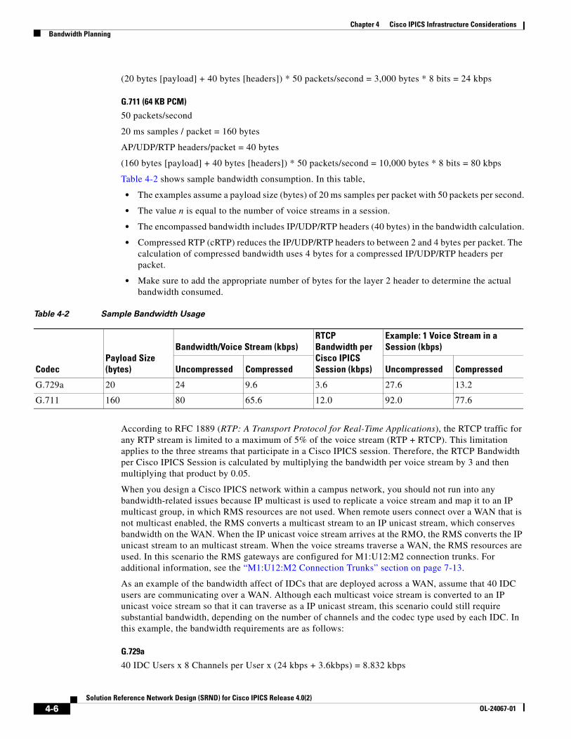
Chapter 4 Cisco IPICS Infrastructure ConsiderationsBandwidth Planning
(20 bytes [payload] + 40 bytes [headers]) * 50 packets/second = 3,000 bytes * 8 bits = 24 kbps
G.711 (64 KB PCM)
50 packets/second
20 ms samples / packet = 160 bytes
AP/UDP/RTP headers/packet = 40 bytes
(160 bytes [payload] + 40 bytes [headers]) * 50 packets/second = 10,000 bytes * 8 bits = 80 kbps
Table 4-2 shows sample bandwidth consumption. In this table,
• The examples assume a payload size (bytes) of 20 ms samples per packet with 50 packets per second.
• The value n is equal to the number of voice streams in a session.
• The encompassed bandwidth includes IP/UDP/RTP headers (40 bytes) in the bandwidth calculation.
• Compressed RTP (cRTP) reduces the IP/UDP/RTP headers to between 2 and 4 bytes per packet. The calculation of compressed bandwidth uses 4 bytes for a compressed IP/UDP/RTP headers per packet.
• Make sure to add the appropriate number of bytes for the layer 2 header to determine the actual bandwidth consumed.
According to RFC 1889 (RTP: A Transport Protocol for Real-Time Applications), the RTCP traffic for any RTP stream is limited to a maximum of 5% of the voice stream (RTP + RTCP). This limitation applies to the three streams that participate in a Cisco IPICS session. Therefore, the RTCP Bandwidth per Cisco IPICS Session is calculated by multiplying the bandwidth per voice stream by 3 and then multiplying that product by 0.05.
When you design a Cisco IPICS network within a campus network, you should not run into any bandwidth-related issues because IP multicast is used to replicate a voice stream and map it to an IP multicast group, in which RMS resources are not used. When remote users connect over a WAN that is not multicast enabled, the RMS converts a multicast stream to an IP unicast stream, which conserves bandwidth on the WAN. When the IP unicast voice stream arrives at the RMO, the RMS converts the IP unicast stream to an multicast stream. When the voice streams traverse a WAN, the RMS resources are used. In this scenario the RMS gateways are configured for M1:U12:M2 connection trunks. For additional information, see the “M1:U12:M2 Connection Trunks” section on page 7-13.
As an example of the bandwidth affect of IDCs that are deployed across a WAN, assume that 40 IDC users are communicating over a WAN. Although each multicast voice stream is converted to an IP unicast voice stream so that it can traverse as a IP unicast stream, this scenario could still require substantial bandwidth, depending on the number of channels and the codec type used by each IDC. In this example, the bandwidth requirements are as follows:
G.729a
40 IDC Users x 8 Channels per User x (24 kbps + 3.6kbps) = 8.832 kbps
Table 4-2 Sample Bandwidth Usage
CodecPayload Size (bytes)
Bandwidth/Voice Stream (kbps)RTCP Bandwidth per Cisco IPICS Session (kbps)
Example: 1 Voice Stream in a Session (kbps)
Uncompressed Compressed Uncompressed Compressed
G.729a 20 24 9.6 3.6 27.6 13.2
G.711 160 80 65.6 12.0 92.0 77.6
4-6Solution Reference Network Design (SRND) for Cisco IPICS Release 4.0(2)
OL-24067-01
Chapter 4 Cisco IPICS Infrastructure ConsiderationsBandwidth Planning
G.711
40 IDC Users x 8 Channels per User x (80 kbps + 12 kbps) = 29,440 kbps
Note Each Cisco IPICS dial engine port uses the G.711 codec. Bandwidth calculations must consider the G.711 connectivity between the Cisco IPICS server and connected endpoints.
cRTP, Variable-Payload Sizes and Aggressive VADThere are several methods that you can use to modify the bandwidth consumed by a call. These methods include the following:
• RTP Header Compression, page 4-7
• Adjustable Byte Size of the Voice Payload, page 4-7
• Aggressive Voice Activity Detection, page 4-8
RTP Header Compression
As described in the “Codecs” section on page 4-4, IP/UDP/RTP headers add 40 bytes to each packet. However, a packet header is typically unchanged throughout a call. You can enable cRTP for VoIP calls, which reduces the size of IP/UDP/RTP headers to 2 to 4 bytes per packet.
For detailed information about cRTP, refer to Understanding Compression (Including cRTP) and Quality of Service, which is available at this URL:
http://www.cisco.com/en/US/tech/tk543/tk762/technologies_tech_note09186a0080108e2c. shtml
Adjustable Byte Size of the Voice Payload
You can control the size of the voice payload that is included in each Cisco IPICS voice packet. To do so, use the bytes parameter in a VoIP dial peer. For example:
dial-peer voice 1 voipdestination-pattern 4085551234codec g729r8 bytes 40session protocol multicastsession target ipv4:239.192.1.1:21000
Modifying the number of bytes per packet changes the number of packets that are sent per second. You can calculate the number of packets that are sent per second as shown in these examples:
G.729a codec, with default 20byte payload/packet
Codec rate: 8,000 bits/second * 8 bits = 1,000 byes/second
Sampling interval: 10 ms
Default payload size: 20 bytes/packet (2 samples/packet)
1,000 bytes/sec/20bytes/pkt = 50 packets/sec
G.729a codec, with 40 bytes defined in VoIP dial-peer
Codec rate: 8,000 bits/second * 8 bits = 1,000 byes/second
4-7Solution Reference Network Design (SRND) for Cisco IPICS Release 4.0(2)
OL-24067-01
Chapter 4 Cisco IPICS Infrastructure ConsiderationsBandwidth Planning
Sampling interval: 10 ms
Payload size: 40 bytes/packet
1,000 bytes/sec/40 bytes/pkt = 25 packets/sec
Note Increasing payload size increases the delay per sample by the same amount. For example, increasing payload size from 20 ms to 40 ms increases the delay per sample by 20 ms.
Aggressive Voice Activity Detection
Voice Activation Detection (VAD) is a mechanism that allows a DSP to dynamically sense pauses in conversation. When such pauses occur, no VoIP packets are sent into the network. VAD can reduce the amount of bandwidth used for a VoIP call by up to 50%.
Although VAD conserves bandwidth in VoIP, it disrupts and marginalizes Cisco IPICS signaling, which is used for LMR and PTT packet streams. Be aware of this issue if you use VAD in a Cisco IPICS deployment.
When configuring LMR gateway ports, VAD should not be used if the radio supports Carrier Operated Relay (COR) or Carrier Operated Squelch (COS). Radios that support COR/COS signaling can provide hardwired signaling to the LMR port to start generating packets. Using COR/COS gating is an efficient way to control the audio input and to avoid the possibility of dropping short burst of voice data that may fall below the VAD activation values.
Each voice port has different environmental noises and different users, which can cause a wide variation in noise and speech levels. Conventional VAD can manage these variations, but it is designed for unicast. Conventional VAD usually prefers over-detection to under-detection, as good voice quality is typically given precedence over bandwidth conservation. But in a multicast environment, over-detection and under-detection are not desirable because they degrade voice quality.
Aggressive VAD can be used in a multicast environment to avoid over-detection. With aggressive VAD, when a DSP detects signals with an unknown signal-to-noise ratio (SNR), the DSP does not transmit any spurious packets. With conventional VAD, when the DSP detects signals with an unknown SNR, the DSP continues to transmit packets, which can cause unwanted traffic to take over all slots that are available for voice streams.
You can enable aggressive VAD by enabling the vad aggressive configuration setting under a dial peer as follows:
dial-peer voice 10 voipdestination-pattern 111session protocol multicastsession target ipv4:239.192.1.1:21000vad aggressive
Mixing Voice StreamsAs described in the “Virtual Talk Groups” section on page 2-11, the DSPs in a Cisco IPICS deployment can mix up to three voice streams. However, the DSPs do not perform a summation function. So, for example, if three G.729a streams (24 KB each with headers) are received by a router or gateway, the mixed stream would consume 72 KB bandwidth. Even though each user in a VTG or a channel in the VTG receives a single mixed audio stream, the DSP does not send a single 24 KB stream.
4-8Solution Reference Network Design (SRND) for Cisco IPICS Release 4.0(2)
OL-24067-01
Chapter 4 Cisco IPICS Infrastructure ConsiderationsRedundant RMS Configuration
It is important to consider this issue when you plan bandwidth in a Cisco IPICS network. It is especially important when planning WAN bandwidth, which can be more expensive and less available then LAN bandwidth.
Because the Cisco Hoot ‘n’ Holler feature mixes up to three voice streams at a time, you do not need to provision voice bandwidth for more than three times the per-call bandwidth for each WAN site that includes routers with the Cisco Hoot ‘n’ Holler feature.
Note An audio channel that is mixed through a VTG experiences an additional 60 ms of delay.
Redundant RMS ConfigurationThis section presents a case study that demonstrates how to configure a network to support redundant RMS components in a Cisco IPICS deployment. This tested solution uses primary and backup multicast Generic Routing Encapsulation (GRE) tunnels. It assigns the same IP address to a loopback interface in each RMS, which allows the Cisco IPICS server to access the active RMS (called RMS1 in this example) or the backup RMS (RMS2) with no special considerations in the server code. This approach is possible because the GRE tunnels are configured so that only one RMS can be active at any time. Failover occurs when all connectivity to the primary RMS is lost. When the primary tunnel goes down, the backup tunnel becomes active, allowing access to the backup RMS. Connectivity is restored when the backup tunnel becomes active and the Cisco IPICS server synchronizes the RMS configuration. The default synchronization process runs every 10 minutes, so the failover can take up to approximately 10 minutes to complete.
With this topology, there are two paths to the active RMS. Therefore, both paths must fail at the same time before the standby RMS needs to become active. If the active RMS itself fails, the backup tunnels become active.
In this configuration, the RMS routers must have identical hardware (same hardware modules in the same slots).
This section includes these topics:
• Topology, page 4-9
• Cabling, page 4-11
• Routing Overview, page 4-12
• Failure Scenario Behavior, page 4-13
• Caveats, page 4-14
• Router Configurations, page 4-14
TopologyThe redundant RMS configuration requires four routers for each RMS that is in a deployment. With this topology, there are no single points of failure. The topology that is described in this example uses a core of three routers. One router, called GW3, that provides connectivity to the devices. The other routers, called GW1 and GW2, provide fully redundant routing between the core and the redundant RMS devices.
4-9Solution Reference Network Design (SRND) for Cisco IPICS Release 4.0(2)
OL-24067-01
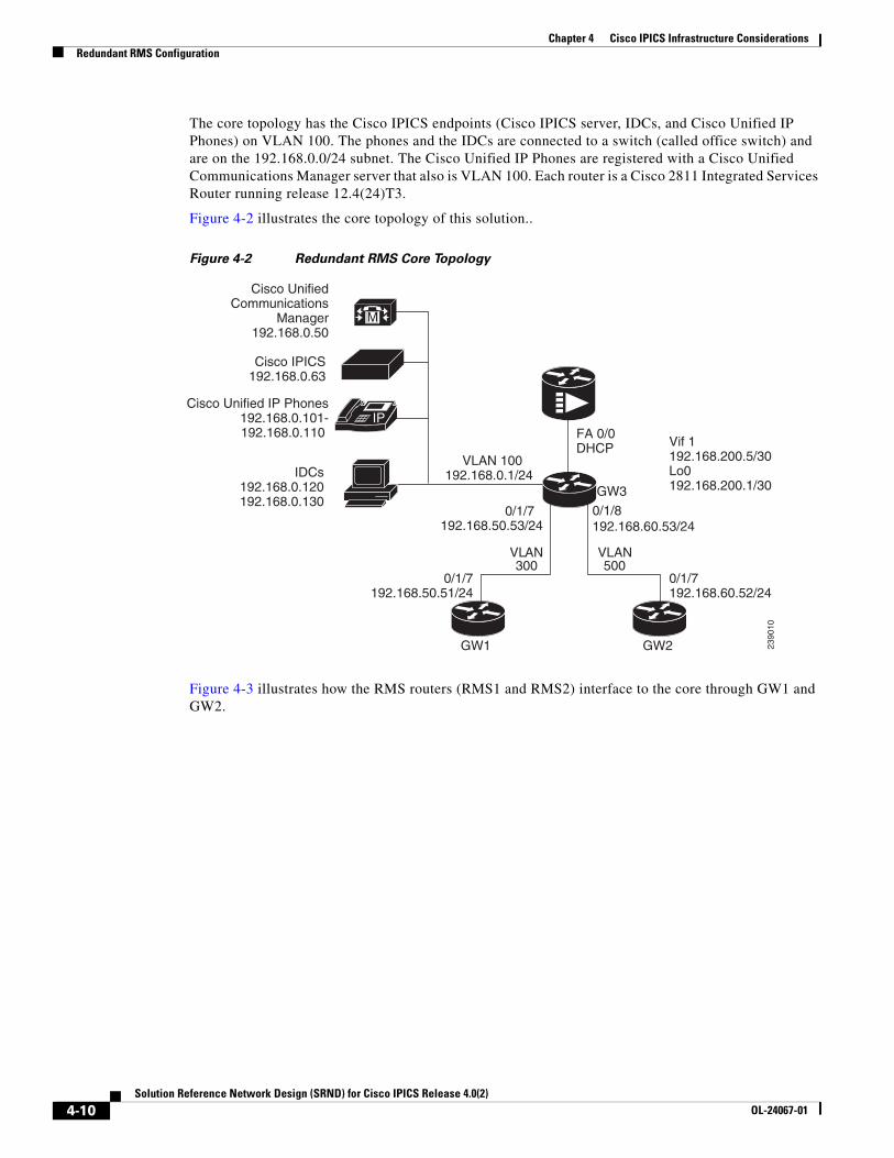
Chapter 4 Cisco IPICS Infrastructure ConsiderationsRedundant RMS Configuration
The core topology has the Cisco IPICS endpoints (Cisco IPICS server, IDCs, and Cisco Unified IP Phones) on VLAN 100. The phones and the IDCs are connected to a switch (called office switch) and are on the 192.168.0.0/24 subnet. The Cisco Unified IP Phones are registered with a Cisco Unified Communications Manager server that also is VLAN 100. Each router is a Cisco 2811 Integrated Services Router running release 12.4(24)T3.
Figure 4-2 illustrates the core topology of this solution..
Figure 4-2 Redundant RMS Core Topology
Figure 4-3 illustrates how the RMS routers (RMS1 and RMS2) interface to the core through GW1 and GW2.
FA 0/0 DHCP
VLAN 100 192.168.0.1/24
0/1/7192.168.50.53/24
VLAN 300
VLAN 500
Cisco Unified IP Phones 192.168.0.101-
192.168.0.110
Cisco IPICS 192.168.0.63
Cisco UnifiedCommunications
Manager 192.168.0.50
M
IP
IDCs192.168.0.120192.168.0.130
GW3
GW1 GW2
0/1/7192.168.50.51/24
0/1/7192.168.60.52/24
2390
10
Vif 1192.168.200.5/30Lo0192.168.200.1/30
0/1/8192.168.60.53/24
4-10Solution Reference Network Design (SRND) for Cisco IPICS Release 4.0(2)
OL-24067-01
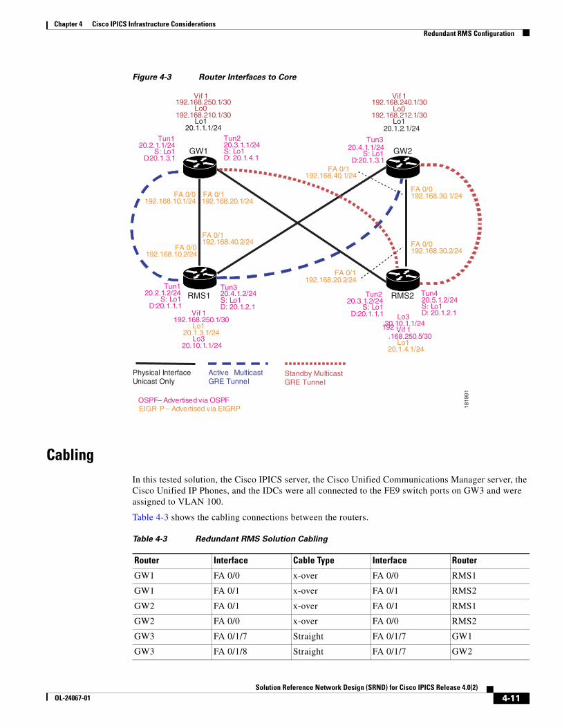
Chapter 4 Cisco IPICS Infrastructure ConsiderationsRedundant RMS Configuration
Figure 4-3 Router Interfaces to Core
CablingIn this tested solution, the Cisco IPICS server, the Cisco Unified Communications Manager server, the Cisco Unified IP Phones, and the IDCs were all connected to the FE9 switch ports on GW3 and were assigned to VLAN 100.
Table 4-3 shows the cabling connections between the routers.
Physical Interface Unicast Only
Active Multicast GRE Tunnel
Standby MulticastGRE Tunnel
Tun1 20.2.1.2/24
S: Lo1 D:20.1.1.1
Tun3 20.4.1.2/24 S: Lo1 D: 20.1.2.1
FA 0/0 192.168.10.2/24
FA 0/1 192.168.40.2/24
Vif 1 192.168.250.1/30
Lo1 20.1.3.1/24
Lo3 20.10.1.1/24
Tun1 20.2.1.1/24
S: Lo1 D:20.1.3.1
Tun2 20.3.1.1/24 S: Lo1 D: 20.1.4.1
FA 0/0 192.168.10.1/24
FA 0/1 192.168.20.1/24
Vif 1 192.168.250.1/30
Lo0 192.168.210.1/30
Lo1 20.1.1.1/24
Tun2 20.3.1.2/24
S: Lo1 D:20.1.1.1
Tun4 20.5.1.2/24 S: Lo1 D: 20.1.2.1
Lo3 20.10.1.1/24
Vif 1 192.168.250.5/30
Lo1 20.1.4.1/24
FA 0/1
192.168.20.2/24
FA 0/0 192.168.30.2/24
Tun3 20.4.1.1/24
S: Lo1 D:20.1.3.1
FA 0/0 192.168.30.1/24
FA 0/1
192.168.40.1/24
Vif 1 192.168.240.1/30
Lo0 192.168.212.1/30
Lo1 20.1.2.1/24
OSPF – Advertised via OSPF EIGR P – Advertised via EIGRP
GW1
RMS1 RMS2
GW2
1819
91
Table 4-3 Redundant RMS Solution Cabling
Router Interface Cable Type Interface Router
GW1 FA 0/0 x-over FA 0/0 RMS1
GW1 FA 0/1 x-over FA 0/1 RMS2
GW2 FA 0/1 x-over FA 0/1 RMS1
GW2 FA 0/0 x-over FA 0/0 RMS2
GW3 FA 0/1/7 Straight FA 0/1/7 GW1
GW3 FA 0/1/8 Straight FA 0/1/7 GW2
4-11Solution Reference Network Design (SRND) for Cisco IPICS Release 4.0(2)
OL-24067-01
Chapter 4 Cisco IPICS Infrastructure ConsiderationsRedundant RMS Configuration
Routing OverviewAs shown in Figure 4-2 on page 4-10, Enhanced Interior Gateway Routing Protocol (EIGRP) and Open Shortest Path First (OSPF) are implemented in the tested solution to dynamically advertise the routes and to facilitate the desired connectivity. However, any dynamic routing protocols can be used between the GW1 and GW2 routers and the RMS routers.
If you choose to deploy the redundant RMS solution by using different routing protocols than those that were tested, follow these general steps:
1. Configure a routing protocol on the physical interfaces between GW1, GW2, RMS1, and RMS 2 and advertise the loopback 0 interfaces. The loopback 0 interfaces on GW1, GW2, RMS1, and RMS 2 are used as the tunnel endpoints. After the loopback interfaces are advertised between the routers, the multicast GRE tunnels can be configured. The physical interfaces between GW1 and GW2 and the RMS routers are unicast-only interfaces.
2. Configure primary and backup multicast GRE tunnels between GW1, GW2, RMS1, and RMS2. Tunnel endpoints are the lo0 interfaces. Configure a second routing protocol on the tunnels and advertise all other networks. All multicast traffic between the GW1, GW2, RMS1, and RMS2 will be over the tunnels. All multicast traffic from the RMS routers has a source address of the virtual interface (VIF). Because the VIF subnet is advertised over the tunnels, the RPF check on the gateway routers will always succeed. All multicast traffic to the RMS will be over the tunnel and again the RPF check will succeed without the need for static multicast routes.
3. Configure another loopback interface with the same IP address on RMS1 and on RMS2. This address is the one that is configured on the Cisco IPICS server for the RMS. Add this address to the routing protocol that is configured on the tunnels. Because this common IP address is advertised over the tunnels, the network will receive only one advertisement for the address via the active tunnels.
Normal Operation
Under normal operation, the tunnels to RMS2 are in standby mode so that the common loopback address is not advertised to the gateway routers and there is no multicast path from RMS2 to the rest of the network. The Cisco IPICS server controls the active RMS. From a routing standpoint, the common loopback address on RMS2 does not exist.
Failure Mode
Loss of connectivity to RMS1 typically happens only if RMS1 fails. No single point of failure will cause loss of network connectivity to RMS1. If RMS1 fails, the active tunnels time out due to the keepalive configuration. When the tunnels time out, the secondary tunnels become active, the common loopback address is advertised by RMS2, and tunnels are established, for multicast traffic, from RMS2 to GW1 and GW2. When the Cisco IPICS server performs the periodic check of the RMS (which occurs every 10 minutes by default), the configuration on RMS2 is updated to match the configuration on RMS1.
Fail Back Mode
If RMS1 comes back on line, it becomes the active RMS and the tunnels to RMS2 return to standby mode.
4-12Solution Reference Network Design (SRND) for Cisco IPICS Release 4.0(2)
OL-24067-01
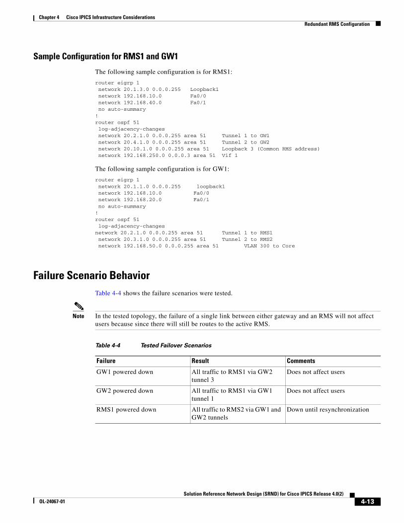
Chapter 4 Cisco IPICS Infrastructure ConsiderationsRedundant RMS Configuration
Sample Configuration for RMS1 and GW1
The following sample configuration is for RMS1:
router eigrp 1 network 20.1.3.0 0.0.0.255 Loopback1 network 192.168.10.0 Fa0/0 network 192.168.40.0 Fa0/1 no auto-summary!router ospf 51 log-adjacency-changes network 20.2.1.0 0.0.0.255 area 51 Tunnel 1 to GW1 network 20.4.1.0 0.0.0.255 area 51 Tunnel 2 to GW2 network 20.10.1.0 0.0.0.255 area 51 Loopback 3 (Common RMS address) network 192.168.250.0 0.0.0.3 area 51 Vif 1
The following sample configuration is for GW1:
router eigrp 1 network 20.1.1.0 0.0.0.255 loopback1 network 192.168.10.0 Fa0/0 network 192.168.20.0 Fa0/1 no auto-summary!router ospf 51 log-adjacency-changesnetwork 20.2.1.0 0.0.0.255 area 51 Tunnel 1 to RMS1 network 20.3.1.0 0.0.0.255 area 51 Tunnel 2 to RMS2 network 192.168.50.0 0.0.0.255 area 51 VLAN 300 to Core
Failure Scenario BehaviorTable 4-4 shows the failure scenarios were tested.
Note In the tested topology, the failure of a single link between either gateway and an RMS will not affect users because since there will still be routes to the active RMS.
Table 4-4 Tested Failover Scenarios
Failure Result Comments
GW1 powered down All traffic to RMS1 via GW2 tunnel 3
Does not affect users
GW2 powered down All traffic to RMS1 via GW1 tunnel 1
Does not affect users
RMS1 powered down All traffic to RMS2 via GW1 and GW2 tunnels
Down until resynchronization
4-13Solution Reference Network Design (SRND) for Cisco IPICS Release 4.0(2)
OL-24067-01
Chapter 4 Cisco IPICS Infrastructure ConsiderationsRedundant RMS Configuration
CaveatsBe aware of the following caveats when you implement a redundant RMS solution:
• The Cisco IPICS server runs a polling routine every 10 minutes. This routine synchronizes the RMS to the server configuration. If RMS1 fails, there may be up to a 10 minute delay before the synchronization routine runs on RMS2. The time that RMS2 takes to synchronize depends on network latency and on the number of RMS resources that are currently configured.
From the Cisco IPICS Administration Console, you can change the polling period by entering a new value in the RMS Polling Frequency field in the Options window in the Administration drawer. You can also execute the synchronization manually from this drawer. For more information about these procedures, refer to the “Performing Cisco IPICS System Administrator Tasks” chapter in Cisco IPICS Server Administration Guide, Release 4.0(2).
• When connectivity to the active RMS is restored after a failover, the system falls back.
Router ConfigurationsThe following sections show the output from the show running-config command from the routers in the tested solution. The RMS voice-port and dial-peer configuration that was performed by the Cisco IPICS server has been removed to conserve space.
• GW1 Configuration, page 4-14
• GW2 Configuration, page 4-17
• GW3 Configuration, page 4-19
• RMS1 Configuration, page 4-24
• RMS2 Configuration, page 4-28
GW1 Configuration
The following configuration is for GW1:
version 12.4no service padservice tcp-keepalives-inservice tcp-keepalives-outservice timestamps debug datetime msec localtime show-timezoneservice timestamps log datetime msec localtime show-timezoneservice password-encryptionservice sequence-numbers!hostname gw1!boot-start-markerboot system flash 1244t.binboot-end-marker!! card type command needed for slot 1! card type command needed for slot 1security passwords min-length 6logging buffered 51200 warningsenable password 7 0822455D0A16544541!aaa new-model!
4-14Solution Reference Network Design (SRND) for Cisco IPICS Release 4.0(2)
OL-24067-01

Chapter 4 Cisco IPICS Infrastructure ConsiderationsRedundant RMS Configuration
aaa authentication login default local!aaa session-id common!resource policy!no network-clock-participate slot 1 ip subnet-zerono ip source-routeip tcp synwait-time 10!ip cefno ip dhcp use vrf connectedip dhcp excluded-address 192.168.0.1ip dhcp excluded-address 192.168.0.1 192.168.0.9ip dhcp excluded-address 192.168.0.20 192.168.0.255ip dhcp excluded-address 192.168.100.1!ip dhcp pool sub-100 network 192.168.100.0 255.255.255.0 default-router 192.168.0.1 option 150 ip 192.168.0.50 dns-server 68.87.71.226 68.87.73.242 !ip dhcp pool sub-300 network 192.168.1.0 255.255.255.0 default-router 192.168.0.10 option 150 ip 192.168.0.50 dns-server 68.87.71.226 !ip ftp username administratorip ftp password 7 121A0C041104no ip bootp serverip domain name gw1.cisco.comip multicast-routing no ip igmp snooping!ftp-server enable!voice-card 0 dspfarm!voice-card 1 dspfarm!username cisco privilege 15 secret 5 $1$iLkt$2AxwmRpQ4ZnX6fDnwPiI1.username ipics privilege 15 password 7 094F471A1A0A464058!interface Tunnel1 backup interface Tunnel2 ip address 20.2.1.1 255.255.255.0 ip pim sparse-mode keepalive 7 3 tunnel source Loopback1 tunnel destination 20.1.3.1!interface Tunnel2 ip address 20.3.1.1 255.255.255.0 ip pim sparse-mode keepalive 7 3 tunnel source Loopback1 tunnel destination 20.1.4.1!interface Loopback1
4-15Solution Reference Network Design (SRND) for Cisco IPICS Release 4.0(2)
OL-24067-01
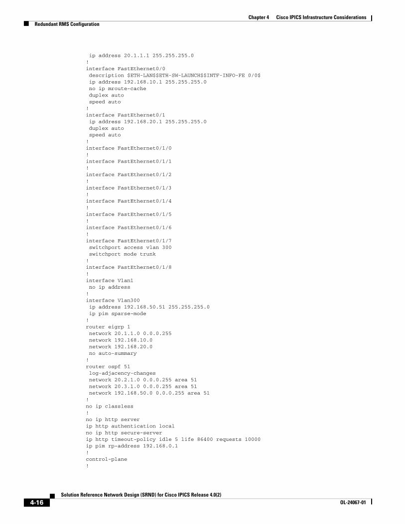
Chapter 4 Cisco IPICS Infrastructure ConsiderationsRedundant RMS Configuration
ip address 20.1.1.1 255.255.255.0!interface FastEthernet0/0 description $ETH-LAN$$ETH-SW-LAUNCH$$INTF-INFO-FE 0/0$ ip address 192.168.10.1 255.255.255.0 no ip mroute-cache duplex auto speed auto!interface FastEthernet0/1 ip address 192.168.20.1 255.255.255.0 duplex auto speed auto!interface FastEthernet0/1/0!interface FastEthernet0/1/1!interface FastEthernet0/1/2!interface FastEthernet0/1/3!interface FastEthernet0/1/4!interface FastEthernet0/1/5!interface FastEthernet0/1/6!interface FastEthernet0/1/7 switchport access vlan 300 switchport mode trunk!interface FastEthernet0/1/8!interface Vlan1 no ip address!interface Vlan300 ip address 192.168.50.51 255.255.255.0 ip pim sparse-mode!router eigrp 1 network 20.1.1.0 0.0.0.255 network 192.168.10.0 network 192.168.20.0 no auto-summary!router ospf 51 log-adjacency-changes network 20.2.1.0 0.0.0.255 area 51 network 20.3.1.0 0.0.0.255 area 51 network 192.168.50.0 0.0.0.255 area 51!no ip classless!no ip http serverip http authentication localno ip http secure-serverip http timeout-policy idle 5 life 86400 requests 10000ip pim rp-address 192.168.0.1!control-plane!
4-16Solution Reference Network Design (SRND) for Cisco IPICS Release 4.0(2)
OL-24067-01
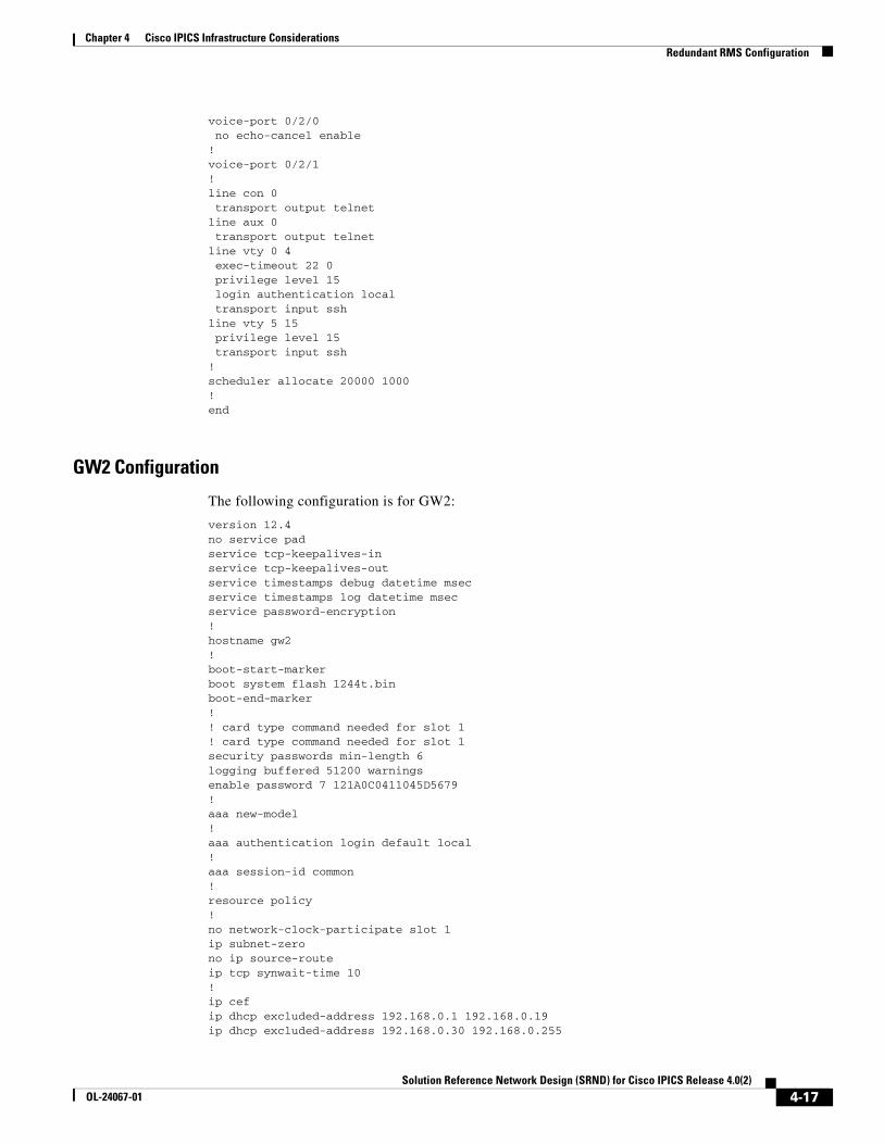
Chapter 4 Cisco IPICS Infrastructure ConsiderationsRedundant RMS Configuration
voice-port 0/2/0 no echo-cancel enable!voice-port 0/2/1!line con 0 transport output telnetline aux 0 transport output telnetline vty 0 4 exec-timeout 22 0 privilege level 15 login authentication local transport input sshline vty 5 15 privilege level 15 transport input ssh!scheduler allocate 20000 1000!end
GW2 Configuration
The following configuration is for GW2:
version 12.4no service padservice tcp-keepalives-inservice tcp-keepalives-outservice timestamps debug datetime msecservice timestamps log datetime msecservice password-encryption!hostname gw2!boot-start-markerboot system flash 1244t.binboot-end-marker!! card type command needed for slot 1! card type command needed for slot 1security passwords min-length 6logging buffered 51200 warningsenable password 7 121A0C0411045D5679!aaa new-model!aaa authentication login default local!aaa session-id common!resource policy!no network-clock-participate slot 1 ip subnet-zerono ip source-routeip tcp synwait-time 10!ip cefip dhcp excluded-address 192.168.0.1 192.168.0.19ip dhcp excluded-address 192.168.0.30 192.168.0.255
4-17Solution Reference Network Design (SRND) for Cisco IPICS Release 4.0(2)
OL-24067-01

Chapter 4 Cisco IPICS Infrastructure ConsiderationsRedundant RMS Configuration
!ip ftp username administratorip ftp password 7 121A0C041104no ip bootp serverip domain name gw2.cisco.comip host appstest50 192.168.0.50ip name-server 39.9.211.2ip name-server 204.127.198.19ip multicast-routing no ip igmp snooping!voice-card 0 dspfarm!voice-card 1 dspfarm!username cisco privilege 15 secret 5 $1$pNyj$Jrgp2.mRgWuks904x3CtR.username ipics privilege 15 password 7 02050D4808095E731F!interface Tunnel3 backup interface Tunnel4 ip address 20.4.1.1 255.255.255.0 ip pim sparse-mode keepalive 7 3 tunnel source Loopback1 tunnel destination 20.1.3.1!interface Tunnel4 ip address 20.5.1.1 255.255.255.0 ip pim sparse-mode keepalive 7 3 tunnel source Loopback1 tunnel destination 20.1.4.1!interface Loopback1 ip address 20.1.2.1 255.255.255.0!interface FastEthernet0/0 description $ETH-LAN$$ETH-SW-LAUNCH$$INTF-INFO-FE 0/0$ ip address 192.168.30.1 255.255.255.0 duplex auto speed auto!interface FastEthernet0/1 ip address 192.168.40.1 255.255.255.0 duplex auto speed auto!interface FastEthernet0/1/0!interface FastEthernet0/1/1!interface FastEthernet0/1/2!interface FastEthernet0/1/3!interface FastEthernet0/1/4!interface FastEthernet0/1/5!interface FastEthernet0/1/6!
4-18Solution Reference Network Design (SRND) for Cisco IPICS Release 4.0(2)
OL-24067-01

Chapter 4 Cisco IPICS Infrastructure ConsiderationsRedundant RMS Configuration
interface FastEthernet0/1/7 switchport access vlan 500 switchport mode trunk!interface FastEthernet0/1/8!interface Vlan1 no ip address!interface Vlan500 ip address 192.168.60.52 255.255.255.0 ip pim sparse-mode!router eigrp 1 network 20.1.2.0 0.0.0.255 network 192.168.30.0 network 192.168.40.0 no auto-summary!router ospf 51 log-adjacency-changes network 20.4.1.0 0.0.0.255 area 51 network 20.5.1.0 0.0.0.255 area 51 network 192.168.60.0 0.0.0.255 area 51!ip classless!!no ip http serverno ip http secure-serverip pim rp-address 192.168.0.1!control-plane!voice-port 0/2/0!voice-port 0/2/1!line con 0 transport output telnetline aux 0 transport output telnetline vty 0 4 exec-timeout 22 0 privilege level 15 login authentication local transport input telnet sshline vty 5 15 privilege level 15 transport input telnet ssh!scheduler allocate 20000 1000!end
GW3 Configuration
The following configuration is for GW3:
version 12.4service timestamps debug datetime msecservice timestamps log datetime msec
4-19Solution Reference Network Design (SRND) for Cisco IPICS Release 4.0(2)
OL-24067-01

Chapter 4 Cisco IPICS Infrastructure ConsiderationsRedundant RMS Configuration
no service password-encryption!hostname GW3!boot-start-markerboot system flash 1244t.binboot-end-marker!! card type command needed for slot 1! card type command needed for slot 1logging buffered 51200 warningsenable password cisco123!aaa new-model!aaa authentication login default local!aaa session-id common!monitor session 1 source interface Fa0/1/7monitor session 1 destination interface Fa0/1/2!resource policy!network-clock-participate slot 1 ip subnet-zero!!ip cefno ip dhcp use vrf connectedip dhcp excluded-address 192.168.1.1ip dhcp excluded-address 192.168.0.1 192.168.0.105ip dhcp excluded-address 192.168.1.2!ip dhcp pool ipics-gw3 network 192.168.1.0 255.255.255.0 domain-name example.com dns-server 68.87.71.226 default-router 192.168.1.1 option 150 ip 192.168.0.50 !ip dhcp pool ipics-gw3-0 network 192.168.0.0 255.255.255.0 domain-name example.com dns-server 38.9.211.2 68.87.221.86 default-router 192.168.0.1 option 150 ip 192.168.0.50 !ip dhcp pool pool-gw3!ip dhcp pool ipics-gw3-100 network 192.168.100.0 255.255.255.0 domain-name example.com dns-server 68.87.71.226 default-router 192.168.100.1 option 150 ip 192.168.0.50 !ip ftp username administratorip ftp password ciscoip domain name cisco.comip multicast-routing ip ssh version 2no ip igmp snooping!
4-20Solution Reference Network Design (SRND) for Cisco IPICS Release 4.0(2)
OL-24067-01

Chapter 4 Cisco IPICS Infrastructure ConsiderationsRedundant RMS Configuration
voice-card 0 dspfarm!voice-card 1 dspfarm!voice service voip sip bind control source-interface Loopback0 bind media source-interface Loopback0!voice class codec 1 codec preference 1 g729r8 codec preference 2 g711ulaw!voice class permanent 1 signal timing oos timeout disabled signal keepalive disabled signal sequence oos no-action! username cisco privilege 15 secret 5 $1$ekF7$FbNJQY8sa228c7eX.YWSx/username ipics privilege 15 password 0 cisco123!interface Loopback0 ip address 192.168.200.1 255.255.255.252 ip pim sparse-mode!interface Vif1 ip address 192.168.200.5 255.255.255.252 ip pim sparse-mode!interface FastEthernet0/0 description $ETH-LAN$$ETH-SW-LAUNCH$$INTF-INFO-FE 0/0$ ip address dhcp ip nat outside ip nat enable ip virtual-reassembly duplex auto speed auto!interface FastEthernet0/1 no ip address shutdown duplex auto speed auto!interface FastEthernet0/1/0 switchport access vlan 100!interface FastEthernet0/1/1 switchport access vlan 100 duplex full speed 100!interface FastEthernet0/1/2 switchport access vlan 100!interface FastEthernet0/1/3 switchport access vlan 100!interface FastEthernet0/1/4 switchport access vlan 400!interface FastEthernet0/1/5
4-21Solution Reference Network Design (SRND) for Cisco IPICS Release 4.0(2)
OL-24067-01
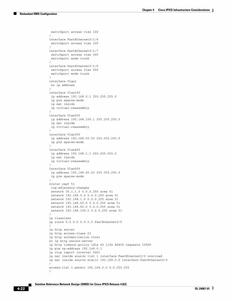
Chapter 4 Cisco IPICS Infrastructure ConsiderationsRedundant RMS Configuration
switchport access vlan 100!interface FastEthernet0/1/6 switchport access vlan 100!interface FastEthernet0/1/7 switchport access vlan 300 switchport mode trunk!interface FastEthernet0/1/8 switchport access vlan 500 switchport mode trunk!interface Vlan1 no ip address!interface Vlan100 ip address 192.168.0.1 255.255.255.0 ip pim sparse-mode ip nat inside ip virtual-reassembly!interface Vlan200 ip address 192.168.100.1 255.255.255.0 ip nat inside ip virtual-reassembly!interface Vlan300 ip address 192.168.50.53 255.255.255.0 ip pim sparse-mode!interface Vlan400 ip address 192.168.1.1 255.255.255.0 ip nat inside ip virtual-reassembly! interface Vlan500 ip address 192.168.60.53 255.255.255.0 ip pim sparse-mode!router ospf 51 log-adjacency-changes network 30.1.1.0 0.0.0.255 area 51 network 192.168.0.0 0.0.0.255 area 51 network 192.168.1.0 0.0.0.255 area 51 network 192.168.50.0 0.0.0.255 area 51 network 192.168.60.0 0.0.0.255 area 51 network 192.168.100.0 0.0.0.255 area 51!ip classlessip route 0.0.0.0 0.0.0.0 FastEthernet0/0!ip http serverip http access-class 23ip http authentication localno ip http secure-serverip http timeout-policy idle 60 life 86400 requests 10000ip pim rp-address 192.168.0.1ip rtcp report interval 5001 ip nat inside source list 1 interface FastEthernet0/0 overloadip nat inside source static 192.168.0.0 interface FastEthernet0/0!access-list 1 permit 192.168.0.0 0.0.255.255!
4-22Solution Reference Network Design (SRND) for Cisco IPICS Release 4.0(2)
OL-24067-01

Chapter 4 Cisco IPICS Infrastructure ConsiderationsRedundant RMS Configuration
control-plane!voice-port 0/2/0 auto-cut-through operation 4-wire type 3 signal lmr lmr e-lead voice lmr led-on no echo-cancel enable timeouts call-disconnect 3 timing hookflash-in 0 timing hangover 80 connection trunk 10100 description Dave-10100!voice-port 0/2/1 auto-cut-through operation 4-wire type 3 signal lmr lmr e-lead voice lmr led-on no echo-cancel enable timeouts call-disconnect 3 timing hookflash-in 0 timing hangover 80 connection trunk 10200 description Dave-10100!dial-peer voice 10100 voip description IPICS1-DP: 239.164.100.100 destination-pattern 10100 session protocol multicast session target ipv4:239.164.100.100:21000 codec g711ulaw vad aggressive!dial-peer voice 10200 voip description IPICS1-DP: 239.164.100.101 destination-pattern 10200 session protocol multicast session target ipv4:239.164.100.101:21000 codec g711ulaw vad aggressive!gateway timer receive-rtcp 5 timer receive-rtp 1200!line con 0line aux 0line vty 0 4 access-class 23 in privilege level 15 transport input telnet sshline vty 5 15 access-class 23 in privilege level 15 transport input telnet ssh!scheduler allocate 20000 1000!end
4-23Solution Reference Network Design (SRND) for Cisco IPICS Release 4.0(2)
OL-24067-01
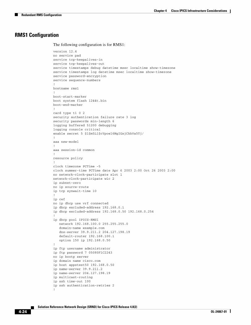
Chapter 4 Cisco IPICS Infrastructure ConsiderationsRedundant RMS Configuration
RMS1 Configuration
The following configuration is for RMS1:
version 12.4no service padservice tcp-keepalives-inservice tcp-keepalives-outservice timestamps debug datetime msec localtime show-timezoneservice timestamps log datetime msec localtime show-timezoneservice password-encryptionservice sequence-numbers!hostname rms1!boot-start-markerboot system flash 1244t.binboot-end-marker!card type t1 0 2security authentication failure rate 3 logsecurity passwords min-length 6logging buffered 51200 debugginglogging console criticalenable secret 5 $1$m5L1$cYpoel6MgIGxjChhVa5Tj/!aaa new-model!aaa session-id common!resource policy!clock timezone PCTime -5clock summer-time PCTime date Apr 6 2003 2:00 Oct 26 2003 2:00no network-clock-participate slot 1 network-clock-participate wic 2 ip subnet-zerono ip source-routeip tcp synwait-time 10!ip cefno ip dhcp use vrf connectedip dhcp excluded-address 192.168.0.1ip dhcp excluded-address 192.168.0.50 192.168.0.254!ip dhcp pool IPICS-RMS1 network 192.168.100.0 255.255.255.0 domain-name example.com dns-server 39.9.211.2 204.127.198.19 default-router 192.168.100.1 option 150 ip 192.168.0.50 !ip ftp username administratorip ftp password 7 05080F1C2243no ip bootp serverip domain name cisco.comip host appstest50 192.168.0.50ip name-server 39.9.211.2ip name-server 204.127.198.19ip multicast-routing ip ssh time-out 100ip ssh authentication-retries 2!
4-24Solution Reference Network Design (SRND) for Cisco IPICS Release 4.0(2)
OL-24067-01

Chapter 4 Cisco IPICS Infrastructure ConsiderationsRedundant RMS Configuration
voice-card 0dspfarm!voice-card 1 dspfarm!voice service voip sip bind media source-interface Loopback3!voice class codec 1 codec preference 1 g729r8 codec preference 2 g711ulaw!voice class permanent 1 signal timing oos timeout disabled signal keepalive disabled signal sequence oos no-action!crypto pki trustpoint TP-self-signed-1491739863 subject-name cn=IOS-Self-Signed-Certificate-1491739863 revocation-check none rsakeypair TP-self-signed-1491739863!no spanning-tree vlan 1username ipics privilege 15 secret 5 $1$rhC4$scpjqfhicEjHL7I48q8150!controller T1 0/2/0 framing esf clock source internal linecode b8zs ds0-group 0 timeslots 24 type e&m-lmr ds0-group 1 timeslots 1 type e&m-lmr ds0-group 2 timeslots 2 type e&m-lmr ds0-group 3 timeslots 3 type e&m-lmr ds0-group 4 timeslots 4 type e&m-lmr ds0-group 5 timeslots 5 type e&m-lmr ds0-group 6 timeslots 6 type e&m-lmr ds0-group 7 timeslots 7 type e&m-lmr ds0-group 8 timeslots 8 type e&m-lmr ds0-group 9 timeslots 9 type e&m-lmr ds0-group 10 timeslots 10 type e&m-lmr ds0-group 11 timeslots 11 type e&m-lmr ds0-group 12 timeslots 12 type e&m-lmr ds0-group 13 timeslots 13 type e&m-lmr ds0-group 14 timeslots 14 type e&m-lmr ds0-group 15 timeslots 15 type e&m-lmr ds0-group 16 timeslots 16 type e&m-lmr ds0-group 17 timeslots 17 type e&m-lmr ds0-group 18 timeslots 18 type e&m-lmr ds0-group 19 timeslots 19 type e&m-lmr ds0-group 20 timeslots 20 type e&m-lmr ds0-group 21 timeslots 21 type e&m-lmr ds0-group 22 timeslots 22 type e&m-lmr ds0-group 23 timeslots 23 type e&m-lmr!controller T1 0/2/1 framing esf linecode b8zs ds0-group 0 timeslots 24 type e&m-lmr ds0-group 1 timeslots 1 type e&m-lmr ds0-group 2 timeslots 2 type e&m-lmr ds0-group 3 timeslots 3 type e&m-lmr ds0-group 4 timeslots 4 type e&m-lmr
4-25Solution Reference Network Design (SRND) for Cisco IPICS Release 4.0(2)
OL-24067-01
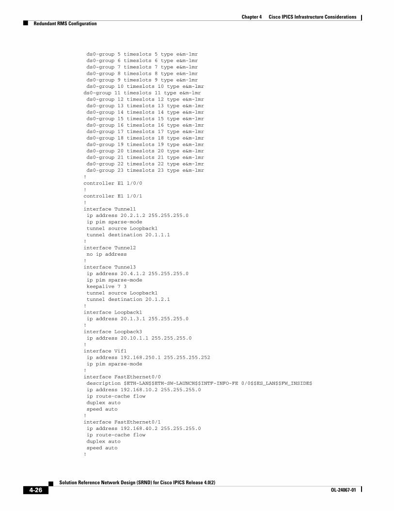
Chapter 4 Cisco IPICS Infrastructure ConsiderationsRedundant RMS Configuration
ds0-group 5 timeslots 5 type e&m-lmr ds0-group 6 timeslots 6 type e&m-lmr ds0-group 7 timeslots 7 type e&m-lmr ds0-group 8 timeslots 8 type e&m-lmr ds0-group 9 timeslots 9 type e&m-lmr ds0-group 10 timeslots 10 type e&m-lmrds0-group 11 timeslots 11 type e&m-lmr ds0-group 12 timeslots 12 type e&m-lmr ds0-group 13 timeslots 13 type e&m-lmr ds0-group 14 timeslots 14 type e&m-lmr ds0-group 15 timeslots 15 type e&m-lmr ds0-group 16 timeslots 16 type e&m-lmr ds0-group 17 timeslots 17 type e&m-lmr ds0-group 18 timeslots 18 type e&m-lmr ds0-group 19 timeslots 19 type e&m-lmr ds0-group 20 timeslots 20 type e&m-lmr ds0-group 21 timeslots 21 type e&m-lmr ds0-group 22 timeslots 22 type e&m-lmr ds0-group 23 timeslots 23 type e&m-lmr!controller E1 1/0/0!controller E1 1/0/1! interface Tunnel1 ip address 20.2.1.2 255.255.255.0 ip pim sparse-mode tunnel source Loopback1 tunnel destination 20.1.1.1!interface Tunnel2 no ip address!interface Tunnel3 ip address 20.4.1.2 255.255.255.0 ip pim sparse-mode keepalive 7 3 tunnel source Loopback1 tunnel destination 20.1.2.1!interface Loopback1 ip address 20.1.3.1 255.255.255.0!interface Loopback3 ip address 20.10.1.1 255.255.255.0!interface Vif1 ip address 192.168.250.1 255.255.255.252 ip pim sparse-mode!interface FastEthernet0/0 description $ETH-LAN$$ETH-SW-LAUNCH$$INTF-INFO-FE 0/0$$ES_LAN$$FW_INSIDE$ ip address 192.168.10.2 255.255.255.0 ip route-cache flow duplex auto speed auto!interface FastEthernet0/1 ip address 192.168.40.2 255.255.255.0 ip route-cache flow duplex auto speed auto!
4-26Solution Reference Network Design (SRND) for Cisco IPICS Release 4.0(2)
OL-24067-01

Chapter 4 Cisco IPICS Infrastructure ConsiderationsRedundant RMS Configuration
interface FastEthernet0/1/0 switchport access vlan 100!interface FastEthernet0/1/1 switchport access vlan 100!interface FastEthernet0/1/2 switchport access vlan 100!interface FastEthernet0/1/3 switchport access vlan 100!interface FastEthernet0/1/4 switchport access vlan 100!interface FastEthernet0/1/5 switchport access vlan 100!interface FastEthernet0/1/6 switchport access vlan 100!interface FastEthernet0/1/7 switchport access vlan 100 shutdown!interface FastEthernet0/1/8 switchport access vlan 300 no cdp enable!interface Vlan1 no ip address no ip redirects no ip unreachables no ip proxy-arp ip route-cache flow!router eigrp 1 network 20.1.3.0 0.0.0.255 network 192.168.10.0 network 192.168.40.0 no auto-summary!router ospf 51 log-adjacency-changes network 20.2.1.0 0.0.0.255 area 51 network 20.4.1.0 0.0.0.255 area 51 network 20.10.1.0 0.0.0.255 area 51 network 192.168.250.0 0.0.0.3 area 51!ip classless!ip http serverip http authentication localno ip http secure-serverip http timeout-policy idle 5 life 86400 requests 10000ip pim rp-address 192.168.0.1ip rtcp report interval 5001 !logging trap debugging!control-plane!dial-peer voice 555 voip voice-class codec 1
4-27Solution Reference Network Design (SRND) for Cisco IPICS Release 4.0(2)
OL-24067-01
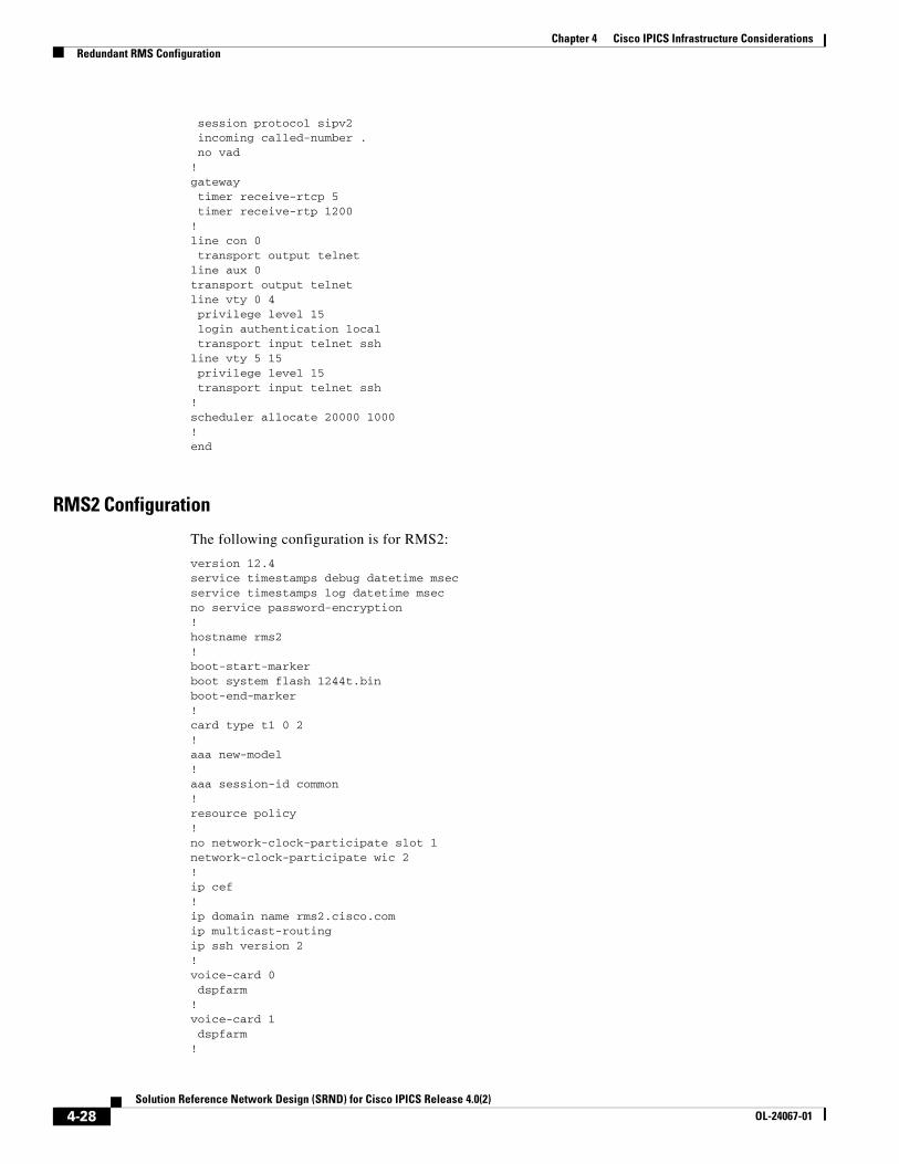
Chapter 4 Cisco IPICS Infrastructure ConsiderationsRedundant RMS Configuration
session protocol sipv2 incoming called-number . no vad!gateway timer receive-rtcp 5 timer receive-rtp 1200!line con 0 transport output telnetline aux 0transport output telnetline vty 0 4 privilege level 15 login authentication local transport input telnet sshline vty 5 15 privilege level 15 transport input telnet ssh!scheduler allocate 20000 1000!end
RMS2 Configuration
The following configuration is for RMS2:
version 12.4service timestamps debug datetime msecservice timestamps log datetime msecno service password-encryption!hostname rms2!boot-start-markerboot system flash 1244t.binboot-end-marker!card type t1 0 2!aaa new-model!aaa session-id common!resource policy!no network-clock-participate slot 1 network-clock-participate wic 2 !ip cef!ip domain name rms2.cisco.comip multicast-routing ip ssh version 2!voice-card 0 dspfarm!voice-card 1 dspfarm!
4-28Solution Reference Network Design (SRND) for Cisco IPICS Release 4.0(2)
OL-24067-01

Chapter 4 Cisco IPICS Infrastructure ConsiderationsRedundant RMS Configuration
voice service voip sip bind media source-interface Loopback3!voice class codec 1 codec preference 1 g729r8 codec preference 2 g711ulaw!voice class permanent 1 signal timing oos timeout disabled signal keepalive disabled signal sequence oos no-action!username ipics privilege 15 secret 5 $1$vrlI$wXX82ATUVJ5nvJrZxwEz/1!controller T1 0/2/0 framing esf clock source internal linecode b8zs cablelength short 133 ds0-group 0 timeslots 24 type e&m-lmr ds0-group 1 timeslots 1 type e&m-lmr ds0-group 2 timeslots 2 type e&m-lmr ds0-group 3 timeslots 3 type e&m-lmr ds0-group 4 timeslots 4 type e&m-lmr ds0-group 5 timeslots 5 type e&m-lmr ds0-group 6 timeslots 6 type e&m-lmr ds0-group 7 timeslots 7 type e&m-lmr ds0-group 8 timeslots 8 type e&m-lmr ds0-group 9 timeslots 9 type e&m-lmr ds0-group 10 timeslots 10 type e&m-lmr ds0-group 11 timeslots 11 type e&m-lmr ds0-group 12 timeslots 12 type e&m-lmr ds0-group 13 timeslots 13 type e&m-lmr ds0-group 14 timeslots 14 type e&m-lmr ds0-group 15 timeslots 15 type e&m-lmr ds0-group 16 timeslots 16 type e&m-lmr ds0-group 17 timeslots 17 type e&m-lmr ds0-group 18 timeslots 18 type e&m-lmr ds0-group 19 timeslots 19 type e&m-lmr ds0-group 20 timeslots 20 type e&m-lmr ds0-group 21 timeslots 21 type e&m-lmr ds0-group 22 timeslots 22 type e&m-lmr ds0-group 23 timeslots 23 type e&m-lmr!controller T1 0/2/1 framing esf linecode b8zs cablelength short 133 ds0-group 0 timeslots 24 type e&m-lmr ds0-group 1 timeslots 1 type e&m-lmr ds0-group 2 timeslots 2 type e&m-lmr ds0-group 3 timeslots 3 type e&m-lmr ds0-group 4 timeslots 4 type e&m-lmr ds0-group 5 timeslots 5 type e&m-lmr ds0-group 6 timeslots 6 type e&m-lmr ds0-group 7 timeslots 7 type e&m-lmr ds0-group 8 timeslots 8 type e&m-lmr ds0-group 9 timeslots 9 type e&m-lmr ds0-group 10 timeslots 10 type e&m-lmr ds0-group 11 timeslots 11 type e&m-lmr ds0-group 12 timeslots 12 type e&m-lmr ds0-group 13 timeslots 13 type e&m-lmr ds0-group 14 timeslots 14 type e&m-lmr
4-29Solution Reference Network Design (SRND) for Cisco IPICS Release 4.0(2)
OL-24067-01
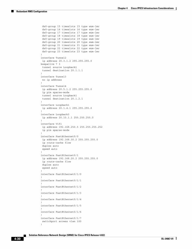
Chapter 4 Cisco IPICS Infrastructure ConsiderationsRedundant RMS Configuration
ds0-group 15 timeslots 15 type e&m-lmr ds0-group 16 timeslots 16 type e&m-lmr ds0-group 17 timeslots 17 type e&m-lmr ds0-group 18 timeslots 18 type e&m-lmr ds0-group 19 timeslots 19 type e&m-lmr ds0-group 20 timeslots 20 type e&m-lmr ds0-group 21 timeslots 21 type e&m-lmr ds0-group 22 timeslots 22 type e&m-lmr ds0-group 23 timeslots 23 type e&m-lmr!interface Tunnel2 ip address 20.3.1.2 255.255.255.0keepalive 7 3 tunnel source Loopback1 tunnel destination 20.1.1.1!interface Tunnel3 no ip address!interface Tunnel4 ip address 20.5.1.2 255.255.255.0 ip pim sparse-mode tunnel source Loopback1 tunnel destination 20.1.2.1!interface Loopback1 ip address 20.1.4.1 255.255.255.0!interface Loopback3 ip address 20.10.1.1 255.255.255.0!interface Vif1 ip address 192.168.250.5 255.255.255.252 ip pim sparse-mode!interface FastEthernet0/0 ip address 192.168.30.2 255.255.255.0 ip route-cache flow duplex auto speed auto!interface FastEthernet0/1 ip address 192.168.20.2 255.255.255.0 ip route-cache flow duplex auto speed auto!interface FastEthernet0/1/0!interface FastEthernet0/1/1!interface FastEthernet0/1/2!interface FastEthernet0/1/3!interface FastEthernet0/1/4!interface FastEthernet0/1/5!interface FastEthernet0/1/6!interface FastEthernet0/1/7 switchport access vlan 100!
4-30Solution Reference Network Design (SRND) for Cisco IPICS Release 4.0(2)
OL-24067-01

Chapter 4 Cisco IPICS Infrastructure ConsiderationsRedundant RMS Configuration
interface FastEthernet0/1/8 switchport access vlan 300!interface Vlan1 no ip address!router eigrp 1 network 20.1.4.0 0.0.0.255 network 192.168.20.0 network 192.168.30.0 no auto-summary!router ospf 51 log-adjacency-changes network 20.3.1.0 0.0.0.255 area 51 network 20.5.1.0 0.0.0.255 area 51 network 20.10.1.0 0.0.0.255 area 51network 192.168.250.4 0.0.0.3 area 51!!no ip http serverno ip http secure-serverip pim rp-address 192.168.0.1ip rtcp report interval 5001 !control-plane!dial-peer voice 555 voip voice-class codec 1 session protocol sipv2 incoming called-number . no vad!gateway timer receive-rtcp 5 timer receive-rtp 1200!line con 0line aux 0line vty 0 4 privilege level 15 transport input sshline vty 5 15 privilege level 15 transport input telnet ssh!scheduler allocate 20000 1000!webvpn context Default_context ssl authenticate verify all ! no inservice!!end
4-31Solution Reference Network Design (SRND) for Cisco IPICS Release 4.0(2)
OL-24067-01
Chapter 4 Cisco IPICS Infrastructure ConsiderationsHigh Availability Considerations
High Availability ConsiderationsThe high availability (HA) functionality in Cisco PICS provides continued service if a primary Cisco IPICS server fails or loses network connectivity. In an HA deployment a backup server operates in a partially hot standby mode, so there is some interruption in service if the primary server fails. There is no automatic failback when a failed server comes back up.
In an HA deployment, one of the Cisco IPICS servers always is in the active role, controlling all system components, including RCSs, RMS components, DMS, LMRGs, radios, GUI users, IDC users, dial-in and dial-out connections, and policies. The other server is in the standby role and most Cisco IPICS processes are initialized on in. The standby server replicates the database and other state changes from the active server. In this way, the standby server is be ready to assume control of the system within 5 minutes after an active server fails.
If the primary IPICS server fails, users and functions are affected as follows:
• IDC users receive uninterrupted service.
• User who are accessing the Cisco IPICS Administration Console and Cisco Unified IP Phone users must manually reconnect to the backup server.
• Dial-in users are dropped, and Cisco IPICS does not call these users back automatically. The users can call back into the system after a relatively short delay.
• Users who are participating in a VTG as a result of being invited by a Cisco IPICS dispatcher (dial-out users) are dropped. A dispatcher can reinvite these users after failover.
• Bulk notifications and policies that are running are dropped and must be manually reinitiated. This situation can cause users to receive duplicate notifications.
HA pairing is established as follows:
1. Immediately following HA setup, the Cisco IPICS server locks until the initial database replication completes. After the initial replication, the server does not wait for replication to complete during startup.
2. The Tomcat server initializes.
3. Service beans, servlets, and web services. are initialized.
4. The Cisco IPICS server reprograms the RMS for any active VTG or SIP connection that is hosted on that RMS. The more DS0s and RMS components that are in a deployment, the longer this process takes, which increases the amount of time needed to go to active state.
For additional information about HA, including configuring HA and understanding an managing various scenarios, refer to the “Configuring and Managing Cisco IPICS High Availability” chapter in Cisco IPICS Server Administration Guide for Release 4.0(2).
Node ManagerThe Node Manager process is responsible for monitoring the state of critical Cisco IPICS subsystems. When a Cisco IPICS server starts, it comes up in standby mode and remains in this mode until it receives the GOACTIVE message from the Node Manager. Then, the server continues initialization and goes into active state.
If HA has been configured, only one server is in active state at any time. The Node Manager elects the server that assumes the active state. When diagnosing server startup issues, see the /opt/cisco/nodemanager/log/nm.log file. This file contains the name of the service that failed.
4-32Solution Reference Network Design (SRND) for Cisco IPICS Release 4.0(2)
OL-24067-01
Chapter 4 Cisco IPICS Infrastructure ConsiderationsHigh Availability Considerations
Note The Node Manager also is involved in non-HA deployments. If a critical service fails heartbeat tests, the Node Manager automatically restarts these services.
Database ReplicationThe database replication processes are independent of the Tomcat process and run constantly in the background. As long as the database is running on both the active and standby servers, and the servers can reach each other, database changes are replicated bidirectionally.
When configuring HA for the first time, Cisco recommends that the secondary server not contain any data. Otherwise there may be unique name collisions that interfere with replication.
SSH Public Keys and TLS CertificatesThe Cisco IPICS active and standby servers use SSH and TLS to securely communicate with each other. During the HA configuration process, both servers automatically exchanges SSH and TLS certificates and public keys to establish trust.
By exchanging SSH public keys, active and standby Cisco IPICS servers can log in to each other via SSH (as ipicsadmin) to perform various automated tasks. During the HA pairing, the active server configures itself, downloads its public SSH key to the standby server, and then invokes a shell script on the standby server that configures the standby server. The standby server performs these same operations on the active server. SSH trust is critical for HA to function properly.
Deployment of Active and Standby ServersIn an HA deployment, Cisco recommends that you:
• Colocate the active and standby servers on the same LAN but on different subnets. This approach helps to ensure that the available bandwidth between the servers is high and that synchronization occurs relatively quickly.
• Use at least a T1 line (1.54 Mbps) between the primary and active servers to allow bandwidth for synchronization of the Cisco IPICS configuration information and database.
• If you require a geographically dispersed active and standby server configuration, ensure that there is at least T1 bandwidth between the servers. A higher bandwidth may be needed if you share large video files in incidents.
• Use the same hardware model for the active and the standby servers. If you do not use the same hardware model, you can use the following parings:
– CPS-MSP-1RU with MCS 7825-H3 or MCS 7825-I3
– CPS-MSP-2RU with MCS 7845-H2
• Be aware that if the active server and standby server have different disk capacities, some data may be lost when data replication or a failover occurs.
4-33Solution Reference Network Design (SRND) for Cisco IPICS Release 4.0(2)
OL-24067-01
Chapter 4 Cisco IPICS Infrastructure ConsiderationsQuality of Service
HA Considerations for the IDCAn IDC obtains the IP address of the standby server from the active Cisco IPICS server during log in. If the IDC detects that it has lost its connection with its current IPICS server, it attempts to connect to the other IPICS server. If that server is in standby mode, the connection attempt fails with no response from that server. If that server is active mode, log in proceeds as usual. If the IDC cannot connect to any IPICS server, it runs in offline mode.
For more information, see Cisco IPICS Dispatch Console User Guide for release 4.0(2).
Quality of ServiceThere are several QoS features that should be enabled so that a Cisco IPICS deployment can deliver toll-quality VoIP QoS. This section provides an overview of these features for Point-to-Point Protocol (PPP) and Frame Relay WAN topologies and for deployments on LAN media.
This section includes these topics:
• QoS Overview, page 4-34
• Cisco IOS Queuing Techniques, page 4-35
• QoS with Frame Relay, page 4-36
• QoS with Point-to-Point Connections, page 4-44
• QoS for a LAN, page 4-45
• QoS at the WAN Edge, page 4-45
• Policing, page 4-46
• Queuing, page 4-46
• Trust Boundaries, page 4-46
QoS OverviewQoS provides consistent voice latency and minimal packet loss. The following recommendations apply to QoS in campus LAN and WAN environments:
• Classify voice RTP streams as expedited forwarding (EF) or IP precedence 5 and place them into a priority queue on all network elements
• Classify voice control traffic as assured forwarding 31 (AF31) or IP precedence 3 and place it into a second queue on all network elements
As you design a VoIP network to deploy real-time applications such as Cisco IPICS, consider the following issues, which can affect voice quality:
• Packet loss—Causes voice clipping and skips. The industry-standard codec algorithms that are used in DSPs can correct for up to 30 ms of lost voice. Cisco VoIP technology uses 20 ms samples of voice payload per VoIP packet. Therefore, for the codec correction algorithms to be effective, only a single packet can be lost during any time. Packet loss can be a significant problem for real-time applications because they are not designed to retransmit packets.
• Delay—Causes either voice quality degradation due to the end-to-end voice latency or packet loss if the delay is variable. If the delay is variable, such as queue delay in bursty data environments, there is a risk of jitter buffer overruns at the receiving end. Longer delays can cause buffer overflow
4-34Solution Reference Network Design (SRND) for Cisco IPICS Release 4.0(2)
OL-24067-01
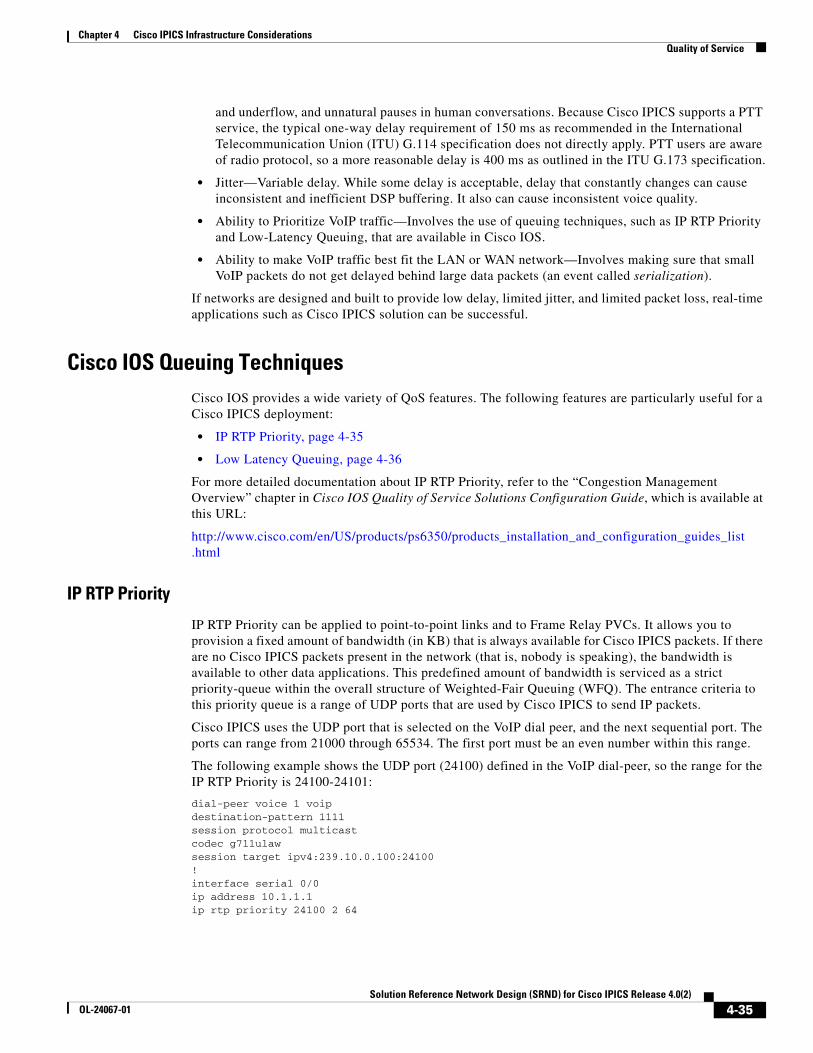
Chapter 4 Cisco IPICS Infrastructure ConsiderationsQuality of Service
and underflow, and unnatural pauses in human conversations. Because Cisco IPICS supports a PTT service, the typical one-way delay requirement of 150 ms as recommended in the International Telecommunication Union (ITU) G.114 specification does not directly apply. PTT users are aware of radio protocol, so a more reasonable delay is 400 ms as outlined in the ITU G.173 specification.
• Jitter—Variable delay. While some delay is acceptable, delay that constantly changes can cause inconsistent and inefficient DSP buffering. It also can cause inconsistent voice quality.
• Ability to Prioritize VoIP traffic—Involves the use of queuing techniques, such as IP RTP Priority and Low-Latency Queuing, that are available in Cisco IOS.
• Ability to make VoIP traffic best fit the LAN or WAN network—Involves making sure that small VoIP packets do not get delayed behind large data packets (an event called serialization).
If networks are designed and built to provide low delay, limited jitter, and limited packet loss, real-time applications such as Cisco IPICS solution can be successful.
Cisco IOS Queuing TechniquesCisco IOS provides a wide variety of QoS features. The following features are particularly useful for a Cisco IPICS deployment:
• IP RTP Priority, page 4-35
• Low Latency Queuing, page 4-36
For more detailed documentation about IP RTP Priority, refer to the “Congestion Management Overview” chapter in Cisco IOS Quality of Service Solutions Configuration Guide, which is available at this URL:
http://www.cisco.com/en/US/products/ps6350/products_installation_and_configuration_guides_list .html
IP RTP Priority
IP RTP Priority can be applied to point-to-point links and to Frame Relay PVCs. It allows you to provision a fixed amount of bandwidth (in KB) that is always available for Cisco IPICS packets. If there are no Cisco IPICS packets present in the network (that is, nobody is speaking), the bandwidth is available to other data applications. This predefined amount of bandwidth is serviced as a strict priority-queue within the overall structure of Weighted-Fair Queuing (WFQ). The entrance criteria to this priority queue is a range of UDP ports that are used by Cisco IPICS to send IP packets.
Cisco IPICS uses the UDP port that is selected on the VoIP dial peer, and the next sequential port. The ports can range from 21000 through 65534. The first port must be an even number within this range.
The following example shows the UDP port (24100) defined in the VoIP dial-peer, so the range for the IP RTP Priority is 24100-24101:
dial-peer voice 1 voipdestination-pattern 1111session protocol multicastcodec g711ulawsession target ipv4:239.10.0.100:24100!interface serial 0/0ip address 10.1.1.1ip rtp priority 24100 2 64
4-35Solution Reference Network Design (SRND) for Cisco IPICS Release 4.0(2)
OL-24067-01
Chapter 4 Cisco IPICS Infrastructure ConsiderationsQuality of Service
Low Latency Queuing
Low-Latency Queuing (LLQ) applies to point-to-point links and to Frame Relay PVCs. LLQ creates a strict priority queue, as does IP RTP Priority, but LLQ applies the strict priority queue as a service-class within Class-Based Weighted Fair Queueing (CBWFQ). The functionality of fixed allocation but dynamic usage is again similar to IP RTP Priority.
A primary difference between IP RTP Priority and LLQ is that LLQ allows the usage of access control lists (ACLs) as the entrance criteria to the priority queue. This capability provides you with flexibility in determining what types of traffic are allowed into the priority queue.
The following example shows how LLQ is used to prioritize Cisco IPICS traffic:
access-list102 permit udp host 10.1.1.1 host 239.10.0.100 range 24100 24101!class-map voicematch access-group 102!policy-map policy1class voicepriority 50!multilink virtual-template 1!interface virtual-template 1ip address 172.17.254.161 255.255.255.248no ip directed-broadcastno ip mroute-cacheservice-policy output policy1ppp multilinkppp multilink fragment-delay 20ppp multilink interleave!interface serial 2/0bandwidth 256no ip addressno ip directed-broadcastencapsulation pppno fair-queueclockrate 256000ppp multilinkmultilink-group 1
QoS with Frame RelayIf you deploy Cisco IPICS in a Frame Relay network, be aware that Frame Relay does not inherently provide QoS. Frame Relay is a best-effort service that expects upper-layer applications to handle retransmissions that occur because of packet loss in the Frame Relay cloud.
Frame Relay typically provides the following parameters:
• Committed Information Rate (CIR)—Amount of bandwidth that the Frame Relay carrier guarantees to be available at all times for a particular PVC. The carrier does not make any guarantees for packets sent above CIR.
• Burst—Maximum amount of data that the Frame Relay carrier allows to be sent on a particular PVC.
To offer the QoS over Frame service, carriers use a technique called over-provisioning bandwidth, in which they sell more bandwidth than they can provide at a particular time. This technique works because not all Frame Relay customers require all available bandwidth at one time.
4-36Solution Reference Network Design (SRND) for Cisco IPICS Release 4.0(2)
OL-24067-01
Chapter 4 Cisco IPICS Infrastructure ConsiderationsQuality of Service
Some Frame Relay carriers also guarantee a Frame Relay network that is always available and that will not drop any customer packets.
A Frame Relay carrier employs a variety of methods to offer a CIR + Burst service, including the following:
• Marking packets with discard eligible (DE) or drop the packets—Because real-time applications such as VoIP use UDP for transport, there is no mechanism for packets to be retransmitted. This situation is not a problem for VoIP because users would not want to hear a dropped word later in a sentence. Packet loss is generally not acceptable for real-time VoIP applications because it can result in choppy audio and garbled speech.
• Buffering all packets above the CIR—Eliminates lost packets, but can introduce jitter and delay because of the depth or rate at which the Frame Relay switches empty buffers.
Table 4-5 summarizes key recommendations when deploying Cisco IPICS on a network with Frame Relay.
Table 4-5 Recommendations when Deploying Cisco IPICS with Frame Relay
Recommendation Technique Comments
To avoid introducing packet loss or jitter into a Cisco IPICS network, make sure that traffic that exceeds the CIR is not sent into a Frame Relay network.
Use the Cisco IOS Frame Relay Traffic Shaping (FRTS) feature.
Allows a router to police traffic on a per-PVC basis so that it does not send any traffic above the CIR.
In a Frame Relay environment, make sure that packets that are sent across a WAN link do not exceed the Committed Information Rate (CIR)
Enable the FRF.12 feature in the Frame network.
FRF.12 is a Frame-Relay-Forum Implementation Agreement that specifies how to fragment and reassemble packets on a Frame Relay network at Layer 2 of the Open Systems Interconnection (OSI) model. By fragmenting large data packets, the smaller Cisco IPICS packets will not be delayed, or subject to serialization, which helps to eliminate delay and jitter of the Cisco IPICS packets. Because the fragmentation and reassembly is done at Layer 2 of the OSI model, it does not adversely effect any upper-layer protocols (such as IPX or Appletalk or IP with DNF bits set) that do not handle fragmentation.
Implement a queuing technique that provides strict priority to Cisco IPICS packets.
Use a technique such as Low-Latency Queuing (LLQ)
The LLQ feature brings strict priority queuing to the Class-Based Weighted Fair Queuing (CBWFQ) method. Strict priority queuing allows delay-sensitive data such as voice to be dequeued and sent first (before packets in other queues are dequeued), giving delay-sensitive data preferential treatment over other traffic.
4-37Solution Reference Network Design (SRND) for Cisco IPICS Release 4.0(2)
OL-24067-01
Chapter 4 Cisco IPICS Infrastructure ConsiderationsQuality of Service
Example
Consider a Cisco IPICS Frame Relay network with the following characteristics:
• Three routers connected through 64 KB Frame Relay PVCs in a hub and spoke topology, with Router-1 being the hub.
• All routers configured to traffic-shape their data and voice on the WAN to CIR, and all routers that are using IP RTP Priority to guarantee QoS for the Cisco IPICS packets.
• Frame Relay broadcast-queue enabled on the serial interfaces.
• One Cisco IPICS channel configured.
Because the broadcast queue is only 40 packets deep by default and Cisco IPICS components (IDC, Cisco Unified IP Phone, RMS) transmit packets at 50 packets/second, the broadcast-queue must be set to prevent voice packets from dropping and to maintain voice quality. The recommended setting for the broadcast-queue is 64 8000 25 (64 queue size, 8,000 bytes per second (64,000 bps), and 25 packets per second).
Frame Relay Broadcast Queue
Broadcast queue is a feature that is used in medium and large IP or IPX networks where routing and service access point (SAP) broadcasts must flow across a Frame Relay network. The broadcast queue is managed independently of the normal interface queue, has its own buffers, and has a configurable size and data rate.
To enable the broadcast queue, use this interface command:
frame-relay broadcast-queue size byte-rate packet-rate
A broadcast queue is given a maximum transmission rate (throughput) limit, which is measured in bytes per second and packets per second. The queue is serviced to ensure that only this maximum is provided. Because the broadcast queue has priority when transmitting at a rate below the configured maximum, it has a guaranteed minimum bandwidth allocation. The two transmission rate limits are intended to avoid flooding the interface with broadcasts. The actual limit in any second is the first rate limit that is reached. Given the transmission rate restriction, additional buffering is required to store broadcast packets.
The broadcast queue can be configured to store a large number of broadcast packets. You should set the queue size to a value that avoids loss of broadcast routing update packets. The exact size depends on the protocol being used and the number of packets required for each update. To be safe, the queue size should be set so that one complete routing update from each protocol and for each data-link connection identifier (DLCI) can be stored. As a general rule, start with 20 packets per DLCI. The byte rate should be less than both of the following:
• n/4 times the minimum remote access rate (measured in bytes per second), where n is the number of DLCIs to which the broadcast must be replicated
• 1/4 the local access rate (measured in bytes per second)
The packet rate is not critical if the byte rate is set conservatively. In general, the packet rate should be set assuming 250-byte packets. The frame-relay broadcast-queue command defaults are as follows:
• Size—64 packets
• Byte-rate—256000 bytes per second
• Packet-rate—36 packets per second
4-38Solution Reference Network Design (SRND) for Cisco IPICS Release 4.0(2)
OL-24067-01
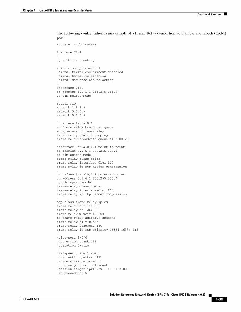
Chapter 4 Cisco IPICS Infrastructure ConsiderationsQuality of Service
The following configuration is an example of a Frame Relay connection with an ear and mouth (E&M) port:
Router-1 (Hub Router)
hostname FR-1!ip multicast-routing!voice class permanent 1 signal timing oos timeout disabled signal keepalive disabled signal sequence oos no-action!interface Vif1ip address 1.1.1.1 255.255.255.0ip pim sparse-mode!router ripnetwork 1.1.1.0network 5.5.5.0network 5.5.6.0!interface Serial0/0no frame-relay broadcast-queueencapsulation frame-relayframe-relay traffic-shapingframe-relay broadcast-queue 64 8000 250!interface Serial0/0.1 point-to-pointip address 5.5.5.1 255.255.255.0ip pim sparse-modeframe-relay class ipicsframe-relay interface-dlci 100frame-relay ip rtp header-compression!interface Serial0/0.1 point-to-pointip address 5.5.6.1 255.255.255.0ip pim sparse-modeframe-relay class ipicsframe-relay interface-dlci 100frame-relay ip rtp header-compression!map-class frame-relay ipicsframe-relay cir 128000frame-relay bc 1280frame-relay mincir 128000no frame-relay adaptive-shapingframe-relay fair-queueframe-relay fragment 160frame-relay ip rtp priority 16384 16384 128!voice-port 1/0/0 connection trunk 111 operation 4-wire!dial-peer voice 1 voip destination-pattern 111 voice class permanent 1 session protocol multicast session target ipv4:239.111.0.0:21000 ip precedence 5!
4-39Solution Reference Network Design (SRND) for Cisco IPICS Release 4.0(2)
OL-24067-01

Chapter 4 Cisco IPICS Infrastructure ConsiderationsQuality of Service
Router-2 (Spoke Router)
hostname FR-2!ip multicast-routing!voice class permanent 1 signal timing oos timeout disabled signal keepalive disabled signal sequence oos no-action!interface Vif1ip address 1.1.2.1 255.255.255.0ip pim sparse-mode!router ripnetwork 1.1.2.0network 5.5.5.0!interface Serial0/0no frame-relay broadcast-queueencapsulation frame-relayframe-relay traffic-shapingframe-relay broadcast-queue 64 8000 250!interface Serial0/0.1 point-to-pointip address 5.5.5.2 255.255.255.0ip pim sparse-modeframe-relay class ipicsframe-relay interface-dlci 100frame-relay ip rtp header-compression!map-class frame-relay ipicsframe-relay cir 128000frame-relay bc 1280frame-relay mincir 128000no frame-relay adaptive-shapingframe-relay fair-queueframe-relay fragment 160frame-relay ip rtp priority 16384 16384 128!voice-port 1/0/0 connection trunk 111 operation 4-wire!dial-peer voice 1 voip destination-pattern 111 voice class permanent 1 session protocol multicast session target ipv4:239.111.0.0:21000 ip precedence 5!
Router-3 (Spoke Router)
hostname FR-3!ip multicast-routing!voice class permanent 1 signal timing oos timeout disabled signal keepalive disabled signal sequence oos no-action!
4-40Solution Reference Network Design (SRND) for Cisco IPICS Release 4.0(2)
OL-24067-01
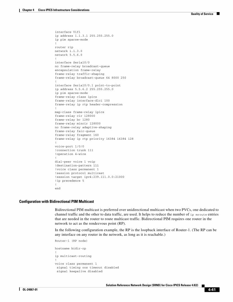
Chapter 4 Cisco IPICS Infrastructure ConsiderationsQuality of Service
interface Vif1ip address 1.1.3.1 255.255.255.0ip pim sparse-mode!router ripnetwork 1.1.3.0network 5.5.6.0!interface Serial0/0no frame-relay broadcast-queueencapsulation frame-relayframe-relay traffic-shapingframe-relay broadcast-queue 64 8000 250!interface Serial0/0.1 point-to-pointip address 5.5.6.2 255.255.255.0ip pim sparse-modeframe-relay class ipicsframe-relay interface-dlci 100frame-relay ip rtp header-compression!map-class frame-relay ipicsframe-relay cir 128000frame-relay bc 1280frame-relay mincir 128000no frame-relay adaptive-shapingframe-relay fair-queueframe-relay fragment 160frame-relay ip rtp priority 16384 16384 128!voice-port 1/0/0!connection trunk 111!operation 4-wire!dial-peer voice 1 voip!destination-pattern 111!voice class permanent 1!session protocol multicast!session target ipv4:239.111.0.0:21000!ip precedence 5!end
Configuration with Bidirectional PIM Multicast
Bidirectional PIM multicast is preferred over unidirectional multicast when two PVCs, one dedicated to channel traffic and the other to data traffic, are used. It helps to reduce the number of ip mroute entries that are needed in the router to route multicast traffic. Bidirectional PIM requires one router in the network to act as the rendezvous point (RP).
In the following configuration example, the RP is the loopback interface of Router-1. (The RP can be any interface on any router in the network, as long as it is reachable.)
Router-1 (RP node)
hostname bidir-rp!ip multicast-routing!voice class permanent 1 signal timing oos timeout disabled signal keepalive disabled
4-41Solution Reference Network Design (SRND) for Cisco IPICS Release 4.0(2)
OL-24067-01

Chapter 4 Cisco IPICS Infrastructure ConsiderationsQuality of Service
signal sequence oos no-action!voice class permanent 2 signal timing oos timeout disabled signal keepalive disabled signal sequence oos no-action]!interface Loopback1ip address 10.10.2.1 255.255.255.0ip pim sparse-mode!interface Vif1ip address 10.1.2.1 255.255.255.0ip pim sparse-modeload-interval 30!router ripnetwork 10.1.2.0network 10.100.0.0network 10.101.0.0!interface Serial0/0no ip addressencapsulation frame-relay IETFload-interval 30no fair-queueframe-relay traffic-shapingframe-relay lmi-type cisco!interface Serial0/0.1 point-to-pointdescription channel pvcbandwidth 256ip address 10.100.100.1 255.255.255.0ip pim sparse-modeframe-relay interface-dlci 100class channel!interface Serial0/0.2 point-to-pointdescription data pvcip address 10.101.101.1 255.255.255.0frame-relay interface-dlci 200class data!ip classlessip pim bidir-enableip pim rp-address 10.10.2.1 10 override bidir!map-class frame-relay channelframe-relay cir 128000frame-relay bc 1000frame-relay be 0no frame-relay adaptive-shaping!map-class frame-relay dataframe-relay cir 768000frame-relay mincir 128000frame-relay adaptive-shaping becn!voice-port 1/0/0 voice class permanent 1 timeouts wait-release 3 timing dialout-delay 70 connection trunk 111 operation 4-wire
4-42Solution Reference Network Design (SRND) for Cisco IPICS Release 4.0(2)
OL-24067-01

Chapter 4 Cisco IPICS Infrastructure ConsiderationsQuality of Service
signal lmr!dial-peer voice 1 voipdestination-pattern 111session protocol multicastsession target ipv4:239.111.0.0:21000ip precedence 5!end
Router-2 (non-RP node)
hostname bidir-2!ip multicast-routing!voice class permanent 1 signal timing oos timeout disabled signal keepalive disabled signal sequence oos no-action!voice class permanent 2 signal timing oos timeout disabled signal keepalive disabled signal sequence oos no-action!interface Loopback1ip address 10.10.3.1 255.255.255.0ip pim sparse-mode!interface Vif1ip address 10.1.3.1 255.255.255.0ip pim sparse-modeload-interval 30!router ripnetwork 10.1.3.0network 10.100.0.0network 10.101.0.0!interface Serial0/0no ip addressencapsulation frame-relay IETFload-interval 30no fair-queueframe-relay traffic-shapingframe-relay lmi-type cisco!interface Serial0/0.1 point-to-pointdescription channel pvcbandwidth 256ip address 10.100.100.2 255.255.255.0ip pim sparse-modeframe-relay interface-dlci 100class channel!interface Serial0/0.2 point-to-pointdescription data pvcip address 10.101.101.2 255.255.255.0frame-relay interface-dlci 200class data!ip classlessip route 10.10.2.1 255.255.255.255 Serial0/0.1
4-43Solution Reference Network Design (SRND) for Cisco IPICS Release 4.0(2)
OL-24067-01
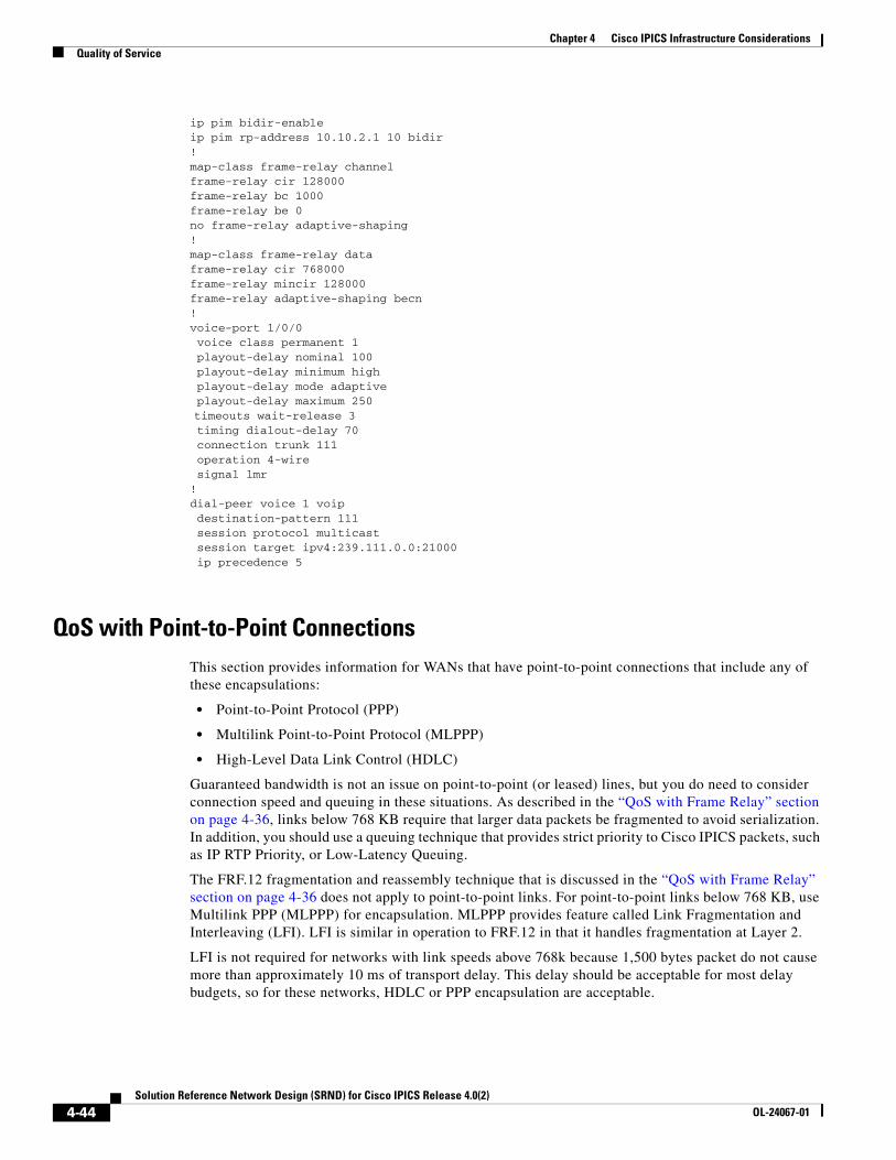
Chapter 4 Cisco IPICS Infrastructure ConsiderationsQuality of Service
ip pim bidir-enableip pim rp-address 10.10.2.1 10 bidir!map-class frame-relay channelframe-relay cir 128000frame-relay bc 1000frame-relay be 0no frame-relay adaptive-shaping!map-class frame-relay dataframe-relay cir 768000frame-relay mincir 128000frame-relay adaptive-shaping becn!voice-port 1/0/0 voice class permanent 1 playout-delay nominal 100 playout-delay minimum high playout-delay mode adaptive playout-delay maximum 250 timeouts wait-release 3 timing dialout-delay 70 connection trunk 111 operation 4-wire signal lmr!dial-peer voice 1 voip destination-pattern 111 session protocol multicast session target ipv4:239.111.0.0:21000 ip precedence 5
QoS with Point-to-Point ConnectionsThis section provides information for WANs that have point-to-point connections that include any of these encapsulations:
• Point-to-Point Protocol (PPP)
• Multilink Point-to-Point Protocol (MLPPP)
• High-Level Data Link Control (HDLC)
Guaranteed bandwidth is not an issue on point-to-point (or leased) lines, but you do need to consider connection speed and queuing in these situations. As described in the “QoS with Frame Relay” section on page 4-36, links below 768 KB require that larger data packets be fragmented to avoid serialization. In addition, you should use a queuing technique that provides strict priority to Cisco IPICS packets, such as IP RTP Priority, or Low-Latency Queuing.
The FRF.12 fragmentation and reassembly technique that is discussed in the “QoS with Frame Relay” section on page 4-36 does not apply to point-to-point links. For point-to-point links below 768 KB, use Multilink PPP (MLPPP) for encapsulation. MLPPP provides feature called Link Fragmentation and Interleaving (LFI). LFI is similar in operation to FRF.12 in that it handles fragmentation at Layer 2.
LFI is not required for networks with link speeds above 768k because 1,500 bytes packet do not cause more than approximately 10 ms of transport delay. This delay should be acceptable for most delay budgets, so for these networks, HDLC or PPP encapsulation are acceptable.
4-44Solution Reference Network Design (SRND) for Cisco IPICS Release 4.0(2)
OL-24067-01
Chapter 4 Cisco IPICS Infrastructure ConsiderationsQuality of Service
The following example shows configuring MLPPP with LFI:
interface Serial0bandwidth 64no ip addressno ip directed-broadcastencapsulation pppno ip route-cacheno ip mroute-cacheno fair-queueppp multilinkmultilink-group 1!interface Multilink 1ip address 10.1.1.1 255.255.255.252no ip directed-broadcastno ip route-cacheip rtp header-compression iphc-formatip tcp header-compression iphc-formatno ip mroute-cachefair-queue 64 256 1000ppp multilinkppp multilink fragment-delay 10ppp multilink interleavemultilink-group 1ip rtp priority 16384 16383 30!
QoS for a LANWhen you deploy QoS in a LAN, classify and mark applications as close to their sources as possible. For example, implement QoS in a Cisco Catalyst switch for IDCs or Cisco Unified IP Phones that connect to the Cisco IPICS server via multicast. For LMRs, implement QoS in the dial peer that is configured for the E&M port that connects to the radios
To classify and mark applications, follow these recommendations:
• Use Differentiated Services Code Point (DSCP) markings whenever possible.
• Follow standards-based DSCP per-hop behaviors (PHB) to ensure interoperation and provide for future expansion. These standards include:
– RFC 2474 Class Selector Codepoints
– RFC 2597 Assured Forwarding Classes
– RFC 3246 Expedited Forwarding.
Note Because SIP-based IDCs are in the data Virtual LAN (VLAN) instead of in the voice VLAN, Cisco IPICS automatically pushes QoS configuration for IDCs to the RMS.
QoS at the WAN EdgeQoS should be configured at the WAN edge so that QoS settings are forwarded to the next-hop router. When you configure QoS at the WAN edge, follow these recommendations:
• If the combined WAN circuit-rate is significantly below 100 Mbps, enable egress shaping on the Cisco Catalyst switches (when supported)
4-45Solution Reference Network Design (SRND) for Cisco IPICS Release 4.0(2)
OL-24067-01
Chapter 4 Cisco IPICS Infrastructure ConsiderationsQuality of Service
• If the combined WAN circuit-rate is significantly below 100 Mbps and the Cisco Catalyst switch does not support shaping, enable egress policing (when supported)
PolicingPolicing is configured so that traffic of a certain class that exceeds the allocated bandwidth is marked as discard eligible (DE) or is dropped, so it prevents denial of service (DoS) or a virus attacks. When you configure policing, follow theses recommendations.
• Police traffic flows as close to their sources as possible.
• Perform markdown according to standards-based rules, whenever supported.
• RFC 2597 specifies how Assured Forwarding traffic classes should be marked down (AF11 > AF12 > AF13). You should follow this specification when DSCP-Based WRED is supported on egress queues.
• Cisco Catalyst platforms do not support DSCP-Based WRED. Scavenger-class remarking is a viable alternative.
• Non-AF classes do not have a markdown scheme defined in standards, so Scavenger-class remarking is a viable option.
• Profile applications to determine what constitutes “normal” or “abnormal” flows (within a 95% confidence interval).
• Deploy campus access-edge policers to remark abnormal traffic to Scavenger.
• Deploy a second-line of defense at the distribution-layer via per-user microflow policing.
• Provision end-to-end “less-than-best-Effort” scavenger-class queuing policies.
QueuingQueuing is a method of buffering traffic so that the traffic does not overflow the allocated bandwidth on a WAN. To provide service guarantees, enable queuing at any node that has the potential for congestion.
When you enable queuing, follow these recommendations:
• Reserve at least 25% of the bandwidth of a link for the default best effort class.
• Limit the amount of strict-priority queuing to 33% of the capacity of a link.
• Whenever a Scavenger queuing class is enabled, assigned to it a minimal amount of bandwidth.
• To ensure consistent per-hop behavior (PHB), configure consistent queuing policies in the campus, WAN, and VPN, according to platform capabilities.
• Enable WRED on all TCP flows, if supported. DSCP-based WRED is recommended.
Trust BoundariesThe Cisco IPICS QoS infrastructure is defined by using a trust boundary. For detailed information about trust boundary concepts, refer to Cisco Unified Communications SRND Based on Cisco Unified CallManager 4.x, which is available at this URL:
http://www.cisco.com/application/pdf/en/us/guest/products/ps5820/c2001/ccmigration_ 09186a00804474f2.pdf
4-46Solution Reference Network Design (SRND) for Cisco IPICS Release 4.0(2)
OL-24067-01
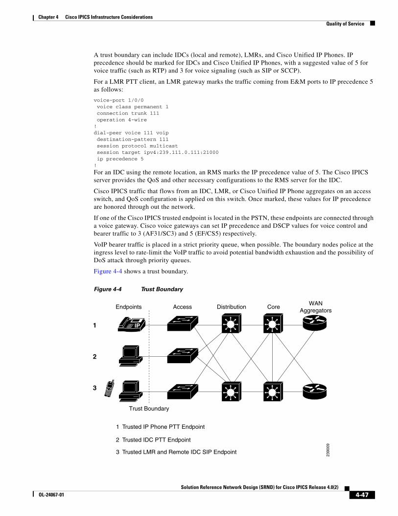
Chapter 4 Cisco IPICS Infrastructure ConsiderationsQuality of Service
A trust boundary can include IDCs (local and remote), LMRs, and Cisco Unified IP Phones. IP precedence should be marked for IDCs and Cisco Unified IP Phones, with a suggested value of 5 for voice traffic (such as RTP) and 3 for voice signaling (such as SIP or SCCP).
For a LMR PTT client, an LMR gateway marks the traffic coming from E&M ports to IP precedence 5 as follows:
voice-port 1/0/0 voice class permanent 1 connection trunk 111 operation 4-wire!dial-peer voice 111 voip destination-pattern 111 session protocol multicast session target ipv4:239.111.0.111:21000 ip precedence 5!
For an IDC using the remote location, an RMS marks the IP precedence value of 5. The Cisco IPICS server provides the QoS and other necessary configurations to the RMS server for the IDC.
Cisco IPICS traffic that flows from an IDC, LMR, or Cisco Unified IP Phone aggregates on an access switch, and QoS configuration is applied on this switch. Once marked, these values for IP precedence are honored through out the network.
If one of the Cisco IPICS trusted endpoint is located in the PSTN, these endpoints are connected through a voice gateway. Cisco voice gateways can set IP precedence and DSCP values for voice control and bearer traffic to 3 (AF31/SC3) and 5 (EF/CS5) respectively.
VoIP bearer traffic is placed in a strict priority queue, when possible. The boundary nodes police at the ingress level to rate-limit the VoIP traffic to avoid potential bandwidth exhaustion and the possibility of DoS attack through priority queues.
Figure 4-4 shows a trust boundary.
Figure 4-4 Trust Boundary
IP
Endpoints Access Distribution CoreWAN
Aggregators
Trust Boundary
1
2
3
1 Trusted IP Phone PTT Endpoint
2 Trusted IDC PTT Endpoint
3 Trusted LMR and Remote IDC SIP Endpoint
2390
09
4-47Solution Reference Network Design (SRND) for Cisco IPICS Release 4.0(2)
OL-24067-01
Chapter 4 Cisco IPICS Infrastructure ConsiderationsVPN in Deployment Scenarios
The following example shows access layer QoS configuration for a Cisco Catalyst 3550:
CAT3550(config)#mls qos map policed-dscp 0 24 46 to 8! Excess traffic marked 0 or CS3 or EF will be remarked to CS1CAT3550(config)#CAT3550(config)#class-map match-all IPICS-VOICECAT3550(config-cmap)# match access-group name IPICS-VOICECAT3550(config)#policy-map IPICS-PTTCCAT3550(config-pmap)#class IPICS-VOICECAT3550(config-pmap-c)# set ip dscp 46 ! VoIP is marked to DSCP EFCAT3550(config-pmap-c)# police 128000 8000 exceed-action policed-dscp-transmit! Out-of-profile IPICS VoIP (G711) is marked down to Scavenger (CS1)CAT3550(config-pmap-c)#class IPICS-SIGNALINGCAT3550(config-pmap-c)# set ip dscp 24! Signalling is marked to DSCP CS3CAT3550(config-pmap-c)# police 32000 8000 exceed-action policed-dscp-transmit! Out-of-profile Signalling is marked down to Scavenger (CS1)CAT3550(config-pmap-c)#class class-defaultCAT3550(config-pmap-c)# set ip dscp 0CAT3550(config-pmap-c)# police 5000000 8000 exceed-action policed-dscp-transmit! Out-of-profile data traffic is marked down to Scavenger (CS1) 50000 (Depends on per customer design and requirements)CAT3550(config-pmap-c)# exitCAT3550(config-pmap)#exitCAT3550(config)#CAT3550(config)#interface range FastEthernet0/1 - 48CAT3550(config-if)# service-policy input IPICS-PTTC ! Attaching the policy map IPICS-PTTC to the interface rangeCAT3550(config-if)#exitCAT3550(config)#CAT3550(config)#ip access-list extended IPICS-VOICE! Extended ACL for the IPICS Address/Port rangesCAT3550(config-ext-nacl)# permit udp 233.0.0.0 0.255.255.255 233.0.0.0 0.255.255.255 range 21000 65534permit udp 233.0.0.0 0.255.255.255 239.0.0.0 0.255.255.255 range 21000 65534permit udp 239.0.0.0 0.255.255.255 233.0.0.0 0.255.255.255 range 21000 65534permit udp 239.0.0.0 0.255.255.255 239.0.0.0 0.255.255.255 range 21000 65534CAT3550(config-ext-nacl)#ip access-list extended IPICS-SIGNALING! Extended ACL for the remote IDC clientsCAT3550(config-ext-nacl)# permit udp <RMS IP Address> <Any > eq 5060 ! Extended ACL for the PSTN clientsCAT3550(config-ext-nacl)# permit udp <VoiceGW IP Address> <Any > eq 5060CAT3550(config-ext-nacl)# permit tcp <Voice GW IP Address> <Any > eq 1720CAT3550(config-ext-nacl)#endCAT3550#
VPN in Deployment ScenariosA Cisco IPICS deployment can include a VPN implementation for the IDC and for mobile clients.
For the IDC, the IDC client PC must run a VPN client if the PC is not connected to a network that can reach the network on which the Cisco IPICS server is installed.
For the iPhone mobile client, audio cannot be transmitted bidirectionally on a 3G network because certain providers block the audio on their data networks. Implementing a VPN tunnel between the Cisco IPICS server and the mobile client allows bidirectional transmission of audio. (Bidirectional audio quality depends on the service provider.)
4-48Solution Reference Network Design (SRND) for Cisco IPICS Release 4.0(2)
OL-24067-01
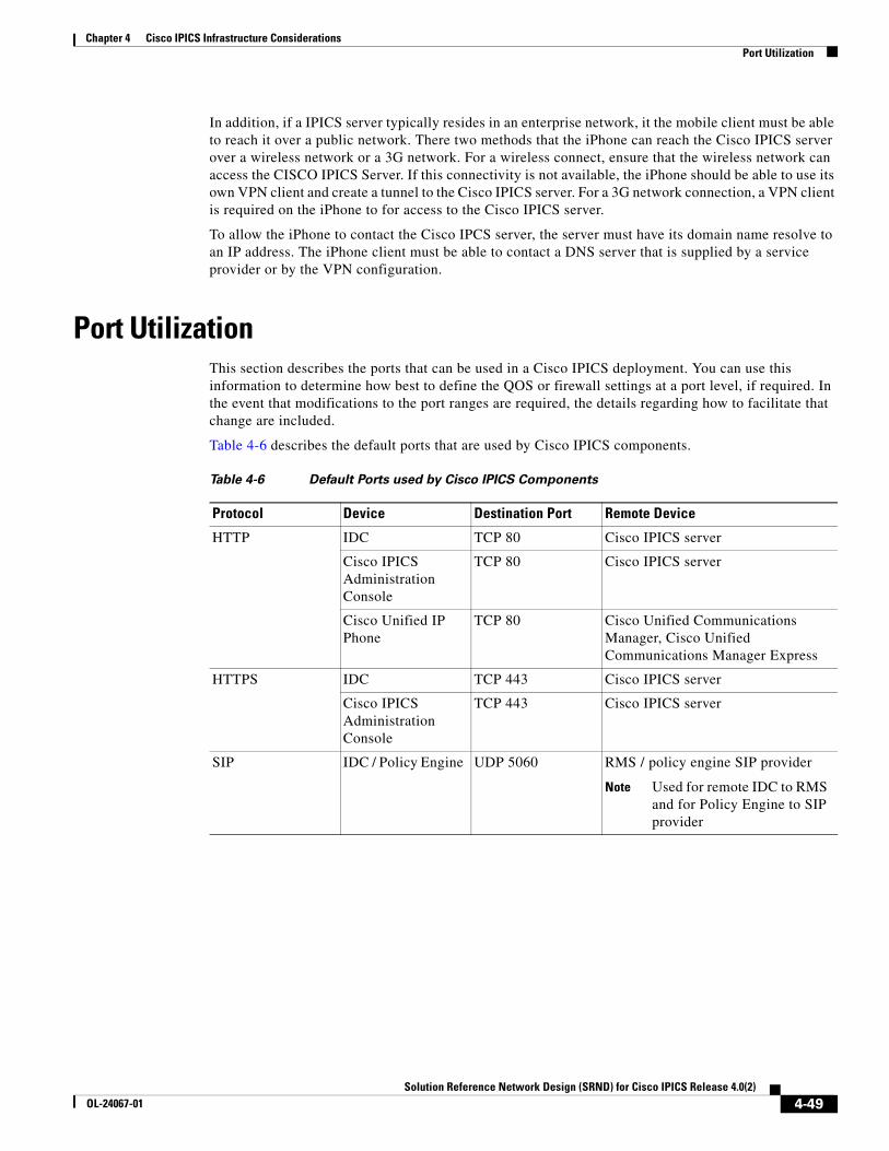
Chapter 4 Cisco IPICS Infrastructure ConsiderationsPort Utilization
In addition, if a IPICS server typically resides in an enterprise network, it the mobile client must be able to reach it over a public network. There two methods that the iPhone can reach the Cisco IPICS server over a wireless network or a 3G network. For a wireless connect, ensure that the wireless network can access the CISCO IPICS Server. If this connectivity is not available, the iPhone should be able to use its own VPN client and create a tunnel to the Cisco IPICS server. For a 3G network connection, a VPN client is required on the iPhone to for access to the Cisco IPICS server.
To allow the iPhone to contact the Cisco IPCS server, the server must have its domain name resolve to an IP address. The iPhone client must be able to contact a DNS server that is supplied by a service provider or by the VPN configuration.
Port UtilizationThis section describes the ports that can be used in a Cisco IPICS deployment. You can use this information to determine how best to define the QOS or firewall settings at a port level, if required. In the event that modifications to the port ranges are required, the details regarding how to facilitate that change are included.
Table 4-6 describes the default ports that are used by Cisco IPICS components.
Table 4-6 Default Ports used by Cisco IPICS Components
Protocol Device Destination Port Remote Device
HTTP IDC TCP 80 Cisco IPICS server
Cisco IPICS Administration Console
TCP 80 Cisco IPICS server
Cisco Unified IP Phone
TCP 80 Cisco Unified Communications Manager, Cisco Unified Communications Manager Express
HTTPS IDC TCP 443 Cisco IPICS server
Cisco IPICS Administration Console
TCP 443 Cisco IPICS server
SIP IDC / Policy Engine UDP 5060 RMS / policy engine SIP provider
Note Used for remote IDC to RMS and for Policy Engine to SIP provider
4-49Solution Reference Network Design (SRND) for Cisco IPICS Release 4.0(2)
OL-24067-01
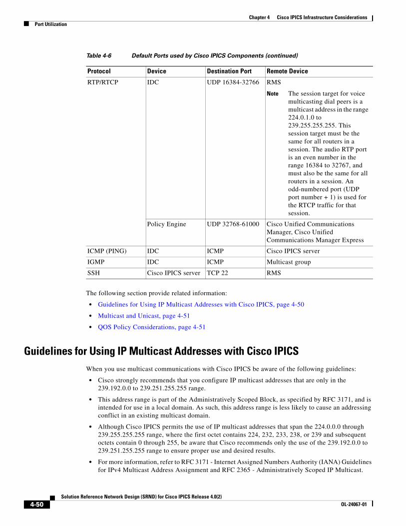
Chapter 4 Cisco IPICS Infrastructure ConsiderationsPort Utilization
The following section provide related information:
• Guidelines for Using IP Multicast Addresses with Cisco IPICS, page 4-50
• Multicast and Unicast, page 4-51
• QOS Policy Considerations, page 4-51
Guidelines for Using IP Multicast Addresses with Cisco IPICSWhen you use multicast communications with Cisco IPICS be aware of the following guidelines:
• Cisco strongly recommends that you configure IP multicast addresses that are only in the 239.192.0.0 to 239.251.255.255 range.
• This address range is part of the Administratively Scoped Block, as specified by RFC 3171, and is intended for use in a local domain. As such, this address range is less likely to cause an addressing conflict in an existing multicast domain.
• Although Cisco IPICS permits the use of IP multicast addresses that span the 224.0.0.0 through 239.255.255.255 range, where the first octet contains 224, 232, 233, 238, or 239 and subsequent octets contain 0 through 255, be aware that Cisco recommends only the use of the 239.192.0.0 to 239.251.255.255 range to ensure proper use and desired results.
• For more information, refer to RFC 3171 - Internet Assigned Numbers Authority (IANA) Guidelines for IPv4 Multicast Address Assignment and RFC 2365 - Administratively Scoped IP Multicast.
RTP/RTCP IDC UDP 16384-32766 RMS
Note The session target for voice multicasting dial peers is a multicast address in the range 224.0.1.0 to 239.255.255.255. This session target must be the same for all routers in a session. The audio RTP port is an even number in the range 16384 to 32767, and must also be the same for all routers in a session. An odd-numbered port (UDP port number + 1) is used for the RTCP traffic for that session.
Policy Engine UDP 32768-61000 Cisco Unified Communications Manager, Cisco Unified Communications Manager Express
ICMP (PING) IDC ICMP Cisco IPICS server
IGMP IDC ICMP Multicast group
SSH Cisco IPICS server TCP 22 RMS
Table 4-6 Default Ports used by Cisco IPICS Components (continued)
Protocol Device Destination Port Remote Device
4-50Solution Reference Network Design (SRND) for Cisco IPICS Release 4.0(2)
OL-24067-01
Chapter 4 Cisco IPICS Infrastructure ConsiderationsSecuring the Cisco IPICS Infrastructure
Multicast and UnicastWhen the Cisco IPICS solution is configured, channels are assigned static multicast IP addresses and port pairs. Ports that are assigned to an IDC must be within the acceptable port range for an IDC.In addition, the multicast addresses that are defined in the multicast address pool for dynamic allocation must be within the acceptable port range for an IDC.
When an IDC connects by using the remote location, it establishes a unicast media connection to an RMS. The UDP port that is assigned for the media connection will be allocated from within the supported range.
QOS Policy ConsiderationsWhen defining QOS policies that will be assigned to a UDP port range, using Source Host and Destination Host addresses of ANY allows the QOS policy to be properly set based on the IDC UDP port range. In this case, UDP ports that are assigned by the RMS are not considered, which helps to simplify the QOS policies.
Securing the Cisco IPICS InfrastructureThe following sections provide information about providing system security for Cisco IPICS:
• Secure Socket Layer, page 4-51
• Cisco Security Agent, page 4-51
• Firewalls and Access Control Lists, page 4-52
• Other Security Recommendations, page 4-52
Secure Socket LayerCisco IPICS uses Secure Socket Layer (SSL) to encrypt communications between an IDC and the Cisco IPICS server. The browser with which you access the Cisco IPICS Administration Console uses HTTPS. To enforce SSL, you must install a certificate on the Cisco IPICS server. You can use a self-signed certificate or, to impose additional security, you can purchase and set up a digitally-signed certificate. In addition, the RMS control uses SSH as a client.
For additional information, refer to the “Installing Third Party Certificates on the Cisco IPICS Server” section in Cisco IPICS Server Installation and Upgrade Guide, Release 4.0(2).
Cisco Security AgentThe Cisco Security Agent (CSA), which is optionally available separately from Cisco IPICS, provides intrusion detection and prevention for the Cisco IPICS server and for the IDC. Instead of focusing on attacks, CSA focuses on preventing malicious and undesired activities on the host. CSA detects and blocks the damaging activities. CSA ships with pre-defined policies that prevent most types of malicious activity from occurring. Since malicious activity is always undesired, security at this level is very inexpensive to deploy. Little or no environment tuning is required. In rare cases, critical business applications can be affected if CSA prevents your web server from adding a new user account
4-51Solution Reference Network Design (SRND) for Cisco IPICS Release 4.0(2)
OL-24067-01
Chapter 4 Cisco IPICS Infrastructure ConsiderationsCisco IPICS Network Management System
Firewalls and Access Control ListsUse a firewall and access control lists (ACLs) in front of the Cisco IPICS server and other Cisco IPICS components to add an extra layer of security. For example, you can use a firewall or an ACL to allow only call control and management packets to reach the Cisco IPICS server, and block unnecessary traffic such as Telnet or TFTP traffic. You can use ACLs to allow only the source addresses that are supposed to access your network.
When you use a firewall, it must support state-full inspection of voice signaling protocol. Cisco IPICS uses UDP ports 21000–65534, and a firewall must only open the ports needed to support for this application. In addition, make sure that the firewall supports application layer gateway (ALG) capabilities. ALG inspects signaling packets to discover what UDP port an RTP stream is going to use and dynamically opens a pinhole for that UDP port.
Other Security RecommendationsFor additional security in a Cisco IPICS network, follow these recommendations:
• Use Terminal Access Controller Access-Control System+ (TACACS+) and Remote Authentication Dial In User Service (RADIUS) to provide highly secure access in your network.
• Do not rely only on VLANs for separation; also provide layer 3 filtering at the access layer of your network.
• Use VLANs and IP filters between your voice and data network.
• Use out of band management switches and routers with SSH, HTTPS, out-of-band (OOB), permit lists, and so on to control who is accessing your network devices.
• Disable unused switch ports on the LAN switches and place them in an unused VLAN so that they are not misused.
• Use spanning tree (STP) attack mitigation tools such as Bridge Protocol Data Unit (BPDU) Guard and Root Guard.
• Disperse critical resources to provide redundancy.
• Provide limited and controlled access to power switches.
• Use IDS Host software on the Cisco IPICS server and other network servers to ensure security of voice applications.
Cisco IPICS Network Management SystemWhen you plan for managing and monitoring a Cisco IPICS network, define the parameters that can be operatively monitored in the Cisco IPICS environment. You can use the outputs from these parameters to establish a set of alarms for spontaneous problems, and to establish a proactive, early warning system.
As you develop a management and monitoring policy for your network, take these actions:
• For each component in the network, define the parameters that must monitored on the component
• Select the network management and monitoring tools that are appropriate for monitoring the parameters that you defined
4-52Solution Reference Network Design (SRND) for Cisco IPICS Release 4.0(2)
OL-24067-01
Chapter 4 Cisco IPICS Infrastructure ConsiderationsCisco IPICS Network Management System
Managing the Overall NetworkThe Cisco Multicast Manager (CMM) is a web-based network management application that is designed to aid in the monitoring and troubleshooting of multicast networks. Cisco Multicast Manager includes the following features and benefits:
• Early warning of problems in multicast networks
• In-depth troubleshooting and analysis capabilities
• On demand, real time and historical reporting capabilities
• Optimization of network utilization and enhancement of services delivery over multicast enabled networks
CMM can monitor all multicast-capable devices that are running Cisco IOS, including Layer 2 switches. For more detailed information about CMM, refer to this URL:
http://www.cisco.com/en/US/products/ps6337/index.html
If you use Cisco Unified IP Phones as PTT clients in your Cisco IPICS network, you can use various IP Telephony (IPT) management tools to manage these devices. For example, you can use Enterprise IPT management solution, which uses OpenView Gateway Statistics Utility (GSU) Reporting Solution and CiscoWorks IP Telephony Environment Monitor (ITEM) solution to provide real-time, detailed fault analysis specifically designed for Cisco IPT devices. This tool evaluates the health of IPT implementations and provides alerting and notification of problems and areas that should be addressed to help minimize IPT service interruption. IPT management solution also identifies the underutilized or imbalanced gateway resources, and provides historical trending and forecasting of capacity requirements
Other items to monitor in a Cisco IPICS network in include the following:
• Cisco IPICS server health
• Cisco IPICS services health
• IP gateway health
• Cisco Unified Communications Manager functionality
• QoS monitoring
• L2/L3 switches and applications
4-53Solution Reference Network Design (SRND) for Cisco IPICS Release 4.0(2)
OL-24067-01

Chapter 4 Cisco IPICS Infrastructure ConsiderationsCisco IPICS Network Management System
4-54Solution Reference Network Design (SRND) for Cisco IPICS Release 4.0(2)
OL-24067-01
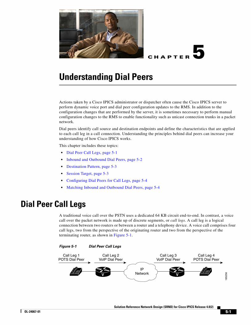
Solution Reference NeOL-24067-01
C H A P T E R 5
Understanding Dial PeersActions taken by a Cisco IPICS administrator or dispatcher often cause the Cisco IPICS server to perform dynamic voice port and dial peer configuration updates to the RMS. In addition to the configuration changes that are performed by the server, it is sometimes necessary to perform manual configuration changes to the RMS to enable functionality such as unicast connection trunks in a packet network.
Dial peers identify call source and destination endpoints and define the characteristics that are applied to each call leg in a call connection. Understanding the principles behind dial peers can increase your understanding of how Cisco IPICS works.
This chapter includes these topics:
• Dial Peer Call Legs, page 5-1
• Inbound and Outbound Dial Peers, page 5-2
• Destination Pattern, page 5-3
• Session Target, page 5-3
• Configuring Dial Peers for Call Legs, page 5-4
• Matching Inbound and Outbound Dial Peers, page 5-4
Dial Peer Call LegsA traditional voice call over the PSTN uses a dedicated 64 KB circuit end-to-end. In contrast, a voice call over the packet network is made up of discrete segments, or call legs. A call leg is a logical connection between two routers or between a router and a telephony device. A voice call comprises four call legs, two from the perspective of the originating router and two from the perspective of the terminating router, as shown in Figure 5-1.
Figure 5-1 Dial Peer Call Legs
1852
56
IPNetwork
Call Leg 1POTS Dial Peer
Call Leg 4POTS Dial Peer
Call Leg 2VoIP Dial Peer
Call Leg 3VoIP Dial Peer
V V
5-1twork Design (SRND) for Cisco IPICS Release 4.0(2)
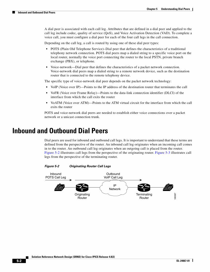
Chapter 5 Understanding Dial PeersInbound and Outbound Dial Peers
A dial peer is associated with each call leg. Attributes that are defined in a dial peer and applied to the call leg include codec, quality of service (QoS), and Voice Activation Detection (VAD). To complete a voice call, you must configure a dial peer for each of the four call legs in the call connection.
Depending on the call leg, a call is routed by using one of these dial peer types:
• POTS (Plain Old Telephone Service)–Dial peer that defines the characteristics of a traditional telephony network connection. POTS dial peers map a dialed string to a specific voice port on the local router, normally the voice port connecting the router to the local PSTN, private branch exchange (PBX), or telephone.
• Voice-network—Dial peer that defines the characteristics of a packet network connection. Voice-network dial peers map a dialed string to a remote network device, such as the destination router that is connected to the remote telephony device.
The specific type of voice-network dial peer depends on the packet network technology:
• VoIP (Voice over IP)—Points to the IP address of the destination router that terminates the call
• VoFR (Voice over Frame Relay)—Points to the data-link connection identifier (DLCI) of the interface from which the call exits the router
• VoATM (Voice over ATM)—Points to the ATM virtual circuit for the interface from which the call exits the router
POTS and voice-network dial peers are needed to establish either voice connections over a packet network or a unicast connection trunk.
Inbound and Outbound Dial Peers Dial peers are used for inbound and outbound call legs. It is important to understand that these terms are defined from the perspective of the router. An inbound call leg originates when an incoming call comes in to the router. An outbound call leg originates when an outgoing call is placed from the router. Figure 5-2 illustrates call legs from the perspective of the originating router. Figure 5-3 illustrates call legs from the perspective of the terminating router.
Figure 5-2 Originating Router Call Legs
1805
87
IPNetwork
InboundPOTS Call Leg
OutboundVoIP Call Leg
V VOriginating
RouterTerminating
Router
5-2Solution Reference Network Design (SRND) for Cisco IPICS Release 4.0(2)
OL-24067-01
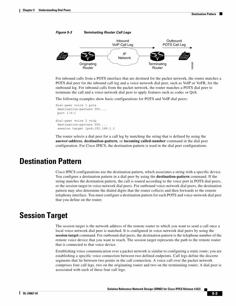
Chapter 5 Understanding Dial PeersDestination Pattern
Figure 5-3 Terminating Router Call Legs
For inbound calls from a POTS interface that are destined for the packet network, the router matches a POTS dial peer for the inbound call leg and a voice-network dial peer, such as VoIP or VoFR, for the outbound leg. For inbound calls from the packet network, the router matches a POTS dial peer to terminate the call and a voice-network dial peer to apply features such as codec or QoS.
The following examples show basic configurations for POTS and VoIP dial peers:
dial-peer voice 1 pots destination-pattern 555.... port 1/0:1
dial-peer voice 2 voip destination-pattern 555.... session target ipv4:192.168.1.1
The router selects a dial peer for a call leg by matching the string that is defined by using the answer-address, destination-pattern, or incoming called-number command in the dial peer configuration. For Cisco IPICS, the destination-pattern is used in the dial peer configurations.
Destination Pattern Cisco IPICS configurations use the destination pattern, which associates a string with a specific device. You configure a destination pattern in a dial peer by using the destination-pattern command. If the string matches the destination pattern, the call is routed according to the voice port in POTS dial peers, or the session target in voice-network dial peers. For outbound voice-network dial peers, the destination pattern may also determine the dialed digits that the router collects and then forwards to the remote telephony interface. You must configure a destination pattern for each POTS and voice-network dial peer that you define on the router.
Session Target The session target is the network address of the remote router to which you want to send a call once a local voice-network dial peer is matched. It is configured in voice-network dial peers by using the session target command. For outbound dial peers, the destination pattern is the telephone number of the remote voice device that you want to reach. The session target represents the path to the remote router that is connected to that voice device.
Establishing voice communication over a packet network is similar to configuring a static route; you are establishing a specific voice connection between two defined endpoints. Call legs define the discrete segments that lie between two points in the call connection. A voice call over the packet network comprises four call legs, two on the originating router and two on the terminating router. A dial peer is associated with each of these four call legs.
1805
88
IPNetwork
OutboundPOTS Call Leg
InboundVoIP Call Leg
V VOriginating
RouterTerminating
Router
5-3Solution Reference Network Design (SRND) for Cisco IPICS Release 4.0(2)
OL-24067-01
Chapter 5 Understanding Dial PeersConfiguring Dial Peers for Call Legs
Configuring Dial Peers for Call Legs When a voice call comes into the router, the router must match dial peers to route the call. For inbound calls from a POTS interface that are being sent over the packet network, the router matches a POTS dial peer for the inbound call leg and a voice-network dial peer for the outbound call leg. For calls coming into the router from the packet network, the router matches an outbound POTS dial peer to terminate the call and an inbound voice-network dial peer for features such as codec, VAD, and QoS.
Matching Inbound and Outbound Dial Peers To match inbound call legs to dial peers, the router uses three information elements in the call setup message and four configurable dial peer attributes. The call setup elements are:
• Called number or dialed number identification service (DNIS)—Set of numbers representing the destination
• Calling number or automatic number identification (ANI)—Set of numbers representing the origin
• Voice port—Voice port carrying the call.
The configurable dial peer attributes are:
• Incoming called-number—String representing the called number or DNIS. It is configured by using the incoming called-number dial-peer configuration command in POTS and VoIP dial peers.
• Answer address—String representing the calling number or ANI. It is configured by using the answer-address dial-peer configuration command in POTS or VoIP dial peers and is used only for inbound calls from the IP network.
• Destination pattern-—String representing the calling number or ANI. It is configured by using the destination-pattern dial-peer configuration command in POTS or voice-network dial peers.
• Port—Voice port through which calls to this dial peer are placed.
The router selects an inbound dial peer by matching the information elements in the setup message with the dial peer attributes. The router attempts to match these items in the following order:
1. Called number with incoming called-number.
2. Calling number with answer-address.
3. Calling number with destination-pattern.
4. Incoming voice port with configured voice port.
The router must match only one of these conditions to select a dial peer. It is not necessary for all the attributes to be configured in the dial peer or that every attribute match the call setup information. The router stops searching as soon as one dial peer is matched and the call is routed according to the configured dial peer attributes. Even if there are other dial peers that would match, only the first match is used.
The router selects an outbound dial peer based on the dial string. If the dial string matches a configured dial peer, the router places the call by using the configured attributes in the matching dial peer.
5-4Solution Reference Network Design (SRND) for Cisco IPICS Release 4.0(2)
OL-24067-01

Solution Reference NeOL-24067-01
C H A P T E R 6
Cisco IPICS Licensing and Sizing GuidelinesThis chapter provides information about how Cisco IPICS uses licensable features. It also provides information about resource usage and system sizing. Use this information to help plan your Cisco IPICS deployment.
This chapter includes these topics:
• Resource and License Usage, page 6-1
• DS0 Usage, page 6-1
• Additional Planning and Sizing Guidelines, page 6-1
• Dial Port Licensing Details, page 6-3
Resource and License UsageTo properly design a Cisco IPICS deployment, it is important to understand how resources are licensed and used. The Cisco IPICS license determines the number of concurrent land mobile radio (LMR) ports, multicast ports, IDC users, IP phone users, dial users, and ops views that are available for your system. The total number of LMR and multicast ports, IDC, IP phone, dial users, and ops views cannot exceed the number that is specified in the license or licenses that you purchased. Refer to the “Managing Licenses” section in Cisco IPICS Server Administration Guide, Release 4.0(2).
DS0 UsageA single DS0 loopback pair is used in the following situations:
• For each remote channel on and IDC
• For each channel in an active VTG
• For each instance of an active VTG that is accessed by a dial-in or dial-out user, regardless of the number of users who are connected to the VTG
Additional Planning and Sizing GuidelinesTo estimate the number of T1 DS0 loopback circuits that are required for the RMS components in a Cisco IPICS deployment, consider the following guidelines:
6-1twork Design (SRND) for Cisco IPICS Release 4.0(2)
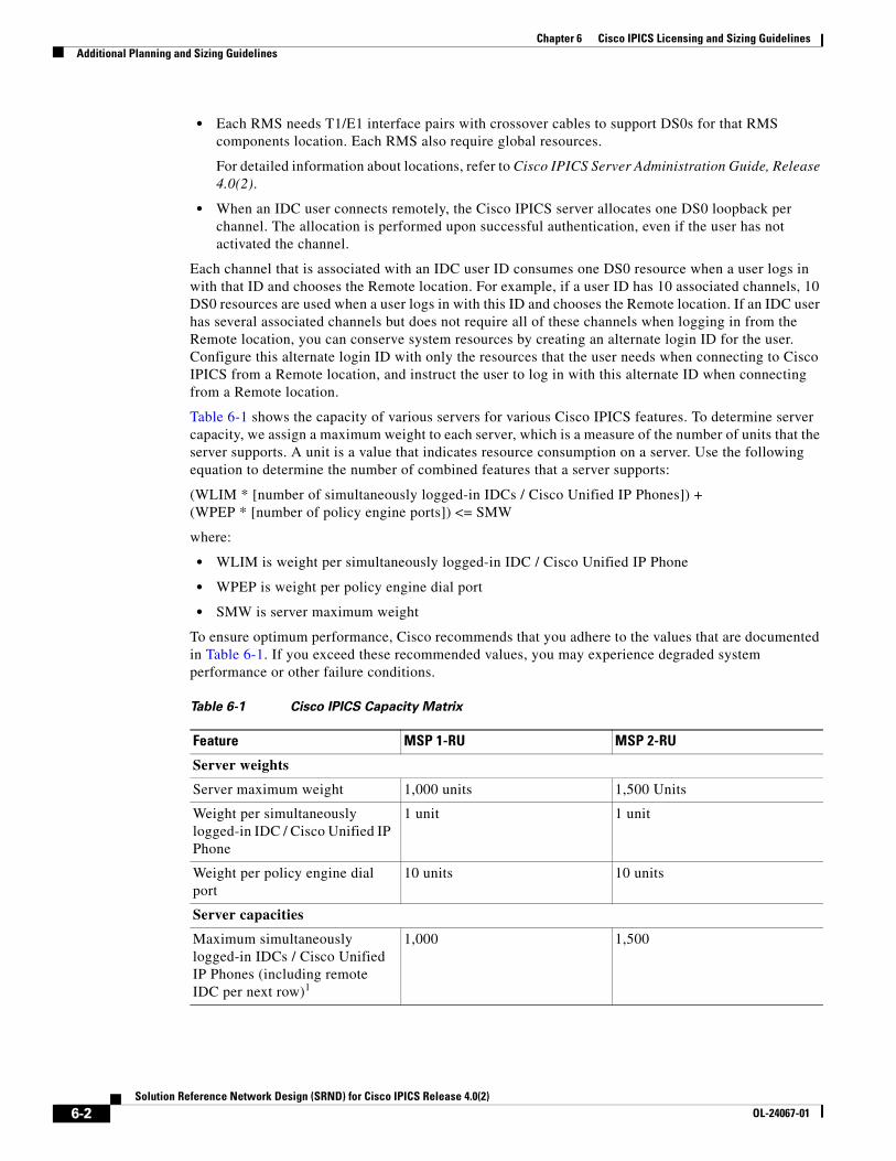
Chapter 6 Cisco IPICS Licensing and Sizing GuidelinesAdditional Planning and Sizing Guidelines
• Each RMS needs T1/E1 interface pairs with crossover cables to support DS0s for that RMS components location. Each RMS also require global resources.
For detailed information about locations, refer to Cisco IPICS Server Administration Guide, Release 4.0(2).
• When an IDC user connects remotely, the Cisco IPICS server allocates one DS0 loopback per channel. The allocation is performed upon successful authentication, even if the user has not activated the channel.
Each channel that is associated with an IDC user ID consumes one DS0 resource when a user logs in with that ID and chooses the Remote location. For example, if a user ID has 10 associated channels, 10 DS0 resources are used when a user logs in with this ID and chooses the Remote location. If an IDC user has several associated channels but does not require all of these channels when logging in from the Remote location, you can conserve system resources by creating an alternate login ID for the user. Configure this alternate login ID with only the resources that the user needs when connecting to Cisco IPICS from a Remote location, and instruct the user to log in with this alternate ID when connecting from a Remote location.
Table 6-1 shows the capacity of various servers for various Cisco IPICS features. To determine server capacity, we assign a maximum weight to each server, which is a measure of the number of units that the server supports. A unit is a value that indicates resource consumption on a server. Use the following equation to determine the number of combined features that a server supports:
(WLIM * [number of simultaneously logged-in IDCs / Cisco Unified IP Phones]) + (WPEP * [number of policy engine ports]) <= SMW
where:
• WLIM is weight per simultaneously logged-in IDC / Cisco Unified IP Phone
• WPEP is weight per policy engine dial port
• SMW is server maximum weight
To ensure optimum performance, Cisco recommends that you adhere to the values that are documented in Table 6-1. If you exceed these recommended values, you may experience degraded system performance or other failure conditions.
Table 6-1 Cisco IPICS Capacity Matrix
Feature MSP 1-RU MSP 2-RU
Server weights
Server maximum weight 1,000 units 1,500 Units
Weight per simultaneously logged-in IDC / Cisco Unified IP Phone
1 unit 1 unit
Weight per policy engine dial port
10 units 10 units
Server capacities
Maximum simultaneously logged-in IDCs / Cisco Unified IP Phones (including remote IDC per next row)1
1,000 1,500
6-2Solution Reference Network Design (SRND) for Cisco IPICS Release 4.0(2)
OL-24067-01
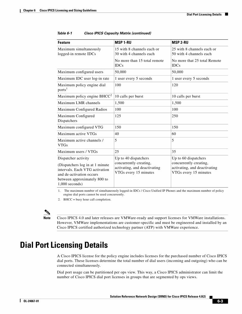
Chapter 6 Cisco IPICS Licensing and Sizing GuidelinesDial Port Licensing Details
Note Cisco IPICS 4.0 and later releases are VMWare-ready and support licenses for VMWare installations. However, VMWare implementations are customer-specific and must be engineered and installed by an Cisco IPICS certified authorized technology partner (ATP) with VMWare experience.
Dial Port Licensing DetailsA Cisco IPICS license for the policy engine includes licenses for the purchased number of Cisco IPICS dial ports. These licenses determine the total number of dial users (incoming and outgoing) who can be connected simultaneously.
Dial port usage can be partitioned per ops view. This way, a Cisco IPICS administrator can limit the number of Cisco IPICS dial port licenses in groups that are segmented by ops views.
Maximum simultaneously logged-in remote IDCs
15 with 8 channels each or 30 with 4 channels each
No more than 15 total remote IDCs
25 with 8 channels each or 50 with 4 channels each
No more that 25 total Remote IDCs
Maximum configured users 50,000 50,000
Maximum IDC user log-in rate 1 user every 5 seconds 1 user every 5 seconds
Maximum policy engine dial ports1
100 120
Maximum policy engine BHCC2 10 calls per burst 10 calls per burst
Maximum LMR channels 1,500 1,500
Maximum Configured Radios 100 100
Maximum Configured Dispatchers
125 250
Maximum configured VTG 150 150
Maximum active VTGs 40 60
Maximum active channels / VTGs
5 5
Maximum users / VTGs 25 35
Dispatcher activity
(Dispatchers log in at 1 minute intervals. Each VTG activation and de-activation occurs between approximately 800 to 1,000 seconds)
Up to 40 dispatchers concurrently creating, activating, and deactivating VTGs every 15 minutes
Up to 60 dispatchers concurrently creating, activating, and deactivating VTGs every 15 minutes
1. The maximum number of simultaneously logged-in IDCs / Cisco Unified IP Phones and the maximum number of policy engine dial ports cannot be used concurrently.
2. BHCC = busy hour call completion.
Table 6-1 Cisco IPICS Capacity Matrix (continued)
Feature MSP 1-RU MSP 2-RU
6-3Solution Reference Network Design (SRND) for Cisco IPICS Release 4.0(2)
OL-24067-01

Chapter 6 Cisco IPICS Licensing and Sizing GuidelinesDial Port Licensing Details
Dial ports from the available dial pool are used by the currently executing policy notification or invite actions. If there are fewer dial ports available than what is needed, other policy actions will wait for a dial port to become available.
The recipient of a call must authenticate properly for the call to succeed. Otherwise, the call is considered unsuccessful and the system moves on to the next number that is configured in the dial preferences for the recipient. If you want the system to retry the same number, enter the same number again as a dial preference. The system attempts one call to each number in the dial preferences. It stops attempting calls when the recipient authenticates properly or when the system has tried all numbers.
Dial pool configurations are made in the Administration Console Ops View window. For detailed information, refer to the “Configuring and Managing Cisco IPICS Operational Views” chapter in Cisco IPICS Server Administration Guide, Release 4.0(2).
6-4Solution Reference Network Design (SRND) for Cisco IPICS Release 4.0(2)
OL-24067-01
Solution Reference NeOL-24067-01
C H A P T E R 7
Cisco IPICS Deployment ModelsThis chapter describes Cisco IPICS deployment models. You can use these models as guides when you design your Cisco IPICS deployment.
This chapter includes these topics:
• Single Site Model, page 7-1
• Multiple Site Model, page 7-2
Single Site ModelThe Cisco IPICS single site model represents a deployment in a single multicast domain. Cisco IPICS components are located at one multicast-enabled site or campus, with no Cisco IPICS multicast services provided over an IP WAN. The single site model typically is deployed over a LAN or metropolitan area network (MAN), either of which carries the multicast voice traffic within the site. Calls from beyond the LAN or MAN use the Cisco IPICS Remote capability to connect to the Cisco IPICS domain via a SIP-based unicast call.
The single site model has the following design characteristics:
• Cisco IPICS server
• RMS
• IDCs
• Cisco Unified IP Phones
• LMR gateways (optional)
• Multicast-enabled network using PIM Sparse mode.
• RMS digital signal processor (DSP) resources for conferencing and transcoding
Figure 7-1 illustrates the Cisco IPICS single site model.
7-1twork Design (SRND) for Cisco IPICS Release 4.0(2)
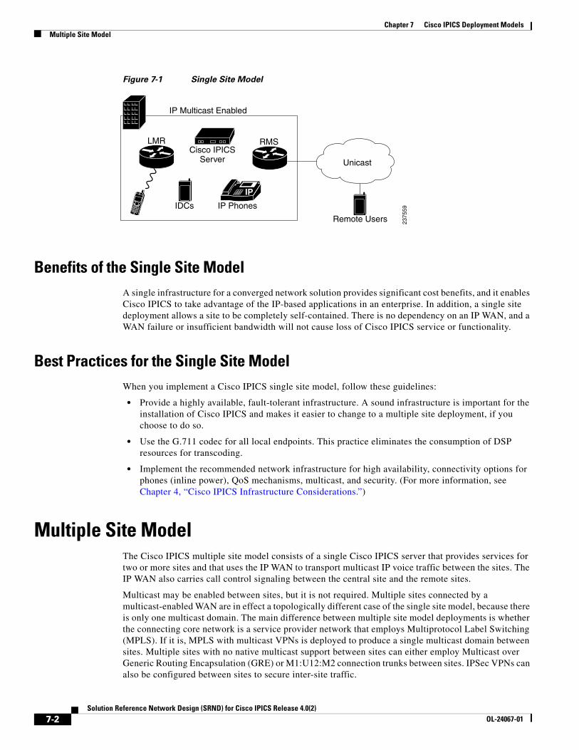
Chapter 7 Cisco IPICS Deployment ModelsMultiple Site Model
Figure 7-1 Single Site Model
Benefits of the Single Site Model A single infrastructure for a converged network solution provides significant cost benefits, and it enables Cisco IPICS to take advantage of the IP-based applications in an enterprise. In addition, a single site deployment allows a site to be completely self-contained. There is no dependency on an IP WAN, and a WAN failure or insufficient bandwidth will not cause loss of Cisco IPICS service or functionality.
Best Practices for the Single Site Model When you implement a Cisco IPICS single site model, follow these guidelines:
• Provide a highly available, fault-tolerant infrastructure. A sound infrastructure is important for the installation of Cisco IPICS and makes it easier to change to a multiple site deployment, if you choose to do so.
• Use the G.711 codec for all local endpoints. This practice eliminates the consumption of DSP resources for transcoding.
• Implement the recommended network infrastructure for high availability, connectivity options for phones (inline power), QoS mechanisms, multicast, and security. (For more information, see Chapter 4, “Cisco IPICS Infrastructure Considerations.”)
Multiple Site ModelThe Cisco IPICS multiple site model consists of a single Cisco IPICS server that provides services for two or more sites and that uses the IP WAN to transport multicast IP voice traffic between the sites. The IP WAN also carries call control signaling between the central site and the remote sites.
Multicast may be enabled between sites, but it is not required. Multiple sites connected by a multicast-enabled WAN are in effect a topologically different case of the single site model, because there is only one multicast domain. The main difference between multiple site model deployments is whether the connecting core network is a service provider network that employs Multiprotocol Label Switching (MPLS). If it is, MPLS with multicast VPNs is deployed to produce a single multicast domain between sites. Multiple sites with no native multicast support between sites can either employ Multicast over Generic Routing Encapsulation (GRE) or M1:U12:M2 connection trunks between sites. IPSec VPNs can also be configured between sites to secure inter-site traffic.
IP
Cisco IPICSServer
IDCs IP Phones
LMR RMS
IP Multicast Enabled
Unicast
Remote Users 2375
59
7-2Solution Reference Network Design (SRND) for Cisco IPICS Release 4.0(2)
OL-24067-01
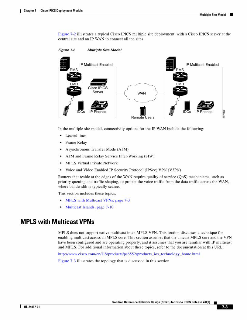
Chapter 7 Cisco IPICS Deployment ModelsMultiple Site Model
Figure 7-2 illustrates a typical Cisco IPICS multiple site deployment, with a Cisco IPICS server at the central site and an IP WAN to connect all the sites.
Figure 7-2 Multiple Site Model
In the multiple site model, connectivity options for the IP WAN include the following:
• Leased lines
• Frame Relay
• Asynchronous Transfer Mode (ATM)
• ATM and Frame Relay Service Inter-Working (SIW)
• MPLS Virtual Private Network
• Voice and Video Enabled IP Security Protocol (IPSec) VPN (V3PN)
Routers that reside at the edges of the WAN require quality of service (QoS) mechanisms, such as priority queuing and traffic shaping, to protect the voice traffic from the data traffic across the WAN, where bandwidth is typically scarce.
This section includes these topics:
• MPLS with Multicast VPNs, page 7-3
• Multicast Islands, page 7-10
MPLS with Multicast VPNsMPLS does not support native multicast in an MPLS VPN. This section discusses a technique for enabling multicast across an MPLS core. This section assumes that the unicast MPLS core and the VPN have been configured and are operating properly, and it assumes that you are familiar with IP multicast and MPLS. For additional information about these topics, refer to the documentation at this URL:
http://www.cisco.com/en/US/products/ps6552/products_ios_technology_home.html
Figure 7-3 illustrates the topology that is discussed in this section.
IP
Cisco IPICSServer
IDCs IP Phones
LMR
RMS IP Multicast Enabled
Remote Users
IP
IDCs IP Phones
LMR
RMS IP Multicast Enabled
2375
60
WAN
7-3Solution Reference Network Design (SRND) for Cisco IPICS Release 4.0(2)
OL-24067-01
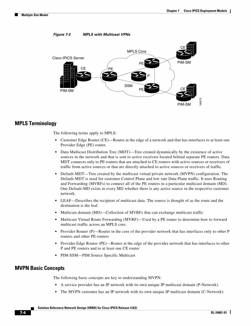
Chapter 7 Cisco IPICS Deployment ModelsMultiple Site Model
Figure 7-3 MPLS with Multicast VPNs
MPLS Terminology
The following terms apply to MPLS:
• Customer Edge Router (CE)—Router at the edge of a network and that has interfaces to at least one Provider Edge (PE) router.
• Data Multicast Distribution Tree (MDT)—Tree created dynamically by the existence of active sources in the network and that is sent to active receivers located behind separate PE routers. Data MDT connects only to PE routers that are attached to CE routers with active sources or receivers of traffic from active sources or that are directly attached to active sources or receivers of traffic.
• Default-MDT—Tree created by the multicast virtual private network (MVPN) configuration. The Default-MDT is used for customer Control Plane and low rate Data Plane traffic. It uses Routing and Forwarding (MVRFs) to connect all of the PE routers in a particular multicast domain (MD). One Default-MD exists in every MD whether there is any active source in the respective customer network.
• LEAF—Describes the recipient of multicast data. The source is thought of as the route and the destination is the leaf.
• Multicast domain (MD)—Collection of MVRFs that can exchange multicast traffic
• Multicast Virtual Route Forwarding (MVRF)—Used by a PE router to determine how to forward multicast traffic across an MPLS core.
• Provider Router (P)—Router in the core of the provider network that has interfaces only to other P routers and other PE routers
• Provider Edge Router (PE)—Router at the edge of the provider network that has interfaces to other P and PE routers and to at least one CE router
• PIM-SSM—PIM Source Specific Multicast
MVPN Basic Concepts
The following basic concepts are key to understanding MVPN:
• A service provider has an IP network with its own unique IP multicast domain (P-Network).
• The MVPN customer has an IP network with its own unique IP multicast domain (C-Network).
Cisco IPICS Server
CE
CE
CEPIM-SM
PIM-SM
PIM-SM
PE
PE
PE
P
SSM
MPLS Core
1805
75
7-4Solution Reference Network Design (SRND) for Cisco IPICS Release 4.0(2)
OL-24067-01
Chapter 7 Cisco IPICS Deployment ModelsMultiple Site Model
• The Service Provider MVPN network forwards the customer IP multicast data to remote customer sites. To do so, the service provider encapsulates customer traffic (C-packets) inside P- packets at the service provider PE. The encapsulated P-packet is then forwarded to remote PE sites as native multicast inside the P-Network
• During the process of forwarding encapsulated P-packets, the P-Network has no knowledge of the C-Network traffic. The PE is the device that participates in both networks. (There may be more than one Customer Network per PE.)
VPN Multicast Routing
A PE router in an MVPN network has several routing tables. There is one global unicast/multicast routing table and a unicast/multicast routing table for each directly connected MVRF.
Multicast domains are based on the principle of encapsulating multicast packets from a VPN in multicast packets to be routed in the core. As multicast is used in the core network, PIM must be configured in the core. PIM-SM, PIM-SSM, and PIM-BIDIR are supported inside the provider core for MVPN. PIM-SM or PIM-SSM is the recommended PIM option in the provider core, because PIM-BIDIR is not supported on all platforms. PIM-SM, PIM-SSM, PIM-BIDIR and PIM-DENSE-MODE are supported inside the MVPN. MVPN leverages Multicast Distribution Trees (MDTs). An MDT is sourced by a PE router and has a multicast destination address. PE routers that have sites for the same MVPN source to a default MDT and join to receive traffic on it.
In addition, a Default-MDT is a tree that is always-on and that transports PIM control-traffic, dense-mode traffic, and rp-tree (*,G) traffic. All PE routers configured with the same default-MDT receive this traffic.
Data MDTs are trees that are created on demand and that will only be joined by the PE routers that have interested receivers for the traffic. Data MDTs can be created either by a traffic rate threshold or a source-group pair. Default-MDTs must have the same group address for all VPN Routing and Forwarding (VRFs) that make up a MVPN. Data MDTs may have the same group address if PIM-SSM is used. If PIM-SM is used, they must have a different group address, because providing the same one could result in the PE router receiving unwanted traffic.
Configuring the Provider Network for MVPN
This section provides an example of how to configure a provider network for MVPN.
The steps required to enable a MVPN in the provider network refer to the topology illustrated in Figure 7-3 on page 7-4. In these steps, the customer VPN is called “ipics.”
Procedure
Step 1 Choose the PIM mode for the provider network.
Cisco recommends PIM-SSM as the protocol in the core. No additional source-discovery BGP configuration is required with the source-discovery attribute. A route distinguisher (RD) type is used to advertise the source of the MDT with the MDT group address. PIM-SM has been the most widely deployed multicast protocol and has been used for both sparsely and densely populated application requirements. PIM SSM is based upon PIM SM. Without the initial Shared Tree and the subsequent cutover to the Shortest Path Tree, either PIM SSM or PIM SM is suitable for the default MDT.
7-5Solution Reference Network Design (SRND) for Cisco IPICS Release 4.0(2)
OL-24067-01
Chapter 7 Cisco IPICS Deployment ModelsMultiple Site Model
When bidirectional PIM support becomes available on all relevant hardware, it will be the recommendation for the default MDT. For the Data MDT, either PIM SM or PIM SSM is suitable. PIM SSM is simpler to deploy than PIM SM. It does not require a Rendezvous point, and the Provider network is a known and stable group of multicast devices. Cisco recommends the use of PIM SSM for Provider core deployment. This configuration example uses PIM-SSM in the core.
Step 2 Choose the VPN group addresses used inside the provider network:
The default PIM-SSM range is 232/8. However, this address range is designed for global use in the Internet. For use within a private domain, you should use an address outside of this administratively scoped multicast range (as recommended in RFC2365). Using a private address range makes it simpler to filter on boundary routers. Cisco recommends using 239.232/16, because addresses in this range are easily recognizable as both private addresses and SSM addresses by using 232 in the second octet. In the design discussed in this document, the range is divided for default-MDT and data MDT. (Data MDT is discussed elsewhere in the “VPN Multicast Routing” section on page 7-5. Default-MDTs uses 239.232.0.0-239.232.0.255 and Data MDTs uses 239.232.1.0-239.232.1.255. This address range provides support for up to 255 MVRFs per PE router.
Step 3 Configure the provider network for PIM-SSM.
The following commands enable a basic PIM-SSM service.
• On all P and PE routers, configure these commands globally:
ip multicast-routingip pim ssm range multicast_ssm_rangeip access-list standard multicast_ssm_range permit 239.232.0.0 0.0.1.255
• On all P interfaces and PE interfaces that face the core, configure this command:
ip pim sparse-mode
• On each PE router, configure this command on the loopback interface that is used to source the BGP session:
ip pim sparse-mode
Step 4 Configure the MDT on the VRF.
• To configure multicast routing on the VRF, configure these commands on all PE routers for the VRF ipics:
ip vrf ipicsmdt default 239.232.0.0
• To enable multicast routing for the VRF, configure this command:
ip multicast-routing vrf ipics
Step 5 Configure the PIM mode inside the VPN.
The PIM mode inside the VPN depends on what type of PIM the VPN customer is using. Cisco provides automatic discovery of the group-mode used inside the VPN via auto-rp or bootstrap router (BSR), which requires no additional configuration. Optionally, a provider may choose to provide the RP for the customer by configuring the PE router as an RP inside the VPN. In the topology discussed in this section, the VPN customer provides the RP service and the PE routers will automatically learn the group-to-rendezvous point (RP) via auto-rp.
7-6Solution Reference Network Design (SRND) for Cisco IPICS Release 4.0(2)
OL-24067-01
Chapter 7 Cisco IPICS Deployment ModelsMultiple Site Model
Configure all PE-CE interfaces for sparse-dense-mode, which ensures that either auto-rp or BSR messages are received and forwarded, and which allows the PE to learn the group-to-rendezvous point (RP) inside the VPN. To do so, configure the following on all customer facing interfaces:
ip pim sparse-mode
Verifying the Provider Network for MVPN
After you complete the configuration as described in the “Configuring the Provider Network for MVPN” section on page 7-5, use the following procedure to verify that the configuration is correct:
Procedure
Step 1 Verify BGP updates.
BGP provides for source discovery when SSM is used, which is known as a BGP-MDT update. to verify that all BGP-MDT updates have been received correctly on the PE routers, take either of these actions:
• Use the show ip pim mdt bgp command:
PE1#show ip pim mdt bgpPeer (Route Distinguisher + IPv4) Next Hop MDT group 239.232.0.0 2:65019:1:10.32.73.248 10.32.73.248 (PE-2 Loopback) 2:65019:1:10.32.73.250 10.32.73.250 (PE-3 Loopback)
2:65019:1 indicates the RD-type (2) and RD (65019:1) that is associated with this update.
The remaining output is the address that is used to source the BGP session.
• Use the show ip bgp vpnv4 all command:
PE1#show ip bgp vpnv4 allBGP table version is 204, local router ID is 10.32.73.247Status codes: s suppressed, d damped, h history, * valid, > best, i - internal, r RIB-failure, S StaleOrigin codes: i - IGP, e - EGP, ? - incomplete
Network Next Hop Metric LocPrf Weight PathRoute Distinguisher: 65019:1 (default for vrf ipics)*>i10.32.72.48/28 10.32.73.248 0 100 0 ?... (output omitted)Route Distinguisher: 2:65019:1*> 10.32.73.247/32 0.0.0.0 0 ?*>i10.32.73.248/32 10.32.73.248 0 100 0 ?*>i10.32.73.250/32 10.32.73.250 0 100 0 ?
Step 2 Verify the global mroute table
Use the show ip mroute mdt-group-address command to verify that there is a (Source, Group) entry for each PE router. Because PIM-SSM is used, the source is the loopback address used to source the BGP session and the Group is the MDT address configured. Without traffic, only default-MDT entries are visible.
PE1#show ip mroute 239.232.0.0IP Multicast Routing TableFlags: D - Dense, S - Sparse, B - Bidir Group, s - SSM Group, C - Connected, L - Local, P - Pruned, R - RP-bit set, F - Register flag, T - SPT-bit set, J - Join SPT, M - MSDP created entry, X - Proxy Join Timer Running, A - Candidate for MSDP Advertisement,
7-7Solution Reference Network Design (SRND) for Cisco IPICS Release 4.0(2)
OL-24067-01

Chapter 7 Cisco IPICS Deployment ModelsMultiple Site Model
U - URD, I - Received Source Specific Host Report, Z - Multicast Tunnel Y - Joined MDT-data group, y - Sending to MDT-data groupOutgoing interface flags: H - Hardware switched Timers: Uptime/Expires Interface state: Interface, Next-Hop or VCD, State/Mode
(10.32.73.247, 239.232.0.0), 1w0d/00:03:26, flags: sTZ Incoming interface: Loopback0, RPF nbr 0.0.0.0 Outgoing interface list: FastEthernet0/0, Forward/Sparse, 1w0d/00:02:47
(10.32.73.248, 239.232.0.0), 1w0d/00:02:56, flags: sTIZ Incoming interface: FastEthernet0/0, RPF nbr 10.32.73.2 Outgoing interface list: MVRF ipics, Forward/Sparse, 1w0d/00:01:30
(10.32.73.250, 239.232.0.0), 1w0d/00:02:55, flags: sTIZ Incoming interface: FastEthernet0/0, RPF nbr 10.32.73.2 Outgoing interface list: MVRF ipics, Forward/Sparse, 1w0d/00:01:29
Verify that the s flag is set on each (S,G) entry, which indicates that this group is used in ssm mode. Verify that the z flag is set, which indicates that this PE router is a leaf of the multicast tunnel. When the router is a leaf of a multicast tunnel, it has to do additional lookups to determine which MVRF to forward this traffic to, as it is basically a receiver for this traffic. Verify the I flag is set for the remote PE(S,G) entry. This flag indicates that the router understands it is joining an SSM group. It is as though an IGMPv3 host had requested to join that particular channel.
Step 3 Verify PIM neighbors in the global table.
Use the show ip pim neighbors command on all PE and P routers to verify that the pim neighbors are setup properly in the global table.
PE1#show ip pim neighborPIM Neighbor TableNeighbor Interface Uptime/Expires Ver DRAddress Prio/Mode10.32.73.2 FastEthernet0/0 1w4d/00:01:21 v2 1 / DR10.32.73.70 Serial0/2 1w4d/00:01:29 v2 1 / S
Step 4 Verify PIM neighbors inside the VPN
Use the show ip pim vrf ipics neighbors command on all PE routers to verify that the CE router is seen as a PIM neighbor and that the remote-PE routers are seen as pim neighbors over the tunnel.
PE1#show ip pim vrf ipics neighborPIM Neighbor TableNeighbor Interface Uptime/Expires Ver DRAddress Prio/Mode10.32.73.66 Serial0/0 1w3d/00:01:18 v2 1 / S10.32.73.248 Tunnel0 3d17h/00:01:43 v2 1 / S10.32.73.250 Tunnel0 1w0d/00:01:42 v2 1 / DR S
Step 5 Verify the VPN group-to-rendezvous point (RP).
The main customer site has been configured to use auto-rp within the VPN. VPN IPICS is using the multicast range 239.192.21.64 - 79 for channels and VTGs.
ip pim send-rp-announce Loopback0 scope 16 group-list multicast_rangeip pim send-rp-discovery scope 16ip access-list standard multicast_range permit 239.192.21.64 0.0.0.15
7-8Solution Reference Network Design (SRND) for Cisco IPICS Release 4.0(2)
OL-24067-01
Chapter 7 Cisco IPICS Deployment ModelsMultiple Site Model
Use the show ip pim vrf ipics rp mapping command to verify that the PE router correctly learned the RP mapping information from the VPN.
PE1#show ip pim vrf ipics rp mapPIM Group-to-RP Mappings
Group(s) 239.192.21.64/28 RP 10.32.72.248 (?), v2v1 Info source: 10.32.73.62 (?), elected via Auto-RP Uptime: 1w3d, expires: 00:02:54
This output shows that the PE router has correctly learned the group-to-rendezvous point (RP), which is used inside the VPN. The default-MDT reaches all PE routers in the core of the provide network in which the multicast replication is performed. With only a default-MDT configured, traffic goes to all PE routers, regardless of whether they want to receive the traffic.
Optimizing Traffic Forwarding: Data MDT
Data MDT is designed to optimize traffic forwarding. Data MDT is a multicast tree that is constructed on demand. The conditions to create a data MDT are based upon traffic-load threshold measured in kbps or on an access-list that specifies certain sources inside the VPN. A data MDT is created only by the PE that has the source connected to its site. The data MDT conditions do not have to be configured. However, when there are no conditions set for each (S,G) inside the VPN, a data MDT is created. This data MDT requires resources from the router, so it is recommended that you not create one just because a source exists. A non-zero threshold is recommended, because this value requires an active source to trigger the creation of the Data MDT. The maximum number of multi-VPN Routing/Forwarding (MVRF) entries is 256.
To configure the data MDT under the VRF, use one of the ranges that is described in Step 2 in the “Configuring the Provider Network for MVPN” section on page 7-5. A maximum of 256 addresses is allowed per VRF. This limitation is an implementation choice, not a protocol limitation. Because SSM is used, the data MDT address-range may be the same on all PE routers for the same VPN. Use an inverse-mask to specify the number of addresses used for the data MDT, as shown in the following command:
ip vrf ipics mdt data 239.232.1.0 0.0.0.255 threshold 1
Verifying Correct Data MDT Operation
Data MDTs create mroute entries in the global table. There also are specific commands for verifying functionality of the sending and receiving PE router. To verify the data MDT operation, there must be multicast traffic between sites that exceeds the configured threshold. An easy way to test the data MDT is to statically join a multicast group in one site and then ping that group from another site, as shown in the following example:
CE1
interface Loopback0 ip address 10.32.72.248 255.255.255.255 ip pim sparse-mode ip igmp join-group 239.192.21.68
CE2
ping 239.192.21.68 size 500 repeat 100
7-9Solution Reference Network Design (SRND) for Cisco IPICS Release 4.0(2)
OL-24067-01
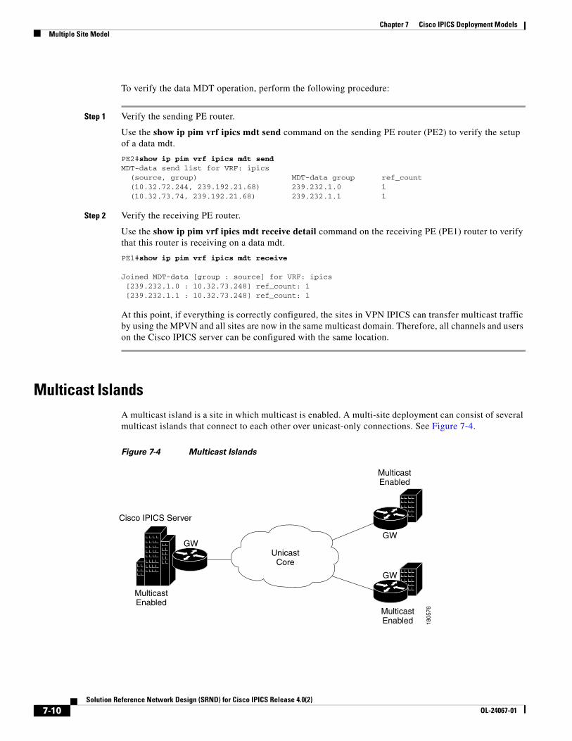
Chapter 7 Cisco IPICS Deployment ModelsMultiple Site Model
To verify the data MDT operation, perform the following procedure:
Step 1 Verify the sending PE router.
Use the show ip pim vrf ipics mdt send command on the sending PE router (PE2) to verify the setup of a data mdt.
PE2#show ip pim vrf ipics mdt sendMDT-data send list for VRF: ipics (source, group) MDT-data group ref_count (10.32.72.244, 239.192.21.68) 239.232.1.0 1 (10.32.73.74, 239.192.21.68) 239.232.1.1 1
Step 2 Verify the receiving PE router.
Use the show ip pim vrf ipics mdt receive detail command on the receiving PE (PE1) router to verify that this router is receiving on a data mdt.
PE1#show ip pim vrf ipics mdt receive
Joined MDT-data [group : source] for VRF: ipics [239.232.1.0 : 10.32.73.248] ref_count: 1 [239.232.1.1 : 10.32.73.248] ref_count: 1
At this point, if everything is correctly configured, the sites in VPN IPICS can transfer multicast traffic by using the MPVN and all sites are now in the same multicast domain. Therefore, all channels and users on the Cisco IPICS server can be configured with the same location.
Multicast IslandsA multicast island is a site in which multicast is enabled. A multi-site deployment can consist of several multicast islands that connect to each other over unicast-only connections. See Figure 7-4.
Figure 7-4 Multicast Islands
Cisco IPICS Server
GWGW
GW
1805
76
MulticastEnabled
MulticastEnabled
MulticastEnabled
UnicastCore
7-10Solution Reference Network Design (SRND) for Cisco IPICS Release 4.0(2)
OL-24067-01
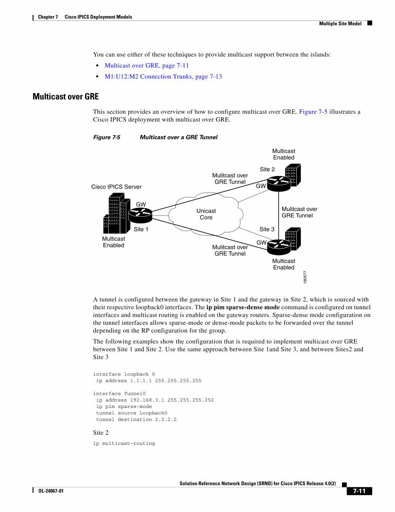
Chapter 7 Cisco IPICS Deployment ModelsMultiple Site Model
You can use either of these techniques to provide multicast support between the islands:
• Multicast over GRE, page 7-11
• M1:U12:M2 Connection Trunks, page 7-13
Multicast over GRE
This section provides an overview of how to configure multicast over GRE. Figure 7-5 illustrates a Cisco IPICS deployment with multicast over GRE.
Figure 7-5 Multicast over a GRE Tunnel
A tunnel is configured between the gateway in Site 1 and the gateway in Site 2, which is sourced with their respective loopback0 interfaces. The ip pim sparse-dense mode command is configured on tunnel interfaces and multicast routing is enabled on the gateway routers. Sparse-dense mode configuration on the tunnel interfaces allows sparse-mode or dense-mode packets to be forwarded over the tunnel depending on the RP configuration for the group.
The following examples show the configuration that is required to implement multicast over GRE between Site 1 and Site 2. Use the same approach between Site 1and Site 3, and between Sites2 and Site 3
interface loopback 0 ip address 1.1.1.1 255.255.255.255
interface Tunnel0 ip address 192.168.3.1 255.255.255.252 ip pim sparse-mode tunnel source Loopback0 tunnel destination 2.2.2.2
Site 2
ip multicast-routing
Cisco IPICS Server GW
GW
GW
1805
77
MulticastEnabled
MulticastEnabled
MulticastEnabled
UnicastCore
Mulitcast overGRE Tunnel
Mulitcast overGRE Tunnel
Mulitcast overGRE Tunnel
Site 1
Site 2
Site 3
7-11Solution Reference Network Design (SRND) for Cisco IPICS Release 4.0(2)
OL-24067-01
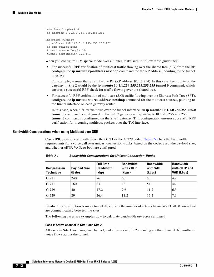
Chapter 7 Cisco IPICS Deployment ModelsMultiple Site Model
interface loopback 0 ip address 2.2.2.2 255.255.255.255
interface Tunnel0 ip address 192.168.3.2 255.255.255.252 ip pim sparse-mode tunnel source Loopback0 tunnel destination 1.1.1.1
When you configure PIM sparse mode over a tunnel, make sure to follow these guidelines:
• For successful RPF verification of multicast traffic flowing over the shared tree (*,G) from the RP, configure the ip mroute rp-address nexthop command for the RP address, pointing to the tunnel interface.
For example, assume that Site 1 has the RP (RP address 10.1.1.254). In this case, the mroute on the gateway in Site 2 would be the ip mroute 10.1.1.254 255.255.255.255 tunnel 0 command, which ensures a successful RPF check for traffic flowing over the shared tree.
• For successful RPF verification of multicast (S,G) traffic flowing over the Shortest Path Tree (SPT), configure the ip mroute source-address nexthop command for the multicast sources, pointing to the tunnel interface on each gateway router.
In this case, when SPT traffic flows over the tunnel interface, an ip mroute 10.1.1.0 255.255.255.0 tunnel 0 command is configured on the Site 2 gateway and ip mroute 10.1.2.0 255.255.255.0 tunnel 0 command is configured on the Site 1 gateway. This configuration ensures successful RPF verification for incoming multicast packets over the Tu0 interface.
Bandwidth Considerations when using Multicast over GRE
Cisco IPICS can operate with either the G.711 or the G.729 codec. Table 7-1 lists the bandwidth requirements for a voice call over unicast connection trunks, based on the codec used, the payload size, and whether cRTP, VAD, or both are configured.
Bandwidth consumption across a tunnel depends on the number of active channels/VTGs/IDC users that are communicating between the sites.
The following cases are examples how to calculate bandwidth use across a tunnel.
Case 1: Active channel in Site 1 and Site 2.
All users in Site 1 are using one channel, and all users in Site 2 are using another channel. No multicast voice flows across the tunnel.
Table 7-1 Bandwidth Considerations for Unicast Connection Trunks
Compression Technique
Payload Size (Bytes)
Full Rate Bandwidth (kbps)
Bandwidth with cRTP (kbps)
Bandwidth with VAD (kbps)
Bandwidth with cRTP and VAD (kbps)
G.711 240 76 66 50 43
G.711 160 83 68 54 44
G.729 40 17.2 9.6 11.2 6.3
G.729 29 26.4 11.2 17.2 7.3
7-12Solution Reference Network Design (SRND) for Cisco IPICS Release 4.0(2)
OL-24067-01
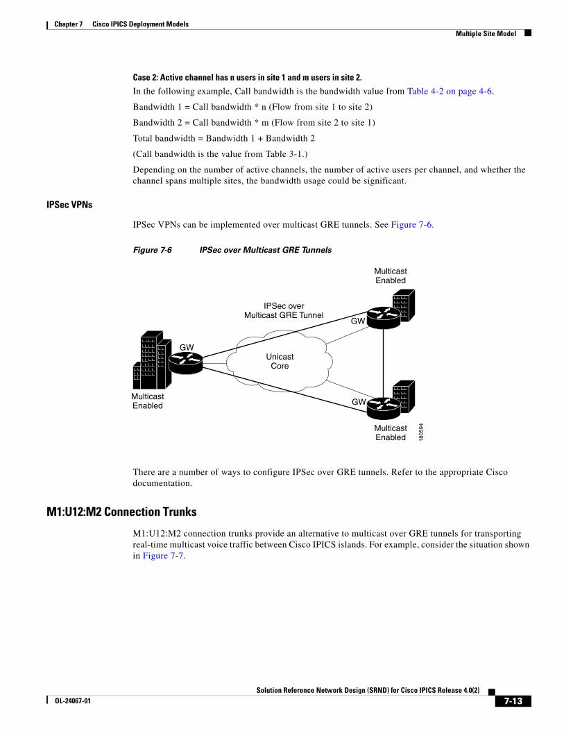
Chapter 7 Cisco IPICS Deployment ModelsMultiple Site Model
Case 2: Active channel has n users in site 1 and m users in site 2.
In the following example, Call bandwidth is the bandwidth value from Table 4-2 on page 4-6.
Bandwidth 1 = Call bandwidth * n (Flow from site 1 to site 2)
Bandwidth 2 = Call bandwidth * m (Flow from site 2 to site 1)
Total bandwidth = Bandwidth 1 + Bandwidth 2
(Call bandwidth is the value from Table 3-1.)
Depending on the number of active channels, the number of active users per channel, and whether the channel spans multiple sites, the bandwidth usage could be significant.
IPSec VPNs
IPSec VPNs can be implemented over multicast GRE tunnels. See Figure 7-6.
Figure 7-6 IPSec over Multicast GRE Tunnels
There are a number of ways to configure IPSec over GRE tunnels. Refer to the appropriate Cisco documentation.
M1:U12:M2 Connection Trunks
M1:U12:M2 connection trunks provide an alternative to multicast over GRE tunnels for transporting real-time multicast voice traffic between Cisco IPICS islands. For example, consider the situation shown in Figure 7-7.
GW
GW
GW
1805
94
MulticastEnabled
MulticastEnabled
MulticastEnabled
UnicastCore
IPSec overMulticast GRE Tunnel
7-13Solution Reference Network Design (SRND) for Cisco IPICS Release 4.0(2)
OL-24067-01
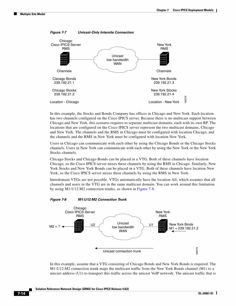
Chapter 7 Cisco IPICS Deployment ModelsMultiple Site Model
Figure 7-7 Unicast-Only Intersite Connection
In this example, the Stocks and Bonds Company has offices in Chicago and New York. Each location has two channels configured on the Cisco IPICS server. Because there is no multicast support between Chicago and New York, this scenario requires to separate multicast domains, each with its own RP. The locations that are configured on the Cisco IPICS server represent the two multicast domains, Chicago and New York. The channels and the RMS in Chicago must be configured with location Chicago, and the channels and the RMS in New York must be configured with location New York.
Users in Chicago can communicate with each other by using the Chicago Bonds or the Chicago Stocks channels. Users in New York can communicate with each other by using the New York or the New York Stocks channels.
Chicago Stocks and Chicago Bonds can be placed in a VTG. Both of these channels have location Chicago, so the Cisco IPICS server mixes these channels by using the RMS in Chicago. Similarly, New York Stocks and New York Bonds can be placed in a VTG. Both of these channels have location New York, so the Cisco IPICS server mixes these channels by using the RMS in New York.
Interdomain VTGs are not possible. VTGs automatically have the location All, which assumes that all channels and users in the VTG are in the same multicast domain. You can work around this limitation by using M1:U12:M2 connection trunks, as shown in Figure 7-8.
Figure 7-8 M1:U12:M2 Connection Trunk
In this example, assume that a VTG consisting of Chicago Bonds and New York Bonds is required. The M1:U12:M2 connection trunk maps the multicast traffic from the New York Bonds channel (M1) to a unicast address (U1) to transport this traffic across the unicast VoIP network. The unicast traffic that is
ChicagoCisco IPICS Server
RMSNew York
RMS
Channels
Ciscago Bonds239.192.21.1
Chicago Stocks239.192.21.2
Location - Chicago
Channels
New York Bonds239.192.21.3
New York Stocks239.192.21.4
Location - New York
Unicastlow bandwidth
WAN
1805
78
ChicagoCisco IPICS Server
RMSNew York
RMS
Unicastlow bandwidth
WAN
1805
79
U2 U1M2 = ?
Unicast connection trunk
New York BindsM1 = 239.192.21.2
7-14Solution Reference Network Design (SRND) for Cisco IPICS Release 4.0(2)
OL-24067-01
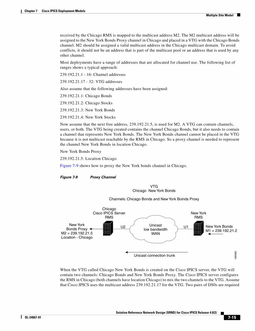
Chapter 7 Cisco IPICS Deployment ModelsMultiple Site Model
received by the Chicago RMS is mapped to the multicast address M2. The M2 multicast address will be assigned to the New York Bonds Proxy channel in Chicago and placed in a VTG with the Chicago Bonds channel. M2 should be assigned a valid multicast address in the Chicago multicast domain. To avoid conflicts, it should not be an address that is part of the multicast pool or an address that is used by any other channel.
Most deployments have a range of addresses that are allocated for channel use. The following list of ranges shows a typical approach:
239.192.21.1 - 16: Channel addresses
239.192.21.17 - 32: VTG addresses
Also assume that the following addresses have been assigned:
239.192.21.1: Chicago Bonds
239.192.21.2: Chicago Stocks
239.192.21.3: New York Bonds
239.192.21.4: New York Stocks
Now assume that the next free address, 239.192.21.5, is used for M2. A VTG can contain channels, users, or both. The VTG being created contains the channel Chicago Bonds, but it also needs to contain a channel that represents New York Bonds. The New York Bonds channel cannot be placed in the VTG because it is not multicast reachable by the RMS in Chicago. So a proxy channel is needed to represent the channel New York Bonds in location Chicago.
New York Bonds Proxy
239.192.21.5: Location Chicago.
Figure 7-9 shows how to proxy the New York bonds channel in Chicago.
Figure 7-9 Proxy Channel
When the VTG called Chicago New York Bonds is created on the Cisco IPICS server, the VTG will contain two channels: Chicago Bonds and New York Bonds Proxy. The Cisco IPICS server configures the RMS in Chicago (both channels have location Chicago) to mix the two channels to the VTG. Assume that Cisco IPICS uses the multicast address 239.192.21.17 for the VTG. Two pairs of DS0s are required
ChicagoCisco IPICS Server
RMSNew York
RMS
Unicastlow bandwidth
WAN18
0580
U2 U1New YorkBonds Proxy
M2 = 239.192.21.5Location - Chicago
Unicast connection trunk
New York BondsM1 = 239.192.21.2
VTGChicago New York Bonds
Channels: Chicago Bonds and New York Boinds Proxy
7-15Solution Reference Network Design (SRND) for Cisco IPICS Release 4.0(2)
OL-24067-01
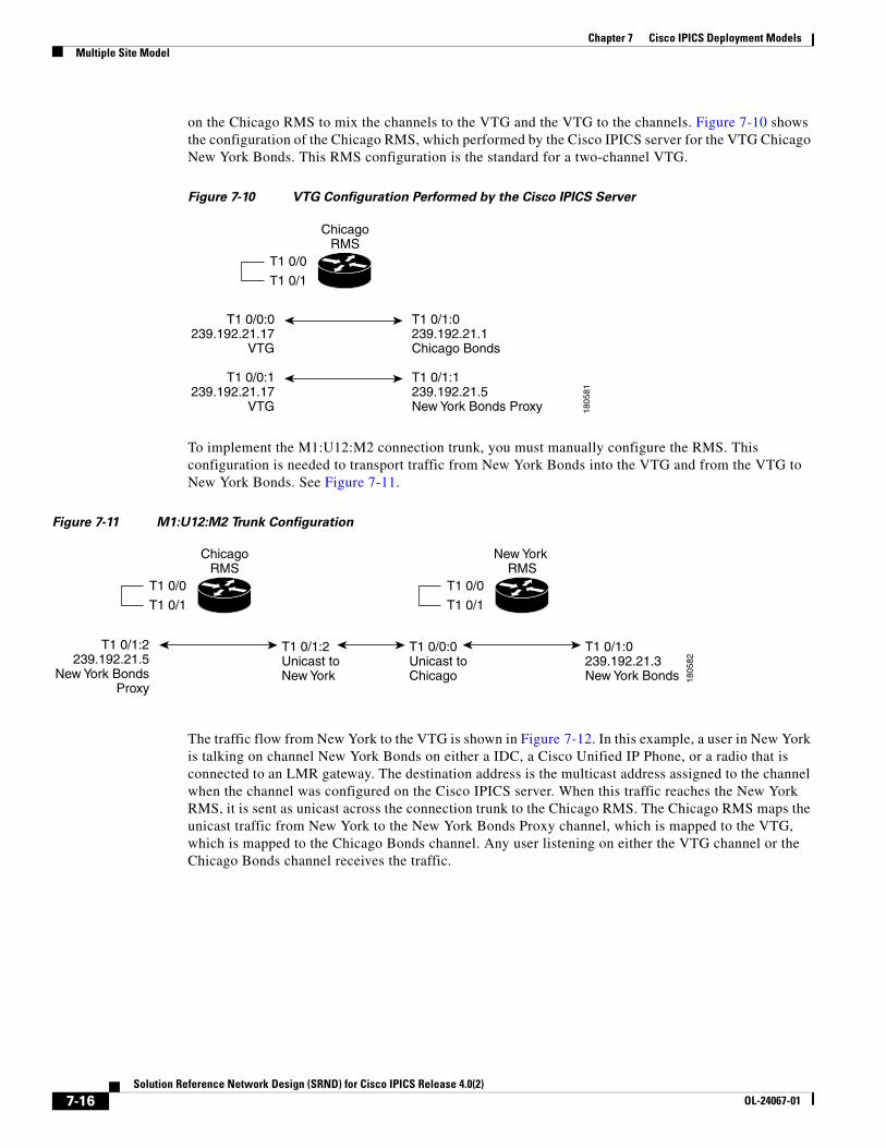
Chapter 7 Cisco IPICS Deployment ModelsMultiple Site Model
on the Chicago RMS to mix the channels to the VTG and the VTG to the channels. Figure 7-10 shows the configuration of the Chicago RMS, which performed by the Cisco IPICS server for the VTG Chicago New York Bonds. This RMS configuration is the standard for a two-channel VTG.
Figure 7-10 VTG Configuration Performed by the Cisco IPICS Server
To implement the M1:U12:M2 connection trunk, you must manually configure the RMS. This configuration is needed to transport traffic from New York Bonds into the VTG and from the VTG to New York Bonds. See Figure 7-11.
Figure 7-11 M1:U12:M2 Trunk Configuration
The traffic flow from New York to the VTG is shown in Figure 7-12. In this example, a user in New York is talking on channel New York Bonds on either a IDC, a Cisco Unified IP Phone, or a radio that is connected to an LMR gateway. The destination address is the multicast address assigned to the channel when the channel was configured on the Cisco IPICS server. When this traffic reaches the New York RMS, it is sent as unicast across the connection trunk to the Chicago RMS. The Chicago RMS maps the unicast traffic from New York to the New York Bonds Proxy channel, which is mapped to the VTG, which is mapped to the Chicago Bonds channel. Any user listening on either the VTG channel or the Chicago Bonds channel receives the traffic.
ChicagoRMS
T1 0/0:0239.192.21.17
VTG
T1 0/1:0239.192.21.1Chicago Bonds
T1 0/0:1239.192.21.17
VTG
T1 0/1:1239.192.21.5New York Bonds Proxy
T1 0/0
T1 0/1
1805
81
ChicagoRMS
T1 0/1:2Unicast toNew York
T1 0/0:0Unicast toChicago
T1 0/1:0239.192.21.3New York Bonds
T1 0/1:2239.192.21.5
New York BondsProxy
T1 0/0
T1 0/1
New York RMS
T1 0/0
T1 0/1
1805
82
7-16Solution Reference Network Design (SRND) for Cisco IPICS Release 4.0(2)
OL-24067-01
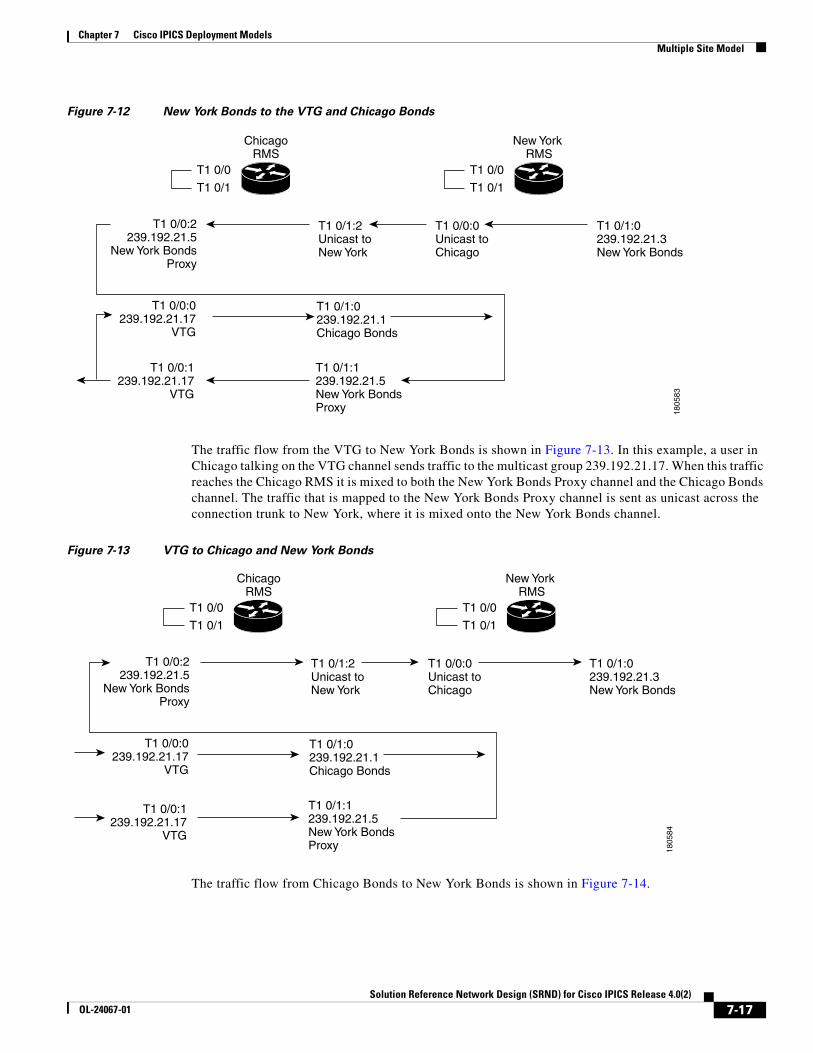
Chapter 7 Cisco IPICS Deployment ModelsMultiple Site Model
Figure 7-12 New York Bonds to the VTG and Chicago Bonds
The traffic flow from the VTG to New York Bonds is shown in Figure 7-13. In this example, a user in Chicago talking on the VTG channel sends traffic to the multicast group 239.192.21.17. When this traffic reaches the Chicago RMS it is mixed to both the New York Bonds Proxy channel and the Chicago Bonds channel. The traffic that is mapped to the New York Bonds Proxy channel is sent as unicast across the connection trunk to New York, where it is mixed onto the New York Bonds channel.
Figure 7-13 VTG to Chicago and New York Bonds
The traffic flow from Chicago Bonds to New York Bonds is shown in Figure 7-14.
ChicagoRMS
T1 0/0:1239.192.21.17
VTG
T1 0/1:0239.192.21.1Chicago Bonds
T1 0/1:2Unicast toNew York
T1 0/0:0Unicast toChicago
T1 0/1:0239.192.21.3New York Bonds
T1 0/0:0239.192.21.17
VTG
T1 0/0:2239.192.21.5
New York BondsProxy
T1 0/1:1239.192.21.5New York BondsProxy
T1 0/0
T1 0/1
New York RMS
T1 0/0
T1 0/1
1805
83
ChicagoRMS
T1 0/0:1239.192.21.17
VTG
T1 0/1:0239.192.21.1Chicago Bonds
T1 0/1:2Unicast toNew York
T1 0/0:0Unicast toChicago
T1 0/1:0239.192.21.3New York Bonds
T1 0/0:0239.192.21.17
VTG
T1 0/0:2239.192.21.5
New York BondsProxy
T1 0/1:1239.192.21.5New York BondsProxy
T1 0/0
T1 0/1
New York RMS
T1 0/0
T1 0/1
1805
84
7-17Solution Reference Network Design (SRND) for Cisco IPICS Release 4.0(2)
OL-24067-01
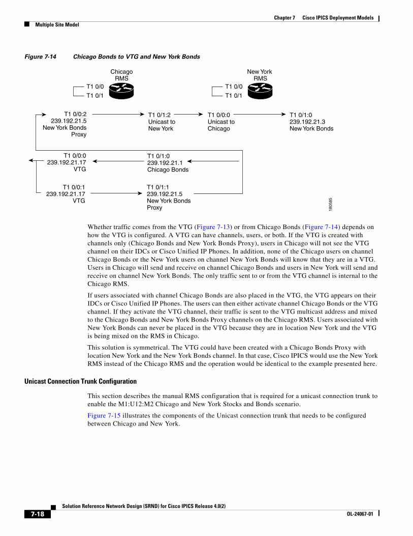
Chapter 7 Cisco IPICS Deployment ModelsMultiple Site Model
Figure 7-14 Chicago Bonds to VTG and New York Bonds
Whether traffic comes from the VTG (Figure 7-13) or from Chicago Bonds (Figure 7-14) depends on how the VTG is configured. A VTG can have channels, users, or both. If the VTG is created with channels only (Chicago Bonds and New York Bonds Proxy), users in Chicago will not see the VTG channel on their IDCs or Cisco Unified IP Phones. In addition, none of the Chicago users on channel Chicago Bonds or the New York users on channel New York Bonds will know that they are in a VTG. Users in Chicago will send and receive on channel Chicago Bonds and users in New York will send and receive on channel New York Bonds. The only traffic sent to or from the VTG channel is internal to the Chicago RMS.
If users associated with channel Chicago Bonds are also placed in the VTG, the VTG appears on their IDCs or Cisco Unified IP Phones. The users can then either activate channel Chicago Bonds or the VTG channel. If they activate the VTG channel, their traffic is sent to the VTG multicast address and mixed to the Chicago Bonds and New York Bonds Proxy channels on the Chicago RMS. Users associated with New York Bonds can never be placed in the VTG because they are in location New York and the VTG is being mixed on the RMS in Chicago.
This solution is symmetrical. The VTG could have been created with a Chicago Bonds Proxy with location New York and the New York Bonds channel. In that case, Cisco IPICS would use the New York RMS instead of the Chicago RMS and the operation would be identical to the example presented here.
Unicast Connection Trunk Configuration
This section describes the manual RMS configuration that is required for a unicast connection trunk to enable the M1:U12:M2 Chicago and New York Stocks and Bonds scenario.
Figure 7-15 illustrates the components of the Unicast connection trunk that needs to be configured between Chicago and New York.
ChicagoRMS
T1 0/0:1239.192.21.17
VTG
T1 0/1:0239.192.21.1Chicago Bonds
T1 0/1:2Unicast toNew York
T1 0/0:0Unicast toChicago
T1 0/1:0239.192.21.3New York Bonds
T1 0/0:0239.192.21.17
VTG
T1 0/0:2239.192.21.5
New York BondsProxy
T1 0/1:1239.192.21.5New York BondsProxy
T1 0/0
T1 0/1
New York RMS
T1 0/0
T1 0/1
1805
85
7-18Solution Reference Network Design (SRND) for Cisco IPICS Release 4.0(2)
OL-24067-01
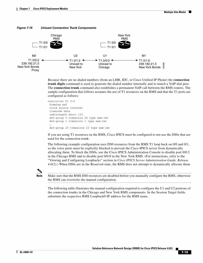
Chapter 7 Cisco IPICS Deployment ModelsMultiple Site Model
Figure 7-15 Unicast Connection Trunk Components
Because there are no dialed numbers (from an LMR, IDC, or Cisco Unified IP Phone) the connection trunk digits command is used to generate the dialed number internally and to match a VoIP dial peer. The connection trunk command also establishes a permanent VoIP call between the RMS routers. The sample configuration that follows assumes the use of T1 resources on the RMS and that the T1 ports are configured as follows:
controller T1 0/0 framing esf clock source internal linecode b8zs cablelength short 133 ds0-group 0 timeslots 24 type e&m-lmr ds0-group 1 timeslots 1 type e&m-lmr … ds0-group 23 timeslots 23 type e&m-lmr
If you are using T1 resources on the RMS, Cisco IPICS must be configured to not use the DS0s that are used for the connection trunk.
The following example configuration uses DS0 resources from the RMS T1 loop back on 0/0 and 0/1, so the voice ports must be explicitly blocked to prevent the Cisco IPICS server from dynamically allocating them. To block the DS0s, use the Cisco IPICS Administration Console to disable port 0/0:2 in the Chicago RMS and to disable port 0/0:0 in the New York RMS. (For instructions, refer to the “Viewing and Configuring Loopbacks” section in Cisco IPICS Server Administration Guide, Release 4.0(2).) When DS0s are in the Reserved state, the RMS does not attempt to dynamically allocate them.
Note Make sure that the RMS DS0 resources are disabled before you manually configure the RMS, otherwise the RMS can overwrite the manual configuration.
The following table illustrates the manual configuration required to configure the U1 and U2 portions of the connection trunks in the Chicago and New York RMS components. In the Session Target fields, substitute the respective RMS Loopback0 IP address for the RMS name.
ChicagoRMS
T1 0/1:2Unicast toNew York
T1 0/0:0Unicast toChicago
T1 0/1:0239.192.21.3New York Bonds
T1 0/0:2239.192.21.5
New York BondsProxy
T1 0/0
T1 0/1
New York RMS
T1 0/0
T1 0/1
1805
89
M2 M1U1U2
7-19Solution Reference Network Design (SRND) for Cisco IPICS Release 4.0(2)
OL-24067-01
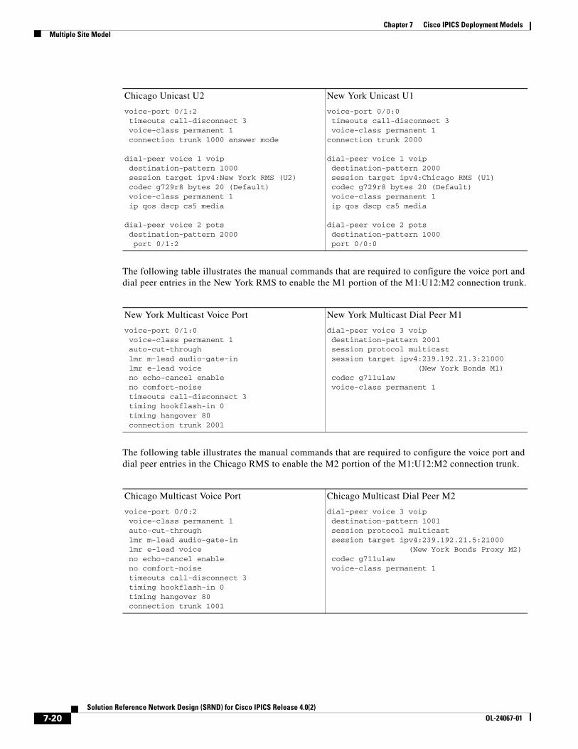
Chapter 7 Cisco IPICS Deployment ModelsMultiple Site Model
The following table illustrates the manual commands that are required to configure the voice port and dial peer entries in the New York RMS to enable the M1 portion of the M1:U12:M2 connection trunk.
The following table illustrates the manual commands that are required to configure the voice port and dial peer entries in the Chicago RMS to enable the M2 portion of the M1:U12:M2 connection trunk.
Chicago Unicast U2
voice-port 0/1:2 timeouts call-disconnect 3 voice-class permanent 1 connection trunk 1000 answer mode
dial-peer voice 1 voip destination-pattern 1000 session target ipv4:New York RMS (U2) codec g729r8 bytes 20 (Default) voice-class permanent 1 ip qos dscp cs5 media
dial-peer voice 2 pots destination-pattern 2000 port 0/1:2
New York Unicast U1
voice-port 0/0:0 timeouts call-disconnect 3 voice-class permanent 1connection trunk 2000
dial-peer voice 1 voip destination-pattern 2000 session target ipv4:Chicago RMS (U1) codec g729r8 bytes 20 (Default) voice-class permanent 1 ip qos dscp cs5 media
dial-peer voice 2 pots destination-pattern 1000 port 0/0:0
New York Multicast Voice Port
voice-port 0/1:0 voice-class permanent 1 auto-cut-through lmr m-lead audio-gate-in lmr e-lead voice no echo-cancel enable no comfort-noise timeouts call-disconnect 3 timing hookflash-in 0 timing hangover 80 connection trunk 2001
New York Multicast Dial Peer M1
dial-peer voice 3 voip destination-pattern 2001 session protocol multicast session target ipv4:239.192.21.3:21000 (New York Bonds M1) codec g711ulaw voice-class permanent 1
Chicago Multicast Voice Port
voice-port 0/0:2 voice-class permanent 1 auto-cut-through lmr m-lead audio-gate-in lmr e-lead voice no echo-cancel enable no comfort-noise timeouts call-disconnect 3 timing hookflash-in 0 timing hangover 80 connection trunk 1001
Chicago Multicast Dial Peer M2
dial-peer voice 3 voip destination-pattern 1001 session protocol multicast session target ipv4:239.192.21.5:21000 (New York Bonds Proxy M2) codec g711ulaw voice-class permanent 1
7-20Solution Reference Network Design (SRND) for Cisco IPICS Release 4.0(2)
OL-24067-01
Chapter 7 Cisco IPICS Deployment ModelsMultiple Site Model
Connection Trunk Verification
The following output shows the Cisco IOS commands that can be used in an RMS to determine the status of the connection trunk. This sample output shows the dial peers used and shows that the trunked connections are in the connected state.
New York#show voice call statusCallID CID ccVdb Port DSP/Ch Called # Codec Dial-peers0xF 11F0 0x6772A350 0/0:0.24 0/13:1 2000 g729r8 2/10x11 11F3 0x67729198 0/1:0.24 0/13:3 2001 g711ulaw 0/32 active calls found
Chicago#show voice call summary | i TRUNKED0/1:2.24 g729r8 y S_CONNECT S_TRUNKED0/0:2:0.24 g711ulaw y S_CONNECT S_TRUNKED
Bandwidth Considerations for Unicast Connection Trunks
Hoot ‘n’ holler mixing algorithms are described in Chapter 2, “Cisco IPICS Component Considerations” and bandwidth considerations and are described in Chapter 4, “Cisco IPICS Infrastructure Considerations.” To determine the bandwidth required for one unicast connection trunk, find the bandwidth requirement for one voice stream in Table 4-2 on page 4-6.
For example, using the G.729 codec, 20 byte payload size, and cRTP with VAD requires 7.3 kbps.
This calculation is the bandwidth for one connection trunk. If more than one connection trunk is used, multiple this number by the number of trunks.
Multicast Singularities
A multicast singularity is a restrictive case of the multicast island scenario. Between sites, multicast routing is not enabled. Within a site, multicast is enabled only on Cisco IPICS specific devices: RMS, LMR gateways, IDCs, and Cisco Unified IP Phones. These Cisco IPICS devices reside in a multicast singularity, as shown in Figure 7-16.
7-21Solution Reference Network Design (SRND) for Cisco IPICS Release 4.0(2)
OL-24067-01
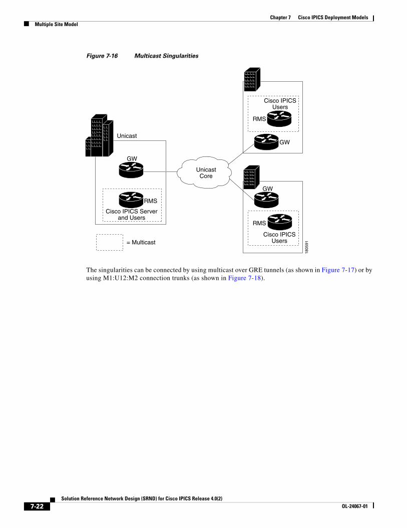
Chapter 7 Cisco IPICS Deployment ModelsMultiple Site Model
Figure 7-16 Multicast Singularities
The singularities can be connected by using multicast over GRE tunnels (as shown in Figure 7-17) or by using M1:U12:M2 connection trunks (as shown in Figure 7-18).
Cisco IPICSUsers
Cisco IPICSUsers
RMS
RMS
GW
GW
Cisco IPICS Serverand Users
= Multicast
RMS
GW
1805
91
Unicast
UnicastCore
7-22Solution Reference Network Design (SRND) for Cisco IPICS Release 4.0(2)
OL-24067-01
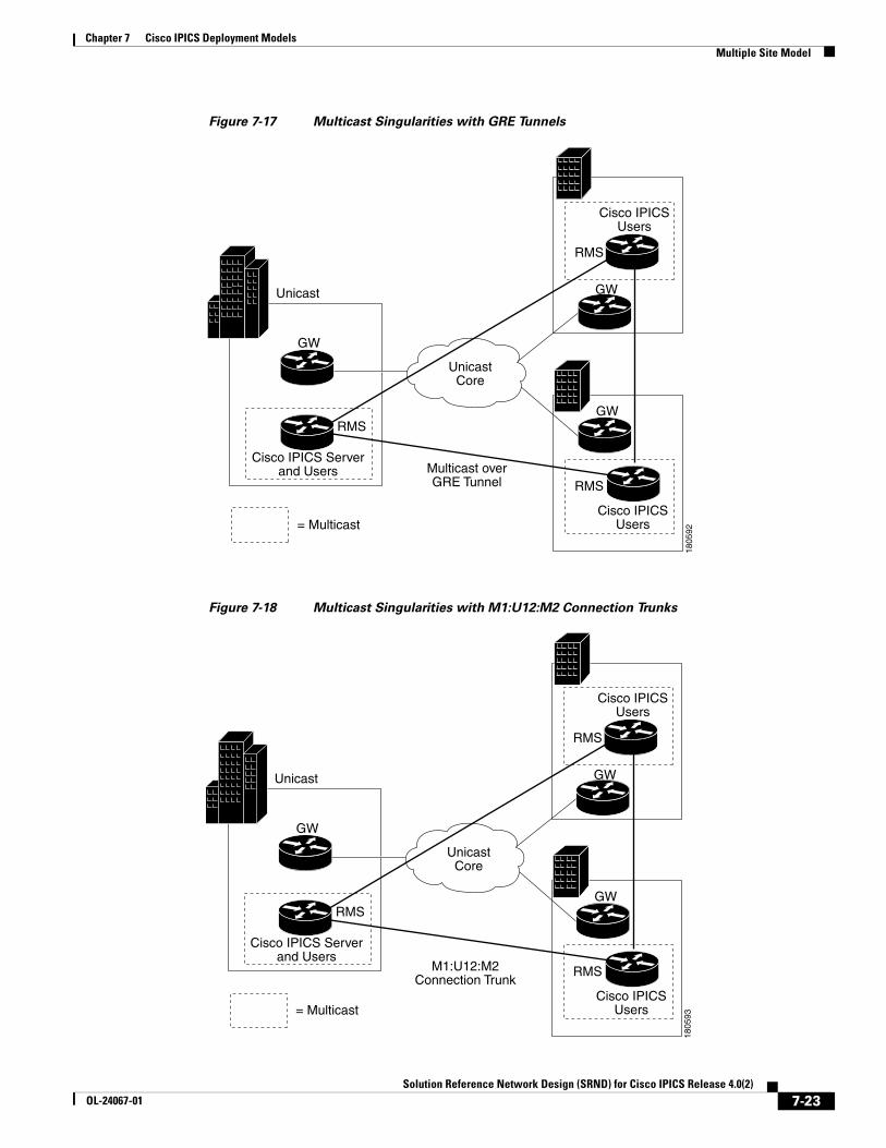
Chapter 7 Cisco IPICS Deployment ModelsMultiple Site Model
Figure 7-17 Multicast Singularities with GRE Tunnels
Figure 7-18 Multicast Singularities with M1:U12:M2 Connection Trunks
Cisco IPICS Serverand Users
Cisco IPICSUsers
Cisco IPICSUsers
= Multicast
Multicast overGRE Tunnel
RMS
RMS
RMS
GW
GW
GW
1805
92
Unicast
UnicastCore
Cisco IPICS Serverand Users
Cisco IPICSUsers
Cisco IPICSUsers
= Multicast
M1:U12:M2Connection Trunk
RMS
RMS
RMS
GW
GW
GW
1805
93
Unicast
UnicastCore
7-23Solution Reference Network Design (SRND) for Cisco IPICS Release 4.0(2)
OL-24067-01
Chapter 7 Cisco IPICS Deployment ModelsMultiple Site Model
The configuration of a multicast over GRE tunnel is identical to the multicast island scenario except the tunnel must be configured between the RMS routers and not the gateway routers because the gateway routers are not enabled for multicast.
The configuration of an M1:U12:M2 connection trunk is identical to the multicast islands scenario. In both cases, the trunk must be configured between the RMS routers.
The following rules apply to a multicast singularity:
1. All RMS and LMR gateways must reside in a multicast singularity. That is, these devices must be on directly connected multicast enabled LANs.
2. All users within the multicast singularity can use a IDC or a Cisco Unified IP Phone because they are in the multicast enabled zone.
3. Users outside the multicast singularity can use the IDC if they connect by using location Remote.
4. Users outside the multicast singularity cannot use the Cisco Unified IP Phone because this device supports only multicast.
It would be possible to have multiple multicast singularities within the same site and the singularities could be connected with multicast over GRE tunnels. This solution depends on the policies of the organization.
7-24Solution Reference Network Design (SRND) for Cisco IPICS Release 4.0(2)
OL-24067-01
Solution Reference NeOL-24067-01
C H A P T E R 8
High Latency and Low Bandwidth InterconnectionCisco IPICS provides support for environments that include high latency and low or variable bandwidth links, such as satellite links. In these types of environments, connectivity may become unstable because of the geographical location of the user, weather elements, and other interferences. Cisco IPICS compensates for these dynamically variable bandwidth scenarios and enhances its support for mobile operations.
Cisco IPICS supports the following deployment scenarios:
• Central site server solution—Supports a Cisco IPICS server that is installed at a central site and a distributed router media service (RMS) and end-user client components that are installed at a remote site.
• Remote locations solution—Supports deployment of the Cisco IPICS server, RMS, and end-user clients at two remote sites that are connected by M1:U12:M2 tunnels.
• Remote IDC solution—Supports a Cisco IPICS server and a distributed RMS at a central site and end-user IDC clients at a remote site.
Note With this deployment scenario, remote IDC clients must be configured to use the “Optimize for low bandwidth” setting in the IDC Settings > Channels menu. For information about how to configure the IDC for use in this deployment scenario, refer to the “Configuring the IDC Application” chapter in Cisco IPICS IDC Installation and User Guide, Release 4.0(2).
The M1:U12:M2 tunneling technology enables these deployment scenarios. For more information about these deployment scenarios, see the “Supported Deployment Solutions” section on page 8-2.
This chapter includes these topics:
• Supported Deployment Solutions, page 8-2
• Requirements and Support Information, page 8-4
• Performing Additional Configurations on the Cisco IPICS Server, page 8-5
• Performance Guidelines, page 8-8
8-1twork Design (SRND) for Cisco IPICS Release 4.0(2)
Chapter 8 High Latency and Low Bandwidth InterconnectionSupported Deployment Solutions
Supported Deployment SolutionsCisco IPICS enhancements include support for the deployment solutions that are described in the following topics:
• Central Site Server Solution, page 8-2
• Remote Locations Solution, page 8-3
• M1:U12:M2 Configuration Examples, page 8-3
Central Site Server SolutionIn the central site server solution, the Cisco IPICS server is located in a central site and an RMS is distributed with the IDC and other end-user clients in a remote site that is connected via a high latency, low bandwidth connection. In this situation, the Cisco IPICS server must control the distributed RMS, and the dispatcher at the central site needs to be able to communicate with remote IDC clients in the field.
This deployment solution provides the ability to remotely control the RMS over the high latency, low bandwidth links. Communications are enabled by the support of an M1:U12:M2 connection trunk between the RMS in the central site and a remotely-located RMS.
The M1:U12:M2 connection trunk also provides the capability for IP phone XML services and IDC clients to communicate between sites.
Note M1:U12:M2 (Multicast1:Unicast1-Unicast2:Multicast2) provides a unicast connection path between two multicast islands. An M1:U12:M2 connection trunk maps multicast to unicast on one side of the network, provides transport over the unicast wide area network (WAN) as a unicast Voice over IP (VoIP) call, and then converts it back to multicast on the other side of the connection, such that multicast 1 is connected to multicast 2 via a unicast connection between 1 and 2. M1:U12:M2 transports only the multicast traffic that is configured on the trunk as contrasted to Generic Routing Encapsulation (GRE) tunnels, which transports all multicast traffic.
See the “Performing Additional Configurations on the Cisco IPICS Server” section on page 8-5 for additional configurations that apply to this deployment.
Caveats
Be aware of the following caveats when you use the central site server deployment solution:
• Because all RMS commands flow over the high latency, low bandwidth link, this solution results in reduced throughput and slower response time.
• Some RMS-related operations may take over 3 minutes. Throughput considerations are based on factors such as the number of active channels that are included in the VTGs, the number of DS0s that are being used on the RMS, and the number of IDC users who are communicating between the sites. This limitation is due to inherent Transmission Control Protocol/Internet Protocol (TCP/IP) limitations over high latency, low bandwidth links. For information about RMS configuration updates when you use this deployment solution, see the “Updating the RMS Configuration” section on page 8-5.
• If you do not have a local router installed at the central site, you may need to configure Address Resolution Protocol (ARP) commands to increase the ARP timer so that the RMS remains reachable. For more information, see the “Adjusting ARP Commands” section on page 8-6.
8-2Solution Reference Network Design (SRND) for Cisco IPICS Release 4.0(2)
OL-24067-01
Chapter 8 High Latency and Low Bandwidth InterconnectionSupported Deployment Solutions
• The RMS and the Cisco IPICS server automatic synchronization mechanism must be disabled in this scenario. Therefore, you must manually synchronize these components. For more information about the manual configurations that you must perform, see the “Disabling the RMS Comparator” section on page 8-6 and the “Merging the Configuration” section on page 8-6.
• To conserve bandwidth, you must disable the IDC upload log frequency. For more information, see the “Disabling the IDC Upload Activity Log Frequency” section on page 8-7.
• Although the M1:U12:M2 connection trunk consumes dedicated bandwidth between the central site and the remote site, it does provide for bandwidth optimization by allowing transcoding to the G.729 codec.
• This deployment solution does not support the use of IP phone XML services at the remote locations. IP phone XML services are available only at the central site.
• There is no support for direct IDC access to the remote locations. The IDC clients can be at the remote site or the central site but they cannot remotely connect across sites.
Remote Locations SolutionIn the remote locations solution, a Cisco IPICS server, RMS, IDC, and other end-user clients are located at two remote sites. High latency, low bandwidth links that connect these remote sites enable communications flow.
This deployment enables communications by the use of fixed M1:U12:M2 tunnels that are configured between the channels that are hosted on each RMS at each remote site, such that each channel is mirrored on the other sites.
The M1:U12:M2 connection trunk also provides the capability for IP phone XML services and IDC clients to communicate between sites.
See the “Performing Additional Configurations on the Cisco IPICS Server” section on page 8-5 for additional configurations that apply to this deployment.
Caveats
Be aware of the following caveats when you use the remote locations deployment solution:
• The M1:U12:M2 connection trunks consume dedicated bandwidth between the remote sites, however bandwidth optimization is enabled by allowing transcoding to the G.729 codec.
• If you use several Cisco IPICS servers that each control their own RMS, care must be taken not to duplicate VTGs when defining channels. Because each channel is mirrored on the other remote site, audio loops can occur between the sites when you use the same VTGs at each site.
• This deployment provides support for IP phone XML services at either the central site or the remote sites. The IP phone XML services must be local to the site where they are deployed.
• There is no support for direct IDC access to the remote locations. The IDC clients can be at the remote site(s) or the central site, but they cannot remotely connect across the sites (they must be local to the site where they are deployed).
M1:U12:M2 Configuration ExamplesThe following tables provide configuration examples for the multicast portion of the M1:U12:M2 connection trunks.
8-3Solution Reference Network Design (SRND) for Cisco IPICS Release 4.0(2)
OL-24067-01
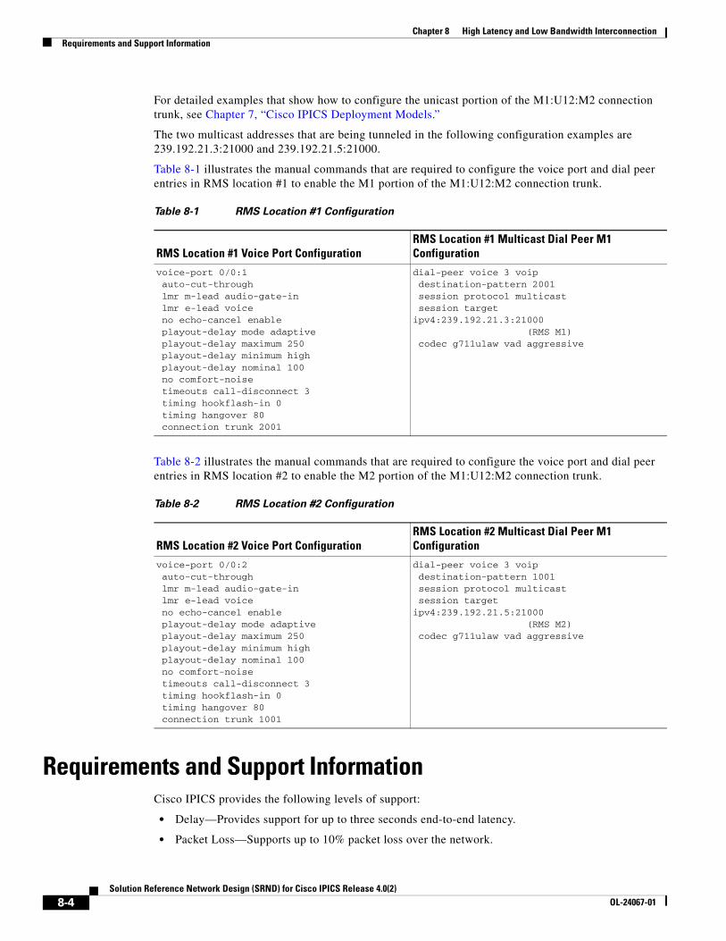
Chapter 8 High Latency and Low Bandwidth InterconnectionRequirements and Support Information
For detailed examples that show how to configure the unicast portion of the M1:U12:M2 connection trunk, see Chapter 7, “Cisco IPICS Deployment Models.”
The two multicast addresses that are being tunneled in the following configuration examples are 239.192.21.3:21000 and 239.192.21.5:21000.
Table 8-1 illustrates the manual commands that are required to configure the voice port and dial peer entries in RMS location #1 to enable the M1 portion of the M1:U12:M2 connection trunk.
Table 8-2 illustrates the manual commands that are required to configure the voice port and dial peer entries in RMS location #2 to enable the M2 portion of the M1:U12:M2 connection trunk.
Requirements and Support InformationCisco IPICS provides the following levels of support:
• Delay—Provides support for up to three seconds end-to-end latency.
• Packet Loss—Supports up to 10% packet loss over the network.
Table 8-1 RMS Location #1 Configuration
RMS Location #1 Voice Port ConfigurationRMS Location #1 Multicast Dial Peer M1 Configuration
voice-port 0/0:1 auto-cut-through lmr m-lead audio-gate-in lmr e-lead voice no echo-cancel enable playout-delay mode adaptive playout-delay maximum 250 playout-delay minimum high playout-delay nominal 100 no comfort-noise timeouts call-disconnect 3 timing hookflash-in 0 timing hangover 80 connection trunk 2001
dial-peer voice 3 voip destination-pattern 2001 session protocol multicast session targetipv4:239.192.21.3:21000 (RMS M1) codec g711ulaw vad aggressive
Table 8-2 RMS Location #2 Configuration
RMS Location #2 Voice Port ConfigurationRMS Location #2 Multicast Dial Peer M1 Configuration
voice-port 0/0:2 auto-cut-through lmr m-lead audio-gate-in lmr e-lead voice no echo-cancel enable playout-delay mode adaptive playout-delay maximum 250 playout-delay minimum high playout-delay nominal 100 no comfort-noise timeouts call-disconnect 3 timing hookflash-in 0 timing hangover 80 connection trunk 1001
dial-peer voice 3 voip destination-pattern 1001 session protocol multicast session targetipv4:239.192.21.5:21000 (RMS M2) codec g711ulaw vad aggressive
8-4Solution Reference Network Design (SRND) for Cisco IPICS Release 4.0(2)
OL-24067-01
Chapter 8 High Latency and Low Bandwidth InterconnectionPerforming Additional Configurations on the Cisco IPICS Server
• Jitter buffer—Enables support for up to 250 ms of maximum jitter on the network (to support burst latency).
• Link outages—Provides support for temporary link outages so that if the connection from the IDC is interrupted, the connection automatically continues when it becomes available again. (The IDC user is not informed of the outage.)
• Bandwidth—Supports 64 kbps bandwidth per channel configured over an M1:U12:M2 connection trunk.
Caveat
The first time that the IDC logs in to the server, an error message displays to inform the user that the channels are being disabled. This error occurs because of the time delay to connect. To recover from this error, click OK. After the server completes its tasks, the channels will display on the IDC (this timing will vary based on latency).
Performing Additional Configurations on the Cisco IPICS ServerThe following additional configurations are required when you use the central site server or the remote locations deployment solution:
• Updating the RMS Configuration, page 8-5
• Adjusting ARP Commands, page 8-6
• Disabling the RMS Comparator, page 8-6
• Merging the Configuration, page 8-6
• Disabling the IDC Upload Activity Log Frequency, page 8-7
Updating the RMS ConfigurationWhen you use the central site or the remote locations deployment solution, you must update every RMS that is configured with Cisco IPICS and that is used over a high latency, low bandwidth connection. This configuration update modifies the maximum TCP outgoing queue on a per-connection basis.
To modify the maximum TCP outgoing queue, perform the following procedure on each RMS:
Procedure
Step 1 Enter global configuration mode by entering the following command:
Router# configure terminal
Step 2 To set the maximum TCP outgoing queue to 100000 packets, enter the following command:
Router(config)# ip tcp queuemax 100000
Step 3 To save your configuration, enter the following command:
Router(config)# write mem
Step 4 To exit the router configuration mode, enter the following command:
Router# exit
8-5Solution Reference Network Design (SRND) for Cisco IPICS Release 4.0(2)
OL-24067-01
Chapter 8 High Latency and Low Bandwidth InterconnectionPerforming Additional Configurations on the Cisco IPICS Server
Adjusting ARP CommandsIf you use the central site server solution and you do not have a local router installed at the central site, you may need to increase the ARP timer in the server. This adjustment helps to prevent timeouts and to ensure reachability between the server and the RMS when these components are connected via Ethernet and separated by a high latency link.
If you encounter issues with ARP timeouts and ping response times, contact the Cisco Technical Assistance Center.
Disabling the RMS ComparatorThe RMS comparator is the mechanism that checks the responsiveness of the RMS and checks whether there have been changes made to the configuration. If there have been changes to the RMS configuration and these changes are not reflected in the Cisco IPICS server, the RMS comparator automatically updates the configuration so that the two components are synchronized.
Because this synchronization mechanism can interject delay, the RMS comparator needs to be manually disabled. To disable the RMS comparator, perform the following procedure.
Note This change is a global change and affects all RMS components that are configured in the server.
Procedure
Step 1 Log in to Cisco IPICS the server as a system administrator.
Step 2 From the Administration Console, choose Administration > Options.
Step 3 From the General tab, check the Disable RMS Comparator check box that is located in the RMS pane.
This change disables the RMS comparator so that it does not run.
Step 4 Click Save to save your change.
Step 5 In the RMS pane, verify that the Disable RMS Comparator check box is checked and that the RMS Polling Frequency field is dimmed.
Merging the ConfigurationAfter you have disabled the RMS comparator, you must merge the configuration to make sure that the router is synchronized with the server.
Note As a best practice, make sure that you merge the RMS configuration whenever manual changes have been made to the RMS. This process ensures that the components are synchronized. Perform this procedure before you perform any configuration changes, such as activating a VTG.
To merge the configuration, perform the following procedure:
8-6Solution Reference Network Design (SRND) for Cisco IPICS Release 4.0(2)
OL-24067-01
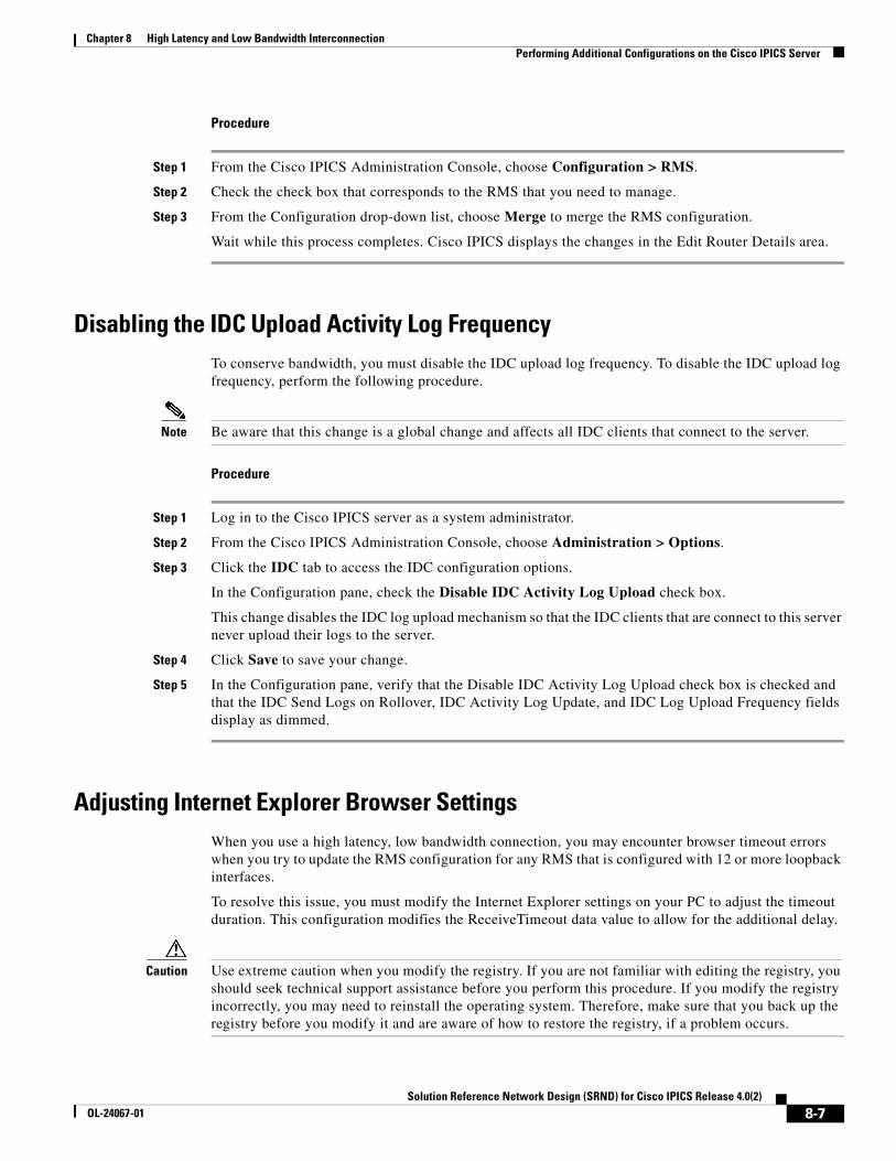
Chapter 8 High Latency and Low Bandwidth InterconnectionPerforming Additional Configurations on the Cisco IPICS Server
Procedure
Step 1 From the Cisco IPICS Administration Console, choose Configuration > RMS.
Step 2 Check the check box that corresponds to the RMS that you need to manage.
Step 3 From the Configuration drop-down list, choose Merge to merge the RMS configuration.
Wait while this process completes. Cisco IPICS displays the changes in the Edit Router Details area.
Disabling the IDC Upload Activity Log FrequencyTo conserve bandwidth, you must disable the IDC upload log frequency. To disable the IDC upload log frequency, perform the following procedure.
Note Be aware that this change is a global change and affects all IDC clients that connect to the server.
Procedure
Step 1 Log in to the Cisco IPICS server as a system administrator.
Step 2 From the Cisco IPICS Administration Console, choose Administration > Options.
Step 3 Click the IDC tab to access the IDC configuration options.
In the Configuration pane, check the Disable IDC Activity Log Upload check box.
This change disables the IDC log upload mechanism so that the IDC clients that are connect to this server never upload their logs to the server.
Step 4 Click Save to save your change.
Step 5 In the Configuration pane, verify that the Disable IDC Activity Log Upload check box is checked and that the IDC Send Logs on Rollover, IDC Activity Log Update, and IDC Log Upload Frequency fields display as dimmed.
Adjusting Internet Explorer Browser SettingsWhen you use a high latency, low bandwidth connection, you may encounter browser timeout errors when you try to update the RMS configuration for any RMS that is configured with 12 or more loopback interfaces.
To resolve this issue, you must modify the Internet Explorer settings on your PC to adjust the timeout duration. This configuration modifies the ReceiveTimeout data value to allow for the additional delay.
Caution Use extreme caution when you modify the registry. If you are not familiar with editing the registry, you should seek technical support assistance before you perform this procedure. If you modify the registry incorrectly, you may need to reinstall the operating system. Therefore, make sure that you back up the registry before you modify it and are aware of how to restore the registry, if a problem occurs.
8-7Solution Reference Network Design (SRND) for Cisco IPICS Release 4.0(2)
OL-24067-01

Chapter 8 High Latency and Low Bandwidth InterconnectionPerformance Guidelines
Tip For more information about how to back up, restore, and modify the registry, access the Microsoft Support site and search the Microsoft Knowledge Base for a description of the Microsoft Windows registry.
To modify the ReceiveTimeout data value, perform the following procedure on the PC that you use to access the Cisco IPICS Administration Console:
Procedure
Step 1 On the PC that you use to access the Administration Console, choose Start > Run.
Step 2 In the Open dialog box, enter regedit.
The Registry Editor displays.
Step 3 Click the + sign that displays next to the HKEY_CURRENT_USER entry.
The folders that contain root configuration information for the user who is currently logged in displays.
Step 4 Click the + signs that display next to each of the folder names to navigate to the Software\Microsoft\Windows\CurrentVersion\ folder.
Step 5 Click the + sign that displays next to the Internet Settings folder.
At this point, you have navigated to this folder: HKEY_CURRENT_USER\Software\Microsoft\Windows\CurrentVersion\Internet Settings.
Step 6 In the Internet Settings folder, look for the ReceiveTimeout name.
Step 7 To modify this setting, right-click the ReceiveTimeout name, then click Modify.
The Edit DWORD Value dialog box displays. The current DWORD value displays in hexadecimal format.
Alternatively, you can choose to delete the ReceiveTimeout name by clicking Delete. If you take this action, be aware that you could wait indefinitely for the server to respond.
Step 8 Click the Decimal radio button to display this value in decimal format.
Step 9 To configure this value to the recommended setting to accommodate high latency, low bandwidth links, enter 480000 in the Value data field.
This modification configures the timeout value to 8 minutes.
Step 10 Click OK to save your change.
Step 11 To exit the Registry Editor, choose Registry > Exit.
Step 12 Restart your PC for the change to become effective.
Performance GuidelinesBe aware of the following guidelines:
• Each RMS can support a predefined number of commands, such as VTG activation, VTG deactivation, and IDC SIP (remote) connections. If the number of commands that the RMS receives exceeds this threshold, the excess commands fail and must be resubmitted.
8-8Solution Reference Network Design (SRND) for Cisco IPICS Release 4.0(2)
OL-24067-01

Chapter 8 High Latency and Low Bandwidth InterconnectionPerformance Guidelines
• For high latency, low bandwidth deployments, allow 1.5 minutes for every three channel/VTG activations.
• If five dispatchers submit commands, or if the same dispatcher submits several commands, a wait time of 1.5 minutes should be allotted before resubmitting new command requests.
• For constant load conditions, a frequency of about 18 seconds per simple VTG command should be allotted on 2811 routers (RMS components), on average. Additional RMS components must be installed to support above average load conditions.
8-9Solution Reference Network Design (SRND) for Cisco IPICS Release 4.0(2)
OL-24067-01

Chapter 8 High Latency and Low Bandwidth InterconnectionPerformance Guidelines
8-10Solution Reference Network Design (SRND) for Cisco IPICS Release 4.0(2)
OL-24067-01

Solution Reference NeOL-24067-01
G L O S S A R Y
A
action A discrete function that is performed through a policy. Discrete functions include activate VTG, notification, VTG add participant, dial-out, and invite to VTG.
activate VTG An action that activates a preconfigured VTG; can also specify a duration. At the end of the specified duration, the VTG is deactivated. If no duration is specified, the VTG must be manually deactivated by the dispatcher from the VTG Management drawer in the Cisco IPICS administration console.
activated A state that indicates that the SIP (unicast) or multicast channel is fully operational. When a channel/VTG on the IDC is enabled and activated, all of the IDC buttons are operational.
activating A state that becomes effective when you click the Activate button on the IDC. The Activate button appears highlighted while the other IDC buttons remain in an inactive state as the system attempts to activate and connect.
activation button This button toggles activate and deactivate functionality on the IDC. Click this button on the IDC to activate a channel (to call out); click it again to deactivate the channel.
active virtual talk
group
A virtual talk group (VTG) becomes active when Cisco IPICS commits global resources, such as a multicast address and any necessary dial-in peers, so that the participants in the VTG can communicate with each other.
Administration
Console
The graphical user interface (GUI) in the Cisco IPICS server software through which authorized Cisco IPICS users can manage and configure Cisco IPICS resources, events and VTGs.
alert tone An audible tone, such as a siren, warble or chirp, that is used to attract the attention of a radio listener.
alert tone buttons Buttons on the IDC that can play out alert tones on one channel or multiple channels.
all talk button Allows you to simultaneously talk on all of the channels that you selected.
autonomous
system
A radio system under one administrative control; also known as a management domain. This system is usually mapped to an agency.
B
backward
compatibility
The ability of newer radio equipment to operate within an older system infrastructure or to directly intercommunicate with an older radio unit. The term usually applies to digital radios that are also capable of analog signal transmission.
GL-1twork Design (SRND) for Cisco IPICS Release 4.0(2)
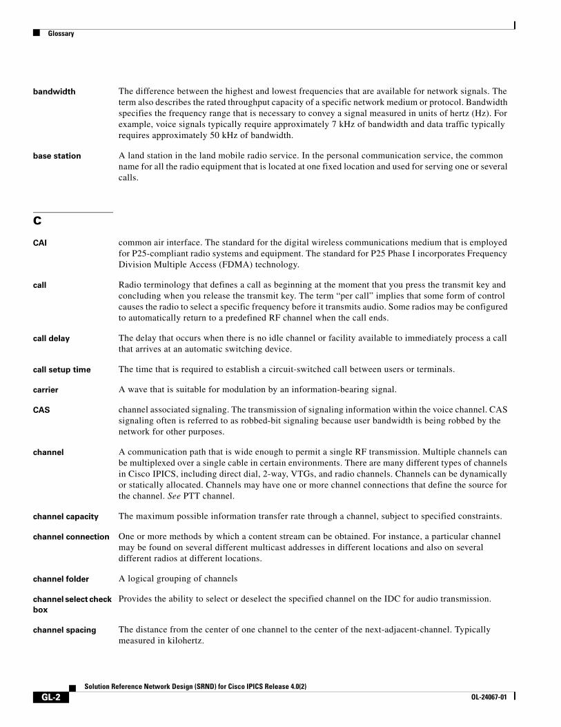
Glossary
bandwidth The difference between the highest and lowest frequencies that are available for network signals. The term also describes the rated throughput capacity of a specific network medium or protocol. Bandwidth specifies the frequency range that is necessary to convey a signal measured in units of hertz (Hz). For example, voice signals typically require approximately 7 kHz of bandwidth and data traffic typically requires approximately 50 kHz of bandwidth.
base station A land station in the land mobile radio service. In the personal communication service, the common name for all the radio equipment that is located at one fixed location and used for serving one or several calls.
C
CAI common air interface. The standard for the digital wireless communications medium that is employed for P25-compliant radio systems and equipment. The standard for P25 Phase I incorporates Frequency Division Multiple Access (FDMA) technology.
call Radio terminology that defines a call as beginning at the moment that you press the transmit key and concluding when you release the transmit key. The term “per call” implies that some form of control causes the radio to select a specific frequency before it transmits audio. Some radios may be configured to automatically return to a predefined RF channel when the call ends.
call delay The delay that occurs when there is no idle channel or facility available to immediately process a call that arrives at an automatic switching device.
call setup time The time that is required to establish a circuit-switched call between users or terminals.
carrier A wave that is suitable for modulation by an information-bearing signal.
CAS channel associated signaling. The transmission of signaling information within the voice channel. CAS signaling often is referred to as robbed-bit signaling because user bandwidth is being robbed by the network for other purposes.
channel A communication path that is wide enough to permit a single RF transmission. Multiple channels can be multiplexed over a single cable in certain environments. There are many different types of channels in Cisco IPICS, including direct dial, 2-way, VTGs, and radio channels. Channels can be dynamically or statically allocated. Channels may have one or more channel connections that define the source for the channel. See PTT channel.
channel capacity The maximum possible information transfer rate through a channel, subject to specified constraints.
channel connection One or more methods by which a content stream can be obtained. For instance, a particular channel may be found on several different multicast addresses in different locations and also on several different radios at different locations.
channel folder A logical grouping of channels
channel select check
box
Provides the ability to select or deselect the specified channel on the IDC for audio transmission.
channel spacing The distance from the center of one channel to the center of the next-adjacent-channel. Typically measured in kilohertz.
GL-2Solution Reference Network Design (SRND) for Cisco IPICS Release 4.0(2)
OL-24067-01
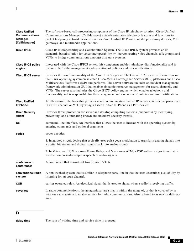
Glossary
Cisco Unified
Communications
Manager
(CallManager)
The software-based call-processing component of the Cisco IP telephony solution. Cisco Unified Communications Manager (CallManager) extends enterprise telephony features and functions to packet telephony network devices, such as Cisco Unified IP Phones, media processing devices, VoIP gateways, and multimedia applications.
Cisco IPICS Cisco IP Interoperability and Collaboration System. The Cisco IPICS system provides an IP standards-based solution for voice interoperability by interconnecting voice channels, talk groups, and VTGs to bridge communications amongst disparate systems.
Cisco IPICS policy
engine
Integrated with the Cisco IPICS server, this component enables telephony dial functionality and is responsible for the management and execution of policies and user notifications.
Cisco IPICS server Provides the core functionality of the Cisco IPICS system. The Cisco IPICS server software runs on the Linux operating system on selected Cisco Media Convergence Server (MCS) platforms and Cisco Multiservices Platforms (MSP) and performs. The server software includes an incident management framework administration GUI that enables dynamic resource management for users, channels, and VTGs. The server also includes the Cisco IPICS policy engine, which enables telephony dial functionality and is responsible for the management and execution of policies and user notifications.
Cisco Unified
IP Phone
A full-featured telephone that provides voice communication over an IP network. A user can participate in a PTT channel or VTG by using a Cisco Unified IP Phone as a PTT device.
Cisco Security
Agent
Provides threat protection for server and desktop computing systems (endpoints) by identifying, preventing, and eliminating known and unknown security threats.
CLI command-line interface. An interface that allows the user to interact with the operating system by entering commands and optional arguments.
codec coder-decoder.
1. Integrated circuit device that typically uses pulse code modulation to transform analog signals into a digital bit stream and digital signals back into analog signals.
2. In Voice over IP, Voice over Frame Relay, and Voice over ATM, a DSP software algorithm that is used to compress/decompress speech or audio signals.
conference of
conferences
A conference that consists of two or more VTGs.
conventional radio
system
A non-trunked system that is similar to telephone party-line in that the user determines availability by listening for an open channel.
COR carrier operated relay. An electrical signal that is used to signal when a radio is receiving traffic.
coverage In radio communications, the geographical area that is within the range of, or that is covered by, a wireless radio system to enable service for radio communications. Also referred to as service delivery area.
D
delay time The sum of waiting time and service time in a queue.
GL-3Solution Reference Network Design (SRND) for Cisco IPICS Release 4.0(2)
OL-24067-01
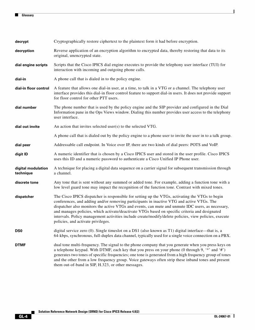
Glossary
decrypt Cryptographically restore ciphertext to the plaintext form it had before encryption.
decryption Reverse application of an encryption algorithm to encrypted data, thereby restoring that data to its original, unencrypted state.
dial engine scripts Scripts that the Cisco IPICS dial engine executes to provide the telephony user interface (TUI) for interaction with incoming and outgoing phone calls.
dial-in A phone call that is dialed in to the policy engine.
dial-in floor control A feature that allows one dial-in user, at a time, to talk in a VTG or a channel. The telephony user interface provides this dial-in floor control feature to support dial-in users. It does not provide support for floor control for other PTT users.
dial number The phone number that is used by the policy engine and the SIP provider and configured in the Dial Information pane in the Ops Views window. Dialing this number provides user access to the telephony user interface.
dial out invite An action that invites selected user(s) to the selected VTG.
A phone call that is dialed out by the policy engine to a phone user to invite the user in to a talk group.
dial peer Addressable call endpoint. In Voice over IP, there are two kinds of dial peers: POTS and VoIP.
digit ID A numeric identifier that is chosen by a Cisco IPICS user and stored in the user profile. Cisco IPICS uses this ID and a numeric password to authenticate a Cisco Unified IP Phone user.
digital modulation
technique
A technique for placing a digital data sequence on a carrier signal for subsequent transmission through a channel.
discrete tone Any tone that is sent without any summed or added tone. For example, adding a function tone with a low level guard tone may impact the recognition of the function tone. Contrast with mixed tones.
dispatcher The Cisco IPICS dispatcher is responsible for setting up the VTGs, activating the VTGs to begin conferences, and adding and/or removing participants in inactive VTG and active VTGs. The dispatcher also monitors the active VTGs and events, can mute and unmute IDC users, as necessary, and manages policies, which activate/deactivate VTGs based on specific criteria and designated intervals. Policy management activities include create/modify/delete policies, view policies, execute policies, and activate privileges.
DS0 digital service zero (0). Single timeslot on a DS1 (also known as T1) digital interface—that is, a 64-kbps, synchronous, full-duplex data channel, typically used for a single voice connection on a PBX.
DTMF dual tone multi-frequency. The signal to the phone company that you generate when you press keys on a telephone keypad. With DTMF, each key that you press on your phone (0 through 9, ‘*’ and ‘#’) generates two tones of specific frequencies; one tone is generated from a high frequency group of tones and the other from a low frequency group. Voice gateways often strip these inband tones and present them out-of-band in SIP, H.323, or other messages.
GL-4Solution Reference Network Design (SRND) for Cisco IPICS Release 4.0(2)
OL-24067-01

Glossary
dynamic radio
channel (dynamic
control)
The controls that are used to preset radio characteristics so that channels are available to clients.
dynamic regrouping A trunking system feature that allows multiple radios to be placed upon a specific talk group without manual manipulation of the programming of the radios. Dynamic regrouping is initiated through a system control console and transmitted to the radio via the trunking systems control channel.
E
E & M recEive and transMit (or ear and mouth). As the analog interface between a radio and the LMR gateway, the E&M interface provides voice signals from radio channels, which are then mapped to IP multicast or unicast. The E&M interface provides the most common form of analog trunking.
1. Trunking arrangement that is generally used for two-way switch-to-switch or switch-to-network connections. Cisco's analog E&M interface is an RJ-48 connector that allows connections to PBX trunk lines (tie lines). E&M also is available on E1 and T1 digital interfaces.
2. A type of signaling that is traditionally used in the telecommunications industry. Indicates the use of a handset that corresponds to the ear (receiving) and mouth (transmitting) component of a telephone.
e-lead The ear portion of the E & M interface. The e-lead is the receive path of the LMR gateway.
encipher To convert plain text into an unintelligible form by using a cipher.
encode To modify information into the required transmission format.
encryption Application of a specific algorithm so as to alter the appearance of data and make it incomprehensible to unauthorized users.
event An active VTG in the Cisco IPICS solution.
F
FDM frequency-division multiplexing. Technique whereby information from multiple channels can be allocated bandwidth on a single wire based on frequency.
FDMA frequency-division multiple access. A a channel access method in which different conversations are separated onto different frequencies. FDMA is employed in narrowest bandwidth and multiple-licensed channel operations.
FLEXlm Cisco software that enforces licensing on certain systems; FLEXlm ensures that Cisco IPICS software will work only on the supported and licensed hardware.
floor control The standard mechanism for Push-to-Talk speaker arbitration.
frame A logical grouping of information sent as a data link layer unit over a transmission medium. Often refers to the header and the trailer, used for synchronization and error control, that surround the user data contained in the unit. The terms cell, datagram, message, packet, and segment also describe logical information groupings at various layers of the OSI reference model.
GL-5Solution Reference Network Design (SRND) for Cisco IPICS Release 4.0(2)
OL-24067-01
Glossary
frequency For a periodic function, frequency represents the number of cycles or events per unit of time. Frequency is used in several different contexts. For example, transmission frequency (the band on which the radio sends signals) or the frequency of an audible signal measured in hertz (Hz). All tone control operations require audible tones that fall within a narrow band of a specific frequency and at a specific volume (amplitude).
frequency
assignment
Assignment that is given to a radio station to use a radio frequency or radio frequency channel under specified conditions.
frequency hopping The repeated switching of frequencies during radio transmission according to a specified algorithm, intended to minimize unauthorized interception or jamming of telecommunications.
frequency
modulation
Modulation technique in which signals of different frequencies represent different data values.
frequency sharing The assignment to or use of the same radio frequency by two or more stations that are separated geographically or that use the frequency at different times.
function tone A tone that follows the high level guard tone and causes the radio to perform a specific function, such as selecting a new transmit frequency. Function tones are often referred to as F1, F2, F3, and so on. See preamble and high level guard tone.
G
gateway Device that performs an application-layer conversion of information from one protocol stack to another. In Cisco IPICS, the gateway component includes LMR gateways, which functionality is usually installed as an additional feature in a supported Cisco router. LMR gateways provide voice interoperability between radio and non-radio networks by bridging radio frequencies to IP multicast streams.
GRE generic routing encapsulation. Tunneling protocol that can encapsulate a wide variety of protocol packet types inside IP tunnels, creating a virtual point-to-point link to Cisco routers at remote points over an IP internetwork. By connecting multiprotocol subnetworks in a single-protocol backbone environment, IP tunneling that uses GRE allows network expansion across a single-protocol backbone environment. GRE is generally used to route multicast traffic between routers.
guard tone The most common guard tones are the high level guard tone (HLGT) and the low level guard tone (LLGT). The HLGT is used to alert the radio that a function tone follows. The LLGT is used as a hold tone or keying tone. See tone keyed.
H
H.323 Defines a common set of codecs, call setup and negotiating procedures, and basic data transport methods to allow dissimilar communication devices to communicate with each other by using a standardized communication protocol.
high-band
frequency
Refers to the higher frequency levels in the VHF band, typically 138-222 MHz.
GL-6Solution Reference Network Design (SRND) for Cisco IPICS Release 4.0(2)
OL-24067-01
Glossary
HLGT high level guard done. Also known as awake tone. This tone is set at high volume and is usually the first tone in a preamble. It is used to alert the radio that another tone, usually a function tone, will follow. See guard tone.
Hoot ‘n’ Holler
(Hootie)
A communications system where the loudest and most recent talker or talkers are mixed into one multicast output stream. Also known as hootie, these networks provide “always on” multiuser conferences without requiring that users dial in to a conference.
Cisco enables the Cisco Hoot 'n' Holler feature in specific Cisco IOS versions.
I
IDC A component of Cisco IPCS that enables management of Cisco IPICS resources and control of incidents through an on-screen interface that runs on a client PC. This application allows users to communicate with other users via radio, telephone, mobile device, or PC; participate in VTGs and incidents; manage and operate a variety of resources (including channels, radios, incidents, and VTGs); and perform a variety of other activities
IDC ID The unique ID that the Cisco IPICS server generates for each IDC to track requests between the IDC and the server and to verify and manage concurrent IDC use for licensing requirements.
idle tone The tone that a radio may deliver on the m-lead to signal the LMR gateway that there is no incoming traffic. When the idle tone is removed, the LMR gateway deems all signals to be valid voice traffic.
inactive VTG A VTG that is stored for use. The Cisco IPICS server stores inactive VTGs with the information that you enter so that they can be automatically activated by a policy or manually activated by a dispatcher.
inband Traffic that is sent inband is included in the same stream as the real-time traffic protocol (RTP). Inband signals can be encoded signals and RFC 2833 signals.
incident An event that you create in the IDC and for which various users can coordinate responses by using the IDC.
incident VTG A temporary talk group for an incident.
informix linux group Members of this group have full permission to Cisco IPICS server folders, files, and scripts that are related to the Informix database application. Members of this group include the informix and ipicsdba users.
informix user ID The Cisco IPICS Linux user that belongs to both the informix linux group, which includes full permission to the Cisco IPICS database server folders, files, and scripts, and the ipics linux group, which includes permission to Cisco IPICS application-related folders, files, and scripts. In addition, this user has full administrative permission to the Informix database instance. Cisco IPICS creates this Linux system user ID and generates the password during the software installation process. The password for this user ID never expires.
To access the informix user, log in to the Cisco IPICS server by using the root user ID; then, enter su - informix (superuser from root).
GL-7Solution Reference Network Design (SRND) for Cisco IPICS Release 4.0(2)
OL-24067-01
Glossary
interference The effect of unwanted energy due to one or a combination of emissions, radiation, or inductions upon reception in a radio communication system, manifested by any performance degradation, misinterpretation, or loss of information, which could be extracted in the absence of such unwanted energy.
interoperability The capability of equipment manufactured by different vendors to communicate with each other successfully over a network.
invitation policy A policy that can be invoked only through the telephony user interface and can include only the invite to VTG action. After joining a talk group, a user can access the breakout menu and invoke invitation policies. The talk group that this user has joined is the talk group that the invited users join.
invite to VTG A version of the dial out invite action where users to be invited are preconfigured but the VTG that they are invited to depends on which VTG the invoker of the policy is dialed into.
ipicsadmin user ID The Cisco IPICS Linux user that, as part of the ipics linux group, has full permission to the Cisco IPICS server folders, files, and scripts that are related to the Cisco IPICS application and database backup and restore operations. In addition, the ipicsadmin user has permission to read and write data from and/or to the Informix database. Cisco IPICS creates this Linux system user ID during the software installation process. The password for this user ID never expires.
ipicsdba user ID The Cisco IPICS Linux user that belongs to both the informix linux group, which includes full permission to the Cisco IPICS database server folders, files, and scripts, and the ipics linux group, which includes permission to Cisco IPICS application-related folders, files, and scripts. In addition, the ipicsdba user has permission to read data, write data, create tables, and create databases in the Informix database instance. Cisco IPICS creates this Linux system user ID and generates the password during the software installation process. The password for this user ID never expires.
To access the ipicsdba user, log in to the Cisco IPICS server by using the root user ID; then, enter su - ipicsdba (superuser from root).
ipics linux group Members of this group have full permission to Cisco IPICS server folders, files, and scripts that are related to the Cisco IPICS application and database backup and restore operations. Members of this group include the ipicsadmin, ipicsdba, and informix users.
ipics user ID The Cisco IPICS application-level user ID that can perform all administration-related tasks via the Cisco IPICS Administration Console. Cisco IPICS creates this web-based user ID during the software installation process.
IPSec IP Security. A framework of open standards that provides data confidentiality, data integrity, and data authentication between participating peers. IPSec provides these security services at the IP layer. IPSec uses IKE to handle the negotiation of protocols and algorithms based on local policy and to generate the encryption and authentication keys to be used by IPSec. IPSec can protect one or more data flows between a pair of hosts, between a pair of security gateways, or between a security gateway and a host.
K
keepalive A message that is sent by one network device to inform another network device that the virtual circuit between the two devices is still active.
GL-8Solution Reference Network Design (SRND) for Cisco IPICS Release 4.0(2)
OL-24067-01
Glossary
key The parameter that defines an encryption code or method.
Key (a radio) causes the radio to transmit. See tone keyed.
kilohertz (kHz) A unit of frequency that denotes one thousand Hz.
L
latch The IDC functionality that allows a Cisco IPICS user to lock in a PTT channel.
linear modulation A radio frequency transmission technique that provides the physical transport layer of a radio system. This technology is compatible in digital and analog system environments and supports channel bandwidths of 5 kHz to 50 kHz.
LLGT low level guard tone. This tone is used as a hold tone or keying tone. See guard tone.
LMR Land Mobile Radio. A Land Mobile Radio (LMR) system is a collection of portable and stationary radio units that are designed to communicate with each other over predefined frequencies. They are deployed wherever organizations need to have instant communication between geographically dispersed and mobile personnel.
This term is often used interchangeably between a handheld or vehicle-mounted device and a stationary transmitter. Stationary devices are typically referred to as base stations.
Cisco IPICS leverages the Cisco Hoot 'n' Holler feature, which is enabled in specific Cisco IOS versions, to provide radio integration into the Cisco IPICS solution. LMR is integrated by providing an ear and mouth (E&M) interface to a radio or other PTT devices, such as Nextel phones. Configured as a voice port, this interface provides the appropriate electrical interface to the radio. You configure this voice port with a connection trunk entry that corresponds to a voip dial peer, which in turn associates the connection to a multicast address. This configuration allows you to configure a corresponding channel in Cisco IPICS, using the same multicast address, which enables Cisco IPICS to provide communication paths between the desired endpoints.
LMR gateway Land Mobile Radio gateway. Refers to the router E&M interface that converts IP traffic from digital to analog for use by radios.
location In Cisco IPICS, location signifies reachability; meaning, channels or users who are associated with the same location can communicate with each other without additional network configuration. Location may refer to a physical or virtual location, as defined in the server.
low-band frequency Lower frequency levels in the VHF band, typically 25–50 MHz.
M
megahertz (MHz) A unit of frequency denoting one million Hz.
mixed tone Two tones that are mixed together. DTMF is an example of a mixed tone. To be transmitted properly, tone signals must be mixed with the LLGT. See DTMF.
m-lead The mouth portion of the E&M interface. The m-lead is the transmit path of the LMR gateway.
GL-9Solution Reference Network Design (SRND) for Cisco IPICS Release 4.0(2)
OL-24067-01
Glossary
modulation The process, or result of the process, of varying a characteristic of a carrier in accordance with an information-bearing signal.
multicast Single packets that are copied by the network and sent to a specific subset of network addresses. Multicast refers to communications that are sent between a single sender and multiple recipients on a network.
multicast address A single address that may refer to multiple network devices.
multicast
address/port
Cisco IPICS uses this type of connection to enable the IDC to directly tune in to the multicast channel. Multicast address/port combinations are also used by gateways and RMS components.
multicast pool Multicast IP addresses that are defined as part of a multicast pool. Cisco IPICS allocates a multicast address from this pool of resources when a dispatcher activates a VTG.
multiplexing The combination of two or more information channels on to a common transmission medium. In electrical communications, the two basic forms of multiplexing are time-division multiplexing (TDM) and frequency-division multiplexing (FDM).
multipurpose policy A policy that can include any of the supported actions; may be invoked through the telephony user interface or the Cisco IPICS administration console.
multiselect buttons Provides the ability to select or deselect all channels on the IDC for audio transmission.
mute The functionality that enables a dispatcher to mute an IDC user from talking or transmitting voice on one or more channels. The dispatcher can mute the microphone of the user or both the microphone and the speaker.
mutual aid channel A national or regional channel that has been set aside for use only in mutual aid interoperability situations. Restrictions and guidelines governing usage usually apply.
N
narrowband
channels
Channels that occupy less than 20 kHz.
National Public
Safety Planning
Advisory
Committee
The committee that was established to conduct nationwide planning and allocation for the 821–824 MHz and 866–869 MHz bands.
National
Telecommunication
and Information
Administration
The United States executive branch agency that serves as the principal advisor to the president on telecommunications and information policies and that is responsible for managing the federal government’s use of the radio spectrum.
near end The device or devices that are physically connected to the Ethernet or an RS-232 link. Compare with far end, which refers to devices on the other side of the broadcast. A base station that is connected to an LMR gateway is a near end device while a handheld radio that receives over-the-air signals from the base station is a far end device.
network An interconnection of communications entities.
GL-10Solution Reference Network Design (SRND) for Cisco IPICS Release 4.0(2)
OL-24067-01
Glossary
NAT Network Address Translation. Provides a mechanism for translating addresses that are not globally unique into globally routable addresses for connection to the Internet.
not activated A VTG state that becomes effective when the Activate button is clicked a second time (to deactivate the channel) or if the connection terminates. No IDC buttons appear highlighted.
notification An action that notifies selected user(s) via email, SMS, pager, or phone. The necessary IDs and phone numbers are configured in the communication preferences for each user. Notifications that are sent via the phone require user authentication before the notification prompt is heard.
An email, SMS, pager, or phone call that is placed to a user for the purpose of sending a notification message.
O
offline mode When the connection to the server goes offline, the IDC enters offline mode. Offline mode enables continuous communication during periods of server downtime. Using offline mode requires at least one successful login to the server.
operator The Cisco IPICS operator is responsible for setting up and managing users, configuring access privileges, and assigning user roles and ops views.
ops view operational view. A Cisco IPICS feature that provides the ability to organize users, user groups, channels, channel groups, VTGs, and policies into different user-definable views across multiple organizations or agencies that normally would not share resources. While ops views are maintained separately by the Cisco IPICS system administrator and/or ops view administrator, this functionality also allows multiple entities to use one Cisco IPICS server to enable resource sharing across multiple ops views, according to business need.
ops view
administrator
The ops view administrator capabilities include managing and monitoring the activity logs that are filtered by ops views and accessible in the Administration Console (Administration > Activity Log Management) window.
OTAR over-the-air re-keying. Provides the ability to update or modify over radio frequency the encryption keys that are programmed in a mobile or portable radio.
P
packet A logical grouping of information that includes a header that contains control information. Usually also includes user data.
packet switching The process of routing and transferring data by using addressed packets so that a channel is occupied during the transmission of the packet only. Upon completion of the transmission, the channel is made available for the transfer of other traffic.
PIM Protocol Independent Multicast. Multicast routing architecture that allows the addition of IP multicast routing on existing IP networks. PIM is unicast routing protocol independent and can be operated in two modes: PIM dense mode and PIM sparse mode.
GL-11Solution Reference Network Design (SRND) for Cisco IPICS Release 4.0(2)
OL-24067-01
Glossary
PIM dense mode One of the two PIM operational modes. PIM dense mode is data-driven and resembles typical multicast routing protocols. Packets are forwarded on all outgoing interfaces until pruning and truncation occurs. In dense mode, receivers are densely populated, and it is assumed that the downstream networks want to receive and will probably use the datagrams that are forwarded to them. The cost of using dense mode is its default flooding behavior. Sometimes called dense mode PIM or PIM DM.
PIM sparse mode One of the two PIM operational modes. PIM sparse mode tries to constrain data distribution so that a minimal number of routers in the network receive it. Packets are sent only if they are explicitly requested at the RP (rendezvous point). In sparse mode, receivers are widely distributed, and the assumption is that downstream networks will not necessarily use the datagrams that are sent to them. The cost of using sparse mode is its reliance on the periodic refreshing of explicit join messages and its need for RPs. Sometimes called sparse mode PIM or PIM SM.
policy Policies include one or more actions that execute sequentially and can be manually activated via the Cisco IPICS administration console or the telephony user interface. Cisco IPICS provides support for multiple policy types.
policy channel A channel that can be set up by the dispatcher and configured as a designated channel; that is, a channel that is always open to enable your interaction with the dispatcher.
policy execution
status
An indicator of policy execution success or failure. The Cisco IPICS administration console provides a status for each action under a policy,
portalization A web programming paradigm for customizing the interface and functionality of a client application.
preamble The sequence of tones that precede a transmission. The preamble generally includes the HLGT and the function tone.
protocol A set of unique rules that specify a sequence of actions that are necessary to perform a communications function.
PTT Push-to-talk. A signal to a radio transmitter that causes the transmission of radio frequency energy.
The action that keys a radio or causes the radio to transmit. On the Cisco router, the e-lead, or key tone, is used to signal the radio to transmit.
PTT channel A channel consists of a single unidirectional or bidirectional path for sending and/or receiving signals. In the Cisco IPICS solution, a channel represents one LMR gateway port that maps to a conventional radio physical radio frequency (RF) channel.
PTT channel button The button on the IDC that you click with your mouse, or push, and hold to talk. You can use the latch functionality on this button to talk on one or more channels at the same time.
PTT channel group A logical grouping of available PTT channels that can be used for categorization.
Q
QoS quality of service. A measurement of performance for a transmission system, including transmission quality and service availability.
GL-12Solution Reference Network Design (SRND) for Cisco IPICS Release 4.0(2)
OL-24067-01
Glossary
queue Represents a set of items that are arranged in sequence. Queues are used to store events occurring at random times and to service them according to a prescribed discipline that may be fixed or adaptive.
queuing delay In a radio communication system, the queuing delay specifies the time between the completion of signaling by the call originator and the arrival of a permission to transmit to the call originator.
R
radio channel Represents an assigned band of frequencies sufficient for radio communication. The bandwidth of a radio channel depends upon the type of transmission and its frequency tolerance.
radio control service The logical element in the Cisco IPICS system that can tune a radio to the desired channel without manual intervention. Refers to a serial control entity.
radio equipment Any equipment or interconnected system or subsystem of equipment (both transmission and reception) that is used to communicate over a distance by modulating and radiating electromagnetic waves in space without artificial guide. This equipment does not include microwave, satellite, or cellular telephone equipment.
receive indicator The indicator on the IDC that blinks green when traffic is being received.
remote connection Cisco IPICS uses this type of connection to provide SIP-based trunking into the RMS component, which is directly tuned into the multicast channel.
RF radio frequency. Any frequency within the electromagnetic spectrum that is normally associated with radio wave propagation. RF generally refers to wireless communications with frequencies below 300 GHz.
RFC 2833 The Internet Engineering Task Force (IETF) specification that describes how to carry DTMF signaling, other tone signals, and telephony events in RTP packets. Using RFC 2833 a packet can be compactly composed to play a series of tones, including DTMF, in a specific sequence that includes specified durations and volume levels.
RF repeater An analog device that amplifies an input signal regardless of its nature (analog or digital). Also, a digital device that amplifies, reshapes, retimes, or performs a combination of any of these functions on a digital input signal for retransmission.
RMS router media service. Component that enables the Cisco IPICS IDC to remotely attach to a VTG. It also provides support for remotely attaching (combining) two or more VTGs through its loopback functionality.
The RMS mixes multicast channels in support of VTGs and it also mixes IDC SIP-based (unicast) connections to a multicast channel or VTG. The RMS can be installed as a stand-alone component (RMS router) or as an additional feature that is installed in the LMR gateway.
root user ID The Cisco IPICS Linux user that has access to all files in the Cisco IPICS server. Strong passwords are enforced and Linux operating system password expiration rules apply to this user ID.
GL-13Solution Reference Network Design (SRND) for Cisco IPICS Release 4.0(2)
OL-24067-01
Glossary
RTP Real-Time Transport Procotol. Commonly used with IP networks to provide end-to-end network transport functions for applications that transmit real-time data, such as audio, video, or simulation data, over multicast or unicast network services.
RTCP Real-time Transport Control Protocol. The standard for notifying senders and receivers of important events or transmission statistics. The most common forms of RTCP are the sender report and the receiver report.
S
scanning A subscriber unit feature that automatically allows a radio to change channels or talk groups to enable a user to listen to conversations that are occurring on different channels or talk groups.
script prompts The audio prompts that the dial engine scripts play out during execution and which callers hear when they are interacting with the telephony user interface.
secure channel A channel that is connected to a radio that provides secure (encrypted or scrambled) communications on the Common Air Interface (CAI) side of the radio. (The level of security that is configured in the data network determines the security of the communications between the LMR gateway and a network attached device, such as an IDC or Cisco Unified IP Phone.)
An attribute that is set in the server to indicate that a channel is secure. A PTT channel that is configured as secure cannot be combined with unsecure channels in a VTG.
serial controlled
radio
A type of control for a radio that uses out-of-band signaling (usually RS-232). See radio control service.
service delivery area See coverage.
signal The detectable transmitted energy that carries information from a transmitter to a receiver.
speaker arbitration The procedure that is used to determine the active audio stream in a Push-to-Talk system.
spectrum The usable radio frequencies in the electromagnetic distribution. The following frequencies have been allocated to the public safety community:
High HF 25–29.99 MHz Low VHF 30–50 MHz High VHF 150–174 MHz Low UHF 406.1–420/450–470 MHz UHF TV Sharing 470–512 MHz 700 MHz 764–776/794–806 MHz 800 MHz 806–824/851–869 MHz
spoken names The recorded names that are used for entities, such as channels, channel groups, VTGs, users, user groups, ops views, and policies. The names can be recorded through the policy engine or externally-recorded .wav files that can be uploaded into the system.
squelch An electric circuit that stops input to a radio receiver when the signal being received is too weak to be anything but noise.
GL-14Solution Reference Network Design (SRND) for Cisco IPICS Release 4.0(2)
OL-24067-01
Glossary
statically configured
tone control
Every stream of data that flows to the LMR gateway can be applied with a preamble and/or guard tone by using a static configuration in the LMR gateway. When traffic is sent on a multicast address, the radio automatically switches (because of the preamble) to the specific radio channel that is requested by the tone control sequence.
stored VTG Also referred to as inactive VTG.
subchannel A channel that shares the same multicast address as another channel or channels. These multiple source streams (channels) may be present on a single radio channel. On the IDC, you access these channels by pressing the channel selector buttons on the radio channel.
subscriber unit A mobile or portable radio unit that is used in a radio system.
system
administrator
The Cisco IPICS system administrator is responsible for installing and setting up Cisco IPICS resources, such as servers, routers, multicast addresses, locations, and PTT channels. The system administrator also creates ops views, manages the Cisco IPICS licenses and IDC versions, and monitors the status of the system and its users via the activity log files.
system architecture The design principles, physical structure, and functional organization of a land mobile radio system. Architectures may include single site, multi-site, simulcast, multicast, or voting receiver systems.
T
T1 Digital WAN carrier facility. T1 transmits DS-1-formatted data at 1.544 Mbps through the telephone-switching network, using alternate mark inversion (AMI) or binary 8 zero suppression (B8ZS) coding.
T1 loopback Allows mapping from multicast to unicast so that unicast phone calls can be patched into an LMR or into other multicast audio streams. A loopback is composed of two of the available T1 interfaces.
talk group A VTG or a channel.
A subgroup of radio users who share a common functional responsibility and, under normal circumstances, only coordinate actions among themselves and do not require radio interface with other subgroups.
TCP Transmission Control Protocol. A connection-oriented transport layer protocol that provides reliable full-duplex data transmission. TCP is part of the TCP/IP protocol stack.
TDMA time division multiple access. Type of multiplexing where two or more channels of information are transmitted over the same link by allocating a different time interval (“slot” or “slice”) for the transmission of each channel; that is, the channels take turns to use the link.
terminal A device capable of sending, receiving, or sending and receiving information over a communications channel.
throughput The number of bits, characters, or blocks passing through a data communications system, or a portion of that system.
TIA/EIA-102
standards
A joint effort between government and industry to develop voice and data technical standards for the next generation of public safety radios.
GL-15Solution Reference Network Design (SRND) for Cisco IPICS Release 4.0(2)
OL-24067-01
Glossary
tone control The process of using inband tone sequences to change the behavior of a radio end point. An inband tone can be used to control functions, such as modifying (retuning) the radio frequency (RF channel), changing the transmit power level, and monitoring a channel. The most basic form of tone control (tone keyed) is used to key the radio. With the Cisco IPICS solution, the radio that is being controlled is directly connected to the LMR gateway E&M leads.
tone frequency A specific form of a function tone. The tone that is used to signal the radio to select a frequency. These audible tone frequencies are generated in the router and combined in a specific sequence to perform a tone control function.
tone keyed A tone keyed radio requires the presence of a specific tone on the incoming analog (e-lead) port. Without this tone, the radio cannot transmit. The tone is generally used to prevent spurious transmission that may occur because of injected noise.
tone signaling Any form of over-the-air audible signals that are intended to terminate at the far end. Examples include alerting tones, DTMF tones, and paging tones.
transmit indicator On the IDC, indicates when traffic is being transmitted.
trigger A time-based event that invokes a policy on a scheduled basis, without manual intervention.
trunk A physical and logical connection between two switches across which network traffic travels. In telephony, a trunk is a phone line between two central offices (COs) or between a CO and a PBX.
trunked (system) Systems with full feature sets in which all aspects of radio operation, including RF channel selection and access, are centrally managed.
trunked radio
system
Integrates multiple channel pairs into a single system. When a user wants to transmit a message, the trunked system automatically selects a currently unused channel pair and assigns it to the user, decreasing the probability of having to wait for a free channel.
TUI telephony user interface. The telephony interface that the dial engine provides to enable callers to perform tasks, such as joining talk groups and invoking policies.
tune (a radio) To change the current send and receive frequencies on a radio. This task is usually accomplished via a preset with some form of radio control.
U
user The Cisco IPICS user may set up personal login information, download the IDC application, and specify communication preferences that are used to configure audio devices. By using a predefined user ID and profile, the user can participate in PTT channels and VTGs by using the IDC, supported models of Cisco Unified IP Phones, and the Public Switched Telephone Network (PSTN) via the telephony dial functionality of the Cisco IPICS IP policy engine. Users may have one or more Cisco IPICS roles, such as system administrator, ops view administrator, operator or dispatcher.
unicast Specifies point-to-point transmission, or a message sent to a single network destination.
GL-16Solution Reference Network Design (SRND) for Cisco IPICS Release 4.0(2)
OL-24067-01
Glossary
V
VAD Voice Activity Detection. When VAD is enabled on a voice port or on a dial peer, only audible speech is transmitted over the network. When VAD is enabled on Cisco IPICS, the IDC only sends voice traffic when it detects your voice.
virtual channel A virtual channel is similar to a channel but a radio system may not be attached. By creating a virtual channel, participants who do not use physical handheld radios to call into a VTG become enabled by using the IDC application or a supported Cisco Unified IP Phone model.
voice
interoperability
Voice interoperability enables disparate equipment and networks to successfully communicate with each other.
voice replay A feature that allows the IDC user to replay buffered audio on a per channel basis.
VoIP Voice over Internet Protocol. By digitalizing and packetizing voice streams, VoIP provides the capability to carry voice calls over an IP network with POTS-like functionality, reliability, and voice quality.
volume indicator The volume indicator on the IDC that shows the current volume level on the channel in a graphical format.
volume up/down
buttons
The buttons on the IDC that let you control the volume level.
VOX Voice-operated transmit. A keying relay that is actuated by sound or voice energy above a certain threshold and sensed by a connected acousto-electric transducer. VOX uses voice energy to key a transmitter, eliminating the need for push-to-talk operation.
VTG virtual talk group. A VTG can contain any combination of channels, channel groups, users, and user groups. A VTG can also contain other VTGs.
VTG add participant An action that adds selected participant(s) to the selected VTG.
W
wavelength The representation of a signal as a plot of amplitude versus time.
wideband channel Channels that occupy more than 20 kHz.
GL-17Solution Reference Network Design (SRND) for Cisco IPICS Release 4.0(2)
OL-24067-01

Glossary
GL-18Solution Reference Network Design (SRND) for Cisco IPICS Release 4.0(2)
OL-24067-01
Solution Reference NeOL-24067-01
I N D E X
A
access control list (ACL) 4-36, 4-52
aggressive VAD 4-8
Apple iPhone
DNS
configuration 2-40
using 2-38
using with 2-38
guidelines for use 2-38
mobile client 2-38
wireless configuration 2-46
wireless network configuration for 2-41
arbitration algorithm 2-15
ARP commands 8-6
Assured Forwarding 4-46
assured forwarding 31 (AF31) 4-34
Asynchronous Transfer Mode (ATM) 7-3
Asynchronous Transfer Mode Peak Cell Rate (ATM PCR) 4-4
ATM and Frame Relay Service Inter-Working (SIW) 7-3
audio quality 4-2
B
bandwidth
codec affect on 4-5
consumption 4-5, 4-6
for unicast connection trunk 7-21
IDC consumption of 4-6
issues 4-4
leased lines 4-44
modifying consumption 4-7
multicast over GRE 7-12
over-provisioning 4-36
planning 4-4
point-to-point lines 4-44
provisioning 4-2
usage 4-5, 4-6
voice payload 4-7
bidirectional PIM 4-2, 4-3, 4-41
bridging channels
See also mixing
broadcast queue 4-38
buffering 4-37
burst 4-4, 4-36
C
cabling, for VIC2-2E/M interface card 3-2
call flow 2-26
call leg 5-1, 5-4
Carrier Operated Relay 3-10
Carrier Operated Relay (COR) 4-8
carrier operated relay (COR) 3-8
Carrier Operated Squelch 3-10
Carrier Operated Squelch (COS) 3-8, 4-8
central site server solution 8-1, 8-2
Cisco Hoot ‘n’ Holler
channel mixing 2-15
use with LMR 3-1
Cisco IOS
arbitration algorithm 2-15
configuration for LMR gateway 3-7
queuing techniques 4-35
IN-1twork Design (SRND) for Cisco IPICS Release 4.0(2)
Index
Cisco IPICS
benefits 1-1
codec 4-4
components
Cisco IPICS server 1-3
Cisco Unified IP Phone gateway 1-4
IDC 1-4
LMR gateway 1-4
mobile client 1-4
networking components 1-4
overview 1-2
RMS 1-4, 2-1
deployment models 7-1
markets 1-1
multiple site model 7-2
overview 1-1
RMS configuration for mixing 2-16
single site model 7-1
voice streams supported 2-10
WAN deployment issues 4-2
Cisco IPICS capacity 6-2
Cisco IPICS server 1-3
Cisco IP Interoperability and Collaboration System
See Cisco IPICS
Cisco Multicast Manager (CMM) 4-53
Cisco Security Agent (CSA) 4-51
Cisco Unified Communications Manager
configuration overview 2-47
IDC, configuration for 2-36
using with Cisco Unified IP Phone 2-47
Cisco Unified Communications Manager Express
configuration 2-47
IDC, configuration for 2-36
using with Cisco Unified IP Phone 2-47
Cisco Unified IP Phone
Cisco Communications Manager Express configuration for 2-47
Cisco Unified Communications Manager configuration for 2-47
IN-2Solution Reference Network Design (SRND) for Cisco IPICS Releas
configuring for Cisco IPICS 2-47
overview 1-4
services 2-47
Class-Based Weighted Fair Queueing (CBWFQ) 4-36
codec
bandwidth use 4-5
choosing 4-4
considerations 4-4
delay 4-5
G.711 4-4
G.729a 4-4
types in Cisco IPICS 4-4
voice quality 4-5
Committed Information Rate (CIR) 4-4, 4-36, 4-37
compressed RTP (cRTP) 4-6
connection trunk 7-13
cRTP 4-7
Customer Edge Router (CE) 7-4
D
Data MDT 7-5, 7-9
Data Multicast Distribution Tree (MDT) 7-4
Default-MDT 7-4, 7-5
delay 4-2, 4-34, 4-37
dense mode (SM) 4-2
deployment scenario
central site server solution 8-1, 8-2
remote IDC solution 8-1
remote locations solution 8-1, 8-3
destination pattern 5-3
dial peer
associated with RMS 2-13
call leg 5-1, 5-4
configuration example 2-25
destination pattern 5-3
inbound 5-2
inbound call leg 5-4
matching inbound call leg 5-4
e 4.0(2)OL-24067-01
Index
matching outbound call leg 5-4
outbound 5-2
outbound call leg 5-4
overview 5-1
POTS 5-2
session target 5-3
VoATM (Voice over ATM) 5-2
VoFR (Voice over Frame Relay) 5-2
voice-network 5-2
Voice over IP (VoIP) 5-2
dial pool 6-4
dial port, usage 6-3
digital signal processor (DSP) 4-8
discard eligible (DE) 4-37, 4-46
DNS
Apple iPhone 2-38
Cisco Mobile Client 2-38
Cisco Multiservices Platform Series, configuration for 2-40
DS0
allocation 2-2
channel optimization 2-9
conserving resources 6-2
loopback channels 2-2
remote location requirements 2-9
resource allocation 2-9, 2-24
resource consumption 2-7, 2-22
resources 2-21
resources not required 2-21
sizing considerations 6-1
usage 6-1
use in mixing channels 2-12
DSCP per-hop behaviors (Fibs) 4-45
DSP
channel optimization 2-9
signal detection 4-8
dspfarm 2-9
duplicate packets 2-21
Solution RefeOL-24067-01
E
E1 interface 2-12
ear and mouth (E&M)
analog signaling types 3-4
interface 3-1
interface card 3-4
port 4-39
Type III interface 3-5
Type II interface 3-4
Type V interface 3-6
EF Johnson radios, configuring serial radio control for 3-54
egress policing 4-46
egress shaping 4-45
endpoints
communication between 2-7, 2-11
duplicate packets 2-21
expedited forwarding (EF) 4-34
F
feedback tones, for trunked radios 3-63
firewall 4-52
following 2-3
Frame Relay
broadcast queue 4-38
Committed Information Rate (CIR) in 4-37
connection with E&M port 4-39
in WAN 7-3
IP RTP Priority 4-35
LLQ 4-36
QoS 4-36
Frame Relay Traffic Shaping (FRTS) 4-37
FRF.12 fragmentation and reassembly technique 4-44
G
G.711 4-4, 7-2
IN-3rence Network Design (SRND) for Cisco IPICS Release 4.0(2)
Index
G.729a 4-4
GRE tunnel 7-11
H
high latency low bandwidth connection 8-1
High-Level Data Link Control (HDLC) 4-44
hootie
See Cisco Hoot ’n’ Holler
I
IDC
bandwidth consumption 4-6
overview 1-4
remote location 2-24, 4-2, 4-47
remote user 2-24
IDC dialer
Cisco IPICS configuration for 2-37
Cisco Unified Communications Manager, configuration for 2-36
Cisco Unified Communications Manager Express, configuration for 2-36
overview 2-35
IDC upload log frequency, disabling 8-7
Internet Explorer, adjusting browser settings 8-7
Internet Group Management Protocol (IGMP) 2-17
interoperability and collaboration 1-2
iPhone
See Apple iPhone
IPICS Dispatch Center
See IDC
IPICS Mobile Client
Apple iPhone 2-38
DNS, using with 2-38
guidelines for use 2-38
overview 2-38
wireless network configuration for 2-41
IP precedence 4-34
IN-4Solution Reference Network Design (SRND) for Cisco IPICS Releas
IP RTP Priority 4-35
IPSSec VPN 7-13
J
jitter 4-2, 4-35, 4-37
L
land mobile radio
See LMR
land mobile radio gateway
configuring for E&M communication 3-56, 3-60
configuring for serial radio control 3-57, 3-62
connecting
EF Johnson radio to 3-55
Sprint Nextel (iDEN) handset 3-59
language pack, for text to speech (TTS) 2-50
LEAF 7-4
leased line 7-3
licences
for Cisco IPICS 6-1
Link Fragmentation and Interleaving (LFI) 4-44
LMR
audio connection to Cisco IPICS 3-2
channel 2-16
communication with endpoints 2-16
endpoints in 2-9
gateway
Cisco IOS configuration for 3-7
overview 3-1
radio interface 3-2
integration with Cisco IPICS 3-1
interface with Cisco IPICS 3-2
recording multicast traffic 3-68
use with Cisco Hoot ’n’ Holler 3-1
loopback 2-2, 2-11, 2-12
loopback interface 4-41
e 4.0(2)OL-24067-01
Index
Low-Latency Queuing (LLQ) 4-35, 4-36, 4-37
LWAPP-based wireless network 2-46
M
M1:U12:M2
connection trunk 7-16, 8-3
description 7-13
unicast connection trunk 4-6, 7-18
with multicast singularities 7-22
markets, for Cisco IPICS 1-1
mixing
arbitration algorithm 2-15
audio 2-17
channels in VTG 2-11
channels using Cisco Hoot ’n’ Holler 2-15
DSP function 4-8
example 2-15
unicast streams 2-24
voice streams 2-17, 4-8
mobile client
overview 1-4
MPLS
in multiple site model 7-2
VPN 7-3
with multicast VPN 7-3
multicast 2-24, 4-6, 7-2
address for VTG communication 2-11
address pool 2-2, 2-9
bandwidth 7-12
bidirectional PIM 4-41
call flow to unicast 2-28
endpoints, communication between 2-7
GRE tunnel 7-24
island
overview 7-10
topology 7-10
M1:U12:M2 connection trunk 7-24
output stream 2-15
Solution RefeOL-24067-01
over GRE 7-11
singularity
GRE tunnel 7-22
M1:U12:M2 connection trunk 7-22
overview 7-21
multicast address, guidelines for using 4-50
multicast domain 7-2, 7-4, 7-5
Multicast Virtual Route Forwarding (MVRF) 7-4
multicast VPN (MVPN) 7-4
provider network configuration for 7-5
provider network verification 7-7
routing 7-5
Multilink Point-to-Point Protocol (MLPPP) 4-44
multiple site model
connectivity options 7-3
overview 7-2
topology 7-3
Multiprotocol Label Switching
See MPLS
N
network
management 4-52
security in 4-51
networking components, overview 1-4
Nuance text to speech 2-48
See also text to speech (TTS)
O
over-detection 4-8
over-provisioning 4-36
P
packet
buffering 4-37
IN-5rence Network Design (SRND) for Cisco IPICS Release 4.0(2)
Index
delay 4-34
discard-eligible (DE) 4-37
drop 4-37
errors 4-2
loss 4-2, 4-34, 4-37
packet rate 4-38
Permanent Virtual Circuit (PVC) 4-3
PIM-SSM 7-4
ping-pong effect 3-63
Plain Old Telephone Service (POTS), for unicast connection 2-26
point-to-point connection 4-44
Point-to-Point Protocol (PPP) 4-44
policing 4-46
pooled radio
allocating 3-52
configuring 3-52
overview 3-51
Protocol Independent Multicast (PIM)
bidirectional 4-2, 4-3
dense mode (DM) 4-2
overview 4-2
sparse mode (SM) 4-2
Provider Edge Router (PE) 7-4, 7-5
Provider Router (P) 7-4
proxy channel 7-15
Q
QoS
at WAN edge 4-45
factors affecting 4-34
in enterprise 4-46
in Frame Relay network 4-36
in LAN 4-45
in multiple site model 7-3
overview 4-34
policing 4-46
queuing 4-46
IN-6Solution Reference Network Design (SRND) for Cisco IPICS Releas
recommendations for networks 4-34
trust boundary 4-46
WAN, use in 4-2
with point-to-point connections 4-44
Quality of Service
See QoS
queuing
overview 4-46
techniques 4-35, 4-37
queuing techniques 4-35
R
RADIUS 4-52
Real-time Transport Protocol (RTP) 4-6
recording
multicast LMR traffic 3-68
Tap Cisco IOS configuration 3-68
redundant RMS configuration 4-9
remote IDC solution 8-1
remote IDC user 2-24
remote location 2-2, 2-9, 2-24, 4-2, 4-47
remote locations solution 8-1, 8-3
rendezvous point (RP) 4-3, 4-41
Reverse Path Forwarding (RPF) 4-3
RMS
active 4-9
bridging 2-15
configuration example 2-3
configuration for central site deployment scenario 8-5
configuration for remote locations deployment scenario 8-5
dial peers associated with 2-13
DS0 2-2, 2-7, 2-9
DS0 resources 2-21, 2-22
failover 4-9
fall back 4-9
function 2-2
e 4.0(2)OL-24067-01
Index
function in Cisco IPICS 2-7
installation options 2-2
in WAN that is not multicast enabled 4-6
mixing 2-15, 2-16, 2-17
overview 1-4
redundancy 4-9
resource allocation 2-9
resource consumption 2-7, 2-9
standby 4-9
voice port configuration 2-15
voice ports associated with 2-13
RMS comparator 8-6
router media service
See RMS
RTP, header compression 4-7
S
satellite link 8-1
Secure Socket Layer (SSL) 4-51
security
access control list (ACL) 4-52
Cisco Security Agent (CSA) 4-51
firewall 4-52
for Cisco IPICS 4-51
RADIUS 4-52
recommendations 4-52
Secure Socket Layer (SSL) 4-51
spanning tree (STP) attack mitigation 4-52
TACACS+ 4-52
serialization 4-35
serial radio control
EF Johnson Radios
components required 3-54
configuring LMR gateway for E&M communications 3-56
configuring LMR gateway for serial radio control 3-57
connecting to LMR gateway 3-55
Solution RefeOL-24067-01
overview 3-54
overview 3-54
Sprint Nextel (iDEN) handsets
components required 3-59
configuring handset 3-60
configuring LMR gateway for E&M communication 3-60
configuring LMR gateway for serial radio control 3-62
connecting to LMR gateway 3-59
overview 3-58
service access point (SAP) broadcast 4-38
session target 5-3
shared tree
bidirectional 4-3
forwarding traffic 4-3
in PIM SIM 4-3
unidirectional 4-3
single site model
benefits 7-2
best practices 7-2
design characteristics 7-1
overview 7-1
topology 7-2
SIP
connection to RMS using 2-24
in remote location 4-2
signaling flow 2-27
unicast call, set up 2-26
SIP provider
for policy engine 1-4
spanning tree (STP) attack mitigation 4-52
sparse mode (SM) 4-2
Sprint Nextel (iDEN) handset
configuring serial radio control for 3-58
Sprint Nextel (iDEN handset)
configuring for serial radio control 3-60
Sustained Cell Rate 4-4
IN-7rence Network Design (SRND) for Cisco IPICS Release 4.0(2)
Index
T
T1 interface 2-12
TACACS+ 4-52
text to speech (TTS)
configuration and operation 2-51
configuring language pack 2-50
installing Nuance TTS 2-49
overview 2-48
Time to Live (TTL) 2-29
tone control
2-wire configuration for single frequency 3-39
4-wire configuration for single frequency 3-40
channel configurations in Cisco IPICS 3-50
configuration for two-ten frequencies 3-41
considerations 3-12
frequencies 3-16
manual tone configuration 3-14
native functionality 3-12
overview 3-1
phases 3-15
signaling 3-8, 3-15
topology
MPLS with multicast VPN 7-4
multicast island 7-10
multiple site model 7-3
single site model 7-2
trunked radio
feedback tones 3-63
hybrid configuration 3-64
trust boundary 4-46
TTS server 2-49
U
UDP port 4-35
under-detection 4-8
unicast
call flow to multicast 2-28
IN-8Solution Reference Network Design (SRND) for Cisco IPICS Releas
connection set up 2-27
connection trunk 7-18
in WAN that is not multicast enabled 4-6
POTS use for connection 2-26
stream mixing 2-24
V
VIC2-2E/M interface card
cabling 3-2
overview 3-2
virtual interface (VIF) 2-15
Virtual Private Network (VPN) 7-3
virtual talk group
See VTG
voice activation detection (VAD)
aggressive 4-8
conventional 4-8
enabling 4-8
overview 4-8
use with LMR 3-8
Voice and Video Enabled IP Security Protocol (IPSec) 7-3
voice packet 4-7
voice payload 4-7
voice port
associating IP address with 2-15
configuration example 2-25
voice quality 4-5, 4-8, 4-34, 4-38
voice stream mixing
See mixing
voice streams, supported in Cisco IPICS 2-10
VoIP bearer traffic 4-47
VoIP traffic, transmission rate 4-5
VPN 7-4
VTG
about 2-11
communication between channels 2-11
creation 2-11
e 4.0(2)OL-24067-01

Index
LMR endpoints in 2-9
members 2-11
mixing channels in 2-15
mixing of channels 2-11
multicast address 2-11
multicast address requirements 2-9
participants speaking simultaneously 2-15
restricting access 2-23
RMS resource consumption 2-9
W
Weighted-Fair Queuing (WFQ) 4-35
Solution RefeOL-24067-01
IN-9rence Network Design (SRND) for Cisco IPICS Release 4.0(2)

Index
IN-10Solution Reference Network Design (SRND) for Cisco IPICS Releas
e 4.0(2)OL-24067-01