
Solution of Micropolar Fluid Flow through Porous Channels...
12
Applied Mathematical Sciences, Vol. 9, 2015, no. 66, 3291 - 3302 HIKARI Ltd, www.m-hikari.com http://dx.doi.org/10.12988/ams.2015.54316 Solution of Micropolar Fluid Flow through Porous Channels – A Differential Transform Approach P. Vimala Department of Mathematics Anna University Chennai – 600025, India P. Blessie Omega Department of Mathematics Anna University Chennai – 600025, India Copyright © 2014 P. Vimala and P. Blessie Omega. This article is distributed under the Creative Commons Attribution License, which permits unrestricted use, distribution, and reproduction in any medium, provided the original work is properly cited. Abstract The steady laminar two-dimensional flow of a micropolar fluid through a porous channel with variable permeability is studied. Various cases of injection at one wall and suction at the other wall with different velocities and injection at both walls or suction at both walls are considered. A semi-analytical Differential Transform Method is used to solve the problem. Comparison of the results with the corresponding Newtonian case is carried out and the efficiency of the DTM is analysed. Keywords: Micropolar Fluid, Differential Tranform Method, Porous Channel 1 Introduction The flow through channels and circular pipes with permeable walls has fundamental importance in biomedical and engineering industries. Two dimensional steady laminar flow of an incompressible Newtonian fluid through uniform porous walls with same or different permeability have been investigated by several researchers. Berman [3] has investigated the effects of wall porosity on the two dimensional steady incompressible laminar flow of a fluid in a channel with rectangular cross-section. The governing third order ordinary differential equa-
Transcript of Solution of Micropolar Fluid Flow through Porous Channels...

Applied Mathematical Sciences, Vol. 9, 2015, no. 66, 3291 - 3302
HIKARI Ltd, www.m-hikari.com
http://dx.doi.org/10.12988/ams.2015.54316
Solution of Micropolar Fluid Flow through Porous
Channels – A Differential Transform Approach
P. Vimala
Department of Mathematics
Anna University Chennai – 600025, India
P. Blessie Omega
Department of Mathematics
Anna University Chennai – 600025, India
Copyright © 2014 P. Vimala and P. Blessie Omega. This article is distributed under the
Creative Commons Attribution License, which permits unrestricted use, distribution, and
reproduction in any medium, provided the original work is properly cited.
Abstract
The steady laminar two-dimensional flow of a micropolar fluid through a porous
channel with variable permeability is studied. Various cases of injection at one
wall and suction at the other wall with different velocities and injection at both
walls or suction at both walls are considered. A semi-analytical Differential
Transform Method is used to solve the problem. Comparison of the results with
the corresponding Newtonian case is carried out and the efficiency of the DTM is
analysed.
Keywords: Micropolar Fluid, Differential Tranform Method, Porous Channel
1 Introduction
The flow through channels and circular pipes with permeable walls has
fundamental importance in biomedical and engineering industries. Two
dimensional steady laminar flow of an incompressible Newtonian fluid through
uniform porous walls with same or different permeability have been investigated
by several researchers. Berman [3] has investigated the effects of wall porosity on
the two dimensional steady incompressible laminar flow of a fluid in a channel with rectangular cross-section. The governing third order ordinary differential equa-

3292 P. Vimala and P. Blessie Omega
tion has been solved by a perturbation technique for slow flows through the
porous walls with uniform injection or uniform suction at both walls. Yuan [15]
has analyzed the investigation of laminar flow in channels with porous walls.
Here, an exact solution has been obtained and the results have been extended to
the case of moderate to high- suction or injection velocity. Terrill and Shrestha
[11] have studied the flow through parallel uniform porous walls of different
permeability for small Reynolds numbers of the flow. The problem has been
solved using perturbation technique and a numerical method.
Non-Newtonian fluids play a major role in many industries and machineries.
Microfluid is one such fluid. Eringen [6] has developed the theory of microfluids,
dealing with a class of fluids, which exhibit certain microscopic effects, arising
from local structures and micromotion of fluid elements. These fluids can support
stress moments and body couples and are influenced by the spin inertia. Nearly
after a decade, Eringen [7] introduced the theory of micropolar fluid, which is a
subclass of microfluids. Micropolar fluids are those fluids which are consisting of
randomly oriented particles suspended in a viscous medium. In the above work,
the theory of micropolar fluids has been formulated and the constitutive laws for
fluids with microstructures have been derived. This theory has provided a
mathematical model for the non-Newtonian behavior which could be observed in
certain fluids such as polymers, colloidal suspensions, animal blood, crystals and
so on. Kelson et al. [8] have determined the influence of the material constants of
the micropolar fluids on the flow with high mass transfer through the channel
walls for uniform injection or suction at the walls. Xin-hui SI et. al. [13] have
analyzed the flow of micropolar fluid between two orthogonally moving porous
disks. Review for microcontinuum fluid mechanics has been presented by Ariman
et al. [1]. Xin-yi SI et. al. [14] have given a homotopy analysis solution for
micropolar fluid flow through porous channel with expanding or contracting walls
of different permeability.
A semi-analytical approach namely Differential Transform Method (DTM)
has been used by several researchers for solving linear and non-linear problems
involving ordinary differential equations or partial differential equations
[2,4,5,9,10&16]. In an earlier work, the authors [12] have given a DTM approach
of solving the problem of two dimensional laminar flow of an incompressible
Newtonian fluid through parallel porous walls with variable permeability
considering injection at one wall and suction at the other wall with different
velocities and injection at both walls or suction at both walls. The present
investigation focuses on the use of a micropolar fluid model in such a geometry
using DTM.

Solution of micropolar fluid flow through porous channels 3293
2 Mathematical Formulation
Consider a steady two dimensional laminar flow of a micropolar fluid through
a channel of height ‘h’ having porous walls of different permeability (Figure 1).
The flow is driven by a constant pressure gradient with uniform entrance velocity
U and is superimposed by the injection at either of the walls and suction at the
other wall. The fluid is assumed to have different normal velocities 1
V and 2
V
at the lower and upper walls respectively. Different types of flows arise in a
porous channel depending on the signs and magnitudes of 1
V & 2
V . All these
flows fall under two distinct categories: (i) 1 2
V V and (ii)2 1
V V .
Figure 1 Flow Geometry
The velocity components u and v are taken to be in the direction of x and y-axes
respectively. The fluid is either injected or ejected with a constant velocity1
V at
the lower wall and a constant velocity 2
V at the upper wall. The governing
equations of the steady laminar flow of an incompressible micropolar fluid in the
absence of body forces are the continuity equation and the momentum equations
[8], given by
1
0u v
x h
(2.1)
2 2
2 2 2
1 1u v u p u u Nu
x h x x h h
(2.2)
2 2
2 2 2
1 1v v v p v v Nu
x h h x h x
(2.3)
2 2
2 2 2
1 12 sN v N u v N N
u Nx h j h x j x h
(2.4)
where /y h , p is the pressure, the kinematic viscosity, the fluid density,
N the microrotation whose direction of rotation is in the xy- plane and the material
parameters s and ,,j are microinertia density, coupling coefficient and spin
gradient viscosity respectively. The boundary conditions are given by
1V
y=0
y=h
h
h
h
h
h
h
h
h
h
2V
y
x

3294 P. Vimala and P. Blessie Omega
1 2
( ,0) 0, ( ,1) 0, ( ,0) , ( ,1)V Vu x u x v x v x (2.5)
0)1,(,0)0,( xNxN . (2.6)
2.1 Case (i): 1 2
V V
A similarity transform [10, 19] of the form
11 1( , ) ( / ) ( )Vx Uh x f (2.7)
1 1 1( , ) ( / ) ( / ) ( ) /VN x U x h g h (2.8)
is used, where U is the entrance velocity and2 11 / 1V V , and hence the
velocity components in terms of stream function become
11 1/ / ( ) /Vu y Uh x f h (2.9)
1 1/ ( )Vv x f . (2.10)
Therefore (2.2)-(2.4) respectively become
2 21 1
1 1 1 1 1 12/ / ( ) /
g V pU V x h h f f f f
h h x
(2.11)
1
1
22 1 1 1 1
1 2/
V VV
g f f ph f
h h h
(2.12)
2 2
1 1 1 1 1 1 1 12s Vg h f h g jh f g f g (2.13)
The expression for /p in Eq.(2.12) is a function of only and thus
2
0p
x
. (2.14)
Hence (2.11)-(2.13) reduce to
2
1 1 1 1 1 1 1 1( )f C g R f f f A (2.15)
)()2( 111131121 fggfCgfCg (2.16)
where 1 1
2
1 1 2 3/ ( ), / ( ), / , /s sV VR h C C h C j h and A1
is an arbitrary constant of integration. The boundary conditions (2.5) and (2.6)
become
1 1 1 1 1(0) 0, (0) 1, (1) 1 , (1) 0f f f f (2.17)
1 1(0) 0, (1) 0.g g (2.18)
For the case of suction at one wall and injection at the other wall with the upper
wall velocity being less than the lower wall velocity, it is required that
01 1 and 01 R . For suction at both walls, ,01 R 12 1 and for
injection at both walls, 12,0 11 R .

Solution of micropolar fluid flow through porous channels 3295
2.2 Case (ii): 2 1
V V
In this case the equations of the similarity transformation are
22 2( , ) ( / ) ( )Vx Uh x f (2.19)
22 2( , ) ( / ) ( / ) ( ) /VN x U x h g h (2.20)
where 1 22 /1 V V .
The velocity components in terms of stream function in this case, are
22 2/ / ( ) /Vu y Uh x f h (2.21)
2 2/ ( )Vv x f (2.22)
Using (2.21) and (2.22), (2.2) - (2.4) become
22 22 2 2 2 2 22 2
/ /g V p
U V x h f f f fh h h x
(2.23)
2 2
2
2 2 2 222 2
V VV g f f pf
h h h h
(2.24)
2
2 2
2 2 2 2 2 2 22s Vg h f h g jh f g f g (2.25)
(2.24) shows that /p is a function of only and using (2.14) in (2.23)-(2.25),
222
2
22212 )( AfffRgCf (2.26)
2 2 2 2 4 2 2 2 2( 2 ) ( )g C f g C f g g f (2.27)
where 2
2 2 1 2 4 2/ ( ), / ( ), / , /s sR V h C C h C jV h and 2A
is an arbitrary constant of integration.
The boundary conditions from (2.5) and (2.6) become
,0)1(,1)1(,0)0(,1)0( 22222 ffff (2.28)
0)1(,0)0( 22 gg (2.29)
For the case of suction at one wall and injection at the other wall with lower wall
velocity being less than the upper wall velocity, 10 2 and 02 R . For
suction at both walls, ,02 R 21 2 and for injection at both walls,
21,0 22 R .
3 Solution by DTM
The differential transform of a function Xf and its inverse transform are
defined as
0
1(k) ( ( )) ( )
k!
k
k
X X
dF f X f X
dX
D
(3.1)

3296 P. Vimala and P. Blessie Omega
0
0
( ) (k)( )k
k
f X F X X
(3.2)
For implementation purpose, )(xf is expressed by a finite series such that
0
0
( ) ( )n
k
k
Xf X F k X
. (3.3)
Usually, the values of ‘n’ are decided by the convergence of the series
coefficients.
3.1 Case (i) 21 VV
In the present problem, taking differential transform about 0 , (2.15) and (2.16)
are transformed into
)(
)2()()2)(1(
)1()1()1()1(
)1()1()3()3)(2)(1(
1
111110
1
111110
1
1
111
1
1kA
kkFkFkkkk
kkFkFkkk
R
kGkCkFkkk
k
k
k
k
(3.4)
k
k
k
k
kkGkFkkkGkFkkC
kGkFkkCkGkk
0 011111111113
1121
1 1
)()1()1()1()()1(
)(2)2()2)(1()2()2)(1(
(3.5)
and the first two boundary conditions from (2.17) and the first condition from
(2.18) are transformed into the first three conditions in the following:
1 1 1(0) 1, (1) 0, (0) 0F F G & 1111 )1(,)2( dGbF (3.6)
Using (3.6) in (3.4) and (3.5), the values of )(1 kF and )(1 kG are obtained
iteratively and the other three boundary conditions are written as
1
0
111 1)(or1)1(
n
k
kFf (3.7)
1
0
11 0)1()1(or0)1(n
k
kFkf and (3.8)
n
k
kGg0
11 0)(or0)1( (3.9)

Solution of micropolar fluid flow through porous channels 3297
For n=8, solving (3.7), (3.8) and (3.9), the values of 1b , 1d and 1A are obtained
and using inverse differential transform (3.3), the solutions for )(gand)( 11 f are
obtained. Here, the skin-friction is defined as
2 2
2 ( / )
/ 2 hU
wall wallf
uc
U
(3.10)
where /wall
u is computed by using (2.9).
3.2 Case (ii) 2 1
V V
In this case (2.26) and (2.27) can be transformed into
1
1
2 1 2
1 1 2 1 2 1
0
2 2
1 1 2 1 2 1
0
( 1)( 2)( 3) ( 3) ( 1) ( 1)
( 1)( 1) ( 1) ( 1)
( )
( 1)( 2) ( ) ( 2)
k
k
k
k
k k k F k C k G k
k k k F k F k k
R A k
k k k k F k F k k
(3.11)
1 1
2 2 2 2
4 1 2 1 2 1 1 2 1 2 1
0 0
( 1)( 2) ( 2) ( 1)( 2) ( 2) 2 ( )
( 1) ( ) ( 1) ( 1) ( 1) ( )k k
k k
k k G k C k k F k G k
C k k F k G k k k F k G k k
(3.12)
and the first two boundary conditions from (2.28) and the first condition from
(2.29) are transformed into the first three conditions in the following:
2 2 2 2(0) 1 , (1) 0, (0) 0F F G & 2222 )1(,)0( dGbF . (3.13)
Using (3.13) in (3.11) and (3.12), the values of )(2 kF and )(2 kG are obtained
iteratively and the other three boundary conditions are written as
n
k
kFf0
22 1)(or1)1( (3.14)
1
0
22 0)1()1(or0)1(n
k
kFkf and (3.15)
n
k
kGg0
22 0)(or0)1( (3.16)

3298 P. Vimala and P. Blessie Omega
For n=8, solving (3.14), (3.15) and (3.16), the values of 2b , 2
d and 2A are
obtained and using inverse differential transform (3.3), the solutions for
)(gand)( 22 f are obtained. In this case also, the skin-friction is given by
(3.10). Here /wall
u is computed using (2.21).
4 Results and Discussion
In case (i), 21 VV the lower wall velocity is greater than or equal to the upper
wall velocity in magnitude and in case (ii), 12 VV the upper wall velocity is
greater than or equal to the lower wall velocity in magnitude. 0&0 21 VV ,
correspond to injection at the lower wall and suction at the upper wall.
0&0 21 VV , correspond to injection at both walls. 0&0 21 VV ,
correspond to suction at both walls. 0&0 21 VV , correspond to suction at
lower wall and injection at the upper wall. In case (i),
)/(11 hVR ,2 11 / 1V V , )(1 f represents the normal velocity
component and )(g1 represents the microrotation. Similarly, in case (ii),
)/(22 hVR ,1 22 /1 V V , )(2 f represents the normal velocity
component and )(g2 represents the microrotation. If 1 0R or 2 0R , the
problem in the respective cases reduce to the channel flow with impermeable
walls. If1 2
V V , then 1 22, 2 in the respective cases. This reduces the
problem to the symmetrical injection and suction cases. If1 2
V V , then
1 20, 0 . This represents suction at one wall and equal injection at the other
wall. The axial flow is identical to the flow through impermeable flat plates, but
there is also a constant flow in the y-direction.
0 0.1 0.2 0.3 0.4 0.5 0.6 0.7 0.8 0.9 10.1
0.2
0.3
0.4
0.5
0.6
0.7
0.8
0.9
1
f 1 ()
R1= 10,
1= -0.8
R1= 1,
1= -0.8
R1= 1,
1= -0.2
R1= 10,
1= -0.2
C1=1.7,C
2=1.8,C
3=1.9
0 0.1 0.2 0.3 0.4 0.5 0.6 0.7 0.8 0.9 1-1.4
-1.2
-1
-0.8
-0.6
-0.4
-0.2
0
0.2
f 1 ' ()
R1=10,
1= - 0.8
R1=10,
1= - 0.2
R1=1,
1= - 0.8
R1=1,
1= - 0.2
C1=1.7,C
2=1.8,C
3=1.9
0 0.1 0.2 0.3 0.4 0.5 0.6 0.7 0.8 0.9 1-0.2
-0.15
-0.1
-0.05
0
0.05
0.1
0.15
g1 () R
1= 1,
1= - 0.2
R1= 10,
1= - 0.8
R1= 1,
1= - 0.8
R1= 10,
1= - 0.2
C1=1.7,C
2=1.8,C
3=1.9
Figure 2 Normal Velocity Figure 3 Axial Velocity Figure 4 Microrotation
Figure 2 shows that the normal velocity increases with Reynolds number for
8.01 . Further increase in normal velocity is observed with an increase in the

Solution of micropolar fluid flow through porous channels 3299
value of 1 . In Figure 3 injection velocity at the lower wall is greater than the
suction velocity at the upper wall and the axial velocity profile becomes
asymmetric with respect to the middle of the channel and it is pushed towards the
upper wall. As 1R is decreased for fixed values of 1 the profile becomes more
asymmetric. For fixed values of 1R , as 1 is increased, the profile becomes less
asymmetric. It is observed that the velocity increases as the value of 1R increases
up to a certain value of (near lower wall). After that the velocity decreases due
to suction at one wall and injection at the other wall.
The behavior of microrotation for different values of 1 and 1R is shown in
figure 4. The shear stress at the two walls tends to rotate the fluid in opposite
directions because of which the microrotation has opposite signs near the walls. In
this case, as the lower wall injection velocity is greater than the upper wall suction
velocity, microrotation in the fluid near the lower wall increases with 1 for
fixed 1R whereas that near the upper wall decreases with an increase in 1 for
a fixed 1R . For a fixed 1 , with an increase in 1R , the microrotation decreases and
this decrease is significant in the middle of the channel and negligible near the
upper wall, whereas the trend is reversed with negligible difference near the lower
wall.
0 0.1 0.2 0.3 0.4 0.5 0.6 0.7 0.8 0.9 10.2
0.3
0.4
0.5
0.6
0.7
0.8
0.9
1
1.1
1.2
f 2 ()
R2=10,
2 = 0.8
R2=1,
2 = 0.8
R2=1,
2 = 0.2
R2=10,
2 = 0.2
C1=1.7,C
2=1.8,C
4=1.9
0 0.1 0.2 0.3 0.4 0.5 0.6 0.7 0.8 0.9 10
0.2
0.4
0.6
0.8
1
1.2
1.4
f 2 ' ()
R2=10,
2=0.8
R2=1,
2=0.8
R2=1,
2=0.2
R2=10,
2=0.2
C1=1.7,C
2=1.8,C
4=1.9
0 0.1 0.2 0.3 0.4 0.5 0.6 0.7 0.8 0.9 1-0.15
-0.1
-0.05
0
0.05
0.1
0.15
0.2
0.25
0.3
0.35
g2 ()
R2=1,
2= 0.8
R2=10,
2= 0.8
R2=1,
2= 0.2
R2=10,
2= 0.2
C1=1.7,C
2=1.8,C
4=1.9
Figure 5 Normal Velocity Figure 6 Axial Velocity Figure 7 Microrotation
Figure 5 shows that the normal velocity decreases with increase in Reynolds
number for 2.02 . Further decrease in normal velocity is observed with an
increase in 2 . In figure 6 suction velocity at the upper wall is greater than the
injection velocity at the lower wall and the axial velocity profile becomes
asymmetric with respect to the middle of the channel and it is pushed towards the
upper wall. As 2R is increased for fixed values of 2 the profile becomes
more asymmetric. For fixed values of 2R , as 2 is increased, the profile
becomes less asymmetric. It is observed that the velocity decreases as the value of
2R increases up to a certain value of (near lower wall). After that the velocity
increases due to suction at one wall and injection at the other wall.
3300 P. Vimala and P. Blessie Omega
The behavior of microrotation for various values of 2 and 2R is shown in
figure 7. The shear stress at the two walls tends to rotate the fluid in opposite
directions because of which the microrotation has opposite signs near the walls. In
this case, as the lower wall injection velocity is less than the upper wall suction
velocity, microrotation in the fluid near the upper wall decreases with 2 for
fixed 2R whereas that near the lower wall increases with an increase in 2 for
a fixed 2R . For a fixed 2 , with an increase in 2R , the micro rotation decreases
and this decrease is significant in the middle of the channel and negligible near the
upper wall, whereas the trend is reversed with negligible difference near the
lower wall.
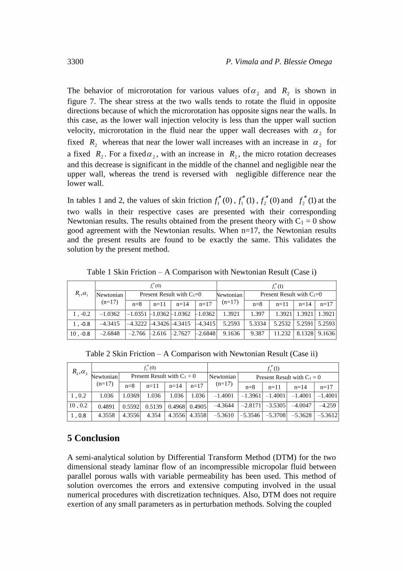
In tables 1 and 2, the values of skin friction 1 (0)f , 1 (1)f , 2 (0)f and 2 (1)f at the
two walls in their respective cases are presented with their corresponding
Newtonian results. The results obtained from the present theory with C1 = 0 show
good agreement with the Newtonian results. When n=17, the Newtonian results
and the present results are found to be exactly the same. This validates the
solution by the present method.
Table 1 Skin Friction – A Comparison with Newtonian Result (Case i)
1 1,R 1 (0)f
1 (1)f
Newtonian
(n=17)
Present Result with C1=0 Newtonian
(n=17)
Present Result with C1=0
n=8 n=11 n=14 n=17 n=8 n=11 n=14 n=17
1 , -0.2 –1.0362 –1.0351 –1.0362 –1.0362 –1.0362 1.3921 1.397 1.3921 1.3921 1.3921
1 , -0.8 –4.3415 –4.3222 –4.3426 –4.3415 –4.3415 5.2593 5.3334 5.2532 5.2591 5.2593
10 , -0.8 –2.6848 –2.766 –2.616 –2.7627 –2.6848 9.1636 9.387 11.232 8.1328 9.1636
Table 2 Skin Friction – A Comparison with Newtonian Result (Case ii)
2 2,R
2 (0)f 2 (1)f
Newtonian
(n=17)
Present Result with C1 = 0 Newtonian
(n=17) Present Result with C1 = 0
n=8 n=11 n=14 n=17 n=8 n=11 n=14 n=17
1 , 0.2 1.036 1.0369 1.036 1.036 1.036 –1.4001 –1.3961 –1.4001 –1.4001 –1.4001
10 , 0.2 0.4891 0.5592 0.5139 0.4968 0.4905 –4.3644 –2.8171 –3.5305 –4.0047 –4.259
1 , 0.8 4.3558 4.3556 4.354 4.3556 4.3558 –5.3610 –5.3546 –5.3708 –5.3628 –5.3612
5 Conclusion
A semi-analytical solution by Differential Transform Method (DTM) for the two
dimensional steady laminar flow of an incompressible micropolar fluid between
parallel porous walls with variable permeability has been used. This method of
solution overcomes the errors and extensive computing involved in the usual
numerical procedures with discretization techniques. Also, DTM does not require
exertion of any small parameters as in perturbation methods. Solving the coupled

Solution of micropolar fluid flow through porous channels 3301
set of non-linear partial differential equations is generally difficult. Hence, the
problem has been reduced to a system of non-linear ordinary differential
equations using Berman’s similarity transformation and the resulting problem has
been solved using DTM with ease. This semi-analytical DTM provides a simple
iterative method of solution for the problem. On the whole, this paper portrays the
efficiency of the DTM for solving such problems governed by highly non-linear
coupled set of partial differential equations by reducing to a system of ordinary
differential equations. However, it can also be solved using DTM in two
dimensions without reducing to ordinary differential equations. There is also
scope for solving the above problem using a multi-step DTM which gives a better
approximation than DTM.
References
[1] T. Ariman, M.A Turk, N.D Sylvester, Microcontinuum Fluid Mechanics-A
Review, Int.J.Engng Sci., 11(1973), 905-930.
http://dx.doi.org/10.1016/0020-7225(73)90038-4
[2] Aydin Kurnaz, Galip Oturanc, Mehmet E.Kiris, n-dimensional differential
transform method for solving PDEs, International Journal of Computer
Mathematics, 82(3) (2005), 369-380.
http://dx.doi.org/10.1080/0020716042000301725
[3] Berman, A.S., Laminar flow in channels with porous walls, Journal. of.
Applied. Physics, 24 (1953) 1232-1235. http://dx.doi.org/10.1063/1.1721476
[4] Charles W. Bert, Application of differential transform method to heat
conduction in tapered fins, Journal of Heat Transfer, 124 (2002), 208-209.
http://dx.doi.org/10.1115/1.1423316
[5] Chen, C. K., Ho, S. H., Solving partial differential equations by two
dimensional differential transform method, Applied Mathematics and
Computation, 106 (1999), 171-179.
http://dx.doi.org/10.1016/s0096-3003(98)10115-7
[6] A. C. Eringen, Simple Microfluids, Int.J.Eng. Sci., 2(1964), 205-217.
http://dx.doi.org/10.1016/0020-7225(64)90005-9
[7] A. C. Eringen, Theory of Micropolar fluids, Purdue University, Lafayette,
Indiana, 1965,1-35.
[8] N. A. Kelson, A. Desseaux, T.W Farrell, Micropolar flow in a porous
channel with high mass transfer, ANZIAM, 44(E) (2003), 479-495.

3302 P. Vimala and P. Blessie Omega
[9] Rashidi, M.M., Sadri, S.M., Solution of the laminar viscous flow in a
semi-porous channel in the presence of a uniform magnetic field by using the
differential transform method, Int. J. Contemp. Math. Sciences, 5 (15) (2010),
711-120.
[10] Rashidi, M.M., Mohimanian Pour, S.A., Laraqi, N., A semi-analytical
solution of Micropolar flow in a porous channel with mass injection by using
differential transform method, Nonlinear Analysis: Modeling and Control, 15 (3)
(2010), 341-350.
[11] Terrill, R.M., Shrestha, G.M., Laminar flow through parallel and
uniformly porous walls of different permeability, ZAMP, 16 (1965) 470-482.
http://dx.doi.org/10.1007/bf01593923
[12] Vimala, P., Blessie Omega, P., Laminar flow of a Newtonian fluid through
parallel porous walls-Solution by differential transform method, Proceedings of
the Fortieth National Conference on Fluid Mechanics and Fluid Power, (2013),
1549-1558.
[13] Xin-hui Si, Lian-cun Zheng, Xin-xin Zhang, Xin-yi Si, Flow of
Micropolar fluid between two orthogonally moving porous disks, Applied
Mathematics and Mechanics, 33 (8) (2012), 963-974.
http://dx.doi.org/10.1007/s10483-012-1598-8
[14] Xin-yi Si, Xin-hui Si, Lian-cun Zheng, Xin-xin Zhang, Homotopy analysis
solution for Micropolar fluid flow through porous channel with expanding or
contracting walls of different permeabilities, Applied Mathematics and
Mechanics, 32(7) (2011), 859-874.
http://dx.doi.org/10.1007/s10483-011-1465-6
[15] Yuan, S.W., Further investigation of laminar flow in channels with
porous walls, Journal of Applied Physics, 27 (1956) 267-269.
http://dx.doi.org/10.1063/1.1722355
[16] Zhou, J.K., Differential transformation and its application for electric circuit
analysis (in Chinese), Huazhong University Press, 1986.
Received: December 15, 2014; Published: April 20, 2015