Solution Methods for Nonlinear Finite Element Analysis (NFEA)
39
1 Solution Methods for Nonlinear Finite Element Analysis (NFEA) Kjell Magne Mathisen Department of Structural Engineering Norwegian University of Science and Technology Lecture 11: Geilo Winter School - January, 2012 Geilo 2012
Transcript of Solution Methods for Nonlinear Finite Element Analysis (NFEA)

1
Solution Methods for Nonlinear Finite Element Analysis (NFEA)
Kjell Magne MathisenDepartment of Structural Engineering
Norwegian University of Science and TechnologyLecture 11: Geilo Winter School - January, 2012
Geilo 2012

2
Outline• Linear versus nonlinear reponse
• Fundamental and secondary path
• Critical points
• Why Nonlinear Finite Element Analysis (NFEA) ?
• Sources of nonlinearities
• Solving nonlinear algebraic equations by Newton’s method
• Line search procedures and convergence criteria
• Arc-length methods
• Implicit dynamics
Geilo 2012

3
Linear vs Nonlinear Respons • Numerical simulation of the response where both the LHS and RHS depends
upon the primary unknown.
• Linear versus Nonlinear FEA: LFEA:
NFEA:
• Field of Nonlinear FEA: Continuum mechanics FE discretization (FEM) Numerical solution algorithms Software considerations (engineering)
Geilo 2012
K D R
( ) ( )K D D R D
• Requirements for an effective NFEA:
Interaction and mutual enrichment
Physical Mathematical insight formulation
Physical and theoreticalunderstanding is most important

4
Equilibrium path• The equilibrium path is a graphical representation
of the response (load-deflection) diagram that characterize the overall behaviour of the problem
• Each point on the equilibrium path represent a equilibrium point or equilibrium configuration
• The unstressed and undeformed configurationfrom which loads and deflection are measured is called the reference state
• The equilibrium path that crosses the reference state is called the fundamental (or primary) path
• Any equilibrium path that is not a fundamental path but connects with it at a critical point is called asecondary path
Geilo 2012

5
Critical points
• Limit points (L), are points on the equilibrium path at which the tangent is horizontal
• Bifurcation points (B), are points where two or more equilibrium paths cross
• Turning points (T), are points where the tangent is vertical
• Failure points (F), are points where the path suddenly stops because of physical failure
Geilo 2012
Snap through Snap back BifurcationBifurcation combined withlimit-points and snap-back

6
Advantages of linear response• A linear structure can sustain any load whatsoever and undergo any
displacement magnitude
• There are no critical (limit, bifurcation, turning or failure) points
• Solutions for various load cases may be superimposed
• Removing all loads returns the structure to the reference state
• Simple direct solution of the structural stiffness relationship without need for costly load incrementation and iterative schemes
Geilo 2012

7
Reasons for Nonlinear FEA• Strength analysis – how much load can the structure support before global failure
occurs
• Stability analysis – finding critical points (limit points and bifurcation points) closest to operational range
• Service configuration analysis – finding the ‘operational’ equilibrium configuration of certain slender structures when the fabrication and service configurations are quite different (e.g. cable and inflatable structures)
• Reserve strength analysis – finding the load carrying capacity beyond critical points to assess safety under abnormal conditions
• Progressive failure analysis – a combined strength and stability analysis in which progressive detoriation (e.g. cracking) is considered
Geilo 2012

8
Reasons for NFEA (2)• Establish the causes of a structural failure
• Safety and serviceability assessment of existing infrastructure whose integrity may be in doubt due to:
– Visible damage (cracking, etc)
– Special loadings not envisaged at the design state
– Health–monitoring
– Concern over corrosion or general aging
• A shift towards high performance materials and more efficient utilization of structural components
• Direct use of NFEA in design for both ultimate load and serviceability limit states
Geilo 2012

9
Reasons for NFEA (3)• Simulation of materials processing and manufacturing (e.g. metal forming,
extrusion and casting processes)
• In research:– To establish simple ‘code-based’ methods of analysis and design
– To understand basic structural behaviour
– To test the validity of proposed ‘material models’
• Computer hardware becomes cheaper and faster and FE software becomes more robust and user-friendly
• It will simply become easier for an engineer to apply direct analysis rather than code-based checking
Geilo 2012

10
Consequences of NFEA• For the analyst familiar with the use of LFEA, there are a number of consequences
of nonlinear behaviour that have to be recognized before embarking on a NFEA: The principle of superposition cannot be applied
Results of several ‘load cases’ cannot be scaled, factored and combined as is done with LFEA
Only one load case can be handled at a time
The loading history (i.e. sequence of application of loads) may be important
The structural response can be markedly non-proportional to the applied loading, even for simple loading states
Careful thought needs to be given to what is an appropriate measure of the behaviour
The initial state of stress (e.g. residual stresses from welding, temperature, or prestressing of reinforcement and cables) may be extremely important for the overall response
Geilo 2012

11
A typical Nonlinear Problem
Possible questions: Yield load Limit load Plastic zones Residual stresses Permanent deflections
Geilo 2012

12
Sources of Nonlinearities• Geometric Nonlinearity:
Physical source: Change in geometry as the structure deforms is taken into account in setting up the strain displacement (kinematic) and equilibrium equations.
Applications:– Slender structures– Tensile structures (cable structures and inflatable membranes) – Metal and plastic forming– Stability of all types of structures
Mathematical source:The strain-displacement operator is nonlinear when finite strains (as opposed to infinitesimal strains) are expressed in terms of displacements u
Considering geometric nonlinearities, the operator applied to the stresses, for linear elasticity, is not necessarily the transposed of the strain-displacement operator
Geilo 2012
ε u
T 0 b =

13
Example – Geometric Nonlin.• Snap-through behavior of a shallow
spherical cap with various ring loads
Geilo 2012
T

14
Sources of Nonlinearities (2)• Material Nonlinearity:
Physical source: Material behavior depends on current deformationstate and possibly past history of the deformation. The constitutive relation may depend on other variables (prestress, temperature, time, moisture, electromagnetic fields, etc)
Applications:– Nonlinear elasticity– Plasticity– Viscoelasticity– Creep, or inelastic rate effects
Mathematical source:The constitutive relation that relates strain and stresses, C, is nonlinear when the material no longer may be expressed in terms of e.g. Hooke’s generalized law:
Geilo 2012
0 C

15
Sources of Nonlinearities (3)• Force Boundary Condition Nonlinearity:
Physical source: Applied forces depend on the deformation.
Applications:– Hydrostatic loads (submerged tubular bridges)– Aerodynamic or hydrodynamic loads– Non-conservative follower forces
Mathematical source:The applied forces, prescribed surface tractions and/or body forces b, depend on the unknown displacements u:
Geilo 2012
( )( )
t t ub b u
t

16
Sources of Nonlinearities (4)• Displacement Boundary Condition Nonlinearity:
Physical source: Displacement boundary conditions depend on the deformation.
Applications:The most important application is the contact problem, in which no interpenetration conditions are enforced on flexible bodies while the extent of contact area is unknown.
Mathematical source:The prescribed displacements depend on unknown displacements, u:
Geilo 2012
( )u u u
u

17
Example ─ Geometric Nonlin.
• A two-element truss model with constant axial stiffness EA and initial axial force No is considered to illustrate some basic features of geometric nonlinear behavior.
• From the three fundamental laws: Compatibility Material law Equilibrium
Geilo 2012
3 2 2o3
o o
3 22EA u hP u hu h u N
(nonlinear load - displacement relationship)
2P
u
h
a a
o o o

18
Example ─ Geometric Nonlin.
• Equilibrium path representing the solution of the nonlinear load-displacement relationship As the load increases (downward) an initial maximum load, called the limit load, is reached
at the limit point (a) Further increase of the load would lead to snap-through to the new equilibrium state at (b).
The snap-through is an unstable dynamic process the straight line from (a) to (b) does not represent the true equilibrium path.
In order to trace the true unstable equilibrium branch between (a) and (b), the displacement u has to be prescribed rather than prescribing the load P.
Geilo 2012

19
Solving the Nonlinear Equations
Geilo 2012
• From conservation of linear momentum, we may establish the equations of motion.
• Substituting the FE approximations (and neglecting time dependent terms), the global equilibrium equations on discretized form is obtained:
ext int res ext int
externally nodal forcesapplied loads from internal
element stresses
ext int
R R R R R 0
R Rwhere and denote sum of externally applied loadsand sum of internal element nod
ext
1 1
int int
1 1
=
els els
i i
els els
i
N NT T
e ii i V S
N NT
ii i V
dV + dS
dV
R r P N N P
R r B
al forces, respectively :
b t

20
Solving the Nonlinear Equations
Geilo 2012
• In order to satisfy equilibrium, external and internal forces have to be in balance
• Consider the solution of nonlinear equilibrium equations for prescribed values of the load or time parameter .
• The problem consists of finding the displacement vector which produces an internal force vector
, balancing externally applied loads .
res ext int . R R R 0
intR extR
D
ext R

21
Load incrementation
Geilo 2012
• Our purpose is to trace the fundamental (primary) equilibrium path while travers-ing critical points (limit, turning and bifurcation points)
we want to calculate a seriesof solutions:
that within prescribed accuracy satisfy the equilibrium equations:
• A major problem in tracing a nonlinear solution path is how to choose the size of the load increments .
extR
1D 3D 4D
D
ext1R equilibrium path
2D
ext2R
ext3R
ext4R
turning point
limit point
step, 0,1,2, ,n n n = nD for
n
res ext int R R R 0

22
Incremental-Iterative solution
Geilo 2012
• By linearizing the residual of the global equilibrium equations the incremental form of the equations of motion expressed in terms of the incremental nodal displacements , is obtained as:
nD 1n 1D n 1D
0n 1R
extnR
0n 1D
extn 1R
extR
D
0n 1D
int,0n 1R
intnR
0n 1R
intn 1R
D
res1res res11 1
1
res1 1 1
res int ext
11 1 1
ii i i
nn nn
iiiT n n n
i i ii
T nn n n
RR R D 0D
K D R
R R RKD D D
where

23
Incremental-Iterative solution
Geilo 2012
• The most frequently used solution procedures for NFEA consists of a predictor step involving forward Euler load incrementation and a correc-tor step in which some kind of Newton iterations are used to enforce equilibrium.
• The incremental-iterative procedure that advances the solution while satisfying the global equilibrium equations at each iteration ‘i’, within each time (load) step ‘n+1’ , is governed by the incremental equations:
• A series of successive approximations gives: nD 1n 1D n 1D
0n 1R
extnR
0n 1D
extn 1R
extR
D
0n 1D
int,0n 1R
intnR
0n 1R
intn 1R
1
1 1 1
i i i
n n n
D D D
res1 1 1
iiiT n n n
K D R

24
Newton’s method
Geilo 2012
• Newton’s method is the most rapidly convergent process for solution of problems in which only one evaluation of the residual is made in each iteration.
• Indeed, it is the only method, provided that the initial solution is within the “ball of convergence”, in which the asymptotic rate of convergence is quadratic.
• Newton’s method illustrated in the Figure shows the very rapid convergence that can be achieved. nD
1n 1D n 1D
0n 1R
extnR
0n 1D
extn 1R
extR
D
0n 1D
int,0n 1R
intnR
0n 1R
intn 1R
25
Weaknesses of Newton’s method
Geilo 2012
• The standard (true) Newton’s method, although effective in most cases, is not necessarily the most economical solution method and does not always provide rapid and reliable convergence.
• Weaknesses of the method: Computational expense:
─ Tangent stiffness has to be computed and assembled at each iteration within each load step─ If a direct solver is employed KT also needs to be factored at each iteration within each load
step Increment size:
─ If the time stepping algorithm used is not robust (self-adaptive), a certain degree of trial and error may be required to determine the appropriate load increments
Divergence:─ If the equilibrium path include critical points negative load increments must be prescribed to
go beyond limit points─ If the load increments are too large such that the solution falls outside ‘‘the ball of
convergence’’ analysis may fail to converge

26
Modified Newton methods
Geilo 2012
• Modified Newton methods differ from the standard method in that the tangent stiffness KT is only updated occasionally.
• Initial stiffness method: Tangent stiffness KT updated only once The method may result in a slow rate of
convergence
• Modified Newton’s method: Tangent stiffness KT updated occasionally
(but not for every iteration) More rapid convergence than the initial
stiffness method (but not quadratic)
• Quasi (secant) Newton methods: The inverse of the tangent stiffness obtained
by a secant approximation rather than recomputing and factorizing KT at every iteration
Initial stiffness method
Modified Newton’s method

27
Line search procedures
Geilo 2012
• By line searches (LS) an optimal incremental step length is obtained by minimizing the residual in the direction of .
• LS can be particularly useful for problems involving rapid changes in tangent stiffness, such as in reinforced concrete analysis when concrete cracks or steel yields.
• LS not only accelerate the iterative process, they can provide convergence where none is obtainable without LS, especially if the predictor increment lies outside the ‘‘ball of convergence’’.
• LS is highly recommended and may be used in all type of Newton methods; standard, modified, and quasi Newton methods.
DR
s
opts
opt optD s D
resR

28
Convergence criteria
Geilo 2012
• A convergence criteria measures how well the obtained solution satisfies equilibrium.• In NFEA of the convergence criteria are usually based on some norm of the:
Displacements (total or incremental) Residuals Energy (product of residual and displacement)
• Although displacement based criteria seem to be the most natural choice they are not advisable in general as they can be misleadingly satisfied by a slow convergence rate.
• Residual based criteria are far more reliable as they check that equilibrium has been achieved within a specified tolerance in the current increment.
• Alternatively energy based criteria that use both displacements and residuals may be applied. However, energy criteria should not be used together with LS.
• In general NFEA it is recommended that a combination of the three criteria is applied.• The convergence criteria and tolerances must be carefully chosen so as to provide
accurate yet economical solutions. If the convergence criterion is too loose inaccurate results are obtained. If the convergence criterion is too tight too much effort spent in
obtaining unnecessary accuracy.
29
Choosing step length
Geilo 2012
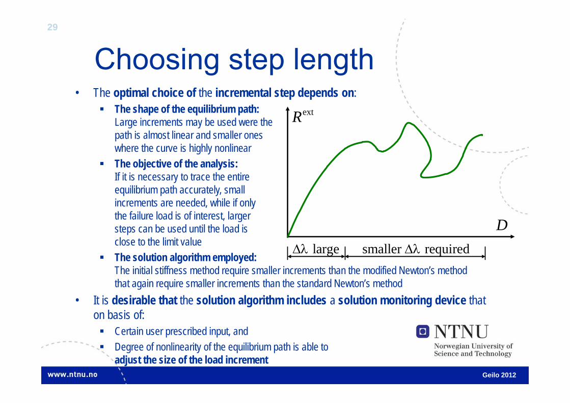
• The optimal choice of the incremental step depends on: The shape of the equilibrium path:
Large increments may be used were the path is almost linear and smaller ones where the curve is highly nonlinear
The objective of the analysis:If it is necessary to trace the entire equilibrium path accurately, small increments are needed, while if only the failure load is of interest, largersteps can be used until the load is close to the limit value
The solution algorithm employed: The initial stiffness method require smaller increments than the modified Newton’s method that again require smaller increments than the standard Newton’s method
• It is desirable that the solution algorithm includes a solution monitoring device that on basis of: Certain user prescribed input, and Degree of nonlinearity of the equilibrium path is able to
adjust the size of the load increment
extR
D large smaller required

30
Load incrementation
Geilo 2012
• For monotonic loading, the load increment can be based on number of iterations:
where is a ‘desired number of iterations’ selected by theanalyst, is the number of iterations required for convergence at increment ‘ 1’, while and are upper and lower limit of the increment prescribed by theanalyst
• However, the initial load increment still have to be selected by the analyst
min max1
1
dn n n
n
NN

31
Automatic load incrementation
Geilo 2012
• Even though you may find more sophisticated incremental load control methods, they can only work effectively if nonlinearity spreads gradually.
• Such methods cannot predict a sudden change in thestiffness.
• Solution methods based on prescribed loador prescribed displacements
are not able to trace the equilibrium pathbeyond limit and turning points, respectively.
ext ext ( )n n R R
( )n n D D
extR
1D 3D 4D
D
ext1R equilibrium path
2D
ext2R
ext3R
ext4R
load control
displacement control
displacement control fails
load control fails

32
Example ─ Load control fails
• At limit (L) and bifurcation (B) points the tangent stiffness KT becomes singular ⇒ the solution of the nonlinear equilibrium equations is not unique at this point
Geilo 2012

33
Example ─ Displ. control fails
• Cannot go beyond turning (T) points ⇒have to prescribe negative displacement increments
Geilo 2012
34
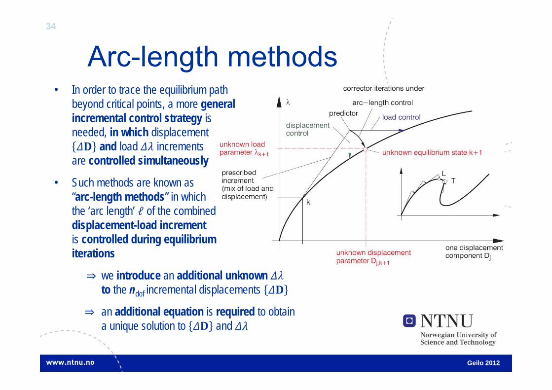
Arc-length methods• In order to trace the equilibrium path
beyond critical points, a more general incremental control strategy is needed, in which displacement
and load increments are controlled simultaneously
• Such methods are known as “arc-length methods” in which the ‘arc length’ ℓ of the combineddisplacement-load incrementis controlled during equilibrium iterations
⇒ we introduce an additional unknownto the ndof incremental displacements
⇒ an additional equation is required to obtain a unique solution to and
Geilo 2012

35
Arc-length methods (2)• In arc length methods a
constraint scalar equation is introduced
in which the ‘length’ ℓ ofthe combined displacement-load increment is prescribed
where is a scaling parameter( and have different dimension)
• The basic idea behind arc length methods is that instead of keeping the load (or the displacement) fixed during an incremental step, both the load and displacement increments are modified during iterations
⇒Limit and turning points may be passed with this method
Geilo 2012
( ) ( , ) 0T C Z C D
2 2 2T D D
36
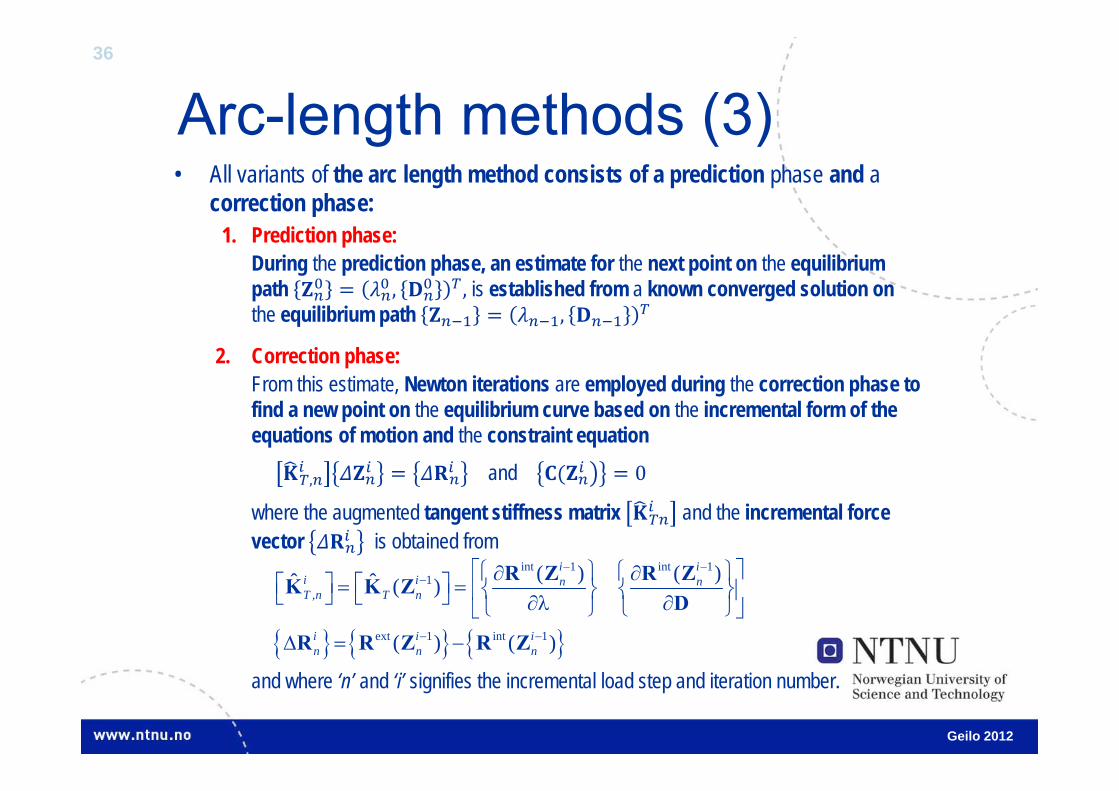
Arc-length methods (3)• All variants of the arc length method consists of a prediction phase and a
correction phase:1. Prediction phase:
During the prediction phase, an estimate for the next point on the equilibrium path , ,is established from a known converged solution onthe equilibrium path ,
2. Correction phase:From this estimate, Newton iterations are employed during the correction phase to find a new point on the equilibrium curve based on the incremental form of the equations of motion and the constraint equation
, and 0
where the augmented tangent stiffness matrix and the incremental force vector is obtained from
and where ‘n’ and ‘i’ signifies the incremental load step and iteration number.
Geilo 2012
int 1 int 11
,
ext 1 int 1
( ) ( )ˆ ˆ ( )
( ) ( )
i ii i n nT n T n
i i in n n
R Z R ZΚ Κ ZD
R R Z R Z

37
Arc-length methods (4)1. Normal plane arc-length method
Newton iterations are forced to follow a hyperplane that is normal to the initial tangent at a ‘distance’ ℓfrom the previous obtained solution at step ‘n-1’:
ℓ 0
2. Updated normal plane arc-length methodHyperplane is normal to the updated tangent instead of :
ℓ 0
3. Spherical arc-length methodNewton iterations are forced to follow a hypersphereof radius ℓcentered at the converged solutionof the previous step ‘n-1’:
ℓ 0
4. Cylindrical arc-length method
Geilo 2012
21 10 ( ) 0
Ti i in n n n n C D D D D D

38
Implicit dynamics algorithm
Geilo 2012
• The main advantage of an implicit method over an explicit method is the large time step permitted by unconditionally stable time integration methods
• However, unconditional stability in a linear problem does not guarantee unconditional stability in a nonlinear problem
• The incremental strategy for dynamic problems is provided by a temporal discretization algorithm that transforms the ordinary differential equation system into a time-stepping sequence of nonlinear algebraic equations.
• Hence, a unified treatment of nonlinear static and implicit dynamic algorithms may be employed:
⇒ The solution algorithms that have been presented for nonlinear static problems may also be applied to nonlinear dynamic problems

39
Implicit dynamics algorithm (2)
Geilo 2012
ext int
1 1 1T nn n n n M D C D K D R R
• Substituting a linearized (first-order) approximation to the internal forces , the equation of motion at time tn+1 becomes:
• Substituting the updated values for the nodal accelerations and velocities at time tn+1 , that with Newmark approximations may be obtained from:
we obtain the equation of motion on incremental form
where
2 11
11
1 1 12
1 12
n nn n n
n nn n n
tt
tt
D D D D D
D D D D D
eff eff
1n n K D R
eff2
eff ext int
1 1
1
1 1 1 + 1 12 2
T nn
n n n nn n n
xt t
tt
K M C K
R R R M D D C D D