
Solution Focus Area FIDO* Support on Intel® Platforms...New strong authentication standards from...
13
Abstract 63% of data breaches involve weak, default or stolen passwords, according to the Verizon Data Breach Report. Yet simple password match is still the dominant user authentication system. New strong authentication standards from the FIDO Alliance—combined with passwordless solutions from vendors—can simplify user experiences, build customer confidence and harden security defenses. Intel highly recommends that enterprises and service providers select platforms with restricted execution environment support, so as to build their security stacks on solid bedrock. This paper demonstrates the rigor of Intel’s security architecture, and describes in detail how it can be deployed to address one of cybersecurity’s biggest problems. 1 Introduction User authentication processes for Web access control are not only critical to cyber defense, but they also send key messages to customers about the trustworthiness of online environments. New strong, high-assurance authentication methods tell customers that site security is taken seriously. They can also provide simpler, easier access for customers, and stronger protection against bad actors trying to compromise overall system security. FIDO—for Fast Identity Online—is the industry standard for next-generation strong authentication. FIDO today supports an international ecosystem which enables enterprises and service providers to deploy strong authentication solutions that reduce reliance on passwords and provide superior protection against phishing and other cyberattacks. In strong FIDO-compliant authentication, user identity credentials are stored in the local device, not in an enterprise server. This offers many advantages in both cybersecurity and user experience—but only if each user’s device is itself strongly secured. The FIDO security requirements workgroup (SRWG) has defined four different FIDO security levels, ranging from level 1 to level 3+, 1 being the lowest. At security level one (SL1) a FIDO authenticator runs as an application inside a host OS. There are some best practices for SL1 host OS environment such as secure boot as explained later in the paper. But level one security may fall short of the high-assurance, strong authentication standard. A user platform vendor will typically target its platform to meet FIDO requirements at a specific security level. Intel, along with its ecosystem partners, offers a complete “level 2 or higher” strong authentication solution—with software, firmware, and hardware that anchors user authentication in the bedrock of Intel hardware security. FIDO SL2 can be supported on all FIDO-enabled platforms, such as personal computers, tablets, phones and, in standalone FIDO authenticators such as pluggable cameras or fingerprint sensors. Table of Contents 1 Introduction 1 2 ROE Support in Intel SOC 2 3 CSME 3 4 SGX 6 5 VT / VTd 8 6 Summary 12 7 Glossary 13 Author Nitin Sarangdhar [email protected] FIDO* Support on Intel® Platforms Industry Solution Focus Area WHITE PAPER
Transcript of Solution Focus Area FIDO* Support on Intel® Platforms...New strong authentication standards from...

Abstract63% of data breaches involve weak, default or stolen passwords, according to the Verizon Data Breach Report. Yet simple password match is still the dominant user authentication system. New strong authentication standards from the FIDO Alliance—combined with passwordless solutions from vendors—can simplify user experiences, build customer confidence and harden security defenses. Intel highly recommends that enterprises and service providers select platforms with restricted execution environment support, so as to build their security stacks on solid bedrock. This paper demonstrates the rigor of Intel’s security architecture, and describes in detail how it can be deployed to address one of cybersecurity’s biggest problems.
1 IntroductionUser authentication processes for Web access control are not only critical to cyber defense, but they also send key messages to customers about the trustworthiness of online environments. New strong, high-assurance authentication methods tell customers that site security is taken seriously. They can also provide simpler, easier access for customers, and stronger protection against bad actors trying to compromise overall system security.
FIDO—for Fast Identity Online—is the industry standard for next-generation strong authentication. FIDO today supports an international ecosystem which enables enterprises and service providers to deploy strong authentication solutions that reduce reliance on passwords and provide superior protection against phishing and other cyberattacks.
In strong FIDO-compliant authentication, user identity credentials are stored in the local device, not in an enterprise server. This offers many advantages in both cybersecurity and user experience—but only if each user’s device is itself strongly secured. The FIDO security requirements workgroup (SRWG) has defined four different FIDO security levels, ranging from level 1 to level 3+, 1 being the lowest. At security level one (SL1) a FIDO authenticator runs as an application inside a host OS. There are some best practices for SL1 host OS environment such as secure boot as explained later in the paper. But level one security may fall short of the high-assurance, strong authentication standard.
A user platform vendor will typically target its platform to meet FIDO requirements at a specific security level. Intel, along with its ecosystem partners, offers a complete “level 2 or higher” strong authentication solution—with software, firmware, and hardware that anchors user authentication in the bedrock of Intel hardware security. FIDO SL2 can be supported on all FIDO-enabled platforms, such as personal computers, tablets, phones and, in standalone FIDO authenticators such as pluggable cameras or fingerprint sensors.
Table of Contents
1 Introduction . . . . . . . . . . . . . . . . . . . 1
2 ROE Support in Intel SOC . . . . . . 2
3 CSME . . . . . . . . . . . . . . . . . . . . . . . . . 3
4 SGX . . . . . . . . . . . . . . . . . . . . . . . . . . 6
5 VT / VTd . . . . . . . . . . . . . . . . . . . . . . 8
6 Summary . . . . . . . . . . . . . . . . . . . . . 12
7 Glossary . . . . . . . . . . . . . . . . . . . . . 13
Author
Nitin [email protected]
FIDO* Support on Intel® Platforms
IndustrySolution Focus Area
white paper

2
When the relying party in an online transaction (such as a bank or hospital) uses only a simple username/password match, it opens the door to increased fraud attacks on customer accounts. To thwart such attacks, in the FIDO strong authentication model, the weak password is augmented with a second factor that as a minimum confirms user presence or a single first factor that verifies the unique user. The FIDO authentication factor is based on PKI, public key infrastructure.
During the registration process, a platform unique public / private key pair is generated by the authenticator. The private key is stored securely inside the authenticator. The public key is signed with a device model specific attestation key. The attestation key allows the relying party to verify the security level supported by the platform. Relying parties are thus able to perform a risk assessment with the aid of the FIDO assertion key provided by the platform. Using this risk assessment, relying parties may choose to deny requested service to a platform with known security vulnerabilities, or introduce additional friction, such as the use of an out-of-band non-FIDO factor, to get that platform to an acceptable assurance level.
During authentication, the FIDO assertion is signed using the unique private key bound to the authenticator. The relying parties are thus able to use the fresh FIDO assertion to verify the user identity or at a minimum user presence based on the type of authenticator supported on the platform. This approach eliminates a whole class of attacks commonly found with password-based systems. The most common being the dictionary attack associated with guessing user passwords, and phishing attacks where the user willingly discloses a shared password. Credential-stuffing attacks, often enabled by botnets, are also defeated by the use of these PKI assertions. Intel’s SL2 or higher authentication and access controls, when properly implemented and maintained, offers both relying parties and end users strong protection against these types of attacks.
Though simple password match systems are now widely regarded as inherently broken, they do have one valuable feature: passwords can be changed if the user believes that they have been stolen. This is not true for user biometric factors such as face or speech recognition, or fingerprints. Thus even FIDO SL1 biometric authentication platforms can be vulnerable to biometric replay attacks (unauthorized re-use of stolen biometric credentials). It is essential for FIDO high-assurance authentication, therefore, that user biometrics are properly protected from a replay attack on the platform. To do that, FIDO SL2 mandates that authenticators implement a special Restricted Operating Environment, or ROE, to protect biometric data and authentication credentials against operating system compromises—the kind that can result from app downloads, malicious content and similar threats.
FIDO security level 2 and above requirements can be met with a FIDO authenticator running as a Trusted Application (TA) inside a Restricted Operating Environment (ROE). Creating an ROE and a TA requires additional platform hardware, firmware and software support from the platform OEM. The TA must also be able to provide proper attestation to the relying party during the registration process. In other words, the device must prove to the relying party that it can
be trusted, so that the identity assertions of the user are in fact reliable. Each FIDO-compliant user device has its own attestation key pair. These keys (and their related certificates) prevent attackers from swapping their bad public keys for the user’s good keys since the bad guys’ keys lack the proper certification.
Another important consideration for FIDO is the life-cycle management of all the ROE security ingredients. Cyber controls can never be static, and FIDO’s security requirements are enhanced on an ongoing basis to address emerging new threats. FIDO establishes a revocation timeline for certified FIDO platforms whenever a new platform vulnerability is identified. Unless this vulnerability is resolved promptly, that platform’s certification is revoked.
The FIDO Alliance has created specifications and certifications that enable the world’s largest interoperable ecosystem of hardware-, mobile- and biometrics-based authenticators. Intel’s hardware architecture supports strong FIDO-compliant authentication, by providing a solid cryptographic foundation and an enhanced hardware security architecture. This architecture is broadly adopted around the world, which helps support trusted interoperability. It also enables the flexible and concurrent allocation of compute resources for purposes of internal FIDO SL2 authentication processing. This makes user authentication processes as quick and efficient as if implemented in the host OS, but much stronger cryptographically.
This paper intends to give a detailed overview of the ROE component, security architecture and lifecycle management support available inside Intel SOCs. Intel highly recommends targeting platforms for FIDO SL2 or higher to eliminate attacks that can be easily mounted from the host OS (e.g., when users unknowingly download malicious content).
Note: Besides using features inside the Intel SOC as explained in this paper, platform OEMs must provide compatible biometric hardware, firmware, software and lifecycle management support to provide a complete FIDO L2 or above platform solution.
2 ROE support in Intel SOCIn order for a platform to achieve FIDO certification at SL2 or higher, certain Restricted Operating Environments, or ROEs, are required to protect authentication credentials.
Intel SOCs support three potential ROE environments that can be used to enable a FIDO SL2 and above Authenticator. This section provides a high-level overview of each such ROEs. Additional details specific to each ROE and their use to build a FIDO Authenticator is provided in subsequent sections.
• CSME/TXE: Converged Security and Manageability Engine or Trusted Execution Engine (CSME) is a separate security microcontroller in Intel silicon with dedicated memory and IO support. This subsystem is isolated from the application processor running the operating system. The operating system software communicates with applications running on CSME through a set of well-defined interfaces. CSME firmware provides the necessary foundation to build a FIDO authenticator TA.
White Paper | FIDO Support

3
White Paper | FIDO Support
• SGX: Intel® Software Guard Extensions (Intel® SGX) are a set of CPU instructions that applications can use to protect selected code and data from disclosure or modification. Developers can partition their application into CPU-hardened “enclaves” or protected areas of execution in memory that provide enhanced security on a platform, even if the host OS is compromised. These enclaves interface with a normal host OS application through developer defined custom software interface. SGX based enclaves provide the necessary foundation to build a FIDO Authenticator TA.
• VT/VTd: VT (Virtualization Technology)/ VTd (Virtualization Technology for devices) hardware allows the creation of one or more secure virtual machines that can be completely isolated from the host OS which also runs as a virtual machine. The complete solution requires a hypervisor that restricts access to specific IO and memory address spaces from the host OS. A TA running inside a secure VM provides the necessary foundation to build a FIDO Authenticator. This environment also provides a high degree of flexibility to support many different types of biometric hardware supported in the host OS environment.
3 CSME 3 .1 CSME Hardware
The hardware architecture is illustrated in Figure 1.
CSME hardware is comprised of a processor, code and data caches, DMA (direct memory access) engines, cryptography
engines, read-only memory (ROM), internal memory (static random-access memory, or SRAM), a timer, and other supporting devices. The devices are connected through an internal bus that is not exposed to the main application processor subsystem. This enables independence, isolation, and enhanced the security of the engine. The management engine’s hardware devices are only accessible by the processor, the DMA engines, and the cryptography engine.
There is a small code and data cache to help the processor reduce the number of accesses to the internal SRAM. The internal SRAM is the memory that stores runtime firmware code and data. The capacity of SRAM varies depending on the product but generally ranges between 256KB and 1MB.
In addition to the internal SRAM, the management engine also uses a certain amount of DRAM (dynamic random-access memory) from the main system memory. Code and data pages that are not recently accessed may be evicted from the SRAM and swapped out to the reserved memory. When a page is needed again, it is swapped into the SRAM. During the boot process, the DRAM region that is by the management engine is reserved by the BIOS (basic input/output system) for the engine’s dedicated access. Pages stored in the DRAM are always integrity protected by the management engine and verified before their use in SRAM. The size of the reserved memory varies from product to product, but usually in the range between 4MB and 32MB. This is only a small fraction of the DRAM installed on today’s computing devices, and hence the impact to the main operating system performance is negligible.
For many embedded applications, it is necessary to transmit bulk data between the embedded memory and the host memory. The engine’s processor cannot address the host memory. Therefore, dedicated DMA engines are introduced for moving data between the engine’s memory and the main system’s memory. When addressing the host memory, the DMA engines use physical addresses. The DMA engines can only be programmed by the embedded firmware running on the management engine. The DMA engines can also be used to move a large amount of data between two buffers of the engine’s internal memory.
The cryptography engine offloads and accelerates heavily-used cryptography algorithms so those resource-consuming operations can be performed faster and they do not occupy the management engine’s processing bandwidth. The algorithms implemented by the cryptography engine include AES (Advanced Encryption Standard), SHA (Secure Hashing Algorithm), DRNG (Deterministic Random Number Generator) and big integer arithmetic. The cryptography engine is only accessible by the engine’s firmware. It is not directly available to the host, although some embedded applications implement and expose external interfaces for the host applications to take advantage of the cryptography engine. The cryptography driver in the firmware kernel not only abstracts interfaces for the cryptography engine hardware, but also implements other cryptography algorithms that are not available in the hardware.
There are three master devices—processor, DMA, and cryptography engine—on the management engine. They all can access the embedded memory and process data. These devices operate concurrently, as long as the assets (for example, memory and global variables) that are being accessed by more than one device are properly protected against race conditions. The protection is usually realized by employing semaphores or mutexes. By commanding multiple devices to work simultaneously, firmware applications can be optimized to minimize the system resource idle time and boost performance. The mechanism implemented by the security and management engine is de facto equivalent to overlapped I/O (input/output) or asynchronous I/O for traditional operating systems. The security and management engine, the processor, the DMA engines, and the cryptography engine all operate at the same speed. The exact frequency varies among different products.
Figure 1 . Hardware architecture of the management engine
Code Cache
Data Cache
CryptographyEngine
DMA Engine
Host EndpointControllerInterface
Internal SRAM
ROM
I/O
MemoryControllers
Inte
rnal
Bus
Processor(Management Engine)
InterruptController
High Precisionand Watchdog
Timer
4
White Paper | FIDO Support
3 .2 CSME Firmware
Intel CSME uses a typical embedded system architecture, which consists of a boot ROM and updatable firmware. The boot ROM is immutable hardware and cannot be patched. The firmware, in its compressed form, is stored in NVRAM as part of the system firmware. Other system firmware includes BIOS, uCode patch, ACM (Authenticated Code Module), etc. The Intel CSME firmware utilizes Huffman compression and LZMA compression to conserve NVRAM.
During system boot, the boot ROM invokes DMA to bring Intel CSME binary image into internal SRAM and performs verification. The dictionary of Huffman compression is built in the controller of the NVRAM and decompression is conducted by the controller. In contrast, the LZMA decompression is performed by the loader process in firmware. The compressed firmware image is digitally signed by Intel with standard RSA (Rivest-Shamir-Adleman) and SHA (Secure Hash Algorithm). The public key hash is hardcoded in the boot ROM. The public key and signature are part of the firmware manifest. For some SKUs, the OEM cosigns the firmware with Intel, in which case two public keys and two signatures are present in the image.
Another important security task of the boot ROM is to read security fuses and derive keys from them. The security fuses that serve as the basis of key derivations are locked down immediately after being read by ROM. The lockdown essentially makes sure that Intel CSME firmware cannot access these fuses, and firmware recovery based on the fuses is possible in case of vulnerability. Once initialization is completed, and the signature on the firmware is verified, the boot ROM passes control to the first firmware process, ROM patch. The boot ROM records boot process information into the Intel CSME SRAM for later use by later stage firmware.
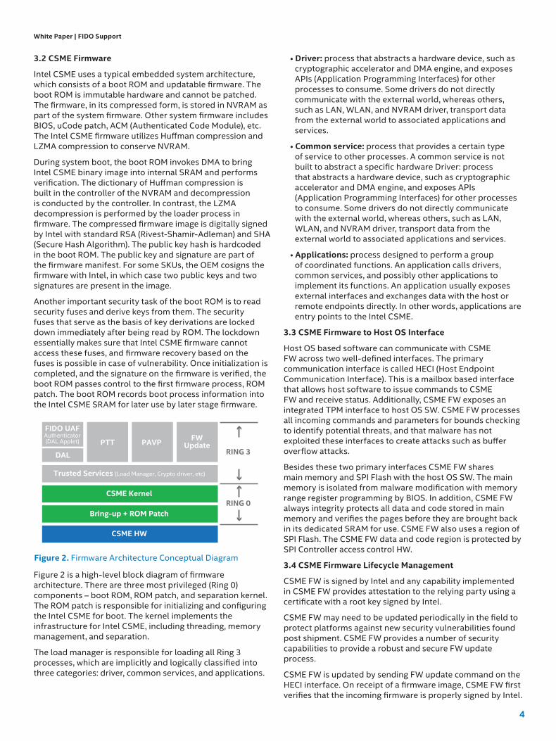
Figure 2 is a high-level block diagram of firmware architecture. There are three most privileged (Ring 0) components – boot ROM, ROM patch, and separation kernel. The ROM patch is responsible for initializing and configuring the Intel CSME for boot. The kernel implements the infrastructure for Intel CSME, including threading, memory management, and separation.
The load manager is responsible for loading all Ring 3 processes, which are implicitly and logically classified into three categories: driver, common services, and applications.
• Driver: process that abstracts a hardware device, such as cryptographic accelerator and DMA engine, and exposes APIs (Application Programming Interfaces) for other processes to consume. Some drivers do not directly communicate with the external world, whereas others, such as LAN, WLAN, and NVRAM driver, transport data from the external world to associated applications and services.
• Common service: process that provides a certain type of service to other processes. A common service is not built to abstract a specific hardware Driver: process that abstracts a hardware device, such as cryptographic accelerator and DMA engine, and exposes APIs (Application Programming Interfaces) for other processes to consume. Some drivers do not directly communicate with the external world, whereas others, such as LAN, WLAN, and NVRAM driver, transport data from the external world to associated applications and services.
• Applications: process designed to perform a group of coordinated functions. An application calls drivers, common services, and possibly other applications to implement its functions. An application usually exposes external interfaces and exchanges data with the host or remote endpoints directly. In other words, applications are entry points to the Intel CSME.
3 .3 CSME Firmware to Host OS Interface
Host OS based software can communicate with CSME FW across two well-defined interfaces. The primary communication interface is called HECI (Host Endpoint Communication Interface). This is a mailbox based interface that allows host software to issue commands to CSME FW and receive status. Additionally, CSME FW exposes an integrated TPM interface to host OS SW. CSME FW processes all incoming commands and parameters for bounds checking to identify potential threats, and that malware has not exploited these interfaces to create attacks such as buffer overflow attacks.
Besides these two primary interfaces CSME FW shares main memory and SPI Flash with the host OS SW. The main memory is isolated from malware modification with memory range register programming by BIOS. In addition, CSME FW always integrity protects all data and code stored in main memory and verifies the pages before they are brought back in its dedicated SRAM for use. CSME FW also uses a region of SPI Flash. The CSME FW data and code region is protected by SPI Controller access control HW.
3 .4 CSME Firmware Lifecycle Management
CSME FW is signed by Intel and any capability implemented in CSME FW provides attestation to the relying party using a certificate with a root key signed by Intel.
CSME FW may need to be updated periodically in the field to protect platforms against new security vulnerabilities found post shipment. CSME FW provides a number of security capabilities to provide a robust and secure FW update process.
CSME FW is updated by sending FW update command on the HECI interface. On receipt of a firmware image, CSME FW first verifies that the incoming firmware is properly signed by Intel.
CSME HW
Bring-up + ROM Patch
CSME Kernel
Trusted Services (Load Manager, Crypto driver, etc)
FIDO UAFAuthenticator(DAL Applet)
RING 3
RING 0
DAL
PTT FWUpdatePAVP
Figure 2 . Firmware Architecture Conceptual Diagram

5
White Paper | FIDO Support
The verification public key is provisioned inside CSME FW accessible secure storage.
CSME FW also provides a power glitch-resistant FW update interface. During FW update, CSME FW creates a recovery image of the current FW on the SPI flash and then starts the primary image FW update. If the update is successful, it applies a reset. On the next reboot, the ROM based CSME FW image verifies the updated primary image before using it. If the FW image signature verification does not successfully complete it automatically reverts to the recovery image and repeats the FW update process until it is successfully complete.
A fingerprint sensor FW update is managed by secure FW update process supported by the fingerprint sensor. This requires the fingerprint sensor to verify that firmware is properly signed by the IHV.
3 .5 CSME based FIDO support use cases
3 .5 .1 CSME based FIDO U2F Authenticator
Figure 3 above provides an example CSME based FIDO authenticator that relies upon a match on the sensor, The CSME FW application is responsible for generating FIDO assertions that are passed through an untrusted channel (UAF interface app in the host OS) to a FIDO1 / UAF based relying party.
3 .5 .2 CSME based FIDO U2F Authenticator
UAFInterface
App
FIDO 1UAFRP
FIDO U2FAuthenticator(DAL Applet)
DAL
CSMEKernal
CSME, PAVPHW
ProtectedDISPLAY
CSME FW
CSMEBackendServer
CSME BASE FIDO U2F AUTHENTICATOR
Display
• Shows an OK button in a random location using protected display.
CSME FW U2F Authenticator
• Generates random placement of the OK button. • Compares location of user mouse click to generate a match result
DAL
• CSME FW app that supports application applets
CSME Kernel
• Privileged CSME FW
CSME, PAVP HW
• HW subsystem
CSME Backend Server
• A backend server which provides security lifecycle management services to CSME FW.
Figure 4 . CSME based FIDO U2F Authenticator
UAFInterface
App
FIDO 1UAFRP
FIDO UAFAuthenticator(DAL Applet)
DAL
CSMEKernal
CSME, Sensor
ControllerHW
CSME FW
CSMEBackendServer
IHV Finger PrintMatch Sensor
CSME BASE FIDO UAF AUTHENTICATOR
IHV Finger Print Match Sensor • Provisioned with a signing key that delivers signed match results to
CSME FW
• Supports secure FW update by performing incoming FW image verification before applying FW update
CSME FW Authenticator • Receives signed match results from FPS • Generates a FIDO assertion
DAL • CSME FW app that supports application applets
CSME Kernel • Privileged CSME FW
CSME, Sensor Controller HW • HW subsystem
CSME Backend Server • A backend server which provides security lifecycle management
services to CSME FW
Figure 3 . CSME based FIDO U2F Authenticator

6
4 SGX4 .1 SGX Overview
Intel SGX is a hardware-assisted restricted operating environment with the attack surface limited to the CPU boundary. Intel SGX delivers 17 new Intel® architecture instructions that can be used by applications to set aside private regions of code and data, and can prevent direct attacks on executing code or data stored in memory. The applications are called enclaves.
SGX based enclaves receive confidentiality and integrity protection from malware present in a compromised OS, BIOS, VMM, or SMM software subsystem. SGX enclaves provide remote attestation and can be provisioned from an external server. A relying party can verify an application enclave’s identity and securely provision keys, credentials, and other sensitive data to the enclave.
The CPU boundary becomes the attack surface perimeter —all data, memory, and I/O outside this perimeter is encrypted using an encryption key unique to each individual enclave and is protected completely inside the enclave.
White Paper | FIDO Support
Figure 4 shows a CSME based FIDO U2F authenticator that relies on user selection of a randomized OK button on a protected display. The CSME FW application is responsible for generating FIDO assertions that are passed through an untrusted channel (UAF interface app in the host OS) to a FIDO1 / UAF based relying party.
3 .5 .3 CSME based Integrated TPM
CSME hosts integrated TPM which provides measured boot and other crypto services to a VT/VTd based FIDO authenticator as explained in subsequent sections. Integrated TPM can also be used by the host OS-based FIDO authenticator platform to provide a secure key storage.
The host CPU software communicates with the integrated TPM across a standard memory mapped IO interface exposing mailbox interface as defined by the TCG integrated TPM interface.
As described in the figure the TPM is used as a component to enforce the secure boot policy of the software subsystem running on the Application Processor. (AP). This software may consist of host OS-based FIDO Authenticator for FIDO security Level 1 targeted platforms or secure VM based FIDO Authenticator for FIDO security Level 2 targetted platforms.
Skylake (First SGX-compatible CPU)
App App
BADCODEBAD
Secret
Hacker
VULNERABILITY
Malware
ATTACK
Figure 6 . CSME based FIDO U2F Authenticator
AP SWSubsystem
SecureBoot
Attestation
CSMEKernal
CSME HW
CSME FW
CSMEBackendServer
TPM
CSME BASED INTEGRATED TPM
CSME FW Integrated TPM • Runs as an application • Seals encryption key for AP SW Subsystem • Unseals encryption key for AP SW Subsystem based on secure boot
measurements CSME Kernel • Privileged CSME FWCSME, TPM Interface • HW subsystemCSME Backend Server • A backend server which provides security lifecycle management
services to CSME FW. SOC SW • Uses unsealed encryption key for protecting secrets
Figure 5 . CSME based FIDO U2F Authenticator

7
White Paper | FIDO Support
4 .2 Developing Intel SGX Protected Applications
In Figure 7, a closer look at the design pattern reveals that an Intel SGX application consists of two parts: untrusted code and a trusted enclave that it securely calls into. A developer can create one-to-many trusted enclaves that work together to support distributed architectures. Common uses include key material, proprietary algorithms, biometric data, and CSR generation.
At runtime (see Figure 8 below), the Intel SGX instructions build and execute the enclave into a specially protected memory region with a restricted entry and exit location, which is defined by the developer. This prevents data leakage. Enclave code and data inside the CPU perimeter runs in the clear and enclave data written to disk is encrypted and checked for integrity.
4 .3 Attesting Enclaves and Sealing Data
OEMs (original equipment manufacturers) and ISVs (independent software vendors) commonly provision application software and secrets at the time of manufacturing or by complex field configurations that cannot cryptographically prove application integrity. Intel SGX enables local attestation between enclaves or remote attestation by a third party to verify that the application has not been compromised.
The protected portion of an application is loaded into an enclave where its code and data are measured. A report is sent to the remote application owner’s server, which in turn can validate that the enclave report was generated by an authentic Intel processor. Upon verification of the enclave identity, the remote party can verify the enclave and provision keys, credentials, or data.
Intel SGX includes an instruction for generating a CPU and enclave-specific "sealing key” that can be used to enhance storage security and retrieve sensitive information that may need to be stored to disk.
4 .4 Security Lifecycle management considerations
There are three potential security lifecycle events associated with an SGX based authenticator platform.
A fingerprint sensor FW update is managed by secure FW update process supported by the fingerprint sensor. This requires the fingerprint sensor to verify that firmware is properly signed by the IHV.
An SGX enclave software update is managed by each enclave communicating with the backend SGX server on a periodic basis to receive the latest update. A non-updated SGX enclave can be discovered by the relying party due to an expired certificate.
The SGX instructions are implemented in microcode, and any vulnerability updates in Intel microcode is delivered as a BIOS firmware update to the platform. BIOS is resident in SPI Flash part. The SPI controller provides necessary hardware support to make support during BIOS updates; a backup copy is maintained and available for recovery in case the update does not complete successfully.
Privileged System CodeOS, VMM, BIOS, SMM, ...
Application
UntrustedPart of App
CreateEnclave
Call Trusted()Cont.
ProcessSecrets
Return
TrustedPart of App
2
3
6
4
5
1
1) App built with trusted and untrusted parts2) App runs & creates the enclave which is placed in trusted memory3) Trusted function is called, execution transitioned to the enclave4) Enclave sees all process data in clear; external access to enclave data is denied5) Trusted function returns; enclave data remains in trusted memory6) Application continures normal executionNo unauthorized access or memory snooping of the enclave is possible. (See Figure 4.)
Figure legend:
1. App built with trusted and untrusted parts2. App runs and creates the enclave, which is placed in
trusted memory3. Trusted function is called, execution transitioned to
the enclave4. Enclave sees all process data in clear; external access
to enclave data is denied5. Trusted function returns enclave data6. Application continues normal execution
No unauthorized access or memory snooping of the enclave is possible. (See Figure 4.)
Figure 8 . SGX Runtime Execution
Figure 9 . Security Perimeter
Cores
CacheSSN:
111-00-1010
System Memory
CPU PACKAGE
Jco3lks937weu0cw
ejpoi
Snoop
Snoop
Memory Bus
Figure 7 . SGX Application Partitioning
SGX Application
UntrustedComponent
(Application)
Trusted Component(Enclave)
Data Code

8
White Paper | FIDO Support
4 .5 SGX Enabled FIDO Authenticator
A FIDO Authenticator can be built using SGX technology. An actual implementation of an SGX based authenticator in a shipping Intel SOC-based platform is shown in the figure below.
RING 3
VMO VM1
Host OS
Trusted Apps
Secure Kernel
VMO VMCS VMO1 VMCS
EPTO EPT1
VT-x2, VT-d
HOST OS SECURE VM
RING 0
RING 3
RING 0
HYPERVISOR
MEMORY
VIRTUALIZATION ARCHITECTURE OVERVIEW
BIOS • Enables VT/VTd HW • Identifies secure IO Controllers in the platformHypervisor • Programs EPT tables to ensure VM0 based SW cannot access
VM1 memory. • Programs VTd tables to ensure IO controllers assigned to VM0
based drivers cannot access VM1 memory. • Programs VT/VTd tables to provide services requested by
secure kernel. Secure Kernel • Enforces memory isolation between different Trusted
Application processes. • Enforces secure IO controller access to a single Trusted
Application driver in VM1. • Request hypervisor services for EPT/VTd buffer allocation as
required by Trusted application services. Trusted Applications/Drivers • Trusted drivers are responsible for management/programming of a secure IO controller hosting secure devices. • Trusted applications are responsible for miscellaneouS security services.
Figure 11 . Virtualization Architecture Overview
The enhanced security of the solution is based upon SGX enclave’s ability to be able to create a protected communication channel between different SGX enclaves with a shared key and to an external entity capable of communicating through a protected channel with a shared key.
The solution requires an IHV Finger Print Sensor capable of encrypting data using a secret encryption key provisioned by the IHV match enclave as part of enclave initialization. The solution also requires a FIDO relying party to receive and parse Intel Enclave IOC assertion to confirm the presence of a FIDO authenticator based on Intel SGX technology.
5 VT/VTd 5 .1 VT/VTd Architecture Overview
UAFInterface
App
FIDO 1UAFRP
Intel®Enclave
(IOC)
IHVMatch
Enclave
Intel SGX,Sensor
ControllerHardware
Intel® SGX
Intel SGXAttestation
Server
IHV Finger Print Sensor
INTEL SGX BASED FIDO AUTHENTICATOR
IHV Finger Print Sensor • Provisioned with an encryption key during manufacturing using IHV enclave • Delivers encrypted data to IHV enclave • Supports secure FW update by performing incoming FW image
verification before applying FW update IHV Match Enclave • Receives encrypted data from FPS • Executes match operation • Delivers results to Intel IOC enclaveIntel IOC enclave • Receives match results from IHV Match Enclave • Supports FIDO UAF protocol and delivers FIDO assertion to the FIDO RP using
a properly protected private key.SGX Attestation Server • A backend server which provides a certificate to IOC generated private keys
Figure 10 . SGX based FIDO Authenticator

9
White Paper | FIDO Support
Virtualization hardware (VT and VT-d) which has been in existence for some time on Intel SOC. VT hardware provides memory space Read/Write/Execute access control as defined by Extended Memory Page Tables programmed by the hypervisor. Extended Page Tables translate Guest Physical Addresses generated by a guest virtual machine to Host Physical Address space for the memory controller. Thus in a system containing a host OS VM and a secure VM, the EPT programming can be done such that a host OS VM generated accesses do not have permission to access memory space hosting the secure VM. Typically the secure VM can access some shared buffers in the host OS memory space to successfully receive commands/data and transmit status/data from host OS interfaces. VT hardware is also used for MMIO page access control from different VMs to require that a specific IO Controller can only be accessed from a specific VM.
VTd hardware support consists of ensuring DMA memory space access control as defined by the VTd Page Tables programmed by the hypervisor. The hypervisor defines DMA read / DMA write protection to main memory address spaces for different IO Controllers based on their PCI Bus Device Function Identifier. VTd hardware is used to verify that data buffers assigned to secure IO Controllers (managed by secure VM) cannot be read or written to using other non-secure IO Controllers (managed by host OS.)
Figure 11 provides an architecture overview of different hardware and software components to support a restricted operating environment using VT/VTd.
5 .2 Secure Boot
In order to meet the security goals of secure VM as a valid ROE, all software components in the VT-based platform must support secure boot. The basis of secure boot is a hardware root of trust that runs the first software component after reset. All subsequent software component are verified by the previous software component before being launched.
Immediately after reset, the BIOS typically resident in an SPI Flash, is the first component that runs. In this model, SPI Flash resident code acts as a hardware root of trust. To protect against SPI Flash-based reset vector modification attacks, a startup ACM which is signed by Intel can be enabled by BIOS. With this enhancement, the BIOS signing key is first verified against the fuses inside Intel SOC HW. BIOS measures and launches the hypervisor. The hypervisor programs the EPT tables to create memory space isolation for different VMs and launches the secure VM, followed by the host OS. BIOS may also communicate the presence of secure IO Controllers via SDEV ACPI table. If present the secure VM secures access to the IO controller access MMIO space to its own use and makes it non-accessible by the host OS VM. In addition, as the different drivers and applications are launched in the host OS and the secure VM, the access control to the secure IO controllers is transferred to the secure driver running inside the secure VM.
It is necessary that on every platform boot, the boot order is maintained to meet the security properties of the restricted execution environment. Thus on every boot, each software
component extends its measurements to the TPM. The TPM is used to seal a root key to specific PCR measurements. This TPM unseals the root key only if it receives the same PCR measurements, thus, in turn, confirming that the same boot component order was maintained and not tampered.
5 .3 Security Lifecycle management considerations .
There are potential security lifecycle events associated with an authenticator described above.
A fingerprint or camera sensor FW update is managed by secure FW update process supported by the sensor vendor. This requires the fingerprint sensor to verify that firmware is properly signed by the IHV.
Optionally the sensor vendor may rely upon the ability of secure VM to manage the sensor FW update. The sensor needs to have an ability to provide the hash of the current firmware on the sensor and an ability to block future updates. This would allow the secure VM to first verify the FW update and second lock it down after comparing it to the expected gold value.
A MIPI based camera does not contain any upgradeable FW on the device.
The Intel ISP FW is field upgradeable and is maintained and updated in the system by Intel as part of the secure driver update.
A vulnerability in VT/VTd hardware may require a microcode update. A vulnerability in ACM module may require an ACM module update. Intel maintains these modules and delivered to the OEM if an update is required.
A vulnerability in rest of the BIOS (if part of the TCB) may also be required. Intel provides various reference BIOS components to the OEM.
A vulnerability in the secure VM subsystem or various trusted application may require an update from the owner of the corresponding software module.
Since secure VM relies upon a TPM for its root of trust, any security vulnerability in the TPM would need to be updated by the TPM vendor. Intel maintains the integrated TPM. Ultimately platform OEM is responsible for ensuring that the all updated firmware components are delivered on the platform. If the platform contains a component with known vulnerability, it would need to be detected by the TA and reflected through certificate expiry of FIDO registration.
5 .4 VT/VTd Enabled FIDO Authenticator
For biometric authentication user face, IRIS or fingerprint is used as a biometric. The user face/IRIS is captured using an IR camera connected to USB or MIPI interface. The user fingerprint is captured using a fingerprint sensor connected to SPI or MIPI interface. A sensor that supports secure match services or encrypted data services as described earlier in the SGX and CSME section can also directly communicate with a trusted application in secure VM or VM1 as shown in Figure 12.

10
White Paper | FIDO Support
Depending on the type of Biometric sensor supported, the corresponding PCI Controller is identified in BIOS by programming SDEV ACPI tables.
5 .5 VT/VTd Based Authenticator with Bare Sensor Support
Bare Fingerprint or camera-based sensors may be less expensive and can also be supported using VT environment. This requires the addition of secure driver(s) as trusted applications in the secure VM such that the data is end to end protected between the sensor and FIDO authenticator. This solution is described in the diagram below. The presence of the bare sensor is communicated to the secure VM through the presence of an SDEV table in the BIOS, signaling a need to load the corresponding Controller Driver as a Trusted Application to provide the necessary security.
FIDORP
Browser
USB/SPI
Driver
FIDO*Authenticator
IHVMatch TA
INTEL VT BASED FIDO SOLUTION EXAMPLES
IHV Finger Print Sensor/Camera
• If match on sensor, the sensor delivers match results using a signed assertion.
• If match in a Trusted Application, the sensor delivers encrypted data using a shared encryption key with Trusted Application.
IHV Trusted Application
• Receives encrypted data and performs a match operation.
• Delivers match results to a FIDO authenticator
FIDO Authenticator
• Receives match results from the IHV Trusted Application or IHV sensor
• Generates a FIDO assertion to the RP
Figure 12 . VT based FIDO Authenticator
FIDORP
Browser FIDO*Authenticator
Match TA
ControllerDriver (TA)
BIOS SDEV Table
INTEL VT BASED FIDO SOLUTION EXAMPLES
IHV Finger Print Sensor/Camera
• Bare sensor supported on USB, MIPI or SPI interface
BIOS
• Contains an SDEV (Secure Device) ACPI table to communicate presence of a bare sensor)
Controller Driver (Trusted Application)
• Manages the controller programming such that data received from the biometric authentication sensor remains in secure VM
Match (Trusted Application)
• Performs match operation on data received from the controller driver
FIDO Authenticator (Trusted Application)
• Receives match results from the Match TA
• Generates a FIDO assertion to the RP
Figure 13 . VT based FIDO Authenticator: Bare Sensor

11
5 .6 Multi-device Controller Performance Optimizations
One downside of the approach described above is a need to manage all the devices connected to the secure controller through secure VM. Examples of such devices is a USB camera or USB Fingerprint sensor. The XHCI Controller that manages the secure USB device supports more than one port. The other ports can host a performance/latency sensitive device such as Audio, Display or storage. Special HW/FW support exists in Intel SOCs to avoid performance degradation of such peer devices.
The USB/MIPI Intel PCI Controllers are capable of performing a concurrent dual stream / dual BDF operation. This allows the PCI Controller to be simultaneously managed by drivers running in the host OS as well a secure driver running as a TA. The secure driver is initialized first which takes control of the hardware initially to set up the configure the controller appropriately such that the biometric sensor is under the control of the secure driver while the remaining nonsecure devices are mapped to host OS driver. This provides best of both worlds: enhanced security for the biometric sensor and near-native performance for the nonsecure devices.
The overall solution is described in the figure below.
FIDORP
Browser FIDO*Authenticator
Match TA
ControllerDriver (TA)
ControllerDriver (TA)
Dual Stream/BDF MIPI/USB Controller
INTEL VT BASED FIDO SOLUTION EXAMPLES
IHV Finger Print Sensor/Camera
• Bare sensor supported on USB, MIPI or SPI interface
Dual Stream/BDF MIPI/USB Controller
• Exposes two different interfaces to the SW
BIOS
• Contains an SDEV (Secure Device) ACPI table to communicate presence of a bare sensor)
Controller Driver (Trusted Application)
• Manages the controller programming such that data received from the biometric authentication sensor remains in secure VM
Match (Trusted Application)
• Performs match operation on data received from the controller driver
FIDO Authenticator (Trusted Application)
• Receives match results from the Match TA
• Generates a FIDO assertion to the RP
Figure 14 . VT based FIDO Authenticator: Bare Sensor, Performance Optimizations
5 .7 Removing BIOS from Trusted Computing Base
As described before, the VT-based bare sensor solution requires the presence of SDEV table in the BIOS. A vulnerability in BIOS can be used to exploit the security of the overall solution. Since BIOS may vary significantly in different OEM platforms, Intel offers a solution based on TXT (Trusted Execution Technology) to remove BIOS from the overall TCB. In a TXT-enabled system, BIOS launches TXT ACM module signed by Intel. The TXT ACM module is verified by Intel microcode and is not dependent on the security of any of the earlier BIOS components. The ACM module in turn measures and launches the VMM and the secure boot process continues for the remaining software components. The ACM module, in turn, releases the root encryption key for the VMM only on proper verification. The root encryption key can be used by subsequent security components in the secure VM.
In order to remove the SDEV table dependency on BIOS, the tables are independently signed by the OEM such that the SDEV table signature can be verified the secure VM subsystem independently. The hash of the public key used for SDEV table signature is maintained inside a TPM NV index. This provides a path for the secure VM components an independent path to verify the SDEV table integrity without relying upon the overall BIOS security.
White Paper | FIDO Support

12
SDEVTable in
Flash
SDEVTable inMemory
Signature
Signature
SDEVPublic Key
Public Key
OROM
OSLoader
OS /VSM
BIOS/SDEV
Loader
TDM NV_Index
SDEV SignaturePublic Key
Hash
REMOVING SDEV TABLE SECURITY DEPENDENCY ON BIOS SECURITY
• TPM• NV Index holds the hash of the public key used for
signing the SDEV tables• Provisioned by the OEM as part of OEM manufacturing
process• BIOS• Communicates SDEV table signature via UEFI
Configuration table• Secure VM• Verifies SDEV table signature by using the definition
provided in the UEFI configuration table• Verifies the public key hash against the TPM NV_index
contents.
Figure 15 . VT based FIDO Authenticator: Bare Sensor
6 SummaryThis paper gives an overview of different restricted operating environments in Intel SOC architecture. The architecture provides a variety of options to construct a FIDO Level 2 and above security capable platform using Intel SOC and provide differentiation based on tradeoffs associated with performance, BOM cost and maintenance of the product through the lifecycle of the FIDO Authenticator. The choice of the sensor used for biometric authentication dictates the choice of ROE. Additional considerations such as performance, security TCB dictate the inclusion of additional components as described in the table below.
COST CONSIDERATIONS
PERFORMANCE CONSIDERATIONS
External HW ROE HW Additional HW TA TCB TXT ACM in TCB BIOS in TCB
Discrete TPM NA NA NA NA
None (Integrated TPM)
CSME CSME FW NA NA
Match on sensor CSME CSME FW No No
SGX SGX software enclave No No
VT/Vtd VMM + Secure VM Yes No
VT/VTd VMM + Secure VM No Yes
Data Encrytpton on sensor
SGX SGX SW enclave No No
VT/VTd VMM + Secure VM Yes No
VT/VTd VMM + Secure VM No Yes
Bare Sensor VT/VTd VMM + Secure VM Yes No
VT/VTd VMM + Secure VM No Yes
VT/VTd Dual BDF/Dual Stream Controller
VMM + Secure VM Yes No
VT/VTd Dual BDF/Dual Stream Controller
VMM + Secure VM No Yes
SECURITY / LIFECYCLE MANAGEMENT / CONSIDERATIONS
Table 2 . Table name here
White Paper | FIDO Support

White Paper | FIDO Support
7 GlossarySGX: Software Guard Extensions. A set of CPU instructions in Intel X86 ISA that applications can use to protect selected code and data from disclosure or modification
Enclaves: Enclaves are trusted applications that use SGX instructions, typically in support to the main applications needing security services
CSME/TXE: Converged Security and Manageability Engine/Trusted Execution Engine. A fully isolated microcontroller subsystem in Intel SOC that host critical security applications
DAL: Dynamic Application Loader is an application running on CSME to allow Java applets to be executed on CSME
VT/VTd: Virtualization Technology and Virtualization Technology for devices. Technology used to define page level read/write/execute access control to physical memory from different virtual machines.
BDF: Bus Device Function is a unique identifier of a PCI controller HW. This is in turn used by VTd hardware to provide differentiated read/write/execute access control to memory pages.
VMM: Virtual Machine Manager aka Hypervisor is the lowest layer of software that is typically used to program VT/VTd enabled hardware ultimately to launch virtual machines with different access control.
VM: Virtual Machine
TA: Trusted Application running inside a secure VM.
BIOS: BIOS is non-volatile firmware used to perform hardware initialization during the booting process
TXT ACM: Trusted execution technology allows an Intel signed Authenticated code module to be launched by BIOS. The ACM runs in a hardware rooted trusted execution environment.
ROE: Restricted Operating Environment is a limited execution environment that is limited to a small number of Trusted Applications that are properly verified and maintained.
TCB: Trusted Computing Block is generally an indicator of the software and FW contents of the limited execution environment.
TPM: Trusted Platform Module used to extend measurements of software components during launch.
PTT: Platform Trust Technology is an application running on CSME to support an integrated TPM.
PAVP: Protected Audio Video Path is a hardware path available in Intel hardware to send protected audio and video content to the display.
SDEV: Secure Device ACPI Tables created by BIOS to indicate secure device availability to VMM, VMs or applications running inside the secure VM.
SMM: System Management Mode is an X86 execution mode generally reached through activation of System Management Interrupt.
USB: Universal Serial Bus is an industry standard interface to connect devices.
MIPI: Mobile Industry Processor Interface is an industry standard interface to connect devices.
SPI: Serial Processor Interface is an industry standard interface to connect devices.
FIDO: Fast Identity Online is an industry standard interface for user authentication protocol
UAF/U2F: Universal Authentication Framework is part of FIDO specifications for first-factor authentication. U2F is part of FIDO specifications for second-factor authentication.
Intel, the Intel logo, are trademarks of Intel Corporation in the U.S. and/or other countries.*Other names and brands may be claimed as the property of others.All information provided here is subject to change without notice. Contact your Intel representative to obtain the latest Intel product specifcations and roadmaps.No computer system can be absolutely secure.Check with your system manufacturer or retailer or learn more at intel.com.Intel, the Intel logo, Intel® Core™, Intel Atom®, Intel® SGX are trademarks of Intel Corporation or its subsidiaries in the U.S. and/or other countries.© 2018 Intel Corporation