SolidWorks Worksheet-Practice 1-4(1)
21
SolidWorks Software By: Keivan Mojtahedi BME 182: Biomedical Product Design & Development I Spring 2014 After accomplishing this worksheet, we expect you to: Understand the concept of 3D and 2D models. Learn how to draw a 3D model and create three standard orthogonal 2D views of it. Explore many features in SolidWorks Software: 1. Unit System 2. Changing the appearance of part, 3. Changing the material of part 4. Assembling several parts together 5. Measuring properties of part (mass, density, surface area, moments of inertia, center of mass, etc) Acquire experience on how to: 1. Add different fillet type 2. Add a flex feature to bend the model 3. Create different Planes 4. Sketch, copy and paste the profiles 5. Use mirroring feature to assure symmetry 6. Apply a library feature 7. Sketch relative to coordinate system 8. Create a circular pattern 9. Add centerlines, center marks, and dimensions to the drawing 10. Create an Animation type motion study 11. Run the animation and save it as a movie
-
Upload
keivan-mojtahedi -
Category
Documents
-
view
441 -
download
0
Transcript of SolidWorks Worksheet-Practice 1-4(1)

SolidWorks Software
By:
Keivan Mojtahedi
BME 182: Biomedical Product Design & Development I
Spring 2014
After accomplishing this worksheet, we expect you to:
Understand the concept of 3D and 2D models.
Learn how to draw a 3D model and create three standard orthogonal 2D views of it.
Explore many features in SolidWorks Software:
1. Unit System 2. Changing the appearance of part, 3. Changing the material of part 4. Assembling several parts together 5. Measuring properties of part (mass,
density, surface area, moments of inertia, center of mass, etc)
Acquire experience on how to:
1. Add different fillet type 2. Add a flex feature to bend the model 3. Create different Planes 4. Sketch, copy and paste the profiles 5. Use mirroring feature to assure
symmetry 6. Apply a library feature 7. Sketch relative to coordinate system 8. Create a circular pattern 9. Add centerlines, center marks, and
dimensions to the drawing 10. Create an Animation type motion
study 11. Run the animation and save it as a
movie

Practice-1(Overview) (Overview)WEIGHT:
A4
SHEET 1 OF 1SCALE 1:2
DWG NO.
TITLE:
REVISIONDO NOT SCALE DRAWING
MATERIAL:
DATESIGNATURENAME
DEBUR AND BREAK SHARP EDGES
FINISH:
Q.A
MFG
APPV'D
CHK'D
DRAWN

5.0
0 2.50
1.20
5.00
1.00
1.0
0
7.0
0
2.4
0
3.0
0
5.0
0
3.00
1.73
4.00
D
E
F
C
1 2 3 4
B
A
321 5
C
D
4 6 7 8
A
B
Practice-1-testWEIGHT:
A3
SHEET 1 OF 1SCALE:1:2
DWG NO.
TITLE:
REVISIONDO NOT SCALE DRAWING
MATERIAL:
DATESIGNATURENAME
DEBUR AND BREAK SHARP EDGES
FINISH:
Q.A
MFG
APPV'D
CHK'D
DRAWN

1
Practice‐1 (60 minutes) A. Create a 3D Model (10 minutes)
Open SolidWorks Software. Then, click on the “File” menu and choose “New” to open a new file. Then, choose “a 3D representation of a single design component”.
Note: The Unit System of this worksheet is IPS (inch, pound, second) system. First, check the Unit System, then do the following steps. To adjust the Unit System: Click on the “Tools” menu or press Alt+T. Choose “Options…”, then “Document Properties”. Select “Units” in menu bar. Click on IPS as your Unit System.
Note: There is also a PowerPoint file (“Practice‐1A) in the blackboard which shows the steps of this Practice.
Step‐1
Step 1.1: Sketch a rectangle with the length and width of 6 and 5.
On the top left, you see different windows (“Features”, “Sketch”, “Evaluate”, et.). Click on “Sketch”. Different icons are appeared now. Click on “Rectangle”. You have different ways to draw a rectangle. Choose “Center Rectangle”. Then, put the arrow of your mouse on the “Front Plane”. When you put it correctly, the blue color of “Front Plane” changes to orange. Then, right click only one time on the orange color of “Front Plane”. Now, you can draw your rectangle. Note that the center of your rectangle is exactly located on the origin (of default coordinate system of SolidWorks Software). Then, press Esc. Click on the length of the rectangle. It changes to an orange line, then to light blue. Then, enter 6 in the “Parameters” window. Similarly, change the width of your rectangle to 5.
Step 1.2: Use a Boss‐Extrude to create a depth of 7.
Choose “Features”, then “Extruded Boss/Base”. Then, enter 7 in the “Depth”. If you adjust your point of view, you must see your entire cube (by scrolling your mouse). Click on the green check mark on the top right to finalize your cube.
Note: Choose your drawn cube by clicking on the “Boss‐Extrude” in the left panel. Right click on the “sketch”, then choose “Edit sketch”. In this way, you can edit your design.
Step‐2
Step 2.1: Draw an empty cube in your cube.
Click on “Sketch”, then “Rectangle”. Choose “Center Rectangle”. Click on “Front Plane”. Put the arrow of your mouse on the origin, then go up. You will see that SolidWorks Software draw a dash line for you to help you in alignment. Then, draw a rectangle and press Esc. Enter 1 for the length and width of your rectangle to make it square. Click on the center of square, then adjust its position to [0, 2].
Step 2.2: Now, add cut‐extrude to the square. The cut depth is 5.
Select “Features”, then “Extruded Cut”. Then, enter 5 for the cut depth. Click on the green check mark on the top right to finalize your extruded‐cut.

2
Step‐3
Step 3.1: Draw an empty cylinder in your cube.
Click on “Sketch”, then “Circle”. Click on “Front Plane”. Put the arrow of your mouse on the origin, then go down. You will see that SolidWorks Software draw a dash line for you to help you in alignment. Draw a circle and press Esc. Enter 0.6 for the radius of circle. Click on the center of square, then adjust its position to [0, ‐1.5].
Step 3.2: Now, add cut‐extrude to the circle. The cut depth is 3.
Choose “Features”, then “Extruded Cut”. Then, enter 3 for the cut depth. Click on the green check mark on the top right to finalize your extruded‐cut.
Step‐4
Step 4.1: Draw an empty triangle in your cube.
Click on “Sketch”, then “Polygon”. Click on “Right Plane”. Change the number of Polygon to 3. Put your mouse on the origin, then go right. You will see that SolidWorks Software draw a dash line for you to help you in alignment. Then, draw a triangle and press Esc. Enter 1 for the radius of circle in the triangle. Enter [0, 3] as the position of center of circle and 90 degree.
Step 4.2: Now, add cut‐extrude to the triangle. The cut depth is 5.
Choose “Features”, then “Extruded Cut”. Then, enter 5 for the cut depth. Click on the green check mark on the top right to finalize your extruded‐cut.
Step‐5
Step 5.1: Draw an empty cylinder in your cube.
Click on the “View Orientation” and select “Right”. Click on “Sketch”, then “Circle”. Click on “Right Plane”. Put your mouse on the origin, then go right. You will see that SolidWorks Software draw a dash line for you to help you in alignment. Then, draw a circle and press Esc. Enter 1.2 for the radius of circle and [3, 0] as the position of its center.
Step 5.2: Now, add cut‐extrude to the circle. The cut depth is 2.5.
Choose “Features”, then “Extruded Cut”. Then, enter 2.5 for the cut depth. Click on the green check mark on the top right to finalize your extruded‐cut.
Enjoy your 3D design. You’ve done it!

3
B. Create a 2D Model from the 3D Model (10 minutes)
Note: There is also a PowerPoint file (“Practice‐1A) in the blackboard which shows the steps of this Practice.
Click on the “File” menu and choose “Making Drawing from Part”. A new window will be opened with a pop‐up window. Click on the “Browse” and select “a3‐landscape.slddrt” for the size of your layout.
Click on “View Layout”. Select “Model View”. Select “High Quality”. Double click on the name of your file. In the “Display State”, select the type of “Hidden Lines Visible”. In the “Scale”, select the type of “1:2”. It means that all the sizes in this layout are two times smaller than actual sizes.
In the “Orientation”, choose the “Top” view. Then, put the arrow of your mouse on the top left of the sheet. Click one time. Then, continue and put the arrow of your mouse on the downside of top view to create the “Front” view. Click one time. Still, continue and put the arrow of your mouse on the right side of top view to create the “Right” view. Click one time. Then, continue and put the arrow of your mouse on the down‐right side of top view in the angle of 45 degree to create the “3D” view. Click one time. Press Esc.
Use “Smart Dimension” to complete the details of your design. Create exactly 2D‐mechanical drafting which you see in the “Practice‐1‐test”.
Question 1: We gave the 2D‐mechanical drafting, which was shown to you in “Practice‐1‐test”, to a workshop. The workshop was emailed us that this draft is incomplete and has 4 errors! Due to this fact, the workshop cannot fabricate or build this part. Find all of these errors and correct the draft. Hint: See whether all the size and position information are provided or not. (each has 7.5 points, 30 points, 5 minutes)
Finalize your 2D mechanical drafting and create a PDF file of it. Note: Select “File”; then “Save As”. Change the type of your file to “PDF”. (10 points)
Question 2: Create a similar mechanical drafting to “Practice‐1 (Overview)”, then save it as PDF file. (10 points, 5 minutes)

4
C. Creating Planes and Adding Flex Feature in 3D Design (20 minutes)
Download the PowerPoint File of “Basic Technique‐Loft (Solidworks Tutorials)” from the blackboard. Then, follow the steps to create the 3D design of loft.
Question 3: Save 5 different points of view from your 3D design, then save them as PDF file. (25 points, 5 minutes)
D. Sketching Relative to Coordinate System and Mirroring Features (20 minutes)
Download the PowerPoint File of “Basic Technique‐Mirroring Features (Solidworks Tutorials)” from the blackboard. Then, follow the steps to create the 3D design of wire oven rack.
Question 4: Save 5 different points of view from your 3D design, then save them as PDF file. (25 points, 5 minutes)
Submit your PDF file, which has 12 pages, by the end class. Note: You are going to submit a PDF file which has 12 pages. You already saved 12 PDF files (one file for Question 1, one file for Question 2, five files for Question 3 and five files for Question 4). In the end, combine all of your PDF files and convert them into 1 PDF file with 12 pages. Note: If your submitted file has other format than above, your score will be reduced 10 points. Note: only one of your group members will submit the file. Note: You may want to change your file. It would be no problem. We will only grade the final attempt of your submissions.

2.100
7.200
1.500
2.000.300.300
1.000
1.200
.300.144
2.000
1.800 1.000 1.000
.200
1.000
1.200
.144Clearance Hole Drills: Close FitDrill Size: 27Decimal Equival.: 0.1440
.8001.8003.1004.1005.4006.400
1.000
2.000
1.200
1.000
.300.144
.200
First, draw the 3D model of this sketch in Solidworks.
Second, create exactly the 2D model of this draft.
Part 2ADO NOT SCALE DRAWING SHEET 1 OF 1
UNLESS OTHERWISE SPECIFIED:
SCALE: 1:2 WEIGHT:
REVDWG. NO.A4SIZE
TITLE:
NAME DATE
COMMENTS:
Q.A.
MFG APPR.
ENG APPR.
CHECKED
DRAWN
FINISH
MATERIAL
INTERPRET GEOMETRICTOLERANCING PER:
DIMENSIONS ARE IN INCHESTOLERANCES:FRACTIONALANGULAR: MACH BEND TWO PLACE DECIMAL THREE PLACE DECIMAL
APPLICATION
USED ONNEXT ASSY
PROPRIETARY AND CONFIDENTIALTHE INFORMATION CONTAINED IN THISDRAWING IS THE SOLE PROPERTY OF<INSERT COMPANY NAME HERE>. ANY REPRODUCTION IN PART OR AS A WHOLEWITHOUT THE WRITTEN PERMISSION OF<INSERT COMPANY NAME HERE> IS PROHIBITED.
5 4 3 2 1
SolidWorks Educational Edition. For Instructional Use Only.

2.60
1.50
1.00
2.0
0 1
.50
1.0
0
0.55
0.80
0.
11
0.24
0.13
0.2
0
0.07
0.05 X 45°
0.4
3
0.
14
0.
24
Chamfer
Part 2BWEIGHT:
A4
SHEET 1 OF 1SCALE: 1:1
DWG NO.
TITLE:
REVISIONDO NOT SCALE DRAWING
MATERIAL:
DATESIGNATURENAME
DEBUR AND BREAK SHARP EDGES
FINISH:UNLESS OTHERWISE SPECIFIED:DIMENSIONS ARE IN INCHESSURFACE FINISH:TOLERANCES: LINEAR: ANGULAR:
Q.A
MFG
APPV'D
CHK'D
DRAWN

0.80 1.50 2.00
0.8
0
1.5
0 2
.00
0.2
5
1.2
0
0.4
0 0
.60
1.0
0 0.25 0.45 0.60 0.80 1.00
0.
14
0.
24
0.
23
0.
13
0.05 X 45°
0.05 X 45°
0.1
3
Chamfer
Chamfer
Part 2CWEIGHT:
A4
SHEET 1 OF 1SCALE:1:1
DWG NO.
TITLE:
REVISIONDO NOT SCALE DRAWING
MATERIAL:
DATESIGNATURENAME
DEBUR AND BREAK SHARP EDGES
FINISH:UNLESS OTHERWISE SPECIFIED:DIMENSIONS ARE IN INCHESSURFACE FINISH:TOLERANCES: LINEAR: ANGULAR:
Q.A
MFG
APPV'D
CHK'D
DRAWN

5.20 1.70 1.00
1.0
0
1.3
0
2.0
0
0.45 0.80 1.30 1.80 2.15
0.3
5 0
.50
1.0
0
0.13
0.
24
0.
14 0.05 X 45°
Part 2DWEIGHT:
A4
SHEET 1 OF 1SCALE:1:2
DWG NO.
TITLE:
REVISIONDO NOT SCALE DRAWING
MATERIAL:
DATESIGNATURENAME
DEBUR AND BREAK SHARP EDGES
FINISH:UNLESS OTHERWISE SPECIFIED:DIMENSIONS ARE IN INCHESSURFACE FINISH:TOLERANCES: LINEAR: ANGULAR:
Q.A
MFG
APPV'D
CHK'D
DRAWN


5
Practice‐2 (60 minutes) A. Create a 3D Model from a 2D model‐ “Part 2A” (10 minutes)
Open SolidWorks Software. Then, click on the “File” menu and choose “New” to open a new file. Then, choose “a 3D representation of a single design component”.
Note: The Unit System of this worksheet is IPS (inch, pound, second) system. First, check the Unit System, then do the following steps. To adjust the Unit System: Click on the “Tools” menu or press Alt+T. Choose “Options…”, then “Document Properties”. Select “Units” in menu bar. Click on IPS as your Unit System.
Step 1.1: Sketch a rectangle with the length and width of 7.20 and 2.00.
Step 1.2: Use a Boss‐Extrude to create a height of 2.10.
Step 2.1: In the front‐panel, sketch three rectangles with the length and width of 2.00 and 1.50. Be sure that you calculated the center of rectangles correctly.
Step 2.2: Now, add cut‐extrude to the rectangles. The cut depth is 1.80 (2.00‐0.20).
Step 3.1: In the left‐panel, sketch a circlewith diameter of 1.00. Be sure that you calculated the center of circle correctly.
Step 3.2: Now, add cut‐extrude to the circle. The cut depth is 7.20.
Step 4.1: In the bottom‐panel, sketch 3 circles with diameter 1.20. Be sure that you calculated the center of circle correctly.
Step 4.2: Now, add cut‐extrude to the circles. The cut depth is 0.30.
Step 5.1: In the top‐panel, sketch three squares with the length of 1.00. Be sure that you calculated the center of squares correctly.
Step 5.2: Now, sketch 12 circles with the diameter of .144 for each corner of the squares.
Step 5.3: Then, add cut‐extrude to the each circle. The cut depth is 0.30.
Step 6: Create exactly 2D draft which you see in “Part 2A”.

6
B. Create a 3D Model from a 2D model‐ “Part 2B” (5 minutes)
Open SolidWorks Software. Then, click on the “File” menu and choose “New” to open a new file. Then, choose “a 3D representation of a single design component”.
Step 1: You can draw the 3D design of “Part 2B” similar to previous practices.
Step 2: Create exactly 2D draft which you see in “Part 2B”.
C. Create a 3D Model from a 2D model‐ “Part 2C” (5 minutes)
Open SolidWorks Software. Then, click on the “File” menu and choose “New” to open a new file. Then, choose “a 3D representation of a single design component”.
Step 1: You can draw the 3D design of “Part 2C” similar to previous practices.
Step 2: Create exactly 2D draft which you see in “Part 2C”.
D. Create a 3D Model from a 2D model‐ “Part 2D” (5 minutes)
Open SolidWorks Software. Then, click on the “File” menu and choose “New” to open a new file. Then, choose “a 3D representation of a single design component”.
Step 1: You can draw the 3D design of “Part 2D” similar to previous practices.
Step 2: Create exactly 2D draft which you see in “Part 2D”.
E. Assemble the Parts to Check your Design (5 minutes)
Open “Part 2A” in the SolidWorks Software. Then, click on the “File” menu and choose “Make Assembly from Part”. Then, click on the “Browse” and select select the file of “Part 2B”.
Note: Follow the steps in the PowerPoint file of “Practice 2E” to accomplish this part.

7
F. Properties Information (5 minutes)
Complete the information of following table:
Part Name Material Mass (pounds) Center of Mass (x,y,z in inches)
2A PE High Density ( , , ) 2B 1060 Alloys (Aluminium) ‐ 2C 1060 Alloys (Aluminium) ‐ 2D AISI 1020 (Steel) ‐ 2E (different materials) ( , , )
G. Sketching Relative to Coordinate System and Mirroring Features (25 minutes)
First, download the file of “knob.sldprt”. Then, download the PowerPoint File of “Basic Technique‐Fillet Features on Knob (Solidworks Tutorials)” from the blackboard. Then, follow the steps to change the 3D design of knob.
Question 4: Save 4 different points of view from your 3D design, then save them as PDF file. (25 points, 5 minutes)
Submit your PDF file, which has 12 pages, by the end class. Note: You are going to submit a PDF file which has 12 pages. In the end, combine all of your PDF files and convert them into 1 PDF file with 12 pages. Your PDF file have the following pages: Page 1: Mechanical draft of Part 2A (15 points) Page 2: Mechanical draft of Part 2B (5 points) Page 3: Mechanical draft of Part 2C (5 points) Page 4: Mechanical draft of Part 2D (5 points) Page 5, 6, 7: 3 different points of view from your 3D assembly in part E (5 points) Page 8: Table of Part F (40 points) Page 9‐12: 4 different points of view from your 3D design of Part G (25 points) Note: If your submitted file has other format than above, your score will be reduced 10 points. Note: only one of your group members will submit the file. Note: You may want to change your file. It would be no problem. We will only grade the final attempt of your submissions. Note: Keep all of your files (“.sldprt”) of SolidWorks Software for future practices.

1.800
1.200
.750
.100
.500
.200
.089M2 Thru
CHAM 45
DO NOT SCALE DRAWING
Part 3BSHEET 1 OF 1
UNLESS OTHERWISE SPECIFIED:
SCALE: 2:1 WEIGHT:
REVDWG. NO.
A4SIZE
TITLE:
NAME DATE
COMMENTS:
Q.A.
MFG APPR.
ENG APPR.
CHECKED
DRAWN
FINISH
MATERIAL
INTERPRET GEOMETRICTOLERANCING PER:
DIMENSIONS ARE IN INCHESTOLERANCES:FRACTIONALANGULAR: MACH BEND TWO PLACE DECIMAL THREE PLACE DECIMAL
APPLICATION
USED ONNEXT ASSY
PROPRIETARY AND CONFIDENTIALTHE INFORMATION CONTAINED IN THISDRAWING IS THE SOLE PROPERTY OF<INSERT COMPANY NAME HERE>. ANY REPRODUCTION IN PART OR AS A WHOLEWITHOUT THE WRITTEN PERMISSION OF<INSERT COMPANY NAME HERE> IS PROHIBITED.
5 4 3 2 1
SolidWorks Educational Edition. For Instructional Use Only.

3.20
1.2
0
0.3
0 0
.45
0.80 0.70
0.5
0
0.4
0
0.08
X 4
5° 0.09
0.25
0.25
R0.15
0.10 0.50
Part 3CWEIGHT:
A4
SHEET 1 OF 1SCALE:1:1
DWG NO.
TITLE:
REVISIONDO NOT SCALE DRAWING
MATERIAL:
DATESIGNATURENAME
DEBUR AND BREAK SHARP EDGES
FINISH:UNLESS OTHERWISE SPECIFIED:DIMENSIONS ARE IN INCHESSURFACE FINISH:TOLERANCES: LINEAR: ANGULAR:
Q.A
MFG
APPV'D
CHK'D
DRAWN

1.60 1
.20
0.5
7
0.07
1.03 0.20
0.3
3
0.
07
0.1
8
0.08
X 4
5°
0.11 0.27
Part 3DWEIGHT:
A4
SHEET 1 OF 1SCALE:2:1
DWG NO.
TITLE:
REVISIONDO NOT SCALE DRAWING
MATERIAL:
DATESIGNATURENAME
DEBUR AND BREAK SHARP EDGES
FINISH:UNLESS OTHERWISE SPECIFIED:DIMENSIONS ARE IN INCHESSURFACE FINISH:TOLERANCES: LINEAR: ANGULAR:
Q.A
MFG
APPV'D
CHK'D
DRAWN
8
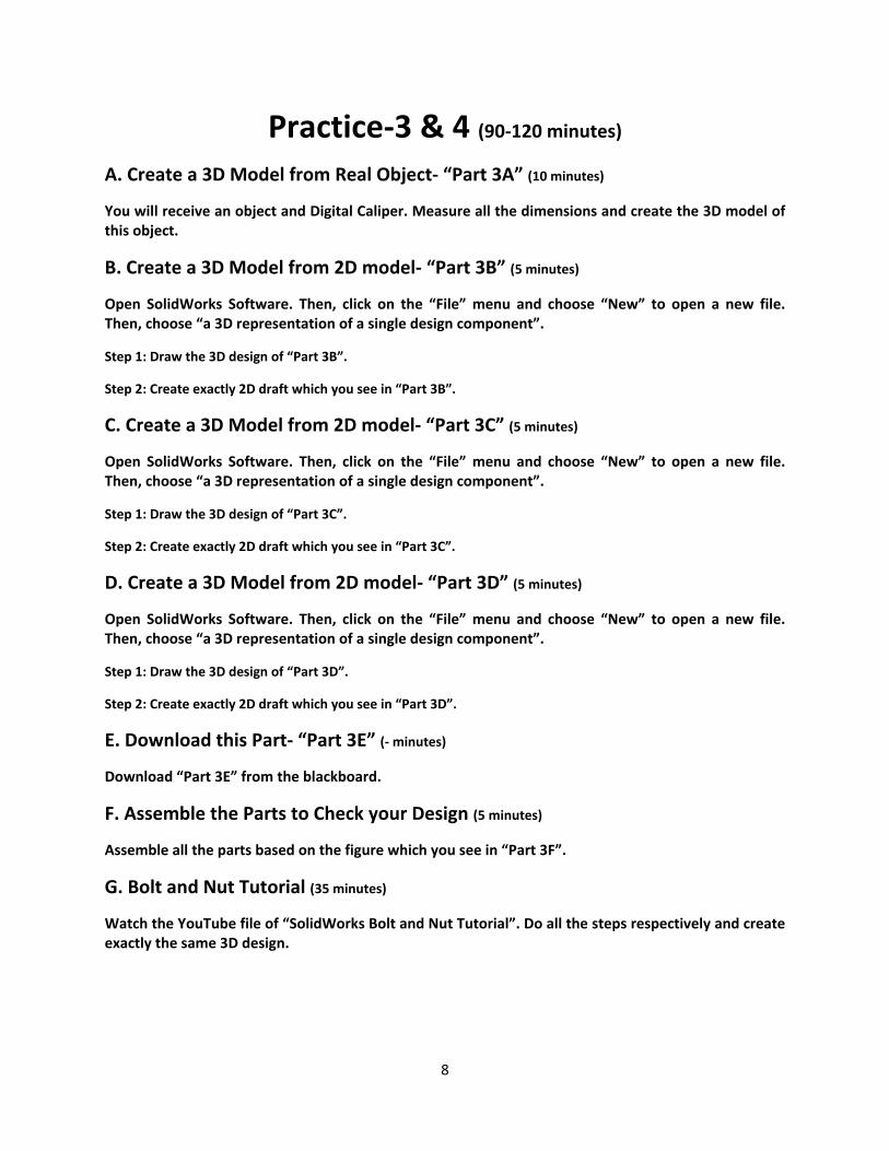
Practice‐3 & 4 (90‐120 minutes) A. Create a 3D Model from Real Object‐ “Part 3A” (10 minutes)
You will receive an object and Digital Caliper. Measure all the dimensions and create the 3D model of this object.
B. Create a 3D Model from 2D model‐ “Part 3B” (5 minutes)
Open SolidWorks Software. Then, click on the “File” menu and choose “New” to open a new file. Then, choose “a 3D representation of a single design component”.
Step 1: Draw the 3D design of “Part 3B”.
Step 2: Create exactly 2D draft which you see in “Part 3B”.
C. Create a 3D Model from 2D model‐ “Part 3C” (5 minutes)
Open SolidWorks Software. Then, click on the “File” menu and choose “New” to open a new file. Then, choose “a 3D representation of a single design component”.
Step 1: Draw the 3D design of “Part 3C”.
Step 2: Create exactly 2D draft which you see in “Part 3C”.
D. Create a 3D Model from 2D model‐ “Part 3D” (5 minutes)
Open SolidWorks Software. Then, click on the “File” menu and choose “New” to open a new file. Then, choose “a 3D representation of a single design component”.
Step 1: Draw the 3D design of “Part 3D”.
Step 2: Create exactly 2D draft which you see in “Part 3D”.
E. Download this Part‐ “Part 3E” (‐ minutes)
Download “Part 3E” from the blackboard.
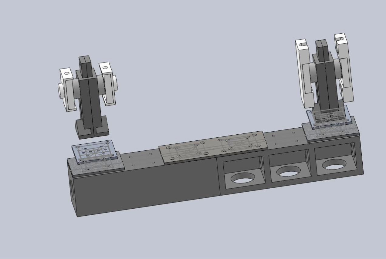
F. Assemble the Parts to Check your Design (5 minutes)
Assemble all the parts based on the figure which you see in “Part 3F”.
G. Bolt and Nut Tutorial (35 minutes)
Watch the YouTube file of “SolidWorks Bolt and Nut Tutorial”. Do all the steps respectively and create exactly the same 3D design.

9
H. Wheel Chain (25 minutes)
Watch the YouTube file of “SolidWorks Wheel Chain”. Do all the steps respectively and create exactly the same 3D design.
I. Branched Vein (optional)
Watch the YouTube file of “SolidWorks Branched Vein”. Do all the steps respectively and create exactly the same 3D design.
Submit your PDF file, which has 18 pages, by the end class. Note: You are going to submit a PDF file which has 18 pages. In the end, combine all of your PDF files and convert them into 1 PDF file with 18 pages. Your PDF file have the following pages: Page 1‐3: 3 different points of view from your 3D design from given real part (25 points) Page 4: Mechanical draft of Part 2B (5 points) Page 5: Mechanical draft of Part 2C (5 points) Page 6: Mechanical draft of Part 2D (5 points) Page 7‐9: 3 different points of view from your 3D assembly in part F (10 points) Page 10‐12: 3 different points of view from your 3D design of Part G (55 points) Page 13‐15: 3 different points of view from your 3D design of Part H (45 points) Page 16‐18: 3 different points of view from your 3D design of Part I (optional, extra points) Note: If your submitted file has other format than above, your score will be reduced 10 points. Note: only one of your group members will submit the file. Note: You may want to change your file. It would be no problem. We will only grade the final attempt of your submissions. Note: Keep all of your files (“.sldprt”) of SolidWorks Software for future practices.