
solidThinking Techniques - Nanco · 78 solidThinking Techniques Tutorial 3 - Beverage Bottle 79 3...
62
i solidThinking Techniques Designed and Written by Mark Banas
Transcript of solidThinking Techniques - Nanco · 78 solidThinking Techniques Tutorial 3 - Beverage Bottle 79 3...

i
solidThinkingTechniques
Designed and Written byMark Banas

solidThinking Techniquesii iii
ContentsTutorial 1 –Toy Car . . . . . . . . . . . . . . . . . . . . . .1Interface, primitives, and transforms
Tutorial 2 – 3D Glasses . . . . . . . . . . . . . . . . .39Curves, surfaces, and history
Tutorial 3 – Beverage Bottle . . . . . . . . . . . . .77Editing parametric points
Tutorial 4 – Basic Rendering . . . . . . . . . . . 137Lights, shaders, and image maps
Tutorial 5 – Suitcase . . . . . . . . . . . . . . . . . . 187Solids and Rounds
Tutorial 6 – Sunglasses . . . . . . . . . . . . . . . 257Guide surfaces and advanced surfacing
Tutorial 7 – Faucet . . . . . . . . . . . . . . . . . . . . 327Transition surfaces and continuity
Tutorial 8 – Car Wheel . . . . . . . . . . . . . . . . 373Symmetry and associative geometry
Tutorial 9 – Advanced Rendering . . . . . . . .411Natural lighting, environments and sketches
Introduction . . . . . . . . . . . . . . . . . . . . . . . . . . . iv
Technology brief . . . . . . . . . . . . . . . . . . . . . . . . vi
Conventions and use . . . . . . . . . . . . . . . . . . . . .xii
User Interface map . . . . . . . . . . . . . . . . . . . . . xiii
Appendix A: Keyboard Shortcuts . . . . . . . . . .459
Appendix B: Index of Tools . . . . . . . . . . . . . .460
Appendix C: Index of Tips . . . . . . . . . . . . . . .462

77Tutorial 3 - Beverage Bottle
3
In this lesson you will be building a beverage bottle using curves to defi ne its shape and surfaces to enclose it. Manipulating curves and surfaces at the Control Vertex level will be the most important and challenging part of this lesson. In previous lessons you manipulated the CVs (or points) of simple, non-parametric curves, but in this lesson you will be altering the CVs of parametric curves and surfaces. These objects will still be controlled by their parameters, but you can achieve fi ner control by editing them on the point level.
This tutorial will also introduce the concept of surface continuity, and the use of transitional surfaces to maintain that continuity. The Construction Tree will also be a very large part of this lesson as you modify curves and surfaces that will affect other, “linked” curves and surfaces.
Tutorial 3 - Beverage Bottle

solidThinking Techniques78 79Tutorial 3 - Beverage Bottle
3The fi rst step in creating our bottle is to defi ne its shape with an overall element. Since bottles are circular in plan, we can start with a simple, but powerful, parametric curve called the Circle primitive.
Part 1: Creating Parametric Curves
Because primitive objects are created relative to the active viewport (“view-relative creation”), make the Top view active by clicking inside it or by pressing and holding the Ctrl-key (Win) or the -key (Mac) while the cursor is above the view window. The title of the view will become darker when it is active.
When the title bar of the Top view is active, select the Circle tool from the Curves tab of the Modeling Toolbar. This will place a temporary circle in our scene for visible feedback of the “creation phase” of our parametric Circle. (During this phase of creation, we can also see the interactive “hotspots” that control the parameters of our object.)
The Console will prompt you to defi ne the “Local Axis Origin” and provide a default value of (0,0,0). Press Return to accept this default value, which will center our circle on the World Origin.
solidThinking Techniques78 79Tutorial 3 - Beverage Bottle
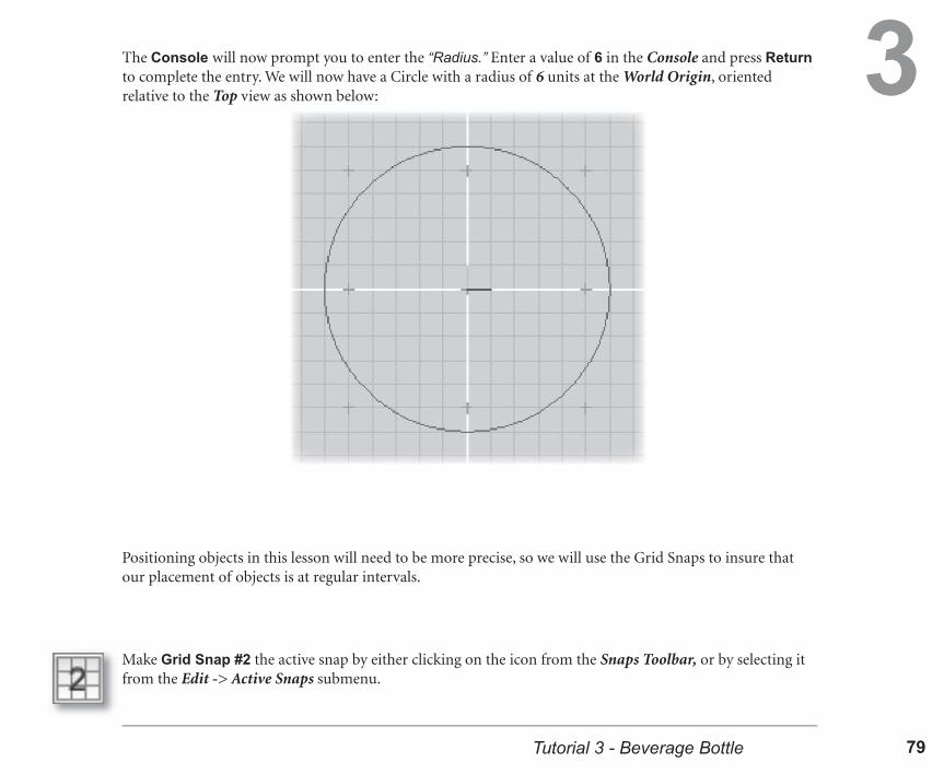
3The Console will now prompt you to enter the “Radius.” Enter a value of 6 in the Console and press Return to complete the entry. We will now have a Circle with a radius of 6 units at the World Origin, oriented relative to the Top view as shown below:
Make Grid Snap #2 the active snap by either clicking on the icon from the Snaps Toolbar, or by selecting it from the Edit -> Active Snaps submenu.
Positioning objects in this lesson will need to be more precise, so we will use the Grid Snaps to insure that our placement of objects is at regular intervals.

solidThinking Techniques80 81Tutorial 3 - Beverage Bottle
3
Now Paste a copy of our initial Circle back into our scene with Crtl-V (Win) or -V (Mac). Our pasted Circle will be in the same location as the original, so it may appear in the 3D views that no change has taken place.
In the Front view, Translate the copied Circle by clicking-and-dragging it “upward” 7 units in the positive Z direction. The active Grid Snap will make it easy to move by unit increments.
We will be creating an object that requires multiple curves to complete, so the easiest way to get multiple curves is to Copy the Circle we have already created.
While the Circle is still selected, Copy it with the Crtl-C (Win) or -C (Mac) keyboard command. This will place a copy of this parametric curve into our application clipboard.

solidThinking Techniques80 81Tutorial 3 - Beverage Bottle
3Paste a second time to place a third Circle in our scene. It will, of course, be in the exact location as our original Circle (the one that was copied at the World Origin) so we must Translate it as well.
This gives us a second Circle that is identical to the fi rst but is located 7 units above the original. We need one more curve, so we can Paste a second time (because the original Circle copy is still in the application clipboard).
Because the Translate tool has no “creation phase,” the Tool Panel is immediately active. The Translate tool panel has options and input fi elds for the “From” and “To” coordinates. The input areas are in the order of X, Y, and then Z, from left to right, which correspond to units along each axis.
Invoke the Translate tool by either clicking the Translate tool icon, or (faster) pressing the “T” shortcut.
Click in the “To” section’s Z input area and enter a value of 13 units. Press Return to accept the value and then press ESC to end the Translate action.
solidThinking Techniques82 83Tutorial 3 - Beverage Bottle
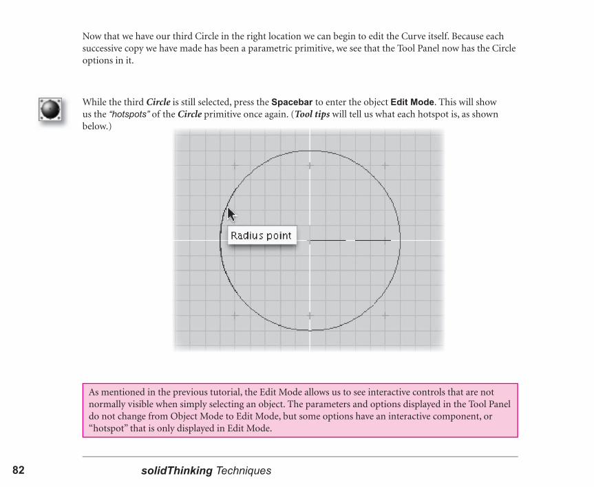
3Now that we have our third Circle in the right location we can begin to edit the Curve itself. Because each successive copy we have made has been a parametric primitive, we see that the Tool Panel now has the Circle options in it.
While the third Circle is still selected, press the Spacebar to enter the object Edit Mode. This will show us the “hotspots” of the Circle primitive once again. (Tool tips will tell us what each hotspot is, as shown below.)
As mentioned in the previous tutorial, the Edit Mode allows us to see interactive controls that are not normally visible when simply selecting an object. The parameters and options displayed in the Tool Panel do not change from Object Mode to Edit Mode, but some options have an interactive component, or “hotspot” that is only displayed in Edit Mode.

solidThinking Techniques82 83Tutorial 3 - Beverage Bottle
3
As you drag the Radius hotspot, you may notice that it does not always “snap” to whole unit increments (as displayed in the Radius value in the Tool Panel). This is because the Grid Snap in solidThinking affects the Mouse Cursor location, not necessarily the hotspot or object being dragged. You can move the Mouse Cursor around the circumference of the Circle to snap whatever part is closest to the nearest grid point.
In the Top view, click-and-drag the “Radius Point” hotspot “inward” toward the center of the Circle until the Radius value displayed in the Circle tool panel is 4. (The active Grid Snap will make this easier.)
When the Radius is set, press Spacebar again to exit Edit Mode and return to the Object Mode.

solidThinking Techniques84 85Tutorial 3 - Beverage Bottle
3While this smaller Circle is still selected, Copy and Paste it back into our scene. This will clear the previous Circle from the clipboard and place a copy of this smaller one into our scene well “above” the earlier Circles. (Again, only the number of curves in our World Browser will appear to change, since this copy is Pasted “on top” of the original.)
In the Perspective view, click-and-drag on the top (selected) Circle to Translate it 2 units upward in the positive Z direction. The Grid Snap will make it easy to recognize the “snap” in this view, but the Translate tool panel will also refl ect this incremental move as well.

solidThinking Techniques84 85Tutorial 3 - Beverage Bottle
3
If we look at our curves in the Perspective view, we can see that we have four NURBS Circle primitives positioned above each other, and that some have different radii. These will form the “ribs” of a surface that we will create next.
Once this fourth Circle is positioned, change its Radius to be 2 by entering this value in the Circle tool panel. (We do not have to enter Edit Mode to make this modifi cation to the Radius parameter in the Tool Panel.)
solidThinking Techniques86 87Tutorial 3 - Beverage Bottle
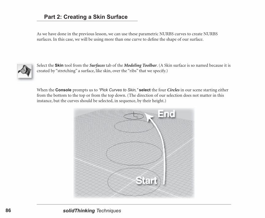
3As we have done in the previous lesson, we can use these parametric NURBS curves to create NURBS surfaces. In this case, we will be using more than one curve to defi ne the shape of our surface.
Select the Skin tool from the Surfaces tab of the Modeling Toolbar. (A Skin surface is so named because it is created by “stretching” a surface, like skin, over the “ribs” that we specify.)
Part 2: Creating a Skin Surface
When the Console prompts us to “Pick Curves to Skin,” select the four Circles in our scene starting either from the bottom to the top or from the top down. (The direction of our selection does not matter in this instance, but the curves should be selected, in sequence, by their height.)
solidThinking Techniques86 87Tutorial 3 - Beverage Bottle
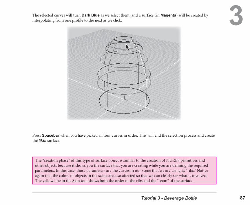
3The selected curves will turn Dark Blue as we select them, and a surface (in Magenta) will be created by interpolating from one profi le to the next as we click.
Press Spacebar when you have picked all four curves in order. This will end the selection process and create the Skin surface.
The “creation phase” of this type of surface object is similar to the creation of NURBS primitives and other objects because it shows you the surface that you are creating while you are defi ning the required parameters. In this case, those parameters are the curves in our scene that we are using as “ribs.” Notice again that the colors of objects in the scene are also affected so that we can clearly see what is involved. The yellow line in the Skin tool shows both the order of the ribs and the “seam” of the surface.

solidThinking Techniques88 89Tutorial 3 - Beverage Bottle
3To clearly see the surface we have created, switch the Perspective view to Shaded display mode. (Toggle the small “S” button on the right side of the view title bar.)
This Skin surface is connected to the four parametric Circles in our scene through the Construction Tree. This means that there is a active relationship between the position, orientation, and shape of each Circle, and the resulting shape of the Skin surface. We can see that the parameters for the Skin surface are extensive, and we know from the previous tutorial that modifying any of the “source curves” will also change the surface. However, in this case, our source curves are parametric Circle primitives which seem to only have certain parameters to edit. Part of the true power in solidThinking is that all parametric curves and surfaces also are NURBS objects with editable points (or Control Vertices) that we can access and manipulate.

solidThinking Techniques88 89Tutorial 3 - Beverage Bottle
3We are now going to touch on one of the most powerful features of solidThinking - the ability to edit the NURBS points of a parametric object without losing any of its parameters. Not only this, but we will be editing this object “inside” our Construction Tree, so the changes we make will be refl ected instantly in the objects that are linked to it.
Whenever an object is selected (either Red or Magenta) we can see the “source” curves in our scene highlighted in Green. This makes it easier to see and select the source objects if they are visible in our scene. It is also easier to select curves in Wireframe display mode because curves have “pick priority” over surfaces in this display mode, while in Shaded display, surfaces have priority.
Part 3: Editing Points on Parametric Objects
While our Skin object is still selected, we can clearly see our original “source” Circles in the Wireframe dis-play of either the Front or Right views, as shown below . (The Top view has too many “wires” in the way.)

solidThinking Techniques90 91Tutorial 3 - Beverage Bottle
3Select the second “source” Circle (in Green) from the bottom of our Skin object by clicking directly on it. The curve will turn Red and the surface Blue, to show that we have “swapped” the selection in one click (deselecting and selecting at the same time).
Press the Spacebar to enter the Edit Mode for this object. This will show the parameter “hotspots” in Dark Blue in our interactive views. This normal state is called Parameter Edit and is denoted by the typical icons seen to the left.
Next, press Alt-Spacebar (Win) or Option-Spacebar (Mac), which will change our Parameter Edit over to Point Edit. This is a “special state” of the Edit Mode and is denoted by the icon combination seen to the left. (The difference in icons is slight, but the difference on screen is quite large!)
solidThinking Techniques90 91Tutorial 3 - Beverage Bottle
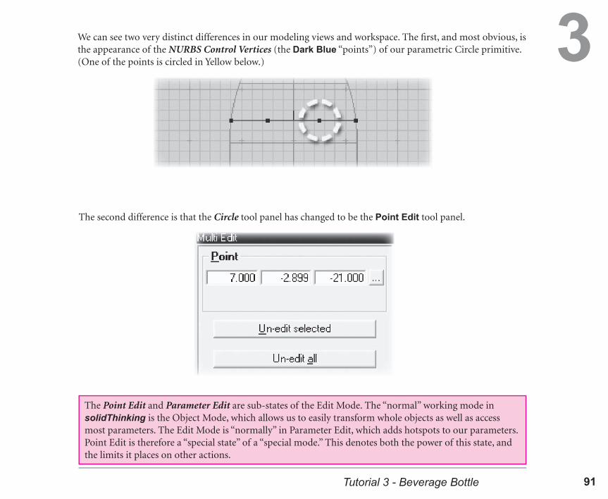
3We can see two very distinct differences in our modeling views and workspace. The fi rst, and most obvious, is the appearance of the NURBS Control Vertices (the Dark Blue “points”) of our parametric Circle primitive. (One of the points is circled in Yellow below.)
The second difference is that the Circle tool panel has changed to be the Point Edit tool panel.
The Point Edit and Parameter Edit are sub-states of the Edit Mode. The “normal” working mode in solidThinking is the Object Mode, which allows us to easily transform whole objects as well as access most parameters. The Edit Mode is “normally” in Parameter Edit, which adds hotspots to our parameters. Point Edit is therefore a “special state” of a “special mode.” This denotes both the power of this state, and the limits it places on other actions.

solidThinking Techniques92 93Tutorial 3 - Beverage Bottle
3If we look at the CVs of our parametric Circle in the Top view, we can see that it is made up of 8 points. This number is specifi ed as a value in the parameters of the Circle tool panel.
Press the keyboard shortcut to exit the Point Edit state (Alt-Spacebar (Win), Option-Spacebar (Mac)). This will return us to Parameter Edit so we can see the Circle tool panel again, but we are still in Edit Mode.
If we wanted to select another object and view its hotspots and parameters at this point, we could not simply select it like we normally do in the Object Mode. This is because in the Edit Mode, either hotspots or points are displayed on screen to be selected. Selecting these “parts” of an object without accidentally selecting another entire object in the scene would be diffi cult, so the interactive selection of other objects is disabled while in Edit Mode.
solidThinking Techniques92 93Tutorial 3 - Beverage Bottle
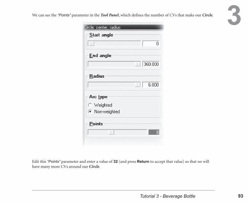
3We can see the “Points” parameter in the Tool Panel, which defi nes the number of CVs that make our Circle.
Edit this “Points” parameter and enter a value of 32 (and press Return to accept that value) so that we will have many more CVs around our Circle.

solidThinking Techniques94 95Tutorial 3 - Beverage Bottle
3Press the keyboard shortcut to re-enter the Point Edit state (Alt-Spacebar (Win), Option-Spacebar (Mac)) so that we can see how this parametric setting has a direct infl uence on the CVs of our NURBS curve.
It is good to keep in mind that changing some parameters in your Tool Panel may not have an immediately visible effect on the object. In this case, we can only see the effect of increasing the “Points” parameter if we are in Edit Mode and switch to Point Edit.
Because these “new” CVs are selectable and editable, just like the “hotspots” in Parameter Edit, we can now manipulate our parametric Circle on the point level. This can be done without losing any of the parametric qualities of the original NURBS circle primitive!

solidThinking Techniques94 95Tutorial 3 - Beverage Bottle
3Select the four highlighted points shown below by clicking-and-dragging a “selection box” around them. (They will turn Yellow after you have released the mouse button, unlike the illustration below which shows them already yellow only for clarity.)
Selecting these points is similar to selecting other objects, or the CVs of a non-parametric object. You can drag a selection box around multiple points, and then hold down the Ctrl key to add to this selection.
You can see in the example above that it is easy to select points that lie next to each other, or even across from each other, by using a selection box instead of clicking on each separate point while holding the Ctrl key down. We will use this method of selecting points to select half of the points in this Circle in a specifi c pattern, but only using four click-and-drag actions.

solidThinking Techniques96 97Tutorial 3 - Beverage Bottle
3While holding down the Ctrl key to add to the current point selection, click-and-drag selection boxes around the points highlighted in Yellow in the image below. You will notice that all of them can be selected in groups of four by carefully positioning your cursor before dragging the box out.
We can now edit all of these points as a group using the standard Transform tools of Translate, Rotate, and Scale.
Invoke the Scale tool by either pressing the “S” shortcut, or selecting its icon from the Transform tab of the Modeling Toolbar.

solidThinking Techniques96 97Tutorial 3 - Beverage Bottle
3When the Scale tool panel appears, select the “Scale” input area and enter a value of 0.9, and then press Return.
Press ESC to end the Scale action and to clearly see the effect that this simple change has on the location of the points of our parametric Circle.

solidThinking Techniques98 99Tutorial 3 - Beverage Bottle
3Press the keyboard shortcut to exit the Point Edit state (Alt-Spacebar (Win), Option-Spacebar (Mac)). This will return us to Parameter Edit inside Edit Mode, and the hotspots for certain interactive parameters will reappear, as well as the Circle tool panel.
We can see clearly in the Shaded display of the Perspective view that changing the points of one of the “source curves” of the Skin surface automatically changes the shape of the resulting surface as well.
Editing these CVs does not change the parametric settings of the selected object, only the position of its internal points. When you switch back to Parameter Edit, or even Object Mode, you can still access all of the parameters for the object, and these parametric controls will still have their intended effect on your object.

solidThinking Techniques98 99Tutorial 3 - Beverage Bottle
3
After you are done experimenting with the Radius parameter of our edited curve, press the Spacebar to exit the Edit Mode. This will return us to the Object Mode, where we can freely work with all of the objects in our scene.
Although it is not necessary, we can freely experiment with altering the parameters of the Circle after we have edited the points. In the Top view, Click-and-drag on the Radius hotspot of this selected Circle , and watch the effect it has on the Skin surface in the Shaded Perspective view.
Return the Radius of the Circle to a value of 6, by either dragging the hotspot back to its original position, or by entering a value of 6 directly in the Radius input box of the Circle tool panel.

solidThinking Techniques100 101Tutorial 3 - Beverage Bottle
3The surface we have already created will be the top half of our bottle. We will need to add a “mouth” to the bottle, so that we can represent the opening accurately. It will also provide a place for a “cap” to rest on our fi nished bottle as well.
Part 4: Creating and Blending the Mouth
In the Top view, select the innermost curve of the Skin object, as shown below. (Because the Wireframe display method gives pick “priority” to curves, it will be easy to do this in this view without selecting the Skin itself.)
While this smaller Circle is still selected, Copy and Paste it back into our scene.

solidThinking Techniques100 101Tutorial 3 - Beverage Bottle
3Invoke the Translate tool (“T”) and move the copied Circle “upward” by 1 unit in the positive Z direction.
In the Circle tool panel for this copied curve, enter a value of 1.5 in the Radius input box, and press Return to accept this value.

solidThinking Techniques102 103Tutorial 3 - Beverage Bottle
3The Console will prompt you to “Pick Profi le Curve.” Select the most recent copy we made of our Circle primitive.
Select the Extrude tool from the Surfaces tab of the Modeling Toolbar.
This surface will be the base of the “mouth” of our bottle. Next we will connect this simple surface to the Skin surface to visually “blend” between the nearest edges of the two, separated surfaces.
At the next Console prompt “Extrusion Length,” enter a value of 2, and press Return to accept this value and to complete the creation phase of this tool.

solidThinking Techniques102 103Tutorial 3 - Beverage Bottle
3Click on the icon for the Blend Surface tool in the Surfaces tab of the Modeling Toolbar.
The Console will fi rst prompt you to “Pick Surface #1.” Select the Extrude surface we just created.
The Blend Surface tool will then highlight the “edges” of the selected surface in Dark Blue and show “points” at the Start point of each edge (as shown below).
Before we go on to the next tool, it will be helpful to switch the Perspective view to Wireframe display mode, and to Zoom Selected, so that our new Extrude is the center of the view.
solidThinking Techniques104 105Tutorial 3 - Beverage Bottle
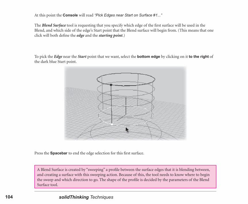
3To pick the Edge near the Start point that we want, select the bottom edge by clicking on it to the right of the dark blue Start point.
Press the Spacebar to end the edge selection for this fi rst surface.
At this point the Console will read “Pick Edges near Start on Surface #1...”
The Blend Surface tool is requesting that you specify which edge of the fi rst surface will be used in the Blend, and which side of the edge’s Start point that the Blend surface will begin from. (This means that one click will both defi ne the edge and the starting point.)
A Blend Surface is created by “sweeping” a profi le between the surface edges that it is blending between, and creating a surface with this sweeping action. Because of this, the tool needs to know where to begin the sweep and which direction to go. The shape of the profi le is decided by the parameters of the Blend Surface tool.

solidThinking Techniques104 105Tutorial 3 - Beverage Bottle
3Next, the Console will prompt you to “Pick Surface #2.” At this point, select the Skin surface that is just below the Extrude we selected fi rst. (It does not matter where you click on the Skin to select it for the tool.)
The edges of this surface will now be highlighted in the same way as the fi rst surface we selected for this tool.
When the Console prompts you to “Pick Edges near Start on Surface #2...” select the top edge of the Skin surface, again to the right of the dark blue Start Point. Press Spacebar to end the edge selection.
Selecting the second edge will end the “creation phase” and will create a Blend Surface between the specifi ed edges of the two surfaces.

solidThinking Techniques106 107Tutorial 3 - Beverage Bottle
3We can see that the Blend Surface is not exactly what we want in this situation. We can now easily modify the parameters to achieve the blend we are looking for.
In the Blend Surface tool panel, select the Tangents option to “Invert surface #2.” This will correct the “bulge” we see at the bottom of our blend.
The edge of a surface has two possible tangent directions: toward the surface, and away from it. In this case, the Blend Surface tool simply chose the “wrong” direction for our current purposes.
solidThinking Techniques106 107Tutorial 3 - Beverage Bottle
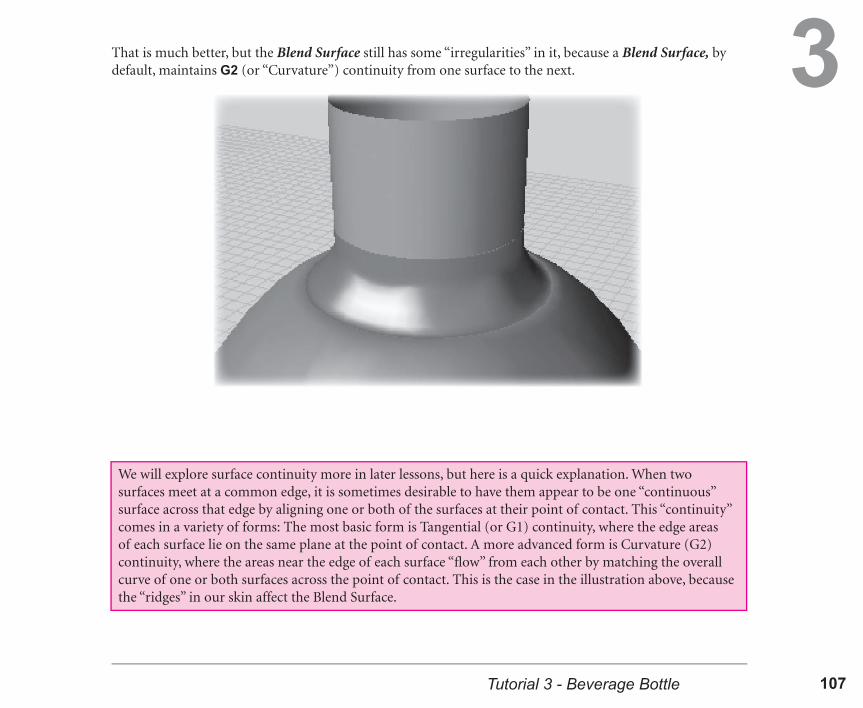
3That is much better, but the Blend Surface still has some “irregularities” in it, because a Blend Surface, by default, maintains G2 (or “Curvature”) continuity from one surface to the next.
We will explore surface continuity more in later lessons, but here is a quick explanation. When two surfaces meet at a common edge, it is sometimes desirable to have them appear to be one “continuous” surface across that edge by aligning one or both of the surfaces at their point of contact. This “continuity” comes in a variety of forms: The most basic form is Tangential (or G1) continuity, where the edge areas of each surface lie on the same plane at the point of contact. A more advanced form is Curvature (G2) continuity, where the areas near the edge of each surface “fl ow” from each other by matching the overall curve of one or both surfaces across the point of contact. This is the case in the illustration above, because the “ridges” in our skin affect the Blend Surface.

solidThinking Techniques108 109Tutorial 3 - Beverage Bottle
3In the Blend Surface tool panel, select the G1 Continuity option for “Only G1 on Surface #2.” This means that as the Blend Surface meets the Skin, the resulting surface will have Tangential (G1) continuity across that edge.
Now we have a smooth Blend Surface between the edge of the Skin and the Extrude that is the “mouth” of our bottle.
solidThinking Techniques108 109Tutorial 3 - Beverage Bottle
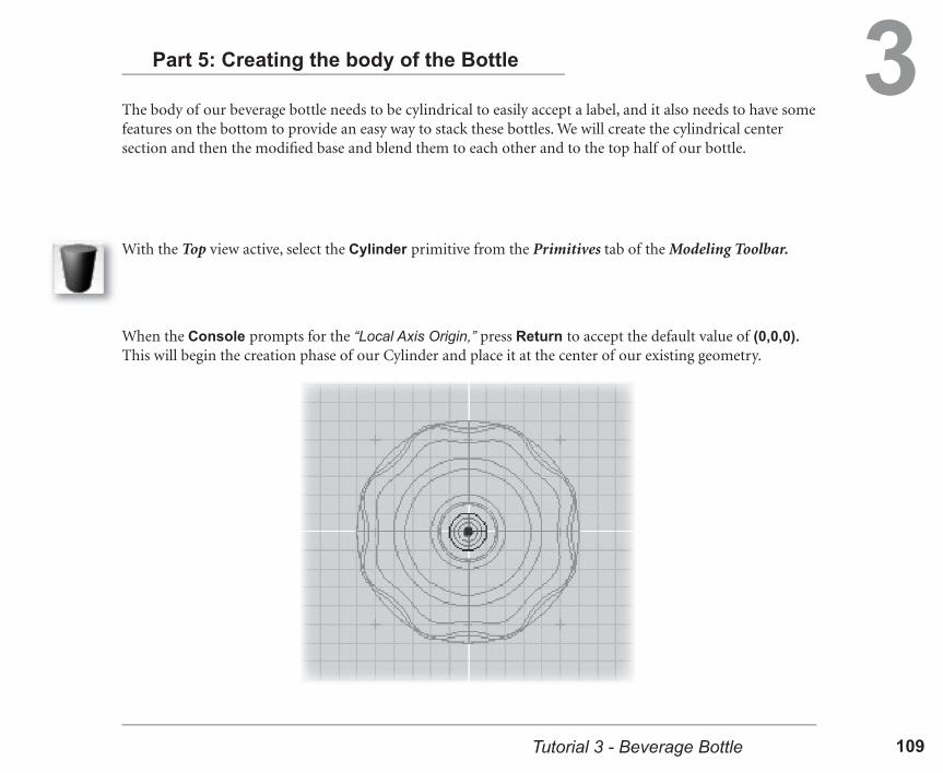
3The body of our beverage bottle needs to be cylindrical to easily accept a label, and it also needs to have some features on the bottom to provide an easy way to stack these bottles. We will create the cylindrical center section and then the modifi ed base and blend them to each other and to the top half of our bottle.
Part 5: Creating the body of the Bottle
With the Top view active, select the Cylinder primitive from the Primitives tab of the Modeling Toolbar.
When the Console prompts for the “Local Axis Origin,” press Return to accept the default value of (0,0,0). This will begin the creation phase of our Cylinder and place it at the center of our existing geometry.

solidThinking Techniques110 111Tutorial 3 - Beverage Bottle
3Next, the Console will prompt for the “Top Radius,” and then the “Bottom Radius.” Enter a value of 5 for each of these two parameters.
At the Console prompt for “Height,” enter a value of -10. This will enter the creation phase, and then you should have a cylinder of the size and location shown in the image below:
You may notice in the screen image above that the 3D grid is not visible. This is because it was turned off to provide an uninterrupted view of our bottle as it crosses the World Origin. You can turn this grid display off by going to the application Preferences, and in the Views tab, toggle the option for “Grid in 3D views.”

solidThinking Techniques110 111Tutorial 3 - Beverage Bottle
3In the Front view, click-and-drag on this new cylinder to Translate it “down” in the negative Z axis by 2 units.
Once this Cylinder has been dragged a short distance away from the top of the bottle, we can see that it is still closed at the top and bottom.
We will be using this cylinder as a “tube” rather than a solid, so in the Cylinder Tool Panel, uncheck the Caps options for both “Top” and “Bottom.”
solidThinking Techniques112 113Tutorial 3 - Beverage Bottle
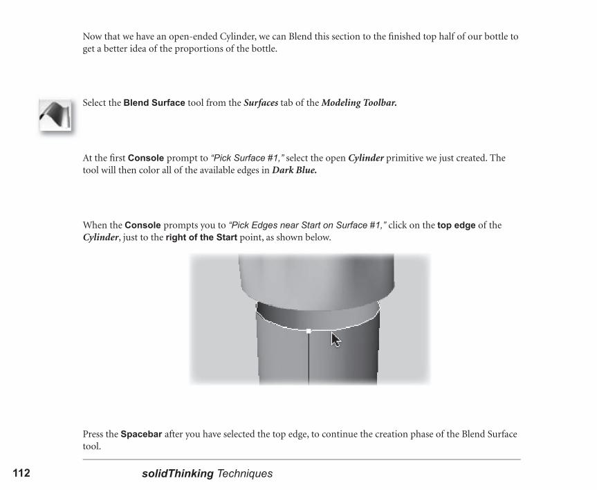
3Now that we have an open-ended Cylinder, we can Blend this section to the fi nished top half of our bottle to get a better idea of the proportions of the bottle.
Select the Blend Surface tool from the Surfaces tab of the Modeling Toolbar.
At the fi rst Console prompt to “Pick Surface #1,” select the open Cylinder primitive we just created. The tool will then color all of the available edges in Dark Blue.
When the Console prompts you to “Pick Edges near Start on Surface #1,” click on the top edge of the Cylinder, just to the right of the Start point, as shown below.
Press the Spacebar after you have selected the top edge, to continue the creation phase of the Blend Surface tool.

solidThinking Techniques112 113Tutorial 3 - Beverage Bottle
3The Console will now prompt you to “Pick Surface #2.” Select the Skin surface that makes up the majority of the top of our beverage bottle design.
Next, when the Console asks you to “Pick Edges near Start on Surface #2,” click on the bottom edge of the Skin, and again, click to the right of the Start point, as shown below.
Press the Spacebar to end the edge selection for Surface #2, and to end the creation phase for our Blend Surface. This will provide us with a very good Blend between these two surfaces without needing to adjust any parameters at all.
solidThinking Techniques114 115Tutorial 3 - Beverage Bottle
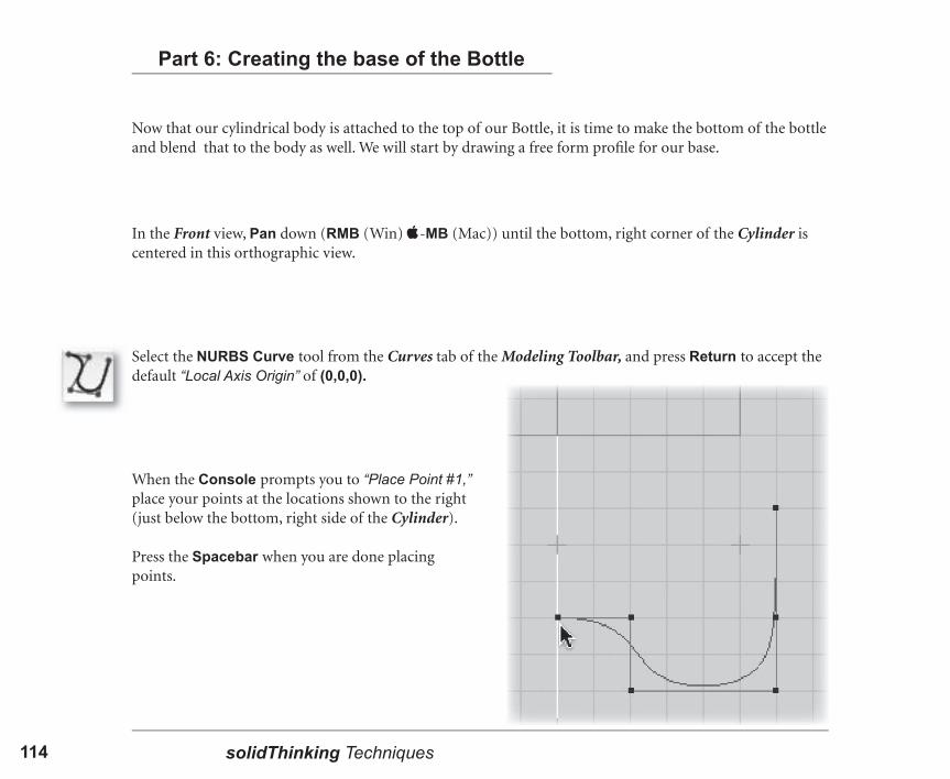
3Now that our cylindrical body is attached to the top of our Bottle, it is time to make the bottom of the bottle and blend that to the body as well. We will start by drawing a free form profi le for our base.
Part 6: Creating the base of the Bottle
Select the NURBS Curve tool from the Curves tab of the Modeling Toolbar, and press Return to accept the default “Local Axis Origin” of (0,0,0).
In the Front view, Pan down (RMB (Win) -MB (Mac)) until the bottom, right corner of the Cylinder is centered in this orthographic view.
When the Console prompts you to “Place Point #1,” place your points at the locations shown to the right (just below the bottom, right side of the Cylinder).
Press the Spacebar when you are done placing points.

solidThinking Techniques114 115Tutorial 3 - Beverage Bottle
3Select the Lathe tool from the Surfaces tab of the Modeling Toolbar.
We can now Lathe this profi le around its Local Axis Origin, which we already specifi ed as (0,0,0), the same as the World Origin. This is yet another way to create a cylindric surface from a curve.
When the Console prompts you to “Pick Profi le Curve,” select the NURBS Curve that we just created below the Cylinder body of our bottle.
The creation phase of our Lathe will begin with the placement of an interactive guide object to give us feedback while working. In this case, this initial object is exactly what we want, so we can skip all of the rest of the Console prompts by pressing Ctrl-Enter (Win) or -Return (Mac). This will end the creation phase immediately.

solidThinking Techniques116 117Tutorial 3 - Beverage Bottle
3To fully enclose our bottle, we will now Blend this Lathed base with the Cylinder primitive above it.
Select the Blend Surface tool from the Surfaces tab of the Modeling Toolbar.
When the Console prompts you to “Pick Surface #1,” select the Cylinder that we just created below the Cylinder body of our bottle.
When the Console prompts you to “Pick Edges near Start on Surface #1,” click on the top edge of the Lathe, just to the right of the Start point, as shown below.

solidThinking Techniques116 117Tutorial 3 - Beverage Bottle
3The Console will now prompt you to “Pick Surface #2.” Select the open-ended Cylinder primitive that is the body of our beverage bottle design.
Next, when the Console asks you to “Pick Edges near Start on Surface #2,” click on the bottom edge of the Cylinder, and to stay consistent, click to the right of the Start point, as shown below.
Press the Spacebar after you have selected the top edge, which will end this phase of the Blend Surface tool.
Press the Spacebar when you have selected the Edge. This will end the creation phase and provide us with our Blend Surface.

solidThinking Techniques118 119Tutorial 3 - Beverage Bottle
3
We can easily change the Tangent direction, by going to the Blend Surface tool panel and checking the Tangent option to “Invert Surface #2.”
This will provide us with the smoothly blended surface that we are after.
We can see that the top Tangent “balloons” outward, indicating that it is reversed.
solidThinking Techniques118 119Tutorial 3 - Beverage Bottle
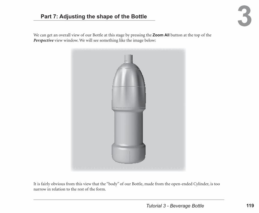
3Part 7: Adjusting the shape of the Bottle
We can get an overall view of our Bottle at this stage by pressing the Zoom All button at the top of the Perspective view window. We will see something like the image below:
It is fairly obvious from this view that the “body” of our Bottle, made from the open-ended Cylinder, is too narrow in relation to the rest of the form.

solidThinking Techniques120 121Tutorial 3 - Beverage Bottle
3Select the Cylinder surface in any one of the interactive views, and change the Top and Bottom Radius values for the Cylinder to be 5.5.
This thickens the center portion of our bottle, and the Blends above and below the Cylinder automatically adjust to meet the surface as it changes.

solidThinking Techniques120 121Tutorial 3 - Beverage Bottle
3Because we have the freedom of the Construction Tree and the parametric controls of our various surfaces, we can add interest to our bottle without having to build any further surfaces.
Select the Skin surface from the top of our bottle, and then press the Zoom Selected button at the top of the Perspective view window. This will make it easier to perform and evaluate some adjustments that we are going to make.
Press the Spacebar to enter the Edit Mode, so we can see the interactive controls of the Skin. We will see Dark Blue lines in the approximate locations of the “ribs,” or source curves, that we used when building this Skin.
Select the second line from the bottom. It will turn Yellow to show it is selected and a Tool Tip will come up and tell us which curve the hotspot represents.

solidThinking Techniques122 123Tutorial 3 - Beverage Bottle
3While this hotspot is selected, change the Seam Position in the Skin tool panel to be 0.1. (This small amount is enough to give us a pretty dramatic effect.) The Option for “User Seam” will automatically engage.
Changing the Seam Position at one “rib” hotspot changes the point at which the Skin surface “fl ows” across the source curve that is associated with that hotspot. However, we are not moving or affecting the source curve in any way. Only the seam of the surface is moving. We could derive a similar shape by actually rotating our source curve along the same axis as the Skin progresses, but this is not always easy to do, and in some cases may disturb other geometry built from that curve. By changing only this parameter, we have direct control over the surface and can “reset” our rib rotation at any time, after any number of interactive changes.
You can continue to evaluate the various shapes that adjusting these positions can create. When you are satisfi ed with a fi nal Seam Position value, press the Spacebar to exit Edit Mode and return to Object Mode.

solidThinking Techniques122 123Tutorial 3 - Beverage Bottle
3Part 8: Editing points on a parametric surface
Our Beverage Bottle is just about complete, but it needs some additional features on the bottom of it, to aid in stacking it for distribution and to add stability to the shape when it is resting on a shelf. In this portion of the tutorial we will again be editing the points of a parametric object, but in this case it is a surface, not a curve.
Select the Lathe surface that is the base of our bottle, and press the large Zoom Selected button in the Application Toolbar. (This button differs from the individual Zoom buttons in each view, because it will Zoom all of the orthographic windows at once.)
In order to keep all of these Orthographic views aligned to one another, we can make the Ortho Adjust mode active by clicking the icon for this mode that is in the Application Toolbar, right next to the global Zoom Selected from above.
First we will set up our workspace so that we can concentrate on this one part of our model.
And fi nally, while the Lathe surface is still selected, press the Zoom Selected button that is at the top of Perspective view, so that the camera is focused on this surface as well.
The global Zoom Selected button does not zoom in our Perspective view as well, because that view is not orthographic, and zooming in it can sometimes have very different results from the orthographic views.

solidThinking Techniques124 125Tutorial 3 - Beverage Bottle
3To see the individual points that make up our parametric Lathe surface, we need to use the Point Edit modifi er of the Edit Mode, just as we did earlier to see the points of our parametric Circle.
Press the Spacebar to enter Edit Mode, and then press Alt-Spacebar (Win) or Option-Spacebar (Mac) to use the Point Edit modifi er of Edit Mode.
Again, this allows us to see and edit the individual points that make up the NURBS surface, even though it remains a parametric object with all of its controls intact.
We can see on screen that the CVs of our parametric object match the position of the CVs of the source curve, and are repeated around the Lathe at 8 regular intervals. This corresponds to the number of points specifi ed in the parametric controls of our Lathe. Therefore, the number and position of the CVs in our Lathe are simply the multiplication of the source curve CVs around the Lathe axis.

solidThinking Techniques124 125Tutorial 3 - Beverage Bottle
3For a fi ner level of control over this surface, we can increase the number of points used in the creation of the Lathe. This will add another 6 CVs (the number in our source curve) to our surface for each additional “point” in the revolution, but the shape of the surface will not change very much.
Press Alt-Spacebar (Win) or Option-Spacebar (Mac) to exit the Point Edit and return to Parameter Edit, while remaining in Edit Mode. This will allow us to see and manipulate the parameters of our Lathe directly in the tool panel and in the 3D views.
In the Lathe tool panel, change the number of Points to be 16. This will give us greater local control over our surface when we edit its points.
After making this adjustment, return to Point Edit by pressing Alt-Spacebar (Win) or Option-Spacebar (Mac) again. (After this lesson, this keyboard shortcut will not be explicitly written every time.)
Just like our earlier work with the parametric Circle, we can see that the parameters of the Lathe have a direct effect on the underlying points of the surface.

solidThinking Techniques126 127Tutorial 3 - Beverage Bottle
3In the Top view, drag a selection box around each set of points shown selected below. (Remember to hold down the Ctrl key while clicking-and-dragging to select additional points.)
To add the stacking and stability “lobes” at the bottom of our bottle, we will “pull down” some of the points of our Lathe. To make it easier to change only the points that we desire, we will use a powerful feature of the Point Edit mode called Un-Edit.
From this view, it will appear that 16 points have been selected, but we have actually selected the points “below” the ones visible as well, which is what we want.

solidThinking Techniques126 127Tutorial 3 - Beverage Bottle
3In the Front view, Translate the selected points “down” by 2 units in the negative Z direction.
(You can interactively Translate these points by invoking the Translate tool with the “T” shortcut, and then clicking-and-dragging outside of the model to avoid selecting other points.)
We can see the dramatic effect this change has on our Lathe and the associated Blends. This is perhaps too dramatic.
solidThinking Techniques128 129Tutorial 3 - Beverage Bottle
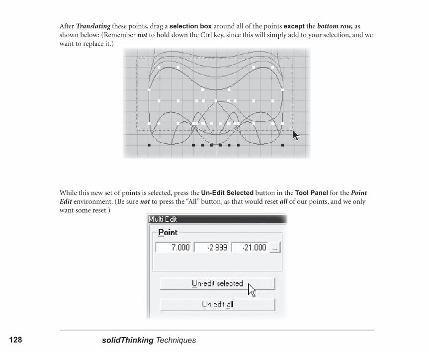
3After Translating these points, drag a selection box around all of the points except the bottom row, as shown below: (Remember not to hold down the Ctrl key, since this will simply add to your selection, and we want to replace it.)
While this new set of points is selected, press the Un-Edit Selected button in the Tool Panel for the Point Edit environment. (Be sure not to press the “All” button, as that would reset all of our points, and we only want some reset.)

solidThinking Techniques128 129Tutorial 3 - Beverage Bottle
3All of the selected points “jumped” back to their original positions! Some of these points were among the fi rst set that we Translated down, and this one button has returned them to their “Un-Edited “ state.
There are two important things to note about this Un-Edit function. Nothing happened to the points that were already in their original, parametric positions, because they were never “edited.” In addition, the points we did edit “remembered” their original positions, despite the fact that the Translate tool is not a part of our Construction Tree.
These behaviors are due to the persistent nature of parametric objects in solidThinking. If our Lathe surface was not a parametric object, then its individual points would not have a parametric state to “remember.”
The Un-Edit function in the Point Edit environment will work at any time, after any number of modifi cations. Even after you have gone on to other actions, or closed and re-opened the fi le. The reason that the points of a parametric object “remember” their original positions is because the parameters that defi ned their original positions are still intact, even after many point-edits. This is a very powerful tool, but it has one disadvantage, however: the points only “remember” their original parametric position, even if you have made multiple changes to their positions. This is why it is called “Un-Edit” instead of Undo.
solidThinking Techniques130 131Tutorial 3 - Beverage Bottle
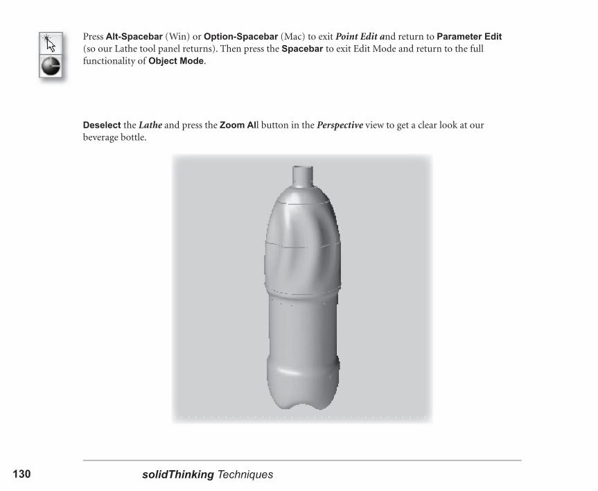
3Deselect the Lathe and press the Zoom All button in the Perspective view to get a clear look at our beverage bottle.
Press Alt-Spacebar (Win) or Option-Spacebar (Mac) to exit Point Edit and return to Parameter Edit (so our Lathe tool panel returns). Then press the Spacebar to exit Edit Mode and return to the full functionality of Object Mode.

solidThinking Techniques130 131Tutorial 3 - Beverage Bottle
3Part 9: Adding and Aligning the Cap
The only object that is missing from our bottle is a cap. We can use a simple primitive because this bottle is only a rough design of a bottle, not detailed enough to be produced.
The Console will then prompt for the “Top” and “Bottom Radii.” Enter a value of 2 for both radii, and when the Console asks for the Height of the Cylinder, enter a value of 3 units. This will provide us with a suitable sized Cylinder for our cap.
With the Top view active, select the Cylinder primitive tool and press Return to accept the default “Local Axis Origin” of 0,0,0. This will align our new object with the center of our existing bottle.
solidThinking Techniques132 133Tutorial 3 - Beverage Bottle
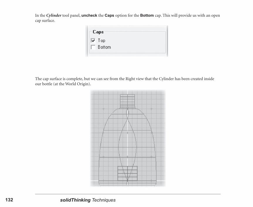
3In the Cylinder tool panel, uncheck the Caps option for the Bottom cap. This will provide us with an open cap surface.
The cap surface is complete, but we can see from the Right view that the Cylinder has been created inside our bottle (at the World Origin).
solidThinking Techniques132 133Tutorial 3 - Beverage Bottle
3We can quickly and precisely align the cap with the top of our bottle using one of the Alignment tools in solidThinking’s Modeling Toolbar.
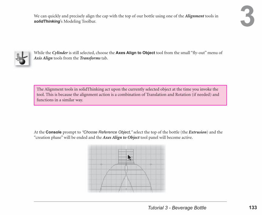
While the Cylinder is still selected, choose the Axes Align to Object tool from the small “fl y-out” menu of Axis Align tools from the Transforms tab.
The Alignment tools in solidThinking act upon the currently selected object at the time you invoke the tool. This is because the alignment action is a combination of Translation and Rotation (if needed) and functions in a similar way.
At the Console prompt to “Choose Reference Object,” select the top of the bottle (the Extrusion) and the “creation phase” will be ended and the Axes Align to Object tool panel will become active.

solidThinking Techniques134 135Tutorial 3 - Beverage Bottle
3We can see very little interactive change in our cap Cylinder, and this is only because its Orientation was already aligned to the axes of the Extrusion (being centered at the World Origin). In the Axis Align to Object tool panel, check the option for Position alignment as well.
And this will perfectly align our cap Cylinder and the top “mouth” of our bottle, fi nishing off our model!

solidThinking Techniques134 135Tutorial 3 - Beverage Bottle
3Part 10: Saving the file and Wrap-Up
Congratulations! You have successfully created a beverage bottle using some of the powerful tools and techniques in solidThinking. The relationships between curves and surfaces should be a little clearer to you, and you have also gotten a glimpse of the relationship between object parameters and the underlying NURBS technology in solidThinking.
Now that we are done with the tutorial modeling, it is important to save your file so that you can return to it for reference at a later time, and to complete the next tutorial. After saving the file as it currently is, feel free to experiment further with the parameters and points of the objects in your scene, and see what kind of different bottle styles and shapes will emerge. If you have saved your work up to this point, then do not be afraid of making radical changes, or even deleting and rebuilding parts.
In this lesson we have learned how to create and edit parametric curves and surfaces, including the Circle primitive, and the Skin, Lathe and Blend Surface types. The Blend Surface tool, in particular, will be better explained and explored in later lessons, but it serves as an introduction to the creation of surfaces from other surfaces, instead of simply from curves.
During the process of building the bottle, we have also tapped into the true power of solidThinking’s parametric NURBS geometry. Specifically, we learned how to edit the points (or CVs) of a parametric curve or surface while retaining all of the parametric controls of that object. This is one of the cornerstone technologies of solidThinking, and works in conjunction with the Construction Tree to provide an almost limitless flexibility to the process of NURBS modeling.
In later tutorials we will expand upon these basic principles and concepts to explore designs and forms in the free range of this flexibility. We will also be adding unique and exciting modeling techniques to our workflow through the use of these basic solidThinking principles of parametric NURBS and construction history.

solidThinking Techniques136