Solid work part modeling show
21
Part Creation in SolidWorks Norman F. Simms CAD Mechanical / Electrical Designer
-
Upload
normanfsimms -
Category
Engineering
-
view
570 -
download
1
Transcript of Solid work part modeling show
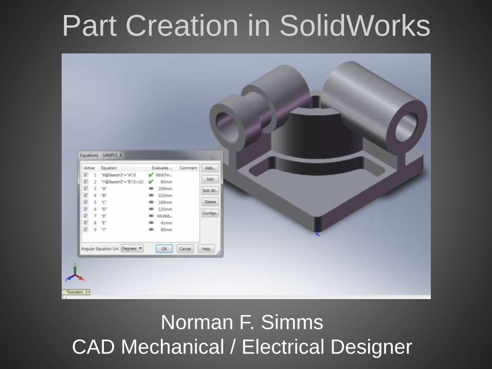
Part Creation in SolidWorks
Norman F. Simms
CAD Mechanical / Electrical Designer
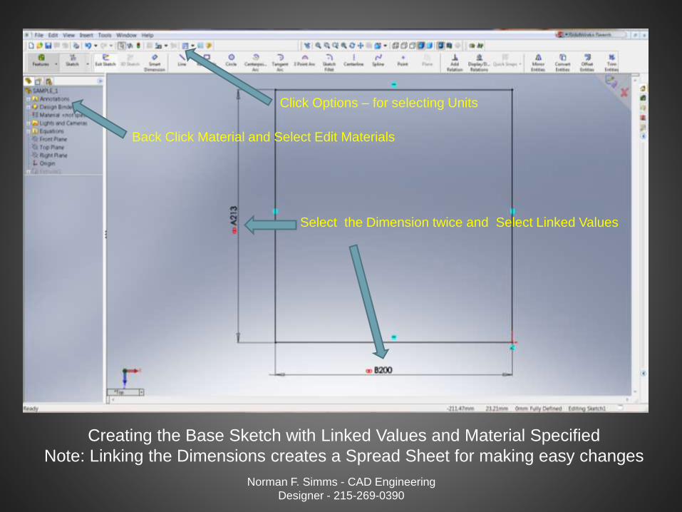
Creating the Base Sketch with Linked Values and Material Specified
Note: Linking the Dimensions creates a Spread Sheet for making easy changes
Norman F. Simms - CAD Engineering
Designer - 215-269-0390
Back Click Material and Select Edit Materials
Select the Dimension twice and Select Linked Values
Click Options – for selecting Units
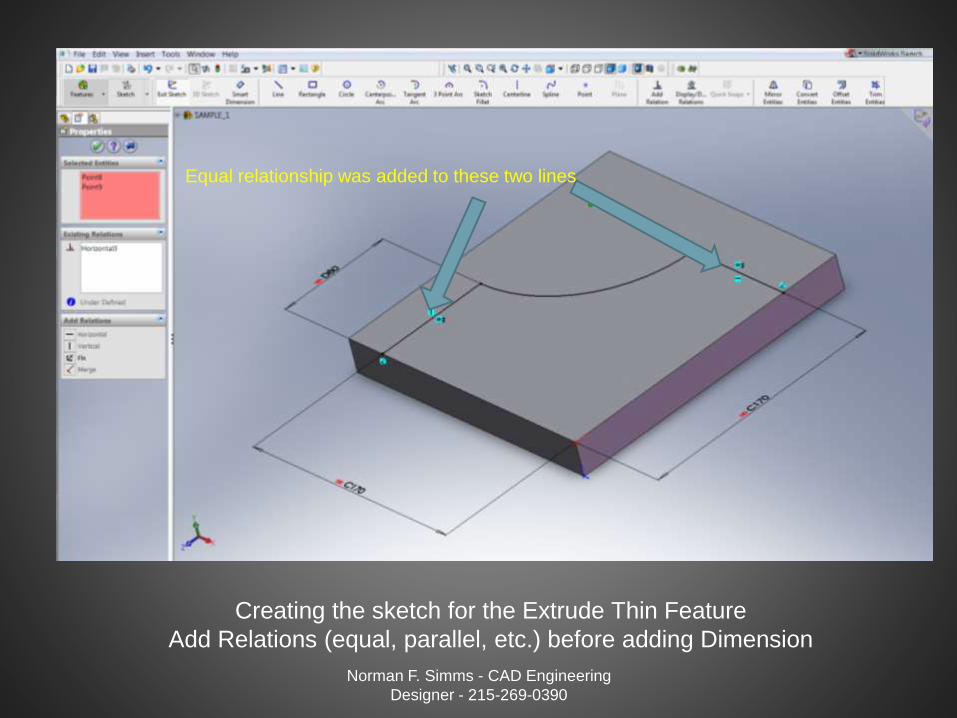
Creating the sketch for the Extrude Thin Feature
Add Relations (equal, parallel, etc.) before adding Dimension
Norman F. Simms - CAD Engineering
Designer - 215-269-0390
Equal relationship was added to these two lines

Select No to Closed Sketch on Extrude Thin Features
Norman F. Simms - CAD Engineering
Designer - 215-269-0390
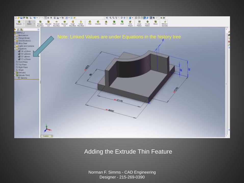
Adding the Extrude Thin Feature
Norman F. Simms - CAD Engineering
Designer - 215-269-0390
Note: Linked Values are under Equations in the history tree
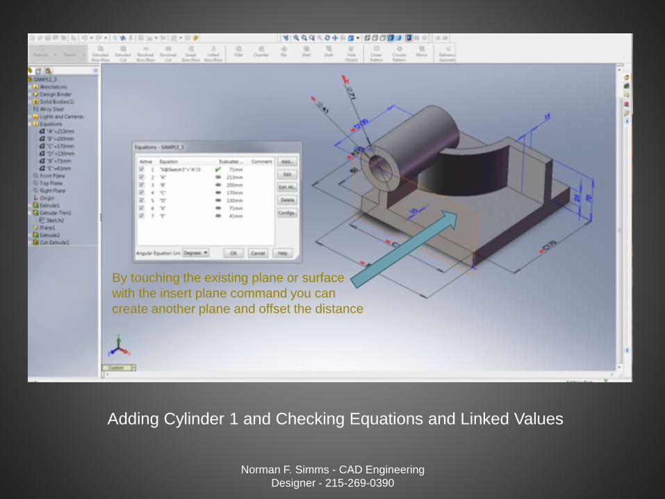
Adding Cylinder 1 and Checking Equations and Linked Values
Norman F. Simms - CAD Engineering
Designer - 215-269-0390
By touching the existing plane or surface
with the insert plane command you can
create another plane and offset the distance.
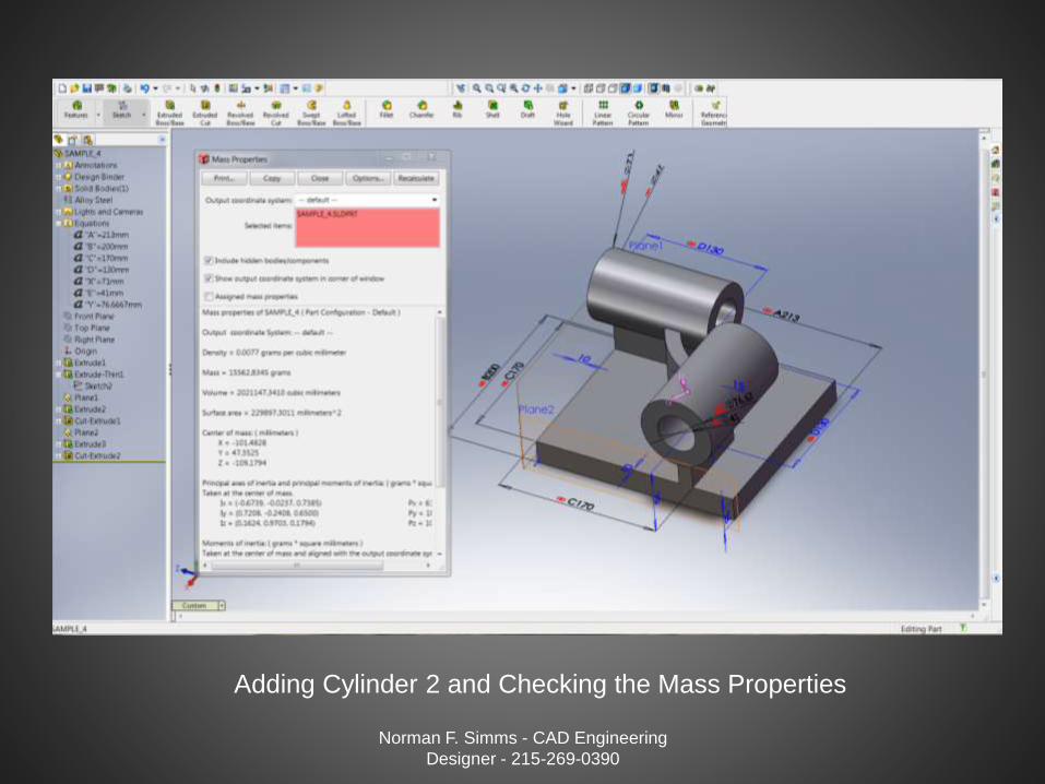
Adding Cylinder 2 and Checking the Mass Properties
Norman F. Simms - CAD Engineering
Designer - 215-269-0390

Adding Boss and Counterbore Features to the Base
Norman F. Simms - CAD Engineering
Designer - 215-269-0390
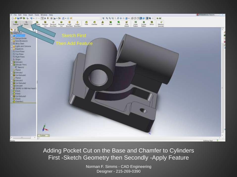
Adding Pocket Cut on the Base and Chamfer to Cylinders
First -Sketch Geometry then Secondly -Apply Feature
Norman F. Simms - CAD Engineering
Designer - 215-269-0390
Sketch First
Then Add Feature
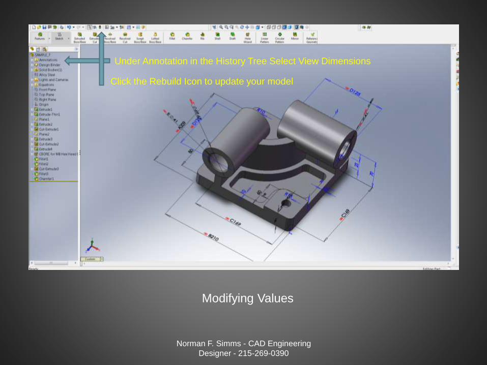
Modifying Values
Norman F. Simms - CAD Engineering
Designer - 215-269-0390
Under Annotation in the History Tree Select View Dimensions
Click the Rebuild Icon to update your model
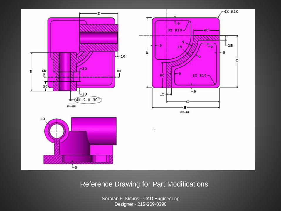
Reference Drawing for Part Modifications
Norman F. Simms - CAD Engineering
Designer - 215-269-0390
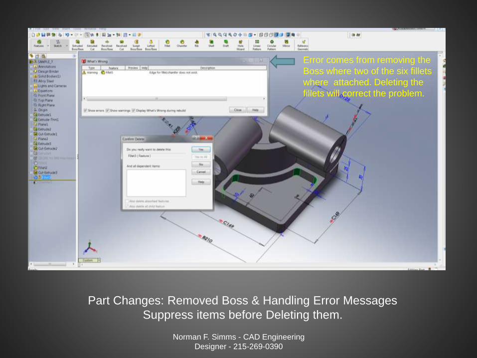
Part Changes: Removed Boss & Handling Error Messages
Suppress items before Deleting them.
Norman F. Simms - CAD Engineering
Designer - 215-269-0390
Error comes from removing the
Boss where two of the six fillets
where attached. Deleting the
fillets will correct the problem.

Added New Pocket Cut (Removed Boss Feature)
Norman F. Simms - CAD Engineering
Designer - 215-269-0390
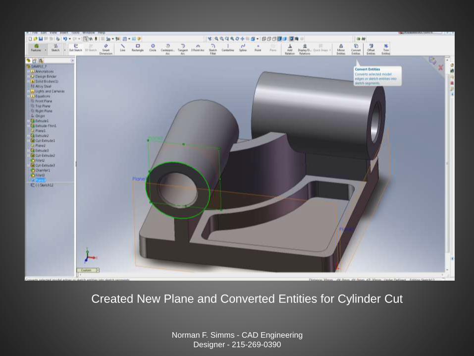
Created New Plane and Converted Entities for Cylinder Cut
Norman F. Simms - CAD Engineering
Designer - 215-269-0390

Offset Sketch Entities and Trim Unwanted Sketch
Geometry
Norman F. Simms - CAD Engineering
Designer - 215-269-0390

Created New Extruded Cut in Cylinder
Norman F. Simms - CAD Engineering
Designer - 215-269-0390
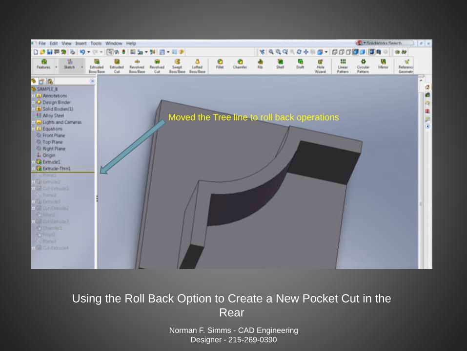
Using the Roll Back Option to Create a New Pocket Cut in the
Rear
Norman F. Simms - CAD Engineering
Designer - 215-269-0390
Moved the Tree line to roll back operations
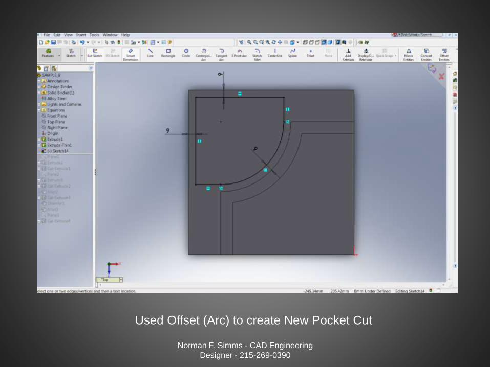
Used Offset (Arc) to create New Pocket Cut
Norman F. Simms - CAD Engineering
Designer - 215-269-0390
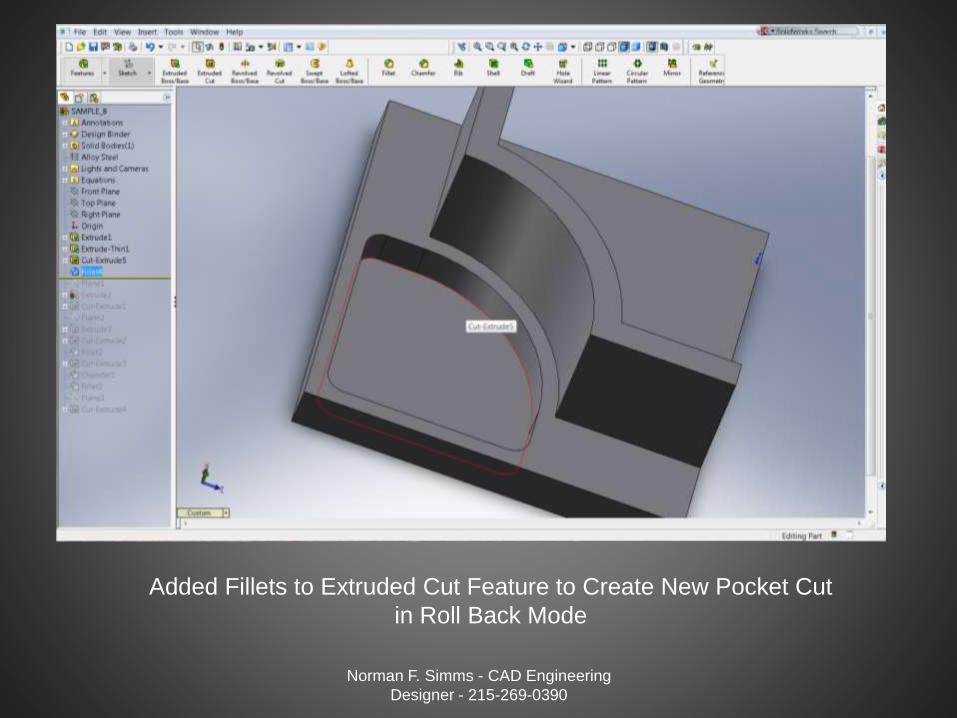
Added Fillets to Extruded Cut Feature to Create New Pocket Cut
in Roll Back Mode
Norman F. Simms - CAD Engineering
Designer - 215-269-0390
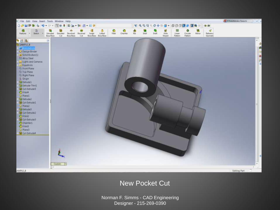
New Pocket Cut
Norman F. Simms - CAD Engineering
Designer - 215-269-0390
Norman F. Simms - CAD Engineering
Designer - 215-269-0390
Part Modeling is only a small part of understanding the many capabilities
of Computer Aided Parametric Engineering and Design but it is the
foundation of CAD technology.
If you are someone who is trying to understand CAD , I hope this was a
help.
If you are someone who need someone to help them create new design
and documentation I hope you will use the number below and give me a
call.
Thank You for Your Time.