Solid-State Memory Camcorder - Video Plus France · 4-542-447-11(1) Solid-State Memory Camcorder...
112
4-542-447-11(1) Solid-State Memory Camcorder PXW-X180 PXW-X160 Operating Guide Before operating the unit, please read this manual thoroughly and retain it for future reference. © 2014 Sony Corporation
Transcript of Solid-State Memory Camcorder - Video Plus France · 4-542-447-11(1) Solid-State Memory Camcorder...

4-542-447-11(1)
Solid-State Memory Camcorder
PXW-X180PXW-X160
Operating GuideBefore operating the unit, please read this manual thoroughly and retain it for future reference.
© 2014 Sony Corporation

2
OverviewLocation and Function of Parts ............................................... 6
Wireless Remote Commander ...................................... 14
On-Screen Indications ............................................................ 15
LCD/Viewfinder Screen ............................................... 15
PreparationsPower Supply ........................................................................... 17
Using a battery pack ..................................................... 17
Setting the Clock ..................................................................... 19
Attaching Devices .................................................................... 19
Attaching the lens hood with lens cover ...................... 19Adjusting the LCD screen and viewfinder ................... 20
Using the Wireless Remote Commander .............................. 21
Using SxS Memory Cards ...................................................... 22
About SxS memory cards ............................................. 22Inserting an SxS memory card ..................................... 22Removing an SxS memory card ................................... 22Switching between SxS memory cards ........................ 22Formatting an SxS memory card .................................. 23Checking the remaining time available for
recording ................................................................ 23
Using Other Media .................................................................. 24
XQD memory cards ..................................................... 24“Memory Stick” media/SD cards ................................. 24
Using a UTILITY SD card ..................................................... 25
Usable SD cards ........................................................... 25Inserting an SD card ..................................................... 25Removing an SD card .................................................. 25Formatting an SD card ................................................. 26Checking the Remaining Time ..................................... 26
Table of Contents

RecordingBasic Operation Procedure .................................................... 27
Adjusting the focus manually ....................................... 29Monitoring audio .......................................................... 30Cueing up ..................................................................... 30Switching the SxS memory cards ................................ 30
Changing Basic Settings ......................................................... 31
Recording format ......................................................... 31Adjusting the Image brightness .................................... 31Adjusting to natural color (White Balance) ................. 32Audio setup .................................................................. 34Time data ...................................................................... 35
Useful Functions ...................................................................... 36
Assignable buttons ....................................................... 36Slow & Quick Motion .................................................. 36Rec Review .................................................................. 37Clip Continuous Rec .................................................... 37Planning Metadata ........................................................ 38Acquiring positioning information (GPS) (PXW-X180
only) ....................................................................... 40
Proxy Recording (PXW-X180 only) .............................................................. 41
Usable SD cards ........................................................... 41Formatting an SD card ................................................. 41Checking the remaining time ....................................... 41Performing proxy recording ......................................... 41Changing the proxy recording setting .......................... 41About the recorded file ................................................. 41Storage destination of the recorded file ....................... 42About the file name ...................................................... 42
Connecting to Other Device via Wireless LAN (PXW-X180 only) ................................................................................... 42
Attaching the IFU-WLM3 ............................................ 43Connecting with the wireless LAN access point mode 43Connecting with the wireless LAN station mode ........ 45
Connecting to the Internet (PXW-X180 only) ...................... 46
Uploading a File (PXW-X180 only) ....................................... 47Preparations .................................................................. 47Selecting the file and uploading ................................... 47
Using the Wi-Fi Remote Commander (PXW-X180 only) ... 49
3

4
About the Web Menu (PXW-X180 only) .............................. 51Format settings ............................................................. 52Wireless LAN settings (Station Settings) .................... 52Upload settings ............................................................. 54Checking the file transferring (Job List) ...................... 55
Thumbnail ScreensThumbnail Screens ................................................................. 56
Configuration of the Screen ......................................... 56
Playing Clips ............................................................................ 57Playing a recorded clip ................................................. 57Playing the selected and subsequent clips in
sequence ................................................................. 57
Clip Operations ....................................................................... 57
Operations of the thumbnail menu ............................... 57Displaying the detailed information of a clip ............... 58Deleting clips ............................................................... 59Changing information on the thumbnail screen ........... 59Thumbnail Menu .......................................................... 60
Menu Configuration and Detailed SettingsOverview of the Setup menus ................................................ 61
Setup menu layers ........................................................ 61
Setup Menu Operations .......................................................... 62
Setup Menu List ...................................................................... 64
Camera menu ............................................................... 64Paint menu .................................................................... 67Audio menu .................................................................. 73Video menu .................................................................. 74LCD/VF menu .............................................................. 75TC/UB menu ................................................................ 78Recording menu ........................................................... 79Media menu .................................................................. 80File menu ...................................................................... 82System menu ................................................................ 83
External Devices ConnectionConnecting External Monitors and Recording Devices ...... 87
External Synchronization ....................................................... 88
Operating Clips with a Computer ......................................... 89Connecting with a USB Cable ..................................... 89
AppendicesImportant Notes on Operation .............................................. 91
About Recording Media ............................................... 91Special Recording and Compatible Formats ................ 92Maximum Recording Time for a Clip .......................... 92Using your Camcorder Abroad .................................... 93
Formats and Limitations of Outputs .................................... 97
Video Formats and Output Signals .............................. 97
Error/Warning Indications .................................................. 100Error Indications ......................................................... 100Warning Indications ................................................... 100Caution and Operation Confirmation Indications ...... 101
Licenses .................................................................................. 102On Accessing Software to which the GPL/
LGPL Applies ...................................................... 102Open Software Licenses ............................................. 102
Specifications ......................................................................... 102General ....................................................................... 102Lens ............................................................................ 104Camera Block ............................................................. 105Inputs/Outputs ............................................................ 105Displays ...................................................................... 106Internal Microphone ................................................... 106Media Slot Block ........................................................ 106AC adaptor ACDP-060S01 ........................................ 106Charger BC-U1 .......................................................... 106Rechargeable Battery Pack BP-U30 .......................... 107Package Configuration ............................................... 107
Index ....................................................................................... 109
5

6
Overview
For functions and usage, see the pages in parentheses.
1. Hook for shoulder strap (10)
2. REC REVIEW button
3. ASSIGN 7/FOCUS MAGNIFIER button (36)
4. (N mark) (PXW-X180 only)• Hold a NFC-compatible smartphone near
this mark when making wireless connection between the camcorder and smartphone. For details, refer to the operating instructions of the smartphone.
• NFC (Near Field Communication) is the international standard for the short range radio communication technique.
5. Accessory shoe mount
6. Microphone fixing clamper (35)
7. Microphone holder (35)
8. Multi Interface Shoe
For details about the compatible accessories with the Multi Interface Shoe, contact your dealer.
9. Remote sensor
10. Power zoom lever (28)
11. IRIS PUSH AUTO button
12. Air inlet
• Do not cover the air inlet.
13. ZOOM switch
To mount the accessory shoeMount the accessory shoe on the accessory shoe mount as illustrated.
1. Lift the edge of the accessory shoe plate and pull it in the direction opposite to that of the arrow on the accessory shoe plate and remove it from the accessory shoe.
Overview
Location and Function of Parts
Notes
Accessory shoe
Accessory shoe plate
Accessory shoe
Accessory shoe plate
Location and Function of Parts

Overview
2. Place the accessory shoe so its protrusions match recesses of the accessory shoe mount, then fix it to the mount with four screws.
3. Insert the accessory shoe plate in the direction of the arrow on the plate surface until the end of the plate engages the end of the shoe.
To remove the accessory shoeRemove the shoe plate in the same way as step 1 of “To mount the accessory shoe.” Loosen the 4 screws and remove the accessory shoe from the accessory shoe mount.
Location and Function of Parts 7

8
Overview
1. Lens (19)
2. Lens hood with lens cover (19)
3. Internal microphone (34)
4. Recording/tally lamp (84)The recording/tally lamp flashes if the remaining capacity of recording media or battery is low.
5. ASSIGN 4/ZEBRA button
6. ASSIGN 1 button
7. ASSIGN 2 button*
8. ASSIGN 3/NFC button (PXW-X180 only)
9. ASSIGN 6/VIDEO SIGNAL MONITOR button
10. FOCUS switch (29)
11. FULL AUTO button
12. CH-1 (INT MIC/EXT/MI SHOE) switch (34)
13. AUTO/MAN (CH-1) switch (34)
14. AUDIO LEVEL (CH-1) dial (34)
15. AUDIO LEVEL (CH-2) dial (34)
16. AUTO/MAN (CH-2) switch (34)
17. CH-2 (INT MIC/EXT/MI SHOE) switch (34)
18. STATUS CHECK button (11)
19. MENU button** (62)
20. SHUTTER switch
21. PUSH AUTO button (29)
22. WB SET button
23. ASSIGN 5/PEAKING button*
* The ASSIGN 5/PEAKING button and the ASSIGN 2 button have raised tactile dots for your convenience in locating the button.
** MENU button has a raised tactile bar for your convenience in locating the button.
Location and Function of Parts

Overview
1. GENLOCK/TC IN/VIDEO/TC OUT switch
2. GENLOCK/VIDEO connector (87, 99)
3. TC connector
4. SDI OUT connector (87)
5. PROXY SD slot (41)
6. AUDIO OUT connector
7. HDMI connector (87)
8. REMOTE connectorThe REMOTE connector is used for controlling start/stop of recording and other functions on the video device and peripherals connected to it.
9. Handle zoom lever (28)
10. Handle record buttonWhen the lever is set to the HOLD position, the handle record button is not operable.
11. AUDIO INPUT1 connector (34)
12. AUDIO INPUT2 connector
13. Cable holderProvided for securing a microphone cable, etc.
14. INPUT1 switch (34)
15. INPUT2 switch (34)
16. Grip belt
17. 1 (Power) switch (27)
18. Record button (27)
19. Power Lamp
20. Air outlet
• Areas around the air outlet may become hot.
• Do not cover the air outlet.
21. USB wireless LAN module retracting part (PXW-X180 only) (43)Connecting the IFU-WLM3 USB wireless LAN module (supplied) allows communication with wireless LAN devices.
22. Cable clamp partUsed for fixing cables by using a strap to protect the connector part.
• Do not use the cable clamp part for purposes other than fixing cables.
23. DC IN connector (18)
Notes
Notes
Location and Function of Parts 9

10
Overview
1. ND FILTER mode switch
2. ND FILTER switch
3. ND control dial
4. Hook for shoulder strap
5. Focus ring (29)
6. Lens cover lever (19)
7. Zoom ring (28)
8. Iris ring (31)
9. i (headphones) connectorFor stereo mini-jack headphones
10. BATT RELEASE button (17)
11. Battery pack (17)
12. Battery pack receptacle
13. UTILITY SD slot/access lamp(Used for storing and loading the settings (File function). To be supported by a future upgrade (software update).)
14. SLOT SELECT button
15. SxS memory card A slot/access lamp (22)
16. EJECT button
17. SxS memory card B slot/access lamp (22)
18. USB connector (mini-B type) (89)
19. (USB) connector (A type) (To be supported by a future upgrade.)
20. CANCEL/BACK button (62)
21. SEL/SET dial (62)
22. WHT BAL switch
23. GAIN switch (31)
24. IRIS switch
To attach a shoulder strapAttach a shoulder strap to the hooks for the shoulder strap.
Location and Function of Parts

Overview
1. OPTION button (57)
2. THUMBNAIL button (56)
3. Playback control buttons (PREV, PLAY/PAUSE*, NEXT, STOP, F REV, F FWD) (57)
4. LCD BRIGHT button (20)
5. DISPLAY button (15)
6. LCD screen (20)
7. Handle zoom switch (28)
8. Viewfinder (20)
9. Large eyecup
10. Viewfinder lens adjustment lever (20)
11. HEADPHONE MONITOR switch (35)
12. Air inlet
• Do not cover the air inlet.
13. VOLUME buttons*
14. DURATION/TC/U-BIT button (35)
15. CANCEL/BACK button (62)
16. V/v/B/b/SET buttons (62)
17. MENU button (62)
* VOLUME+ button and PLAY/PAUSE button have raised tactile dots for your convenience in locating the buttons.
Bottom
1. Tripod receptacle (1/4 inch)This receptacle is compatible with 1/4-20UNC screws.Attach a tripod (sold separately) to the tripod receptacle using a tripod screw (sold separately, the length of the screw must be less than 5.5 mm (7/32 in.)).
Status screenTo display a status screen• Press the STATUS CHECK button.
To switch status screens• Turn the SEL/SET dial.
To hide the status screen• Press the STATUS CHECK button.
Notes
Location and Function of Parts 11

12
Overview
Camera status screenDisplays the electronic shutter settings or the status of the lens.
Audio status screenDisplays the input settings for each channel, audio level meter, and wind filter setting.
System status screenDisplays the video signal settings.
Video output status screenDisplays the SDI, HDMI, and video output settings.
Assignable button status screenDisplays the function that is assigned to each assignable button.
Gain<H> Setting value of Gain <H> level
Gain<M> Setting value of Gain <M> level
Gain<L> Setting value of Gain <L> level
Preset White Preset value of white balance
ND Filter <Preset1>
Setting value of Preset1 for ND Filter
ND Filter <Preset2>
Setting value of Preset2 for ND Filter
ND Filter <Preset3>
Setting value of Preset3 for ND Filter
Gamma Gamma category and curve
AE Level Setting value of AE level
AE Speed Setting value of AE control speed
AGC Limit Setting value of the maximum gain of AGC
A.SHT Limit Fastest shutter speed of the auto shutter function
AE Mode AE mode setting (Backlight/Standard/Spotlight)
CH 1 level meter Level meter for CH 1
CH 1 Source Input source for CH 1
CH 1 Ref. / Sens. Sensitivity of the internal microphone input to CH 1, or the reference level of audio input
CH 1 Wind Filter Setting status of the wind filter for the microphone input to CH 1
CH 2 level meter Level meter for CH 2
CH 2 Source Input source for CH 2
CH 2 Ref. / Sens. Sensitivity of the internal microphone input to CH 2, or the reference level of audio input
CH 2 Wind Filter Setting status of the wind filter for the microphone input to CH 2
Audio Format Audio format setting
Headphone Out Headphone output setting
Country Setting status of the region, NTSC region or PAL region
Rec Format Recording format that is recorded on the SxS memory card
Picture Size Picture size that is recorded on the SxS memory card
Frame Rate Frame rate that is recorded on the SxS memory card
Rec Function Special recording that is set to on, and its setting value
Simul Rec On/off status of Simul Rec
Clip Continuous Rec
On/off status of Clip Continuous Rec
Video Light Set Setting status of the on/off condition of the video light
Wi-Fi (PXW-X180 only)
Setting status of wireless LAN
Proxy Recording Mode (PXW-X180 only)
Setting status of Proxy
Proxy Recording Size (PXW-X180 only)
Picture size for Proxy
SDI Output picture sizeOutput On/Off
HDMI Output picture sizeOutput On/Off
Video Output picture size
1 Function that is assigned to the Assign 1 button
2 Function that is assigned to the Assign 2 button
3 Function that is assigned to the Assign 3 button
4 Function that is assigned to the Assign 4 button
5 Function that is assigned to the Assign 5 button
6 Function that is assigned to the Assign 6 button
7 Function that is assigned to the Assign 7 button
Location and Function of Parts

Overview
Battery status screenDisplays the information of the battery or DC IN power.
Media status screenDisplays the remaining space, available recording time, and estimated service life of the recording media (SxS memory card A/SxS memory card B).
Detected Battery Battery type
Remaining Remaining charge level (%)
Charge Count Number of times that the battery is charged
Capacity Remaining capacity (Ah)
Voltage Voltage (V)
Manufacture Date
Manufacture date of the battery
Video Light Remaining
Remaining charge level of the video light battery
Power Source Power source
Supplied Voltage Supplied voltage
Media information of Media A
Media icon displayed when recording media is inserted in slot A
Protect information of Media A
Protect icon displayed when recording media inserted in slot A is write-protected
Notes
• You cannot protect the SxS memory card on the camcorder.
Remaining meter of Media A
Remaining capacity of the recording media inserted in slot A, expressed with a bar indicator
Remaining time of Media A
Estimated remaining time in minutes of the recording media inserted in slot A with the same condition
Remaining life of Media A
Remaining life in percent (%) of the media inserted in slot A when the media has its remaining life data
Media information of Media B
Media icon displayed when recording media is inserted in slot B
Protect information of Media B
Protect icon displayed when recording media inserted in slot B is write-protected
Remaining meter of Media B
Remaining capacity of the recording media inserted in slot B, expressed with a bar indicator
Remaining time of Media B
Estimated remaining time in minutes of the recording media inserted in slot B with the same condition
Remaining life of Media B
Remaining life in percent (%) of the media inserted in slot B when the media has its remaining life data
Media information of the proxy recording media (PXW-X180 only)
Media icon displayed when recording media is inserted in the PROXY SD slot
Protect information of the proxy recording media (PXW-X180 only)
Protect icon displayed when recording media inserted in the PROXY SD slot is write-protected
Remaining meter of he proxy recording media (PXW-X180 only)
Remaining capacity of the recording media inserted in the PROXY SD slot, expressed with a bar indicator
Remaining time of he proxy recording media (PXW-X180 only)
Estimated remaining time in minutes of the recording media inserted in the PROXY SD slot with the same condition
Remaining life of he proxy recording media (PXW-X180 only)
Remaining life in percent (%) of the recording media inserted in the PROXY SD slot when the media has its remaining life data
Media information of the UTILITY SD card
Media icon displayed when recording media is inserted in the UTILITY SD slot
Protect information of the UTILITY SD card
Protect icon displayed when recording media that is inserted in the UTILITY SD slot is write-protected
Remaining meter of the UTILITY SD card
Remaining capacity of the recording media inserted in the UTILITY SD slot, expressed by a bar indicator
Remaining capacity of the UTILITY SD card
Remaining capacity of the recording media inserted in the UTILITY SD slot, expressed in GB
Remaining life of the UTILITY SD card
Remaining life in percent (%) of the media inserted in the UTILITY SD slot when the media has its remaining life data
Location and Function of Parts 13

14
Overview
REC trigger setting status screenDisplays the setting status of the record button and handle record button.
1. DATA CODE buttonThis button does not work on the camcorder.
2. TC RESET button
3. SCAN/SLOW buttons
4. . > (PREV/NEXT) buttons
5. PLAY button
6. STOP button
7. DISPLAY button
8. Transmitter
9. START/STOP button
10. Power zoom lever
11. PAUSE button
12. MODE button
13. b/B/v/V/ENTER buttons
Rec Button Displays the slot for the recording target of the record button
Handle Rec Button
Displays the slot for the recording target of the handle record button
Wireless Remote Commander
Location and Function of Parts

Overview
While recording, standing by to record, or during playback, the statuses and settings of the camcorder are superimposed on the LCD/viewfinder screen.The statuses and settings of the camcorder can be turned on/off using the DISPLAY button.The statuses and settings of the camcorder can be independently turned on/off (page 76).
Information displayed on the screen while recording
1. Shutter mode/shutter speed indication
2. Gain indication (page 31)
3. ND filter indication (page 32)
4. GPS status indication (PXW-X180 only)Displays the GPS status.
5. Recording mode/slot A/B operation status indication
6. Depth of field indicationDisplays the depth of field.
7. Color temperature indication (page 32)
8. S&Q motion frame rate indication (page 79)
9. Battery remaining indication (page 17)
10. Focus position indicationDisplays focus position.
11. Zoom position indicationDisplays zoom position in the range of 0 (wide end) to 99 (tele end).
12. Iris position indicationDisplays iris position.
13. Focus macro indication
14. Focus assist indication
15. SteadyShot indication
16. Focus mode indication
17. Auto shutter indication
18. AGC indication
19. Auto iris indication
20. AE mode indication
21. White balance mode indication (page 32)
22. Rec Control status of SDI output/HDMI output indication (page 79)
23. UTILITY SD slot media status indication
24. Time data indication (page 35)
On-Screen Indications
LCD/Viewfinder Screen
zRec Recording in progress
Stby Standby for recording
ATW Automatic mode
ATW Hold Pause the automatic mode
W:P Preset mode
W:A Memory A mode
W:B Memory B mode
On-Screen Indications 15

16
Overview
25. Audio level meter
26. A/B slot media status/remaining space indication (page 23)When the left side of the icon is orange, recording is possible.When the green lamp on the upper right of the icon lights, playback is possible.
27. PROXY SD slot media status indication (PXW-X180 only)
28. VIDEO SIGNAL MONITOR indication (waveform monitor/vector scope/histogram indication)
29. Proxy status indication (PXW-X180 only)
30. Wireless LAN connection status indication (PXW-X180 only) (page 42)Displays the status when the wireless LAN function is on.
31. Audio format indication
32. TC IN connection status indication (page 78)Displays the status when the timecode is input from an external device.
33. Gamma indication (page 68)Displays the gamma setting value.
34. Recording format (codec) indication (page 31)Displays the format that is recorded on an SxS memory card.
35. System frequency and scan method indication
36. Recording format (picture size) indication (page 31)Displays the picture size that is recorded on an SxS memory card.
Information displayed on the playback screenThe following information is superimposed on the playback screen.
1. Clip no./total number of clips
2. Playback mode
3. Playback format (picture size)
4. Battery remaining
5. Playback format (frame rate)
6. Time dataThe time data is displayed when the unit status/settings are displayed by pressing the DISPLAY button, and “Timecode” in “Display On/Off” of the LCD/VF menu is set to “On.”
7. Audio levelsThe audio levels for the recording are displayed.
8. MediaA mark appears to the left if the memory card is write-protected.
9. Playback format (codec)
On-Screen Indications

Preparations
You can use a battery pack or AC power via an AC adaptor.For safety, use only the Sony battery packs and AC adaptor listed below:
Lithium-ion Battery PackBP-U30BP-U60BP-U60TBP-U90
ChargerBC-U1BC-U2
AC Adaptor (supplied)ACDP-060S01
Notes
The BC-U1/BC-U2 Charger cannot be used as the external power source device for the camcorder.When connecting the camcorder to the wall outlet (wall socket), use the supplied AC adaptor.
Fully insert the battery pack into the battery pack receptacle (page 10), then slide it down to lock it.To remove the battery pack, press and hold the BATT RELEASE button (page 10), slide the battery pack upward to unlock it, then pull it out.
Notes
• Before use, charge the battery pack with the supplied BC-U1 or BC-U2 Charger.
• A warm battery pack immediately after use may not be able to be fully recharged.
• The high-capacity BP-U90 Battery Pack is large, and protrudes from the camcorder when attached. When using the camcorder with the BP-U90 attached for extended recording periods, Sony recommends attaching the camcorder to a tripod for convenience.
Checking battery charge remainingWhen recording or playback is in progress on the battery pack, an icon to show the current battery charge level and usage time remaining are displayed on the LCD/viewfinder screen (page 15).
The camcorder indicates the remaining usage time in minutes by calculating the available time with the battery pack if operation is continued at the current rate of power consumption.
If the battery charge remaining becomes lowIf the battery charge remaining decreases to a certain level during operation (Low BATT status), a low-battery message, flashing of the recording/tally lamp, and a beep sound will warn you.If the battery charge remaining further decreases to a level at which operation cannot be continued (BATT Empty status), a battery-empty message appears.Replace the battery pack with one that is fully charged.
To change the message levelsThe Low BATT level is set to 10% of full charge, and the BATT Empty level is set to 3% of full charge at the factory. These settings can be changed with “Battery Alarm” (page 86) in the System menu.
Preparations
Power Supply
Using a battery pack
Icon Remaining
100% to 91%
90% to 71%
70% to 51%
50% to 31%
30% to 11%
10% to 0%
Power Supply 17

18
Preparations
Using a wall outlet (wall socket) as a power sourceYou can use the AC Adaptor to obtain AC power.
1. Connect the power cord (mains lead) to the AC Adaptor.
2. Connect the AC Adaptor to the DC IN connector of the camcorder.
3. Connect the power cord (mains lead) to the wall outlet (wall socket).
On the AC Adaptor• Use a nearby wall outlet (wall socket) when
using the AC Adaptor. Disconnect the AC Adaptor from the wall outlet (wall socket) immediately if any malfunction occurs while using your camcorder.
• Do not use the AC Adaptor placed in a narrow space, such as between a wall and furniture.
• Do not short-circuit the plug of the AC Adaptor with any metallic objects. This may cause a malfunction.
• Even if your camcorder is turned off, AC power (house current) is still supplied to it while
connected to the wall outlet (wall socket) via the AC Adaptor.
• You cannot charge the camcorder by connecting it to the AC Adaptor.
Power cord (mains lead)
To the wall outlet (wall socket)
DC IN connector
AC Adaptor ACDP-060S01
Power Supply

Preparations
When you turn the camcorder on for the first time after purchasing or the backup battery has completely discharged, the Initial Setting display appears on the viewfinder screen and LCD screen. Set the date and time of the built-in clock, using this display.
Time ZoneThe value shows the time difference from UTC (Coordinated Universal Time). Change the setting if needed.
Setting the time and dateThe clock starts after you turn the SEL/SET dial (page 10) to select an item or value, then press the SEL/SET dial to set it.
After the setting display disappears, “Clock Set” (page 85) of the System menu can be used to set “Time Zone” and date/time.
Notes
• If the clock setting is cleared because the backup battery fully discharged when no power was supplied (no battery pack and no DC IN connection), the Initial Setting display will be displayed when you next turn the camcorder on.
• While the Initial Setting display is shown, no other operation, except turning the power off, is permitted until you finish the setting for this display.
Align the marks on the lens hood to those on the camcorder, and turn the lens hood in the direction of the arrow 2 until it is locked.
Opening or closing the shutter of the lens hood with lens coverMove the lens cover lever to OPEN to open the lens cover, and move the lever to CLOSE to close the lens cover.
Removing the lens hood with lens coverTurn the lens hood in the opposite direction of the arrow 2 in the illustration while pressing the PUSH (lens hood release) button.
Notes
• Remove the lens hood with lens cover when you attach/detach a 82mm polarized filter or protective filter.
Setting the Clock Attaching Devices
Attaching the lens hood with lens cover
PUSH (lens hood release) button
Setting the Clock / Attaching Devices 19

20
Preparations
LCD screenOpen the LCD screen 180 degrees (1), then rotate it to the best angle to record or play back (2).
• Images are displayed as mirror images on the LCD screen, but are recorded as normal images.
• You can switch the brightness of the backlight of the LCD screen with the LCD BRIGHT button (page 11).
ViewfinderLook through the viewfinder with the LCD screen closed when using the viewfinder.If the viewfinder screen display is not clear, adjust by using the lens adjustment lever below the viewfinder.
You can switch the brightness of the viewfinder with “Brightness” in “VF Setting” of the LCD/VF menu (page 75).
Adjusting the LCD screen and viewfinder
1Open 180 degrees.
2180 degrees (max.)
290 degrees (max.)
Viewfinder lens adjustment leverMove it until the picture becomes clear.
Attaching Devices

Preparations
Before useBefore you use the supplied Wireless Remote Commander for the first time, pull out the insulation sheet from the battery holder.
A CR2025 lithium battery is set in the holder at the factory.
Using the Wireless Remote CommanderFor controlling the camcorder from the Wireless Remote Commander, activate the remote control function of the camcorder after turning the power on.Activating/deactivating the remote control function can be achieved using the Setup menu.
To activate using the menuPress the MENU button to set the camcorder to Menu mode, then set “IR Remote” (page 86) of the System menu to “On.”
Notes
• Aim the Wireless Remote Commander towards the remote sensor to operate your camcorder.
• Point the remote sensor away from strong light sources such as direct sunlight or overhead lighting. Otherwise, the Wireless Remote Commander may not function properly.
• When you are operating with the Wireless Remote Commander supplied with your camcorder, your video device may also operate. In that case, select a commander mode other than DVD2 for your video device, or cover the sensor of your video device with black paper.
Replacing the battery in the Wireless Remote CommanderUse a commercially available CR2025 lithium battery. Do not use any battery other than a CR2025.
1. While pressing on the tab, inset your fingernail into the slit to pull out the battery case.
2. Place a new battery with the + side facing up.
3. Insert the battery case back into the Wireless Remote Commander until it clicks.
• Danger of explosion if battery is incorrectly replaced. Replace only with the same or equivalent type recommended by the manufacturer.When you dispose of the battery, you must obey the law in the relative area or country.
• When the lithium battery becomes weak, the operating distance of the Wireless Remote Commander may shorten, or the Wireless Remote Commander may not function properly. In this case, replace the battery with a Sony CR2025 lithium battery. Use of another battery may present a risk of fire or explosion.
Using the Wireless Remote Commander
Insulation sheet
CAUTION
Tab
• Battery may explode if mistreated.Do not recharge, disassemble, or dispose of in fire.
• Batteries shall not be exposed to excessive heat such as sunshine, fire or the like.
WARNING
Using the Wireless Remote Commander 21

22
Preparations
This camcorder records audio and video on SxS memory cards (sold separately) inserted in the card slots.
Notes
• If the video format is set to AVCHD, an SxS memory card cannot be used. Use “Memory Stick” media or an SD card (page 24).
Usable SxS memory cardsUse the following Sony SxS memory cards.Operations are not guaranteed with memory cards other than the following cards.
SxS PRO+ series
SxS PRO series
SxS-1 series
These cards comply with the ExpressCard standard.
For details on using SxS memory cards and usage-related precautions, refer to the instruction manual for the SxS memory card.
SxS, SxS PRO and SxS-1 are trademarks of Sony Corporation.The ExpressCard word mark and logo are owned by Personal Computer Memory Card International Association (PCMCIA) and are licensed to Sony Corporation. All other trademarks are the property of their respective owners.
Notes
• An SxS memory card that is formatted in UDF cannot be used on the camcorder.
1 Open the cover of the card slot block.
2 Insert the SxS memory card with the SxS label facing to the right.
The access lamp (page 10) lights in red, then changes to green once the memory card is ready for use.
3 Close the cover.
Notes
• If you insert a memory card into the slot in the wrong direction, the memory card, the memory card slot, or image data may be damaged.
1 Open the cover of the card slot block, then pull the EJECT button out by pressing it.
2 Press the EJECT button to remove the SxS memory card.
Notes
• Data integrity is not guaranteed if the power is turned off or a memory card is removed while it is being accessed. Data on the card may be destroyed. Be sure that its access lamp is lit in green or off when you turn off the power or remove a memory card.
• An SxS memory card removed from the camcorder after recording ended may be hot. This is not a malfunction.
When SxS memory cards are loaded in both card slots A and B, press the SLOT SELECT button (page 10) to select the card you wish to use.If a card becomes full during recording, switching to the other card is automatically executed.
Notes
• The SLOT SELECT button is disabled while playback is in progress. Switching is not executed even if you press the button. The button is enabled while the thumbnail screen is displayed (page 56).
Using SxS Memory Cards
About SxS memory cards
Inserting an SxS memory card
Removing an SxS memory card
Switching between SxS memory cards
Using SxS Memory Cards

Preparations
If an SxS memory card is not formatted, or was formatted with another system, the message “Media Needs to be Formatted” is displayed on the LCD/viewfinder screen.Format the card as follows.
Using “Format Media” (page 80) of the Media menu, specify “Media(A)” (slot A) or “Media(B)” (slot B), then select “Execute.” On the confirmation message, select “Execute” again.
The in-progress message is displayed, and the access lamp lights in red.When formatting is complete, a completion message is displayed. Press the SEL/SET dial to hide the message.
If formatting failsA write-protected SxS memory card or memory card that cannot be used with this camcorder will not be formatted.If a warning message is displayed, replace the card with an appropriate SxS memory card, according to the instructions in the message.
Notes
• All the data, including recorded pictures and setup files, are erased when a memory card is formatted.
While recording (or standing by to record), you can check the remaining space for the SxS memory cards loaded in the card slots on the A/B slot media status/remaining space indication of the LCD/viewfinder screen (page 15).The available time for recording with the current video format (recording bit rate) is calculated according to the remaining space of each card and displayed in time units of minutes.
Notes
• A icon appears if the memory card is write-protected.
Replacing an SxS memory card• If the available time on two cards in total
becomes less than 5 minutes, the warning message “Media Near Full” is displayed, the recording/tally lamp flashes, and a beep sound is output to the headphones to warn you. Replace the cards with those that have sufficient space.
• If you continue recording until the total remaining time reaches zero, the message changes to “Media Full,” and recording stops.
Notes
• Up to approximately 600 clips can be recorded on one SxS memory card.If the number of recorded clips reaches the limit, the remaining time indication becomes “0,” and the message “Media Full” is displayed.
Formatting an SxS memory card
Checking the remaining time available for recording
Using SxS Memory Cards 23

24
Preparations
By using the QDA-EX1 Media Adaptor (supplied with PXW-X180 NTSC model only), you can insert an XQD memory card into the SxS memory card slot and use it instead of an SxS memory card.
Usable XQD memory cardsXQD memory card S seriesXQD memory card H seriesXQD memory card N series
For details on using a QDA-EX1 Media Adaptor, refer to the instruction manual supplied with it.
Notes
• High-speed playback (page 57) may not be properly achieved with an XQD memory card.
• Not all XQD memory cards are guaranteed to work with this camcorder. For compatible memory cards, contact your dealer.
• If the video format is set to AVCHD, an XQD memory card cannot be used. Use “Memory Stick” media or an SD card (page 24).
FormattingWhen you use an XQD memory card with this camcorder, formatting is required.An XQD memory card to be used with this camcorder must be formatted using the format function of this camcorder.It is also necessary to format an XQD memory card for use if a caution message is displayed when you mount the XQD memory card.For an XQD memory card that was formatted with another system unsupported by this camcorder, the message “Unsupported File System” is displayed on the LCD/viewfinder screen.Format the XQD memory card as instructed below.
To execute formatting
Using “Format Media” (page 80) of the Media menu, specify “Media(A)” (slot A) or “Media(B)” (slot B), then select “Execute.”
An in-progress message is displayed, and the access lamp lights in red.
When formatting is completed, a completion message is displayed for three seconds.
Notes
• When formatting, all data in an XQD memory card, including protected images, is erased and cannot be restored.
To use media formatted with this camcorder in the slots of other devicesMake a backup of the media, then format it using the other device.
Use of the MEAD-MS01 Media Adaptor (sold separately) or MEAD-SD02 Media Adaptor (supplied with PXW-X180 of other than the NTSC model and PXW-X160) permits you to insert a “Memory Stick” or an SD card to the SxS memory card slot and use it for recording and playback in the same way as with an SxS memory card.
Usable “Memory Stick”“Memory Stick PRO-HG Duo”“Memory Stick XC-HG Duo”
Usable SD cardSDHC card (SD speed class: Class 10)SDXC card (SD speed class: Class 10)
For details on use of the MEAD-MS01/SD02 Media Adaptor, refer to the operating instructions supplied with the respective adaptor.
Notes
• High-speed playback (page 57) may not be properly achieved with a “Memory Stick” or an SD card.
• Not all “Memory Stick” or SD card are guaranteed for operation. About memory cards that have been verified for operation, contact the dealer.
• Slow & Quick Motion recording (page 36) cannot be made with a “Memory Stick” or an SD card.
FormattingWhen you use a “Memory Stick” or an SD card with this camcorder, formatting is required. A “Memory Stick” or an SD card to be used with this camcorder must be formatted using the format function of this camcorder.It is also necessary to format a “Memory Stick” or an SD card for use if a caution message is displayed when you mount the “Memory Stick” or SD card.
Using Other Media
XQD memory cards
“Memory Stick” media/SD cards
Using Other Media

Preparations
For a “Memory Stick” or an SD card that was formatted with another system unsupported by this camcorder, the message “Unsupported File System” is displayed on the LCD/viewfinder screen.Format the “Memory Stick” or SD card as instructed below.
To execute formatting
Using “Format Media” (page 80) of the Media menu, specify “Media(A)” (slot A) or “Media(B)” (slot B), then select “Execute.”
An in-progress message is displayed, and the access lamp lights in red.When formatting is completed, a completion message is displayed for three seconds.
Notes
• When formatting, all data in a “Memory Stick” or an SD card, including protected images, is erased and cannot be restored.
To use media formatted with this camcorder in the slots of other devicesMake a backup of the media, then format it using the other device.
You can store the setting value file of the camera on an SD card (sold separately). The stored file can be loaded from the SD card.
SDHC memory card* (Speed Class: 4 to 10, UHS is not compatible, Capacity: 2 GB to 32 GB)SD memory card* (Capacity: up to 2 GB)* Indicated as “SD card” in this Operating Guide.
1 Open the cover of the UTILITY SD slot (page 10).
2 Insert the UTILITY SD card into the slot with the UTILITY SD label facing right.
The access lamp (page 10) lights in red, then turns off when the memory card is ready for use.
3 Close the cover.
Open the cover of the UTILITY SD slot (page 10), remove the SD card by pressing the SD card once lightly.
Notes
• Data integrity is not guaranteed if the power is turned off or a memory card is removed while it is being accessed. Data on the card may be destroyed. Be sure that its access lamp is off before you turn off the power or remove a memory card.
• Make sure that the card does not pop out when inserting or removing it.
Using a UTILITY SD card
Usable SD cards
Inserting an SD card
Removing an SD card
Using a UTILITY SD card 25

26
Preparations
When you use an SD card with this camcorder, it must be formatted using the format function of this camcorder.It is also necessary to format an SD card if a caution message is displayed when you mount it.
Using “Format Media” (page 80) in the Media menu, specify “SD Card” then select “Execute.” On the confirmation message, select “Execute” again.
The in-progress message and status bar are displayed, and the access lamp lights in red.When formatting is complete, a completion message is displayed. Press the SEL/SET dial to hide the message.
Notes
• All the data is erased when a memory card is formatted, and the data cannot be restored.
The remaining time can be checked on the media status screen (page 13).
Notes
• A icon appears if the memory card is write-protected.
To use media formatted with this camcorder in the slots of other devicesMake a backup of the media, then format it using the other device.
Formatting an SD card
Checking the Remaining Time
Using a UTILITY SD card

Recording
Basic recording can be performed with the following procedures.
1 Make sure that the necessary devices are attached to the camcorder and power is supplied to them.
2 Load the memory card(s).
If you load two SxS memory cards, recording is continued by automatically switching to the second card when the first card becomes full.
3 Open the cover of the lens hood with lens cover.
4 Slide the power switch to on while pressing the green button.
The recording screen is displayed on the LCD/viewfinder screen.
5 Press the record button (page 9).
The recording/tally lamp lights and recording begins.
6 To stop recording, press the record button again.
Recording stops and the camcorder enters STBY (recording standby) mode.
Recording (Full Auto mode)Press the FULL AUTO button so that the button indicator lights.Full Auto mode is turned on, the TLCS (Total Level Control System) (page 65) is activated, Auto Iris, AGC (Auto Gain Control), and Auto Shutter, and ATW (Auto-Tracing White balance) are set to on. Then, the brightness and white balance will be automatically adjusted.When you wish to adjust them manually, turn Full Auto mode off.
Shooting without suspending while changing an memory card (Relay Recording)When SxS memory cards are loaded in both slot A and slot B, the camcorder switches automatically to the other card if the selected card becomes full during recording.
Notes
• Do not remove the memory card that is recording. Remove only the memory card in the slot whose access lamp is turned off during recording.
• If the recordable memory card is loaded into the other slot when the remaining time of the memory card that is recording is less than 1 minute, the message “Will Switch Slots Soon” is displayed. It goes out when the slot is switched.
• The relay recording function may not work if you start recording when the remaining time of the memory card is less than 1 minute. To perform the relay recording properly, make sure that the remaining time of the memory card is more than 1 minute.
• The video that is recorded by using the relay recording function on the camcorder cannot be played seemlessly on the camcorder.
• To combine the videos that are recorded by using the relay recording function, use the “Content Browser” software.
Recording on memory card A and memory card B simultaneously (Simultaneously Recording)You can perform simultaneously recording by using memory cards in both the memory card A and memory card B slot.
Set “Setting” in “Simul Rec” of the Recording menu to “On.”
Notes
• The simultaneously recording function cannot be used during Slow & Quick Motion mode (page 36) or Clip Continuous Rec mode (page 37).
• There is a limit to selectable recording formats when simultaneously recording images to an SD card and “Memory Stick.” For details, see page 91.
Recording
Basic Operation Procedure
Basic Operation Procedure 27

28
Recording
Changing the setting of the record button and handle record buttonYou can start/stop recording on the memory card in each slot independently by using the record button and handle record button.The default setting starts/stops recording on memory card A and memory card B simultaneously by using either of the buttons.• Rec Button:
Handle Rec Button:
To change the setting
Select “Rec Button Set” in “Simul Rec” of the Recording menu.
Adjusting the zoom
To use the power zoom lever
1. Set the ZOOM switch E to SERVO.
2. Zoom by pressing the power zoom lever D.Lightly press the power zoom lever D for a slower zoom. Fully press it for a faster zoom.
• The minimum distance required between your camcorder and the subject for focus is about 1 cm (about 13/32 in.) for wide angle and about 80 cm (about 2 5/8 feet) for telephoto.
• The focus may not be adjusted at certain zoom positions if the subject is within 80 cm (about 2 5/8 feet) from your camcorder.
• When “Focus Macro” in “Focus” of the Camera menu is set to “Off,” you cannot focus on a subject within 80 cm (about 2 5/8 feet) regardless of the zoom position (page 65).
• Be sure to keep your finger on the power zoom lever D. If you move your finger off the power zoom lever D, the operation sound of the power zoom lever D may also be recorded.
• You can change the zoom speed (normal/fast) of the power zoom lever D or the handle zoom lever A on “Setting” in “Speed Zoom” of the Camera menu (page 66).
To use the handle zoom
1. Set the handle zoom switch B to VAR or FIX.• When you set the handle zoom switch B
to VAR, you can zoom in or out at a variable speed.
• When you set the handle zoom switch B to FIX, you can zoom in or out at a fixed speed, which is set in “Setting” in “Handle Zoom” of the Camera menu (page 66).
2. Press the handle zoom lever A to zoom in or out.
Notes
• You cannot use the handle zoom lever A when the handle zoom switch B is set to OFF.
• You cannot change the zoom speed of the power zoom lever D with the handle zoom switch B.
To use the zoom ring
1. Set the ZOOM switch E to MANUAL.
2. Zoom by turning the zoom ring C.
“Rec Button Set” setting
Operation
Rec Button:
Handle Rec Button:
Starts/stops recording on memory card A and memory card B simultaneously by using either of the buttons.
Rec Button:
Handle Rec
Button:
Starts/stops recording on memory card A by using the record button, and memory card B by using the handle record button.
Rec Button:
Handle Rec
Button:
Starts/stops recording on the memory card B by using the record button, and memory card A by using the handle record button.
Close view: (Telephoto)
Wide view: (Wide angle)
Basic Operation Procedure

Recording
You can zoom at the desired speed by turning the zoom ring C. Fine adjustment is also possible.
Notes
• Turn the zoom ring C at a moderate speed. If you turn it too fast, the zoom speed may lag behind the zoom ring rotation speed, or the operation sound of the zoom may also be recorded.
You can adjust the focus manually for different recording conditions. Use this function in the following cases.
—To record a subject behind a window covered with raindrops.
—To record horizontal stripes.—To record a subject with little contrast
between the subject and its background.—When you want to focus on a subject in the
background.
—To record a stationary subject using a tripod.
Adjusting focus manually in Full MF modeIn Full MF mode, you can manually adjust focus without automatic adjustment functions.Set the focus ring A to the Full MF mode position and focus manually using the focus scale on the lens.
Notes
• Turn the focus ring slowly. If it is forced against either end, the focus ring may move toward the AF/MF mode position and move past the end, and make noise.
• While in Full MF mode, the auto focus and push auto focus function does not work.
• While in Full MF mode, macro is set to off regardless of the “Focus Macro” setting in “Focus” of the Camera menu.
Adjusting focus manually in AF/MF modeIn mode B, you can use the automatic adjustment functions during manual focus adjustment. Set the focus ring to the AF/MF mode position and do the following steps.
1. Set the FOCUS switch B to MAN.
2. Turn the focus ring to adjust the focus.
For focusing manually• It is easier to focus on the subject when you use
the zoom function. Move the power zoom lever towards T (telephoto) and adjust the focus, then, towards W (wide angle) to adjust the zoom for recording.
• When you want to record a close-up image of a subject, move the power zoom lever towards W (wide angle) to fully magnify the image, then adjust the focus.
To restore automatic adjustmentSet the FOCUS switch B to AUTO. The focus mode indication changes to “AF” and the automatic focus adjustment is restored.
To use automatic focus temporarily(Push auto focus)Record the subject while pressing and holding the PUSH AUTO button C.If you release the button, the setting returns to manual focusing.Use this function to shift the focus on one subject to another during the manual focus mode.
Adjusting the focus manually
AF/MF mode
Full MF mode
Basic Operation Procedure 29

30
Recording
Using the focus magnifier (Focus Magnifier)In the default setting, “Focus Magnifier” is assigned to the ASSIGN 7 button (page 36).Press the ASSIGN 7 button.The focus magnifier screen appears and the center of the screen is magnified by about 2.0 times. It will be easier to confirm the focus setting during manual focusing. The screen returns to the original size when you press the button again.
Notes
• Even though the image appears expanded on the screen, the recorded image is not expanded.
In normal playback mode, you can monitor the recorded audio signals through the connected headphones.You can select the audio channel to be monitored and adjust the sound volume by using the HEADPHONE MONITOR switch and VOLUME buttons.
To start playback from the top of the clipPress the PREV button or NEXT button of the playback control buttons (page 11). You can cue to the top of a desired clip by pressing either button repeatedly.
When two memory cards are loaded, press the SLOT SELECT button (page 10) to switch memory cards.
Notes
• You cannot switch SxS memory cards during playback.Continuous playback of cards in slots A and B is not possible.
Monitoring audio
Cueing up
Switching the SxS memory cards
Clip (recording data)When you stop recording, video, audio, and subsidiary data from the start to end of the recording are recorded as a single clip on an SxS memory card.
Clip nameFor each clip recorded with this camcorder, a clip is named by the naming mode that is set in “Clip” (page 81) of the Media menu.
Maximum duration of a clipThe maximum clip length differs depending on the recording format.The maximum continuous recording time for a movie is same as it for a clip. If recording time reaches the maximum continuous recording time, the recording will stop.For details about the maximum recording time of a clip for the recording format, see “Maximum Recording Time for a Clip” (page 92).
Basic Operation Procedure

Recording
You can make changes to the settings based on the intended usage of the recorded video or recording conditions.
Selectable format depends on the setting of the region where the camcorder is used (Country) or the codec (Codec).To change the format, use “Video Format” in “Rec Format” (page 83) of the System menu.
You can adjust the image brightness by adjusting the iris, gain, or shutter speed, or by reducing the light volume with ND FILTER.
Adjusting the iris (Auto mode)Adjust the brightness according to the subject.When Full Auto mode (page 27) is set to on:Iris is forcibly set to Auto mode.When Full Auto mode is set to off:Set the IRIS switch F to AUTO. The Auto Iris mode is set.You can select the target level (to make the picture darker or brighter) for Auto Iris via the Setup menu. (The gain control in AGC mode and the shutter speed control in Auto Shutter mode are adjusted in synchronization.)
To adjust the target level with the Setup menuSet “Level” in “Auto Exposure” (page 65) of the Camera menu.
Adjusting the iris (Manual mode)If Full Auto mode is set to off, set the IRIS switch F to MANUAL. The Manual Iris mode is set. Rotate the iris ring D for the desired iris opening.
Adjusting the gainYou can adjust the gain manually when you do not want to use the AGC (automatic gain control).
1. Set Full Auto mode to off.
2. When the gain is automatically adjusted, set “AGC” in “Auto Exposure” of the Camera menu (page 65) to “Off.”“AGC” disappears.
3. Set the GAIN switch G to H, M or L.The gain value set for the selected gain switch position appears on the screen. You can set the gain value for H/M/L from “Gain” of the Camera menu (page 64).
To adjust the gain automaticallySet “AGC” in “Auto Exposure” of the Camera menu (page 65) to “On.”The gain value disappears, and “AGC” appears.
Notes
• When you set Full Auto mode to on, other manually adjusted items (iris, shutter speed, white balance) also become automatic.
Changing Basic Settings
Recording format
Adjusting the Image brightness
Changing Basic Settings 31

32
Recording
Shooting with a fixed shutterSet the shutter speed (cache time).When you set the SHUTTER switch E to ON, the fixed shutter is turned on in the mode and with the shutter speed you specified with “Shutter” (page 66) of the Camera menu.
Notes
• When “Auto Shutter” in “Auto Exposure” (page 65) of the Camera menu is set to “On,” the fixed shutter cannot be selected. Set “Auto Shutter” to “Off.”
Setting with the Camera menuThe shutter mode and shutter speed can be set with “Shutter” (page 66) of the Camera menu.
Shooting in slow shutter (SLS) modeThe shutter speed is specified in the number of accumulated frames. Up to 16 frames can be accumulated in this mode, permitting you to obtain low-noise clear pictures in low light levels or surreal pictures with afterimages.Select “Shutter” (page 66) of the Camera menu and set the number of accumulated frames with “SLS Frame.”
Shooting in Auto Shutter modeThe shutter speed is automatically adjusted according to the picture brightness.When you set the camcorder to Full Auto mode (page 27), Auto Shutter is forcibly selected.When Full Auto mode is off, you can independently turn Auto Shutter mode on by setting “Auto Shutter” in “Auto Exposure” (page 65) of the Camera menu to “On.”
Adjusting the volume of light (ND filter)You can record a subject with the proper brightness by using the ND FILTER switch B when the recording environment is too bright.The camcorder has two ND filter modes. You can switch the mode by using the ND FILTER mode switch A.
Preset modeSet the ND FILTER mode switch A to PRESET, then set the ND FILTER switch B to the following.CLEAR: ND filter is not used.
1: Filter level that is set with “Preset1” in “ND Filter” of the Camera menu. The default setting is 1/4.2: Filter level that is set with “Preset2” in “ND Filter” of the Camera menu. The default setting is 1/16.3: Filter level that is set with “Preset3” in “ND Filter” of the Camera menu. The default setting is 1/64.
Variable modeSet the ND FILTER mode switch A to VARIABLE, then set the ND FILTER switch B to the following.CLEAR: ND filter is not used.1, 2, 3: You can set the filter level from 1/4 to 1/128 continuously by using the ND control dial C.The ND FILTER switch B position (1/2/3) does not affect the filter level adjustment.
You can select the adjustment mode according to the shooting conditions.
Preset modeThe color temperature is adjusted to the preset value (factory setting: 3200K) in this mode. Select this mode when there is no time to adjust the white balance or when you wish to fix the white balance that is set with “Preset White” in “White” of the Paint menu (page 67).
Adjusting to natural color (White Balance)
Changing Basic Settings
Recording
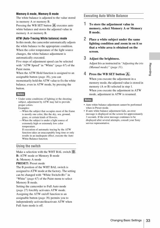
Memory A mode, Memory B modeThe white balance is adjusted to the value stored in memory A or memory B.Pressing the WB SET button A executes auto white balance and stores the adjusted value in memory A or memory B.
ATW (Auto-Tracing White balance) modeIn this mode, the camcorder automatically adjusts the white balance to the appropriate condition.When the color temperature of the light source changes, the white balance adjustment is automatically executed.Five steps of adjustment speed can be selected with “ATW Speed” in “White” (page 67) of the Paint menu.When the ATW Hold function is assigned to an assignable button (page 36), you can momentarily hold the ATW value to fix the white balance, even in ATW mode, by pressing the button.
Notes
• Under some conditions of lighting or the shooting subject, adjustment by ATW may fail to provide proper colors.Examples:—When the subject that occupies most of the frame
is mostly one color, like the sky, sea, ground, grass, or certain kinds of flowers.
—When the subject is under a light source of extremely high or extremely low color temperature.If execution of automatic tracing by the ATW function takes an unacceptably long time or only results in an inadequate effect, execute the Auto White Balance function.
Using the switchMake a selection with the WHT BAL switch B.B: ATW mode or Memory B modeA: Memory A modePRESET: Preset modeThe B position of the WHT BAL switch is assigned to ATW mode at the factory. The setting can be changed with “White Switch<B>” in “White” (page 67) of the Paint menu to select Memory B mode.Setting the camcorder to Full Auto mode (page 27) forcibly activates ATW mode.Assigning the ATW on/off function to an assignable button (page 36) permits you to independently activate/deactivate ATW when Full Auto mode is off.
Executing Auto White Balance
1 To store the adjustment value in memory, select Memory A or Memory B mode.
2 Place a white subject under the same lighting condition and zoom in on it so that a white area is obtained on the screen.
3 Adjust the brightness.
Adjust Iris as instructed in “Adjusting the iris (Manual mode)” (page 31).
4 Press the WB SET button A.
When you execute the adjustment in a memory mode, the adjusted value is stored in memory (A or B) selected in step 1.When you execute the adjustment in ATW mode, adjustment in ATW is resumed.
Notes
• Auto white balance adjustment cannot be performed when in Preset mode.
• If auto white balance adjustment fails, an error message is displayed on the screen for approximately 3 seconds. If the error message continues to be displayed after several attempts, consult your Sony service representative.
Changing Basic Settings 33

34
Recording
The following connectors, switches and dials allow you to set the sound to be recorded.
External audio input connectors and switchesAUDIO INPUT1 connector AAUDIO INPUT2 connector BINPUT1 switch DINPUT2 switch C
Audio source switchesCH-1 (INT MIC/EXT/MI SHOE) switch ECH-2 (INT MIC/EXT/MI SHOE) switch J
Recording level controlsAUTO/MAN (CH-1) switch FAUTO/MAN (CH-2) switch IAUDIO LEVEL (CH-1) dial GAUDIO LEVEL (CH-2) dial H
Using the internal microphoneThe sound will be recorded in stereo when using the internal microphone. To adjust the input volume of the internal microphone, perform the following steps.
1. Set the CH-1 (INT MIC/EXT/MI SHOE) switch E and CH-2 (INT MIC/EXT/MI SHOE) switch J to INT MIC.The left and right channels can be controlled together by using the CH-1 switch and dial for setting the recording level.
2. Set the AUTO/MAN (CH-1) switch F of the channel to be adjusted to MAN.
appears on the screen.
3. Adjust the microphone volume by turning the AUDIO LEVEL (CH-1) dial G of the channel to be adjusted during recording or standby.
To return to auto level adjustingSet the AUTO/MAN (CH-1) switch F of the channel that is adjusted manually to AUTO.• If the recording level is low, set “INT MIC
Sensitivity” in “Audio Input” of the Audio menu to “High” (page 73).
• To reduce wind roar, set “INT MIC Wind Filter” in “Audio Input” of the Audio menu to “On” (page 73).
Recording sound via an external microphone or audio deviceECM-673 Electret Condenser Microphone or other devices can be connected and used for recording.
1. Select the input source.Set the INPUT1/INPUT2 switch according to the devices connected to the AUDIO INPUT1/AUDIO INPUT2 connector.
• If you connect a device that does not support +48V phantom power, a
Audio setup
Audio devices Switch position
External audio device (mixer, etc.)
LINE
Dynamic microphones or microphones with a built-in battery
MIC
+48V power (Phantom power) microphone
MIC+48V
Changing Basic Settings

Recording
malfunction may result from setting this switch to MIC+48V. Check before connecting the device.
• When there is no audio device connected to an input connector, set the INPUT1/INPUT2 switch of that connector to LINE to prevent noise.
To record by using an external microphone
1. Open the cover by pulling the handle of the microphone fixing clamper/microphone holder.
2. Attach a microphone, then fix it by closing the cover of the microphone fixing clamper/microphone holder.
3. Connect the microphone cable to the AUDIO INPUT1/AUDIO INPUT2 connector (A/B).
4. Set the CH-1 (INT MIC/EXT/MI SHOE) switch E and CH-2 (INT MIC/EXT/MI SHOE) switch J to EXT.When “INPUT CH Select” in “Audio Input” of the Audio menu is set to “INPUT1/INPUT2,” the sound from the AUDIO INPUT1 connector will be recorded on CH-1 and the sound from the AUDIO INPUT2 connector will be recorded on CH-2.When “INPUT CH Select” is set to “INPUT1/INPUT1,” the sound from the AUDIO INPUT1 connector will be recorded on both CH-1 and CH-2.
5. Set the INPUT1/INPUT2 switch.
6. Set the input level of the microphone.
• Set the input level of the microphone with “INPUT1 Reference/INPUT2 Reference” in “Audio Input” of the Audio menu (page 73). Adjust according to the sensitivity of the microphone.
• When you use a stereo microphone (2 XLR plugs), connect the L (left) channel plug to the AUDIO INPUT1 connector, and the R (right) channel plug to the AUDIO INPUT2 connector. Set the CH-1 (INT MIC/EXT/MI SHOE) and CH-2 (INT MIC/EXT/MI SHOE) switches to EXT.
Setting the headphone sound
You can select the channel to output from the headphone by setting the HEADPHONE MONITOR switch to CH-1 or CH-2, to output from the headphone.See “Headphone Out” in “Audio Output” of Audio menu for details about the sound when set to STEREO MIX (page 73).
Setting the timecodeSpecify the timecode to be recorded with “Timecode” in the TC/UB menu (page 78).
Displaying the time dataPressing the DISPLAY button displays the time data on the screen (page 15).The indication is switched among the timecode, user bits, and recording duration each time you press the DURATION/TC/U-BIT button (page 11).
Time data
Display ContentsTCG **:**:**:** Timecode
CLK **:**:**:** Timecode (Clock mode)
UBG ** ** ** ** User bits
DUR **:**:** Duration from the beginning of recording
Changing Basic Settings 35

36
Recording
The camcorder has seven assignable buttons (pages 6, 8) to which you can assign various functions for convenience.
Changing functionsUse “Assignable Button” (page 84) in the System menu.The assigned functions can be viewed on the assignable button status screen (page 12).
Default assigned functions Button 1 OffButton 2 OffButton 3 NFC (PXW-X180) / Off (PXW-X160)Button 4 ZebraButton 5 PeakingButton 6 Video Signal MonitorButton 7 Focus Magnifier
Assignable functions• Off• Marker (page 75)• Zebra (page 76)• Peaking (page 75)• Video Signal Monitor (page 84)• Focus Magnifier (page 30)• Focus Macro (page 65)• VF Mode (page 84)• Auto Exposure Level (page 65)• Spotlight (page 84)• Backlight (page 84)• ATW (page 33)• ATW Hold (page 33)• SteadyShot (page 66)• Color Bars (page 66)• NFC (PXW-X180 only)• Rec Lamp (page 84)• Rec Review (page 37)• Thumbnail (page 60)• Shot Mark1 (page 84)• Shot Mark2 (page 84)• Clip Flag OK (page 84)• Clip Flag NG (page 84)• Clip Flag Keep (page 84)
When the video format (page 31) is set to the following settings, you can set the recording frame rate and playback frame rate to different values.XAVC-L 1920 × 1080/59.94p, 29.97p,
23.98p, 50p, 25p1280 × 720/59.94p, 50p
XAVC-I 1920 × 1080/29.97p, 23.98p, 25p1280 × 720/59.94p, 50p
MPEG HD422 1920 × 1080/29.97p, 23.98p, 25p1280 × 720/59.94p, 29.97p, 23.98p, 50p, 25p
Notes
• Slow & Quick Motion mode cannot be used while recording, playing, or displaying thumbnails.
• Audio cannot be recorded while in Slow & Quick Motion mode.
• If you record at a frame rate faster than 60 fps at a resolution of 720, the following will occur.—The imaging field becomes narrower than usual.—Automatic focus is not available.—Focus assist indication, depth of field indication,
focus position indication, iris position indication, and zoom position indication are set to OFF.
Useful Functions
Assignable buttons
Slow & Quick Motion
Format Resolution Frame rateXAVC-L 1080 1 to 60 fps
(59.94p, 29.97p, 23.98p, 50p, 25p)
720 1 to 120 fps(59.94p, 50p)
XAVC-I 1080 1 to 60 fps(29.97p, 23.98p, 25p)
720 1 to 60 fps(59.94p, 50p)
MPEG HD422
1080 1 to 30 fps(29.97p, 23.98p, 25p)
720 1 to 60 fps(59.94p, 29.97p, 23.98p, 50p, 25p)
Useful Functions

Recording
You can review the last recorded clip on the screen (Rec Review).
Press the REC REVIEW button (page 6) after you stop recording.
You can use an assignable button (page 36) by assigning the Rec Review function to an assignable button.Rec Review stops at the end of the clip, then resumes the STBY (recording standby) status.
To stop Rec ReviewPress the REC REVIEW button, STOP button, or assignable button assigned to the Rec Review function.
Notes
• The playback control buttons other than the record button do not work during the Rec Review playback.
• Rec Review does not work when changing the video format after recording.
• The Setup menus cannot be operated during Rec Review.
Normally, a clip is created as an independent file each time you start and stop recording. However, this function allows you to start and stop recording while continuously recording to the same clip, for as long as the function remains enabled. This is convenient when you do not want to generate a large number of short clips, and when you want to record without worrying about exceeding the clip limit. It is still easy to find recording start points, because a Rec Start mark is recorded at the recording start point each time you start recording.For details about the recording format that is compatible with Clip Continuous Rec, see “Special Recording and Compatible Formats” (page 92).
Settings before shootingPerform the setting with “Clip Continuous Rec” (page 79) of the Recording menu in advance.The Clip Continuous Rec function is enabled and “Cont” appears on the screen (page 15) by setting “Setting” to “On.”
Notes
• The Clip Continuous Rec function cannot be used at the same time as the Slow & Quick Motion function.
When you set Clip Continuous Rec to on, the Slow & Quick Motion function is disabled.
• The Clip Continuous Rec function cannot be set to on during recording.
To shoot in Clip Continuous Rec modeStart the recording after completing the required setting.
Press the record button.
When recording starts, the “Cont” indication on the screen changes to the “zRec” indication (z is red).
Notes
• During recording or in recording standby mode (when the “Cont” indication is lit), if you remove the SxS memory card, the battery, or the power source, the SxS memory card needs to be restored. Exit Clip Continuous Rec mode and then remove the SxS memory card. When the “Cont” indication is flashing (at 1 flash/s), you can remove the SxS memory card.
• Stop the recording after the recording continues for two or more seconds.
To exit Clip Continuous Rec modeWith the camcorder in recording standby mode, set “Setting” in “Clip Continuous Rec” (page 79) of the Recording menu to “Off.”
LimitationsA single continuous clip cannot be created if you perform one of the following operations while the camcorder is recording or in recording standby mode. A new clip will be created when you next start recording.• Operate on a clip (lock, delete, or rename a clip)• Change the memory card slot• Change the recording format• Turn the camcorder off by setting the power
switch to off• Display the thumbnail screen• Play a clip• Stop the Clip Continuous Rec mode
Rec Review
Clip Continuous Rec
Useful Functions 37

38
Recording
Planning metadata is information about shooting and recording plans, recorded in an XML file.
Example of a planning metadata file
You can shoot using clip names and shot mark names defined in advance in a planning metadata file.This camcorder can display clip names and shot mark names defined in the following languages:• Japanese• English • Chinese • German • French• Italian • Spanish • Dutch• Portuguese • Swedish • Norwegian • Danish • Finnish
Notes
• If you define clip and shot mark names in languages other than those listed above, they may not be displayed on the LCD/viewfinder screen.
• If you define clip and shot mark names in French, Dutch, or Finnish, some characters are displayed in a different but similar font.
Loading a Planning Metadata fileTo record planning metadata together with clips, it is necessary to load a planning metadata file into the camcorder’s memory in advance.
Notes
• The Planning metadata cannot be loaded from an SDXC card.
To use an SxS memory cardInsert the SxS memory card with the planning metadata file (.xml) saved to the directory below into the camcorder’s card slot, then select and load the file via “Load Media(A)” or “Load Media(B)” in “Planning Metadata” (page 82) of the File menu./XDROOT/General/Sony/Planning
Confirming the detailed information in planning metadata After loading a planning metadata file into memory of the camcorder, you can check the details of the file, such as the filename, time and date of file creation, and the titles specified in the file. Select “Properties” in “Planning Metadata” (page 82) of the File menu, then select “Execute.”
Clearing the loaded planning metadataTo clear the planning data loaded in the camcorder’s memory, proceed as follows:Select “Clear Memory” in “Planning Metadata” (page 82) of the File menu, then select “Execute.”
Defining a clip name in Planning MetadataThe following two types of clip name strings can be written in a planning metadata file.• ASCII-format name, which is displayed on the
viewfinder screen • UTF-8-format name, which is actually
registered as the clip name
When you specify a clip name in planning metadata, the name is displayed under the operation status indication on the viewfinder screen.
Example of clip name stringsUse a text editor to modify the description for the <Title> tag.The shaded fields in the example are clip name strings. “Typhoon” is described in ASCII-format (up to 44 characters). “Typhoon_Strikes_Tokyo” is described in UTF-8-format (up to 44 bytes). Here, “sp” indicates a space, and 3 indicates a carriage return.
<?xmlspversion="1.0"spencoding="UTF-8"?>3
Planning Metadata
Useful Functions
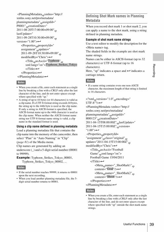
Recording
<PlanningMetadataspxmlns="http://xmlns.sony.net/pro/metadata/planningmetadata"spassignId="P0001"spcreationDate="2011-08-20T17:00:00+09:00"splastUpdate="2011-09-28T10:30:00+09:00"spversion="1.00">3
<PropertiessppropertyId="assignment"spupdate="2011-09-28T10:30:00+09:00"spmodifiedBy="Chris">3
<TitlespusAscii=" "spxml:lang="en"></Title>3
</Properties>3
</PlanningMetadata>3
Notes
• When you create a file, enter each statement as a single line by breaking a line with a CRLF only after the last character of the line, and do not enter spaces except where specified with “sp.”
• A string of up to 44 bytes (or 44 characters) is valid as a clip name. If a UTF-8-format string exceeds 44 bytes, the string up to the 44th byte is used as the clip name. If only a string in ASCII-format is specified, the ASCII-format name up to the 44th character is used as the clip name. When neither the ASCII-format name string nor UTF-8-format name string is valid, a clip name in the standard format is used.
Using a clip name defined in planning metadata Load a planning metadata file that contains the clip name into the memory of the camcorder, then select “Plan” in “Auto Naming” in “Clip” (page 81) of the Media menu.Clip names are generated by adding an underscore (_) and a 5-digit serial number (00001 to 99999).Example: Typhoon_Strikes_Tokyo_00001,
Typhoon_Strikes_Tokyo_00002, ...
Notes
• If the serial number reaches 99999, it returns to 00001 upon the next recording.
• When you load another planning metadata file, the 5-digit serial number returns to 00001.
Defining Shot Mark names in Planning MetadataWhen you record shot mark 1 or shot mark 2, you can apply a name to the shot mark, using a string defined in planning metadata.
Example of shot mark name stringsUse a text editor to modify the description for the <Meta name> tag.The shaded fields in the example are shot mark name strings.Names can be either in ASCII-format (up to 32 characters) or UTF-8-format (up to 16 characters).Here, “sp” indicates a space and 3 indicates a carriage return.
Notes
• If a name string contains even one non-ASCII character, the maximum length of that string is limited to 16 characters.
<?xmlspversion="1.0"spencoding="UTF-8"?>3
<PlanningMetadata xmlns="http://xmlns.sony.net/pro/metadata/ planningmetadata"spassignId=" H00123"spcreationDate=" 2011-04-15T08:00:00Z"splastUpdate="2011-04-15T15:00:00Z"spversion="1.00">3
<PropertiessppropertyId="assignment"spclass="original"spupdate="2011-04-15T15:00:00Z"spmodifiedBy="Chris">3
<TitlespusAscii="Football Game"spxml:lang="en">Football Game 15/04/2011</Title>3
<Metaspname="_ShotMark1"spcontent=" "/>3
<Metaspname="_ShotMark2"spcontent=" "/>3
</Properties>3
</PlanningMetadata>3
Notes
• When you create a file, enter each statement as a single line by breaking a line with a CRLF only after the last character of the line, and do not enter spaces except where specified with “sp” outside the shot mark name strings.
TyphoonTyphoon_Strikes_Tokyo
Goal
Shoot
Useful Functions 39

40
Recording
1. Press the MENU button during standby.
2. Set “GPS” of the System menu to “On.” appears and the camcorder prepares for
acquiring positioning.The positioning information is recorded while recording video when acquiring positioning.
Notes
• The icon that is displayed on the screen changes depending on the reception status of the signals from the satellite.
• In the default setting, “GPS” is set to “On.” When “GPS” is set to “On,” location information and positioning time of the video that is recorded are also recorded. To record positioning information, set “GPS” to “On.”
• It may take time to start positioning after turning the camcorder on.
• If the icon does not indicate the positioning status after several minutes, the GPS signal reception status is poor. Move to a place with a clear view of the sky. If recording starts in that
status, positioning information cannot be recorded.
• The GPS signal may not be received well indoors or near a tall building. Move to a place with a clear view of the sky.
• Even though the icon indicates positioning, the GPS information recording may cut off depending on the signal reception status.
Acquiring positioning information (GPS) (PXW-X180 only)
Positioning status
Display GPS reception status
Off Not displayed
GPS is set to off or an error occurs.
Difficult to acquire positioning
Positioning information cannot be acquired because the GPS signal cannot be received.Move to a place with a clear view of the sky.
Detecting the satellite
The camcorder is detecting the satellite. It may takes several minutes to acquire positioning.
Positioning Weak GPS signal is being received.
GPS signal is being received. Positioning information can be acquired.
Strong GPS signal is being received. Positioning information can be acquired.
Useful Functions

Recording
You can record proxy data on an SD card simultaneously while recording on an SxS memory card.
SDHC memory card* (Speed Class: Higher than 4, Capacity: Up to 32 GB)* Indicated as “SD card” in this Operating Guide.
When you use an SD card with this camcorder, it must be formatted using the format function of this camcorder.It is also necessary to format an SD card if a caution message is displayed when you mount it.
Using “Format Media” (page 80) in the Media menu, specify “Proxy” then select “Execute.” On the confirmation message, select “Execute” again.
The in-progress message and status bar are displayed, and the access lamp lights in red.When formatting is complete, a completion message is displayed. Press the SEL/SET dial to hide the message.
Notes
• All the data is erased when an SD card is formatted, and the data cannot be restored.
The remaining time can be checked on the media status screen (page 13).
Notes
• A icon appears if the SD card is write-protected.
To use media formatted with this camcorder in the slots of other devicesMake a backup of the media, then format it using the other device.
1 Set “Setting” in “Proxy Recording Mode” of the Recording menu to “On.”
2 Open the cover of the PROXY SD (page 9).
3 Insert the SD card into the slot with the label facing right.
The access lamp (page 9) lights in red, then turns off when the memory card is ready for use.
4 Close the cover.
5 Start recording.
When the recording on an SxS memory card is stopped, proxy recording is also stopped.
Notes
• Data integrity is not guaranteed if the power is turned off or an SD card is removed while it is being accessed. Data on the SD card may be destroyed. Be sure that its access lamp is off before you turn off the power or remove an SD card.
• Make sure that the SD card does not pop out when inserting or removing it.
Setting the picture sizeSelect the picture size with “Size” in “Proxy Recording Mode” of the Recording menu.
Checking the frame rateCheck the frame rate with “Frame Rate” in “Proxy Recording Mode” of the Recording menu.
Checking the bit rateCheck the bit rate with “Bit Rate” in “Proxy Recording Mode” of the Recording menu.
The file system of the recorded file is FAT32, and the file extension is “.mp4.”The timecode is also recorded simultaneously.
Proxy Recording (PXW-X180 only)
Usable SD cards
Formatting an SD card
Checking the remaining time
Performing proxy recording
Changing the proxy recording setting
About the recorded file
Proxy Recording (PXW-X180 only) 41

42
Recording
The recorded file is stored under the “/PRIVATE/PXROOT/Clip” directory.
The file name is automatically generated as “a character string that is set on the Setup menu” + serial number.• Number of characters is 1 to 46. Usable
characters are as follows.—Alphabet (A to Z, a to z), Numerals (0 to 9),
Symbols (! # $ % ( ) + , - . ; = @ [ ] ^ _ ~ (space))
• The serial number is kept even if the camcorder is turned off. The serial number returns to 0001 by performing All Reset.
You can make a wireless LAN connection between the camcorder and a device such as a smartphone or tablet by attaching the supplied IFU-WLM3 USB wireless LAN module.
Notes
• You cannot use a USB wireless LAN module other than the IFU-WLM3.
Making a wireless LAN connection between a device and the camcorder enables you to do the following.• Remote operation via a wireless LAN
You can control the camcorder from a smartphone, tablet, or computer that is connected to the camcorder via the wireless LAN.
• File transferring via a wireless LANYou can transfer a proxy file (low resolution) that is recorded on an SD card in the camcorder or original file (high resolution) that is recorded by the camcorder to the server via the wireless LAN.
• Video/audio streaming via a wireless LANYou can create a stream (H.264/AAC-LC compression) from the video/audio of a camcorder, and watch the video/audio streaming by using the “Content Browser Mobile” application that is installed on a smartphone, tablet, or computer via the wireless LAN.
“Content Browser Mobile” applicationYou can operate the camcorder remotely while streaming the audio/video of the camcorder, and perform the settings of the camcorder by using the “Content Browser Mobile” application.
For details about the “Content Browser Mobile” application, contact your Sony dealer or a Sony service representative.
Storage destination of the recorded file
About the file name
Connecting to Other Device via Wireless LAN (PXW-X180 only)
Connecting to Other Device via Wireless LAN (PXW-X180 only)

Recording
Compatible devicesYou can use a smartphone, tablet, or computer for setting and operating the camcorder. Compatible devices, operating systems, and browsers are as follows.
1 Open the cover of the USB wireless LAN module retracting part (page 9).
2 Insert the IFU-WLM3 to the USB connector.
3 Close the cover.
Notes
• Attach/remove the IFU-WLM3 while the camcorder is turned off.
The camcorder works as an access point, and connects to a device via a wireless LAN.
Connecting to an NFC-compatible device with one-touch operationYou can connect the camcorder to an NFC-compatible device with one-touch operation by using the NFC function.
1 Start “Settings” on the device, select “Other Settings,” then mark the “NFC” checkbox.
2 Turn the camcorder on.
3 Activate the NFC function.
Set the camcorder to the NFC connection mode by pressing and holding the ASSIGN 3/NFC button (for 3 seconds), or activate “NFC” in “Wi-Fi” of the System menu. The NFC function is available while appears on the screen.
Device OS BrowserSmartphone Android 4.3 Chrome
iOS 7 Safari
Tablet Android 4.3 Chrome
iOS 7 Safari
Computer Microsoft Windows 7/Microsoft Windows 8
Chrome
Mac OS 10.8/10.9
Safari
Attaching the IFU-WLM3
Connecting with the wireless LAN access point mode
Smartphone/tablet
Computer
Connecting to Other Device via Wireless LAN (PXW-X180 only) 43

44
Recording
Notes
• It may take a time (for 30 to 60 seconds) until appears on the screen. Wait until the flashing “AP” indication for the wireless LAN connection status on the LCD/viewfinder screen (page 16) is turned on.
4 Hold the smartphone near the camcorder.
The smartphone is connected to the camcorder and “Content Browser Mobile” starts.
Notes
• Cancel the sleep or screen lock function of the smartphone in advance.
• Hold the device near to the camcorder without moving the device until “Content Browser Mobile” starts (1 to 2 seconds).
Connecting to a WPS-compatible deviceYou can connect the camcorder to a WPS-compatible device by using the WPS function.
1 Set the camcorder’s wireless LAN operation mode to the access point mode by setting “Setting” in “Wi-Fi” of the System menu to “Access Point.”
Notes
• It may take a time (for 30 to 60 seconds) until the camcorder is in the access point mode. Wait until the flashing “AP” indication for the wireless LAN connection status on the LCD/viewfinder screen (page 16) is turned on.
2 Activate “WPS” in “Wi-Fi” of the System menu.
3 Select “Network Setting” > “Wi-Fi Setting” on the device, then set “Wi-Fi” to on.
4 Select the camcorder’s SSID from the SSID list in “Wi-Fi Network” on the device, then select “WPS Push Button” in “Option” on the device.
Notes
• The operation method differs depending on the device.
5 Start the browser on the device, then access “http://192.168.1.1:8080/index.html.”
The screen for inputting “User Name” and “Password” appears.
6 Input the user name and password, then select “OK.”
For the user name and password of the access authentication, check “Basic Authentication” of the System menu (page 85).
Connecting by inputting an SSID and password on a deviceYou can connect the camcorder to a device by inputting an SSID and password on a device.
1 Set the camcorder’s wireless LAN operation mode to the access point mode by setting “Setting” in “Wi-Fi” of the System menu to “Access Point.”
Notes
• It may take time (for 30 to 60 seconds) until the camcorder is in the access point mode. Wait until the flashing “AP” indication for the wireless LAN connection status on the LCD/viewfinder screen (page 16) is turned on.
2 Select “Network Setting” > “Wi-Fi Setting” on the device, then set “Wi-Fi” to on.
3 Connect the device to the camcorder by selecting the camcorder’s SSID from the SSID list in “Wi-Fi Network” and inputting the password on the device.
For the SSID and password of the camcorder, check “SSID & Password” in “Wi-Fi” of the System menu (page 85).
Connecting to Other Device via Wireless LAN (PXW-X180 only)

Recording
Notes
• The operation method differs depending on the device.
4 Start the browser on the device, then access “http://192.168.1.1:8080/index.html.”
The screen for inputting “User Name” and “Password” appears.
5 Input the user name and password, then select “OK.”
For the user name and password of the access authentication, check “Basic Authentication” of the System menu (page 85).
The camcorder connects to an existing access point of the wireless LAN as a client. The camcorder and device connect via the access point.
Connecting to the access point with the WPS functionIf the access point is compatible with the WPS function, you can connect to the access point with simple settings. If the access point is not compatible with the WPS function, see “To connect to the access point in the station mode without the WPS function” (page 53).
1 Turn the access point on.
2 Turn the camcorder on.
3 Set the camcorder’s wireless LAN operation mode to the station mode by setting “Setting” in “Wi-Fi” of the System menu to “Station.”
Notes
• It may take a time (for 30 to 60 seconds) until the camcorder is in the station mode. Wait until the flashing signal status indication for the wireless LAN connection status on the LCD/viewfinder screen (page 16) is turned on.
4 Activate “WPS” in “Wi-Fi” of the System menu.
5 Press the WPS button of the access point.
For the operation of the WPS button, refer to the operating instructions of the access point.When the connection is completed, the signal status indication for the wireless LAN connection status (page 16) lights at a strength of more than 1.
Notes
• If the connection fails, perform steps from step 1 again.
6 Connect the device to the access point.
For connecting, refer to the operating instructions of the device.
7 Start the browser on the device, then access to “http://<IP address that the access point assigns to the camcorder>:8080/index.html.”
For the camcorder’s IP address, check “IP Address” in “Wi-Fi” of the System menu.The screen for inputting “User Name” and “Password” appears.
Connecting with the wireless LAN station mode
Smartphone/tablet
Computer
Access point
Connecting to Other Device via Wireless LAN (PXW-X180 only) 45

46
Recording
8 Input the user name and password, then select “OK.”
The Web menu of the camcorder appears on the browser. For details, see “About the Web Menu (PXW-X180 only)” (page 51).For the user name and password of the access authentication, check “Basic Authentication” of the System menu (page 85). You can connect the camcorder to the Internet via
an optional 3G/4G/LTE access point or by tethering to a device.
Connecting to the Internet in the wireless LAN station modeYou can connect the camcorder to the Internet in the station mode via the optional 3G/4G/LTE access point or by tethering to a smartphone or tablet.
Connecting to the Internet (PXW-X180 only)
Smartphone/tablet
Computer
Access point
Internet
Connecting to the Internet (PXW-X180 only)

Recording
ConnectingIf the access point or device is compatible with the WPS function, connect the camcorder to the Internet by performing procedures of “Connecting to the access point with the WPS function” (page 45). If the access point or device is not compatible with the WPS function, connect the camcorder to the Internet by performing procedures of “To connect to the access point in the station mode without the WPS function” (page 53).Before connecting, turn the access point or device on, and activate its tethering function.
You can upload a proxy file or original file that is recorded on the camcorder to the server on the Internet via a 3G/4G/LTE line or access point.
To connect to the InternetConnect the camcorder to the Internet by following the procedure of “Connecting to the Internet (PXW-X180 only)” (page 46).
To register the server for uploadingRegister the server for uploading in advance.For details about registering the server, see “Register the server for uploading” (page 54).
Upload the file that is recorded on an SD card, or the original file that is recorded on an SxS memory card, to the server.
Uploading a proxy file on an SD card
1 Connect a device to the camcorder via a wireless LAN, start the browser on the device, then access the camcorder from the browser (page 42).
2 Display the file list screen to select the file.
Touch “ ” > “Media Info” > “SD Card.”The “SD Card,” “Slot A,” or “Slot B” screen appears.Example: “SD Card” screen
Smartphone/tablet
Internet
Uploading a File (PXW-X180 only)
Preparations
Selecting the file and uploading
Uploading a File (PXW-X180 only) 47

48
Recording
3 Select the file.
Select the file by touching the file. To cancel, touch the file again.You can check the file by double touching the file to play back (SD card only).
4 Touch “Transfer.”
The server that you set to the default server at “Default Server” in “Register the server for uploading” (page 54) appears.To change the server, touch the server to display the server list, then select a server.Input the directory for the server to “Directory” if necessary.
5 Touch “Transfer.”
The camcorder starts uploading the selected file.To cancel uploading, touch “Cancel.”
Uploading an original file on an SxS memory card
1 Connect a device to the camcorder via a wireless LAN, start the browser on the terminal device, then access the camcorder from the browser (page 42).
2 Display the file list screen to select the file.
Perform “File Transfer” in “File Transfer” of the System menu to change the camcorder to the dedicated mode for uploading the original file.Touch “ ” > “Media Info” > “Slot A” (for a memory card in the slot A) or “Slot B” (for a memory card in the slot B).The “SD Card,” “Slot A,” or “Slot B” screen appears.
Example: “SD Card” screen
3 Select the file.
Select the file by touching the file. To cancel, touch the file again.You can check the file by double touching the file to play back (SD card only).
4 Touch “Transfer.”
The server that you set to the default server at “Default Server” in “Register the server for uploading” (page 54) appears.To change the server, touch a server to display the server list, then select the server.Input the directory for the server to “Directory” if necessary.
5 Touch “Transfer.”
The camcorder starts uploading the selected file.To cancel uploading, touch “Cancel.”
Checking the file uploadingYou can check the upload status on the “Job List” screen that is displayed by touching “Job List” on the “SD Card,” “Slot A,” or “Slot B” screen (page 55).
Uploading a File (PXW-X180 only)

Recording
When a wireless LAN connection is established between a device, such as smartphone, tablet, and the camcorder, the Wi-Fi remote commander appears on the device screen and the device can be used as a remote commander. You can start/stop recording and adjust the recording settings with a Wi-Fi connected device. This function is useful for setting the camcorder in a remote place, such as the top of a crane, etc.
Wi-Fi remote commander displays
Smartphone
Main screen
Playback screen
Cursor screen
Assign screen
Using the Wi-Fi Remote Commander (PXW-X180 only)
• Recording settings indication:S&Q FPS, Shutter, Preset White, Gamma, Auto Iris, Auto Shutter, AGC, ATW, Color Bars, Auto White
• Status indication• Playback operation
button:F Rev, Play/Pause, F Fwd, Prev, Stop, Next
• Status indication• Cursor operation
button, menu/status indication:Up, Left, Set, Right, Down, Cancel/Back, Menu, Status
• Status indication• Assignable button
indication:Assignable buttons 1 to 7
Using the Wi-Fi Remote Commander (PXW-X180 only) 49

50
Recording
Tablet
Main screen
• Assignable button indication:Assignable buttons 1 to 7
• Recording settings indication:S&Q FPS, Shutter, Preset White, Gamma, Auto Iris, Auto Shutter, AGC, ATW, Color Bars, Auto White
Playback screen
• Status indication• Assignable button indication• Playback operation button:
F Rev, Play/Pause, F Fwd, Prev, Stop, Next
Cursor screen
• Status indication• Assignable button indication
• Cursor operation button, menu/status indication:Up, Left, Set, Right, Down, Cancel/Back, Menu, Status
Assign screen
• Assignable button indication:Assignable buttons 1 to 7
Displaying the Wi-Fi remote commanderThe display size of the Wi-Fi remote commander changes according to the device screen size automatically.
1 Make a wireless LAN connection between the device and camcorder (page 43).
2 Launch the browser and input http://<camcorder’s IP address> (“System menu” > “Wi-Fi” > “IP Address”)/rm.html in the address bar.
Example: When the IP address is 192.168.1.1, input http://192.168.1.1/rm.html in the address bar.
3 Input the user name and password (“System menu” > “Basic Authentication” > “User Name” or “Password”) on the browser.
When completing the connection, the display of the Wi-Fi remote commander appears on the device.Operate the Wi-Fi remote commander by following the display.The REC button becomes unavailable when the Lock switch is dragged to the right.You can display the Wi-Fi remote commander with “Cam Remote Control” of the Web menu (page 52).
Using the Wi-Fi Remote Commander (PXW-X180 only)

Recording
Notes
• Depending on the device, the Wi-Fi remote commander may not appear properly on the device’s screen even though you input http://<camcorder’s IP address>/rm.html in the address bar. In this case, input “rms.html” for a smartphone or “rmt.html” for a tablet instead of “rm.html” at the end of the address to display the Wi-Fi remote commander properly.
• The Wi-Fi remote commander on the device’s screen may not match the actual status of the camcorder in the following cases. When this happens, refresh the browser on the device.—when the camcorder is restarted while the Wi-Fi
connection is established—when the camcorder is controlled directly while
the Wi-Fi connection is established—when the device is reconnected—when you operate forward/backward on the
device’s browser.• If the Wi-Fi signal is poor, the Wi-Fi remote
commander may not work properly.
The Web menu of the camcorder appears by accessing the camcorder from the browser of a device that is connected to the camcorder via a wireless LAN. You can perform the settings for the wireless function or the operation of the file transfer.
Initial screenWhen connecting the camcorder and device, and accessing the camcorder from the browser on the device, the “SD Card” screen in “Media Info” of the camcorder appears on the browser.
About the setting menuThe setting menu appears by touching at the upper left of the screen. Touch the item that you want to set.
“Settings”Displays the screen for the settings of the camcorder.• “Wireless Module”
“Format”: Format settings (page 52)• “Wireless LAN”
“Station Settings”: Wireless LAN settings (page 52)“Status”: Status for the wireless LAN settings (page 53)
• “Upload Settings”Upload settings (page 54)
Notes
• When the “Settings” screen is displayed, the desired setting screen appears by touching the following.
About the Web Menu (PXW-X180 only)
About the Web Menu (PXW-X180 only) 51

52
Recording
“Media Info”Displays the screen for displaying the status of the media, or selecting the file that is uploaded (page 47).• “SD Card”: Media that is inserted into the
PROXY SD slot of the camcorder.• “Slot A”: Media that is inserted into card slot A
of the camcorder.• “Slot B”: Media that is inserted into card slot B
of the camcorder.
“Job List”Displays the screen for managing the uploaded files (page 55).
“Cam Remote Control”Displays the Wi-Fi remote commander (page 49).
You can set the format of the proxy file that is recorded on the SD card of the camcorder or the format for the stream that is played on a device.
Video• XAVC Proxy (AVC/H.264 Main Profile, 4:2:0
Long GOP)• Size is selected in the following settings.
Audio• AAC-LC compression• Sampling frequency: 48 kHz• Bit rate: 128 kbps for Stereo
“Size” (“Streaming”)Set the size and bit rate of the video for the stream.“640 × 360”: 3 Mbps (VBR)“480 × 270”: 1 Mbps (VBR)“480 × 270”: 0.5 Mbps (VBR)
“Size” (“Proxy File recording”)Set the size and bit rate of the video for the proxy file.“1280 × 720”: 9 Mbps (VBR)“640 × 360”: 3 Mbps (VBR)“480 × 270”: 1 Mbps (VBR)
“480 × 270”: 0.5 Mbps (VBR)
Notes
• This bit rate is the average value. The actual bit rate may be more than the average value.
“Frame Rate”Displays the frame rate of the video.“23.98 fps”: 23.975 fps“25 fps”: 25 fps“29.97 fps”: 29.97 fps“50 fps”: 50 fps“59.94 fps”: 59.94 fps
Notes
• “24 fps” is not supported.
“Bit Rate”Displays the bit rate of the video.“9 Mbps (VBR)”: 1280 × 720“3 Mbps (VBR)”: 640 × 360“1 Mbps (VBR)”: 480 × 270“0.5 Mbps (VBR)”: 480 × 270
You can perform the settings for connecting to a wireless LAN.
“Host Name”Displays the host name of the camcorder. (Cannot be changed).
“Access Point”When touching “Search,” the camcorder starts detecting the wireless LAN access point or device for tethering, then the list of the detected SSIDs is displayed.Select the SSID from the list.
“SSID”Displays the SSID that is selected at “Access Point.”
“Key”Input the password for the access point.
Format settings
Wireless LAN settings (Station Settings)
About the Web Menu (PXW-X180 only)

Recording
“DHCP”Set the DHCP setting.When you set to “On,” the IP address is assigned to the camcorder automatically.To assign the IP address to the camcorder manually, set to “Off.”
“IP Address”Input the IP address of the camcorder. This setting is available only when “DHCP” is set to “Off.”
“Subnet mask”Input the subnet mask of the camcorder. This setting is available only when “DHCP” is set to “Off.”
“Gateway”Input the default gateway for the access point. This setting is available only when “DHCP” is set to “Off.”
“Primary DNS Server”Input the primary DNS server for the access point. This setting is available only when “DHCP” is set to “Off.”
“Secondary DNS Server”Input the secondary DNS server for the access point. This setting is available only when “DHCP” is set to “Off.”
“Submit”Confirms the wireless LAN settings.
To connect to the access point in the station mode without the WPS function
1 Connect the device to the camcorder in the access point mode (page 43).
2 Set the items on the “Station Settings” screen.
Perform settings in accordance with the access point settings.For details about the access point settings, see the operating instructions of the access point.
3 Touch “Submit.”
The set items are confirmed.
4 Set the camcorder’s wireless LAN operation mode to the station mode by setting “Setting” in “Wi-Fi” of the System menu to “Station.”
The camcorder starts connecting in the station mode. Access the camcorder from the device by performing procedure from step 7 of “Connecting to the access point with the WPS function” (page 45).
Checking the wireless LAN settingsDisplay the screen for checking the wireless LAN settings by touching “Wireless LAN” > “Status.”The displayed items differ depending on the wireless LAN mode of the camcorder.
Access point mode
Station mode
About the Web Menu (PXW-X180 only) 53

54
Recording
You can register the server for uploading a proxy file or an original file that is recorded on the camcorder, or change the server setting that is registered.
“Auto Upload On/Off”When “Auto Upload On/Off” is set to “On” and the camcorder is connected to the Internet, the camcorder automatically uploads a proxy file to the server that is set to the default server at “Upload Setting” after recording.
“Sony Ci” is set for the server as the default.Sony Ci is “Media Cloud Services” that is provided by Sony. You can upload files to the Sony cloud service, Sony Ci.
Notes
• To use Sony Ci, registration is required. For more details, please visit www.SonyMCS.com/wireless
To register “Sony Ci”
1 Make sure that “Sony Ci” is displayed on the “Upload Settings” screen, then touch “Edit.”
The setting screen for Sony Ci appears.
2 Input the user name in “User” and password in “Password.”
For more details, please visit www.SonyMCS.com/wireless
3 Touch “Link.”
After a few moments, the completion message appears.
Notes
• “Link” is the operation to associate the user with the camcorder. To perform “Link,” you need to connect the camcorder to the Internet.
4 Touch “OK.”
Notes
• After registering with Sony Ci, “Unlink” will appear on the setting screen. If you touch “Unlink,” the current user account will be unlinked, and you can link with a different user account.
Register the server for uploadingThe setting screen appears by touching “Create New.”
The setting is applied by touching “OK.” To cancel, touch “Cancel.”
“Default Server”When you set to “On,” the server takes priority for displaying the server name on the list when uploading.
“Display Name”Input the server name that is displayed on the list.
“Service”Displays the server type.“FTP”: FTP server
“Host Name”Input the address of the server.
“User”Input the user name of the server.
“Password”Input the password of the server.
Upload settings
Select the server.
Register the server.
Change the server settings.
Delete the registered server.
Turn the auto upload function on/off.
About the Web Menu (PXW-X180 only)

Recording
“PASV Mode”Turn the PASV mode on/off.
“Using Secure Protocol”Set whether to perform secure FTP uploading.
“Load Certification”Reads the CA certificate.• Format the certificate that is read in PEM format and
store it on the root directory of an SD card with the file name, “certification.pem.”
“Clear Certification”Clear the CA certificate.
Changing the registered server settingsTouch “Edit” after selecting the server for which you want to change the settings on the “Upload Settings” screen. Change the settings on the screen for changing the settings.For details about the setting items, see “Register the server for uploading” (page 54).
Deleting the registered serverTouch “Delete” after selecting the server that you want to delete on the “Upload Settings” screen. When the confirmation screen appears, touch “OK.” The selected server is deleted and the display returns to the previous screen.
You can check the list of the files to be uploaded, the file that is being uploaded, cancel or start the file upload, and delete the file from the file list.The camcorder is compatible with the FTP resume function (re-upload function for a file whose transfer was suspended).
Notes
• The FTP resume function is available for the compatible server only.
• “Total”: Progress of all the files to be uploaded.• “Status”: Progress of the file that is currently
being uploaded.• “Remain Time”: Estimated remaining time for
uploading.• “Transfer data rate”: Transfer rate indication.
To cancel or start uploading, or delete a file from the file list
1 Select the file on the list.
2 Touch at the upper right of the screen.
Select the item.• “Abort selected”: Cancels uploading the
selected file.• “Delete from list”: Deletes the selected file
from the list.• “Start selected”: Starts uploading the
selected file.• “Select All”: Selects all files on the list.• “Clear completed”: Deletes the list of all
the uploaded files.
Checking the file transferring (Job List)
About the Web Menu (PXW-X180 only) 55

56
Thum
bnail Screens
When you press the THUMBNAIL button (page 11), clips recorded on the SxS memory card are displayed as thumbnails on the screen.You can start playback from the clip selected on the thumbnail screen. The playback picture can be seen on the LCD/viewfinder screen and external monitors.Press the THUMBNAIL button to exit the thumbnail screen and return to the recording screen.
Note
Only clips that are recorded with the same format as the currently selected format appear on the thumbnail screen. If the clip that you recorded does not appear, check the recording format. When formatting a media, check the recording format and displayed clips on the thumbnail screen.
Information for the clip selected with the cursor is displayed at the bottom of the screen.
1. ThumbnailThe thumbnail image for each clip is an index frame from the clip. When recording, the first frame of a clip is automatically set as the index frame.Below each thumbnail, the clip/frame information is displayed. You can change the displayed item on “Thumbnail Caption” in “Customize View” (page 57) of the Thumbnail menu.
2. Clip nameThe clip name of the selected clip is displayed.
3. Recording video formatThe file format of the selected clip is displayed.
4. Special recording informationIf the selected clip was recorded in a special recording mode, the mode is displayed.Clips recorded in Slow & Quick Motion display the frame rate to the right.
5. Duration of the clip
6. Creation date and time
Thumbnail Screens
Thumbnail Screens
Configuration of the Screen
Current clip No./ Total number of clips
Cursor(yellow)
The icon of the current SxS memory card is highlighted, shading the nonselected one. (If the card is write-protected, a lock icon is displayed to the right.)
Thumbnail Screens

Thum
bnail Screens
You can play the recorded clip while the camcorder is in standby mode.
1 Insert the SxS memory card.
2 Press the PLAY/PAUSE button of the playback control buttons.
3 Search for the desired clip by pressing the PREV or NEXT button.
4 Press the PLAY/PAUSE button.
The playback image appears on the viewfinder.
Playback operation is performed as follows.PLAY/PAUSE button: Pauses playback. To
resume playback, press this button again.F FWD button/F REV button: Plays fast. To
return to normal playback, press the PLAY/PAUSE button.
STOP button: Stops playback or recording.
1 Turn the SEL/SET dial (page 10) to move the cursor to the thumbnail image of the clip with which you wish to start playback.
2 Press the SEL/SET dial.
Playback starts from the beginning of the selected clip.
Notes
• The playback picture may be momentarily distorted or frozen between clips. You cannot operate the camcorder during this condition.
• When you select a clip on the thumbnail screen and start playback, the playback picture at the beginning of the clip may be distorted. To start playback without distortion, pause playback once after starting it, press the PREV button of the playback control buttons to return to the top of the clip, then restart playback.
On the thumbnail screen, you can operate the clips or confirm the subsidiary data for clips using the thumbnail menu. The thumbnail menu appears when you press the OPTION button (page 11) on the thumbnail screen.
Turn the SEL/SET dial (page 10) to select a menu item, then press the SEL/SET dial.Pressing the CANCEL/BACK button (page 10) restores to the previous condition.Pressing the OPTION button while the thumbnail menu is displayed turns the thumbnail menu off.
Notes
• When the SxS memory card is write-protected, some operations are unavailable.
• There may be items that cannot be selected, depending on the status when the menu is displayed.
Clip operation menu
Display Clip PropertiesDisplays the detailed information of a clip screen (page 58).
Set Index Picture
Change Thumbnail View
Set Shot Mark
Set Clip Flag
Lock/Unlock Clip
Delete ClipSelect Clip: Deletes the selected clip (page 60).All Clips: Deletes all displayed clips (page 60).
Filter Clips
Customize ViewThumbnail Caption: Changes the items that are
displayed under the thumbnail image. (page 59)
Playing Clips
Playing a recorded clip
Playing the selected and subsequent clips in sequence
Clip Operations
Operations of the thumbnail menu
Playing Clips / Clip Operations 57

58
Thum
bnail Screens
Select “Display Clip Properties” from the thumbnail menu.
1. Image of the current clip
2. TimecodeTC Index: Timecode of the displayed frameStart: Timecode at the recording starting pointEnd: Timecode at the recording ending pointDuration: Duration of the clip
3. Date of recording/modifying
4. Currently selected memory card
5. Media protect icon
6. Clip number/Total number of clips
7. Battery icon
8. Clip informationClip nameTitle nameRecording formatSpecial recording informationRecording device name
Displaying the detailed information of a clip
Clip Operations

Thum
bnail Screens
You can delete clips from the SxS memory card.Select “Select Clip” from “Delete Clip” on the thumbnail menu.You can select multiple clips to be deleted. Press the OPTION button (page 11) after selecting the clip to be deleted.
You can change information of the clip/frame that is displayed under the thumbnail.Select the displayed item from “Thumbnail Caption” in “Customize View” on the thumbnail menu.Date Time: Creation date or modified timeTime Code: TimecodeDuration: DurationSequential Number: Thumbnail number
Deleting clips
Changing information on the thumbnail screen
Clip Operations 59

60
Thum
bnail Screens
Thumbnail Menu
Thumbnail
Menu items Sub items and setting values Contents
Display Clip PropertiesDisplay of the detailed information screen of a clip
Opens the detailed information screen of the clip.
Set Index PictureSetting for the index picture for a clip
Set Index PictureExecute / Cancel
Sets the index picture for a clip.
Change Thumbnail ViewSettings for the display method of the thumbnail screen
Essence Mark ThumbnailAll / Rec Start / Shot Mark1 / Shot Mark2 / Shot Mark3 / Shot Mark4 / Shot Mark5 / Shot Mark6 / Shot Mark7 / Shot Mark8 / Shot Mark9 / Shot Mark0
Displays the frame with the essence mark in the thumbnail screen.
Clip Thumbnail Displays the Thumbnail of recorded clip.
Set Shot MarkSettings for the shot mark
Add Shot Mark1 Adds Shot Mark1.
Delete Shot Mark1 Deletes Shot Mark1.
Add Shot Mark2 Adds Shot Mark2.
Delete Shot Mark2 Deletes Shot Mark2.
Set Clip FlagEditing for the clip flag
Add OK Adds an OK flag.
Add NG Adds a NG flag.
Add KEEP Adds a Keep flag.
Delete Clip Flag Deletes all the flags.
Lock/Unlock ClipProtect settings for a clip
Select Clip Protects/cancels protection of selected clip.
Lock All Clips Protects all clips.
Unlock All Clips Cancels protection of all clips.
Delete ClipDeleting a clip
Select Clip Deletes a selected clip.
All Clips Deletes all clips that are displayed.
Filter ClipsSettings for the displayed clips
OK Displays only the clips with an OK flag.
NG Displays only the clips with a NG flag.
KP Displays only the clips with a Keep flag.
None Displays only the clips with no flag.
Customize ViewDisplay of the still image thumbnail screen
Thumbnail CaptionDate Time / Time Code / Duration / Sequential Number
Changes the items that are displayed directly under thumbnails.
Clip Operations
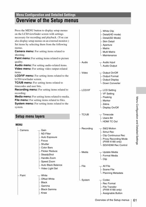
Menu C
onfiguration and Detailed S
ettings
Press the MENU button to display setup menus on the LCD/viewfinder screen with settings necessary for recording and playback. (You can also display setup menus on an external monitor.) Set items by selecting them from the following menus.Camera menu: For setting items related to shooting.Paint menu: For setting items related to picture quality.Audio menu: For setting audio-related items.Video menu: For setting video output-related items.LCD/VF menu: For setting items related to the LCD/viewfinder screen.TC/UB menu: For setting items related to timecodes and user bits.Recording menu: For setting items related to recording.Media menu: For setting items related to media.File menu: For setting items related to files.System menu: For setting items related to the system.
Menu Configuration and Detailed Settings
Overview of the Setup menus
Setup menu layers
MENU
Camera GainND FilterAuto Exposure
FocusShutterColor Bars
Flicker ReduceSteadyShotHandle Zoom
Speed ZoomAuto Black BalanceVideo Light Set
Paint WhiteOffset White
BlackGammaBlack Gamma
Knee
White ClipDetail(HD mode)Detail(SD Mode)
Skin DetailApertureMatrix
Multi MatrixMaintenance
Audio Audio InputAudio Output
Video Output On/OffOutput FormatOutput Display
Down Converter
LCD/VF LCD Setting
VF SettingPeakingMarker
ZebraDisplay On/Off
TC/UB TimecodeUsers BitHDMI TC Out
Recording S&Q MotionSimul Rec
Clip Continuous RecProxy Recording Mode (PXW-X180 only)SDI/HDMI Rec Control
Media Update MediaFormat MediaClip
File All FileScene File
Planning Metadata
System Codec
Rec FormatFile Transfer (PXW-X180 only)Assignable Button
Overview of the Setup menus 61

62
Menu C
onfiguration and Detailed S
ettings
* May not be available depending on the country or area.
The Setup menu, allowing you to perform various settings that are needed for recording and playing, appears on the LCD/viewfinder screen by pressing the MENU button. (You can display the Setup menu on the external video monitor.)
Menu controls
MENU button (page 11)To turn the menu mode to use the setup menus on/off.
SEL/SET dial (page 10)When you turn the dial, the cursor moves up or down, permitting you to select menu items or setting values.Press the SEL/SET dial to select the highlighted item.
CANCEL/BACK button (page 10)To return to the previous menu. An uncompleted change is canceled.
V/v/B/b SET buttonWhen you press the V/v/B/b buttons, the cursor moves in the corresponding direction, permitting you to select menu items or setting values.Press the SET button to enter the highlighted item.
Note
In Focus Magnifier mode (page 30), the setup menu cannot be used.
Setting the Setup menusTurn the SEL/SET dial to set the cursor to the item of the menu you wish to set, then press the SEL/SET dial to select that item.• The menu item selection area can show up to 9
lines. When all the selectable items cannot be displayed at one time, you can scroll the display up or down by moving the cursor.
• For items having a wide range of available values (example: –99 to +99), the available value area is not displayed. The current setting is highlighted instead, indicating that the setting is ready for change.
• When you select “Execute” for an execution item, the corresponding function is executed.
Rec LampLanguage
Clock SetCountryHours Meter
Basic Authentication (PXW-X180 only)
Wi-Fi (PXW-X180 only)GPS* (PXW-X180 only)IR Remote
Battery AlarmAll ResetNetwork Reset (PXW-X180 only)Version
Setup Menu Operations
Setup Menu Operations

Menu C
onfiguration and Detailed S
ettings
• When you select an item that you must confirm before execution, the menu display temporarily disappears, and a confirmation message is displayed. Follow the instructions of the message, and specify whether to execute or cancel.
Entering a character stringWhen you select an item for which a character string, such as a filename, is to be specified, the character input screen appears.
1 Select character type by turning the SEL/SET dial, then press the SEL/SET dial to enter.
ABC: Uppercase alphabeticalabc: Lowercase alphabetical123: Numerical!#$: Special
2 Select a character from the selected character type.
The cursor moves to the next column.Space: Inputs a space on the position of the cursor.B/b: Moves the cursor.BS: Deletes the character on the left of the cursor.
3 Select “Done” after inputting characters.
The input characters are entered and the character input screen disappears.
1
2 3
Setup Menu Operations 63

64
Menu C
onfiguration and Detailed S
ettings
The functions and available settings of menus are listed below.The default settings set at the factory are shown in bold (example: 18dB).
Setup Menu List
Camera menu
Camera
Menu items Sub items and setting values Contents
GainSettings for the gain
Gain<H>–3dB / 0dB / 3dB / 6dB / 9dB / 12dB / 15dB / 18dB
Sets the preset value <H> of the gain.
Gain<M>–3dB / 0dB / 3dB / 6dB / 9dB / 12dB / 15dB / 18dB
Sets the preset value <M> of the gain.
Gain<L>–3dB / 0dB / 3dB / 6dB / 9dB / 12dB / 15dB / 18dB
Sets the preset value <L> of the gain.
Shockless GainOn / Off
Turns the shockless gain function on/off.
ND FilterSettings for the ND filter
Preset11/4 / 1/8 / 1/16 / 1/32 / 1/64 / 1/128
Sets the preset value 1 of the ND filter.
Preset21/4 / 1/8 / 1/16 / 1/32 / 1/64 / 1/128
Sets the preset value 2 of the ND filter.
Preset31/4 / 1/8 / 1/16 / 1/32 / 1/64 / 1/128
Sets the preset value 3 of the ND filter.
Setup Menu List

Menu C
onfiguration and Detailed S
ettings
Auto ExposureSettings for the total level control system
Level–2.0 / –1.75 / –1.5 / –1.25 / –1.0 / –0.75 / –0.5 / –0.25 / 0 / +0.25 / +0.5 / +0.75 / +1.0 / +1.25 / +1.5 / +1.75 / +2.0
Sets the TLCS level.
ModeBacklight / Standard / Spotlight
Set the control mode of TLCS.Backlight: Backlight mode (reduce darkening of the center
subject against lights)Standard: Standard modeSpotlight: Spotlight mode (reduces blown-out highlights on
the center subject in the spotlight)
Speed–99 to +99 (±0)
Sets the control speed of the TLCS.
AGCOn / Off
Turns the AGC (Auto Gain Control) function on/off.
AGC LimitOff / 0dB / 3dB / 6dB / 9dB / 12dB / 15dB
Sets the maximum gain of the AGC function.
Auto ShutterOn / Off
Turns the Auto Shutter control function on/off.
A.SHT LimitOff / 1/100 / 1/150 / 1/200 / 1/250
Sets the fastest shutter speed for the auto shutter function.
Clip High lightOn / Off
Turns the function dulls the response to high luminance on/off by ignoring detection of high luminance.
Detect Window1 / 2 / 3 / 4 / 5 / 6
Selects the photometric range that adjusts exposure automatically according to brightness of subject. (This function is not available when exposure is adjusted manually.)
Detect Window IndicationOn / Off
Turns the detect window on/off.
FocusSettings for the focus
AF AssistOn / Off
By setting this item to on, you can perform manual focus temporarily by turning the focus ring while in the auto focus mode.
Focus MacroOn / Off
Sets whether to include the macro area in the moving range of the focus position.
Camera
Menu items Sub items and setting values Contents
Setup Menu List 65

66
Menu C
onfiguration and Detailed S
ettings
ShutterSettings for the operating conditions of the electronic shutter
ModeSpeed / Angle / ECS / SLS
Select modes of the electronic shutter.Speed/Angle (standard modes): These modes may be
especially effective when you wish to record a quick-moving subject with minimal blurring. You can select Speed mode to specify the shutter speed in seconds, or Angle mode to specify the shutter speed by the shutter angle.
ECS (Extended Clear Scan) mode: This mode may be used to shoot the LCD/viewfinder screen, eliminating horizontal bands.
SLS (Slow shutter mode): This mode sets the shutter speed according to the number of accumulated frames.
Shutter Speed1/32, 1/33, 1/40, 1/48, 1/50, 1/60, 1/96, 1/100, 1/120, 1/125, 1/250, 1/500, 1/1000, 1/2000
Set the shutter speed when Speed mode is selected. The available setting values vary depending on the frame frequency of the video format selected.
Shutter Angle11.25º / 22.5º / 45º / 90º / 180º
Set the shutter angle when Angle mode is selected.
ECS Frequency25.02 to 8000(NTSC Area: 60.00, PAL Area: 50.00)
Set the ECS frequency when ECS mode is selected. The available setting values vary depending on the frame frequency of the video format selected.
SLS Frame2 / 3 / 4 / 5 / 6 / 7 / 8 / 16
Selects the number of accumulated frames in SLS mode.
Color BarsSettings for the color bars
SettingOff / On
Turns the color bars on/off.
TypeARIB / SMPTE / 75% / 100%
Selects the type of color bar.
Flicker ReduceSettings for the flicker correction
ModeAuto / On / Off
Sets the flicker correction mode.
Frequency50Hz / 60Hz(NTSC Area: 60Hz, PAL Area: 50Hz)
Sets the power frequency of lights that cause flicker.
SteadyShotSettings for the SteadyShot function
SettingSteadyShot / Active SteadyShot / Off
Turns the SteadyShot function on/off.
SteadyShot TypeHard / Standard / Soft
Selects the SteadyShot type.
Handle ZoomSetting for the handle zoom speed
Setting1 to 8 (3)
Sets the handle zoom speed.(This setting is available only when the handle zoom switch is set to FIX.)
Speed ZoomSetting for the fast zoom function
SettingOn / Off
Turns the fast zoom function on/off.
Camera
Menu items Sub items and setting values Contents
Setup Menu List

Menu C
onfiguration and Detailed S
ettings
Auto Black BalanceSetting for the automatic black balance
Auto Black BalanceExecute / Cancel
Executes the automatic black balance function.
Notes
• This cannot be set while recording or while the color bars are displayed.
• This cannot be set while using Interval Recording mode, Frame Recording mode, Slow and Quick Motion mode, or Slow Shutter mode.
Video Light Set
Video Light SetPower Link / Rec Link / “Rec Link + Stby”
Sets the lighting method of the video light that is attached to the Multi Interface Shoe.Power Link: The video light is turned on/off by interlocking with the power on/off operation of the camcorder.Rec Link: The video light is turned on/off by interlocking with the recording start/stop operation of the camcorder.“Rec Link + Stby”: The video light is turned on/off (standby status) by interlocking with the recording start/stop operation of the camcorder.
Paint menu
Camera
Menu items Sub items and setting values Contents
Paint
Menu items Sub items and setting values Contents
WhiteSettings for white balance
Preset White2100K to 10000K (3200K)
Performs the preset color temperature adjustment when preset is selected in the white balance mode.
Notes
• You cannot check the change on the screen even if the “Preset White” setting is changed when a setting other than preset is selected in the white balance mode.
Shockless WhiteOff / 1 / 2 / 3
Sets the speed of change in white balance when the white balance mode is switched.Off: Changes instantly.1 to 3: Select a larger number to change the white balance more slowly through interpolation.
White Switch<B>Memory / ATW
Select the white balance adjustment mode selected at the B position of the WHT BAL switch.
ATW Speed1 / 2 / 3 / 4 / 5
Sets the reaction speed when in ATW mode.1: Fastest reaction speed
Offset WhiteSettings for the offset white balance
SettingOn / Off
Turns “Offset White” for the auto white balance (one push) and ATW function on/off.
Offset<A>–99 to +99 (±0)
Adjusts the volume of the offset white for the white memory (A).
Offset<B>–99 to +99 (±0)
Adjusts the volume of the offset white for the white memory (B).
Offset<ATW>–99 to +99 (±0)
Adjusts the volume of the offset white for the ATW.
Setup Menu List 67

68
Menu C
onfiguration and Detailed S
ettings
BlackSettings for the black
SettingOn / Off
Turns the black correction on/off.
Master Black–99 to +99 (±0)
Sets the master black level.
R Black–99 to +99 (±0)
Sets the R black level.
B Black–99 to +99 (±0)
Sets the B black level.
GammaSettings for the gamma compensation
SettingOn / Off
Turns the gamma compensation function on/off.
Step Gamma0.35 to 0.90 (0.45)
Sets the gamma compensation value in 0.05 steps.
Master Gamma–99 to +99 (0)
Sets the master gamma level.
Gamma CategorySTD / HG
Select from among “STD” (standard gamma), “HG.”
Gamma Select
When “Gamma Category” is set to “STD”
STD1 DVW / STD2 ×4.5 / STD3 ×3.5 / STD4 240M / STD5 R709 / STD6 ×5.0
When “Gamma Category” is set to “HG”
HG1 3250G36 / HG2 4600G30 / HG3 3259G40 / HG4 4609G33
Selects the gamma table that is used for the gamma compensation.
Black GammaSettings for the black gamma level
SettingOn / Off
Turns the black gamma compensation function on/off.
Notes
• The black gamma compensation function and the Knee Saturation function of Knee cannot be used at same time.
RangeLow / Mid / High
Selects the effective range for the black gamma compensation.
Master Black Gamma–99 to +99 (±0)
Sets the master black gamma level.
Paint
Menu items Sub items and setting values Contents
Setup Menu List

Menu C
onfiguration and Detailed S
ettings
KneeSettings for the knee compensation
SettingOn / Off
Turns the knee compensation function on/off.(This setting is available only when “Gamma Category” in “Gamma” is set to “STD.”)
Auto KneeOn / Off
Turns the auto knee function on/off.
Point75% to 109% (90%)
Sets the knee point.
Slope–99 to +99 (±0)
Sets the knee slope.
Knee SaturationOn / Off
Set to “On” to enable the knee saturation adjustment (level for the area over the knee point).
Notes
• The black gamma compensation function and the Knee Saturation function of Knee cannot be used at same time.
Knee Saturation Level–99 to +99 (±0)
Adjust the knee saturation level for the area over the knee point.
White ClipSettings for the white clipping adjustment
SettingOn / Off
Turns white clipping adjustment on/off.
LevelWhen setting other than “PAL Area” is selected for “Country”
90.0% to 109.0% (108.0%)When “PAL Area” is selected for “Country”
90.0% to 109.0% (105.0%)
Specifies the white clip level.
Paint
Menu items Sub items and setting values Contents
Setup Menu List 69

70
Menu C
onfiguration and Detailed S
ettings
Detail(HD mode)Settings for the detail adjusting
Manual SettingOn / Off
Turns the detail adjusting function on/off.
Master Level–99 to +99 (±0)
Adjusts the detail level.
H/V Ratio–99 to +99 (±0)
Adjusts the ratio between the H detail level and V detail level.
Crispening–99 to +99 (±0)
Adjusts the crispening level.
Level DependOn / Off
Turns the level depend adjusting function on/off.
Level Depend Level–99 to +99 (±0)
Adjusts the level depend level.
Frequency–99 to +99 (±0)
Specifies the central frequency for details (thickness of details). Larger values give thinner details, smaller values give thicker details.
Knee ApertureOn / Off
Turns the knee aperture function on or off.
Knee Aperture Level–99 to +99 (±0)
Specifies the knee aperture level.
Master Limit–99 to +99 (±0)
Specifies the detail limiter values for both the white-side and black-side directions.
White Limit–99 to +99 (±0)
Adjusts the white detail limiter.
Black Limit–99 to +99 (±0)
Adjusts the black detail limiter.
V Black Limit–99 to +99 (±0)
Adjusts the V black detail limiter.
V Detail CreationNAM / Y / G / G+R
Selects the source signal used to generate the V detail signal from among NAM (G or R, whichever is the signal with the highest level), Y, G, and G+R.
Paint
Menu items Sub items and setting values Contents
Setup Menu List

Menu C
onfiguration and Detailed S
ettings
Detail(SD Mode)Settings for the detail adjusting
Manual SettingOn / Off
Turns the detail adjusting function on/off.
Master Level–99 to +99 (±0)
Adjusts the detail level.
H/V Ratio–99 to +99 (±0)
Adjusts the ratio between the H detail level and V detail level.
Crispening–99 to +99 (±0)
Adjusts the crispening level.
Level DependOn / Off
Turns the level depend adjusting function on/off.
Level Depend Level–99 to +99 (±0)
Adjusts the level depend level.
Frequency–99 to +99 (±0)
Specifies the central frequency for details (thickness of details). Larger values give thinner details, smaller values give thicker details.
Knee ApertureOn / Off
Turns the knee aperture function on or off.
Knee Aperture Level–99 to +99 (±0)
Specifies the knee aperture level.
Master Limit–99 to +99 (±0)
Specifies the detail limiter values for both the white-side and black-side directions.
White Limit–99 to +99 (±0)
Adjusts the white detail limiter.
Black Limit–99 to +99 (±0)
Adjusts the black detail limiter.
V Black Limit–99 to +99 (±0)
Adjusts the V black detail limiter.
V Detail CreationNAM / Y / G / G+R
Selects the source signal used to generate the V detail signal from among NAM (G or R, whichever is the signal with the highest level), Y, G, and G+R.
Skin DetailSettings for the skin detail compensation
SettingOn / Off
Turns the skin detail compensation function on/off.
Area DetectionExecute / Cancel
Detects the color for the skin detail compensation.Execute: Executes this function.
Area IndicationOn / Off
Turns the function that displays the zebra pattern in the target area for the skin detail compensation on/off.
Level–99 to +99 (±0)
Adjusts the skin detail level.
Saturation–99 to +99 (±0)
Adjusts the color saturation level for the skin detail compensation.
Hue0 to 359
Adjusts the color hue for the skin detail compensation.
Width0 to 90 (40)
Adjusts the width of the color hue for the skin detail compensation.
Paint
Menu items Sub items and setting values Contents
Setup Menu List 71
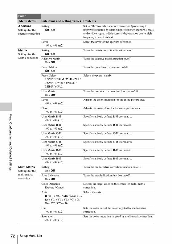
72
Menu C
onfiguration and Detailed S
ettings
ApertureSettings for the aperture correction
SettingOn / Off
Set to “On” to enable aperture correction (processing to improve resolution by adding high-frequency aperture signals to the video signal, which corrects degeneration due to high-frequency characteristics).
Level–99 to +99 (±0)
Select the level for the aperture correction.
MatrixSettings for the Matrix correction
SettingOn / Off
Turns the matrix correction function on/off.
Adaptive MatrixOn / Off
Turns the adaptive matrix function on/off.
Preset MatrixOn / Off
Turns the preset matrix function on/off.
Preset Select1:SMPTE 240M / 2:ITU-709 / 3:SMPTE Wide / 4:NTSC / 5:EBU / 6:PAL
Selects the preset matrix.
User MatrixOn / Off
Turns the user matrix correction function on/off.
Level–99 to +99 (±0)
Adjusts the color saturation for the entire picture area.
Phase–99 to +99 (±0)
Adjusts the color phase for the entire picture area.
User Matrix R-G–99 to +99 (±0)
Specifies a freely defined R-G user matrix.
User Matrix R-B–99 to +99 (±0)
Specifies a freely defined R-B user matrix.
User Matrix G-R–99 to +99 (±0)
Specifies a freely defined G-R user matrix.
User Matrix G-B–99 to +99 (±0)
Specifies a freely defined G-B user matrix.
User Matrix B-R–99 to +99 (±0)
Specifies a freely defined B-R user matrix.
User Matrix B-G–99 to +99 (±0)
Specifies a freely defined B-G user matrix.
Multi MatrixSettings for the multi-matrix correction
SettingOn / Off
Turns the multi-matrix correction function on/off .
Area IndicationOn / Off
Turns the area indication function on/off .
Color DetectionExecute / Cancel
Detects the target color on the screen for multi-matrix correction.
AxisB / B+ / MG- / MG / MG+ / R /R+ / YL- / YL / YL+ / G- / G / G+ / CY / CY+ / B-
Selects the axis.
Hue–99 to +99 (±0)
Sets the color hue of the color targeted by multi-matrix correction.
Saturation–99 to +99 (±0)
Sets the color saturation targeted by multi-matrix correction.
Paint
Menu items Sub items and setting values Contents
Setup Menu List

Menu C
onfiguration and Detailed S
ettings
MaintenanceSetting for maintenance
Test SawOn / Off
Turns the test signal on/off.
Paint
Menu items Sub items and setting values Contents
Audio menu
Audio
Menu items Sub items and setting values Contents
Audio InputSettings for audio inputs
INPUT1 Reference–60dB / –50dB / –40dB
Selects the reference input level for when the INPUT1 switch is set to MIC.
INPUT2 Reference–60dB / –50dB / –40dB
Selects the reference input level for when the INPUT2 switch is set to MIC.
INT MIC SensitivityNormal / High
Selects the sensitivity of the internal microphone.
INPUT1 Wind FilterOn / Off
Turns the wind filter for CH1 on/off.
INPUT2 Wind FilterOn / Off
Turns the wind filter for CH2 on/off.
INT MIC Wind FilterOn / Off
Turns the wind filter for the internal stereo microphone on/off.
SHOE MIC Wind FilterOn / Off
Turns the wind filter for the shoe microphone on/off.
Limiter ModeOn / Off
Turns the limiter on/off when a loud signal is input while setting audio input level manually.
AGC ModeMono / Stereo
Selects the cross-channel linkage of the AGC.
INPUT CH SelectINPUT1/INPUT1 / INPUT1/INPUT2
INPUT1/INPUT1: Records the INPUT1 signal to both CH-1 and CH-2.INPUT1/INPUT2: Records the INPUT1 signal to CH-1, and the INPUT2 signal to CH-2.
1kHz Tone on Color BarsOn / Off
Turns the 1-kHz reference tone signal on/off.
Audio OutputSettings for audio outputs
Headphone OutMono / Stereo
Selects the headphones output, “Mono” or “Stereo.”
Alarm Volume0 to 7 (4)
Sets the alarm volume.
Setup Menu List 73

74
Menu C
onfiguration and Detailed S
ettings
Video menu
Video
Menu items Sub items and setting values Contents
Output On/OffSettings for the video output
SDIOn / Off
Turns the SDI output on/off.
HDMIOn / Off
Turns the HDMI output on/off.
Output FormatSettings for the output format• For details about
the setting items, see “Video Formats and Output Signals” (page 97)
SDI/HDMI Sets the resolution of the SDI/HDMI output.SET: Execute this function.
VIDEO Displays the resolution and scan method. (Display only)
Output DisplaySettings for the output signal
SDI/HDMIOn / Off
Selects whether to add the menu or status on the SDI/HDMI output signal.
VIDEOOn / Off
Selects whether to add the menu or status on the video output signal.
Down ConverterSelection for the operation mode of the down converter
Squeeze / Letter Box / Edge Crop Set the output mode (aspect) for SD signalsSqueeze: To horizontally reduce a 16:9 picture to output a 4:3
pictureLetter Box: To mask the upper and lower areas of a 4:3
picture to display a 16:9 picture in the center of the screenEdge Crop: To cut both sides of a 16:9 picture to output a 4:3
picture
Setup Menu List

Menu C
onfiguration and Detailed S
ettings
LCD/VF menu
LCD/VF
Menu items Sub items and setting values Contents
LCD SettingSettings for the LCD screen
Color–99 to +99 (±0)
Adjusts the color saturation of the LCD screen.
Brightness–99 to +99 (±0)
Adjusts the brightness of the LCD screen.
VF SettingSettings for the viewfinder
Brightness–99 to +99 (±30)
Adjusts the brightness of the viewfinder.
Color ModeColor / B&W
Selects the display mode of the viewfinder during E-E display/recording.
PeakingSettings for the peaking function
SettingOn / Off
Turns the peaking function on/off.
Peaking TypeNormal / Color
Selects the peaking type.Normal: Normal peakingColor: Color peaking
FrequencyNormal / High
Selects “Normal” or “High” as the peaking frequency.
Normal Peaking Level0 to 99 (50)
Sets the normal peaking level.
ColorB&W / Red / Yellow / Blue
Selects the signal color of the color peaking.
Color Peaking Level0 to 99 (50)
Sets the color peaking level.
MarkerSettings for the marker indications
SettingOn / Off
Turns all marker indications on/off.
Center Marker1 / 2 / 3 / 4 / Off
Turns on/off the center marker.
Safety ZoneOn / Off
Turns the safety zone marker on/off.
Safety Area80% / 90% / 92.5% / 95%
Selects the size (ratio to the entire screen) of the safety zone marker.
Aspect MarkerLine / Mask / Off
Selects the aspect marker.Line: Show as white lines.Mask: Display by lowering the video signal level of areas
outside the marker range.Off: The aspect marker is not displayed.
Aspect Mask0 to 15 (12)
When “Aspect Marker” is set to “Mask,” specifies the brightness of areas outside the aspect marker.
Aspect Select4:3 / 13:9 / 14:9 / 15:9 / 16:9/ 17:9 / 1.66:1 / 1.85:1 / 2.35 :1 / 2.4:1
Select the ratio of the aspect marker.
Guide FrameOn / Off
Turns the guide frame display on/off.
Setup Menu List 75

76
Menu C
onfiguration and Detailed S
ettings
ZebraSettings for the zebra pattern
SettingOn / Off
Turns the zebra function on/off.
Zebra Select1 / 2 / Both
Select the zebra pattern(s) (Zebra 1, Zebra 2, or both of Zebra 1 and Zebra 2) to be displayed.
Zebra1 Level50% to 107% (70%)
Sets the display level of zebra 1.
Zebra1 Aperture Level1% to 20% (10%)
Sets the aperture level of zebra 1.
Zebra2 Level52% to 109% (100%)
Sets the display level of zebra 2.
Display On/OffSettings for the items to be displayed
Shutter SettingOn / Off
Selects the items to be displayed on the LCD/viewfinder screen.
ND Filter PositionOn / Off
Gain SettingOn / Off
Rec/Play StatusOn / Off
Color Temp.On / Off
Frame RateOn / Off
Battery RemainOn / Off
TimecodeOn / Off
Audio ManualOn / Off
Audio Level MeterOn / Off
Media StatusOn / Off
Focus PositionMeter / Feet / Off
Iris PositionOn / Off
Zoom PositionNumber / Bar / Off
Focus MacroOn / Off
SteadyShotOn / Off
Focus ModeOn / Off
Auto ShutterOn / Off
AGCOn / Off
LCD/VF
Menu items Sub items and setting values Contents
Setup Menu List

Menu C
onfiguration and Detailed S
ettings
Auto IrisOn / Off
AE ModeOn / Off
White Balance ModeOn / Off
SDI/HDMI Rec ControlOn / Off
Rec FormatOn / Off
GammaOn / Off
Timecode LockOn / Off
Audio FormatOn / Off
Wi-Fi Condition (PXW-X180 only)
On / Off
Video Signal MonitorOff / Waveform / Vector / Histogram
Clip NameOn / Off
Focus Assist BarOn / Off
Focus Area MarkerOn / Off
Video Level WarningOn / Off
Clip NumberOn / Off
GPS (PXW-X180 only)On / Off
Proxy Status (PXW-X180 only)On / Off
Lens InfoMeter / Feet / Off
LCD/VF
Menu items Sub items and setting values Contents
Setup Menu List 77

78
Menu C
onfiguration and Detailed S
ettings
TC/UB menu
TC/UB
Menu items Sub items and setting values Contents
TimecodeSettings for the timecode
ModePreset / Regen / Clock
Selects the timecode mode.Preset: Starts the timecode from the specified value.Regen (regeneration): Starts the timecode by continuing the timecode of the previous clip.Clock: Uses the internal clock as the timecode.
RunRec Run / Free Run
Rec Run: To advance the timecode during recording only. Free Run: The timecode keeps advancing regardless of the state of recording.
Setting Sets the timecode to a desired value.SET: Sets the value.
ResetExecute / Cancel
Resets the timecode to 00:00:00:00.Execute: Execute this function.
TC FormatDF / NDF
Selects the timecode format.DF: Drop frameNDF: Non drop frame
Users BitSettings for the users bit
ModeFix / Time
Sets the users bit mode.Fix: Uses a desired fixed value as the users bit.Time: Uses the current date.
Setting Sets the users bit to a desired value.
HDMI TC Out SettingOn / Off
Sets whether to output the time code to another device for professional use via HDMI.
Setup Menu List

Menu C
onfiguration and Detailed S
ettings
Recording menu
Recording
Menu items Sub items and setting values Contents
S&Q MotionSettings for the Slow & Quick motion mode
SettingOn / Off
Turns the Slow & Quick motion mode on/off.
Frame Rate1P to 60P / 72P / 75P / 80P / 90P / 96P / 100P / 110P / 120P
Sets the frame rate during shooting with the Slow & Quick motion function when S&Q setting is “On.”
Simul RecSettings for the simultaneously recording function
SettingOn / Off
Turns the simultaneously recording function on/off, and sets the destination media.
Rec Button Set
Rec Button: Handle Rec Button:
/ Rec Button:
Handle Rec Button: /
Rec Button: Handle Rec
Button:
Assigns the record button to perform the recording operation for each media.
Clip Continuous RecSettings for the Clip Continuous Recording function
SettingOn / Off
Turns the Clip Continuous Recording function on/off.
Proxy Recording Mode(PXW-X180 only) Settings for the proxy recording mode
SettingOn / Off
Turns the proxy recording mode on/off.
Size1280×720(9Mbps) / 640×360(3Mbps) / 480×270(1Mbps) / 480×270(0.5Mbps)
Sets the picture size for the proxy file.
Frame Rate Displays the frame rate.
Bit Rate Displays the bit rate.
SDI/HDMI Rec ControlSettings for the SDI/HDMI recording control function
SettingOn / Off
Turns the recording/stop recording controls of the external device via the SDI/HDMI output signal on/off.
Setup Menu List 79

80
Menu C
onfiguration and Detailed S
ettings
This menu is not available when media is not loaded.
Media menu
Media
Menu items Sub items and setting values Contents
Update MediaUpdating media
Media(A)Execute / Cancel
Updates the managerial file on the SxS memory card in slot A.
Media(B)Execute / Cancel
Updates the managerial file on the SxS memory card in slot B.
Format MediaFormatting media
Media(A)Execute / Cancel
Formats the SxS memory card in slot A.Execute: Executes format.
Media(B)Execute / Cancel
Formats the SxS memory card in slot B.Execute: Executes format.
SD cardExecute / Cancel
Formats the UTILITY SD card.Execute: Executes format.
Proxy (PXW-X180 only)Execute / Cancel
Formats the PROXY SD card.Execute: Executes format.
Setup Menu List

Menu C
onfiguration and Detailed S
ettings
ClipSettings for clip naming or deletion
Auto NamingTitle / Plan
Selects the method to specify clip names.Title: Specifies by using the name specified in “Title Prefix.”Plan: Uses a name specified in planning metadata. If no name
is specified in planning metadata, the name specified by “Title Prefix” is used.
Title Prefixnnn_ (nnn=least three digits of the serial number)(Max. 7 characters displayed)
Calls the Character Set screen to set the title part (4 to 46 characters) of the clip names.Configuration of the Character Set screenCharacter selection area (3 lines):
Selects the characters to insert in the cursor position of the Title Prefix area.!#$%()+,-.=@[]^_~0123456789abcdefghijklmnopqrstuvwxyzABCDEFGHIJKLMNOPQRSTUVWXYZ
Cursor operation area (1 line):Space: Changes the character in the cursor position to a
spaceINS: Inserts a space in the cursor positionDEL: Deletes a character in the cursor positionT: Moves the cursor to the leftt: Moves the cursor to the rightESC: Cancels the changes and exits the Character Set
screenEND: Validates the changes and exits the Character Set
screenTitle Prefix area (1 line):
For entering the titleTo set the title1 Using the V/v/B/b buttons, select (highlight) a character in
the character selection area to be entered in the cursor position of the Title Prefix area. Then press the SEL/SET dial.
2 Repeat Step 1 for setting the title. (Use Space, INS, and DEL as required.)
3 When the title setting is completed, select END to exit the Character Set screen.
Number Set0001 to 9999
Sets the second 4-numeric part of the clip name.Sets a five-digit number for a planning metadata file.
Media
Menu items Sub items and setting values Contents
Setup Menu List 81

82
Menu C
onfiguration and Detailed S
ettings
File menu
File
Menu items Sub items and setting values Contents
All FileSettings for the All file
Load SD CardExecute / Cancel
Loads the All file.Execute: Executes this function.
Save SD cardExecute / Cancel
Stores the All file.Execute: Executes this function.
File ID Names the file.
Scene FileSettings for the Scene file
Recall Internal MemoryExecute / Cancel
Loads the Scene file from the internal memory.Execute: Executes this function.
Store Internal MemoryExecute / Cancel
Stores the Scene file to the internal memory.Execute: Executes this function.
Load SD CardExecute / Cancel
Recalls from an SD card by selecting “Execute.”
Save SD cardExecute / Cancel
Stores to an SD card by selecting “Execute.” The setup file is stored to the following directories.For PXW-X180: /Private/Sony/PRO/CAMERA/PXW-X180/For PXW-X160: /Private/Sony/PRO/CAMERA/PXW-X160/
File ID Names the file.
Scene White DataOn / Off
Sets whether to apply the White Balance data when recalling the Scene File.
Planning MetadataSettings for operation of planning metadata
Load Media(A) or Load Media(B)Execute / Cancel
To load planning metadata from the SxS memory card in slot A or B.Selecting “Execute” displays the list of the planning metadata files stored on the SxS memory card in slot A or B. Specify a file, select “Load” then “Execute” for loading.
Notes
• The file list displays up to 64 files. Even if the total number of planning metadata files is 64 or less, all of the planning metadata files may not appear if the directory where they are located in the SxS memory card (XDROOT/General/Sony/Planning) contains 512 or more files.
• After you start loading, do not remove the SxS memory card until the completion message is displayed.
PropertiesExecute / Cancel
Select “Execute” to display the detailed information of the planning metadata loaded in the camcorder.File Name: File nameAssign ID: Assignment IDCreated: Time and date of creationModified: Time and date of most recent modificationModified by: Name of person who modified the fileTitle1: Title1 specified in file (clip name in ASCII-format)Title2: Title2 specified in file (clip name in UTF-8-format)Material Group: Number of material groups (groups of clips
recorded using the same planning metadata)Shot Mark0 to 9: Name defined for Shot Mark 0 to 9
Clear MemoryExecute / Cancel
Select “Execute” to clear the planning metadata loaded in the camcorder.
Clip Name DispTitle1(ASCII) / Title2(UTF-8)
Selects the display mode of the clip name specified in planning metadata.
Setup Menu List

Menu C
onfiguration and Detailed S
ettings
System menu
System
Menu items Sub items and setting values Contents
Codec SelectXAVC-I / XAVC-L / MPEG HD422 / MPEG HD420 / DVCAM / AVCHD
Sets the recording/playback mode.
Rec FormatSettings for the recording format
Video Format Sets the recording format.SET: Executes.
• NTSC Area:When “Select” in “Codec” is set to “XAVC-I”
1920×1080 59.94i1920×1080 29.97P1920×1080 23.98P1280×720 59.94P
When “Select” in “Codec” is set to “XAVC-L”
1920×1080 59.94P 501920×1080 59.94P 351920×1080 59.94i 501920×1080 59.94i 351920×1080 59.94i 251920×1080 29.97P 501920×1080 29.97P 351920×1080 23.98P 501920×1080 23.98P 351280×720 59.94P 50
When “Select” in “Codec” is set to “MPEG HD422”
1920×1080 59.94i 501920×1080 29.97P 501920×1080 23.98P 501280×720 59.94P 501280×720 29.97P 501280×720 23.98P 50
When “Select” in “Codec” is set to “MPEG HD420”
1920×1080 59.94i HQ1920×1080 29.97P HQ1920×1080 23.98P HQ1440×1080 59.94i HQ1280×720 59.94P HQ
When “Select” in “Codec” is set to “DVCAM”
720×480 59.94iWhen “Select” in “Codec” is set to “AVCHD”
1920×1080 59.94P1920×1080 59.94i1920×1080 29.97P1920×1080 23.98P1280×720 59.94P
• PAL AreaWhen “Select” in “Codec” is set to “XAVC-I”
1920×1080 50i1920×1080 25P1280×720 50P
When “Select” in “Codec” is set to “XAVC-L”
1920×1080 50P 501920×1080 50P 351920×1080 50i 501920×1080 50i 351920×1080 50i 251920×1080 25P 501920×1080 25P 351280×720 50P 50
When “Select” in “Codec” is set to “MPEG HD422”
1920×1080 50i 501920×1080 25P 501280×720 50P 501280×720 25P 50
When “Select” in “Codec” is set to “MPEG HD420”
1920×1080 50i HQ1920×1080 25P HQ1440×1080 50i HQ1280×720 50P HQ
When “Select” in “Codec” is set to “DVCAM”
720×576 50iWhen “Select” in “Codec” is set to “AVCHD”
1920×1080 50P1920×1080 50i1920×1080 25P1280×720 50P
Setup Menu List 83
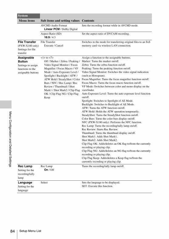
84
Menu C
onfiguration and Detailed S
ettings
AVCHD Audio FormatLinear PCM / Dolby Digital
Sets the recording format while in AVCHD mode.
Aspect Ratio (SD)16:9 / 4:3
Set the aspect ratio of DVCAM recording.
File Transfer(PXW-X180 only) Settings for file transfer
File TransferExecute / Cancel
Switches to the mode for transferring original files to an SxS memory card via wireless LAN connection.
Assignable ButtonSettings to assign functions to the assignable buttons
<1> to <7>Off / Marker / Zebra / Peaking / Video Signal Monitor / Focus Magnifier / Focus Macro / VF Mode / Auto Exposure Level / Spotlight / Backlight / ATW / ATW Hold / SteadyShot / Color Bars / NFC / Rec Lamp / Rec Review / Thumbnail / Shot Mark1 / Shot Mark2 / Clip Flag OK / Clip Flag NG / Clip Flag Keep
Assign a function to the assignable buttons.Marker: Turns the marker on/off.Zebra: Turns the zebra function on/off.Peaking: Turns the peaking function on/off.Video Signal Monitor: Switches the video signal indication (such as Histogram).Focus Magnifier: Turns the focus magnifier function on/off.Focus Macro: Turns the focus macro function on/off.VF Mode: Switches between color and mono display on the viewfinder.Auto Exposure Level: Turns the auto exposure level function on/off.Spotlight: Switches to Spotlight of AE Mode.Backlight: Switches to Backlight of AE Mode.ATW: Turns the ATW function on/off.ATW Hold: Holds the ATW operation temporarily.SteadyShot: Turns the SteadyShot function on/off.Color Bars: Turns the color bars display on/off.NFC (PXW-X180 only): Performs the NFC function.Rec Lamp: Turns the recording/tally lamp on/off.Rec Review: Starts Rec Review.Thumbnail: Turns the thumbnail display on/off.Shot Mark1: Adds Shot Mark1.Shot Mark2: Adds Shot Mark2.Clip Flag OK: Adds/deletes an OK flag to/from the currently recording or playing clip.Clip Flag NG: Adds/deletes an NG flag to/from the currently recording or playing clip.Clip Flag Keep: Adds/deletes a Keep flag to/from the currently recording or playing clip.
Rec LampSetting for the recording/tally lamp
Rec LampOn / Off
Turns the recording/tally lamp on/off.
LanguageSetting for the language
Select Sets the language to be displayed.SET: Execute this function.
System
Menu items Sub items and setting values Contents
Setup Menu List

Menu C
onfiguration and Detailed S
ettings
Clock SetSettings for the built-in clock
Time ZoneUTC –12:00 Kwajalein to UTC +14:00
Sets the time-zone difference from UTC in steps of 30 minutes.
Date ModeYYMMDD / MMDDYY / DDMMYY
Selects the display mode of the date.YYMMDD: In year, month, dayMMDDYY: In month, day, yearDDMMYY: In day, month, year
12H/24H12H / 24H
Selects the display mode of time.12H: 12-hour mode24H: 24-hour mode
Date Sets the current date.SET: Sets the date.
Time Sets the current time.SET: Sets the time.
CountrySetting for the region
NTSC/PAL Area Sets the region in which you use the camcorder.Execute: Execute this function.
Hours MeterDisplay for the hours meter
Hours(System) Displays the non-resettable accumulated time of use.
Hours(Reset) Displays the resettable accumulated time of use.
ResetExecute / Cancel
Resets the “Hours(Reset)” value to 0.Execute: Execute resetting.
Basic Authentication(PXW-X180 only) Settings for basic authentication of the network
User Name(admin)
Sets a desired user name (1 to 16 alphanumeric characters).SET: Sets the user name.
Password(pxw-x180)
Sets the password (1 to 16 alphanumeric characters).SET: Execute this function.
Wi-Fi(PXW-X180 only) Settings for wireless LAN connection and respective display items
NFCExecute / Cancel
Selects whether to enable the NFC function or not. When “Execute” is selected, the NFC function turns on and “Setting” is set to “Access Point” temporarily, and the camcorder goes into standby mode for NFC. When “Cancel” is selected, settings return to the previous settings.
SettingAccess Point / Station / Off
Sets the operation mode of the wireless LAN connection.
ChannelAuto / CH1 / CH2 / CH3 / CH4 / CH5 / CH6 / CH7 / CH8 / CH9 / CH10 / CH11 / CH12 / CH13
Sets the wireless LAN channel.
SSID & Password Displays the SSID and password.
WPSExecute / Cancel
Starts Wi-Fi Protected Setup (WPS).
IP Address Displays the IP address of the camcorder.
Subnet Mask Displays the subnet mask of the camcorder.
MAC Address Displays the MAC address of the wireless LAN module of the camcorder.
Regenerate Password Execute / Cancel
Regenerates the password.Execute: Executes this function.
System
Menu items Sub items and setting values Contents
Setup Menu List 85

86
Menu C
onfiguration and Detailed S
ettings
GPS(PXW-X180 only) Setting for GPS
GPSOn / Off
Turns the GPS function on/off.
IR RemoteActivating/deactivating the Remote Commander
SettingOn / Off
Set to “On” to activate remote control operations from the supplied Wireless Remote Commander.
Battery AlarmSettings for the low power alarm
Low BATT5% / 10% / 15% / ... / 45% / 50%
Sets the battery level at which the low voltage warning is generated (in steps of 5%).
BATT Empty3% to 7% (3%)
Sets the battery level at which the battery empty warning is generated.
DC Low Volt116.0 V to 19.0 V (16.0 V)
Set the DC IN voltage at which the low voltage warning is generated.
DC Low Volt215.5 V to 18.5 V (15.5 V)
Set the DC IN voltage at which the warning for the shortage of the voltage is generated.
All ResetResetting to the factory status
ResetExecute / Cancel
Resets the camcorder to the factory status.Execute: Executes resetting.
Network Reset(PXW-X180 only)Resetting of the network settings
ResetExecute / Cancel
Resets the network settings.
VersionDisplay of the version of this camcorder
NumberVx.xx
Displays the current software version of the camcorder.
Version UpExecute / Cancel
Upgrades the camcorder*.Execute: Executes.
* Upgrade is the function for updating the software of the camcorder.
Net-Func Version Number (PXW-X180 only)
Vx.xx
Displays the version for the wireless LAN connecting function of the camcorder.
Net-Func Ver.Up (PXW-X180 only)
Execute / Cancel
Upgrades the version for the wireless LAN connecting function of the camcorder.
System
Menu items Sub items and setting values Contents
Setup Menu List

External D
evices Connection
To display recording or playback pictures on an external monitor, select the output signal and use an appropriate cable for the monitor to be connected.An output signal from the camcorder can be recorded when a recording device is connected. The same status information and menus can be displayed on the external monitor as those on the viewfinder screen.According to the signal fed to the monitor, set “Output Display” (page 74) in the Video menu to “On.”
SDI OUT connector (BNC type)Set the on/off setting of the output, and the output format in the Video menu (page 74).Use a commercially available 75-ohm coaxial cable for connection.
Notes
• Be sure to ground between the camcorder and external device before turning the power on. (We recommend to turn on the camcorder and external device after connecting a 75-ohm coaxial cable.)When connecting an external device to the camcorder while the camcorder is turned on, connect the external device after connecting a 75-ohm coaxial cable to the external device.
To start synchronized recording on an external deviceWith SDI signal output selected, synchronized recording is possible by feeding a REC trigger signal to an external recording device connected via the SDI OUT connector. To enable synchronized recording, set “SDI/HDMI Rec Control” (page 79) of the Recording menu to “On.”
Notes
• When a connected external device does not correspond to a REC trigger signal, the device cannot be operated.
HDMI OUT connector (Type A connector)Set the on/off setting of the output, and the output format in the Video menu (page 74).Use a commercially available high speed HDMI cable for connection.
GENLOCK/VIDEO connector (BNC type)The GENLOCK/VIDEO connector can output the HD-Y signal, HD-Sync Signal, or the down-converted SD analog composite signal for the monitor by changing the setting in “Output Format” of the Video menu.Use the commercially available BNC cable for connection.For details, see “Video Formats and Output Signals” (page 97).
AUDIO OUT connector (3.5 mm stereo pin connector)The AUDIO OUT connector can output 2 channel audio signals.Use the supplied audio connecting cable for connection.
External Devices Connection
Connecting External Monitors and Recording Devices
Connecting External Monitors and Recording Devices 87

88
External D
evices Connection
When multiple units of the camcorder are used in the same shooting location, recording can be synchronized with a specific reference signal, and the timecode can be matched among all the units.
Aligning the phase of the video signal (Genlock)Genlock operation is enabled by supplying a reference signal to the GENLOCK/VIDEO connector (page 9) of the camcorder.Valid reference signals depend on the frame rate of the selected recording format.
For “NTSC Area”
For “PAL Area”
Notes
• Both video signal and timecode signal need to be input when the selected recording format is 1280×720 60P.
• If the reference signal is unstable, genlock is not possible.
• The subcarrier is not synchronized.
Synchronizing the timecode of your camcorder with that of another unitSet the unit that supplies the timecode to a mode in which the timecode output keeps advancing (Free Run or Clock mode).
1 Set “Timecode” in the TC/UB menu as follows:Mode: PresetRun: Free Run
2 Press the DURATION/TC/U-BIT button (page 11) so that the timecode is displayed on the screen.
3 Confirm that the GENLOCK/TC switch (page 9) is set to IN, then supply an HD or SD reference video signal to the GENLOCK/VIDEO connector and the reference timecode to the TC connector.
The built-in timecode generator of your camcorder locks to the reference timecode, and the message “Ext LK” is displayed on the screen.About 10 seconds after locking, even if the reference timecode from the external device is disconnected, the external lock will be kept.
Notes
• Check that the reference timecode and the reference video signal are in a phase relation that complies the SMPTE timecode standards.
• When you finish the above procedure, the timecode is immediately synchronized with the external timecode, and the time data indication will show the value of the external timecode. However, wait for a few seconds until the timecode generator stabilizes before recording.
• If the frequency of the reference video signal and the frame frequency are not the same, a lock cannot be acquired, and the camcorder will not operate properly. In such a case, the timecode will not be correctly locked to the external timecode.
• When the connection is removed, the timecode advance may shift one frame per hour with respect to the reference timecode.
To release the external timecode synchronizationChange the “Timecode” setting in the TC/UB menu or set the camcorder to OFF.External synchronization is also released when you start recording in a special recording mode (Slow & Quick Motion).
External Synchronization
Frame rate of the recording format
Valid reference signal
59.94P 1920×1080 59.94i720×486 59.94i1280×720 59.94P
29.97P 1920×1080 59.94i720×486 59.94i
23.98P 1920×1080 47.95i (23.98PsF)
59.94i 1920×1080 59.94i720×486 59.94i
Frame rate of the recording format
Valid reference signal
50P 1920×1080 50i720×576 50i1280×720 50P
25P 1920×1080 50i720×576 50i
50i 1920×1080 50i720×576 50i
External Synchronization

External D
evices Connection
Synchronizing the timecode of another unit with that of your camcorder
1 Specify the timecode of your camcorder with “Timecode” of the TC/UB menu (page 78).
2 Confirm that the GENLOCK/TC switch (page 9) is set to OUT, then connect the TC connector and GENLOCK/VIDEO connector (page 9) with the timecode input and reference signal input of the other unit, respectively.
To use an SxS card reader (sold separately)When you connect the SBAC-US20 SxS card reader (sold separately) using a USB cable, the memory card in the slot is acknowledged as an extended drive by the computer.
To use mass storage mode of the camcorder
1 Set the power switch to on to turn on the camcorder.
A message prompting you to confirm that you wish to enable the USB connection is displayed on the LCD/viewfinder screen.
• This message will not be displayed while another confirmation message or an in-progress message (e.g., for formatting or restoring an SxS memory card) is shown on the screen. It appears when formatting or restoration has completed. The message is also not displayed while the screen for the detailed information of a clip is shown on the screen. It appears when an operation on the screen for the detailed information of a clip is completed or you return to the thumbnail screen.
2 Select “Execute” by turning the SEL/SET dial.
3 With Windows, check that the memory card is displayed as a removable disk in My Computer.With Macintosh, check that a “NO NAME” or “Untitled” folder was created on the desktop. (The Macintosh folder name can be changed.)
Operating Clips with a Computer
Connecting with a USB Cable
Notes
Operating Clips with a Computer 89

90
External D
evices Connection
Notes
• The following operations must be avoided when the access lamp is lit in red.—Turning the power off or disconnecting the power
cord (main lead)—Removing the SxS memory card—Disconnecting the USB cable
• When removing an SxS memory card from a Macintosh, do not select “Card Power Off” from the SxS memory card icon displayed on the menu bar.
• Operation is not guaranteed with all computers.
Using a nonlinear editing systemFor a nonlinear editing system, an editing software that corresponds to the recording formats used with this camcorder (sold separately) is required.Store the clips to be edited on the HDD of your computer in advance, using the dedicated application software.
Operating Clips with a Computer

Appendices
Recording media and compatible formats
x Normal recording
a: Compatible–: Incompatible
x S&Q mode
a: Compatible–: Incompatible
x Simultaneous recording
a: Compatible–: IncompatibleRecord simultaneously in a memory card of the same type.
*1 Not all memory cards are guaranteed for operation.*2 Simultaneous recording available only in 25 Mbps.If you are using memory cards other than Sony SxS, operation may not be guaranteed.If you are using memory cards other than XQD memory cards (S series, N series, H series), operation may not be guaranteed.
Appendices
Important Notes on Operation
About Recording Media
SxS Pro SxS Pro+ SxS-1 XQD SDXC SDHCMemory Stick
XAVC-I a a a a – – –
XAVC-L a a a a a*1 – –
MPEG HD422 a a a a a*1 – –
MPEG HD420 a a a a a*1 – –
DVCAM a a a a a*1 – –
AVCHD – – – – a*1 a*1 a*1
SxS Pro SxS Pro+ SxS-1 XQD SDXC SDHCMemory Stick
XAVC-I a a – a – – –
XAVC-L a a a a – – –
MPEG HD422 a a a a – – –
SxS Pro SxS Pro+ SxS-1 XQD SDXC SDHCMemory Stick
XAVC-I a a a a – – –
XAVC-L a a a a a*1*2 – –
MPEG HD422 a a a a – – –
MPEG HD420 a a a a – – –
DVCAM – – – – – – –
AVCHD – – – – a*1 a*1 a*1
Important Notes on Operation 91

92
Appendices
a: Compatible–: Incompatible
(Unit: Hour)
Special Recording and Compatible Formats
XAVC-I XAVC-LMPEG HD422
MPEG HD420
AVCHD DVCAM
Normal recording a a a a a a
S&Q Motion a a a – – –
Clip Continuous Rec a a a – – –
Maximum Recording Time for a Clip
Recording formatMaximum recording time (approx.)
XAVC-I 6
XAVC-L 6
MPEG HD422 6
MPEG HD420 6
AVCHD 13
DVCAM 6
Important Notes on Operation

Appendices
Power supplyYou can use your camcorder in any country/region using the AC Adaptor ACDP-060S01 (supplied) or optional Charger BC-U1/U2 within the AC 100 V to 240 V, 50 Hz/60 Hz range.
Viewing on TVBefore recording a movie with your camcorder for viewing on a TV, set “NTSC/PAL Area” in “Country” of System menu to the appropriate TV system for the country/region in which you intended to view the movie. The following shows which countries and regions require “NTSC Area” or “PAL Area” setting.NTSC Area:Bahama Islands, Bolivia, Canada, Central America, Chile, Colombia, Ecuador, Guyana, Jamaica, Japan, Korea, Mexico, Peru, Surinam, Taiwan, the Philippines, the U.S.A., Venezuela, etc. PAL Area:Argentina, Australia, Austria, Belgium, Brazil, Bulgaria, China, Czech Republic, Denmark, Finland, France, Germany, Guiana, Holland, Hong Kong, Hungary, Iran, Iraq, Italy, Kuwait, Malaysia, Monaco, New Zealand, Norway, Paraguay, Poland, Portugal, Russia, Singapore, Slovak Republic, Spain, Sweden, Switzerland, Thailand, Ukraine, United Kingdom, Uruguay, etc.
Simple setting of the clock by time differenceWhen you are abroad, set “Time Zone” of “Clock Set” in the System menu (page 85).
Use and Storage
Do not subject the unit to severe shockThe internal mechanism may be damaged or the body warped.
Do not cover the unit while operatingPutting a cloth, for example, over the unit can cause excessive internal heat build-up.
After useAlways set the power switch to off.
Before storing the unit for a long periodRemove the battery pack.
Do not leave the camcorder with the lenses facing the sunDirect sunlight can enter through the lenses, be focused in the camcorder, and cause fire.
Shipping• Remove the memory cards before transporting
the unit.• If sending the unit by truck, ship, air or other
transportation service, pack it in the shipping carton of the unit.
Care of the unitIf the body of the unit is dirty, clean it with a soft, dry cloth. In extreme cases, use a cloth steeped in a little neutral detergent, then wipe dry. Do not use organic solvents such as alcohol or thinner, as these may cause discoloration or other damage to the finish of the unit.
About the battery pack
To charge the battery pack• Be sure to charge the battery pack before you
start using your camcorder.
To use the battery pack effectively• Battery pack performance decreases when the
ambient temperature is 10 °C (50 °F) or below, and the length of time you can use the battery pack becomes shorter. In that case, do one of the following to use the battery pack for a longer time.—Put the battery pack in a pocket to warm it
up, and install it in your camcorder right before you start taking shots.
—Use a high capacity battery pack.• Be sure to set the power switch to off when not
recording or playing back on your camcorder. The battery pack is also consumed when your camcorder is in recording standby or playback pause.
• Have spare battery packs ready for 2 or 3 times the expected recording time, and make trial recordings before making the actual recording.
• Do not expose the battery pack to water. The battery pack is not water resistant.
Using your Camcorder Abroad
Important Notes on Operation 93

94
Appendices
About storage of the battery pack• If the battery pack is not used for a long time,
fully charge the battery pack and use it up on your camcorder once a year to maintain proper function. To store the battery pack, remove it from your camcorder and put it in a dry, cool place.
• To discharge the battery pack on your camcorder completely, leave your camcorder in recording standby until the power goes off (page 15).
About battery life• Battery capacity decreases over time and
through repeated use. If decreased usage time between charges becomes significant, it is probably time to replace it with a new one.
• Each battery’s life is governed by storage, operating and environmental conditions.
About charging the battery pack• Use the Charger (supplied) to charge the
designated batteries only. If you charge other types of batteries, those batteries may leak, heat up, burst, or give an electric shock, resulting in burns or injury.
• Remove the charged battery from the Charger.• The charge lamp of the supplied Charger
flashes in 2 patterns as follows:Fast-flashing...Turns on and off rapidly at about 0.15-second intervals.Slow-flashing...Turns on and off alternately for about 1.5 seconds, and turns off completely for about 1.5 seconds. The lamp repeats this sequence.
• If the charge lamp is fast-flashing, remove the battery that is being charged, and then reattach the same battery again firmly. If the charge lamp continues fast-flashing, the cause could be that the battery is damaged, or the battery is not a designated type. Check the battery to confirm whether it is a designated type or not. If it is a designated type, remove the battery first, and then attach a brand-new battery or another known-to-be-good battery to see if the Charger is working correctly. If the Charger is working correctly, the cause could be that the battery is damaged.
• If the charge lamp is slow-flashing, the Charger is in standby mode and charging is suspended. When the ambient temperature is out of the appropriate temperature range for charging, the Charger suspends charging automatically and enters standby mode. When the ambient
temperature returns to an appropriate temperature, the Charger restarts charging and the charge lamp lights up. We recommend charging the battery pack in an ambient temperature of from 10 °C to 30 °C (50 °F to 86 °F).
About handling of your camcorder
On use and care• Do not use or store the camcorder and
accessories in the following locations.—Anywhere extremely hot or cold. Never
leave them exposed to temperatures above 60 °C (140 °F), such as under direct sunlight, near heaters or in a car parked in the sun. They may malfunction or become deformed.
—Near strong magnetic fields or mechanical vibration. The camcorder may malfunction.
—Near strong radio waves or radiation. The camcorder may not be able to record properly.
—Near AM receivers and video equipment. Noise may occur.
—On a sandy beach or anywhere dusty. If sand or dust gets in your camcorder, it may malfunction. Sometimes this malfunction cannot be repaired.
—Near windows or outdoors, where the LCD screen, the viewfinder, or the lens may be exposed to direct sunlight. This damages the inside of the viewfinder or the LCD screen.
—Anywhere very humid.• Operate your camcorder on DC 14.4 V (battery
pack) or DC 19.5 V (AC Adaptor).• For DC or AC operation, use the accessories
recommended in these operating instructions.• Do not let your camcorder get wet, for example,
from rain or sea water. If your camcorder gets wet, it may malfunction. Sometimes this malfunction cannot be repaired.
• If any solid object or liquid gets inside the casing, unplug your camcorder and have it checked by a Sony dealer before operating it any further.
• Avoid rough handling, disassembling, modifying, physical shock, or impact such as hammering, dropping or stepping on the product. Be particularly careful of the lens.
• Do not use a deformed or damaged battery pack.• Keep the power switch setting to OFF when you
are not using your camcorder.
Important Notes on Operation

Appendices
• Do not wrap your camcorder with a towel, for example, and operate it. Doing so might cause heat to build up inside.
• When disconnecting the power cord (mains lead), pull it by the plug and not the lead.
• Do not damage the power cord (mains lead) such as by placing anything heavy on it.
• Keep metal contacts clean.• Keep the Wireless Remote Commander and
button-type battery out of children’s reach. If the battery is accidentally swallowed, consult a doctor immediately.
• If the battery electrolytic liquid has leaked,—consult your local authorized Sony service
facility.—wash off any liquid that may have contacted
your skin.—if any liquid gets in your eyes, wash with
plenty of water and consult a doctor.
When not using your camcorder for a long time• Turn on the camcorder and record and play back
images about once a month to keep it in an optimum state for a long time.
• Use up the battery pack completely before storing it.
Moisture condensationIf your camcorder is brought directly from a cold place to a warm place, moisture may condense inside your camcorder and cause a malfunction of your camcorder.
If moisture condensation has occurredLeave your camcorder for about 1 hour without turning it on.
Note on moisture condensationMoisture may condense when you bring your camcorder from a cold place into a warm place (or vice versa) or when you use your camcorder in a humid place as shown below.• When you bring your camcorder from a ski
slope into a place warmed up by a heating device.
• When you bring your camcorder from an air conditioned car or room into a hot place outside.
• When you use your camcorder after a squall or a shower.
• When you use your camcorder in a hot and humid place.
How to avoid moisture condensationWhen you bring your camcorder from a cold place into a warm place, put your camcorder in a
plastic bag and seal it tightly. Remove the bag when the air temperature inside the plastic bag has reached the ambient temperature (after about 1 hour).
LCD screen• Do not exert excessive pressure on the LCD
screen, as it may cause damage.• If your camcorder is used in a cold place, a
residual image may appear on the LCD screen. This is not a malfunction.
• While using your camcorder, the back of the LCD screen may heat up. This is not a malfunction.
To clean the LCD screenThe surface of the LCD screen is coated. If you scratch the surface, the coating may be come off. Mind the following points when cleaning and handling it.• If hand grease or hand cream remains on the
screen, the coating comes off more easily. Wipe it early.
• The coating may be scratched if you wipe the screen with a tissue, etc.
• Remove the dust or sand with a blower, etc. before wiping the dirt.
• Use a soft cloth (a cloth for glasses, etc.) gently to clean the dirt.
On handling the casing• If the casing is soiled, clean the camcorder body
with a soft cloth lightly moistened with water, and then wipe the casing with a dry soft cloth.
• Avoid the following to avoid damage to the finish.—Using chemicals such as thinner, benzine,
alcohol, chemical cloths, repellent, insecticide and sunscreen.
—Handling with above substances on your hands.
—Leaving the casing in contact with rubber or vinyl objects for a long period of time.
About care and storage of the lens• Wipe the surface of the lens clean with a soft
cloth in the following instances:—When there are fingerprints on the lens
surface.—In hot or humid locations—When the lens is exposed to salty air such as
at the seaside.• Store in a well-ventilated location subject to
little dirt or dust.
Important Notes on Operation 95

96
Appendices
• To prevent mold, periodically clean the lens as described above.
On charging the pre-installed rechargeable batteryYour camcorder has a pre-installed rechargeable battery to retain the date, time, and other settings even when the power switch is set to OFF. The pre-installed rechargeable battery is always charged while your camcorder is connected to the wall outlet (wall socket) via the AC Adaptor or while the battery pack is attached. The rechargeable battery will be fully discharged in about 3 months if you do not use your camcorder at all without the AC Adaptor connected or the battery pack attached. Use your camcorder after charging the pre-installed rechargeable battery.However, even if the pre-installed rechargeable battery is not charged, the camcorder operation will not be affected as long as you are not recording the date.
To prevent electromagnetic interference from portable telephones, wireless devices, etc.The use of portable telephones, wireless devices, etc., near this unit can result in malfunctions and interference with audio and video signals.It is recommended that such equipment near this unit is powered off.
About the LCD screen• Do not leave the LCD screen facing direct
sunlight, as this may damage the LCD screen.• Do not press/swipe the LCD screen forcefully,
or leave objects on the LCD screen, as it may cause a malfunction, such as picture irregularity, etc.
• The LCD screen may become warm in use. This is not a malfunction.
About stuck pixelsThe LCD screen/organic EL panel fitted to this unit is manufactured with high precision technology, giving a functioning pixel ratio of at least 99.99%. Thus a very small proportion of pixels may be “stuck”, either always off (black), always on (red, green, or blue), or flashing. In addition, over a long period of use, because of the physical characteristics of the liquid crystal
display or organic EL panel, such “stuck” pixels may appear spontaneously. These problems are not a malfunction, and will not be recorded on recording media.
About the display of the organic EL panelBecause of the physical characteristics of the organic EL panel, image persistence or low brightness may occur.These problems are not a malfunction, and the organic EL panel can be used without problems.
Note on the display• Pictures on the LCD screen and viewfinder
screen may be distorted by the following operations:—Changing the video format—Starting playback from the Thumbnail
screen
FragmentationIf pictures cannot be recorded/reproduced properly, try formatting the recording medium.While repeating picture recording/playback with a certain recording medium for an extended period, files in the medium may be fragmented, disabling proper recording/storage. In such a case, make a backup of clips in the medium then perform formatting of the medium using “Format Media” (page 80) in the Media menu.
Notes on Internet security• Use the camcorder behind a firewall that is
designed with safety. Do not connect the camcorder to a network that is able to be connected to unreliable device.
• When you can, use FTPS. Contents, user names, and passwords are not encrypted while using FTP.
Important Notes on Operation

Appendices
Output formats for the SDI OUT connector
Formats and Limitations of Outputs
Video Formats and Output Signals
Region setting Recording format setting
SDI output setting Output signal/Conversion method
“NTSC/PAL Area” in “Country” of System menu
“Video Format” in “Rec Format” of System menu
“SDI” in “Output Format” of Video menu
Output signal
NTSC Area 1920×1080 59.94P 1920×1080P (Level A) 1920×1080 59.94P Level-A
1920×1080P (Level B) 1920×1080 59.94P Level-B
1920×1080i 1920×1080 59.94i
720×486i 720×486 59.94i
1920×1080 59.94i 1920×1080i 1920×1080 59.94i
720×486i 720×486 59.94i
1920×1080 29.97P 1920×1080P 1920×1080 29.97PsF
720×486i 720×486 59.94i (PsF)
1920×1080 23.98P 1920×1080P 1920×1080 23.98PsF
1920×1080i (2-3PD) 1920×1080 59.94i (2-3PD)
720×486i (2-3PD) 720×486 59.94i (2-3PD)
1440×1080 59.94i 1920×1080i 1920×1080 59.94i
720×486i 720×486 59.94i
1280×720 59.94P 1280×720P 1280×720 59.94P
720×486i 720×486 59.94i
1280×720 29.97P 1280×720P 1280×720 59.94P (2-2RP)
720×486i 720×486 59.94i (PsF)
1280×720 23.98P 1280×720P (2-3PD) 1280×720 59.94P (2-3PD)
720×486i (2-3PD) 720×486 59.94i (2-3PD)
720×480 59.94i 720×486i 720×486 59.94i
PAL Area 1920×1080 50P 1920×1080P (Level A) 1920×1080 50P Level-A
1920×1080P (Level B) 1920×1080 50P Level-B
1920×1080i 1920×1080 50i
720×576i 720×576 50i
1920×1080 50i 1920×1080i 1920×1080 50i
720×576i 720×576 50i
1920×1080 25P 1920×1080P 1920×1080 25PsF
720×576i 720×576 50i (PsF)
1440×1080 50i 1920×1080i 1920×1080 50i
720×576i 720×576 50i
1280×720 50P 1280×720P 1280×720 50P
720×576i 720×576 50i
1280×720 25P 1280×720P 1280×720 50P (2-2RP)
720×576i 720×576 50i (PsF)
720×576 50i 720×576i 720×576 50i
Formats and Limitations of Outputs 97

98
Appendices
Output formats from the HDMI OUT connector
Region setting Recording format setting
HDMI output setting Output signal/Conversion method
“NTSC/PAL Area” in “Country” of System menu
“Video Format” in “Rec Format” of System menu
“HDMI” in “Output Format” of Video menu
Output signal
NTSC Area 1920×1080 59.94P 1920×1080P 1920×1080 59.94P
1920×1080i 1920×1080 59.94i
720×480i 720×480 59.94i
1920×1080 59.94i 1920×1080i 1920×1080 59.94i
720×480i 720×480 59.94i
1920×1080 29.97P 1920×1080i 1920×1080 59.94i (PsF)
720×480i 720×480 59.94i (PsF)
1920×1080 23.98P 1920×1080i (2-3PD) 1920×1080 59.94i (2-3PD)
720×480i (2-3PD) 720×480 59.94i (2-3PD)
1440×1080 59.94i 1920×1080i 1920×1080 59.94i
720×480i 720×480 59.94i
1280×720 59.94P 1280×720P 1280×720 59.94P
720×480i 720×480 59.94i
1280×720 29.97P 1280×720P 1280×720 59.94P (2-2RP)
720×480i 720×480 59.94i (PsF)
1280×720 23.98P 1280×720P (2-3PD) 1280×720 59.94P (2-3PD)
720×480i (2-3PD) 720×480 59.94i
720×480 59.94i 720×480i 720×480 59.94i
720×480P 720×480 59.94P
PAL Area 1920×1080 50P 1920×1080P 1920×1080 50P
1920×1080i 1920×1080 50i
720×576i 720×576 50i
1920×1080 50i 1920×1080i 1920×1080 50i
720×576i 720×576 50i
1920×1080 25P 1920×1080i 1920×1080 50i (PsF)
720×576i 720×576 50i (PsF)
1440×1080 50i 1920×1080i 1920×1080 50i
720×576i 720×576 50i
1280×720 50P 1280×720P 1280×720 50P
720×576i 720×576 50i
1280×720 25P 1280×720P 1280×720 50P (2-2RP)
720×576i 720×576 50i (PsF)
720×576 50i 720×576i 720×576 50i
720×576P 720×576 50P
Formats and Limitations of Outputs

Appendices
Output formats from the GENLOCK/VIDEO connector
Video output signal
Notes
• If the recording format of a playback clip is smaller than that set in “SDI” or “HDMI” in “Output Format” of the Video menu, video signals are not output from the SDI or HDMI connector respectively.
Setting for the region where the camcorder is usedVIDEO output
“NTSC/PAL Area” in “Country” of System menuNTSC Area 720×486 59.94i
PAL Area 720×576 50i
Formats and Limitations of Outputs 99

100
Appendices
The camcorder informs you of situations where warning, caution, or an operation check is required, through messages on the viewfinder screen, the recording/tally lamp, and a buzzer.The buzzer is output to the built-in speaker or to the headphones connected via the headphone connector.
The camcorder stops operation after the following indications.
When one of the following indications is generated, follow the message to resolve the problem.
Error/Warning Indications
Error Indications
Error indication on LCD/viewfinder
Buzzer Recording/tally lamp
Cause and measures
E + Error code Continuous Rapidly flashing
The camcorder may be defective. Recording stops even if zRec is displayed on the viewfinder screen.Turn off the power and check the connected equipment, cables, and media. If they are not defective, turn on the power again. If the error persists, consult Sony service personnel.(If power cannot be turned off by setting the power switch to OFF, remove both the battery pack or the DC IN source.)
Warning Indications
Warning indication on LCD/viewfinder
Buzzer Recording/tally lamp
Cause and measures
Media Near Full Intermittent Flashing Free space on the SxS memory card has become insufficient.Replace it with another at the earliest opportunity.
Media Full Continuous Rapidly flashing
No space is left on the SxS memory card. Recording, clip copying and clip division cannot be performed.Replace it with another.
Battery Near End Intermittent Flashing The battery power will be discharged soon.Charge the battery pack at the earliest opportunity.
Battery End Continuous Rapidly flashing
The battery pack is discharged. Recording cannot be performed.Stop operation and change the battery pack.
Temperature High Intermittent Flashing The internal temperature has risen above a safe operation limit.Suspend operation, turn off the power, and wait until the temperature falls.
Voltage Low Intermittent Flashing The DC IN voltage has become low (stage 1). Check the power supply.
Insufficient Voltage Continuous Rapidly flashing
The DC IN voltage is too low (stage 2). Recording cannot be performed.Connect another power source.
Error/Warning Indications

Appendices
The following caution and operation confirmation indications may be displayed on the center area of the screen. In this case, please see the following table.
1)“Media(B)” for the card in slot B.
Caution and Operation Confirmation Indications
Indication Cause and measuresBattery ErrorPlease Change Battery
An error was detected with the battery pack.Replace the battery pack with a normal one.
Backup Battery EndPlease Change
The remaining power of the backup battery is insufficient.Replace the battery pack.
Unknown Media(A)1)
Please Change
A partitioned memory card or one that contains recorded clips exceeding the number permitted with this camcorder is loaded.This card cannot be used with this camcorder. Remove it and load a compatible card.
Cannot Use Media(A)1)
Unsupported File System
A card of a different file system or an unformatted card was inserted.It cannot be used with this camcorder. Replace it or format it with this camcorder.
Media Error
Media(A) Needs to be Restored1)
An error occurred with the memory card. The card requires restoration.Restore the card.
Media Error
Cannot Record to Media(A)1)
Recording cannot be done, because the memory card is defective.Because playback may be possible, it is recommended to replace it with another card after copying the clips, as required.
Media Error
Cannot Use Media(A)1)
Neither recording nor playback can be done, because the memory card is defective.It cannot be operated with this camcorder. Replace it with another card.
Media(A) Error1)
Recording HaltedPlayback Halted
Recording or playback stops, because an error occurred with the memory card.If this frequently occurs, change the memory card.
Media Reached Rewriting Limit
Change Media (A)1)
The memory card has come to the end of its service life.Make a backup copy and replace the card with another one as soon as possible. Recording/playback may not be performed properly if you continue to use the card.
For details, refer to the operating instructions of the memory card.
Copy All MPEG2 ProxyNG: Reached Clip Number LimitNG: Same File Already ExistsNG: Not Enough Capacity
Copying of all the MPEG2 Proxy is not completed because of the displayed reason.• The maximum number of clips is reached.• There is a file with the same name.• There is not enough capacity for copying.Replace the Media.
Fan Stopped The fan in the camcorder has stopped.Avoid use under high temperature conditions. Turn the camcorder off and contact a Sony service representative.
Invalid setting value was reset:Media/Clip Naming/Camera PositionPlease save All File again
The setting value of “Clip Naming” is reset because an incorrect All file is loaded.Save the All file again after setting the desired setting value.
Error/Warning Indications 101

102
Appendices
This product uses software to which the GPL/LGPL applies. This informs you that you have a right to have access to, modify, and redistribute source code for these software programs under the conditions of the GPL/LGPL.The source code is provided on the internet. Use the following URL and follow the download instructions.http://www.sony.net/Products/Linux/common/search.htmlWe would prefer that you do not contact us about the contents of the source code.
For the content of these licenses, see “License1.pdf” in the “License” folder of the supplied CD-ROM.
Adobe Reader must be installed on your computer to view PDF files.If Adobe Reader is not installed on your computer, you can download it by accessing the following URL.http://get.adobe.com/reader/
On the basis of license contracts between Sony and the software copyright holders, this product uses open software.To meet the requirements of the software copyright holders, Sony is obligated to inform you of the content of these licenses.For the content of these licenses, see “License1.pdf” in the “License” folder of the supplied CD-ROM.
MassApprox. 2.7 kg (5 lb 15.2 oz)
(Camcorder only) Approx. 3.2 kg (7 lb 0.9 oz)
(With lens hood (1), eyecup (1), battery pack BP-U30 (1), SxS memory card (1))
DimensionsApprox. W191.5 mm × H201.5 mm ×
D412 mm(7 5/8 × 8 × 16 1/4 inches)(Outermost dimensions. Depth is the length from the front panel of the lens hood to the viewfinder eyecup.)
Approx. W191.5 mm × H195 mm × D337.5 mm(7 5/8 × 7 3/4 × 13 3/8 inches)(Not including extruding parts. Depth is the length from the front panel of the lens hood to the back of the unit. Not including extruding parts of the viewfinder.)
Power requirementsDC 14.4 V (When using the battery
pack)DC 19.5 V (When using the AC adaptor)
Power consumptionApprox. 19.9 W
while recording with LCD screen off, viewfinder on, not using the external device
Approx. 20.8 W while recording with LCD screen on, viewfinder on, using HD SDI, HDMI, and external device
Operating temperature0°C to +40°C (32°F to 104°F)
Storage temperature–20°C to +60°C (–4°F to +140°F)
Licenses
On Accessing Software to which the GPL/LGPL Applies
Open Software Licenses
Specifications
General
Licenses / Specifications

Appendices
Continuous operation time(While recording with LCD screen off,
viewfinder on, not using external device)
With battery pack BP-U90: approx. 4 hours
With battery pack BP-U60: approx. 2 hours 35 minutes
With battery pack BP-U30: approx. 1 hours 15 minutes
Recording Format (Video)
XAVC IntraXAVC-I mode: CBG, 112 Mbps max,
MPEG-4 H.264/AVC
XAVC LongXAVC-L 50 mode: VBR, 50 Mbps max,
MPEG-4 H.264/AVCXAVC-L 35 mode: VBR, 35 Mbps max,
MPEG-4 H.264/AVCXAVC-L 25 mode: VBR, 25 Mbps,
MPEG-4 H.264/AVC
MPEG-2 Long GOPMPEG HD422 mode: CBR, 50 Mbps
max, MPEG-2 422P@HLMPEG HD420 HQ mode: VBR, 35
Mbps max, MPEG-2 MP@HL
AVCHDVBR, 28 Mbps max, MPEG-4 H.264/
AVC
DVCAMCBR, 25 Mbps
Recording Format (Audio)
XAVC IntraXAVC-I mode: LPCM 24-bit, 48-kHz,
2 channels
XAVC LongXAVC-L mode: LPCM 24-bit, 48-kHz,
2 channels
MPEG-2 Long GOPMPEG HD422 mode: LPCM 24-bit,
48-kHz, 2 channelsMPEG HD420 HQ mode: LPCM 16-bit,
48-kHz, 2 channels
AVCHDLPCM 16-bit, 48-kHz, 2 channelsDolby Digital 16-bit, 48-kHz, 2 channelsEquipped with Dolby Digital Stereo
Creator
DVCAMLPCM 16-bit, 48-kHz, 2 channels
Recording Frame Rate
XAVC IntraXAVC-I mode: 1920 × 1080/59.94i, 50i,
29.97P, 25P, 23.98P1280 × 720/59.94P, 50P
XAVC LongXAVC-L 50 mode: 1920 × 1080/59.94P,
50P, 59.94i, 50i, 29.97P, 25P, 23.98P1280 × 720/59.94P, 50P
XAVC-L 35 mode: 1920 × 1080/59.94P, 50P, 59.94i, 50i, 29.97P, 25P, 23.98P
XAVC-L 25 mode: 1920 × 1080/59.94i, 50i
MPEG-2 Long GOPMPEG HD422 mode: 1920 × 1080/
59.94i, 50i, 29.97P, 25P, 23.98P1280 × 720/59.94P, 50P, 29.97P, 25P, 23.98P
MPEG HD420 HQ mode: 1920 × 1080/59.94i, 50i, 29.97P, 25P, 23.98P1440 × 1080/59.94i, 50i1280 × 720/59.94P, 50P
AVCHD1920 × 1080/59.94P, 50P, 59.94i, 50i,
29.97P, 25P, 23.98P1280 × 720/59.94P, 50P
DVCAM720 × 480/59.94i720 × 576/50i
Recording/Playback Time
XAVC IntraXAVC-I mode
When using SBP-128B (128 GB): Approx. 120 minutes
When using SBP-64B / SBS-64G1A (64 GB): Approx. 60 minutes
Specifications 103

104
Appendices
When using SBS-32G1A (32 GB): Approx. 30 minutes
XAVC LongXAVC-L 50 mode
When using SBP-128B (128 GB): Approx. 240 minutes
When using SBP-64B / SBS-64G1A (64 GB): Approx. 120 minutes
When using SBS-32G1A (32 GB): Approx. 60 minutes
XAVC-L 35 modeWhen using SBP-128B (128 GB):
Approx. 340 minutesWhen using SBP-64B / SBS-64G1A
(64 GB): Approx. 170 minutesWhen using SBS-32G1A (32 GB):
Approx. 85 minutesXAVC-L 25 mode
When using SBP-128B (128 GB): Approx. 440 minutes
When using SBP-64B / SBS-64G1A (64 GB): Approx. 220 minutes
When using SBS-32G1A (32 GB): Approx. 110 minutes
MPEG-2 Long GOPMPEG HD422 mode
When using SBP-128B (128 GB): Approx. 240 minutes
When using SBP-64B / SBS-64G1A (64 GB): Approx. 120 minutes
When using SBS-32G1A (32 GB): Approx. 60 minutes
MPEG HD420 HQ modeWhen using SBP-128B (128 GB):
Approx. 360 minutesWhen using SBP-64B / SBS-64G1A
(64 GB): Approx. 180 minutesWhen using SBS-32G1A (32 GB):
Approx. 90 minutes
AVCHDWhen using a 64GB memory card:
Approx. 290 minutesWhen using a 32GB memory card:
Approx. 145 minutesWhen using a 16GB memory card:
Approx. 70 minutes
DVCAMWhen using SBP-128B (128 GB):
Approx. 440 minutesWhen using SBP-64B / SBS-64G1A
(64 GB): Approx. 220 minutesWhen using SBS-32G1A (32 GB):
Approx. 110 minutes
Notes
• These approximate recording/playback times depend on operating conditions, available memory, etc.
LensG lens
Lens mountFixed type
Zoom ratio25×
Maximum relative aperture1:1.6
Focal length3.7 mm to 92.5 mm (5/32 to 3 3/4 in.)(equivalent to 26 mm to 650 mm (1 1/16
to 25 5/8 in.) on a 35 mm lens)
Focus areaAuto/manual switchable800 mm (31 1/2 in.) to ∞ (macro OFF)10 mm (13/32 in.) to ∞ (macro ON, wide
end)800 mm (31 1/2 in.) to ∞ (macro ON, tele
end)
IrisAuto/manual switchableF1.6 to F11 and C (close)
Picture stabilizing functionOn/Off possible, shift-lens system
Filter threadM 82 mm (3 1/4 in.), pitch 0.75 mm
Lens
Specifications

Appendices
MacroOn/Off possible
Pickup device1/3 type Exmor 3 CMOS image sensor
Effective picture elements1920 (H) × 1080 (V)
Optical systemF1.6 prism system
Built-in filtersND filtersCLEAR: Clear1: 1/4ND2: 1/16ND3: 1/64NDLinear variable ND (Approx. 1/4 ND to
1/128 ND)
Sensitivity (2 000 lx, 89.9% reflectance)F9 (typical) (1920 × 1080/59.94i mode)F10 (typical) (1920 × 1080/50i mode)
Minimum subject illumination0.12 lx (typical) (1920 × 1080/59.94i
mode, F1.6, +18 dB gain, with 16-frame accumulation, Gamma Off, 100% video level)
0.02 lx (typical) (1920 × 1080/59.94i mode, F1.6, +18 dB gain, with 16-frame accumulation, Gamma On, 50% video level)
S/N Ratio60 dB (Y) (typical)
Horizontal resolution1 000 TV lines or more (1920 × 1080i
mode)
Shutter speed1/32 to 1/2000 sec.
Slow Shutter (SLS)2, 3, 4, 5, 6, 7, 8, 16 frames
Slow & Quick Motion
XAVC-I mode1920 × 1080: 1 to 60 frames (29.97P,
25P, 23.98P)1280 × 720: 1 to 60 frames (59.94P, 50P)
XAVC-L mode1920 × 1080: 1 to 60 frames (59.94P,
50P, 29.97P, 25P, 23.98P)1280 × 720: 1 to 120 frames (59.94P,
50P)
HD422 mode1920 × 1080: 1 to 30 frames (29.97P,
25P, 23.98P)1280 × 720: 1 to 60 frames (59.94P, 50P,
29.97P, 25P, 23.98P)
White balancePreset mode (3200K)
Memory A mode, Memory B, ATW mode
Gain–3, 0, 3, 6, 9, 12, 18 dB, AGC
Gamma CurveSelectable
Audio inputXLR type 3-pin (2), female, LINE/MIC/
MIC+48V switchableMIC: -50 dBu/3 kΩLINE: +4 dBu/10 kΩ(Reference input level 0 dBu=0.775
Vrms)
Audio outputStereo minijack (Ø 3.5 mm)-10 dBu (Under 47 kΩ load, reference
level)
Video outputBNC type (1), switchable with
GENLOCK IN connector, HD-Y/HD-SYNC/composite signal
1.0 Vp-p, 75 Ω
Camera Block
Inputs/Outputs
Specifications 105

106
Appendices
SDI outputBNC type (1), switchable with 3G SDI/
HD-SDI/SD-SDISMPTE292M/259M/424M/425M
Timecode inputBNC type (1), switchable with TC OUT
connectorSMPTE 12M-2-20080.5 V to 18 Vp-p, 3.3 kΩ
Timecode outputBNC type (1), switchable with TC IN
connectorSMPTE 12M-2-20082.0 Vp-p, 50 Ω
GENLOCK inputBNC type (1), switchable with VIDEO
OUT connector1.0 Vp-p, 75 Ω
USB connectorMass storage: mini-B (1)Host: Type A
Headphone outputStereo minijack (Ø 3.5 mm)-19 dBu (Reference level output under
16 Ω load)
Speaker outputMonauralOutput: 50 mW
DC inputDC jack
HDMI outputHDMI connector (Type A)
REMOTE connectorStereo mini-minijack (2.5 mm)
ViewfinderScreen size: 1.3 cm (0.5 type)Effective pixels: approx. 2.36M dots
LCD monitorScreen size: 8.8 cm (3.5 type)Effective pixels: approx. 1.56M dots
Internal microphoneOmnidirectional stereo electret
condenser microphone
TypeExpressCard/34 (2)
Rated input100 V to 240 V AC, 50 Hz/60 Hz, 1.4 A
Rated output19.5 V DC, 3.05 A
Power requirements100 V to 240 V AC, 50 Hz/60 Hz
Power consumption38 W
Rated outputCharging: 16.4 V 1.9 A/1.5A
Displays
Internal Microphone
Media Slot Block
AC adaptor ACDP-060S01
Charger BC-U1
Specifications

Appendices
Maximum voltage16.4 V DC
Nominal voltage14.4 V DC
Capacity28 Wh
Design and specifications of your camcorder and accessories are subject to change without notice.
• Manufactured under license from Dolby Laboratories.
SD card adaptor MEAD-SD02 (1) (except for PXW-X180 NTSC model)XQD card adaptor XDA-EX1 (1) (PXW-X180 NTSC model only)Charger (1) (BC-U1)Rechargeable battery pack BP-U30 (1)AC Adaptor (1) (ACDP-060S01)Power cord (mains lead) (2)Audio connecting cable (1)USB cable (1)Lens hood (1)Large eyecup (1)Accessory shoe kit (accessory shoe (1), accessory shoe plate (1), screws (4))Wireless Remote Commander (RMT-845) (1)Shoulder strap (1)USB wireless LAN module IFU-WLM3 (1) (PXW-X180 only)CD-ROM “Manuals for Solid-State Memory Camcorder” (1)Operating Guide (2)
Software DownloadsWhen the unit is used with a PC connection, download device drivers, plug-ins, and application software, where applicable, from the Sony Professional products web site.
Sony Professional products web site homepage:U.S.A. http://pro.sony.comCanada http://www.sonybiz.caLatin America http://sonypro-latin.comEurope, Middle East and Africa
http://www.pro.sony.euJapan http://www.sonybsc.comAsia Pacific http://pro.sony-asia.comKorea http://bp.sony.co.krChina http://pro.sony.com.cn
Although the data regarding recorded materials are stored over multiple files and folders, you can easily handle the clips without considering its data and directory structure, by using the dedicated application software.
Notes
• If you perform operations, such as copy, on clips on the XQD memory card by using the Explorer (Windows) or Finder (Macintosh), the subsidiary data contained by the clips may not be maintained.
Design and specifications are subject to change without notice.
On trademarks• “XDCAM” is a trademark of Sony Corporation.• “XAVC” and are trademarks of Sony
Corporation.• XQD, and are trademarks of Sony
Corporation.• Microsoft, Windows, Windows Vista, and
Windows Media are trademarks or registered trademarks of U.S. Microsoft Corporation in the U.S. and other countries.
• Mac and Mac OS are registered trademarks of Apple Inc. in the U.S. and other countries.
• HDMI, HDMI logo, and High-Definition Multimedia Interface are registered trademarks of HDMI Licensing LLC in the United States and other countries.
• Intel, Intel Core, and Pentium are trademarks or registered trademarks of Intel Corporation or its subsidiaries in the United States and other countries.
Rechargeable Battery Pack BP-U30
Package Configuration
Specifications 107

108
Appendices
• Adobe, the Adobe logo, and Adobe Acrobat are either registered trademarks or trademarks of Adobe Systems Incorporated in the United States and/or other countries.
• Dolby and the double-D symbol are trademarks of Dolby Laboratories.
All other product names mentioned herein may be the trademarks or registered trademarks of their respective companies. Furthermore, ™ and “®” are not mentioned in each case in this manual.
Specifications

Appendices
AAC Adaptor 18Accessory shoe 6Accessory shoe mount 6Accessory shoe plate 6AF/MF mode 29All File 82All Reset 86Aperture 72Assignable Button 36, 84ATW 33Audio 30Audio Input 73AUDIO INPUT1 connector 34AUDIO INPUT2 34Audio menu 73Audio Output 73Auto Black Balance 67Auto Exposure 65Auto Shutter 32Auto White Balance 33Auto-Tracing White balance 33
BBasic Authentication 85Battery Alarm 86Battery Pack 17Black 68Black Gamma 68
CCamera menu 64Caution and Operation Confirmation
Indications 101Change Thumbnail View 60Charger 17Clip 30, 57, 89Clip Continuous Rec 79Clip name 30Clock 19Clock Set 85Color Bars 66Country 85Cueing up 30
Customize View 60
DDelete Clip 60Detail (HD mode) 70Detail (SD mode) 71Display Clip Properties 58, 60Display On/Off 76Down Converter 74
EError Indications 100External Monitor 87External Synchronization 88
FFile menu 82File Transfer 84Filter Clips 60Flicker Reduce 66Focus 29, 65Focus Magnifier 30Focus ring 29FOCUS switch 29Format 23, 24Format Media 80Full MF mode 29
GGain 31, 64GAIN switch 31Gamma 68GENLOCK/VIDEO connector 87, 99GPS 86
HHandle Zoom 66Handle zoom 28Handle zoom lever 28Handle zoom switch 28HDMI OUT connector 87, 98HDMI TC Out 78Headphones connector 10Hook for shoulder strap 10Hours Meter 85
Index
Index 109

110
Appendices
IINPUT1 switch 34INPUT2 switch 34IR Remote 86Iris ring 31IRIS switch 31
KKnee 69
LLanguage 84LCD screen 15, 20LCD Setting 75LCD/VF Menu 75Lens 95Lens cover lever 19Lens hood with lens cover 19Lock/Unlock Clip 60
MMaintenance 73Marker 75Matrix 72MEAD-MS01 24MEAD-SD02 24Media Adaptor 24Media Full 23Media menu 80Media Near Full 23Memory A mode 33Memory B mode 33Memory Stick 24MENU button 62MIC+48V 34Moisture condensation 95Multi Matrix 72
NND Filter 64ND filter 32Network Reset 86Nonlinear editing 90
OOffset White 67OPTION button 57
Output Display 74Output Format 74Output On/Off 74Output signal 97
PPaint menu 67Peaking 75Planning Metadata 82Planning metadata 38Power switch 9Power zoom lever 28Pre-installed rechargeable battery 96Preset mode 32Proxy Recording Mode 79PUSH (lens hood release) button 19PUSH AUTO button 29Push auto focus 29
RRec Format 83Rec Lamp 84Rec Review 37Record button 27Recording menu 79
SS&Q Motion 79Scene File 82SD Cards 24SDI OUT connector 87, 97SDI/HDMI Rec Control 79SEL/SET dial 62Set Clip Flag 60Set Index Picture 60Set Shot Mark 60Setup menu 62, 64Setup Menus 61Shoulder strap 10Shutter 66Simul Rec 79Skin Detail 71SLOT SELECT button 22Slow & Quick Motion 36Speed Zoom 66SteadyShot 66SxS memory cards 22System menu 83
Index

Appendices
TTC/UB menu 78Telephoto 28Thumbnail menu 57Thumbnail screen 56Time and date 19Time Data 35Time Zone 19Timecode 35, 78
UUpdate Media 80USB cable 89USB wireless LAN module 42Users Bit 78Using your camcorder abroad 93UTC 19
VVersion 86VF Setting 75Video format 97Video Light Set 67Video menu 74Viewfinder 15, 20Viewfinder lens adjustment lever 20
WWall outlet (wall socket) 18Warning Indications 100WB SET button 33White 67White balance 32White Clip 69WHT BAL switch 32Wide angle 28Wi-Fi 85Wi-Fi remote commander 49Wireless Remote Commander 21
XXQD Memory Cards 24
ZZebra 76Zoom 28Zoom ring 28
Index 111

Printed in China