Solid-State Memory Camcorder - UTOPIA | Cam
212
4-477-605-15 (1) © 2013 Sony Corporation Solid-State Memory Camcorder Operating Instructions Before operating the unit, please read this manual thoroughly and retain it for future reference. PMW-400K PMW-400L
Transcript of Solid-State Memory Camcorder - UTOPIA | Cam

4-477-605-15 (1)
© 2013 Sony Corporation
Solid-State MemoryCamcorder
Operating InstructionsBefore operating the unit, please read this manual thoroughly and retain it for future reference.
PMW-400KPMW-400L
2
Table of Contents
Foreword ...................................................................................................... 8Before Use......................................................................................... 8
Chapter 1 : Overview
Features ........................................................................................................ 9
Locations and Functions of Parts and Controls...................................... 11Power Supply .................................................................................. 11Accessory Attachments................................................................... 12Operating and Connectors Section.................................................. 13Monochrome LCD Panel ................................................................ 21Auto Focus Lens (Supplied with the PMW-400K)......................... 22Viewfinder....................................................................................... 24
Viewfinder Screen Display........................................................................ 25
Chapter 2 : Preparations
Preparing a Power Supply ........................................................................ 29Using a Battery Pack....................................................................... 29Using AC Power ............................................................................. 29
Attaching the Viewfinder .......................................................................... 30Attaching the Supplied Viewfinder................................................. 30Adjusting the Viewfinder Position.................................................. 30Adjusting the Viewfinder Angle ..................................................... 31Lifting Up the Viewfinder Barrel and Eyepiece ............................. 31Adjusting the Viewfinder Focus and Screen................................... 32Using the BKW-401 Viewfinder Rotation Bracket ........................ 33Attaching a 5-inch Electronic Viewfinder ...................................... 34
Setting the Area of Use .............................................................................. 35
Setting the Date/Time of the Internal Clock ........................................... 35
Mounting and Adjusting the Lens............................................................ 36Adjusting the Flange Focal Length ................................................. 36
Preparing the Audio Input System .......................................................... 38
Connecting a Microphone to the MIC IN Connector...................... 38Connecting Microphones to the AUDIO IN Connectors................ 39Attaching a UHF Portable Tuner (for a UHF Wireless Microphone
System) ..................................................................................... 40
Table of Contents
Tripod Mounting ....................................................................................... 41
Connecting a Video Light ......................................................................... 42
Using the Shoulder Strap .......................................................................... 42
Adjusting the Shoulder Pad Position ....................................................... 43
Chapter 3 : Adjustments and Settings
Setting the Video Format .......................................................................... 44Selecting the Recording Mode ........................................................ 47Changing the Video Format ............................................................ 47
Adjusting the Black Balance and the White Balance ............................. 47Adjusting the Black Balance........................................................... 47Adjusting the White Balance .......................................................... 48
Setting the Electronic Shutter................................................................... 50Shutter Modes ................................................................................. 50Selecting the Shutter Mode and Shutter Speed ............................... 51
Changing the Reference Value for Automatic Iris Adjustment ............ 52
Zooming ...................................................................................................... 53Switching between Zoom Modes.................................................... 53Using Manual Zoom ....................................................................... 53Using Servo Zoom .......................................................................... 53
Adjusting the Focus ................................................................................... 54
Adjusting in Full MF Mode ............................................................ 54Adjusting in MF Mode.................................................................... 54Adjusting in AF Mode .................................................................... 54Using Macro Mode ......................................................................... 54
Adjusting the Audio Level ........................................................................ 55Manually Adjusting the Audio Levels of the Audio Inputs from the
AUDIO IN CH-1/CH-2 Connectors ......................................... 55Manually Adjusting the Audio Level of the MIC IN Connector .... 55Recording Audio on Channels 3 and 4 ........................................... 56
Setting the Time Data................................................................................ 56Setting the Timecode....................................................................... 56Setting the User Bits........................................................................ 57Synchronizing the Timecode........................................................... 57
Checking Camcorder Settings and Status Information (Status Screens).................................................................................... 59
Table of Contents 3
4
Chapter 4 : Shooting
Handling SxS Memory Cards................................................................... 60About SxS Memory Cards .............................................................. 60Loading and Ejecting SxS Memory Cards...................................... 60Selecting the SxS Memory Card to Use.......................................... 61Formatting (Initializing) SxS Memory Cards ................................. 61Checking the Remaining Recording Time...................................... 61Restoring SxS Memory Cards......................................................... 62
Using a Media Adaptor ............................................................................. 63XQD Memory Cards ....................................................................... 63SDHC Cards (FAT Mode only) ...................................................... 63
Handling USB Flash Drives ...................................................................... 64Formatting (Initializing) USB Flash Drives.................................... 64Restoring USB Flash Drives ........................................................... 65
Operating via the REMOTE Connector.................................................. 65Adjusting the Camcorder from the Remote Control Unit............... 65Operating the Menu from the RM-B170......................................... 67Operating the Menu from the RM-B750......................................... 67
Functions That Can Be Controlled from the RM-B170/B750 ............... 68
Functions That Can Be Controlled from the RCP-1001/1501............... 77
Using Wi-Fi Connection ............................................................................ 79Fixing the CBK-WA01 ................................................................... 79Connecting the IFU-WLM3............................................................ 79Making a Wi-Fi Connection............................................................ 79Using the Web Menu ...................................................................... 81Using Live Logging Functions........................................................ 82Using the Wi-Fi Remote Commander............................................. 82
Basic Operations ........................................................................................ 84
Playing Recorded Clips................................................................... 85Deleting Recorded Clips ................................................................. 86
Advanced Operations ................................................................................ 86
Recording Shot Marks..................................................................... 86Setting OK Marks ........................................................................... 86Starting to Record from Pre-stored Video
(Picture Cache Function) .......................................................... 87Recording Time-lapse Video (Interval Rec Function).................... 88Shooting Stop Motion Animations (Frame Rec Function) ............. 89Shooting with Slow & Quick Motion ............................................. 90Recording with the Clip Continuous Rec Function ........................ 91Framing Shots with the Freeze Mix Function................................. 92
Planning Metadata Operations ................................................................ 93
Table of Contents
Loading a Planning Metadata File into Camcorder’s Internal Memory..................................................................................... 93
Defining Clip Names in Planning Metadata ................................... 94Defining Shot Mark Names in Planning Metadata ......................... 95
Chapter 5 : Clip Operations
Clip Playback ............................................................................................. 96Thumbnail Screen ........................................................................... 96Playing Clips ................................................................................... 97Using Thumbnails to Search Inside Clips....................................... 98
Thumbnail Operations ............................................................................ 100
THUMBNAIL Menu Configuration ............................................. 100Basic THUMBNAIL Menu Operations ........................................ 102Changing the Thumbnail Screen Type.......................................... 102Displaying Clip Properties ............................................................ 103Adding/Deleting a Flag (UDF Only) ............................................ 104Adding/Deleting the OK Mark (FAT-HD Mode Only)................ 104Copying Clips ............................................................................... 104Deleting Clips................................................................................ 105Displaying the Expand Thumbnail Screen (UDF/exFAT/FAT-HD
Mode only).............................................................................. 105Displaying the Shot Mark Thumbnail Screen (UDF/exFAT/FAT-HD
Mode Only)............................................................................. 106Adding and Deleting Shot Marks (UDF/exFAT/FAT-HD Mode
Only) ....................................................................................... 107Changing Clip Index Pictures (UDF/exFAT/FAT-HD Mode
Only) ....................................................................................... 107Dividing Clips (FAT-HD Mode Only) ......................................... 107
Chapter 6 : Menu and Detailed Settings
Setup Menu Organization and Levels.................................................... 109
Setup Menu Organization ............................................................. 109Setup Menu Levels........................................................................ 109
Basic Setup Menu Operations ................................................................ 110
Menu List.................................................................................................. 113
OPERATION Menu...................................................................... 113PAINT Menu................................................................................. 131MAINTENANCE Menu ............................................................... 137FILE Menu.................................................................................... 154
Assigning Functions to Assignable Switches ......................................... 158Functions That Can Be Assigned to the ASSIGN. 0 Switch ........ 158
Table of Contents 5
6
Functions That Can Be Assigned to the ASSIGN. 2 Switch ........ 159Functions That Can Be Assigned to the ASSIGN. 1 and 3 Switches,
the ASSIGNABLE 4 and 5 Switches, and the COLOR TEMP. Button...................................................................................... 159
Functions That Can Be Assigned to the RET Button on the Lens......................................................................................... 162
Chapter 7 : Saving and Loading User Setting Data
Saving and Loading Settings................................................................... 163Saving Setting Data....................................................................... 163Loading Setting Data..................................................................... 164Resetting a File after Changing Its Contents................................. 165
Saving and Loading Scene Files ............................................................. 165Saving Scene Files ........................................................................ 165Loading Scene Files ...................................................................... 166
Saving and Loading Lens Files............................................................... 166Setting Lens File Data................................................................... 166Saving Lens Files .......................................................................... 166Loading Lens Files........................................................................ 167Loading Lens Files Automatically ................................................ 167
Chapter 8 : Connecting External Devices
Connecting External Monitors ............................................................... 168
Operating Clips with a Computer.......................................................... 170Using the ExpressCard Slot of a Computer .................................. 170USB Connection with a Computer................................................ 170
Connecting an External Device (i.LINK Connection).......................... 172Recording the Camera Picture on an External Device.................. 172Nonlinear Editing .......................................................................... 173Recording External Input Signals ................................................. 173
Connecting USB Media ........................................................................... 174Supported USB Media .................................................................. 174Copying Clips ............................................................................... 174Displaying the USB Media Thumbnail Screen............................. 175
Configuring a Shooting and Recording System.................................... 176
Tally and Call indication............................................................... 176
Table of Contents
Chapter 9 : Maintenance
Testing the Camcorder............................................................................ 177
Maintenance ............................................................................................. 177Cleaning the Viewfinder ............................................................... 177Note about the Battery Terminal................................................... 177
Operation Warnings ................................................................................ 178
Error Indication ............................................................................. 178Warning Indication........................................................................ 179
Appendix
Important Notes on Operation ............................................................... 186
Exchanging the Battery of the Internal Clock ...................................... 188
Output Formats and Limitations ........................................................... 189
Video Formats and Output Signals ............................................... 189
Output Signals and Operation Restrictions When a Camcorder System is Configured (in HD Mode Only) ....................................................... 193
Specifications............................................................................................ 195
General .......................................................................................... 195Camera Block................................................................................ 197Audio Block .................................................................................. 197Display .......................................................................................... 197Media Block .................................................................................. 198Inputs/Outputs ............................................................................... 198Lens Block (PMW-400K Only) .................................................... 198Supplied Accessories .................................................................... 199Recommended Additional Equipment .......................................... 199
Chart of Optional Components and Accessories .................................. 201
About i.LINK ........................................................................................... 202
About License........................................................................................... 203
MPEG-4 AVC Patent Portfolio License ....................................... 203MPEG-2 Video Patent Portfolio License...................................... 203
About Bitmap Fonts ................................................................................ 203
About OpenSSL ....................................................................................... 204
About JQuery,Sizzle.js ............................................................................ 207
Index.......................................................................................................... 208
Table of Contents 7
8
After purchasing the PMW-400 Solid-State Memory Camcorder, before operating, it is necessary to set the area of use.(Unless this setting is made, the camcorder will not operate.)
For details of these settings, see “Setting the Area of Use” (page 35).
Note
Before attaching/removing optional components or accessories to/from the PMW-400 (referred to as “the camcorder”), be sure to turn the power of the camcorder off.
Foreword
Before Use
Foreword
Chapter 1 O
verview
2/3-type full-HD (1920 × 1080) CMOS image sensorsThe PMW-400 Solid-State Memory Camcorder is provided with three newly developed 2/3-type “Exmor” CMOS image sensors with approximately 207 million effective pixels, for full HD resolution (1920 × 1080). The new image sensor technology enables the capture of very high-quality images, with a sensitivity of F12 (59.94i) / F13 (50i) and an S/N ratio of 60 dB by the 3DNR function.
SxS memory cards as recording media
A new generation HD recording system
HD recording using the “MPEG-2 Long GOP,” “XAVC Intra,” or “XAVC Long GOP” codec and SD recording in DVCAM formatThe PMW-400 records 1920 × 1080, 1440 × 1080 (FAT mode only), and 1280 × 720 HD images using “MPEG-2 Long GOP,” “XAVC Intra,” or “XAVC Long GOP” codec compression. When recording with UDF, settings of 50 Mbps (in HD422 mode) or 35 Mbps (in HQ mode) are supported. With FAT, settings of 35 Mbps (in HQ mode) or 25 Mbps (in SP mode) are supported. With exFAT, the bit rate is set to up to 112 Mbps (XAVC-I), 50Mbps (XAVC-L50), 35Mbps (XAVC-L35), or 25Mbps (XAVC-L25).When using a 128 GB SxS memory card, efficient compression methods allow for recording approximately 120 minutes of HD images at 112 Mbps (in XAVC-I mode), approximately 240 minutes of HD images at 50 Mbps (in HD422 mode, XAVC-L50 mode), approximately 360 minutes of HD images at 35 Mbps (in HQ mode), approximately 340 minutes of HD images at 35Mbps (XAVC-L35 mode), and approximately
440 minutes of HD images at 25Mbps (XAVC-L25 mode). Furthermore, the PMW-400 supports recording and playback in DVCAM 25 Mbps format, as well as recording and playback in MPEG IMX 50 Mbps format.
High-quality uncompressed audio recordingWhen in UDF HD422, exFAT/XAVC-I mode, or exFAT/XAVC-L mode, this camcorder can record 4-channel audio in 24-bit, 48 kHz linear PCM format. Recording of 4-channel audio in 16-bit, 48 kHz linear PCM format for FAT HD Mode is possible.
Support for a file-based workflowFile-based recording in MXF and MP4 formats allows material to be handled with great flexibility in computer work environments, enabling easy copying, transferring, sharing, and archiving.
Instant-access thumbnail display with “Expand” functionEach time a recording is started and stopped, the video and audio signals are recorded as one clip.Furthermore, thumbnails are automatically generated for each clip as a visual reference, allowing the operator to cue-up to a desired scene simply by guiding the cursor to a thumbnail. For further convenience, the ‘Expand’ function allows one selected clip in the Thumbnail display to be divided into 12 equal time intervals, each with its own thumbnail identifier. This is useful if you wish to quickly search for a particular scene within a lengthy clip.• XAVC is a trademark of Sony Corporation.
Multi-format supportThe camcorder supports interlace format recording (1080/59.94i or 1080/50i), progressive format recording (1080/29.97P, 1080/23.98P, 720/59.94P, 720/29.97P, 720/23.98P, or 1080/25P, 720/50P, 720/25P), thus offering the flexibility needed for worldwide HD recording.It also supports recording and playback of SD signals (both NTSC and PAL). The camcorder has an optional capability to record and play back SD signals in IMX/DVCAM format, and can output HD signals down-converted to SD.
Chapter1 Overview
Features
Features 9
10
Chapter 1 O
verview
A special auto focus lensThe camcorder is provided with the 2/3-type auto focus lens, which ensures high-quality shooting in all situations from wide angle to telephoto (PMW-400K only).
A variety of functions for improved performance under various shooting conditions• Picture Cache function• Optical ND filters and electrical CC filters• Hyper gamma• Slow shutter function• Frame Recording function• Time lapse function (interval recording)• Slow & quick motion function• Freeze mix function• Focus magnification function• Digital extender function 1)
• Image inversion function• Assignable switches• 3.5-inch high-resolution color LCD viewfinder• Remote control• Wi-Fi remote control function1) When the optional CBK-CE01 50 Pin Interface and
Digital Extender is installed
Wireless LAN supportYou can connect this camcorder to a computer over a wireless LAN (Wi-Fi connection) by connecting the optional CBK-WA01 Wi-Fi Adapter, CBK-WA101 Wireless Adapter, or IFU-WLM3 USB Wireless LAN Module to the external device connector.A Wi-Fi connection allows you to transfer planning metadata and other files between a computer and this camcorder. You can also use the Live Logging function to add shot marks to the video currently being shot.
Camcorder system configurationWhen you install the optional CBK-CE01 50 Pin Interface and Digital Extender, you can mount the CA-FB70/TX70 HD Camera Adaptor and connect the CCU to configure a system for shooting and recording.When the CBK-CE01 is installed, you can also connect the HDCA-702 MPEG TS Adaptor instead of the camera adaptor. This allows you to convert this camcorder’s HDSDI output to a MPEG HD transport stream.
Software DownloadsWhen the unit is used with a PC connection, download any device drivers, plug-ins, and application software you require from the following websites.
Sony Professional products website:U.S.A. http://pro.sony.comCanada http://www.sonybiz.caLatin America http://sonypro-latin.comEurope http://www.pro.sony.eu/proMiddle East, Africa
http://sony-psmea.comRussia http://sony.ru/pro/Brazil http://sonypro.com.brAustralia http://pro.sony.com.auNew Zealand http://pro.sony.co.nzJapan http://www.sonybsc.comAsia Pacific http://pro.sony-asia.comKorea http://bp.sony.co.krChina http://pro.sony.com.cnIndia http://pro.sony.co.in
Sony Creative Software, software download page:http://www.sonycreativesoftware.com/download/software_for_sony_equipment
Features
Chapter 1 O
verview
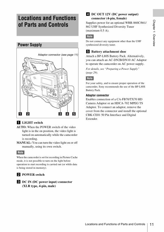
a LIGHT switchAUTO: When the POWER switch of the video
light is in the on position, the video light is turned on automatically while the camcorder is recording.
MANUAL: You can turn the video light on or off manually, using its own switch.
Note
When the camcorder is set for recording in Picture Cache mode, it is not possible to turn on the light before operation to start recording is carried out (or while data is being stored in memory).
b POWER switch
c DC IN (DC power input) connector (XLR type, 4-pin, male)
d DC OUT 12V (DC power output) connector (4-pin, female)
Supplies power for an optional WRR-860C/861/862 UHF Synthesized Diversity Tuner (maximum 0.5 A).
Note
Do not connect any equipment other than the UHF synthesized diversity tuner.
e Battery attachment shoeAttach a BP-L80S Battery Pack. Alternatively, you can attach an AC-DN2B/DN10 AC Adaptor to operate the camcorder on AC power supply.
For details, see “Preparing a Power Supply” (page 29).
Note
For your safety, and to ensure proper operation of the camcorder, Sony recommends the use of the BP-L80S Battery Pack.
Adaptor connectorEnables connection of a CA-FB70/TX70 HD Camera Adaptor or an HDCA-702 MPEG TS Adaptor. To connect an adaptor, remove the cover from the connector and install the optional CBK-CE01 50 Pin Interface and Digital Extender.
Locations and Functions of Parts and Controls
Power Supply
Adaptor connector (see page 11)
Locations and Functions of Parts and Controls 11
12
Chapter 1 O
verview
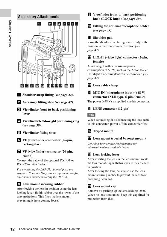
a Shoulder strap fitting (see page 42).
b Accessory fitting shoe (see page 42).
c Viewfinder front-to-back positioning lever
d Viewfinder left-to-right positioning ring (see page 30).
e Viewfinder fitting shoe
f VF (viewfinder) connector (26-pin, rectangular)
g VF (viewfinder) connector (20-pin, round)
Connect the cable of the optional DXF-51 or DXF-20W viewfinder.
For connecting the DXF-51, optional parts are required. Consult a Sony service representative for information about connecting the DXF-51.
h Lens mount securing rubberAfter locking the lens in position using the lens locking lever, fit this rubber over the lower of the two projections. This fixes the lens mount, preventing it from coming loose.
i Viewfinder front-to-back positioning knob (LOCK knob) (see page 30).
j Fitting for optional microphone holder (see page 39).
k Shoulder padRaise the shoulder pad fixing lever to adjust the position in the front-to-rear direction (see page 43).
l LIGHT (video light) connector (2-pin, female)
A video light with a maximum power consumption of 50 W, such as the Anton Bauer Ultralight 2 or equivalent can be connected (see page 42).
m Lens cable clamp
n MIC IN (microphone input) (+48 V) connector (XLR type, 5-pin, female)
The power (+48 V) is supplied via this connector.
o LENS connector (12-pin)
Note
When connecting or disconnecting the lens cable to this connector, power off the camcorder first.
p Tripod mount
q Lens mount (special bayonet mount)
Consult a Sony service representative for information about available lenses.
r Lens locking leverAfter inserting the lens in the lens mount, rotate the lens mount ring with this lever to lock the lens in position.After locking the lens, be sure to use the lens mount securing rubber to prevent the lens from becoming detached.
s Lens mount capRemove by pushing up the lens locking lever. When no lens is mounted, keep this cap fitted for protection from dust.
Accessory Attachments
Locations and Functions of Parts and Controls
Chapter 1 O
verview
Front
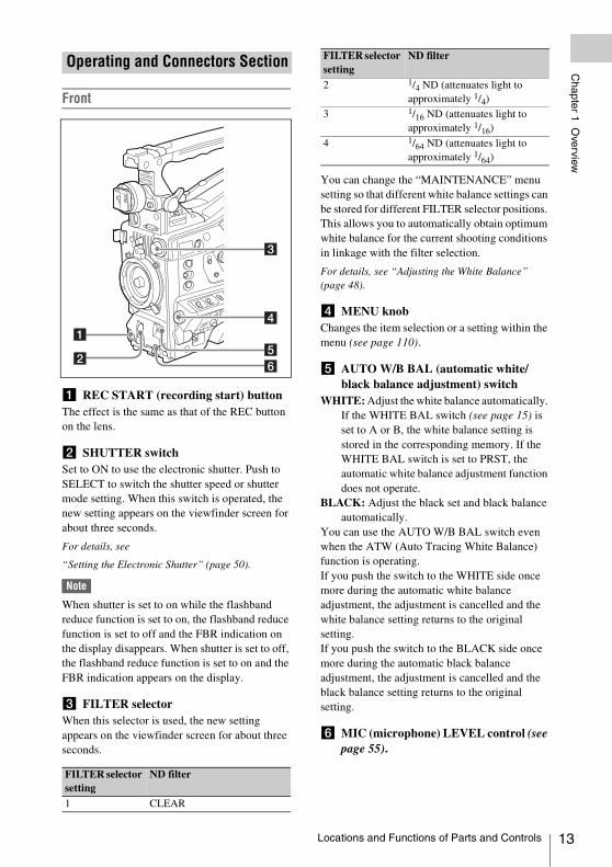
a REC START (recording start) buttonThe effect is the same as that of the REC button on the lens.
b SHUTTER switchSet to ON to use the electronic shutter. Push to SELECT to switch the shutter speed or shutter mode setting. When this switch is operated, the new setting appears on the viewfinder screen for about three seconds.
For details, see
“Setting the Electronic Shutter” (page 50).
Note
When shutter is set to on while the flashband reduce function is set to on, the flashband reduce function is set to off and the FBR indication on the display disappears. When shutter is set to off, the flashband reduce function is set to on and the FBR indication appears on the display.
c FILTER selectorWhen this selector is used, the new setting appears on the viewfinder screen for about three seconds.
You can change the “MAINTENANCE” menu setting so that different white balance settings can be stored for different FILTER selector positions. This allows you to automatically obtain optimum white balance for the current shooting conditions in linkage with the filter selection.
For details, see “Adjusting the White Balance” (page 48).
d MENU knobChanges the item selection or a setting within the menu (see page 110).
e AUTO W/B BAL (automatic white/black balance adjustment) switch
WHITE: Adjust the white balance automatically. If the WHITE BAL switch (see page 15) is set to A or B, the white balance setting is stored in the corresponding memory. If the WHITE BAL switch is set to PRST, the automatic white balance adjustment function does not operate.
BLACK: Adjust the black set and black balance automatically.
You can use the AUTO W/B BAL switch even when the ATW (Auto Tracing White Balance) function is operating.If you push the switch to the WHITE side once more during the automatic white balance adjustment, the adjustment is cancelled and the white balance setting returns to the original setting.If you push the switch to the BLACK side once more during the automatic black balance adjustment, the adjustment is cancelled and the black balance setting returns to the original setting.
f MIC (microphone) LEVEL control (see page 55).
Operating and Connectors Section
FILTER selector setting
ND filter
1 CLEAR
2 1/4 ND (attenuates light to approximately 1/4)
3 1/16 ND (attenuates light to approximately 1/16)
4 1/64 ND (attenuates light to approximately 1/64)
FILTER selector setting
ND filter
Locations and Functions of Parts and Controls 13
14
Chapter 1 O
verview
Right side (near the front)
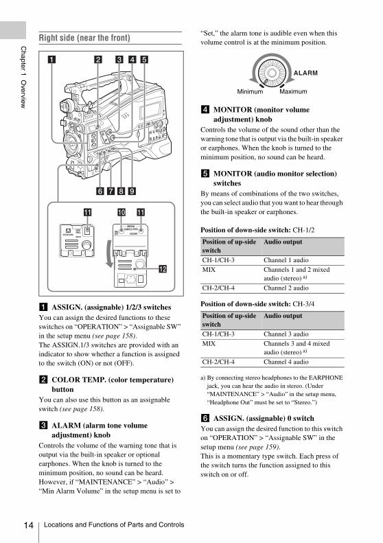
a ASSIGN. (assignable) 1/2/3 switchesYou can assign the desired functions to these switches on “OPERATION” > “Assignable SW” in the setup menu (see page 158).The ASSIGN.1/3 switches are provided with an indicator to show whether a function is assigned to the switch (ON) or not (OFF).
b COLOR TEMP. (color temperature) button
You can also use this button as an assignable switch (see page 158).
c ALARM (alarm tone volume adjustment) knob
Controls the volume of the warning tone that is output via the built-in speaker or optional earphones. When the knob is turned to the minimum position, no sound can be heard.However, if “MAINTENANCE” > “Audio” > “Min Alarm Volume” in the setup menu is set to
“Set,” the alarm tone is audible even when this volume control is at the minimum position.
d MONITOR (monitor volume adjustment) knob
Controls the volume of the sound other than the warning tone that is output via the built-in speaker or earphones. When the knob is turned to the minimum position, no sound can be heard.
e MONITOR (audio monitor selection) switches
By means of combinations of the two switches, you can select audio that you want to hear through the built-in speaker or earphones.
Position of down-side switch: CH-1/2
Position of down-side switch: CH-3/4
a) By connecting stereo headphones to the EARPHONE jack, you can hear the audio in stereo. (Under “MAINTENANCE” > “Audio” in the setup menu, “Headphone Out” must be set to “Stereo.”)
f ASSIGN. (assignable) 0 switchYou can assign the desired function to this switch on “OPERATION” > “Assignable SW” in the setup menu (see page 159).This is a momentary type switch. Each press of the switch turns the function assigned to this switch on or off.
Position of up-side switch
Audio output
CH-1/CH-3 Channel 1 audio
MIX Channels 1 and 2 mixed audio (stereo) a)
CH-2/CH-4 Channel 2 audio
Position of up-side switch
Audio output
CH-1/CH-3 Channel 3 audio
MIX Channels 3 and 4 mixed audio (stereo) a)
CH-2/CH-4 Channel 4 audio
ALARM
Minimum Maximum
Locations and Functions of Parts and Controls
Chapter 1 O
verview
g GAIN selectorSwitches the gain of the video amplifier to match the lighting conditions during shooting. The gains corresponding to the L, M, and H settings can be selected on “OPERATION” > “Gain Switch” in the setup menu (see page 121).When this switch is adjusted, the new setting appears on the viewfinder screen for about three seconds.
h OUTPUT/DCC (output signal/dynamic contrast control) switch
BARS: Output the color bar signal.CAM: Output the video signal being shot. When
this is selected, you can switch DCC 1) on and off.
1) DCC (Dynamic Contrast Control): Against a very bright background with the iris opening adjusted to the subject, objects in the background will be lost in the glare. The DCC function will suppress the high intensity and restore much of the lost detail and is particularly effective in the following cases.• Shooting people in the shade on a sunny day• Shooting a subject indoors, against a background
through a window• Any high contrast scene
i WHITE BAL (white balance memory) switch
PRST: Adjust the color temperature to the preset value (the factory default setting: 3200K). Use this setting when you have no time to adjust the white balance.
A or B: Recall the white balance adjustment settings already stored in A or B. Push the AUTO W/B BAL switch (see page 13) on the WHITE side, to automatically adjust the white balance, and save the adjustment settings in memory A or memory B.
B (ATW 1)): When this switch is set to B and “OPERATION” > “White Setting” > “White Switch<B>” is set to “ATW” in the setup menu, ATW is activated.You can use the AUTO W/B BAL switch even when ATW is in use.
When this switch is adjusted, the new setting appears on the viewfinder screen for about three seconds.1) ATW (Auto Tracing White Balance): The white
balance of the picture being shot is adjusted automatically for varying lighting conditions.
j MENU ON/OFF switchThis switch is used to display the menu on the viewfinder screen or the test signal screen. Each time the switch is pushed down, the menu screen is turned on and off.The function of this switch is the same as that of the MENU button in the thumbnail screen operations section.
k STATUS ON/SEL/OFF (menu display on/page selection/display off) switch
MENU CANCEL/PRST (preset) /ESCAPE switch
When the menu is not displayed, this switch functions as the STATUS ON/SEL/OFF switch. When the menu is displayed, the switch functions as the MENU CANCEL/PRST/ESCAPE switch. (To use the MENU CANCEL/PRST/ESCAPE switch, open the cover.)
Use the STATUS ON/SEL/OFF switch in the following way.ON/SEL: Each time this switch is pushed
upward, a window to confirm the menu settings and status of the camcorder appears on the viewfinder screen (see page 59). Each page is displayed for about 10 seconds.
OFF: To clear the page immediately after display, push this switch down to the OFF position.
Use the MENU CANCEL/PRST/ESCAPE switch in the following way.CANCEL/PRST: Pushing this switch up to this
position after a setting is changed in the setup menu displays the message to confirm whether the previous settings are cancelled. Pushing this switch up to this position again cancels the previous settings.Pushing this switch up to this position before a setting is changed in the setup menu or after a setting change is cancelled in the setup menu displays the message to confirm whether the setting is reset to the initial value.Pushing this switch up to this position again resets the settings to the initial value.
ESCAPE: Use this switch when the menu page, which has a hierarchical structure, is opened. Each time the switch is pushed to this position, the page returns to one stage higher in the hierarchy.
l Cover
Locations and Functions of Parts and Controls 15
16
Chapter 1 O
verview
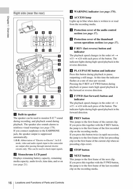
Right side (near the rear)
a Built-in speakerThe speaker can be used to monitor E-E 1) sound during recording, and playback sound during playback. The speaker also sounds alarms to reinforce visual warnings (see page 178).If you connect earphones to the EARPHONE jack, the speaker output is suppressed automatically.1) E-E: Abbreviation of “Electric-to-Electric”. In E-E
mode, video and audio signals input to the camcorder are output after passing through internal electric circuits only. This can be used to check input signals.
b Monochrome LCD panelDisplays remaining battery capacity, remaining media capacity, audio levels, time data, and so on (see page 21).
c WARNING indicator (see page 178).
d ACCESS lampLights up in blue when data is written to or read from the recording media.
e Protection cover of the audio control section (see page 17).
f Protection cover of the thumbnail screen operations section (see page 17).
g F REV (fast reverse) button and indicator
The playback speed changes in the order ×4 t ×15 t ×24 with each press of the button. The indicator lights during high-speed playback in the reverse direction.
h PLAY/PAUSE button and indicatorPress this button during playback to pause, outputting a still image. At this time the indicator flashes at a rate of once per second.Pressing the F REV or F FWD button during playback or pause starts high speed playback in the forward or reverse direction.
i F FWD (fast forward) button and indicator
The playback speed changes in the order ×4 t ×15 t ×24 with each press of the button. The indicator lights during high-speed playback in the forward direction.
j PREV buttonThis jumps to the first frame of the current clip. If you press this together with the F REV button, the jump is to the first frame of the first recorded clip on the recording media.If you press this button twice in rapid succession, the jump is to the first frame of the last preceding clip (or the first frame of the current clip when no preceding clips exist).
k STOP button
l NEXT buttonThis jumps to the first frame of the next clip.If you press this together with the F FWD button, the jump is to the first frame of the last recorded clip on the recording media.
Locations and Functions of Parts and Controls
Chapter 1 O
verview
m EXPAND (expand function) buttonIf you press this button when the thumbnail screen is displayed, the duration of the selected clip is divided into fractions, and the first frame of each of the divisions is shown in a further thumbnail display (expand function). For an HD recorded MP4 clip, its duration is divided into 12. If an SD recorded AVI clip comprises multiple files, the divisions are displayed for the individual files.For MP4 clips, each time you press this button the division is repeated. Hold down the SHIFT button and press this button to step back through the division process.
n HOLD (display hold) buttonPressing this button instantly freezes the time data displayed in the monochrome LCD panel. (The timecode generator continues running.) Pressing this button again releases the hold.
For details of the counter display, see page 21.
o RESET/RETURN buttonResets the value shown in the time counter display in the monochrome LCD panel. According to the settings of the PRESET/REGEN/CLOCK switch (see page 18) and the F-RUN/SET/R-RUN switch (see page 18), this button resets the display as follows.
a) Of the timecode bits for every frame recorded on the media, those bits which can be used to record useful information for the user such as scene number, shooting place, etc.
For details, see “Setting the Time Data” (page 56).
This button returns to the previous screen when pressed during thumbnail screen display, expand thumbnail screen display, or shot mark thumbnail screen display.
p DISPLAY switchThis cycles the data displayed in the time counter display in the monochrome LCD panel through the sequence COUNTER, TC, and U-BIT (see page 21).COUNTER: Display the elapsed recording/
playback time (hours, minutes, seconds, frames).
TC: Display timecode.U-BIT: Display user bits data.
q BACKLIGHT button
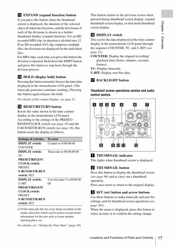
Thumbnail screen operations section and audio control section
a THUMBNAIL indicator This lights when thumbnail screen is displayed.
b THUMBNAIL buttonPress this button to display the thumbnail screen (see page 96) and to carry out a thumbnail operation.Press once more to return to the original display.
c SET (set) button and arrow buttonsUse these buttons to make timecode and user bit settings, and for thumbnail screen operations (see page 102).When the menu is displayed, press this button to select an item or to confirm the setting change.
Settings of switches To resetDISPLAY switch: COUNTER
Counter to 0:00:00:00
DISPLAY switch: TCPRESET/REGEN/CLOCK switch: PRESETF-RUN/SET/R-RUN switch: SET
Timecode to 00:00:00:00
DISPLAY switch: U-BITPRESET/REGEN/CLOCK switch: PRESETF-RUN/SET/R-RUN switch: SET
User bits data a) to 00 00 00 00
Locations and Functions of Parts and Controls 17
18
Chapter 1 O
verview
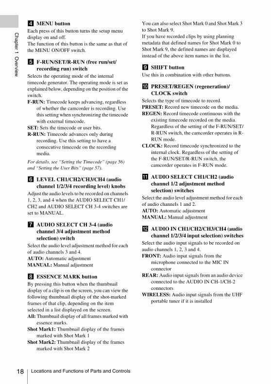
d MENU buttonEach press of this button turns the setup menu display on and off.The function of this button is the same as that of the MENU ON/OFF switch.
e F-RUN/SET/R-RUN (free run/set/recording run) switch
Selects the operating mode of the internal timecode generator. The operating mode is set as explained below, depending on the position of the switch.F-RUN: Timecode keeps advancing, regardless
of whether the camcorder is recording. Use this setting when synchronizing the timecode with external timecode.
SET: Sets the timecode or user bits.R-RUN: Timecode advances only during
recording. Use this setting to have a consecutive timecode on the recording media.
For details, see “Setting the Timecode” (page 56) and “Setting the User Bits” (page 57).
f LEVEL CH1/CH2/CH3/CH4 (audio channel 1/2/3/4 recording level) knobs
Adjust the audio levels to be recorded on channels 1, 2, 3, and 4 when the AUDIO SELECT CH1/CH2 and AUDIO SELECT CH 3-4 switches are set to MANUAL.
g AUDIO SELECT CH 3-4 (audio channel 3/4 adjustment method selection) switch
Select the audio level adjustment method for each of audio channels 3 and 4.AUTO: Automatic adjustmentMANUAL: Manual adjustment
h ESSENCE MARK buttonBy pressing this button when the thumbnail display of a clip is on the screen, you can view the following thumbnail display of the shot-marked frames of that clip, depending on the item selected in a list displayed on the screen.All: Thumbnail display of all frames marked with
essence marks.Shot Mark1: Thumbnail display of the frames
marked with Shot Mark 1Shot Mark2: Thumbnail display of the frames
marked with Shot Mark 2
You can also select Shot Mark 0 and Shot Mark 3 to Shot Mark 9.If you have recorded clips by using planning metadata that defined names for Shot Mark 0 to Shot Mark 9, the defined names are displayed instead of the above item names in the list.
i SHIFT buttonUse this in combination with other buttons.
j PRESET/REGEN (regeneration)/CLOCK switch
Selects the type of timecode to record.PRESET: Record new timecode on the media.REGEN: Record timecode continuous with the
existing timecode recorded on the media. Regardless of the setting of the F-RUN/SET/R-RUN switch, the camcorder operates in R-RUN mode.
CLOCK: Record timecode synchronized to the internal clock. Regardless of the setting of the F-RUN/SET/R-RUN switch, the camcorder operates in F-RUN mode.
k AUDIO SELECT CH1/CH2 (audio channel 1/2 adjustment method selection) switches
Select the audio level adjustment method for each of audio channels 1 and 2.AUTO: Automatic adjustmentMANUAL: Manual adjustment
l AUDIO IN CH1/CH2/CH3/CH4 (audio channel 1/2/3/4 input selection) switches
Select the audio input signals to be recorded on audio channels 1, 2, 3 and 4.FRONT: Audio input signals from the
microphone connected to the MIC IN connector
REAR: Audio input signals from an audio device connected to the AUDIO IN CH-1/CH-2 connectors
WIRELESS: Audio input signals from the UHF portable tuner if it is installed
Locations and Functions of Parts and Controls
Chapter 1 O
verview
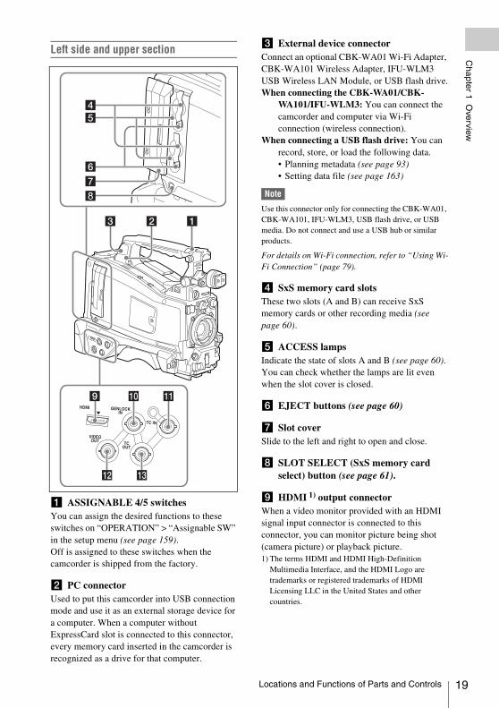
Left side and upper section
a ASSIGNABLE 4/5 switchesYou can assign the desired functions to these switches on “OPERATION” > “Assignable SW” in the setup menu (see page 159).Off is assigned to these switches when the camcorder is shipped from the factory.
b PC connectorUsed to put this camcorder into USB connection mode and use it as an external storage device for a computer. When a computer without ExpressCard slot is connected to this connector, every memory card inserted in the camcorder is recognized as a drive for that computer.
c External device connectorConnect an optional CBK-WA01 Wi-Fi Adapter, CBK-WA101 Wireless Adapter, IFU-WLM3 USB Wireless LAN Module, or USB flash drive.When connecting the CBK-WA01/CBK-
WA101/IFU-WLM3: You can connect the camcorder and computer via Wi-Fi connection (wireless connection).
When connecting a USB flash drive: You can record, store, or load the following data.• Planning metadata (see page 93)• Setting data file (see page 163)
Note
Use this connector only for connecting the CBK-WA01, CBK-WA101, IFU-WLM3, USB flash drive, or USB media. Do not connect and use a USB hub or similar products.
For details on Wi-Fi connection, refer to “Using Wi-Fi Connection” (page 79).
d SxS memory card slotsThese two slots (A and B) can receive SxS memory cards or other recording media (see page 60).
e ACCESS lampsIndicate the state of slots A and B (see page 60). You can check whether the lamps are lit even when the slot cover is closed.
f EJECT buttons (see page 60)
g Slot coverSlide to the left and right to open and close.
h SLOT SELECT (SxS memory card select) button (see page 61).
i HDMI 1) output connectorWhen a video monitor provided with an HDMI signal input connector is connected to this connector, you can monitor picture being shot (camera picture) or playback picture.1) The terms HDMI and HDMI High-Definition
Multimedia Interface, and the HDMI Logo are trademarks or registered trademarks of HDMI Licensing LLC in the United States and other countries.
HDMI GENLOCKIN
TC IN
VIDEOOUT TC
OUT
Locations and Functions of Parts and Controls 19
20
Chapter 1 O
verview
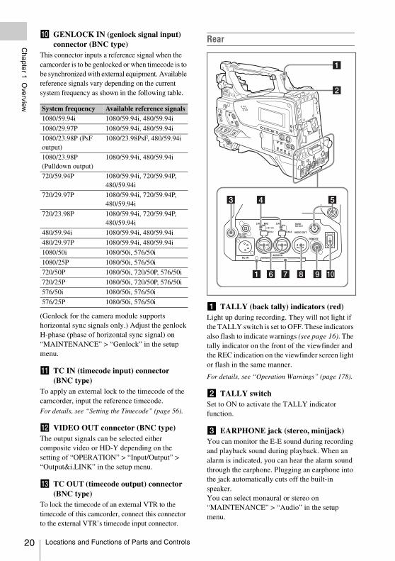
j GENLOCK IN (genlock signal input) connector (BNC type)
This connector inputs a reference signal when the camcorder is to be genlocked or when timecode is to be synchronized with external equipment. Available reference signals vary depending on the current system frequency as shown in the following table.
(Genlock for the camera module supports horizontal sync signals only.) Adjust the genlock H-phase (phase of horizontal sync signal) on “MAINTENANCE” > “Genlock” in the setup menu.
k TC IN (timecode input) connector (BNC type)
To apply an external lock to the timecode of the camcorder, input the reference timecode.For details, see “Setting the Timecode” (page 56).
l VIDEO OUT connector (BNC type)The output signals can be selected either composite video or HD-Y depending on the setting of “OPERATION” > “Input/Output” > “Output&i.LINK” in the setup menu.
m TC OUT (timecode output) connector (BNC type)
To lock the timecode of an external VTR to the timecode of this camcorder, connect this connector to the external VTR’s timecode input connector.
Rear
a TALLY (back tally) indicators (red)Light up during recording. They will not light if the TALLY switch is set to OFF. These indicators also flash to indicate warnings (see page 16). The tally indicator on the front of the viewfinder and the REC indication on the viewfinder screen light or flash in the same manner.
For details, see “Operation Warnings” (page 178).
b TALLY switchSet to ON to activate the TALLY indicator function.
c EARPHONE jack (stereo, minijack)You can monitor the E-E sound during recording and playback sound during playback. When an alarm is indicated, you can hear the alarm sound through the earphone. Plugging an earphone into the jack automatically cuts off the built-in speaker.You can select monaural or stereo on “MAINTENANCE” > “Audio” in the setup menu.
System frequency Available reference signals1080/59.94i 1080/59.94i, 480/59.94i
1080/29.97P 1080/59.94i, 480/59.94i
1080/23.98P (PsF output)
1080/23.98PsF, 480/59.94i
1080/23.98P (Pulldown output)
1080/59.94i, 480/59.94i
720/59.94P 1080/59.94i, 720/59.94P, 480/59.94i
720/29.97P 1080/59.94i, 720/59.94P, 480/59.94i
720/23.98P 1080/59.94i, 720/59.94P, 480/59.94i
480/59.94i 1080/59.94i, 480/59.94i
480/29.97P 1080/59.94i, 480/59.94i
1080/50i 1080/50i, 576/50i
1080/25P 1080/50i, 576/50i
720/50P 1080/50i, 720/50P, 576/50i
720/25P 1080/50i, 720/50P, 576/50i
576/50i 1080/50i, 576/50i
576/25P 1080/50i, 576/50i
Locations and Functions of Parts and Controls
Chapter 1 O
verview
d AUDIO IN selectorsSelect the audio source you connect to the AUDIO IN CH-1/CH-2 connectors.LINE: When connecting a stereo amplifier or
other external audio signal sourceMIC: When connecting a microphone that does
not require 48 V power supply+48V: When connecting a microphone that
requires 48 V power supply
e HD/SD SDI OUT connectors (BNC type)The PMW-400 has two HD/SD SDI OUT connectors. These connectors output an HDSDI or SDSDI signal (with embedded audio). The output from these connectors can be turned on or off, on “OPERATION” > “Input/Output” > “SDI Output” in the setup menu.
f AUDIO IN CH-1/CH-2 (audio channel 1 and channel 2 input) connectors (XLR type, 3-pin, female)
You can connect audio equipment or a microphone.
g Bottom coverThis is provided for protecting the cables connected to the connectors on the rear panel.By loosening the screws which retain the cover to the bottom of the camcorder, you can adjust the position of the cover depending on the size and shape of the microphone or audio cable plugs.After adjusting the position, tighten the screws to secure the cover.
h AUDIO OUT connector (XLR type, 5-pin, male)
Outputs the audio signals recorded on audio channels 1 and 2 or audio channels 3 and 4. The audio signals are selected by the MONITOR switch.
i REMOTE connector (8-pin)
Note
Before connecting/disconnecting the Remote Control Unit to/from the camcorder, be sure to turn off the camcorder POWER switch.
j i.LINK (HDV/DV) connector (6-pin, IEEE1394 compliant, S400)
To input and output HDV/DV streams, connect to an HDV/DV device.
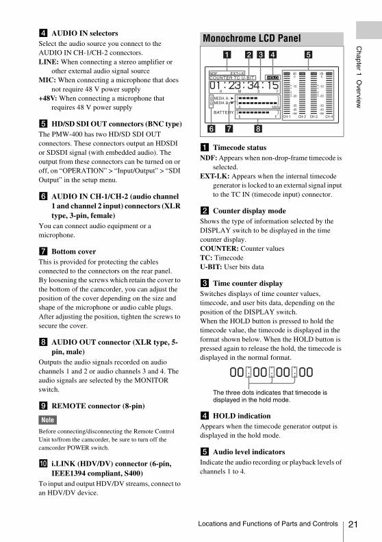
a Timecode statusNDF: Appears when non-drop-frame timecode is
selected.EXT-LK: Appears when the internal timecode
generator is locked to an external signal input to the TC IN (timecode input) connector.
b Counter display modeShows the type of information selected by the DISPLAY switch to be displayed in the time counter display.COUNTER: Counter valuesTC: TimecodeU-BIT: User bits data
c Time counter displaySwitches displays of time counter values, timecode, and user bits data, depending on the position of the DISPLAY switch.When the HOLD button is pressed to hold the timecode value, the timecode is displayed in the format shown below. When the HOLD button is pressed again to release the hold, the timecode is displayed in the normal format.
d HOLD indicationAppears when the timecode generator output is displayed in the hold mode.
e Audio level indicatorsIndicate the audio recording or playback levels of channels 1 to 4.
Monochrome LCD Panel
The three dots indicates that timecode is displayed in the hold mode.
Locations and Functions of Parts and Controls 21
22
Chapter 1 O
verview
f Lock iconAppears when the recording media is write-protected.
g Remaining media capacity indicatorShows bar segments indicating the remaining capacity of recording media in the slots.
h Remaining battery capacity indicatorShows bar segments indicating the remaining battery capacity.
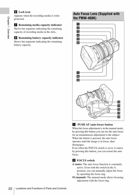
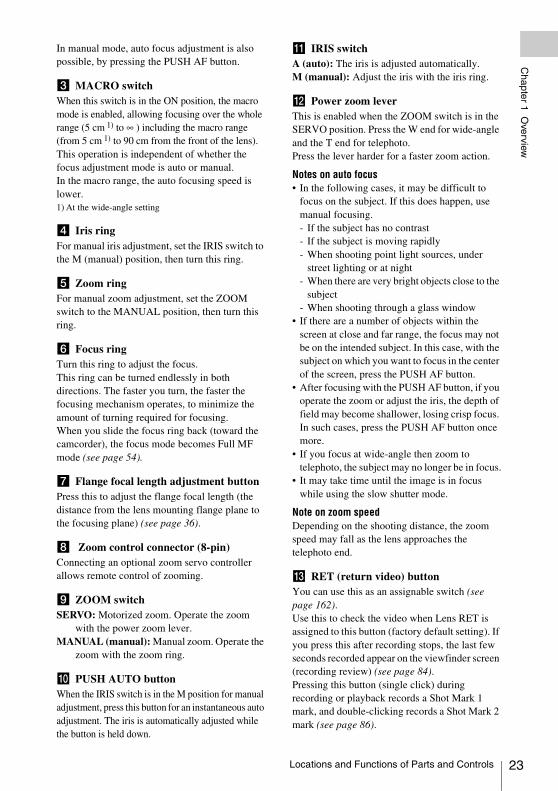
a PUSH AF (auto focus) buttonWhen the focus adjustment is in the manual mode, by pressing this button you can use the auto focus for an instantaneous adjustment to the subject.When the button is pressed, the auto focus operates until the image is in focus, then disengages.Even when the FOCUS switch is set to A (auto), by pressing this button, you can restart the auto focus.
b FOCUS switchA (auto): The auto focus function is constantly
active. Even with the switch in the A position, you can manually adjust the focus by operating the focus ring.
M (manual): The manual mode allows focusing adjustment with the focus ring.
Auto Focus Lens (Supplied with the PMW-400K)
Locations and Functions of Parts and Controls
Chapter 1 O
verview
In manual mode, auto focus adjustment is also possible, by pressing the PUSH AF button.
c MACRO switchWhen this switch is in the ON position, the macro mode is enabled, allowing focusing over the whole range (5 cm 1) to ∞ ) including the macro range (from 5 cm 1) to 90 cm from the front of the lens).This operation is independent of whether the focus adjustment mode is auto or manual.In the macro range, the auto focusing speed is lower.1) At the wide-angle setting
d Iris ringFor manual iris adjustment, set the IRIS switch to the M (manual) position, then turn this ring.
e Zoom ringFor manual zoom adjustment, set the ZOOM switch to the MANUAL position, then turn this ring.
f Focus ringTurn this ring to adjust the focus.This ring can be turned endlessly in both directions. The faster you turn, the faster the focusing mechanism operates, to minimize the amount of turning required for focusing.When you slide the focus ring back (toward the camcorder), the focus mode becomes Full MF mode (see page 54).
g Flange focal length adjustment buttonPress this to adjust the flange focal length (the distance from the lens mounting flange plane to the focusing plane) (see page 36).
h Zoom control connector (8-pin)Connecting an optional zoom servo controller allows remote control of zooming.
i ZOOM switchSERVO: Motorized zoom. Operate the zoom
with the power zoom lever.MANUAL (manual): Manual zoom. Operate the
zoom with the zoom ring.
j PUSH AUTO buttonWhen the IRIS switch is in the M position for manual adjustment, press this button for an instantaneous auto adjustment. The iris is automatically adjusted while the button is held down.
k IRIS switchA (auto): The iris is adjusted automatically.M (manual): Adjust the iris with the iris ring.
l Power zoom leverThis is enabled when the ZOOM switch is in the SERVO position. Press the W end for wide-angle and the T end for telephoto.Press the lever harder for a faster zoom action.
Notes on auto focus• In the following cases, it may be difficult to
focus on the subject. If this does happen, use manual focusing.- If the subject has no contrast- If the subject is moving rapidly- When shooting point light sources, under
street lighting or at night- When there are very bright objects close to the
subject- When shooting through a glass window
• If there are a number of objects within the screen at close and far range, the focus may not be on the intended subject. In this case, with the subject on which you want to focus in the center of the screen, press the PUSH AF button.
• After focusing with the PUSH AF button, if you operate the zoom or adjust the iris, the depth of field may become shallower, losing crisp focus. In such cases, press the PUSH AF button once more.
• If you focus at wide-angle then zoom to telephoto, the subject may no longer be in focus.
• It may take time until the image is in focus while using the slow shutter mode.
Note on zoom speedDepending on the shooting distance, the zoom speed may fall as the lens approaches the telephoto end.
m RET (return video) buttonYou can use this as an assignable switch (see page 162).Use this to check the video when Lens RET is assigned to this button (factory default setting). If you press this after recording stops, the last few seconds recorded appear on the viewfinder screen (recording review) (see page 84).Pressing this button (single click) during recording or playback records a Shot Mark 1 mark, and double-clicking records a Shot Mark 2 mark (see page 86).
Locations and Functions of Parts and Controls 23
24
Chapter 1 O
verview
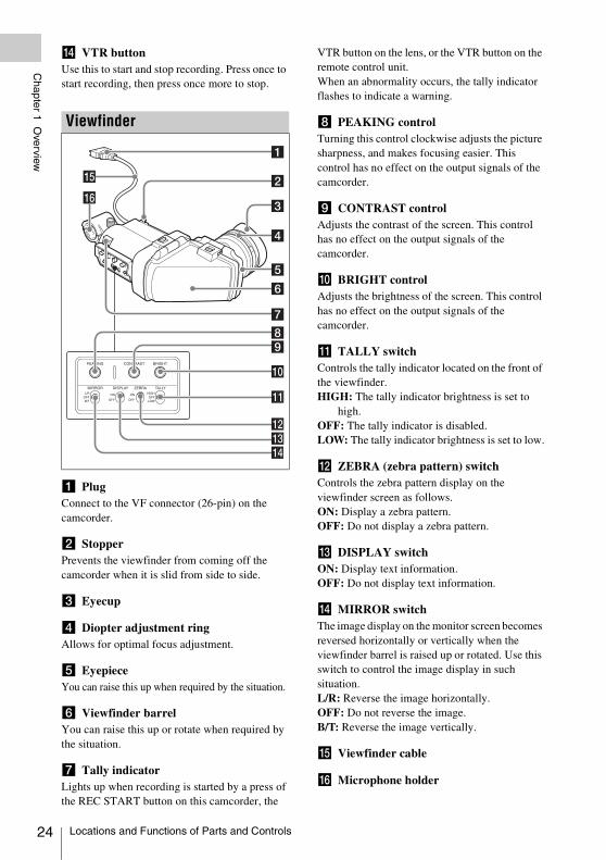
n VTR buttonUse this to start and stop recording. Press once to start recording, then press once more to stop.
a PlugConnect to the VF connector (26-pin) on the camcorder.
b StopperPrevents the viewfinder from coming off the camcorder when it is slid from side to side.
c Eyecup
d Diopter adjustment ringAllows for optimal focus adjustment.
e EyepieceYou can raise this up when required by the situation.
f Viewfinder barrelYou can raise this up or rotate when required by the situation.
g Tally indicatorLights up when recording is started by a press of the REC START button on this camcorder, the
VTR button on the lens, or the VTR button on the remote control unit.When an abnormality occurs, the tally indicator flashes to indicate a warning.
h PEAKING controlTurning this control clockwise adjusts the picture sharpness, and makes focusing easier. This control has no effect on the output signals of the camcorder.
i CONTRAST controlAdjusts the contrast of the screen. This control has no effect on the output signals of the camcorder.
j BRIGHT controlAdjusts the brightness of the screen. This control has no effect on the output signals of the camcorder.
k TALLY switchControls the tally indicator located on the front of the viewfinder.HIGH: The tally indicator brightness is set to
high.OFF: The tally indicator is disabled.LOW: The tally indicator brightness is set to low.
l ZEBRA (zebra pattern) switchControls the zebra pattern display on the viewfinder screen as follows.ON: Display a zebra pattern.OFF: Do not display a zebra pattern.
m DISPLAY switchON: Display text information.OFF: Do not display text information.
n MIRROR switchThe image display on the monitor screen becomes reversed horizontally or vertically when the viewfinder barrel is raised up or rotated. Use this switch to control the image display in such situation.L/R: Reverse the image horizontally.OFF: Do not reverse the image.B/T: Reverse the image vertically.
o Viewfinder cable
p Microphone holder
Viewfinder
Locations and Functions of Parts and Controls
Chapter 1 O
verview
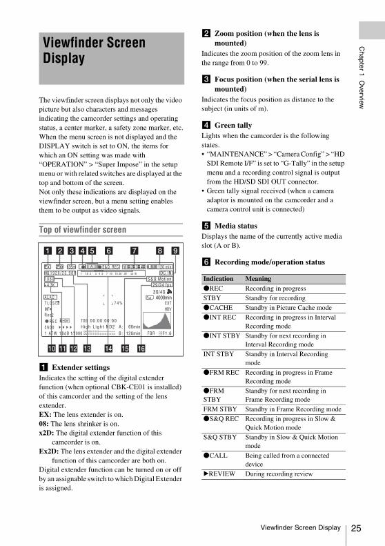
The viewfinder screen displays not only the video picture but also characters and messages indicating the camcorder settings and operating status, a center marker, a safety zone marker, etc.When the menu screen is not displayed and the DISPLAY switch is set to ON, the items for which an ON setting was made with “OPERATION” > “Super Impose” in the setup menu or with related switches are displayed at the top and bottom of the screen.Not only these indications are displayed on the viewfinder screen, but a menu setting enables them to be output as video signals.Top of viewfinder screen
a Extender settingsIndicates the setting of the digital extender function (when optional CBK-CE01 is installed) of this camcorder and the setting of the lens extender.EX: The lens extender is on.08: The lens shrinker is on.x2D: The digital extender function of this
camcorder is on.Ex2D: The lens extender and the digital extender
function of this camcorder are both on.Digital extender function can be turned on or off by an assignable switch to which Digital Extender is assigned.
b Zoom position (when the lens is mounted)
Indicates the zoom position of the zoom lens in the range from 0 to 99.
c Focus position (when the serial lens is mounted)
Indicates the focus position as distance to the subject (in units of m).
d Green tallyLights when the camcorder is the following states.• “MAINTENANCE” > “Camera Config” > “HD
SDI Remote I/F” is set to “G-Tally” in the setup menu and a recording control signal is output from the HD/SD SDI OUT connector.
• Green tally signal received (when a camera adaptor is mounted on the camcorder and a camera control unit is connected)
e Media statusDisplays the name of the currently active media slot (A or B).
f Recording mode/operation status
Viewfinder Screen Display
Indication MeaningzREC Recording in progress
STBY Standby for recording
zCACHE Standby in Picture Cache mode
zINT REC Recording in progress in Interval Recording mode
zINT STBY Standby for next recording in Interval Recording mode
INT STBY Standby in Interval Recording mode
zFRM REC Recording in progress in Frame Recording mode
zFRM STBY
Standby for next recording in Frame Recording mode
FRM STBY Standby in Frame Recording mode
zS&Q REC Recording in progress in Slow & Quick Motion mode
S&Q STBY Standby in Slow & Quick Motion mode
zCALL Being called from a connected device
BREVIEW During recording review
Viewfinder Screen Display 25
26
Chapter 1 O
verview
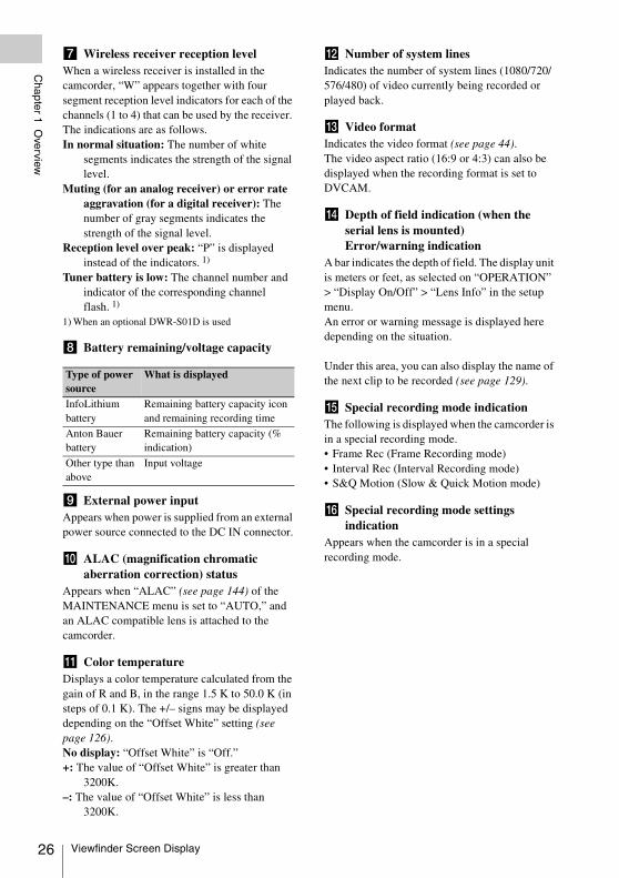
g Wireless receiver reception levelWhen a wireless receiver is installed in the camcorder, “W” appears together with four segment reception level indicators for each of the channels (1 to 4) that can be used by the receiver. The indications are as follows.In normal situation: The number of white
segments indicates the strength of the signal level.
Muting (for an analog receiver) or error rate aggravation (for a digital receiver): The number of gray segments indicates the strength of the signal level.
Reception level over peak: “P” is displayed instead of the indicators. 1)
Tuner battery is low: The channel number and indicator of the corresponding channel flash. 1)
1) When an optional DWR-S01D is used
h Battery remaining/voltage capacity
i External power inputAppears when power is supplied from an external power source connected to the DC IN connector.
j ALAC (magnification chromatic aberration correction) status
Appears when “ALAC” (see page 144) of the MAINTENANCE menu is set to “AUTO,” and an ALAC compatible lens is attached to the camcorder.
k Color temperatureDisplays a color temperature calculated from the gain of R and B, in the range 1.5 K to 50.0 K (in steps of 0.1 K). The +/– signs may be displayed depending on the “Offset White” setting (see page 126).No display: “Offset White” is “Off.”+: The value of “Offset White” is greater than
3200K.–: The value of “Offset White” is less than
3200K.
l Number of system linesIndicates the number of system lines (1080/720/576/480) of video currently being recorded or played back.
m Video formatIndicates the video format (see page 44).The video aspect ratio (16:9 or 4:3) can also be displayed when the recording format is set to DVCAM.
n Depth of field indication (when the serial lens is mounted) Error/warning indication
A bar indicates the depth of field. The display unit is meters or feet, as selected on “OPERATION” > “Display On/Off” > “Lens Info” in the setup menu.An error or warning message is displayed here depending on the situation.
Under this area, you can also display the name of the next clip to be recorded (see page 129).
o Special recording mode indicationThe following is displayed when the camcorder is in a special recording mode.• Frame Rec (Frame Recording mode)• Interval Rec (Interval Recording mode)• S&Q Motion (Slow & Quick Motion mode)
p Special recording mode settings indication
Appears when the camcorder is in a special recording mode.
Type of power source
What is displayed
InfoLithium battery
Remaining battery capacity icon and remaining recording time
Anton Bauer battery
Remaining battery capacity (% indication)
Other type than above
Input voltage
Viewfinder Screen Display
Chapter 1 O
verview
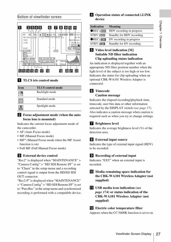
Bottom of viewfinder screen
a TLCS iris control mode
b Focus adjustment mode (when the auto focus lens is mounted)
Indicates the current focus adjustment mode of the camcorder.• AF (Auto Focus mode)• MF (Manual Focus mode)• MF* (Manual Focus mode when the MF Assist
function is on)• Full MF (Full Manual Focus mode)
c External device control“Rec2” is displayed when “MAINTENANCE” > “Camera Config” > “HD SDI Remote I/F” is set to “Chara” in the setup menu and a recording control signal is output from the HD/SD SDI OUT connector.“Rec2-P” is displayed when “MAINTENANCE” > “Camera Config” > “HD SDI Remote I/F” is set to “Para Rec” in the setup menu and synchronized recording is performed with a compatible device.
d Operation status of connected i.LINK device
e Video level indication [M]Suitable ND filter indicationClip uploading status indication
An indication is displayed together with an appropriate ND filter position number when the light level of the subject is too high or too low.Indicates the status for clip uploading when an optional CBK-WA101 Wireless Adapter is connected.
f Timecode Caution message
Indicates the elapsed recording/playback time, timecode, user bits data or other information selected by the DISPLAY switch (see page 17).Also indicates a caution message when caution is required such as when you try to change settings.
g Brightness levelIndicates the average brightness level (%) of the detection area.
h External input sourceIndicates the type of external input signal (HDV) to be recorded.
i Recording of external inputIndicates “EXT” when an external input is recorded.
j Media remaining space indication for the CBK-WA101 Wireless Adapter (not supplied)
k USB media icon indication (see page 174) or status indication of the CBK-WA101 Wireless Adapter (not supplied)
l Electric color temperature filterAppears when the CC 5600K function is set to on.
Icon TLCS control modeBacklight mode
Standard mode
Spotlight mode
STDSTD
Indication MeaningzREC HDV recording in progress
STBY Standby for HDV recording
zREC DV recording in progress
STBY Standby for DV recording
Viewfinder Screen Display 27
28
Chapter 1 O
verview
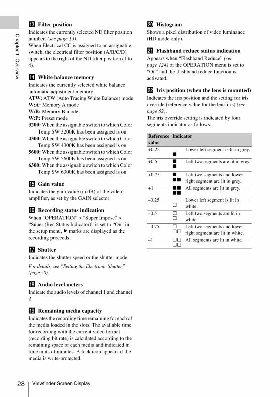
m Filter positionIndicates the currently selected ND filter position number. (see page 13).When Electrical CC is assigned to an assignable switch, the electrical filter position (A/B/C/D) appears to the right of the ND filter position (1 to 4).
n White balance memoryIndicates the currently selected white balance automatic adjustment memory.ATW: ATW (Auto Tracing White Balance) modeW:A: Memory A modeW:B: Memory B modeW:P: Preset mode3200: When the assignable switch to which Color
Temp SW 3200K has been assigned is on4300: When the assignable switch to which Color
Temp SW 4300K has been assigned is on 5600: When the assignable switch to which Color
Temp SW 5600K has been assigned is on6300: When the assignable switch to which Color
Temp SW 6300K has been assigned is on
o Gain valueIndicates the gain value (in dB) of the video amplifier, as set by the GAIN selector.
p Recording status indicationWhen “OPERATION” > “Super Impose” > “Super (Rec Status Indicator)” is set to “On” in the setup menu, B marks are displayed as the recording proceeds.
q ShutterIndicates the shutter speed or the shutter mode.
For details, see “Setting the Electronic Shutter” (page 50).
r Audio level metersIndicate the audio levels of channel 1 and channel 2.
s Remaining media capacityIndicates the recording time remaining for each of the media loaded in the slots. The available time for recording with the current video format (recording bit rate) is calculated according to the remaining space of each media and indicated in time units of minutes. A lock icon appears if the media is write-protected.
t HistogramShows a pixel distribution of video luminance (HD mode only).
u Flashband reduce status indicationAppears when “Flashband Reduce” (see page 124) of the OPERATION menu is set to “On” and the flashband reduce function is activated.
v Iris position (when the lens is mounted)Indicates the iris position and the setting for iris override (reference value for the lens iris) (see page 52).The iris override setting is indicated by four segments indicator as follows.
Reference value
Indicator
+0.25x
Lower left segment is lit in grey.
+0.5 xx
Left two segments are lit in grey.
+0.75 x
xx
Left two segments and lower right segment are lit in grey.
+1 xx
xx
All segments are lit in grey.
–0.25s
Lower left segment is lit in white.
–0.5 ss
Left two segments are lit in white.
–0.75 s
ss
Left two segments and lower right segment are lit in white.
–1 ss
ss
All segments are lit in white.
Viewfinder Screen Display
Chapter 2 P
reparations
For safety, use only the Sony battery packs and AC adaptors listed below.• BP-L80S Lithium-ion Battery Pack
When a BP-L80S Battery Pack is used, the camcorder can be operated continuously for approximately 270 minutes.
• AC power using the AC-DN2B/DN10 AC Adaptor
• The fan and battery are consumable parts that will need periodic replacement.When operating at room temperature, a normal replacement cycle will be about 5 to 7 years.However, this replacement cycle represents only a general guideline and does not imply that the life expectancy of these parts is guaranteed. For details on parts replacement, contact your dealer.
• The life expectancy of the AC adapter and the electrolytic capacitor is about 5 years under normal operating temperatures and normal usage (8 hours per day; 25 days per month). If usage exceeds the above normal usage frequency, the life expectancy may be reduced correspondingly.
The battery terminal of this unit (the connector for battery packs and AC adaptors) is a consumable part.• Power may not be supplied to the unit properly
if the pins of the battery terminal are bent or deformed by shock or vibrations, or if they become corroded due to prolonged outdoor use.Periodic inspections are recommended to keep the unit working properly and to prolong its usable lifetime.Contact a Sony service or sales representative for more information about inspections.
Press the battery pack against the back of the camcorder, aligning the line on the side of the battery pack with the line on the camcorder. Then slide the battery pack down until its “LOCK” arrow aligns with the line on the camcorder.To detach the battery pack, pull the battery pack up by holding the release button in.
WARNING
Batteries shall not be exposed to excessive heat such as sunshine, fire or the like.
Note
The battery pack operating time depends on the frequency of use of the battery pack, and the ambient temperature when used.
Before use, charge the battery pack with a charger suitable for each battery.
For details on the battery charging procedure, refer to the battery charger operation manual.
Note on using the battery packA warm battery pack may not be able to be fully recharged.
Notes
• If the battery pack is not attached correctly, the terminal may be damaged.
• During recording and playback (while the ACCESS lamp on the right-side panel is lit in blue and the ACCESS lamp in the card slot section is lit in orange), be careful never to remove the battery pack.
• Make sure to power the camcorder off before replacing the battery pack.
Mount an AC-DN2B/DN10 on the camcorder in the same way as a battery pack, then connect to the AC power supply.The AC-DN2B/DN10 can supply up to 100 W of power.
Chapter2 Preparations
Preparing a Power Supply
Using a Battery Pack
Using AC Power
Preparing a Power Supply 29
30
Chapter 2 P
reparations
CAUTION
When the viewfinder is attached, do not leave the camcorder with the eyepiece facing the sun. Direct sunlight can enter through the eyepiece, be focused in the viewfinder and cause fire.
Note
When attaching the viewfinder, make notes of the following points.• Be sure to power off the camcorder before coupling the
viewfinder connector to the camcorder’s VF connector (26-pin). If you make this connection when the camcorder power is on, the viewfinder may not function properly.
• Couple the viewfinder connector firmly to the camcorder’s VF connector (26-pin). If the coupling is loose, noise may appear on the video or the tally indicator may not operate properly.
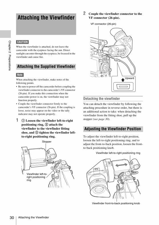
1 1 Loosen the viewfinder left-to-right positioning ring, 2 attach the viewfinder to the viewfinder fitting shoe, and 3 tighten the viewfinder left-to-right positioning ring.
2 Couple the viewfinder connector to the VF connector (26-pin).
Detaching the viewfinderYou can detach the viewfinder by following the attaching procedure in reverse order, but there is an additional action to take: when detaching the viewfinder from the fitting shoe, pull up the stopper (see page 30).
To adjust the viewfinder left-to-right position, loosen the left-to-right positioning ring, and to adjust the front-to-back position, loosen the front-to-back positioning knob.
Attaching the Viewfinder
Attaching the Supplied Viewfinder
Stopper
Viewfinder left-to-right positioning ring
Adjusting the Viewfinder Position
VF connector (26-pin)
Upward
Viewfinder front-to-back positioning knob
Viewfinder left-to-right positioning ring
Attaching the Viewfinder
Chapter 2 P
reparations
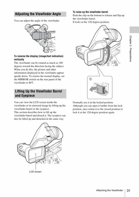
You can adjust the angle of the viewfinder.
To reverse the display (image/text indication) verticallyThe viewfinder can be rotated as much as 180 degrees toward the direction facing the subject.When you do this, the picture and other information displayed in the viewfinder appear upside down. To restore the normal display, set the MIRROR switch on the rear panel of the viewfinder to B/T.
You can view the LCD screen inside the viewfinder or its mirrored image by lifting up the viewfinder barrel or the eyepiece.This section describes how to lift up the viewfinder barrel and detach it. The eyepiece can also be lifted up and detached in the same way.
To raise up the viewfinder barrelPush the clip on the bottom to release and flip up the viewfinder barrel.It locks at the 120-degree position.
Normally use it in the locked position.Although you can open it farther from the lock position, once return it to the closed position to lock it at the 120-degree position again.
Adjusting the Viewfinder Angle
Lifting Up the Viewfinder Barrel and Eyepiece
LCD screen
Attaching the Viewfinder 31
32
Chapter 2 P
reparations
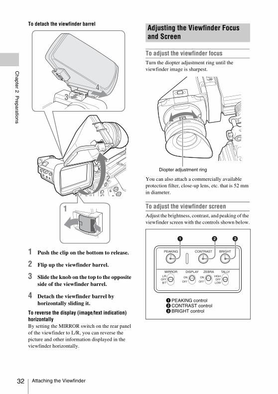
To detach the viewfinder barrel
1 Push the clip on the bottom to release.
2 Flip up the viewfinder barrel.
3 Slide the knob on the top to the opposite side of the viewfinder barrel.
4 Detach the viewfinder barrel by horizontally sliding it.
To reverse the display (image/text indication) horizontallyBy setting the MIRROR switch on the rear panel of the viewfinder to L/R, you can reverse the picture and other information displayed in the viewfinder horizontally.
To adjust the viewfinder focusTurn the diopter adjustment ring until the viewfinder image is sharpest.
You can also attach a commercially available protection filter, close-up lens, etc. that is 52 mm in diameter.
To adjust the viewfinder screenAdjust the brightness, contrast, and peaking of the viewfinder screen with the controls shown below.
Adjusting the Viewfinder Focus and Screen
Diopter adjustment ring
1PEAKING control2CONTRAST control3BRIGHT control
Attaching the Viewfinder
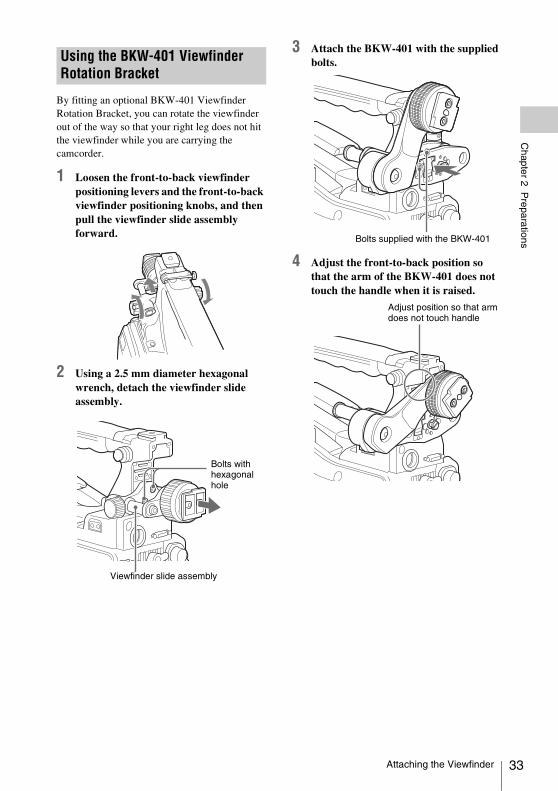
Chapter 2 P
reparations
By fitting an optional BKW-401 Viewfinder Rotation Bracket, you can rotate the viewfinder out of the way so that your right leg does not hit the viewfinder while you are carrying the camcorder.
1 Loosen the front-to-back viewfinder positioning levers and the front-to-back viewfinder positioning knobs, and then pull the viewfinder slide assembly forward.
2 Using a 2.5 mm diameter hexagonal wrench, detach the viewfinder slide assembly.
3 Attach the BKW-401 with the supplied bolts.
4 Adjust the front-to-back position so that the arm of the BKW-401 does not touch the handle when it is raised.
Using the BKW-401 Viewfinder Rotation Bracket
Bolts with hexagonal hole
Viewfinder slide assembly
Bolts supplied with the BKW-401
Adjust position so that arm does not touch handle
Attaching the Viewfinder 33
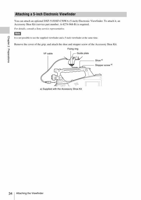
34
Chapter 2 P
reparations
You can attach an optional DXF-51/DXF-C50WA (5-inch) Electronic Viewfinder. To attach it, an Accessory Shoe Kit (service part number: A-8274-968-B) is required.
For details, consult a Sony service representative.
Note
It is not possible to use the supplied viewfinder and a 5-inch viewfinder at the same time.
Remove the cover of the grip, and attach the shoe and stopper screw of the Accessory Shoe Kit.
Attaching a 5-inch Electronic Viewfinder
VF cable
Fixing ring
Guide plate
Shoe a)
Stopper screw a)
a) Supplied with the Accessory Shoe Kit
Attaching the Viewfinder
Chapter 2 P
reparations
When using the camcorder for the first timeYou cannot use the camcorder without setting the area of use.
To set the area of use
1 Set the POWER switch to the ON position.The screen for setting the area of use appears in the viewfinder.
2 Press the MENU knob.The settings for selectable areas of use are displayed.
3 Turn the MENU knob to select the desired area of use.
a) The composite signal output from this camcorder is an NTSC signal with a black setup (7.5 IRE). The system frequency is 59.94i.
b) The composite signal output from this camcorder is an NTSC signal with no black setup. The system frequency is 59.94i.
c) The composite signal output from this camcorder is a PAL signal. The system frequency is 50i.
4 Set the following items.• Time Zone• Date/Time
See “Basic Setup Menu Operations” (page 110).
5 Turn the MENU knob to select “Finish”, then press the MENU knob.The camcorder is now ready for use.
You can set or change the date and time of the internal clock. The date and time set are reflected in the timecode.
For menu operations, see “Basic Setup Menu Operations” (page 110).
1 Select “MAINTENANCE” > “Clock Set” > “Date/Time” in the setup menu.
2 Press the MENU knob.The Date/Time setting window appears.
3 Turn the MENU knob to display the desired value, and press the knob.The selection shifts to the next item on the right.
4 To continue the remaining settings, repeat step 3.
5 Making sure that “SET” is selected, press the MENU knob.The internal clock is set with the date and time set in steps 3 and 4.
To cancel the settingBefore executing step 5, push the MENU CANCEL/PRST/ESCAPE switch up to the CANCEL/PRST side.
Setting the Area of Use
Setting Area of useNTSC Area NTSC area (for areas other
than Japan) a)
NTSC(J) Area NTSC area (Japan) b)
PAL Area PAL area c)
Setting the Date/Time of the Internal Clock
Setting the Area of Use / Setting the Date/Time of the Internal Clock 35
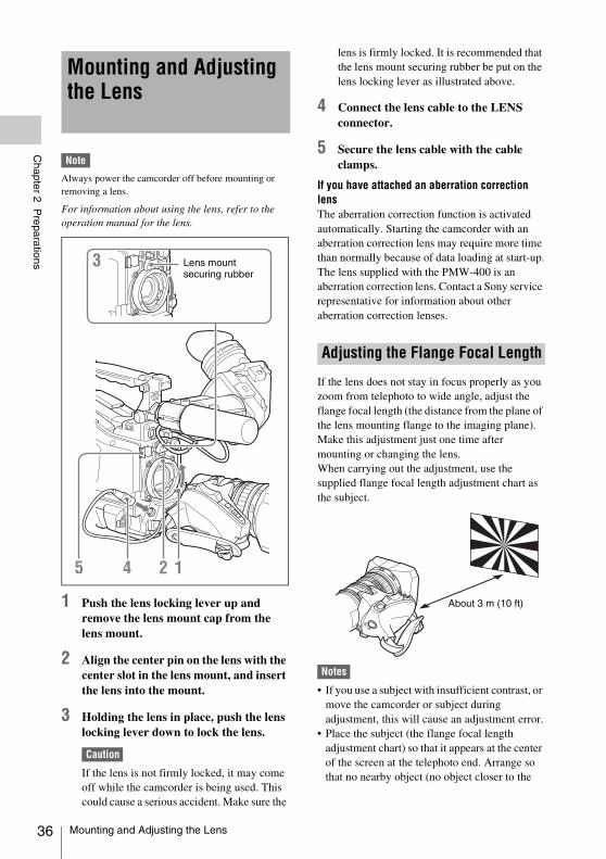
36
Chapter 2 P
reparations
Note
Always power the camcorder off before mounting or removing a lens.
For information about using the lens, refer to the operation manual for the lens.
1 Push the lens locking lever up and remove the lens mount cap from the lens mount.
2 Align the center pin on the lens with the center slot in the lens mount, and insert the lens into the mount.
3 Holding the lens in place, push the lens locking lever down to lock the lens.
Caution
If the lens is not firmly locked, it may come off while the camcorder is being used. This could cause a serious accident. Make sure the
lens is firmly locked. It is recommended that the lens mount securing rubber be put on the lens locking lever as illustrated above.
4 Connect the lens cable to the LENS connector.
5 Secure the lens cable with the cable clamps.
If you have attached an aberration correction lensThe aberration correction function is activated automatically. Starting the camcorder with an aberration correction lens may require more time than normally because of data loading at start-up.The lens supplied with the PMW-400 is an aberration correction lens. Contact a Sony service representative for information about other aberration correction lenses.
If the lens does not stay in focus properly as you zoom from telephoto to wide angle, adjust the flange focal length (the distance from the plane of the lens mounting flange to the imaging plane). Make this adjustment just one time after mounting or changing the lens.When carrying out the adjustment, use the supplied flange focal length adjustment chart as the subject.
Notes
• If you use a subject with insufficient contrast, or move the camcorder or subject during adjustment, this will cause an adjustment error.
• Place the subject (the flange focal length adjustment chart) so that it appears at the center of the screen at the telephoto end. Arrange so that no nearby object (no object closer to the
Mounting and Adjusting the Lens
Lens mount securing rubber
Adjusting the Flange Focal Length
About 3 m (10 ft)
Mounting and Adjusting the Lens
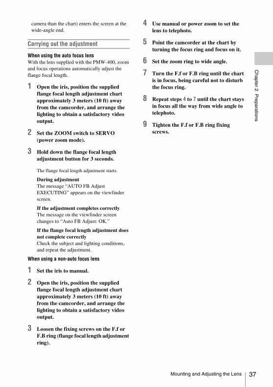
Chapter 2 P
reparations
camera than the chart) enters the screen at the wide-angle end.
Carrying out the adjustment
When using the auto focus lensWith the lens supplied with the PMW-400, zoom and focus operations automatically adjust the flange focal length.
1 Open the iris, position the supplied flange focal length adjustment chart approximately 3 meters (10 ft) away from the camcorder, and arrange the lighting to obtain a satisfactory video output.
2 Set the ZOOM switch to SERVO (power zoom mode).
3 Hold down the flange focal length adjustment button for 3 seconds.
The flange focal length adjustment starts.
During adjustmentThe message “AUTO FB Adjust EXECUTING” appears on the viewfinder screen.
If the adjustment completes correctlyThe message on the viewfinder screen changes to “Auto FB Adjust: OK.”
If the flange focal length adjustment does not complete correctlyCheck the subject and lighting conditions, and repeat the adjustment.
When using a non-auto focus lens
1 Set the iris to manual.
2 Open the iris, position the supplied flange focal length adjustment chart approximately 3 meters (10 ft) away from the camcorder, and arrange the lighting to obtain a satisfactory video output.
3 Loosen the fixing screws on the F.f or F.B ring (flange focal length adjustment ring).
4 Use manual or power zoom to set the lens to telephoto.
5 Point the camcorder at the chart by turning the focus ring and focus on it.
6 Set the zoom ring to wide angle.
7 Turn the F.f or F.B ring until the chart is in focus, being careful not to disturb the focus ring.
8 Repeat steps 4 to 7 until the chart stays in focus all the way from wide angle to telephoto.
9 Tighten the F.f or F.B ring fixing screws.
Mounting and Adjusting the Lens 37
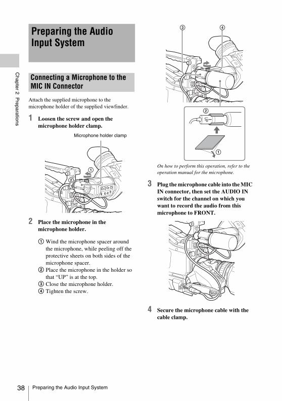
38
Chapter 2 P
reparations
Attach the supplied microphone to the microphone holder of the supplied viewfinder.
1 Loosen the screw and open the microphone holder clamp.
2 Place the microphone in the microphone holder.
1 Wind the microphone spacer around the microphone, while peeling off the protective sheets on both sides of the microphone spacer.
2 Place the microphone in the holder so that “UP” is at the top.
3 Close the microphone holder.4 Tighten the screw.
On how to perform this operation, refer to the operation manual for the microphone.
3 Plug the microphone cable into the MIC IN connector, then set the AUDIO IN switch for the channel on which you want to record the audio from this microphone to FRONT.
4 Secure the microphone cable with the cable clamp.
Preparing the Audio Input System
Connecting a Microphone to the MIC IN Connector
Microphone holder clamp
Preparing the Audio Input System
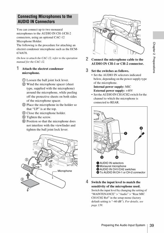
Chapter 2 P
reparations
You can connect up to two monaural microphones to the AUDIO IN CH-1/CH-2 connectors, using an optional CAC-12 Microphone Holder.The following is the procedure for attaching an electret condenser microphone such as the ECM-674/678.
On how to attach the CAC-12, refer to the operation manual for the CAC-12.
1 Attach the electret condenser microphone.
1 Loosen the ball joint lock lever.2 Wind the microphone spacer (sheet
type, supplied with the microphone) around the microphone, while peeling off the protective sheets on both sides of the microphone spacer.
3 Place the microphone in the holder so that “UP” is at the top.
4 Close the microphone holder.5 Tighten the screw.6 Position so that the microphone does
not interfere with the viewfinder and tighten the ball joint lock lever.
2 Connect the microphone cable to the AUDIO IN CH-1 or CH-2 connector.
3 Set the switches as follows.• Set the AUDIO IN selectors indicated
below, depending on the power supply type of the microphone.Internal power supply: MICExternal power supply: +48V
• Set the AUDIO IN CH1/CH2 switch for the channel to which the microphone is connected to REAR.
4 Switch the input level to match the sensitivity of the microphone used.Switch the input level by changing the setting of “MAINTENANCE” > “Audio” > “Rear MIC CH1/CH2 Ref” in the setup menu (factory default setting is “–60 dB”). For details, see page 139.
Connecting Microphones to the AUDIO IN Connectors
Microphone
1AUDIO IN selectors2Monaural microphone3AUDIO IN CH1/CH2 switches4To AUDIO IN CH-1 or CH-2 connector
Preparing the Audio Input System 39
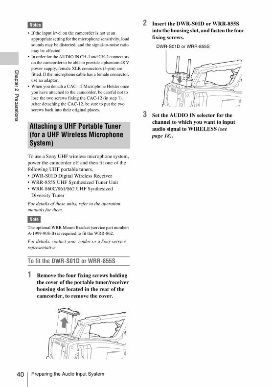
40
Chapter 2 P
reparations
Notes
• If the input level on the camcorder is not at an appropriate setting for the microphone sensitivity, loud sounds may be distorted, and the signal-to-noise ratio may be affected.
• In order for the AUDIO IN CH-1 and CH-2 connectors on the camcorder to be able to provide a phantom 48 V power supply, female XLR connectors (3-pin) are fitted. If the microphone cable has a female connector, use an adaptor.
• When you detach a CAC-12 Microphone Holder once you have attached to the camcorder, be careful not to lose the two screws fixing the CAC-12 (in step 1). After detaching the CAC-12, be sure to put the two screws back into their original places.
To use a Sony UHF wireless microphone system, power the camcorder off and then fit one of the following UHF portable tuners.• DWR-S01D Digital Wireless Receiver• WRR-855S UHF Synthesized Tuner Unit• WRR-860C/861/862 UHF Synthesized
Diversity Tuner
For details of these units, refer to the operation manuals for them.
Note
The optional WRR Mount Bracket (service part number: A-1999-908-B) is required to fit the WRR-862.
For details, contact your vendor or a Sony service representative
To fit the DWR-S01D or WRR-855S
1 Remove the four fixing screws holding the cover of the portable tuner/receiver housing slot located in the rear of the camcorder, to remove the cover.
2 Insert the DWR-S01D or WRR-855S into the housing slot, and fasten the four fixing screws.
3 Set the AUDIO IN selector for the channel to which you want to input audio signal to WIRELESS (see page 18).
Attaching a UHF Portable Tuner (for a UHF Wireless Microphone System)
DWR-S01D or WRR-855S
Preparing the Audio Input System
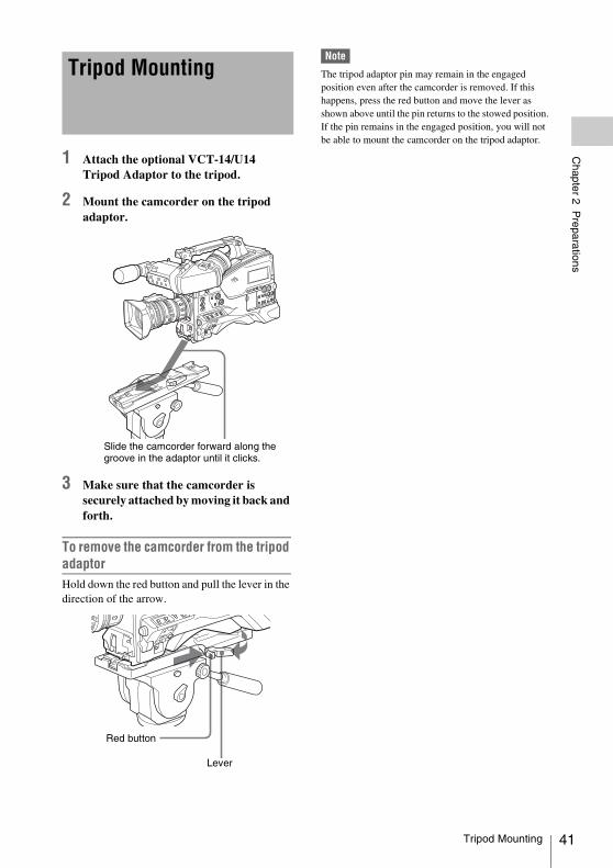
Chapter 2 P
reparations
1 Attach the optional VCT-14/U14 Tripod Adaptor to the tripod.
2 Mount the camcorder on the tripod adaptor.
3 Make sure that the camcorder is securely attached by moving it back and forth.
To remove the camcorder from the tripod adaptorHold down the red button and pull the lever in the direction of the arrow.
Note
The tripod adaptor pin may remain in the engaged position even after the camcorder is removed. If this happens, press the red button and move the lever as shown above until the pin returns to the stowed position. If the pin remains in the engaged position, you will not be able to mount the camcorder on the tripod adaptor.
Tripod Mounting
Slide the camcorder forward along the groove in the adaptor until it clicks.
Red button
Lever
Tripod Mounting 41
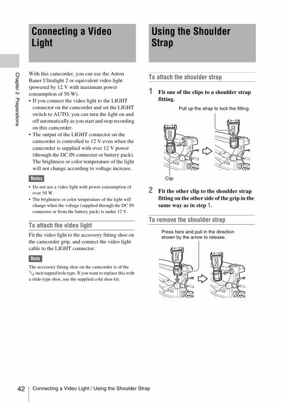
42
Chapter 2 P
reparations
With this camcorder, you can use the Anton Bauer Ultralight 2 or equivalent video light (powered by 12 V with maximum power consumption of 50 W).• If you connect the video light to the LIGHT
connector on the camcorder and set the LIGHT switch to AUTO, you can turn the light on and off automatically as you start and stop recording on this camcorder.
• The output of the LIGHT connector on the camcorder is controlled to 12 V even when the camcorder is supplied with over 12 V power (through the DC IN connector or battery pack). The brightness or color temperature of the light will not change according to voltage increase.
Notes
• Do not use a video light with power consumption of over 50 W.
• The brightness or color temperature of the light will change when the voltage (supplied through the DC IN connector or from the battery pack) is under 12 V.
To attach the video lightFit the video light to the accessory fitting shoe on the camcorder grip, and connect the video light cable to the LIGHT connector.
Note
The accessory fitting shoe on the camcorder is of the 1/4-inch tapped hole type. If you want to replace this with a slide-type shoe, use the supplied cold shoe kit.
To attach the shoulder strap
1 Fit one of the clips to a shoulder strap fitting.
2 Fit the other clip to the shoulder strap fitting on the other side of the grip in the same way as in step 1.
To remove the shoulder strap
Connecting a Video Light
Using the Shoulder Strap
Clip
Pull up the strap to lock the fitting.
Press here and pull in the direction shown by the arrow to release.
Connecting a Video Light / Using the Shoulder Strap
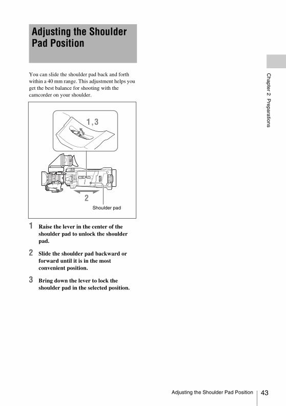
Chapter 2 P
reparations
You can slide the shoulder pad back and forth within a 40 mm range. This adjustment helps you get the best balance for shooting with the camcorder on your shoulder.
1 Raise the lever in the center of the shoulder pad to unlock the shoulder pad.
2 Slide the shoulder pad backward or forward until it is in the most convenient position.
3 Bring down the lever to lock the shoulder pad in the selected position.
Adjusting the Shoulder Pad Position
Shoulder pad
Adjusting the Shoulder Pad Position 43
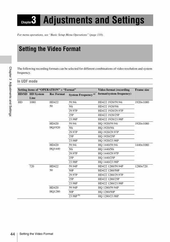
44
Chapter 3 A
djustments and S
ettings
For menu operations, see “Basic Setup Menu Operations” (page 110).
The following recording formats can be selected for different combinations of video resolution and system frequency.
In UDF mode
Chapter3 Adjustments and Settings
Setting the Video Format
Setting items of “OPERATION” > “Format” Video format (recording format/system frequency)
Frame sizeHD/SD HD System
LineRec Format System Frequency a)
HD 1080 HD42250
59.94i HD422 1920/59.94i 1920×1080
50i HD422 1920/50i
29.97P HD422 1920/29.97P
25P HD422 1920/25P
23.98P HD422 1920/23.98P
HD420HQ1920
59.94i HQ 1920/59.94i 1920×1080
50i HQ 1920/50i
29.97P HQ 1920/29.97P
25P HQ 1920/25P
23.98P HQ 1920/23.98P
HD420HQ1440
59.94i HQ 1440/59.94i 1440×1080
50i HQ 1440/50i
29.97P HQ 1440/29.97P
25P HQ 1440/25P
23.98P HQ 1440/23.98P
720 HD42250
59.94P HD422 1280/59.94P 1280×720
50P HD422 1280/50P
29.97P HD422 1280/29.97P
25P HD422 1280/25P
23.98P HD422 1280/23.98P
HD420HQ1280
59.94P HQ 1280/59.94P
50P HQ 1280/50P
23.98P b) HQ 1280/23.98P
Setting the Video Format
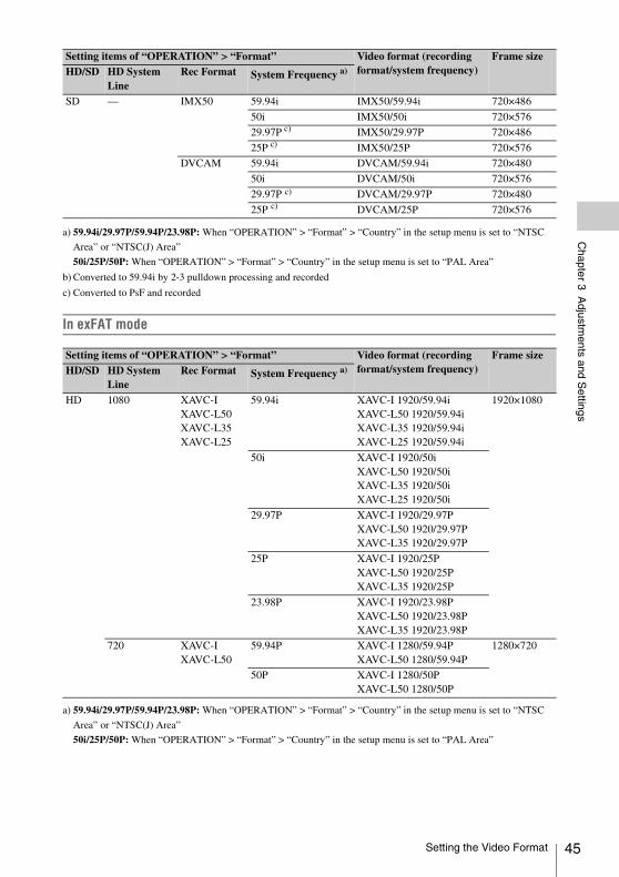
Chapter 3 A
djustments and S
ettings
a) 59.94i/29.97P/59.94P/23.98P: When “OPERATION” > “Format” > “Country” in the setup menu is set to “NTSC
Area” or “NTSC(J) Area”
50i/25P/50P: When “OPERATION” > “Format” > “Country” in the setup menu is set to “PAL Area”
b) Converted to 59.94i by 2-3 pulldown processing and recorded
c) Converted to PsF and recorded
In exFAT mode
a) 59.94i/29.97P/59.94P/23.98P: When “OPERATION” > “Format” > “Country” in the setup menu is set to “NTSC
Area” or “NTSC(J) Area”
50i/25P/50P: When “OPERATION” > “Format” > “Country” in the setup menu is set to “PAL Area”
SD — IMX50 59.94i IMX50/59.94i 720×486
50i IMX50/50i 720×576
29.97P c) IMX50/29.97P 720×486
25P c) IMX50/25P 720×576
DVCAM 59.94i DVCAM/59.94i 720×480
50i DVCAM/50i 720×576
29.97P c) DVCAM/29.97P 720×480
25P c) DVCAM/25P 720×576
Setting items of “OPERATION” > “Format” Video format (recording format/system frequency)
Frame sizeHD/SD HD System
LineRec Format System Frequency a)
HD 1080 XAVC-IXAVC-L50XAVC-L35XAVC-L25
59.94i XAVC-I 1920/59.94iXAVC-L50 1920/59.94iXAVC-L35 1920/59.94iXAVC-L25 1920/59.94i
1920×1080
50i XAVC-I 1920/50iXAVC-L50 1920/50iXAVC-L35 1920/50iXAVC-L25 1920/50i
29.97P XAVC-I 1920/29.97PXAVC-L50 1920/29.97PXAVC-L35 1920/29.97P
25P XAVC-I 1920/25PXAVC-L50 1920/25PXAVC-L35 1920/25P
23.98P XAVC-I 1920/23.98PXAVC-L50 1920/23.98PXAVC-L35 1920/23.98P
720 XAVC-IXAVC-L50
59.94P XAVC-I 1280/59.94PXAVC-L50 1280/59.94P
1280×720
50P XAVC-I 1280/50PXAVC-L50 1280/50P
Setting items of “OPERATION” > “Format” Video format (recording format/system frequency)
Frame sizeHD/SD HD System
LineRec Format System Frequency a)
Setting the Video Format 45
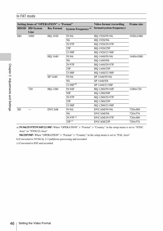
46
Chapter 3 A
djustments and S
ettings
In FAT mode
a) 59.94i/29.97P/59.94P/23.98P: When “OPERATION” > “Format” > “Country” in the setup menu is set to “NTSC
Area” or “NTSC(J) Area”
50i/25P/50P: When “OPERATION” > “Format” > “Country” in the setup menu is set to “PAL Area”
b) Converted to 59.94i by 2-3 pulldown processing and recorded
c) Converted to PsF and recorded
Setting items of “OPERATION” > “Format” Video format (recording format/system frequency)
Frame sizeHD/SD HD System
LineRec Format System Frequency a)
HD 1080 HQ 1920 59.94i HQ 1920/59.94i 1920×1080
50i HQ 1920/50i
29.97P HQ 1920/29.97P
25P HQ 1920/25P
23.98P HQ 1920/23.98P
HQ 1440 59.94i HQ 1440/59.94i 1440×1080
50i HQ 1440/50i
29.97P HQ 1440/29.97P
25P HQ 1440/25P
23.98P HQ 1440/23.98P
SP 1440 59.94i SP 1440/59.94i
50i SP 1440/50i
23.98P b) SP 1440/23.98P
720 HQ 1280 59.94P HQ 1280/59.94P 1280×720
50P HQ 1280/50P
29.97P HQ 1280/29.97P
25P HQ 1280/25P
23.98P HQ 1280/23.98P
SD — DVCAM 59.94i DVCAM/59.94i 720×480
50i DVCAM/50i 720×576
29.97P c) DVCAM/29.97P 720×480
25P c) DVCAM/25P 720×576
Setting the Video Format
Chapter 3 A
djustments and S
ettings
Select the recording mode between UDF, exFAT, and FAT.
1 Select “OPERATION” > “Format” > “File System” in the setup menu (see page 113).
2 Turn the MENU knob to select “UDF,” “exFAT,” or “FAT,” and press the knob.A confirmation message appears.
3 Select “Execute” to execute, or select “Cancel” to cancel, and then press the MENU knob.
4 Power the camcorder off and on again.
1 Select “OPERATION” > “Format” in the setup menu (see page 113).
2 Turn the MENU knob to select the item to change, and press the knob.
3 Turn the MENU knob to change the setting, and press the knob.A confirmation message appears.
4 Select “Execute” to execute, or select “Cancel” to cancel, and then press the MENU knob.
5 When the setting of HD/SD or Country was changed, power the camcorder off and on again.
Black balance and white balance adjustment values that are automatically set by the camcorder and the various settings are stored in the camcorder memory and retained even when the power is turned off.
Black balance adjustmentThe black balance will require adjustment in the following cases.• When the camcorder is used for the first time• When the camcorder has not been used for a
long time• When the camcorder is used under conditions in
which the surrounding temperature has changed greatly
• When the GAIN selector (L/M/H/Turbo) values have been changed with “OPERATION” > “Gain Switch” in the setup menu.
White balance adjustmentAlways readjust the white balance when the lighting conditions change.
In automatic black balance mode, adjustments are performed in the following order: black set and black balance. Manual black balance adjustment can be selected from the setup menu.
Note
Automatic black balance adjustment is disabled in the following case.• During recording• In a special recording modes (Picture Cache Rec,
Interval Rec, Frame Rec, Slow & Quick)• When the shutter mode is SLS
1 Set the OUTPUT/DCC switch to CAM.
Selecting the Recording Mode
Changing the Video Format
Adjusting the Black Balance and the White Balance
Adjusting the Black Balance
Adjusting the Black Balance and the White Balance 47
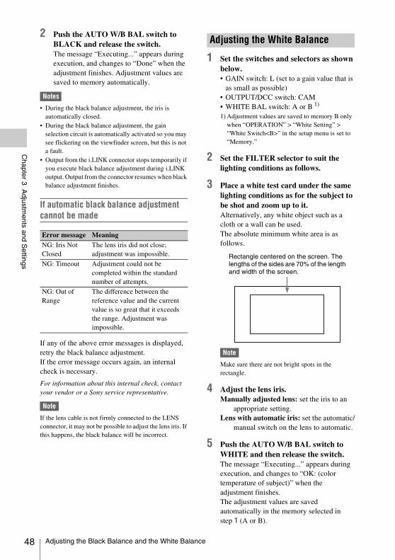
48
Chapter 3 A
djustments and S
ettings
2 Push the AUTO W/B BAL switch to BLACK and release the switch.The message “Executing...” appears during execution, and changes to “Done” when the adjustment finishes. Adjustment values are saved to memory automatically.
Notes
• During the black balance adjustment, the iris is automatically closed.
• During the black balance adjustment, the gain selection circuit is automatically activated so you may see flickering on the viewfinder screen, but this is not a fault.
• Output from the i.LINK connector stops temporarily if you execute black balance adjustment during i.LINK output. Output from the connector resumes when black balance adjustment finishes.
If automatic black balance adjustment cannot be made
If any of the above error messages is displayed, retry the black balance adjustment. If the error message occurs again, an internal check is necessary.
For information about this internal check, contact your vendor or a Sony service representative.
Note
If the lens cable is not firmly connected to the LENS connector, it may not be possible to adjust the lens iris. If this happens, the black balance will be incorrect.
1 Set the switches and selectors as shown below.• GAIN switch: L (set to a gain value that is
as small as possible) • OUTPUT/DCC switch: CAM• WHITE BAL switch: A or B 1)
1) Adjustment values are saved to memory B only when “OPERATION” > “White Setting” > “White Switch<B>” in the setup menu is set to “Memory.”
2 Set the FILTER selector to suit the lighting conditions as follows.
3 Place a white test card under the same lighting conditions as for the subject to be shot and zoom up to it. Alternatively, any white object such as a cloth or a wall can be used.The absolute minimum white area is as follows.
Note
Make sure there are not bright spots in the rectangle.
4 Adjust the lens iris.Manually adjusted lens: set the iris to an
appropriate setting.Lens with automatic iris: set the automatic/
manual switch on the lens to automatic.
5 Push the AUTO W/B BAL switch to WHITE and then release the switch.The message “Executing...” appears during execution, and changes to “OK: (color temperature of subject)” when the adjustment finishes.The adjustment values are saved automatically in the memory selected in step 1 (A or B).
Error message MeaningNG: Iris Not Closed
The lens iris did not close; adjustment was impossible.
NG: Timeout Adjustment could not be completed within the standard number of attempts.
NG: Out of Range
The difference between the reference value and the current value is so great that it exceeds the range. Adjustment was impossible.
Adjusting the White Balance
Rectangle centered on the screen. The lengths of the sides are 70% of the length and width of the screen.
Adjusting the Black Balance and the White Balance
Chapter 3 A
djustments and S
ettings
Note
If the camcorder has a zoom lens with an automatic iris, the iris may hunt 1) during the adjustment. To prevent this, adjust the iris gain knob (indicated as IG, IS, or S) on the lens.
For details, refer to the lens operation manual.
1) Hunting: Repeated brightening and darkening of the image, resulting from repeated response to automatic iris control.
If the automatic white balance adjustment cannot be made
If any of the above error messages is displayed, retry the white balance adjustment. If the error message occurs again, an internal check is necessary.
For information about this internal check, contact your vendor or a Sony service representative.
If you have no time to adjust the white balanceSet the WHITE BAL switch to PRST.This makes it possible to automatically set the white balance to 5600K (factory default value) by pressing the COLOR TEMP. button.The color temperature to which the white balance is set when the COLOR TEMP. button is pressed can be selected from among 3200K, 4300K, 5600K, and 6300K on OPERATION >Assignable SW in the setup menu. You can also assign color temperatures to the ASSIGN. 1/3 switches or ASSIGNABLE 4/5 switches.
To change the color temperature when the ND filter is switchedYou can assign electrical CC (color correction) filters to ND filters (see page 13). This allows you to change the color temperature automatically when the ND filter is switched.
1 Set “MAINTENANCE” > “White Filter” > “ND Filter C.Temp” in the setup menu (see page 146) to “On.”
2 To assign an electrical CC filter to FILTER selector position number 1, select “ND FLT C.Temp<1>.” To assign it to positions 2 to 4, select “ND FLT C.Temp<2-4>.”
3 Turn the MENU knob to select the desired color temperature.As you turn the MENU knob, the color temperature changes as follows: 3200K y 4300K y 5600K y 6300K.
4 Repeat steps 2 and 3 as required.
To switch between electrical CC filters with an assignable switchYou can assign the function that switches between electrical CC filters to an assignable switch. This allows you to switch between color temperatures (3200K/4300K/5600K/6300K) that have been assigned to up to four positions (A to D) with each press of the assignable switch.Regardless of assignments to assignable switches, you can also switch between the color temperatures assigned to each position from a RM-B170/B750 Remote Control Unit.
1 Select “MAINTENANCE” > “White Filter” in the setup menu (see page 146).
2 Select the position to which to assign a CC filter by selecting one of “Electrical CC<A>” to “Electrical CC <D>,” and then turn the MENU knob to select the desired color temperature.As you turn the MENU knob, the color temperature changes as follows: 3200K y 4300K y 5600K y 6300K.
Error message MeaningNG: Low Light The white video level is too low.
Either open the lens iris or increase the gain.
NG: Timeout Adjustment could not be completed within the standard number of attempts.
NG: High Light The white video level is too high. Either stop down the lens iris or change the ND filter.
Adjusting the Black Balance and the White Balance 49

50
Chapter 3 A
djustments and S
ettings
To set no color temperatureSelect “-----” with “Electrical CC<C>” or “Electrical CC<D>” selected.When the assignable switch is pressed, the setting for that position is not displayed. For example, if “-----” is set for one position, then switching between the remaining three positions is carried out.
3 Repeat step 2 as required.
4 Assign the electrical CC filter switching function (ELECTRICAL CC) to an assignable switch (see page 161).
White balance memoryValues stored in memory are held until the white balance is next adjusted even when the camcorder power is turned off.The camcorder has two white balance memories, A and B. You can automatically save adjustment values for each ND filter in the memory that corresponds to the WHITE BAL switch setting (A or B). The camcorder has four built-in ND filters, allowing you to save a total of eight adjustment values (4 × 2). However, the contents of the memories are not linked to ND filter settings in the following cases.• When the number of memories allocated to
each of A and B is limited to one by setting “OPERATION” > “White Setting” > “Filter White Memory” in the setup menu to “Off.”
• When the electrical CC filter switching function has been assigned to an assignable switch, or when a remote control unit has been connected. (In these cases, the contents of white balance memory are linked to electrical CC filter positions (A to D).)
Also, when “OPERATION” > “White Setting” > “White Switch<B>” in the setup menu is set to “ATW (Auto Tracing White Balance),” and the WHITE BAL switch is set to B, the ATW function is activated to automatically adjust the white balance of the picture being shot for varying lighting conditions.
Note
While the ATW function is activated, the color temperature of the subject may differ from the color temperature that is displayed on the viewfinder screen.
Standard modeSelect this mode for shooting fast-moving subjects with little blurring.You can set the shutter speed in one of two shutter modes: Speed mode, in which the speed is set in seconds, and Angle mode, in which the speed is set in degrees.
Speed mode
a) This speed cannot be selected when the camcorder is in Slow & Quick Motion mode and “OPERATION” > “Rec Function” > “Frame Rate” in the setup menu is set to a value that is greater than the system frequency.
Angle mode180°, 90°, 45°, 22.5°, and 11.25°
ECS (Extended Clear Scan) modeSelect this mode for obtaining images with no horizontal bands of noise when shooting subjects such as monitor screens.As shown in the following tables, the range of shutter speeds that can be set varies depending on whether the Slow & Quick Motion (S&Q) function is on or off.
Setting the Electronic Shutter
Shutter Modes
System frequency
Shutter speed (unit: seconds)
59.94i59.94P50i50P
1/60, 1/100,
1/120, 1/125, 1/250, 1/500, 1/1000, 1/2000
29.97P 1/40a), 1/50
a), 1/60, 1/100,
1/120, 1/125, 1/250, 1/500, 1/1000, 1/2000
25P 1/33 a), 1/50
a), 1/60, 1/100, 1/120,
1/125, 1/250, 1/500, 1/1000, 1/2000
23.98P 1/32 a), 1/48
a), 1/50a), 1/60, 1/96, 1/100,
1/120, 1/125, 1/250, 1/500, 1/1000, 1/2000
Setting the Electronic Shutter
Chapter 3 A
djustments and S
ettings
System lines: 1080
System lines: 720
SLS (slow speed shutter) modeSelect this mode for shooting subjects in low level lighting conditions.
Notes
• SLS mode cannot be used when the video format is SP 1440/23.98P or when the camcorder is in Slow & Quick Motion mode.
• It is not possible to output the color bar signal, turn the SLS mode on or off, or change the number of accumulated frames when the number of accumulated frames is set to 16, 32 or 64.
Notes
• When the automatic iris is used, the iris opens wider as the shutter speed increases, thus reducing the depth of field.
• The selectable shutter speeds vary depending on the current system frequency.
To switch between Speed mode and Angle mode
1 Select “OPEARTION” > “Shutter” > “Shutter Select” in the setup menu (see page 127).
2 Turn the MENU knob to select “Second” or “Degree,” and then press the knob.
To set the shutter mode and standard-mode shutter speedOnce the shutter speed is selected, it is retained even when the camcorder power is turned off.
1 Push the SHUTTER selector from ON to SELECT.The current shutter setting indication appears for about three seconds.
2 Before the shutter setting indication disappears, push the SHUTTER selector down to SELECT again and repeat this until the desired mode or speed appears.When all modes and speeds are displayed, the display changes in the following order.
Note
Depending on the frame rate setting (see page 117), some shutter speeds cannot be selected in Slow & Quick Motion mode. These speeds are replaced by the slowest selectable shutter speed.
Example: If you perform Slow & Quick Motion shooting when setting the frame rate to 60 and the video format to HQ1280/29.97PThe shutter speed is indicated as follows.
When Slow & Quick Motion mode is off1/40t1/50t1/60t1/100t...
When Slow & Quick Motion mode is on1/60t1/60t1/60t1/100t...
To set the shutter speed in ECS mode
1 Set the shutter mode to ECS (see the previous item).
2 Turn the MENU knob to select the desired frequency or number of frames.
To set the shutter speed in SLS mode
1 Set “OPERATION” > “Shutter” > “Slow Shutter” in the setup menu to “On” (see page 127).
System frequency
Shutter speed (unit: Hz)S&Q: Off S&Q: On
59.94i 60.00 to 3800 —
50i 50.00 to 3500 —
29.97P 29.99 to 4100 32.01 to 4100
23.98P 23.99 to 3700 32.02 to 3700
25P 25.00 to 3900 32.03 to 3900
System frequency
Shutter speed (unit: Hz)S&Q: Off S&Q: On
59.94P 60.07 to 4100 32.01 to 4100
50P 50.03 to 3900 32.03 to 3900
29.97P 29.99 to 4100 32.01 to 4100
23.98P 23.99 to 3700 32.02 to 3700
25P 25.00 to 3900 32.03 to 3900
Number of accumulated frames2, 3, 4, 5, 6, 7, 8, 16, 32, 64
Selecting the Shutter Mode and Shutter Speed
Setting the Electronic Shutter 51
52
Chapter 3 A
djustments and S
ettings
2 Select the desired number of accumulated frames with “OPERATION” > “Shutter” > “SLS Frames” in the setup menu.
The reference value for automatic iris adjustment can be changed to aid the shooting of clear pictures of back-lit subjects, or to prevent blown-out highlights. The reference value for the lens iris can be set within the following range with respect to the standard value.• 0.25 to 1 (increasing by increments of 0.25):
About 0.25 to 1 stop further open• –0.25 to –1 (decreasing by increments of 0.25):
About 0.25 to 1 stop further closeAlso you can set the area where light detection occurs.
To change the reference value
1 Set “OPERATION” > “Auto Iris” > “Iris Override” in the setup menu to “On” (see page 124).
2 Set the MENU ON/OFF switch to OFF.
3 Turn the MENU knob to change the reference value.
Note
Be sure to confirm that the current shutter mode is not ECS.
An indicator of the current reference value is shown at the iris position indication (see page 28) on the viewfinder screen.
To make the iris more openTurn the MENU knob counterclockwise as seen from the front of the camcorder.Select one of 0.25, 0.5, 0.75, or 1.
To stop down the irisTurn the MENU knob clockwise as seen from the front of the camcorder.Select one of –0.25, –0.5, –0.75, or –1.
The changed reference value is retained until the power of the camcorder is turned off.Even if the reference value is changed, it reverts to the standard value every time the power is turned on.
Changing the Reference Value for Automatic Iris Adjustment
Changing the Reference Value for Automatic Iris Adjustment
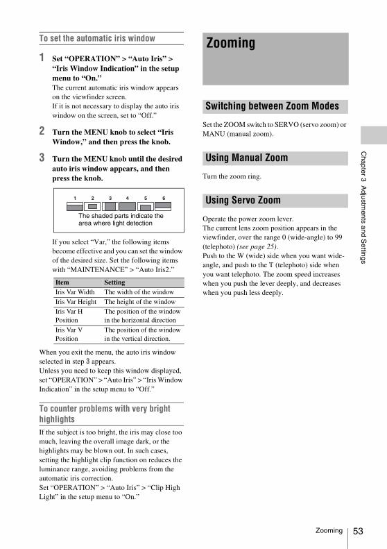
Chapter 3 A
djustments and S
ettings
To set the automatic iris window
1 Set “OPERATION” > “Auto Iris” > “Iris Window Indication” in the setup menu to “On.”The current automatic iris window appears on the viewfinder screen.If it is not necessary to display the auto iris window on the screen, set to “Off.”
2 Turn the MENU knob to select “Iris Window,” and then press the knob.
3 Turn the MENU knob until the desired auto iris window appears, and then press the knob.
If you select “Var,” the following items become effective and you can set the window of the desired size. Set the following items with “MAINTENANCE” > “Auto Iris2.”
When you exit the menu, the auto iris window selected in step 3 appears.Unless you need to keep this window displayed, set “OPERATION” > “Auto Iris” > “Iris Window Indication” in the setup menu to “Off.”
To counter problems with very bright highlightsIf the subject is too bright, the iris may close too much, leaving the overall image dark, or the highlights may be blown out. In such cases, setting the highlight clip function on reduces the luminance range, avoiding problems from the automatic iris correction.Set “OPERATION” > “Auto Iris” > “Clip High Light” in the setup menu to “On.”
Set the ZOOM switch to SERVO (servo zoom) or MANU (manual zoom).
Turn the zoom ring.
Operate the power zoom lever. The current lens zoom position appears in the viewfinder, over the range 0 (wide-angle) to 99 (telephoto) (see page 25).Push to the W (wide) side when you want wide-angle, and push to the T (telephoto) side when you want telephoto. The zoom speed increases when you push the lever deeply, and decreases when you push less deeply.
Item SettingIris Var Width The width of the window
Iris Var Height The height of the window
Iris Var H Position
The position of the window in the horizontal direction
Iris Var V Position
The position of the window in the vertical direction.
The shaded parts indicate the area where light detection
Zooming
Switching between Zoom Modes
Using Manual Zoom
Using Servo Zoom
Zooming 53
54
Chapter 3 A
djustments and S
ettings
Note
The lens is designed with an extra margin at the infinity position (∞ ), to compensate for focus drifting due to variations in temperature. When shooting a subject at infinity in MF or Full MF mode, check the picture in the viewfinder as you focus.
When you slide the focus ring back (toward the camcorder), the focus mode becomes Full MF mode, in which all focus adjustments are manual.
Note
When you slide the focus ring back, the focus instantly moves to the mark position.
Focus by turning the focus ring while viewing the viewfinder.The distance indications on the ring are valid in Full MF mode. The distances where the picture is in focus correspond to absolute positions of the focus ring.
PeakingYou can turn the PEAKING knob on the viewfinder to use the peaking function. Edges are emphasized in the monitor picture, which facilitates manual focusing.The recorded video signals are not affected.
When you slide the focus ring forward (toward the lens hood), and set the FOCUS switch to M (manual), the focus mode becomes MF mode, in which focus adjustments are manual but auto focus is available only when necessary.
Using the focus ringFocus by turning the focus ring while viewing the viewfinder.The distance indications on the ring are invalid in MF mode.
One-push auto focusPress the PUSH AF button. Auto focus is enabled temporarily.One-push auto focus ends when the subject is brought into focus.
MF assist function When the MF assist function is on (see page 160), auto focus starts when you stop adjusting with the focus ring, enabling fine adjustments with the subject at the center of the screen.Auto focusing by the MF assist function ends when the fine adjustments end.
When you slide the focus ring forward, and set the FOCUS switch to A (auto), the focus mode becomes AF mode, in which auto focus is always active.The distance indications on the ring are invalid in AF mode.
When the focus mode is MF or AF, you can set the MACRO switch to the ON side to enable macro mode. Macro mode allows you to focus over the range that includes the macro area.Macro mode is disabled in Full MF mode.
Adjusting the Focus
Adjusting in Full MF Mode
Adjusting in MF Mode
Adjusting in AF Mode
Using Macro Mode
Adjusting the Focus
Chapter 3 A
djustments and S
ettings
When you set the AUDIO SELECT switch to AUTO, the input levels of analog audio signals recorded on each channel are adjusted automatically. You can also make manual adjustments.
Note
Even if you set the AUDIO SELECT switch to AUTO, the input levels of digital audio signals are not adjusted automatically.
Target audio level for manual audio level adjustmentMake adjustment using –20 dB as the target level.If the audio level meter shows a maximum level of 0 dB, then it indicates that the input audio level is excessive.
1 To adjust the signal input to the AUDIO IN CH-1 or CH-2 connector, set the AUDIO IN CH-1 or CH-2 switch to REAR.To adjust both input signals, set both switches to REAR.
2 Set the AUDIO SELECT switch(es) corresponding to the channel(s) selected in step 1 to MANUAL.
3 With the LEVEL control(s) for the channel(s) selected in step 1, adjust so that the audio level meter shows up to –20 dB for a normal input volume.
Correspondence between recording level adjustments and audio level controlsYou can select which audio level control controls the audio recording level of the input to each of the AUDIO IN CH-1/CH-2 connectors on
“MAINTENANCE” > “Audio” in the setup menu,
Rear1/WRR Level: Channel 1 recording level (see page 141)
Rear2/WRR Level: Channel 2 recording level (see page 141)
Note
When you have operation of the LEVEL (CH1/CH2) knobs and MIC LEVEL control linked together, if the MIC LEVEL control is set to 0, the audio signals on channels 1 and 2 cannot be recorded. Check the position of the MIC LEVEL control before adjusting the LEVEL (CH1/CH2) knobs.
1 Set either or both of the AUDIO IN switch(es) to FRONT.
2 Set the AUDIO SELECT switch(es) for the desired channel(s) selected in step 1 to MANUAL.
3 Turn the MIC LEVEL control, and adjust so that the audio level meter shows up to –20 dB for a normal input volume.
Correspondence between recording level adjustments and audio level controlsYou can select which audio level control controls the audio recording level of the front microphone input on “MAINTENANCE” > “Audio” in the setup menu.
MIC CH1 Level: Channel 1 recording level (see page 140)
MIC CH2 Level: Channel 2 recording level (see page 140)
Note
When you have operation of the MIC LEVEL control and LEVEL (CH1/CH2) knobs linked together, if the LEVEL (CH1/CH2) controls are set to 0, the audio signals on channels 1 and 2 cannot be recorded. Check the position of the LEVEL (CH1/CH2) knobs before adjusting the MIC LEVEL control.
Adjusting the Audio Level
Manually Adjusting the Audio Levels of the Audio Inputs from the AUDIO IN CH-1/CH-2 Connectors
Manually Adjusting the Audio Level of the MIC IN Connector
Adjusting the Audio Level 55
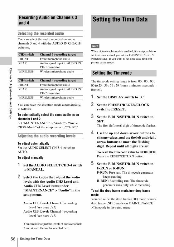
56
Chapter 3 A
djustments and S
ettings
Selecting the recorded audioYou can select the audio recorded on audio channels 3 and 4 with the AUDIO IN CH3/CH4 switches.
You can have the selection made automatically, as follows.
To automatically select the same audio as on channels 1 and 2Set “MAINTENANCE” > “Audio” > “Audio CH3/4 Mode” of the setup menu to “Ch 1/2.”
Adjusting the audio recording levels
To adjust automaticallySet the AUDIO SELECT CH 3-4 switch to AUTO.
To adjust manually
1 Set the AUDIO SELECT CH 3-4 switch to MANUAL.
2 Select the knobs that adjust the audio levels with the Audio CH3 Level and Audio CH4 Level items under “MAINTENANCE” > “Audio” in the setup menu.
Audio CH3 Level: Channel 3 recording level (see page 141)
Audio CH4 Level: Channel 4 recording level (see page 141)
You can now adjust the levels of audio channels 3 and 4 with the knobs selected here.
Note
When picture cache mode is enabled, it is not possible to set time data, even if you set the F-RUN/SET/R-RUN switch to SET. If you want to set time data, first exit picture cache mode.
The timecode setting range is from 00 : 00 : 00 : 00 to 23 : 59 : 59 : 29 (hours : minutes : seconds : frames).
1 Set the DISPLAY switch to TC.
2 Set the PRESET/REGEN/CLOCK switch to PRESET.
3 Set the F-RUN/SET/R-RUN switch to SET.The first (leftmost) digit of timecode flashes.
4 Use the up and down arrow buttons to change values, and use the left and right arrow buttons to move the flashing digit. Repeat until all digits are set.
To reset the timecode value to 00:00:00:00Press the RESET/RETURN button.
5 Set the F-RUN/SET/R-RUN switch to F-RUN or R-RUN.F-RUN: Free run. The timecode generator
keeps running.R-RUN: Recording run. The timecode
generator runs only while recording.
To set the drop frame mode/non-drop frame modeYou can select the drop frame (DF) mode or non-drop frame (NDF) mode on MAINTENANCE >Timecode in the setup menu.
Recording Audio on Channels 3 and 4
CH3 switch Channel 3 recording targetFRONT Front microphone audio
REAR Audio signal input to AUDIO IN CH-1 connector
WIRELESS Wireless microphone audio
CH4 switch Channel 4 recording targetFRONT Front microphone audio
REAR Audio signal input to AUDIO IN CH-2 connector
WIRELESS Wireless microphone audio
Setting the Time Data
Setting the Timecode
Setting the Time Data
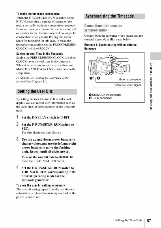
Chapter 3 A
djustments and S
ettings
To make the timecode consecutiveWhen the F-RUN/SET/R-RUN switch is set to R-RUN, recording a number of scenes on the media normally produces consecutive timecode. However, once you remove the media and record on another media, the timecode will no longer be consecutive when you use the original media again for recording. In this case, to make the timecode consecutive, set the PRESET/REGEN/CLOCK switch to REGEN.
Saving the real Time in the TimecodeSetting the PRESET/REGEN/CLOCK switch to CLOCK saves the real time in the timecode.When it is necessary to set the actual time, use MAINTENANCE >Clock Set >Date/Time in the setup menu.
For details, see “Setting the Date/Time of the Internal Clock” (page 35).
By setting the user bits (up to 8 hexadecimal digits), you can record user information such as the date, time, or scene number on the timecode track.
1 Set the DISPLAY switch to U-BIT.
2 Set the F-RUN/SET/R-RUN switch to SET.The first (leftmost) digit flashes.
3 Use the up and down arrow buttons to change values, and use the left and right arrow buttons to move the flashing digit. Repeat until all digits are set.
To reset the user bit data to 00 00 00 00Press the RESET/RETURN button.
4 Set the F-RUN/SET/R-RUN switch to F-RUN or R-RUN, corresponding to the desired operating mode for the timecode generator.
To store the user bit setting in memoryThe user bit setting (apart from the real time) is automatically retained in memory even when the power is turned off.
Connections for timecode synchronizationConnect both the reference video signal and the external timecode as illustrated below.
Example 1: Synchronizing with an external timecode
Setting the User Bits
Synchronizing the Timecode
External timecode
1GENLOCK IN connector2TC IN connector
Reference video signal
Setting the Time Data 57
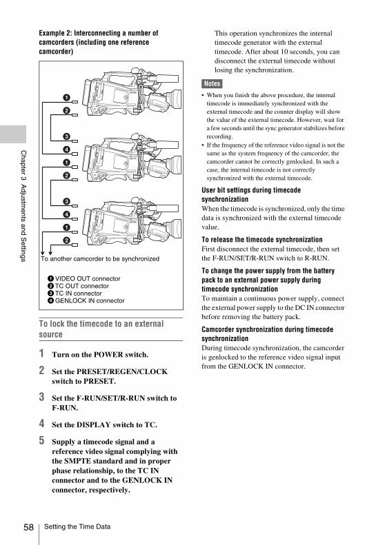
58
Chapter 3 A
djustments and S
ettings
Example 2: Interconnecting a number of camcorders (including one reference camcorder)
To lock the timecode to an external source
1 Turn on the POWER switch.
2 Set the PRESET/REGEN/CLOCK switch to PRESET.
3 Set the F-RUN/SET/R-RUN switch to F-RUN.
4 Set the DISPLAY switch to TC.
5 Supply a timecode signal and a reference video signal complying with the SMPTE standard and in proper phase relationship, to the TC IN connector and to the GENLOCK IN connector, respectively.
This operation synchronizes the internal timecode generator with the external timecode. After about 10 seconds, you can disconnect the external timecode without losing the synchronization.
Notes
• When you finish the above procedure, the internal timecode is immediately synchronized with the external timecode and the counter display will show the value of the external timecode. However, wait for a few seconds until the sync generator stabilizes before recording.
• If the frequency of the reference video signal is not the same as the system frequency of the camcorder, the camcorder cannot be correctly genlocked. In such a case, the internal timecode is not correctly synchronized with the external timecode.
User bit settings during timecode synchronizationWhen the timecode is synchronized, only the time data is synchronized with the external timecode value.
To release the timecode synchronizationFirst disconnect the external timecode, then set the F-RUN/SET/R-RUN switch to R-RUN.
To change the power supply from the battery pack to an external power supply during timecode synchronizationTo maintain a continuous power supply, connect the external power supply to the DC IN connector before removing the battery pack.
Camcorder synchronization during timecode synchronizationDuring timecode synchronization, the camcorder is genlocked to the reference video signal input from the GENLOCK IN connector.
1VIDEO OUT connector2TC OUT connector3TC IN connector4GENLOCK IN connector
To another camcorder to be synchronized
Setting the Time Data
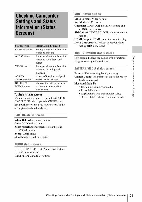
Chapter 3 A
djustments and S
ettings
To display status screensWith no menu is displayed, push the STATUS ON/SEL/OFF switch up to the ON/SEL side. Each push selects the next status screen, in the order given in the table above.CAMERA status screenWhite Bal: White balance status Gain: GAIN switch status Zoom Speed: Zoom speed set with the lens
ZOOM buttonZebra: Zebra status Skin Detail: Skin details status
AUDIO status screenCH-1/CH-2/CH-3/CH-4: Audio level meters
and input sources Wind Filter: Wind filter settings
VIDEO status screenVideo Format: Video formatRec Mode: REC Format Output&i.LINK: Output&i.LINK setting and
i.LINK usage statusSDI Output: HD/SD SDI OUT connector output
setting HDMI Output: HDMI connector output settingDown Converter: SD output down converter
setting (HD mode only)
ASSIGN SWITCH status screenThis screen displays the names of the functions assigned to assignable switches
BATTERY/MEDIA status screenBattery: The remaining battery capacity Charge Count: The number of times the battery
has been charged Media A/Media B:
• Remaining capacity of media• Recordable time• Approximate writable lifetime (Life)
“Life 100%” is shown for unused media.
Checking Camcorder Settings and Status Information (Status Screens)
Status screen Information displayedCAMERA status Settings and status information
related to shooting
AUDIO status Settings and status information related to audio input and output
VIDEO status Settings and status information related to recording and playback
ASSIGN SWITCH status
Names of functions assigned to assignable switches
BATTERY/MEDIA status
Status of the battery mounted on the camcorder and the media status
Checking Camcorder Settings and Status Information (Status Screens) 59
60
Chapter 4 S
hooting
This camcorder records video and audio on SxS memory cards (not supplied) loaded into one or both of its memory card slots.You can use the camcorder with the following devices to make recording.• MEAD-SD02 Media Adaptor (when the
recording mode is FAT), or QDA-EX1 XQD ExpressCard Adapter (when the recording mode is UDF/exFAT/FAT)
SxS memory cards that can be used with this camcorderUse the following Sony SxS memory cards (SxS PRO or SxS-1) with this camcorder.
SxS PRO+ series
SxS PRO series
SxS-1 series
The memory cards listed above comply with the ExpressCard memory card standard.• SxS, SxS PRO and SxS-1 are trademarks of
Sony Corporation.• The ExpressCard label and logo are property of
the Personal Computer Memory Card International Association (PCMCIA) and are licensed to Sony Corporation. Other trademarks and trade names are the property of their respective owners.
To load SxS memory cards
1 Slide the cover to the left to open.
2 Insert an SxS memory card into a card slot.
3 Close the cover.
ACCESS lamp status indicationsCard slots A and B each have an ACCESS lamp to indicate the slot status.
To eject SxS memory cards
1 Open the cover, and then press the EJECT button to release the lock and pull the button out.
2 Press the EJECT button again to eject the card.
Note
Data integrity cannot be guaranteed if you power the camcorder off or remove a memory card while the card is being accessed. Doing so may corrupt all data recorded on the card. Always make sure that the ACCESS lamp is lit green or not lit before you power the camcorder off or remove a memory card.
Chapter4 Shooting
Handling SxS Memory Cards
About SxS Memory Cards
Loading and Ejecting SxS Memory Cards
Lamp Slot statusLights in orange Accessing the SxS memory card
(lights during data reading and writing)
Lights in green Standby (the loaded SxS memory card is ready for recording or playback)
Not lit • No SxS memory card is loaded.• An unusable card is loaded.• An SxS memory card is loaded,
but the other slot is selected.
Handling SxS Memory Cards
Chapter 4 S
hooting
When SxS memory cards are loaded in both slot A and slot B, you can press the SLOT SELECT button to select the SxS memory card to use.The camcorder switches automatically to the other card if the selected card becomes full during recording.
Note
The SLOT SELECT button is disabled during playback. Even when pressed, it does not change the selected slot. Button operations are enabled when a thumbnail screen (see page 96) is displayed.
When you load an unformatted SxS memory card, or load an SxS memory card that has been formatted to other specifications, a message “Cannot Use Media(A)/Unsupported File System” appears in the viewfinder. In this case, format the memory card in the following way.
Note
SxS memory cards must be formatted on an XDCAM EX device. Cards in other formats cannot be used.
To format (initialize) a memory card
1 Select “OPERATION” > “Format Media” in the setup menu (see page 115).
2 Select “Media(A)” (slot A) or “Media(B)” (slot B).
3 Turn the MENU knob to select “Execute,” and then press the knob.The confirmation message for formatting is displayed on the viewfinder screen.
4 Turn the MENU knob to select “Execute,” and press the knob.
Execution of the format starts.During execution of the format, a progress indication appears (%), and the ACCESS lamp lights in orange.
Recording and playback during format executionEven during execution of a format, recording and playback are possible using an SxS memory card loaded into the other card slot.
If the format operation failsA format operation may fail because the SxS memory card is write protected, or because it is not the type of card specified for use with this camcorder.In this case, an error message appears. Following the instructions in the error message and exchange the card for an SxS memory card that can be used with this camcorder.
Notes
• All data is erased when you format a memory card, including setup files and all of the recorded video data.
• Use the format function of this camcorder to format SxS memory cards for use on this camcorder. The formats of cards formatted on other devices are not recognized as valid formats, making it necessary to format them again on this camcorder.
You can check the remaining capacity of the SxS memory cards loaded in the two slots by checking the recording media remaining capacity display in the viewfinder.
The camcorder calculates the remaining recording time for the media in each slot on the basis of the current video format (recording bit rate), and displays it in units of minutes.You can also check the remaining time in the BATTERY/MEDIA status screen (see page 59).
Note
The mark appears when a memory card is write protected.
When to exchange SxS memory cards• The warning message “Media Near Full”
appears, the WARNING indicator and the REC indication on the viewfinder screen flash, and the buzzer sounds when the total remaining recording time of the two memory cards falls to five minutes during recording.Exchange one of the cards for media with available recording capacity.
Selecting the SxS Memory Card to Use
Formatting (Initializing) SxS Memory Cards
Checking the Remaining Recording Time
Handling SxS Memory Cards 61
62
Chapter 4 S
hooting
• If you continue recording, the message “Media Full” appears and recording stops when the total remaining recording time falls to 0.
Note
About up to 600 clips can be recorded on one SxS memory card.The display of remaining recording time changes to “0” and the message “Media Full” appears when the clip limit is reached.
When you load an SxS memory card that needs to be restored, a message appears in the viewfinder to ask whether you want to restore it.
To restore a cardTurn the MENU knob to select “Execute,” and then press the knob.The restoration starts.During the restoration, a execution message appears, the progress is displayed (%), and the ACCESS lamp lights in orange.When the restoration finishes, a completion message is displayed for three seconds.
If restoration fails• Write protected SxS memory cards and cards on
which memory errors have occurred cannot be restored. A warning message appears for such cards. Follow the instructions in the message and unprotect the card or replace it with another card.
• SxS memory cards on which memory errors have occurred may become usable if they are reformatted.
• In some cases, some clips can be restored while others cannot. The restored clips can be played normally.
• If the message “Could not Restore Some Clips” keeps appearing after repeated attempts at restoration, it may be possible to restore the SxS memory card with the following procedure.
1 Use the camcorder’s copy function (see page 104) or the supplied application software (see page 171) to copy the required clips to another SxS memory card.
2 Format the unusable SxS memory card on the camcorder.
3 Copy the required clips back to the newly formatted SxS memory card.
Recording and playback during restorationEven while restoration is in progress, you can record and play an SxS memory card in the other card slot.
Note
For restoration of media recorded with this camcorder, be sure to use this camcorder. Media recorded with a device other than this camcorder or with another camcorder of different version (even of the same model) may not be restored using this camcorder.
Restoring SxS Memory Cards
Handling SxS Memory Cards
Chapter 4 S
hooting
Notes
• A media adaptor cannot obtain the high reliability and durability equivalent to an SxS memory card for professional use.
• Not all memory cards have been tested and are not guaranteed to work with this camcorder. For compatible memory cards, contact your Sony dealer.
By using an optional QDA-EX1 XQD ExpressCard Adapter, you can insert an XQD memory card into the SxS memory card slot and use it instead of an SxS memory card.
For details on using a QDA-EX1 XQD ExpressCard Adapter, refer to the instruction manual supplied with it.
Notes
• High-speed playback may not be properly achieved with an XQD memory card.
• Slow Motion recording by the Slow & Quick Motion recording function cannot be made with an XQD memory card.
FormattingWhen you use an XQD memory card with this camcorder, formatting is required.An XQD memory card to be used with this camcorder must be formatted using the format function of this camcorder.It is also necessary to format an XQD memory card for use if a caution message is displayed when you mount the XQD memory card.For an XQD memory card that was formatted with another system unsupported by this camcorder, the message “Unsupported File System” is displayed on the LCD monitor/viewfinder screen.Format the XQD memory card as instructed below.
To execute formattingSpecify the slot on “OPERATION” > “Format Media” in the setup menu, then select “Execute.”
On a confirmation message, select “Execute” again.
An in-progress message and status bar (%) are displayed, and the access lamp lights in orange.When formatting is completed, a completion message is displayed for three seconds.
Note
When formatting, all data in an XQD memory card-including protected images-are erased and cannot be restored.
Connection between the camcorder and a computerTo use an XQD memory card in which data have been recorded with an XDCAM EX-series product, insert it into the slot of the camcorder and connect between the computer and this camcorder using a USB cable.
To use media formatted with this camcorder in the slots of other devicesMake a backup of the media, then format it using the other device.
When FAT mode is selected, use of the optional MEAD-SD02 Media Adaptor permits you to insert an SDHC card to the SxS memory card slot of the camcorder and use it for recording and playback in the same way as with an SxS memory card.
Usable SDHC cardClass 10 SDHC card
For details on use of the MEAD-SD02 Media Adaptor, refer to the Operating Instructions of the adaptor.
Notes
• In UDF/exFAT mode, no Media Adaptor can be used.• High-speed playback may not be properly achieved
with an SDHC card.• When using the Slow & Quick Motion function with
an SDHC card, you cannot perform slow motion shooting.
Using a Media Adaptor
XQD Memory Cards
SDHC Cards (FAT Mode only)
Using a Media Adaptor 63
64
Chapter 4 S
hooting
FormattingWhen you use an SDHC card with this camcorder, formatting is required.An SDHC card to be used with this camcorder must be formatted using the format function of this camcorder.It is also necessary to format an SDHC card for use if a caution message is displayed when you mount the SDHC card.For an SDHC card that was formatted with another system unsupported by this camcorder, the message “Unsupported File System” is displayed on the LCD monitor/EVF screen.Format the SDHC card as instructed below.
To execute formattingSelect “Media(A)” (slot A) or “Media(B)” (slot B) on “OPERATION” > “Format Media” in the setup menu, and select “Execute.”An in-progress message and status bar (%) are displayed, and the ACCESS lamp lights in orange. When formatting is completed, a completion message is displayed for three seconds.
Note
In formatting, all data in an SDHC card, including protected images, are erased and cannot be restored.
Connection between the camcorder and a computerTo use an SDHC card in which data have been recorded with an XDCAM EX-series product, establish USB connection between the computer and this camcorder and insert it into the slot of the camcorder, or use a specified USB card reader SBAC-US20.
To use a media formatted with this camcorder in the slots of other devicesMake a backup of the media, then format it using the other device.
In UDF/exFAT mode, you can connect a USB flash drive connected to the external device to record, save and load the following data.• Planning metadata (see page 93)• Setting data (see page 163)
Notes
• Use USB flash drives with capacity of 4 GB or greater.• USB flash drives other than the recommended flash
drives listed above may not be recognized when connected to the USB connector.
USB flash drives must be formatted with the FAT32 file system.
Note
Before using a drive, format it on this camcorder or a PC. If a drive formatted on a PC cannot be used, format it on the camcorder.
1 Connect a USB flash drive to the external device connector. When the drive is unformatted or has been formatted to other specifications, a message to confirm if formatting is to be executed appears on the viewfinder screen.
2 Turn the MENU knob to select “Execute” and press the knob.When formatting is completed, the message “Format USB Memory Done” is displayed.The \MSSONY\PRO\XDCAM\MEMDISC folder and the \General\Sony\Planning folder are automatically created in the drive.
If the format operation failsA format operation may fail because the USB flash drive is write protected, or because it is not the type of drive specified for use with this camcorder.In this case, an error message appears. Following the instructions in the error message and
“XQD” is a registered trademark of Sony Corporation.
Handling USB Flash Drives
Formatting (Initializing) USB Flash Drives
Handling USB Flash Drives
Chapter 4 S
hooting
exchange the drive for one that can be used with this camcorder.
When you load a USB flash drive that cannot be mounted normally because the file system is destroyed, a message appears on the viewfinder screen to ask whether you want to restore it.Pressing the MENU knob after turning the MENU knob to select “Execute” starts execution of the format and a progress indication appears (%).When restoring is completed, the message “Restore USB Memory Done” is displayed.
When the RM-B170/B750 Remote Control Unit, the RCP-1001/1501 Remote Control Panel, or other control unit is connected, some camcorder functions can be controlled from these units.You can use the RM-B750’s display or a video monitor connected to the MONITOR connector of the remote control unit to control the camcorder by menu operations and monitor the camcorder picture.
To connectUsing the remote cable (10 m (33 ft)) supplied with the remote control unit, connect between the REMOTE connector (8-pin) of the camcorder and the camera connector of the remote control unit.When you turn on the camcorder after the connection, the camcorder enters Remote Control mode.
You can control menu and recording operations.
For the functions that can be controlled from the remote control unit, see “Functions That Can Be Controlled from the RM-B170/B750” on page 68, or “Functions That Can Be Controlled from the RCP-1001/1501” on page 77.
Notes
• Remote Control operations cannot be made if USB connection to the camcorder is enabled.
• Do not connect or disconnect the remote control unit when the camcorder is on.
The following controls of the camcorder becomes inoperative when the remote control unit is connected.• GAIN selector• WHITE BAL switch• AUTO W/B BAL switch• SHUTTER selector• OUTPUT/DCC switch• Buttons and switches to which the Turbo Gain
function has been assigned, including the
Restoring USB Flash Drives
Operating via the REMOTE Connector
Adjusting the Camcorder from the Remote Control Unit
Operating via the REMOTE Connector 65
66
Chapter 4 S
hooting
ASSIGN. 1/3 switches, the ASSIGNABLE 4 switch, the COLOR TEMP. button, and the ASSIGNABLE 5 switch.
• REC START button: the VTR button on the lens, and buttons and switches to which the function has been assigned using “OPERATION” > “Assignable SW” in the setup menu, including the ASSIGN. 1/3 switches, the ASSIGNABLE 4 switch, the COLOR TEMP. button, and the ASSIGNABLE 5 switch (when “MAINTENANCE” > “Camera Config” > “RM Rec Start” in the setup menu is set to “RM”).
To release Remote Control modeTurn off the camcorder and disconnect the remote control unit.The settings on the controls on the camcorder become valid.
To connect the monitor to the RM-B170/B750The MONITOR connector (BNC type) of the RM-B170/B750 outputs a composite signal. To connect a monitor to the MONITOR connector on the RM-B170/B750, use the black cable supplied with the RM-B170/B750.
Camera image quality adjustment items when the RM-B170/B750 is connectedWhen the RM-B170/B750 is connected, the parameters for camera image quality adjustment items (paint data) are reset to the parameters that were specified the last time that RM-B170/B750 was connected.
Function of the recording start/stop buttons when the RM-B170/B750 is connectedThis setting is made using “MAINTENANCE” > “Camera Config” > “RM Rec Start” in the setup menu.
Relationship between the setting of the RM Rec Start item and the function of recording start/stop buttons
Structure of the paint adjustment dataThe non-volatile memory of the camcorder used for storing paint adjustment data consists of two regions as shown below: one is the “main data block” that is used when a remote control unit is not connected, and the other is the “remote control data block” that is used when a remote control unit is connected. Paint adjustment data is automatically selected and output to the camera section depending on whether or not a remote control unit such as the RM-B170 is connected.
Recording start/stop button
Settings of RM Rec StartRM CAM PARA
Camcorder’s REC START button
Disabled Enabled Enabled
Lens’ VTR button Disabled Enabled Enabled
Buttons and switches to which the recording start/stop function has been assigned (ASSIGN. 1/3 switches, ASSIGNABLE 4 switch, COLOR TEMP. button, and ASSIGNABLE 5 switch)
Disabled Enabled Enabled
Remote control unit’s VTR button
Enabled Disabled Enabled
Operating via the REMOTE Connector
Chapter 4 S
hooting
When a remote control unit is connected to the camcorder, the “remote control data block” is selected as the current paint data block, and the paint adjustment parameters that were in effect the last time the remote control unit was used are recalled.The settings of the absolute value rotational controls 1) and absolute value switches 2) are overwritten by those on the remote control unit after the remote control unit is connected.When the remote control unit is disconnected from the camcorder, the “main data block” becomes effective. Thus the camcorder will return to the settings that were in effect before the remote control unit was connected.1) Absolute value rotational controls: The data
corresponding to the angular position of controls is output. Rotational controls for which the data corresponding to the amount of their rotation is output are called relative value controls.
2) Absolute value switches: Like toggle switches or slide switches (except most momentary switches), the switches (or knobs) whose positions must coincide with their functions are called absolute value switches.
When “MAINTENANCE” > “Camera Config” > “RM Common Memory” is set to “On” in the setup menu, you can use settings of the paint adjustment data stored in the main data block even if you connect the remote control unit. In this case, the settings stored in the main data block will be renewed when you change the settings on the remote control unit. Thus, the
settings of the paint data made with the remote control unit can be retained even if the remote control unit is removed. However, if the switch position on the remote control unit differs from the one on the camcorder, the switch position on the camcorder takes precedence over that on the remote control unit.Also, it is possible to keep the settings that are in effect before you connect the remote control unit. In this case, you should set the control knob to the relative value mode on the remote control unit.
For details, refer to the Operation Manual supplied with the remote control unit.
1 Set the DISPLAY switch to MENU.
The camcorder menus can be displayed on a video monitor connected to the MONITOR connector of the RM-B170.
2 Select and set the menu items, using the MENU SELECT knob and the CANCEL/ENTER switch.
3 When the settings are completed, set the DISPLAY switch to ON or OFF to exit the menu.
For details on operations of the RM-B170, refer to the Operation Manual of the RM-B170.
1 Press and light the MONITOR button then press the VF MENU button.
The camcorder menus can be displayed on the RM-B750’s display or a video monitor connected to the MONITOR connector of the RM-B750.
2 Select and set the menu items, using the MENU SELECT knob, ENTER button, and CANCEL button.
3 When the settings are completed, press the VF MENU button to exit the menu.
For details on operations of the RM-B750, refer to the Operation Manual of the RM-B750.
Hardware of the camera section
RM-B170 connected
RM-B170 not connected
Main data block Remote control data block
Setup menu of the camcorder
Non-volatile memory
Operating the Menu from the RM-B170
Operating the Menu from the RM-B750
Operating via the REMOTE Connector 67
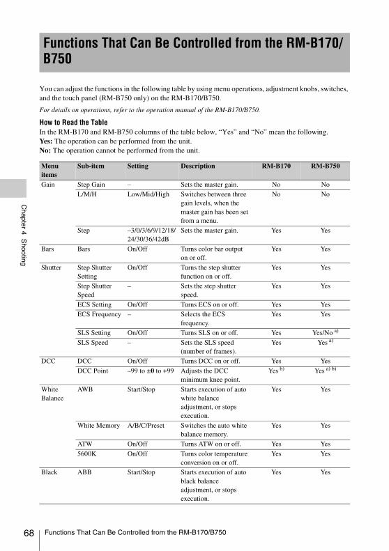
68
Chapter 4 S
hooting
You can adjust the functions in the following table by using menu operations, adjustment knobs, switches, and the touch panel (RM-B750 only) on the RM-B170/B750.
For details on operations, refer to the operation manual of the RM-B170/B750.
How to Read the TableIn the RM-B170 and RM-B750 columns of the table below, “Yes” and “No” mean the following.Yes: The operation can be performed from the unit.No: The operation cannot be performed from the unit.
Functions That Can Be Controlled from the RM-B170/B750
Menu items
Sub-item Setting Description RM-B170 RM-B750
Gain Step Gain – Sets the master gain. No No
L/M/H Low/Mid/High Switches between three gain levels, when the master gain has been set from a menu.
No No
Step –3/0/3/6/9/12/18/24/30/36/42dB
Sets the master gain. Yes Yes
Bars Bars On/Off Turns color bar output on or off.
Yes Yes
Shutter Step Shutter Setting
On/Off Turns the step shutter function on or off.
Yes Yes
Step Shutter Speed
– Sets the step shutter speed.
Yes Yes
ECS Setting On/Off Turns ECS on or off. Yes Yes
ECS Frequency – Selects the ECS frequency.
Yes Yes
SLS Setting On/Off Turns SLS on or off. Yes Yes/No a)
SLS Speed – Sets the SLS speed (number of frames).
Yes Yes a)
DCC DCC On/Off Turns DCC on or off. Yes Yes
DCC Point –99 to ±0 to +99 Adjusts the DCC minimum knee point.
Yes b) Yes a) b)
White Balance
AWB Start/Stop Starts execution of auto white balance adjustment, or stops execution.
Yes Yes
White Memory A/B/C/Preset Switches the auto white balance memory.
Yes Yes
ATW On/Off Turns ATW on or off. Yes Yes
5600K On/Off Turns color temperature conversion on or off.
Yes Yes
Black ABB Start/Stop Starts execution of auto black balance adjustment, or stops execution.
Yes Yes
Functions That Can Be Controlled from the RM-B170/B750
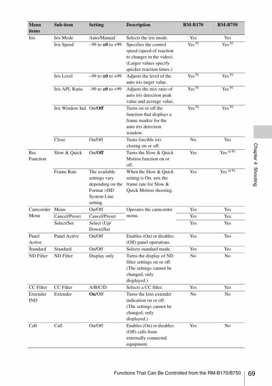
Chapter 4 S
hooting
Iris Iris Mode Auto/Manual Selects the iris mode. Yes Yes
Iris Speed –99 to ±0 to +99 Specifies the control speed (speed of reaction to changes in the video). (Larger values specify quicker reaction times.)
Yes b) Yes b)
Iris Level –99 to ±0 to +99 Adjusts the level of the auto iris target value.
Yes b) Yes b)
Iris APL Ratio –99 to ±0 to +99 Adjusts the mix ratio of auto iris detection peak value and average value.
Yes b) Yes b)
Iris Window Ind On/Off Turns on or off the function that displays a frame marker for the auto iris detection window.
Yes b) Yes b)
Close On/Off Turns forcible iris closing on or off.
No Yes
Rec Function
Slow & Quick On/Off Turns the Slow & Quick Motion function on or off.
Yes Yes a) b)
Frame Rate The available settings vary depending on the Format >HD System Line setting.
When the Slow & Quick setting is On, sets the frame rate for Slow & Quick Motion shooting.
Yes Yes a) b)
Camcorder Menu
Menu On/Off Operates the camcorder menu.
Yes Yes
Cancel/Preset Cancel/Preset Yes Yes
Select/Set Select (Up/Down)/Set
Yes Yes
Panel Active
Panel Active On/Off Enables (On) or disables (Off) panel operations.
Yes Yes
Standard Standard On/Off Selects standard mode. Yes Yes
ND Filter ND Filter Display only Turns the display of ND filter settings on or off. (The settings cannot be changed, only displayed.)
No No
CC Filter CC Filter A/B/C/D Selects a CC filter. Yes Yes
Extender IND
Extender On/Off Turns the lens extender indication on or off. (The settings cannot be changed, only displayed.)
No No
Call Call On/Off Enables (On) or disables (Off) calls from externally connected equipment.
Yes No
Menu items
Sub-item Setting Description RM-B170 RM-B750
Functions That Can Be Controlled from the RM-B170/B750 69
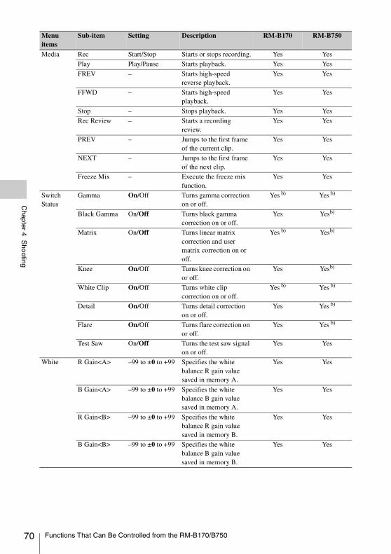
70
Chapter 4 S
hooting
Media Rec Start/Stop Starts or stops recording. Yes Yes
Play Play/Pause Starts playback. Yes Yes
FREV – Starts high-speed reverse playback.
Yes Yes
FFWD – Starts high-speed playback.
Yes Yes
Stop – Stops playback. Yes Yes
Rec Review – Starts a recording review.
Yes Yes
PREV – Jumps to the first frame of the current clip.
Yes Yes
NEXT – Jumps to the first frame of the next clip.
Yes Yes
Freeze Mix – Execute the freeze mix function.
Yes Yes
Switch Status
Gamma On/Off Turns gamma correction on or off.
Yes b) Yes b)
Black Gamma On/Off Turns black gamma correction on or off.
Yes Yesb)
Matrix On/Off Turns linear matrix correction and user matrix correction on or off.
Yes b) Yesb)
Knee On/Off Turns knee correction on or off.
Yes Yesb)
White Clip On/Off Turns white clip correction on or off.
Yes b) Yes b)
Detail On/Off Turns detail correction on or off.
Yes Yes b)
Flare On/Off Turns flare correction on or off.
Yes Yes b)
Test Saw On/Off Turns the test saw signal on or off.
Yes Yes
White R Gain<A> –99 to ±0 to +99 Specifies the white balance R gain value saved in memory A.
Yes Yes
B Gain<A> –99 to ±0 to +99 Specifies the white balance B gain value saved in memory A.
Yes Yes
R Gain<B> –99 to ±0 to +99 Specifies the white balance R gain value saved in memory B.
Yes Yes
B Gain<B> –99 to ±0 to +99 Specifies the white balance B gain value saved in memory B.
Yes Yes
Menu items
Sub-item Setting Description RM-B170 RM-B750
Functions That Can Be Controlled from the RM-B170/B750
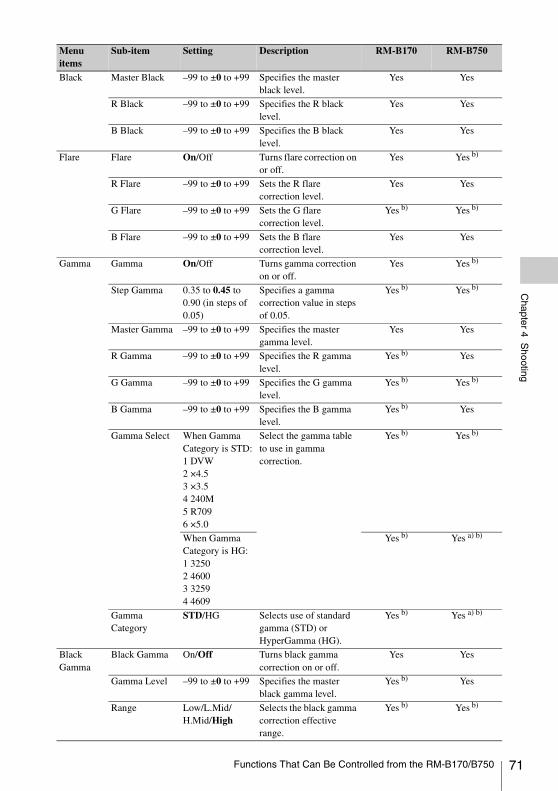
Chapter 4 S
hooting
Black Master Black –99 to ±0 to +99 Specifies the master black level.
Yes Yes
R Black –99 to ±0 to +99 Specifies the R black level.
Yes Yes
B Black –99 to ±0 to +99 Specifies the B black level.
Yes Yes
Flare Flare On/Off Turns flare correction on or off.
Yes Yes b)
R Flare –99 to ±0 to +99 Sets the R flare correction level.
Yes Yes
G Flare –99 to ±0 to +99 Sets the G flare correction level.
Yes b) Yes b)
B Flare –99 to ±0 to +99 Sets the B flare correction level.
Yes Yes
Gamma Gamma On/Off Turns gamma correction on or off.
Yes Yes b)
Step Gamma 0.35 to 0.45 to 0.90 (in steps of 0.05)
Specifies a gamma correction value in steps of 0.05.
Yes b) Yes b)
Master Gamma –99 to ±0 to +99 Specifies the master gamma level.
Yes Yes
R Gamma –99 to ±0 to +99 Specifies the R gamma level.
Yes b) Yes
G Gamma –99 to ±0 to +99 Specifies the G gamma level.
Yes b) Yes b)
B Gamma –99 to ±0 to +99 Specifies the B gamma level.
Yes b) Yes
Gamma Select When Gamma Category is STD:1 DVW2 ×4.53 ×3.54 240M5 R7096 ×5.0
Select the gamma table to use in gamma correction.
Yes b) Yes b)
When Gamma Category is HG: 1 32502 46003 32594 4609
Yes b) Yes a) b)
Gamma Category
STD/HG Selects use of standard gamma (STD) or HyperGamma (HG).
Yes b) Yes a) b)
Black Gamma
Black Gamma On/Off Turns black gamma correction on or off.
Yes Yes
Gamma Level –99 to ±0 to +99 Specifies the master black gamma level.
Yes b) Yes
Range Low/L.Mid/H.Mid/High
Selects the black gamma correction effective range.
Yes b) Yes b)
Menu items
Sub-item Setting Description RM-B170 RM-B750
Functions That Can Be Controlled from the RM-B170/B750 71
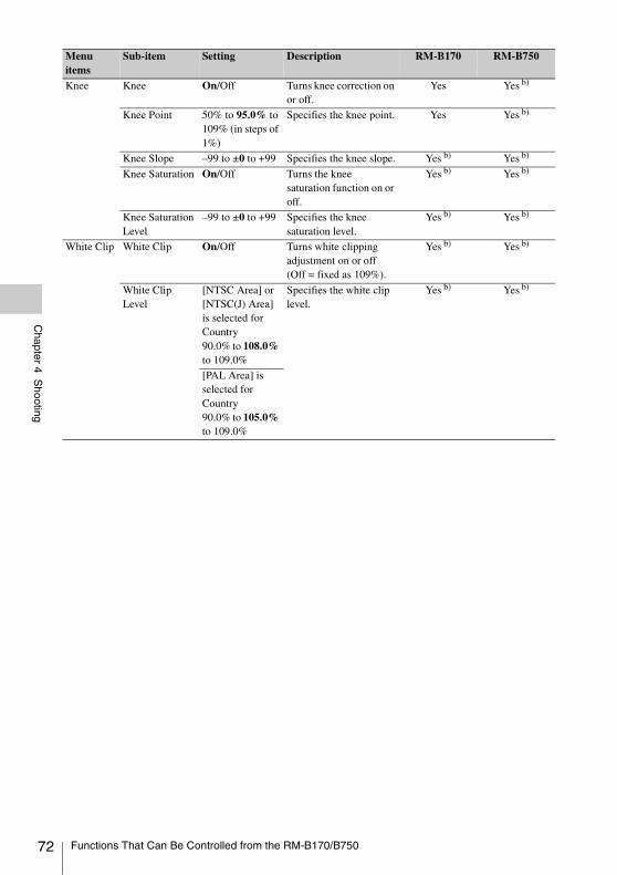
72
Chapter 4 S
hooting
Knee Knee On/Off Turns knee correction on or off.
Yes Yes b)
Knee Point 50% to 95.0% to 109% (in steps of 1%)
Specifies the knee point. Yes Yes b)
Knee Slope –99 to ±0 to +99 Specifies the knee slope. Yes b) Yes b)
Knee Saturation On/Off Turns the knee saturation function on or off.
Yes b) Yes b)
Knee Saturation Level
–99 to ±0 to +99 Specifies the knee saturation level.
Yes b) Yes b)
White Clip White Clip On/Off Turns white clipping adjustment on or off (Off = fixed as 109%).
Yes b) Yes b)
White Clip Level
[NTSC Area] or [NTSC(J) Area] is selected for Country90.0% to 108.0% to 109.0%
Specifies the white clip level.
Yes b) Yes b)
[PAL Area] is selected for Country90.0% to 105.0% to 109.0%
Menu items
Sub-item Setting Description RM-B170 RM-B750
Functions That Can Be Controlled from the RM-B170/B750
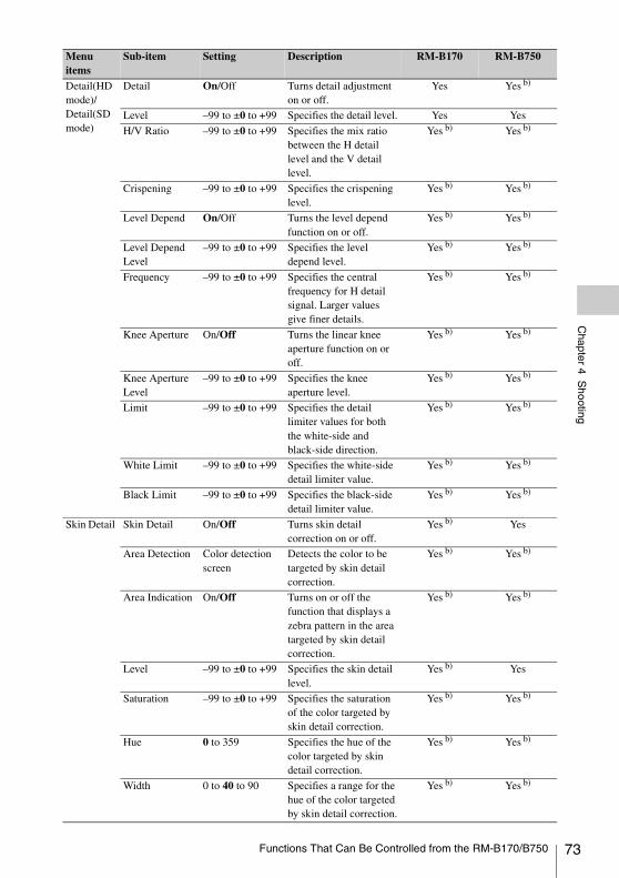
Chapter 4 S
hooting
Detail(HD mode)/Detail(SD mode)
Detail On/Off Turns detail adjustment on or off.
Yes Yes b)
Level –99 to ±0 to +99 Specifies the detail level. Yes Yes
H/V Ratio –99 to ±0 to +99 Specifies the mix ratio between the H detail level and the V detail level.
Yes b) Yes b)
Crispening –99 to ±0 to +99 Specifies the crispening level.
Yes b) Yes b)
Level Depend On/Off Turns the level depend function on or off.
Yes b) Yes b)
Level Depend Level
–99 to ±0 to +99 Specifies the level depend level.
Yes b) Yes b)
Frequency –99 to ±0 to +99 Specifies the central frequency for H detail signal. Larger values give finer details.
Yes b) Yes b)
Knee Aperture On/Off Turns the linear knee aperture function on or off.
Yes b) Yes b)
Knee Aperture Level
–99 to ±0 to +99 Specifies the knee aperture level.
Yes b) Yes b)
Limit –99 to ±0 to +99 Specifies the detail limiter values for both the white-side and black-side direction.
Yes b) Yes b)
White Limit –99 to ±0 to +99 Specifies the white-side detail limiter value.
Yes b) Yes b)
Black Limit –99 to ±0 to +99 Specifies the black-side detail limiter value.
Yes b) Yes b)
Skin Detail Skin Detail On/Off Turns skin detail correction on or off.
Yes b) Yes
Area Detection Color detection screen
Detects the color to be targeted by skin detail correction.
Yes b) Yes b)
Area Indication On/Off Turns on or off the function that displays a zebra pattern in the area targeted by skin detail correction.
Yes b) Yes b)
Level –99 to ±0 to +99 Specifies the skin detail level.
Yes b) Yes
Saturation –99 to ±0 to +99 Specifies the saturation of the color targeted by skin detail correction.
Yes b) Yes b)
Hue 0 to 359 Specifies the hue of the color targeted by skin detail correction.
Yes b) Yes b)
Width 0 to 40 to 90 Specifies a range for the hue of the color targeted by skin detail correction.
Yes b) Yes b)
Menu items
Sub-item Setting Description RM-B170 RM-B750
Functions That Can Be Controlled from the RM-B170/B750 73
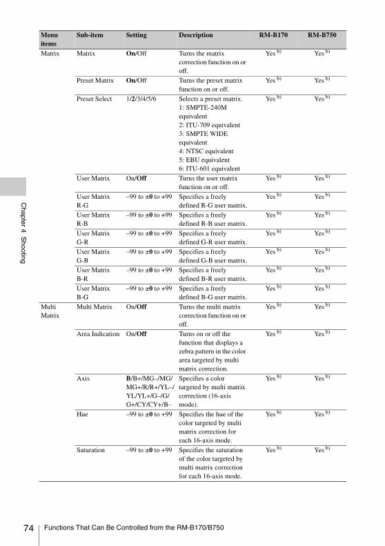
74
Chapter 4 S
hooting
Matrix Matrix On/Off Turns the matrix correction function on or off.
Yes b) Yes b)
Preset Matrix On/Off Turns the preset matrix function on or off.
Yes b) Yes b)
Preset Select 1/2/3/4/5/6 Selects a preset matrix.1: SMPTE-240M equivalent2: ITU-709 equivalent3: SMPTE WIDE equivalent4: NTSC equivalent5: EBU equivalent6: ITU-601 equivalent
Yes b) Yes b)
User Matrix On/Off Turns the user matrix function on or off.
Yes b) Yes b)
User Matrix R-G
–99 to ±0 to +99 Specifies a freely defined R-G user matrix.
Yes b) Yes b)
User Matrix R-B
–99 to ±0 to +99 Specifies a freely defined R-B user matrix.
Yes b) Yes b)
User Matrix G-R
–99 to ±0 to +99 Specifies a freely defined G-R user matrix.
Yes b) Yes b)
User Matrix G-B
–99 to ±0 to +99 Specifies a freely defined G-B user matrix.
Yes b) Yes b)
User Matrix B-R
–99 to ±0 to +99 Specifies a freely defined B-R user matrix.
Yes b) Yes b)
User Matrix B-G
–99 to ±0 to +99 Specifies a freely defined B-G user matrix.
Yes b) Yes b)
Multi Matrix
Multi Matrix On/Off Turns the multi matrix correction function on or off.
Yes b) Yes b)
Area Indication On/Off Turns on or off the function that displays a zebra pattern in the color area targeted by multi matrix correction.
Yes b) Yes b)
Axis B/B+/MG–/MG/MG+/R/R+/YL–/YL/YL+/G–/G/G+/CY/CY+/B–
Specifies a color targeted by multi matrix correction (16-axis mode).
Yes b) Yes b)
Hue –99 to ±0 to +99 Specifies the hue of the color targeted by multi matrix correction for each 16-axis mode.
Yes b) Yes b)
Saturation –99 to ±0 to +99 Specifies the saturation of the color targeted by multi matrix correction for each 16-axis mode.
Yes b) Yes b)
Menu items
Sub-item Setting Description RM-B170 RM-B750
Functions That Can Be Controlled from the RM-B170/B750
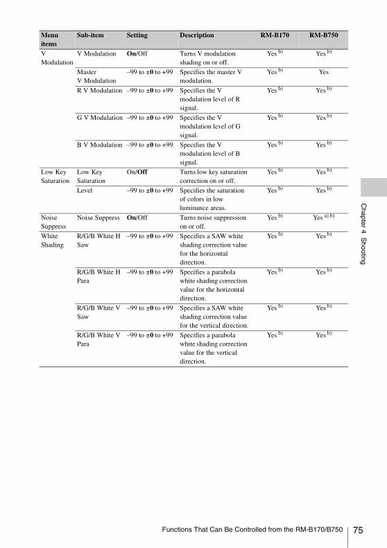
Chapter 4 S
hooting
V Modulation
V Modulation On/Off Turns V modulation shading on or off.
Yes b) Yes b)
Master V Modulation
–99 to ±0 to +99 Specifies the master V modulation.
Yes b) Yes
R V Modulation –99 to ±0 to +99 Specifies the V modulation level of R signal.
Yes b) Yes b)
G V Modulation –99 to ±0 to +99 Specifies the V modulation level of G signal.
Yes b) Yes b)
B V Modulation –99 to ±0 to +99 Specifies the V modulation level of B signal.
Yes b) Yes b)
Low Key Saturation
Low Key Saturation
On/Off Turns low key saturation correction on or off.
Yes b) Yes b)
Level –99 to ±0 to +99 Specifies the saturation of colors in low luminance areas.
Yes b) Yes b)
Noise Suppress
Noise Suppress On/Off Turns noise suppression on or off.
Yes b) Yes a) b)
White Shading
R/G/B White H Saw
–99 to ±0 to +99 Specifies a SAW white shading correction value for the horizontal direction.
Yes b) Yes b)
R/G/B White H Para
–99 to ±0 to +99 Specifies a parabola white shading correction value for the horizontal direction.
Yes b) Yes b)
R/G/B White V Saw
–99 to ±0 to +99 Specifies a SAW white shading correction value for the vertical direction.
Yes b) Yes b)
R/G/B White V Para
–99 to ±0 to +99 Specifies a parabola white shading correction value for the vertical direction.
Yes b) Yes b)
Menu items
Sub-item Setting Description RM-B170 RM-B750
Functions That Can Be Controlled from the RM-B170/B750 75
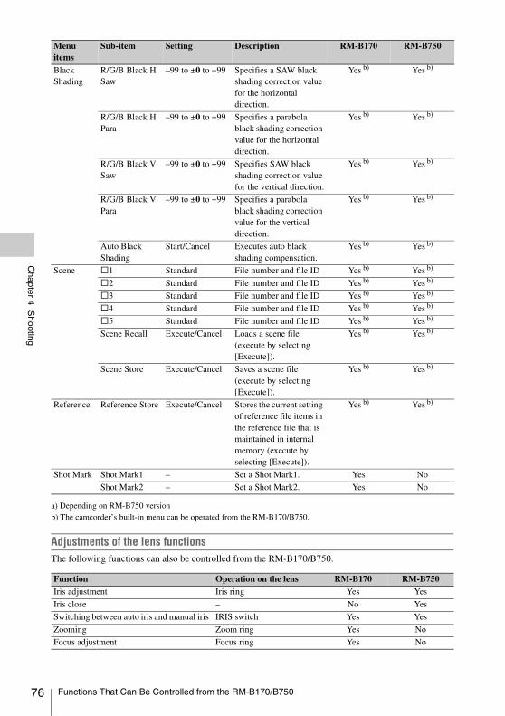
76
Chapter 4 S
hooting
a) Depending on RM-B750 versionb) The camcorder’s built-in menu can be operated from the RM-B170/B750.
Adjustments of the lens functionsThe following functions can also be controlled from the RM-B170/B750.
Black Shading
R/G/B Black H Saw
–99 to ±0 to +99 Specifies a SAW black shading correction value for the horizontal direction.
Yes b) Yes b)
R/G/B Black H Para
–99 to ±0 to +99 Specifies a parabola black shading correction value for the horizontal direction.
Yes b) Yes b)
R/G/B Black V Saw
–99 to ±0 to +99 Specifies SAW black shading correction value for the vertical direction.
Yes b) Yes b)
R/G/B Black V Para
–99 to ±0 to +99 Specifies a parabola black shading correction value for the vertical direction.
Yes b) Yes b)
Auto Black Shading
Start/Cancel Executes auto black shading compensation.
Yes b) Yes b)
Scene s1 Standard File number and file ID Yes b) Yes b)
s2 Standard File number and file ID Yes b) Yes b)
s3 Standard File number and file ID Yes b) Yes b)
s4 Standard File number and file ID Yes b) Yes b)
s5 Standard File number and file ID Yes b) Yes b)
Scene Recall Execute/Cancel Loads a scene file (execute by selecting [Execute]).
Yes b) Yes b)
Scene Store Execute/Cancel Saves a scene file (execute by selecting [Execute]).
Yes b) Yes b)
Reference Reference Store Execute/Cancel Stores the current setting of reference file items in the reference file that is maintained in internal memory (execute by selecting [Execute]).
Yes b) Yes b)
Shot Mark Shot Mark1 – Set a Shot Mark1. Yes No
Shot Mark2 – Set a Shot Mark2. Yes No
Function Operation on the lens RM-B170 RM-B750Iris adjustment Iris ring Yes Yes
Iris close – No Yes
Switching between auto iris and manual iris IRIS switch Yes Yes
Zooming Zoom ring Yes No
Focus adjustment Focus ring Yes No
Menu items
Sub-item Setting Description RM-B170 RM-B750
Functions That Can Be Controlled from the RM-B170/B750
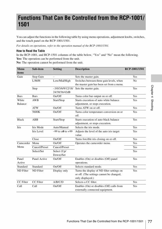
Chapter 4 S
hooting
You can adjust the functions in the following table by using menu operations, adjustment knobs, switches, and the touch panel on the RCP-1001/1501.
For details on operations, refer to the operation manual of the RCP-1001/1501.
How to Read the TableIn the RCP-1001, and RCP-1501 columns of the table below, “Yes” and “No” mean the following.Yes: The operation can be performed from the unit.No: The operation cannot be performed from the unit.
Functions That Can Be Controlled from the RCP-1001/1501
Menu items
Sub-item Setting Description RCP-1001/1501
Gain Step Gain – Sets the master gain. Yes
L/M/H Low/Mid/High Switches between three gain levels, when the master gain has been set from a menu.
No
Step –3/0/3/6/9/12/18/24/30/36/42dB
Sets the master gain. Yes
Bars Bars On/Off Turns color bar output on or off. Yes
White Balance
AWB Start/Stop Starts execution of auto white balance adjustment, or stops execution.
Yes
ATW On/Off Turns ATW on or off. Yes
5600K On/Off Turns color temperature conversion on or off.
Yes
Black ABB Start/Stop Starts execution of auto black balance adjustment, or stops execution.
Yes
Iris Iris Mode Auto/Manual Selects the iris mode. Yes
Iris Level –99 to ±0 to +99 Adjusts the level of the auto iris target value.
Yes
Close On/Off Turns forcible iris closing on or off. Yes
Camcorder Menu
Menu On/Off Operates the camcorder menu. Yes
Cancel/Preset Cancel/Preset Yes
Select/Set Select (Up/Down)/Set
Yes
Panel Active
Panel Active On/Off Enables (On) or disables (Off) panel operations.
Yes
Standard Standard On/Off Selects standard mode. Yes
ND Filter ND Filter Display only Turns the display of ND filter settings on or off. (The settings cannot be changed, only displayed.)
Yes
CC Filter CC Filter A/B/C/D Selects a CC filter. Yes
Call Call On/Off Enables (On) or disables (Off) calls from externally connected equipment.
Yes
Functions That Can Be Controlled from the RCP-1001/1501 77
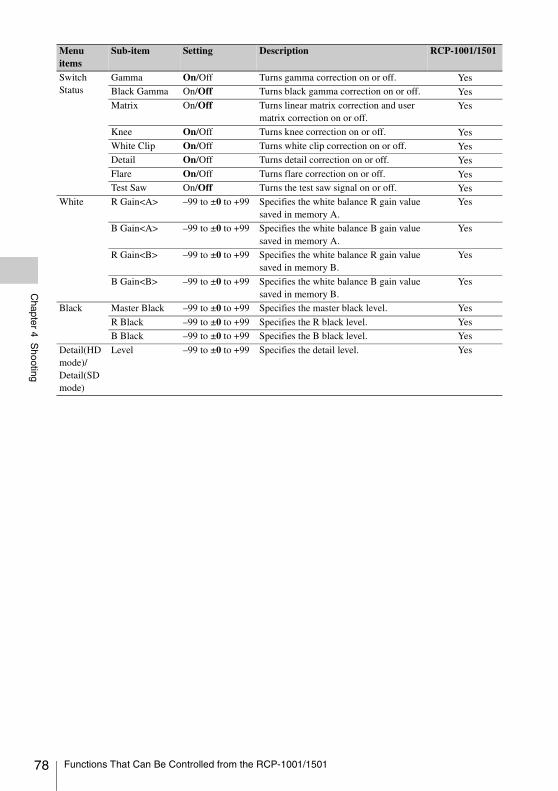
78
Chapter 4 S
hooting
Switch Status
Gamma On/Off Turns gamma correction on or off. YesBlack Gamma On/Off Turns black gamma correction on or off. YesMatrix On/Off Turns linear matrix correction and user
matrix correction on or off.Yes
Knee On/Off Turns knee correction on or off. YesWhite Clip On/Off Turns white clip correction on or off. YesDetail On/Off Turns detail correction on or off. YesFlare On/Off Turns flare correction on or off. YesTest Saw On/Off Turns the test saw signal on or off. Yes
White R Gain<A> –99 to ±0 to +99 Specifies the white balance R gain value saved in memory A.
Yes
B Gain<A> –99 to ±0 to +99 Specifies the white balance B gain value saved in memory A.
Yes
R Gain<B> –99 to ±0 to +99 Specifies the white balance R gain value saved in memory B.
Yes
B Gain<B> –99 to ±0 to +99 Specifies the white balance B gain value saved in memory B.
Yes
Black Master Black –99 to ±0 to +99 Specifies the master black level. Yes
R Black –99 to ±0 to +99 Specifies the R black level. Yes
B Black –99 to ±0 to +99 Specifies the B black level. Yes
Detail(HD mode)/Detail(SD mode)
Level –99 to ±0 to +99 Specifies the detail level. Yes
Menu items
Sub-item Setting Description RCP-1001/1501
Functions That Can Be Controlled from the RCP-1001/1501
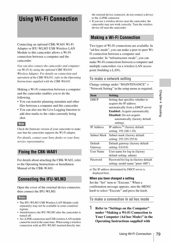
Chapter 4 S
hooting
Connecting an optional CBK-WA01 Wi-Fi Adapter or IFU-WLM3 USB Wireless LAN Module to this camcorder allows a Wi-Fi connection between a computer and the camcorder.
You can also connect the camcorder and computer via Wi-Fi by using the optional CBK-WA101 Wireless Adapter. For details on connection and operation of the CBK-WA101, refer to the Operating Instructions supplied with the CBK-WA101.
Making a Wi-Fi connection between a computer and the camcorder enables you to do the following.• You can transfer planning metadata and other
files between a computer and this camcorder.• You can also use the Live Logging function to
add shot marks to the video currently being shot.
Note
Check the firmware version of your camcorder to make sure that the camcorder supports the Wi-Fi adapter.
For details, contact your Sony dealer or your Sony service representative.
For details about attaching the CBK-WA01, refer to the Operating Instructions or Installation Manual of the CBK-WA01.
Open the cover of the external device connector, then connect the IFU-WLM3.
Notes
• The IFU-WLM3 USB Wireless LAN Module (sold separately) may not be available in some countries/regions.
• Attach/remove the IFU-WLM3 after the camcorder is turned off.
• An i.LINK connection and USB wireless LAN module cannot be used at the same time. When using a wireless connection with an IFU-WLM3 inserted directly into
the external device connector, do not connect a device to the i.LINK connector.
• If you use a wireless device near the camcorder, the camcorder may not work correctly. Turn the wireless device off near the camcorder.
Two types of Wi-Fi connections are available. In “ad-hoc mode”, you can make a peer-to-peer Wi-Fi connection between a computer and camcorder. In “infrastructure mode”, you can make Wi-Fi connections between a computer and multiple camcorders via a wireless LAN access point (building a LAN).
To make a network settingChange settings under “MAINTENANCE” > “Network Setting” in the setup menu as required.
a) The IP address determined by DHCP server is displayed here.
When you have changed a settingSet the “Set” item to “Execute.” When a confirmation message appears, turn the MENU knob to select “Execute” and press the knob.
To make a connection in ad hoc mode
1 Refer to “Settings on the Computer” under “Making a Wi-Fi Connection to Your Computer (Ad hoc Mode)” in the Operating Instructions supplied with
Using Wi-Fi Connection
Fixing the CBK-WA01
Connecting the IFU-WLM3
Making a Wi-Fi Connection
Item SettingDHCP Setting that specifies whether to
acquire the IP address automatically from a DHCP serverEnabled: Acquire automatically.Disabled: Do not acquire
automatically (factory default setting).
IP Address IP address a) (factory default setting: 192.168.1.10)
Subnet Mask Subnet mask (factory default setting: 255.255.255.0)
Default Gateway
Default gateway (factory default setting: 0.0.0.0)
User Name User name for log-in (factory default setting: admin)
Password Password for log-in (factory default setting: model name “pmw-400”)
Using Wi-Fi Connection 79
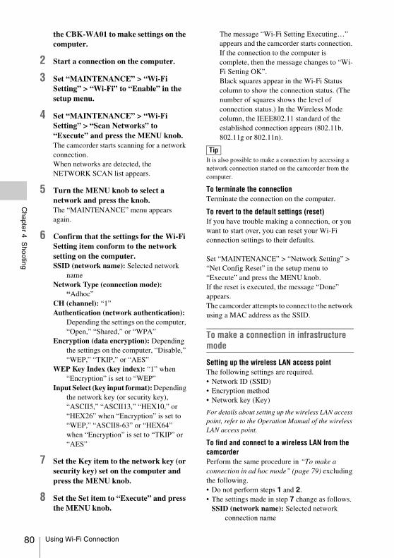
80
Chapter 4 S
hooting
the CBK-WA01 to make settings on the computer.
2 Start a connection on the computer.
3 Set “MAINTENANCE” > “Wi-Fi Setting” > “Wi-Fi” to “Enable” in the setup menu.
4 Set “MAINTENANCE” > “Wi-Fi Setting” > “Scan Networks” to “Execute” and press the MENU knob.The camcorder starts scanning for a network connection.When networks are detected, the NETWORK SCAN list appears.
5 Turn the MENU knob to select a network and press the knob.The “MAINTENANCE” menu appears again.
6 Confirm that the settings for the Wi-Fi Setting item conform to the network setting on the computer.SSID (network name): Selected network
nameNetwork Type (connection mode):
“Adhoc”CH (channel): “1”Authentication (network authentication):
Depending the settings on the computer, “Open,” “Shared,” or “WPA”
Encryption (data encryption): Depending the settings on the computer, “Disable,” “WEP,” “TKIP,” or “AES”
WEP Key Index (key index): “1” when “Encryption” is set to “WEP”
Input Select (key input format): Depending the network key (or security key), “ASCII5,” “ASCII13,” “HEX10,” or “HEX26” when “Encryption” is set to “WEP,” “ASCII8-63” or “HEX64” when “Encryption” is set to “TKIP” or “AES”
7 Set the Key item to the network key (or security key) set on the computer and press the MENU knob.
8 Set the Set item to “Execute” and press the MENU knob.
The message “Wi-Fi Setting Executing…” appears and the camcorder starts connection. If the connection to the computer is complete, then the message changes to “Wi-Fi Setting OK”. Black squares appear in the Wi-Fi Status column to show the connection status. (The number of squares shows the level of connection status.) In the Wireless Mode column, the IEEE802.11 standard of the established connection appears (802.11b, 802.11g or 802.11n).
It is also possible to make a connection by accessing a network connection started on the camcorder from the computer.
To terminate the connectionTerminate the connection on the computer.
To revert to the default settings (reset)If you have trouble making a connection, or you want to start over, you can reset your Wi-Fi connection settings to their defaults.
Set “MAINTENANCE” > “Network Setting” > “Net Config Reset” in the setup menu to “Execute” and press the MENU knob.If the reset is executed, the message “Done” appears.The camcorder attempts to connect to the network using a MAC address as the SSID.
To make a connection in infrastructure mode
Setting up the wireless LAN access pointThe following settings are required.• Network ID (SSID)• Encryption method• Network key (Key)
For details about setting up the wireless LAN access point, refer to the Operation Manual of the wireless LAN access point.
To find and connect to a wireless LAN from the camcorderPerform the same procedure in “To make a connection in ad hoc mode” (page 79) excluding the following.• Do not perform steps 1 and 2.• The settings made in step 7 change as follows.
SSID (network name): Selected network connection name
Tip
Using Wi-Fi Connection
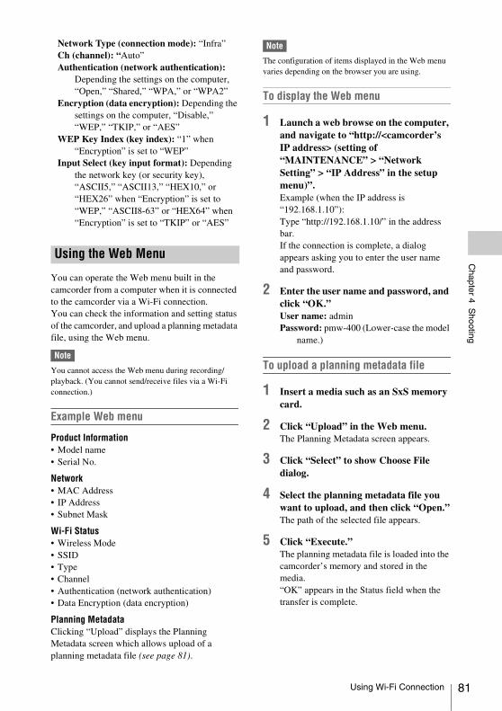
Chapter 4 S
hooting
Network Type (connection mode): “Infra”Ch (channel): “Auto”Authentication (network authentication):
Depending the settings on the computer, “Open,” “Shared,” “WPA,” or “WPA2”
Encryption (data encryption): Depending the settings on the computer, “Disable,” “WEP,” “TKIP,” or “AES”
WEP Key Index (key index): “1” when “Encryption” is set to “WEP”
Input Select (key input format): Depending the network key (or security key), “ASCII5,” “ASCII13,” “HEX10,” or “HEX26” when “Encryption” is set to “WEP,” “ASCII8-63” or “HEX64” when “Encryption” is set to “TKIP” or “AES”
You can operate the Web menu built in the camcorder from a computer when it is connected to the camcorder via a Wi-Fi connection.You can check the information and setting status of the camcorder, and upload a planning metadata file, using the Web menu.
Note
You cannot access the Web menu during recording/playback. (You cannot send/receive files via a Wi-Fi connection.)
Example Web menu
Product Information• Model name• Serial No.
Network• MAC Address• IP Address• Subnet Mask
Wi-Fi Status• Wireless Mode• SSID• Type• Channel• Authentication (network authentication)• Data Encryption (data encryption)
Planning MetadataClicking “Upload” displays the Planning Metadata screen which allows upload of a planning metadata file (see page 81).
Note
The configuration of items displayed in the Web menu varies depending on the browser you are using.
To display the Web menu
1 Launch a web browse on the computer, and navigate to “http://<camcorder’s IP address> (setting of “MAINTENANCE” > “Network Setting” > “IP Address” in the setup menu)”.Example (when the IP address is “192.168.1.10”): Type “http://192.168.1.10/” in the address bar.If the connection is complete, a dialog appears asking you to enter the user name and password.
2 Enter the user name and password, and click “OK.”User name: adminPassword: pmw-400 (Lower-case the model
name.)
To upload a planning metadata file
1 Insert a media such as an SxS memory card.
2 Click “Upload” in the Web menu.The Planning Metadata screen appears.
3 Click “Select” to show Choose File dialog.
4 Select the planning metadata file you want to upload, and then click “Open.”The path of the selected file appears.
5 Click “Execute.”The planning metadata file is loaded into the camcorder’s memory and stored in the media.“OK” appears in the Status field when the transfer is complete.
Using the Web Menu
Using Wi-Fi Connection 81
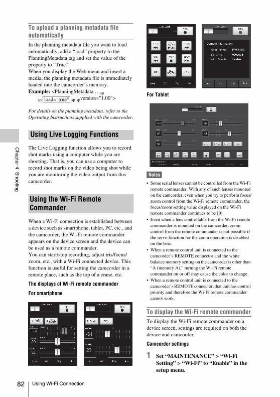
82
Chapter 4 S
hooting
To upload a planning metadata file automaticallyIn the planning metadata file you want to load automatically, add a “load” property to the PlanningMetadata tag and set the value of the property to “True.”When you display the Web menu and insert a media, the planning metadata file is immediately loaded into the camcorder’s memory.Example: <PlanningMetadata …sp
sp sp spversion="1.00">
For details on the planning metadata, refer to the Operating Instructions supplied with the camcorder.
The Live Logging function allows you to record shot marks using a computer while you are shooting. That is, you can use a computer to record shot marks on the video being shot while you are monitoring the video output from this camcorder.
When a Wi-Fi connection is established between a device such as smartphone, tablet, PC, etc., and the camcorder, the Wi-Fi remote commander appears on the device screen and the device can be used as a remote commander. You can start/stop recording, adjust iris/focus/zoom, etc., with a Wi-Fi connected device. This function is useful for setting the camcorder in a remote place, such as the top of a crane, etc.
The displays of Wi-Fi remote commander
For smartphone
For Tablet
Notes
• Some serial lenses cannot be controlled from the Wi-Fi remote commander. With any of such lenses mounted on the camcorder, even when you try to perform focus/zoom control from the Wi-Fi remote commander, the focus/zoom setting value displayed on the Wi-Fi remote commander continues to be [0].
• Even when a lens controllable from the Wi-Fi remote commander is mounted on the camcorder, zoom control from the remote commander is not possible if the servo function for the zoom operation is disabled on the lens.
• When a remote control unit is connected to the camcorder’s REMOTE connector and the white balance memory setting on the camcorder is other than “A (memory A),” turning the Wi-Fi remote commander on or off may cause the color to change.
• When a remote control unit is connected to the camcorder’s REMOTE connector, that unit has control priority and therefore the Wi-Fi remote commander cannot work.
To display the Wi-Fi remote commanderTo display the Wi-Fi remote commander on a device screen, settings are required on both the device and camcorder.
Camcorder settings
1 Set “MAINTENANCE” > “Wi-Fi Setting” > “Wi-Fi” to “Enable” in the setup menu.
Using Live Logging Functions
Using the Wi-Fi Remote Commander
load="true"
Using Wi-Fi Connection
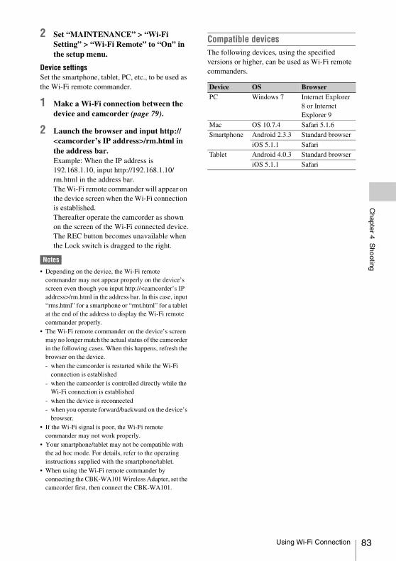
Chapter 4 S
hooting
2 Set “MAINTENANCE” > “Wi-Fi Setting” > “Wi-Fi Remote” to “On” in the setup menu.
Device settingsSet the smartphone, tablet, PC, etc., to be used as the Wi-Fi remote commander.
1 Make a Wi-Fi connection between the device and camcorder (page 79).
2 Launch the browser and input http://<camcorder’s IP address>/rm.html in the address bar.Example: When the IP address is 192.168.1.10, input http://192.168.1.10/rm.html in the address bar.The Wi-Fi remote commander will appear on the device screen when the Wi-Fi connection is established.Thereafter operate the camcorder as shown on the screen of the Wi-Fi connected device.The REC button becomes unavailable when the Lock switch is dragged to the right.
Notes
• Depending on the device, the Wi-Fi remote commander may not appear properly on the device’s screen even though you input http://<camcorder’s IP address>/rm.html in the address bar. In this case, input “rms.html” for a smartphone or “rmt.html” for a tablet at the end of the address to display the Wi-Fi remote commander properly.
• The Wi-Fi remote commander on the device’s screen may no longer match the actual status of the camcorder in the following cases. When this happens, refresh the browser on the device.- when the camcorder is restarted while the Wi-Fi
connection is established- when the camcorder is controlled directly while the
Wi-Fi connection is established- when the device is reconnected- when you operate forward/backward on the device’s
browser.• If the Wi-Fi signal is poor, the Wi-Fi remote
commander may not work properly.• Your smartphone/tablet may not be compatible with
the ad hoc mode. For details, refer to the operating instructions supplied with the smartphone/tablet.
• When using the Wi-Fi remote commander by connecting the CBK-WA101 Wireless Adapter, set the camcorder first, then connect the CBK-WA101.
Compatible devicesThe following devices, using the specified versions or higher, can be used as Wi-Fi remote commanders.
Device OS BrowserPC Windows 7 Internet Explorer
8 or InternetExplorer 9
Mac OS 10.7.4 Safari 5.1.6
Smartphone Android 2.3.3 Standard browser
iOS 5.1.1 Safari
Tablet Android 4.0.3 Standard browser
iOS 5.1.1 Safari
Using Wi-Fi Connection 83
84
Chapter 4 S
hooting
1 Attach a fully charged battery pack (see page 29).
2 Load one or two SxS memory cards (see page 60).If you load two cards, the camcorder switches automatically to the second card when the first card becomes full.
3 Set the camcorder’s POWER switch (see page 11) to ON.
4 Make the following settings.Marker display: On (see page 120)Iris: Auto (see page 52)Zoom: Auto (see page 53)Camera output: Select the picture currently
being shot (camera picture), and turn the DCC function on (see page 15).
Timecode advance mode: F-RUN (Free Run) or R-RUN (Rec Run) (see page 56)
Audio input channel selection: Auto (see page 21)
5 Push the AUTO W/B BAL switch to the BLACK side to adjust the black balance (see page 47).
6 Select a filter according to the lighting conditions, and adjust the white balance (see page 48).
7 Point the camcorder at the subject, and adjust the focus (see page 54) and zoom.
8 If you are using the electronic shutter, select an appropriate shutter mode and speed (see page 50).
9 Do one of the following to start recording.- Press the REC START button (see
page 13).- Press the VTR button on the lens (see
page 24).
- Turn on the assignable switch to which the Rec function has been assigned (see page 159).
During recording, the TALLY indicators, the tally indicator on the front panel of the viewfinder, and the REC indication on the viewfinder screen light. Adjust the zoom and focus as required.
Notes
• Never remove the battery pack while the camcorder is recording (while the ACCESS lamp on the right-side panel is lit in blue and the ACCESS lamp in the card slot section is lit in orange). Doing so risks the loss of several seconds of data before the recording was interrupted, because internal processing will not end normally.
• The playback control buttons (EJECT, F REV, F FWD, NEXT, PREV, PLAY/PAUSE, STOP) do not function during recording.
10 To stop recording, perform one of the operations listed in step 9.The TALLY indicators, the tally indicator on the front panel of the viewfinder, and the REC indication on the viewfinder screen go out, and camcorder enters recording standby (STBY) mode.A clip is created from the video and audio data and the metadata recorded between steps 9 and 10.
To check the recording (recording review)With the camcorder in recording standby (STBY) mode, turn on the assignable switch to which the Rec Review function or the Freeze Mix function has been assigned (see page 158).The camcorder plays the entire last clip, or the last few seconds of that clip (3 seconds or 10 seconds), and then returns to standby mode.When the Rec Review function is assigned to the RET button on the lens, you can also conduct a review by using the RET button.
11 Repeat steps 9 and 10 to continue recording.With each repetition, another clip is created on the memory card.
Basic Operations
Basic Operations
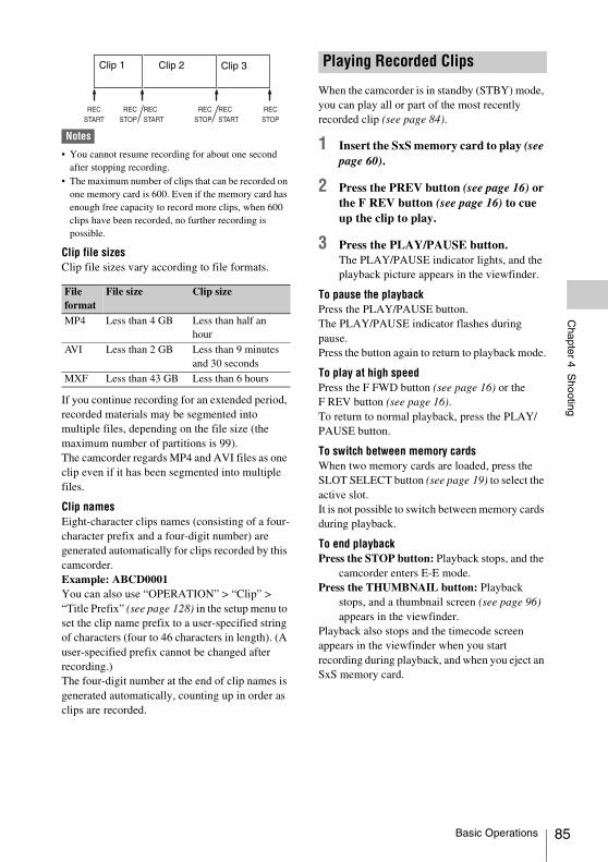
Chapter 4 S
hooting
Notes
• You cannot resume recording for about one second after stopping recording.
• The maximum number of clips that can be recorded on one memory card is 600. Even if the memory card has enough free capacity to record more clips, when 600 clips have been recorded, no further recording is possible.
Clip file sizesClip file sizes vary according to file formats.
If you continue recording for an extended period, recorded materials may be segmented into multiple files, depending on the file size (the maximum number of partitions is 99). The camcorder regards MP4 and AVI files as one clip even if it has been segmented into multiple files.
Clip namesEight-character clips names (consisting of a four-character prefix and a four-digit number) are generated automatically for clips recorded by this camcorder.Example: ABCD0001You can also use “OPERATION” > “Clip” > “Title Prefix” (see page 128) in the setup menu to set the clip name prefix to a user-specified string of characters (four to 46 characters in length). (A user-specified prefix cannot be changed after recording.)The four-digit number at the end of clip names is generated automatically, counting up in order as clips are recorded.
When the camcorder is in standby (STBY) mode, you can play all or part of the most recently recorded clip (see page 84).
1 Insert the SxS memory card to play (see page 60).
2 Press the PREV button (see page 16) or the F REV button (see page 16) to cue up the clip to play.
3 Press the PLAY/PAUSE button.The PLAY/PAUSE indicator lights, and the playback picture appears in the viewfinder.
To pause the playbackPress the PLAY/PAUSE button.The PLAY/PAUSE indicator flashes during pause.Press the button again to return to playback mode.
To play at high speedPress the F FWD button (see page 16) or the F REV button (see page 16).To return to normal playback, press the PLAY/PAUSE button.
To switch between memory cardsWhen two memory cards are loaded, press the SLOT SELECT button (see page 19) to select the active slot.It is not possible to switch between memory cards during playback.
To end playbackPress the STOP button: Playback stops, and the
camcorder enters E-E mode.Press the THUMBNAIL button: Playback
stops, and a thumbnail screen (see page 96) appears in the viewfinder.
Playback also stops and the timecode screen appears in the viewfinder when you start recording during playback, and when you eject an SxS memory card.
File format
File size Clip size
MP4 Less than 4 GB Less than half an hour
AVI Less than 2 GB Less than 9 minutes and 30 seconds
MXF Less than 43 GB Less than 6 hours
Clip 1 Clip 2 Clip 3 Playing Recorded Clips
Basic Operations 85
86
Chapter 4 S
hooting
You can use the assignable switches to delete the last recorded clips (Last Clip DEL function).
You can also use the THUMBNAIL menu to delete all recorded clips (All Clips DEL function) or to delete selected clips. For details, see “Deleting Clips” (page 105).
1 Turn on the assignable switch to which the Last Clip DEL function has been assigned (see page 159).A confirmation message appears.
2 Turn the MENU knob to select “Execute,” and then press the knob.
On this camcorder, two types of shot marks are available in HD mode. You can record them at user-specified positions to make it easier for editors to cue up those positions. You can record up to 127 shot marks per clip.
Note
Shot marks cannot be recorded in SD mode.
You can also use the THUMBNAIL menu to add and delete shot marks in clips. For details, see “Adding and Deleting Shot Marks (UDF/exFAT/FAT-HD Mode Only)” (page 107).
To record shot marksDo one of the following.• Turn on an assignable switch to which Shot
Mark 1 or Shot Mark 2 has been assigned (see page 158).
• If Lens RET has been assigned to the RET button on the lens, operate as follows.To record shot mark 1: Press the RET button
once.To record shot mark 2: Press the RET button
twice in quick succession.
When a shot mark is recorded, a “Shot Mark 1” or “Shot Mark 2” indication appears in the viewfinder for about three seconds near the timecode indication.
To make it easier for editors to select good clips, you can set OK marks in clips recorded in HD mode.
Notes
• OK marks cannot be set in SD mode.• OK marks cannot be set or deleted during recording or
playback.
Deleting Recorded Clips Advanced Operations
Recording Shot Marks
Setting OK Marks
Advanced Operations
Chapter 4 S
hooting
To add/delete OK marksYou can also use the THUMBNAIL menu to add and delete OK marks in previously recorded clips. For details, see “Adding/Deleting the OK Mark (FAT-HD Mode Only)” (page 104).
The camcorder is equipped with enough internal memory to pre-store up to 15 seconds of video and audio data in a picture cache. This allows you to begin recording a specified number of seconds in advance of the time when you press a recording start button.
Selecting picture cache mode and setting the picture cache timeBefore recording in picture cache mode, you need to perform the “Picture Cache Rec” and “P. Cache Rec Time” settings in the “OPERATION” menu (see page 117).You can also select picture cache mode by using an assignable switch to which the Picture Cache function has been assigned (see page 158).The picture cache time determines how far in advance you can start recording, counting back in seconds from the operation that starts recording. Note that it may not be possible to start this far in advance in the special cases explained in the following notes.
Notes
• Storage of picture data to memory begins when you select picture cache mode. Therefore, if you start recording immediately after selecting picture cache mode, the picture data from before the selection is not recorded.
• No data is recorded to picture cache memory during playback or recording review and display of thumbnails. It is not possible to record picture data from the time you were conducting playback or a recording review.
• Picture cache recording is not possible in Frame Rec, Interval Rec, and Slow & Quick Motion mode. The camcorder exits Frame Rec, Interval Rec, or Slow & Quick Motion mode whenever you select picture cache mode. The camcorder exits picture cache mode automatically whenever you select Frame Rec, Interval Rec, or Slow & Quick Motion mode.
• The data stored in picture cache memory is cleared when you change the system settings, for example by
selecting a different video format. Picture data from before the change is not recorded even if you start recording immediately after the change. The camcorder exits picture cache mode automatically.
• It is not possible to set the picture cache time during recording.
• When “OPERATION” > “Format” > “Rec Format” is set to “XAVC-l,” the Picture Cache time can be set up to 4 seconds.
Camcorder data handling while recording in picture cache modeRecording procedures in picture cache mode are basically the same as normal recording procedures. However, note the following differences with respect to how the camcorder handles video, time, and output data.• If you start recording while the media is being
accessed, the start point of the video that is actually recorded may be later than the currently specified picture cache time. Because the delay increases as the number of recorded clips increases, you should avoid rapid start-and-stop recording operations in picture cache mode.
• Regardless of the setting of the F-RUN/SET/R-RUN switch, the advance mode of the internal timecode generator is always F-RUN.
• In picture cache mode, you cannot set time data by setting the F-RUN/SET/R-RUN switch to SET.To set time data, exit picture cache mode.
• If the remaining free capacity of the media in the currently selected slot is less than the picture cache time, and the media in the other slot has enough remaining capacity, then data is recorded to the media in the other slot.However, no data is recorded when there is no media in the other slot, and when the media in the other slot does not have enough remaining capacity. (A message appears in the viewfinder to inform you that there is not enough remaining capacity.)
• Shot marks are not recorded if they are set before the recording start operation.
• When you select a video format that supports i.LINK HDV output and play a clip that was recorded in picture cache mode, two or more frames with the same picture and timecode may follow on each other.
• i.LINK output is possible during picture cache recording. However, the picture cache time is limited.
Starting to Record from Pre-stored Video (Picture Cache Function)
Advanced Operations 87
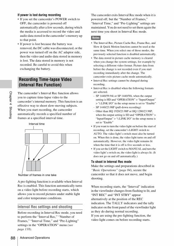
88
Chapter 4 S
hooting
If power is lost during recording• If you set the camcorder’s POWER switch to
OFF, the camcorder is powered off automatically after a few seconds, during which the media is accessed to record the video and audio data stored in the camcorder’s memory up to that point.
• If power is lost because the battery was removed, the DC cable was disconnected, or the power was turned off on the AC adaptor side, then the video and audio data stored in memory is lost. The data stored in memory is not recorded. Be careful to avoid this when exchanging the battery.
The camcorder’s Interval Rec function allows you to capture time-lapse video to the camcorder’s internal memory. This function is an effective way to shoot slow-moving subjects.When you start recording, the camcorder automatically records a specified number of frames at a specified interval time.
A pre-lighting function is available when Interval Rec is enabled. This function automatically turns on a video light before recording starts, which allows you to record pictures under stable light and color temperature conditions.
Interval Rec settings and shootingBefore recording in Interval Rec mode, you need to perform the “Interval Rec,” “Number of Frames,” “Interval Time,” and “Pre-Lighting” settings in the “OPERATION” menu (see page 118).
The camcorder exits Interval Rec mode when it is powered off, but the “Number of Frames,” “Interval Time,” and “Pre-Lighting” settings are maintained. You do not need to set them again the next time you shoot in Interval Rec mode.
Notes
• The Interval Rec, Picture Cache Rec, Frame Rec, and Slow & Quick Motion function cannot be used at the same time. When you select one of those modes, the previously selected function is disabled automatically.
• The data stored in picture cache memory is cleared when you change the system settings, for example by selecting a different video format. Picture data from before the change is not recorded even if you start recording immediately after the change. The camcorder exits picture cache mode automatically.
• Interval Rec settings cannot be changed during recording.
• Interval Rec is disabled when the following formats are selected.- SP 1440/59.94i or SP 1440/50i, when the output
setting is HD and “OPERATION” > “Input/Output” > “i.LINK I/O” in the setup menu is set to “Enable”
- SP 1440/23.98P (pull-down recording)- Other than HQ 1920/23.98P or HQ 1280/23.98P,
when the output setting is SD and “OPERATION” > “Input/Output” > “i.LINK I/O” in the setup menu is set to “Enable”
• If you want to turn the video light on before the start of recording, set the camcorder’s LIGHT switch to AUTO. The video light’s switch must also be turned on. When this is done, the video light turns on and off automatically. However, the video light remains lit when the time that it is off is five seconds or less.
• If you set the LIGHT switch to MANUAL and turn the video light’s switch on, the video light is always lit. (It does not go on and off automatically.)
To shoot in Interval Rec modeMake the settings and preparations described in “Basic Operations” (page 84), secure the camcorder so that it does not move, and begin shooting.
When recording starts, the “Interval” indication in the viewfinder changes from flashing to lit, and “INT REC” and “INT STBY” appear alternatively at the position of the REC indication. The TALLY indicators and the tally indicator on the front panel of the viewfinder light as they do during normal recording.If you are using the pre-lighting function, the video light comes on before recording starts.
Recording Time-lapse Video (Interval Rec Function)
Interval time
Number of frames in one take
Advanced Operations
Chapter 4 S
hooting
Limitations during recording• The i.LINK (HDV/DV) connector cannot be
used.• Regardless of the setting of the F-RUN/SET/
R-RUN switch, the advance mode of the internal timecode generator is always R-RUN.
• Audio cannot be recorded.• Recording review is not possible.• If you press the SLOT SELECT button, the
camcorder completes recording of the specified number of frames, creates a clip, and switches to the other media.
• Genlock is not possible.
If power is lost during recording• If you set the camcorder’s POWER switch to
OFF, the camcorder is powered off automatically after a few seconds, during which the media is accessed to record the video and audio data stored in the camcorder’s memory up to that point.
• If power is lost because the battery was removed, the DC cable was disconnected, or the power was turned off on the AC adaptor side, then the video and audio data shot up to that point may be lost (maximum 15 seconds). Be careful to avoid this when exchanging the battery.
The Frame Rec function is useful for shooting stop motion animations, such as animations with puppets or clay figures.Each time that you press the recording start button, the camcorder shoots a specified number of frames and then stops.
Frame Rec settings and shootingBefore recording in Frame Rec mode, you need to perform the “Frame Rec” and “Number of Frames” settings in the “OPERATION” menu (see page 118).The camcorder exits Frame Rec mode when it is powered off, but the setting for the number of frames setting is maintained. You do not need to set it again the next time you shoot in Frame Rec mode.
Notes
• The Interval Rec, Picture Cache Rec, Frame Rec, and Slow & Quick Motion function cannot be used at the same time. When you select one of those modes, the previously selected function is disabled automatically.
• The data stored in memory is cleared when you change the system settings, for example by selecting a different video format. Picture data from before the change is not recorded even if you start recording immediately after the change. The camcorder exits Frame Rec mode automatically.
• Frame Rec settings cannot be changed during recording.
• Frame Rec is disabled when the following formats are selected.- SP 1440/59.94i or SP 1440/50i, when the output
setting is HD and “OPERATION” > “Input/Output” > “i.LINK I/O” in the setup menu is set to “Enable”
- SP 1440/23.98P (pull-down recording)- Other than HQ 1920/23.98P or HQ 1280/23.98P,
when the output setting is SD and “OPERATION” > “Input/Output” > “i.LINK I/O” in the setup menu is set to “Enable”
To shoot in Frame Rec modeMake the settings and preparations described in “Basic Operations” (page 84), secure the camcorder so that it does not move, and begin shooting.
When recording starts, the “Frame Rec” indication in the viewfinder changes from flashing to lit, and “FRM REC” and “FRM STBY” appear alternatively at the position of the REC indication. The TALLY indicators and the tally indicator on the front panel of the viewfinder light as they do during normal recording.
Limitations during recording• The i.LINK (HDV/DV) connector cannot be
used.• Regardless of the setting of the F-RUN/SET/
R-RUN switch, the advance mode of the internal timecode generator is always R-RUN.
• Audio cannot be recorded.• Recording review is not possible.• If you press the SLOT SELECT button, the
camcorder completes recording of the specified number of frames, creates a clip, and switches to the other media.
• Genlock is not possible.
If power is lost during recording• If you set the camcorder’s POWER switch to
OFF, the camcorder is powered off automatically after a few seconds, during which
Shooting Stop Motion Animations (Frame Rec Function)
Advanced Operations 89
90
Chapter 4 S
hooting
the media is accessed to record the video and audio data stored in the camcorder’s memory up to that point.
• If power is lost because the battery was removed, the DC cable was disconnected, or the power was turned off on the AC adaptor side, then the video and audio data shot up to that point may be lost (maximum 15 seconds). Be careful to avoid this when exchanging the battery.
When the camcorder is in HD mode and the video format (see page 44) is set to one of the formats listed below, you can specify a recording frame rate that is different from the playback frame rate.When the “Country” setting is “NTSC Area”/
”NTSC(J) Area”
When the “Country” setting is “PAL Area”
Slow & Quick Motion settings and shootingBefore recording in Slow & Quick Motion mode, you need to perform the “Slow & Quick” and “Frame Rate” settings in the “OPERATION” menu (see page 117).When you finish making these settings, the system frequency and the frame rate appear at the top of the viewfinder screen. You can change the frame rate while viewing the display in the viewfinder by turning the MENU knob.The Slow & Quick Motion mode setting and the frame rate are retained even after the camcorder is powered off.
Notes
• The Interval Rec, Picture Cache Rec, Frame Rec, and Slow & Quick Motion function cannot be used at the same time. When you select one of those modes, the previously selected function is disabled automatically.
• Slow & Quick Motion is disabled when the slow shutter function (viewfinder display “SLS”) function is enabled. The slow shutter function is disabled when the Slow & Quick Motion function is enabled.
• Slow & Quick Motion is disabled when “OPERATION” > “Input/Output” > “i.LINK I/O” in the setup menu is set to “Enable.” When Slow & Quick Motion is enabled, “i.LINK I/O” is fixed as “Disable.”
• Slow & Quick Motion settings cannot be changed during recording.
To shoot in Slow & Quick Motion modeShoot as described in “Basic Operations” (page 84).
When recording starts, the “S&Q STBY” indication in the viewfinder changes to the “zS&Q REC” indication. The TALLY indicators and the tally indicator on the front
Shooting with Slow & Quick Motion
Recording format System frequencyXAVC-I 1920/29.97P
1920/23.98P1280/59.94P
XAVC-L50 1920/29.97P1920/23.98P1280/59.94P
XAVC-L35 1920/29.97P1920/23.98P
HD422 50/1920/29.97P50/1920/23.98P50/1280/59.94P50/1280/29.97P50/1280/23.98P
HQ 1920/29.97P1920/23.98P1280/59.94P1280/29.97P1280/23.98P
Recording format System frequencyXAVC-I 1920/25P
1280/50P
XAVC-L50 1920/25P1280/50P
XAVC-L35 1920/25P
HD422 50/1920/25P50/1280/50P50/1280/25P
HQ 1920/25P1280/50P1280/25P
Advanced Operations
Chapter 4 S
hooting
panel of the viewfinder light as they do during normal recording.
Limitations during recording• The i.LINK (HDV/DV) connector cannot be
used.• Regardless of the setting of the F-RUN/SET/
R-RUN switch, the advance mode of the internal timecode generator is always R-RUN.
• Audio cannot be recorded when the recording and playback frame rates differ.
• Recording review is not possible.• If you change the recording frame rate to a value
faster than the current shutter speed, the shutter speed is changed to the slowest value for which shooting is possible.Example: If the frame rate is 32 and the shutter speed is 1/40, and you change the frame rate to 55, then the shutter speed is changed to 1/60.If is not possible to select a shutter speed that is slower than the recording frame rate.
• Genlock is not possible.
Normally, a clip is created as an independent file each time that you start and stop recording. But this function allows you to start and stop recording while continuously recording to the same clip, for as long as the function remains enabled. This is convenient when you do not want to generate a large number of short clips, and when you want to record without worrying about exceeding the clip limit. It is still easy to find recording start points, because a Rec Start essence mark is recorded at the recording start point each time you start recording.
Clip Continuous Rec settings and shooting
Notes
• The Clip Continuous Rec function cannot be used at the same time as the Picture Cache, Interval Rec, Frame Rec, or Slow & Quick Motion function. When you select Clip Continuous Rec mode, the Picture Cache, Interval Rec, Frame Rec, and Slow & Quick Motion functions are disabled. When you select picture cache, Frame Rec, Interval Rec, or Slow & Quick Motion mode, the Clip Continuous Rec function is disabled.
• The Clip Continuous Rec function is disabled when the recording mode is FAT.
To make Clip Continuous Rec settings
1 Select “OPERATION” > “Rec Function” > “Clip Continuous Rec” in the setup menu.
See “Basic Setup Menu Operations” (page 110) for more information about menu operations.
2 Turn the MENU knob to select “On,” and then press the knob.The “CONT” indication flashes in the viewfinder, and the function is enabled.
You can assign the Clip Continuous Rec on/off function to one of the ASSIGN 1/2/3 switches, ASSIGNABLE 4/5 switches, and the COLOR TEMP button.
For details, see “Assigning Functions to Assignable Switches” (page 158).
To shoot in Clip Continuous Rec modeShoot as described in “Basic Operations” (page 84).When recording starts, the “CONT” indication in the viewfinder changes to “zREC” indication. The TALLY indicators and the tally indicator on the front panel of the viewfinder light as they do during normal recording.
Note
During recording or in recording standby mode (when the “CONT” indication is lit), if you remove the media, the battery, or the power source, the media needs to be restored. It is not possible to restore media on a device other than this camcorder.Exit Clip Continuous Rec mode (see page 92) and then remove the media.When the “CONT” indication is flashing (at 1 flash/s), you can remove the media.
To stop shootingStop the recording.The camcorder changes to the recording standby mode (STBY) and the “CONT” indication lights up.
Note
Stop the recording after the recording continues for two or more seconds.
Recording with the Clip Continuous Rec Function
Advanced Operations 91
92
Chapter 4 S
hooting
To exit Clip Continuous Rec modeWith the camcorder in recording standby mode, set “OPERATION” > “Rec Function” > “Clip Continuous Rec” in the setup menu to “Off.”
Limitations during recordingA single continuous clip cannot be created if you perform one of the following operations while the camcorder is in recording or recording standby mode (A new clip will be created when you next start recording.)• Operate on a clip (lock, delete, or rename a clip)• Change the slot• Change the recording format• Turn off the POWER switch• Playback• Switched to thumbnail mode
The freeze mix function allows you to temporarily overlap a still image (freeze picture) from a clip shot in HD mode onto the current camera picture. This makes it easier to frame the shot.
Note
The freeze mix function is not available in the following cases.• When the recording format is SP 1440/23.98P• When the video formats of the recorded picture and the
camera picture differ• When you are shooting in Slow & Quick Motion mode
or slow shutter mode• When there is i.LINK input
To display a freeze mix picture
1 Play a clip or conduct a recording review of a clip with the same format as the camera picture.
2 Display the picture that you want to use as the frame, and then turn on the assignable switch to which the Freeze Mix function has been assigned.The recording review picture is frozen and overlaps the camera picture.
Note
The following functions are disabled at the freeze mix times.
• Menu operations• During Focus Mag display• Marker display• Zebra display• Peaking display• Skin details display
To cancel the freeze mix displayDo one of the following.• Press an assignable switch again to which the
Freeze Mix function has been assigned.The freeze mix display is canceled and the display returns to the normal camera picture.
• Start recording (see page 84).Normal recording starts.
Framing Shots with the Freeze Mix Function
Advanced Operations
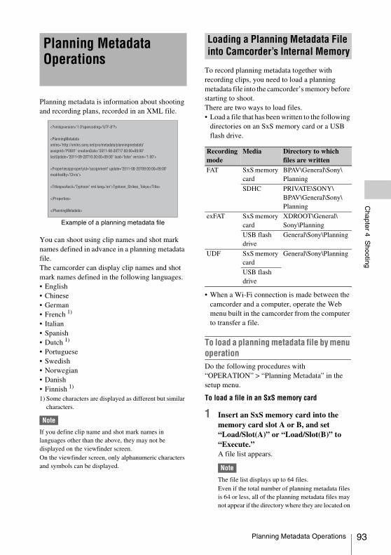
Chapter 4 S
hooting
Planning metadata is information about shooting and recording plans, recorded in an XML file.
Example of a planning metadata file
You can shoot using clip names and shot mark names defined in advance in a planning metadata file. The camcorder can display clip names and shot mark names defined in the following languages.• English• Chinese• German• French 1)
• Italian• Spanish• Dutch 1)
• Portuguese • Swedish• Norwegian• Danish• Finnish 1)
1) Some characters are displayed as different but similar characters.
Note
If you define clip name and shot mark names in languages other than the above, they may not be displayed on the viewfinder screen.On the viewfinder screen, only alphanumeric characters and symbols can be displayed.
To record planning metadata together with recording clips, you need to load a planning metadata file into the camcorder’s memory before starting to shoot.There are two ways to load files.• Load a file that has been written to the following
directories on an SxS memory card or a USB flash drive.
• When a Wi-Fi connection is made between the camcorder and a computer, operate the Web menu built in the camcorder from the computer to transfer a file.
To load a planning metadata file by menu operationDo the following procedures with “OPERATION” > “Planning Metadata” in the setup menu.
To load a file in an SxS memory card
1 Insert an SxS memory card into the memory card slot A or B, and set “Load/Slot(A)” or “Load/Slot(B)” to “Execute.”A file list appears.
Note
The file list displays up to 64 files.Even if the total number of planning metadata files is 64 or less, all of the planning metadata files may not appear if the directory where they are located on
Planning Metadata Operations
Loading a Planning Metadata File into Camcorder’s Internal Memory
Recording mode
Media Directory to which files are written
FAT SxS memory card
BPAV\General\Sony\Planning
SDHC PRIVATE\SONY\BPAV\General\Sony\Planning
exFAT SxS memory card
XDROOT\General\Sony\Planning
USB flash drive
General\Sony\Planning
UDF SxS memory card
General\Sony\Planning
USB flash drive
Planning Metadata Operations 93
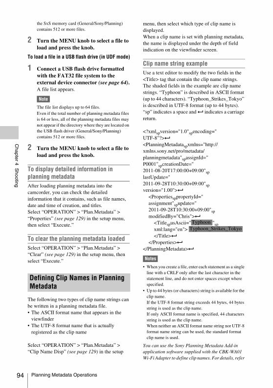
94
Chapter 4 S
hooting
the SxS memory card (General/Sony/Planning) contains 512 or more files.
2 Turn the MENU knob to select a file to load and press the knob.
To load a file in a USB flash drive (in UDF mode)
1 Connect a USB flash drive formatted with the FAT32 file system to the external device connector (see page 64).A file list appears.
Note
The file list displays up to 64 files.Even if the total number of planning metadata files is 64 or less, all of the planning metadata files may not appear if the directory where they are located on the USB flash driver (General/Sony/Planning) contains 512 or more files.
2 Turn the MENU knob to select a file to load and press the knob.
To display detailed information in planning metadataAfter loading planning metadata into the camcorder, you can check the detailed information that it contains, such as file names, date and time of creation, and titles.Select “OPERATION” > “Plan.Metadata” > “Properties” (see page 129) in the setup menu, then select “Execute.”
To clear the planning metadata loadedSelect “OPERATION” > “Plan.Metadata” > “Clear” (see page 129) in the setup menu, then select “Execute.”
The following two types of clip name strings can be written in a planning metadata file.• The ASCII format name that appears in the
viewfinder • The UTF-8 format name that is actually
registered as the clip name
Select “OPERATION” > “Plan.Metadata” > “Clip Name Disp” (see page 129) in the setup
menu, then select which type of clip name is displayed.When a clip name is set with planning metadata, the name is displayed under the depth of field indication on the viewfinder screen.
Clip name string exampleUse a text editor to modify the two fields in the <Title> tag that contain the clip name strings.The shaded fields in the example are clip name strings. “Typhoon” is described in ASCII format (up to 44 characters). “Typhoon_Strikes_Tokyo” is described in UTF-8 format (up to 44 bytes).“sp” indicates a space and 3 indicates a carriage return.
<?xmlspversion="1.0"spencoding="UTF-8"?>3
<PlanningMetadataspxmlns="http://xmlns.sony.net/pro/metadata/planningmetadata"spassignId="P0001"spcreationDate="2011-08-20T17:00:00+09:00"splastUpdate="2011-09-28T10:30:00+09:00"spversion="1.00">3
<PropertiessppropertyId="assignment"spupdate="2011-09-28T10:30:00+09:00"spmodifiedBy="Chris">3
<TitlespusAscii=" "spxml:lang="en"> </Title>3
</Properties>3
</PlanningMetadata>3
Notes
• When you create a file, enter each statement as a single line with a CRLF only after the last character in the statement line, and do not enter spaces except where specified.
• Up to 44 bytes (or characters) string is available for the clip name.If the UTF-8 format string exceeds 44 bytes, 44 bytes string is used as the clip name.If only ASCII format name is specified, 44 characters string is used as the clip name.When neither an ASCII format name string nor UTF-8 format name string can be used, the standard format clip name is used.
You can use the Sony Planning Metadata Add-in application software supplied with the CBK-WA01 Wi-Fi Adapter to define clip names. For details, refer
Defining Clip Names in Planning Metadata
TyphoonTyphoon_Strikes_Tokyo
Planning Metadata Operations
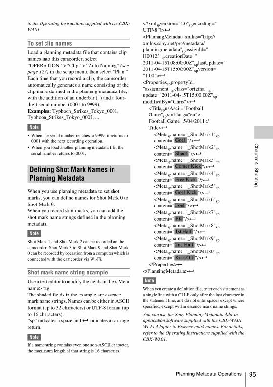
Chapter 4 S
hooting
to the Operating Instructions supplied with the CBK-WA01.To set clip namesLoad a planning metadata file that contains clip names into this camcorder, select “OPERATION” > “Clip” > “Auto Naming” (see page 127) in the setup menu, then select “Plan.”Each time that you record a clip, the camcorder automatically generates a name consisting of the clip name defined in the planning metadata file, with the addition of an underbar (_) and a four-digit serial number (0001 to 9999).Examples: Typhoon_Strikes_Tokyo_0001, Typhoon_Strikes_Tokyo_0002, ...
Note
• When the serial number reaches to 9999, it returns to 0001 with the next recording operation.
• When you load another planning metadata file, the serial number returns to 0001.
When you use planning metadata to set shot marks, you can define names for Shot Mark 0 to Shot Mark 9.When you record shot marks, you can add the shot mark name strings defined in the planning metadata.
Note
Shot Mark 1 and Shot Mark 2 can be recorded on the camcorder. Shot Mark 3 to Shot Mark 9 and Shot Mark 0 can be recorded by operation from a computer which is connected with the camcorder via Wi-Fi.
Shot mark name string exampleUse a text editor to modify the fields in the < Meta name> tag.The shaded fields in the example are essence mark name strings. Names can be either in ASCII format (up to 32 characters) or UTF-8 format (up to 16 characters). “sp” indicates a space and 3 indicates a carriage return.
Note
If a name string contains even one non-ASCII character, the maximum length of that string is 16 characters.
<?xmlspversion="1.0"spencoding="UTF-8"?>3
<PlanningMetadata xmlns="http://xmlns.sony.net/pro/metadata/planningmetadata"spassignId="H00123"spcreationDate="2011-04-15T08:00:00Z"splastUpdate="2011-04-15T15:00:00Z"spversion="1.00">3
<PropertiessppropertyId="assignment"spclass="original"spupdate="2011-04-15T15:00:00Z"spmodifiedBy="Chris">3
<TitlespusAscii="FootballGame"spxml:lang="en">Football Game 15/04/2011</Title>3
<Metaspname="_ShotMark1"spcontent=" "/>3
<Metaspname="_ShotMark2"spcontent=" "/>3
<Metaspname="_ShotMark3"spcontent=" "/>3
<Metaspname="_ShotMark4"spcontent=" "/>3
<Metaspname="_ShotMark5"spcontent=" "/>3
<Metaspname="_ShotMark6"spcontent=" "/>3
<Metaspname="_ShotMark7"spcontent=" "/>3
<Metaspname="_ShotMark8"spcontent=" "/>3
<Metaspname="_ShotMark9"spcontent=" "/>3
<Metaspname="_ShotMark0"spcontent=" "/>3
</Properties>3
</PlanningMetadata>3
Note
When you create a definition file, enter each statement as a single line with a CRLF only after the last character in the statement line, and do not enter spaces except where specified, except within essence mark name strings.
You can use the Sony Planning Metadata Add-in application software supplied with the CBK-WA01 Wi-Fi Adapter to Essence mark names. For details, refer to the Operating Instructions supplied with the CBK-WA01.
Defining Shot Mark Names in Planning Metadata
Goal
Shoot
Corner Kick
Free Kick
Goal Kick
Foul
PK
1st Half
2nd Half
Kick Off
Planning Metadata Operations 95
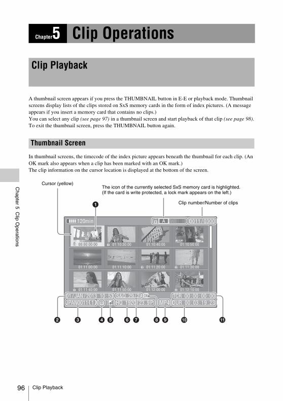
96
Chapter 5 C
lip Operations
A thumbnail screen appears if you press the THUMBNAIL button in E-E or playback mode. Thumbnail screens display lists of the clips stored on SxS memory cards in the form of index pictures. (A message appears if you insert a memory card that contains no clips.)You can select any clip (see page 97) in a thumbnail screen and start playback of that clip (see page 98).To exit the thumbnail screen, press the THUMBNAIL button again.
In thumbnail screens, the timecode of the index picture appears beneath the thumbnail for each clip. (An OK mark also appears when a clip has been marked with an OK mark.)The clip information on the cursor location is displayed at the bottom of the screen.
Chapter5 Clip Operations
Clip Playback
Thumbnail Screen
Clip number/Number of clips
Cursor (yellow)The icon of the currently selected SxS memory card is highlighted.(If the card is write protected, a lock mark appears on the left.)
Clip Playback
Chapter 5 C
lip Operations
a Index pictureUDF, exFAT, FAT-HD mode: When a clip is recorded, its first frame is set automatically as the index picture. You can change the index picture to any frame (see page 107). If the clip is locked or the OK mark is on the clip, the lock mark appears.FAT-SD mode: When a clip is recorded, its first frame is set automatically as the index picture. If the file size is larger than 2 GB, and that the clip has been split before being saved, the take mark
appears.You can check the segment files on the expand thumbnail screen (see page 105).
b Date and start time of recording
c Clip nameThe number after the clip name (delimited by /) is the number of components. This appears only for clips larger than 2 GB in size, which have been split into smaller files for storage in the FAT-SD mode.
d Lock mark (UDF, exFAT, and FAT-HD mode only)
Indicates the selected clip is marked with an OK mark.
e Independent AV file icon (UDF, exFAT, and FAT-HD mode only)
Appears only when a clip is an independent AV file. SxS memory cards may contain independent files that have been added directly from a computer. Because independent files lack the associated management files, some operations and information displays may not be available.
f Video format of recording
g Special recording information (UDF, exFAT, and FAT-HD mode only)
Displays the mode of clips that have been recorded in a special mode (Slow & Quick Motion, Interval Rec, Frame Rec).For Slow & Quick Motion clips, the frame rates are displayed to the right as “Recording frame rate/Playback frame rate” fps.
h OK, NG, KP mark (UDF, exFAT, and FAT-HD mode only)
UDF, exFAT: When an OK, NG, or KP flag is added to the selected clip, the corresponding mark is added to the clip.
FAT-HD mode: When an OK mark is added to the selected clip, the OK mark is added to the clip.
i File formatIndicates the file format of the selected clip (MXF, MP4. AVI). (File format does not indicate when in UDF/HD mode.)
j Clip duration
k TimecodeThis is the timecode of the index picture.
Note
Normal thumbnail screens display SD clips only or HD clips only, even if the SxS memory card contains clips in both formats. You can select the format to display by selecting a mode with “OPERATION” > “Format” > “HD/SD” (see page 113) in the setup menu.If you want to display all recorded clips, regardless of the HD/SD mode, switch to the all clips thumbnail screen. However, it is not possible to start playback from the all clips thumbnail screen (see page 102).
To switch between SxS memory cardsWhen two SxS memory cards are loaded, you can switch between them by pressing the SLOT SELECT button.
Note
While an expand thumbnail screen (see page 98) or a shot mark (essence mark) thumbnail screen (see page 106) is displayed, SxS memory cards cannot be switched.
To select clip thumbnailsDo one of the following to move the yellow cursor to the clip that you want to select.• Press an arrow button (J, j, K, k).• Turn the MENU knob.• Press the PREV or NEXT button.
To select the first thumbnailWith the F REV button held down, press the PREV button.
To select the last thumbnailWith the F FWD button held down, press the NEXT button.
Playing Clips
Clip Playback 97
98
Chapter 5 C
lip Operations
To play clips sequentially starting from a selected clip
1 Select the thumbnail of the clip that you want to play first.
2 Press the PLAY/PAUSE button.Play begins from the top of the selected clip.
Play continues through all clips after the selected clip.When the last clip has been played to the end, the camcorder enters pause (still image) mode at the last frame of the last clip.Press the THUMBNAIL button to return to the thumbnail screen.Playback also stops if you eject the memory card. In this case, the camera picture appears in the viewfinder.
Notes
• There may be momentary picture breakup or still image display at the transition from one clip to another. During this time, the playback controls and the THUMBNAIL button cannot be operated.
• When you select a clip in the thumbnail screen and begin playback, there may be momentary picture breakup at the top of the clip. To view the top of the clip without breakup, put the camcorder into playback mode, pause, use the PREV button to return to the top of the clip, and start playback again.
• On SxS memory cards that contain both HD-mode and SD-mode clips, you cannot play all clips in sequence. For example, while an HD mode thumbnail screen is displayed, only HD mode clips are played in sequence.
To cue up clips
To play from the top of the first clipSimultaneously press the PREV and F REV buttons. This jumps to the top of the first clip on the SxS memory card.
To play from the top of the last clipSimultaneously press the NEXT and F FWD buttons. This jumps to the top of the last clip on the SxS memory card.
To add a shot mark during play (HD mode only)You can add shot marks to clips during play by using the same method used during recording (see page 86).
Notes
• Shot marks cannot be recorded when the SxS memory card is write protected.
• Shot marks cannot be added at the first frame of each clip or last frame of the last clip.
• Expand thumbnail screen• Shot mark thumbnail screen (HD mode only)
Like the normal thumbnail screen and the OK clip thumbnail screen, these screens allow you to select clip thumbnails (see page 97) and to start clip playback (see page 98).
To search for scenes in clips with the expand thumbnail screenTo display the expand thumbnail screen, select a clip in the thumbnail screen and press the EXPAND button (see page 17) or select “THUMBNAIL” > “Thumbnail View” > “Forward Expansion” in the setup menu. The selected clip is displayed as follows.HD mode: The clip is divided into 12 equally-
sized blocks, and a thumbnail of the first frame in each block is displayed.
SD mode: Only in the case of clips that have been split into partial files because the file size was larger than 2 GB, a thumbnail of the first frame of each partial file is displayed.
See “Displaying the Expand Thumbnail Screen (UDF/exFAT/FAT-HD Mode only)” (page 105) for more information about the expand thumbnail screen.
Using Thumbnails to Search Inside Clips
Clip Playback
Chapter 5 C
lip Operations
To search for shot marks in clips with the shot mark thumbnail screen (HD mode only)When a clip contains one or more shot marks, you can easily find them with the shot mark thumbnail screen. The shot mark thumbnail screen displays a thumbnail of each shot mark frame in the clip.To display the shot mark thumbnail screen, press the ESSENCE MARK button (see page 18) or select “THUMBNAIL” > “Thumbnail View” > “Essence Mark Thumbnail” in the setup menu.
See “Displaying the Shot Mark Thumbnail Screen (UDF/exFAT/FAT-HD Mode Only)” (page 106) for more information about the shot mark thumbnail screen.
Clip Playback 99
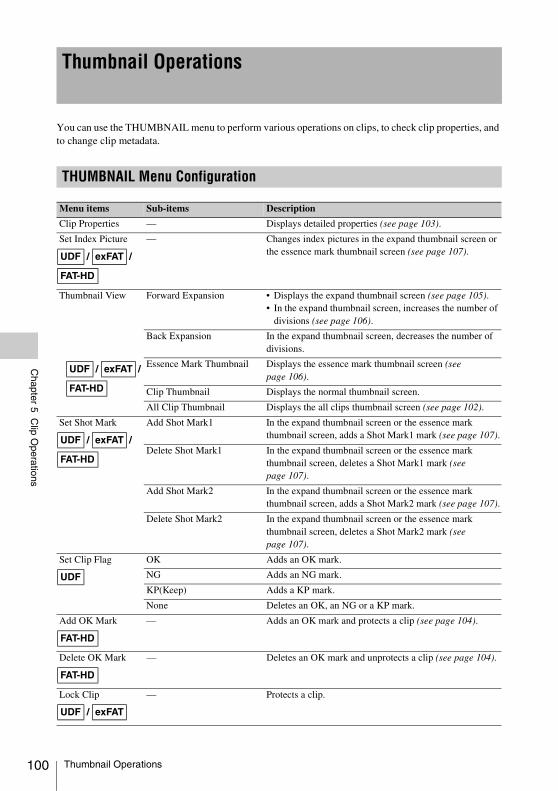
100
Chapter 5 C
lip Operations
You can use the THUMBNAIL menu to perform various operations on clips, to check clip properties, and to change clip metadata.
Thumbnail Operations
THUMBNAIL Menu Configuration
Menu items Sub-items Description
Clip Properties — Displays detailed properties (see page 103).
Set Index Picture — Changes index pictures in the expand thumbnail screen or the essence mark thumbnail screen (see page 107).
Thumbnail View Forward Expansion • Displays the expand thumbnail screen (see page 105).• In the expand thumbnail screen, increases the number of
divisions (see page 106).
Back Expansion In the expand thumbnail screen, decreases the number of divisions.
Essence Mark Thumbnail Displays the essence mark thumbnail screen (see page 106).
Clip Thumbnail Displays the normal thumbnail screen.
All Clip Thumbnail Displays the all clips thumbnail screen (see page 102).
Set Shot Mark Add Shot Mark1 In the expand thumbnail screen or the essence mark thumbnail screen, adds a Shot Mark1 mark (see page 107).
Delete Shot Mark1 In the expand thumbnail screen or the essence mark thumbnail screen, deletes a Shot Mark1 mark (see page 107).
Add Shot Mark2 In the expand thumbnail screen or the essence mark thumbnail screen, adds a Shot Mark2 mark (see page 107).
Delete Shot Mark2 In the expand thumbnail screen or the essence mark thumbnail screen, deletes a Shot Mark2 mark (see page 107).
Set Clip Flag OK Adds an OK mark.
NG Adds an NG mark.
KP(Keep) Adds a KP mark.
None Deletes an OK, an NG or a KP mark.
Add OK Mark — Adds an OK mark and protects a clip (see page 104).
Delete OK Mark — Deletes an OK mark and unprotects a clip (see page 104).
Lock Clip — Protects a clip.
UDF / exFAT /
FAT-HD
UDF / exFAT /
FAT-HD
UDF / exFAT /
FAT-HD
UDF
FAT-HD
FAT-HD
UDF / exFAT
Thumbnail Operations
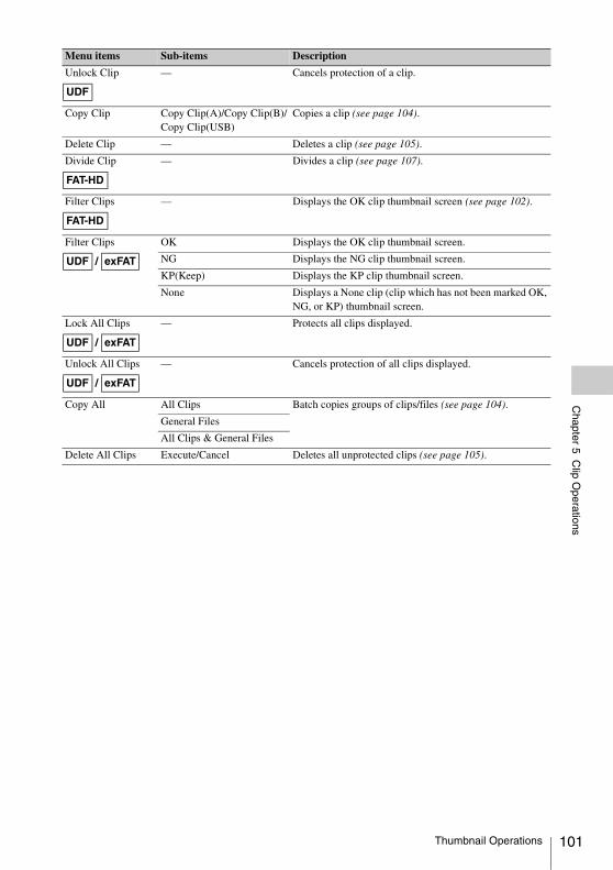
Chapter 5 C
lip Operations
Unlock Clip — Cancels protection of a clip.
Copy Clip Copy Clip(A)/Copy Clip(B)/Copy Clip(USB)
Copies a clip (see page 104).
Delete Clip — Deletes a clip (see page 105).
Divide Clip — Divides a clip (see page 107).
Filter Clips — Displays the OK clip thumbnail screen (see page 102).
Filter Clips OK Displays the OK clip thumbnail screen.
NG Displays the NG clip thumbnail screen.
KP(Keep) Displays the KP clip thumbnail screen.
None Displays a None clip (clip which has not been marked OK, NG, or KP) thumbnail screen.
Lock All Clips — Protects all clips displayed.
Unlock All Clips — Cancels protection of all clips displayed.
Copy All All Clips Batch copies groups of clips/files (see page 104).
General Files
All Clips & General Files
Delete All Clips Execute/Cancel Deletes all unprotected clips (see page 105).
Menu items Sub-items Description
UDF
FAT-HD
FAT-HD
UDF / exFAT
UDF / exFAT
UDF / exFAT
Thumbnail Operations 101
102
Chapter 5 C
lip Operations
See “Basic Setup Menu Operations” (page 110) for information about menu operations.
To display the THUMBNAIL menu
1 Press the THUMBNAIL button to display the thumbnail screen.
2 Set the MENU ON/OFF switch to ON, or press the MENU button.
3 Turn the MENU knob to select “TH,” and then press the knob. Or press the J or j button to select “TH,” and then press the SET button.The THUMBNAIL menu appears.
To hide the THUMBNAIL menu, press the MENU button again.
To select menu items and sub-itemsDo one of the following.• Turn the MENU knob to select an item or sub-
item, and then press the knob.• Press the arrow buttons (J, j, K, k) to
select an item or sub-item, and then press the SET button.
According to the selected item or sub-item, a selection list or a clip properties screen appears (see page 103).To return to the previous state, push the MENU CANCEL/PRST/ESCAPE switch down to the ESCAPE side.
Notes
• Some items cannot be operated, when an SxS memory card is write protected.
• Some items cannot be selected, depending on the state of the camcorder when the menu was displayed.
To hide the clip properties screenDo one of the following.Press the RESET/RETURN button: This
returns to the THUMBNAIL menu.Press the THUMBNAIL button: The
camcorder enters E-E mode, and the camera picture appears.
Press the PLAY/PAUSE button: Playback from the selected clip starts.
To display OK clip thumbnails (HD mode only)When the normal thumbnail screen is displayed, you can select “THUMBNAIL” > “Filter Clips” to switch to the OK clip thumbnail screen.
See “Adding/Deleting the OK Mark (FAT-HD Mode Only)” (page 104) for information about how to add OK marks.
OK/NG/KP/None-Clip thumbnail screenOnly the clips flagged OK/NG/KP—or clips with no flag (“None”)—among the clips on the current SxS memory card are displayed.You can select the type of flag to display with “THUMBNAIL” > “Filter Clips” (see page 101).
To display the all clips thumbnail screenWhen the normal thumbnail screen is displayed, you can switch to the all clips thumbnail screen by selecting “THUMBNAIL” > “All Clip Thumbnail.”
Pressing the RESET/RETURN button returns you to the normal thumbnails screen, where you can perform playback and other clip operations.
Note
You cannot start playback from the all clips thumbnail screen.
Basic THUMBNAIL Menu Operations
Changing the Thumbnail Screen Type
Thumbnail Operations
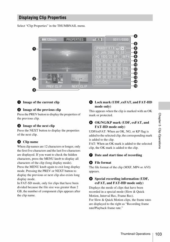
Chapter 5 C
lip Operations
Select “Clip Properties” in the THUMBNAIL menu.
a Image of the current clip
b Image of the previous clipPress the PREV button to display the properties of the previous clip.
c Image of the next clipPress the NEXT button to display the properties of the next clip.
d Clip nameWhen clip names are 12 characters or longer, only the first five characters and the last five characters are displayed. If you want to check the hidden characters, press the MENU knob to display all characters of the clip (long display mode).Press the MENU knob again to exit long display mode. Pressing the PREV or NEXT button to display the previous or next clip also exists long display mode.In FAT-SD mode, only for clips that have been divided because the file size was greater than 2 GB, the number of component clips appears after the clip name.
e Lock mark (UDF, exFAT, and FAT-HD mode only)
This appears when the clip is marked with an OK mark or protected.
f OK/NG/KP mark (UDF, exFAT, and FAT-HD mode only)
UDF/exFAT: When an OK, NG, or KP flag is added to the selected clip, the corresponding mark is added to the clip.FAT: When an OK mark is added to the selected clip, the OK mark is added to the clip.
g Date and start time of recording
h File formatThe file format of the clip (MXF, MP4 or AVI) appears.
i Special recording information (UDF, exFAT, and FAT-HD mode only)
Displays the mode of clips that have been recorded in a special mode (Slow & Quick Motion, Interval Rec, Frame Rec).For Slow & Quick Motion clips, the frame rates are displayed to the right as “Recording frame rate/Playback frame rate.”
Displaying Clip Properties
Thumbnail Operations 103
104
Chapter 5 C
lip Operations
j Timecode of the displayed image
k Timecode of the recording start point
l Timecode of the recording end point
m Duration
n Recorded audio channels
o Video format of recording
You can add an OK/NG/KP flag to clips recorded in UDF. By adding flags, you can set the camcorder to display only clips with certain flag settings on the thumbnail screen (OK/NG/KP/None-Clip thumbnail screen) (see page 102).When adding a flag, you can select from “OK,” “NG,” “KP” (Keep) in “Set Clip Flag” of the THUMBNAIL menu (see page 100) on the thumbnail screen. When deleting a flag, select “None.”
Note
Flagged clips are not protected. To protect clips from deletion, select “Lock Clip” in the THUMBNAIL menu (see page 100) on the thumbnail screen. To remove the protection, select “Unlock Clip.”
By adding an OK mark to clips recorded in FAT-HD Mode, you can set the camcorder to display only the necessary clips on the thumbnail screen (see page 102). Clips with an OK mark added are blocked from being deleted or segmented. To delete or segment them, remove the OK mark. From the THUMBNAIL menu (see page 102) on the thumbnail screen, you can select “Add OK Mark” to add an OK mark, or “Delete OK Mark” to delete the OK mark.
You can copy clips to other SxS memory cards.Clips are copied to destination SxS memory cards using the same names as the original clips.
Notes
• If a clip with the same name already exists at the copy destination SxS memory card, a one-digit number in parentheses is added to the original name.The number in parentheses is the smallest number that does not exist at the copy destination.
Examples:ABCD0002tABCD0002(1)ABCD0002(1)tABCD0002(2)ABCD0005(3)tABCD0005(4)
• If the parenthetical numbers (1) to (9) already exist at the copy destination, it is not possible to copy any more clips under that name. (A tenth clip cannot be copied.)
• A message appears if there is not enough free capacity at the copy destination SxS memory card. Exchange the card for one with more free capacity.
• When multiple clips are recorded in a source SxS memory card, it may not be possible to copy all clips to the end. Depending on memory characteristics and usage of the memory cards, this can occur even when the source and destination memory cards have the same capacity.
Copying a specified clipYou can copy a clip selected on the thumbnail screen to another SxS memory card.Select “THUMBNAIL” > “Copy Clip” > “Execute” in the setup menu, then press the MENU knob.
To cancel a copy operationPress the RESET/RETURN button.
To batch copy groups of clips/filesSelect “THUMBNAIL” > “Copy All” > “All Clips” > “Execute” in the setup menu, then press the MENU knob.When both HD-mode and SD-mode clips exist on the source SxS memory card, only clips in the currently selected mode are copied. This is a convenient way to extract clips in one of the modes.You can also copy of the files in the General directory, either together with or separately from clips.
Adding/Deleting a Flag (UDF Only)
Adding/Deleting the OK Mark (FAT-HD Mode Only)
Copying Clips
Thumbnail Operations
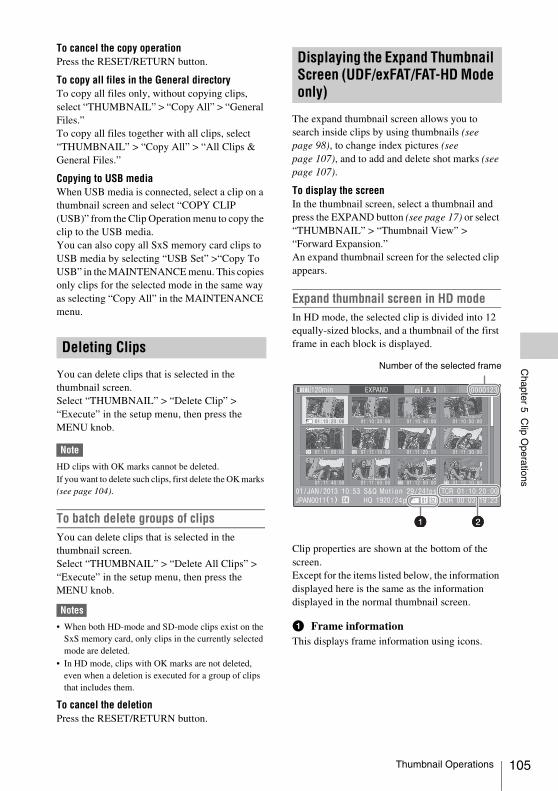
Chapter 5 C
lip Operations
To cancel the copy operationPress the RESET/RETURN button.
To copy all files in the General directoryTo copy all files only, without copying clips, select “THUMBNAIL” > “Copy All” > “General Files.”To copy all files together with all clips, select “THUMBNAIL” > “Copy All” > “All Clips & General Files.”
Copying to USB mediaWhen USB media is connected, select a clip on a thumbnail screen and select “COPY CLIP (USB)” from the Clip Operation menu to copy the clip to the USB media. You can also copy all SxS memory card clips to USB media by selecting “USB Set” >“Copy To USB” in the MAINTENANCE menu. This copies only clips for the selected mode in the same way as selecting “Copy All” in the MAINTENANCE menu.
You can delete clips that is selected in the thumbnail screen.Select “THUMBNAIL” > “Delete Clip” > “Execute” in the setup menu, then press the MENU knob.
Note
HD clips with OK marks cannot be deleted.If you want to delete such clips, first delete the OK marks (see page 104).
To batch delete groups of clipsYou can delete clips that is selected in the thumbnail screen.Select “THUMBNAIL” > “Delete All Clips” > “Execute” in the setup menu, then press the MENU knob.
Notes
• When both HD-mode and SD-mode clips exist on the SxS memory card, only clips in the currently selected mode are deleted.
• In HD mode, clips with OK marks are not deleted, even when a deletion is executed for a group of clips that includes them.
To cancel the deletionPress the RESET/RETURN button.
The expand thumbnail screen allows you to search inside clips by using thumbnails (see page 98), to change index pictures (see page 107), and to add and delete shot marks (see page 107).
To display the screenIn the thumbnail screen, select a thumbnail and press the EXPAND button (see page 17) or select “THUMBNAIL” > “Thumbnail View” > “Forward Expansion.”An expand thumbnail screen for the selected clip appears.
Expand thumbnail screen in HD modeIn HD mode, the selected clip is divided into 12 equally-sized blocks, and a thumbnail of the first frame in each block is displayed.
Clip properties are shown at the bottom of the screen.Except for the items listed below, the information displayed here is the same as the information displayed in the normal thumbnail screen.
a Frame informationThis displays frame information using icons.
Deleting Clips
Displaying the Expand Thumbnail Screen (UDF/exFAT/FAT-HD Mode only)
S1 S2
S2 S1
Number of the selected frame
Thumbnail Operations 105
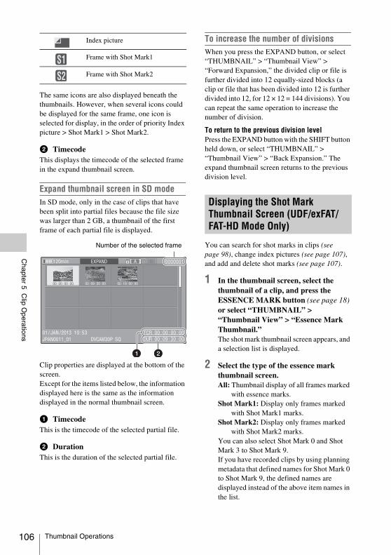
106
Chapter 5 C
lip Operations
The same icons are also displayed beneath the thumbnails. However, when several icons could be displayed for the same frame, one icon is selected for display, in the order of priority Index picture > Shot Mark1 > Shot Mark2.
b TimecodeThis displays the timecode of the selected frame in the expand thumbnail screen.
Expand thumbnail screen in SD modeIn SD mode, only in the case of clips that have been split into partial files because the file size was larger than 2 GB, a thumbnail of the first frame of each partial file is displayed.
Clip properties are displayed at the bottom of the screen.Except for the items listed below, the information displayed here is the same as the information displayed in the normal thumbnail screen.
a TimecodeThis is the timecode of the selected partial file.
b DurationThis is the duration of the selected partial file.
To increase the number of divisionsWhen you press the EXPAND button, or select “THUMBNAIL” > “Thumbnail View” > “Forward Expansion,” the divided clip or file is further divided into 12 equally-sized blocks (a clip or file that has been divided into 12 is further divided into 12, for 12 × 12 = 144 divisions). You can repeat the same operation to increase the number of division.
To return to the previous division levelPress the EXPAND button with the SHIFT button held down, or select “THUMBNAIL” > “Thumbnail View” > “Back Expansion.” The expand thumbnail screen returns to the previous division level.
You can search for shot marks in clips (see page 98), change index pictures (see page 107), and add and delete shot marks (see page 107).
1 In the thumbnail screen, select the thumbnail of a clip, and press the ESSENCE MARK button (see page 18) or select “THUMBNAIL” > “Thumbnail View” > “Essence Mark Thumbnail.”The shot mark thumbnail screen appears, and a selection list is displayed.
2 Select the type of the essence mark thumbnail screen.All: Thumbnail display of all frames marked
with essence marks.Shot Mark1: Display only frames marked
with Shot Mark1 marks.Shot Mark2: Display only frames marked
with Shot Mark2 marks.You can also select Shot Mark 0 and Shot Mark 3 to Shot Mark 9.If you have recorded clips by using planning metadata that defined names for Shot Mark 0 to Shot Mark 9, the defined names are displayed instead of the above item names in the list.
Index picture
Frame with Shot Mark1
Frame with Shot Mark2
S1S2
Number of the selected frame
Displaying the Shot Mark Thumbnail Screen (UDF/exFAT/FAT-HD Mode Only)
Thumbnail Operations
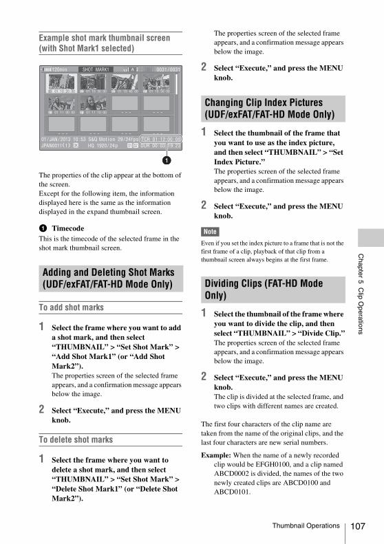
Chapter 5 C
lip Operations
Example shot mark thumbnail screen (with Shot Mark1 selected)
The properties of the clip appear at the bottom of the screen.Except for the following item, the information displayed here is the same as the information displayed in the expand thumbnail screen.
a TimecodeThis is the timecode of the selected frame in the shot mark thumbnail screen.
To add shot marks
1 Select the frame where you want to add a shot mark, and then select “THUMBNAIL” > “Set Shot Mark” > “Add Shot Mark1” (or “Add Shot Mark2”).The properties screen of the selected frame appears, and a confirmation message appears below the image.
2 Select “Execute,” and press the MENU knob.
To delete shot marks
1 Select the frame where you want to delete a shot mark, and then select “THUMBNAIL” > “Set Shot Mark” > “Delete Shot Mark1” (or “Delete Shot Mark2”).
The properties screen of the selected frame appears, and a confirmation message appears below the image.
2 Select “Execute,” and press the MENU knob.
1 Select the thumbnail of the frame that you want to use as the index picture, and then select “THUMBNAIL” > “Set Index Picture.”The properties screen of the selected frame appears, and a confirmation message appears below the image.
2 Select “Execute,” and press the MENU knob.
Note
Even if you set the index picture to a frame that is not the first frame of a clip, playback of that clip from a thumbnail screen always begins at the first frame.
1 Select the thumbnail of the frame where you want to divide the clip, and then select “THUMBNAIL” > “Divide Clip.”The properties screen of the selected frame appears, and a confirmation message appears below the image.
2 Select “Execute,” and press the MENU knob.The clip is divided at the selected frame, and two clips with different names are created.
The first four characters of the clip name are taken from the name of the original clips, and the last four characters are new serial numbers.
Example: When the name of a newly recorded clip would be EFGH0100, and a clip named ABCD0002 is divided, the names of the two newly created clips are ABCD0100 and ABCD0101.
Adding and Deleting Shot Marks (UDF/exFAT/FAT-HD Mode Only)
S1 S2 S2 S1
S1 S1
Changing Clip Index Pictures (UDF/exFAT/FAT-HD Mode Only)
Dividing Clips (FAT-HD Mode Only)
Thumbnail Operations 107
108
Chapter 5 C
lip Operations
Note
When there is not enough remaining capacity on the SxS memory cards to store the divided clips, a message appears to inform you that there is not enough capacity.
Thumbnail Operations
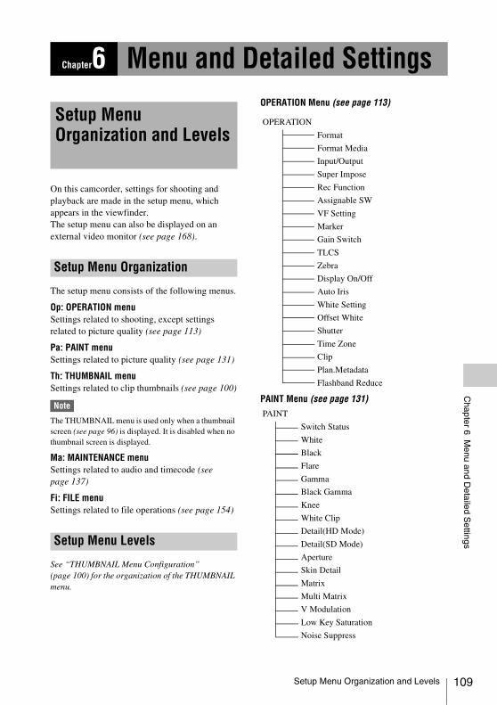
Chapter 6 M
enu and Detailed S
ettings
On this camcorder, settings for shooting and playback are made in the setup menu, which appears in the viewfinder.The setup menu can also be displayed on an external video monitor (see page 168).
The setup menu consists of the following menus.
Op: OPERATION menuSettings related to shooting, except settings related to picture quality (see page 113)
Pa: PAINT menuSettings related to picture quality (see page 131)
Th: THUMBNAIL menuSettings related to clip thumbnails (see page 100)
Note
The THUMBNAIL menu is used only when a thumbnail screen (see page 96) is displayed. It is disabled when no thumbnail screen is displayed.
Ma: MAINTENANCE menuSettings related to audio and timecode (see page 137)
Fi: FILE menuSettings related to file operations (see page 154)
See “THUMBNAIL Menu Configuration” (page 100) for the organization of the THUMBNAIL menu.
OPERATION Menu (see page 113)
PAINT Menu (see page 131)
Chapter6 Menu and Detailed Settings
Setup Menu Organization and Levels
Setup Menu Organization
Setup Menu Levels
OPERATION
Format
Format Media
Input/Output
Super Impose
Rec Function
Assignable SW
VF Setting
Marker
Gain Switch
TLCS
Zebra
Display On/Off
Auto Iris
White Setting
Offset White
Shutter
Time Zone
Clip
Plan.Metadata
Flashband Reduce
PAINT
Switch Status
White
Black
Flare
Gamma
Black Gamma
Knee
White Clip
Detail(HD Mode)
Detail(SD Mode)
Aperture
Skin Detail
Matrix
Multi Matrix
V Modulation
Low Key Saturation
Noise Suppress
Setup Menu Organization and Levels 109
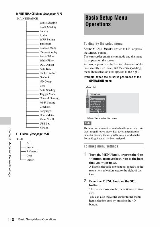
110
Chapter 6 M
enu and Detailed S
ettings
MAINTENANCE Menu (see page 137)
FILE Menu (see page 154)
To display the setup menuSet the MENU ON/OFF switch to ON, or press the MENU button.The camcorder enters menu mode and the menu list appears on the screen.A cursor appears over the first two characters of the most recently used menu, and the corresponding menu item selection area appears to the right.
Example: When the cursor is positioned at the OPERATION menu
Note
The setup menu cannot be used when the camcorder is in focus magnification mode. Exit focus magnification mode by pressing the assignable switch to which the Focus Mag function has been assigned.
To make menu settings
1 Turn the MENU knob, or press the J or j button, to move the cursor to the item that you want to set.A list of selectable menu items appears in the menu item selection area to the right of the icon.
2 Press the MENU knob or the SET button.The cursor moves to the menu item selection area.You can also move the cursor to the menu item selection area by pressing the k button.
MAINTENANCE
White Shading
Black Shading
Battery
Audio
WRR Setting
Timecode
Essence Mark
Camera Config
Preset White
White Filter
DCC Adjust
Auto Iris2
Flicker Reduce
Genlock
ND Comp
Lens
Auto Shading
Trigger Mode
Network Setting
Wi-Fi Setting
Clock set
Language
Hours Meter
Menu Scroll
USB Set
Version
FILE
All
Scene
Reference
Lens
Import
Basic Setup Menu Operations
Menu item selection area
Menu list
Basic Setup Menu Operations
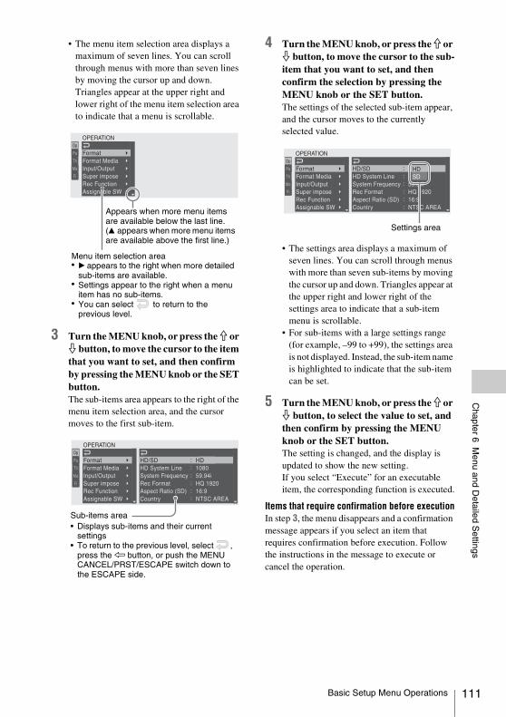
Chapter 6 M
enu and Detailed S
ettings
• The menu item selection area displays a maximum of seven lines. You can scroll through menus with more than seven lines by moving the cursor up and down.Triangles appear at the upper right and lower right of the menu item selection area to indicate that a menu is scrollable.
3 Turn the MENU knob, or press the J or j button, to move the cursor to the item that you want to set, and then confirm by pressing the MENU knob or the SET button.The sub-items area appears to the right of the menu item selection area, and the cursor moves to the first sub-item.
4 Turn the MENU knob, or press the J or j button, to move the cursor to the sub-item that you want to set, and then confirm the selection by pressing the MENU knob or the SET button.The settings of the selected sub-item appear, and the cursor moves to the currently selected value.
• The settings area displays a maximum of seven lines. You can scroll through menus with more than seven sub-items by moving the cursor up and down. Triangles appear at the upper right and lower right of the settings area to indicate that a sub-item menu is scrollable.
• For sub-items with a large settings range (for example, –99 to +99), the settings area is not displayed. Instead, the sub-item name is highlighted to indicate that the sub-item can be set.
5 Turn the MENU knob, or press the J or j button, to select the value to set, and then confirm by pressing the MENU knob or the SET button.The setting is changed, and the display is updated to show the new setting.If you select “Execute” for an executable item, the corresponding function is executed.
Items that require confirmation before executionIn step 3, the menu disappears and a confirmation message appears if you select an item that requires confirmation before execution. Follow the instructions in the message to execute or cancel the operation.
Appears when more menu items are available below the last line. (v appears when more menu items are available above the first line.)
Menu item selection area• B appears to the right when more detailed
sub-items are available.• Settings appear to the right when a menu
item has no sub-items.• You can select to return to the
previous level.
Sub-items area• Displays sub-items and their current
settings• To return to the previous level, select ,
press the K button, or push the MENU CANCEL/PRST/ESCAPE switch down to the ESCAPE side.
Settings area
Basic Setup Menu Operations 111
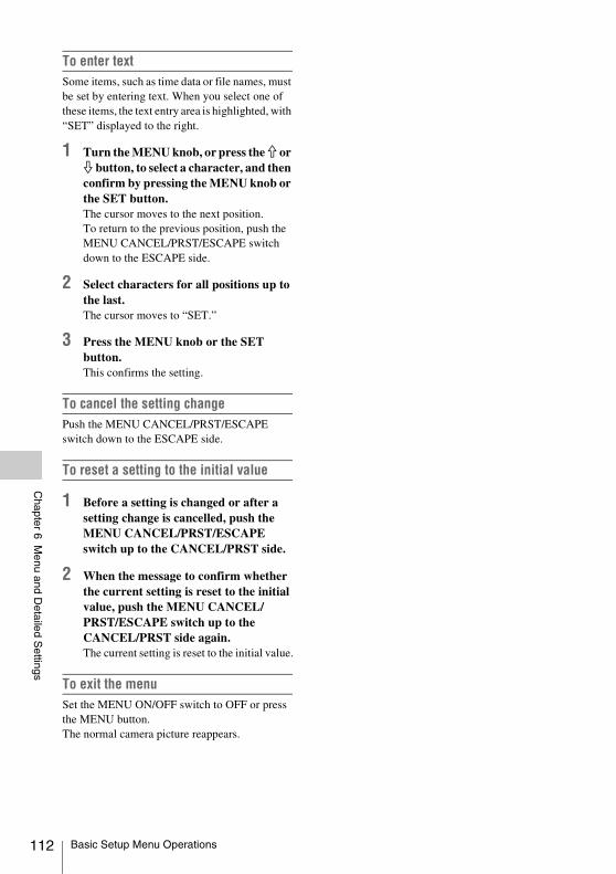
112
Chapter 6 M
enu and Detailed S
ettings
To enter text Some items, such as time data or file names, must be set by entering text. When you select one of these items, the text entry area is highlighted, with “SET” displayed to the right.
1 Turn the MENU knob, or press the J or j button, to select a character, and then confirm by pressing the MENU knob or the SET button.The cursor moves to the next position.To return to the previous position, push the MENU CANCEL/PRST/ESCAPE switch down to the ESCAPE side.
2 Select characters for all positions up to the last.The cursor moves to “SET.”
3 Press the MENU knob or the SET button.This confirms the setting.
To cancel the setting changePush the MENU CANCEL/PRST/ESCAPE switch down to the ESCAPE side.
To reset a setting to the initial value
1 Before a setting is changed or after a setting change is cancelled, push the MENU CANCEL/PRST/ESCAPE switch up to the CANCEL/PRST side.
2 When the message to confirm whether the current setting is reset to the initial value, push the MENU CANCEL/PRST/ESCAPE switch up to the CANCEL/PRST side again.The current setting is reset to the initial value.
To exit the menuSet the MENU ON/OFF switch to OFF or press the MENU button.The normal camera picture reappears.
Basic Setup Menu Operations
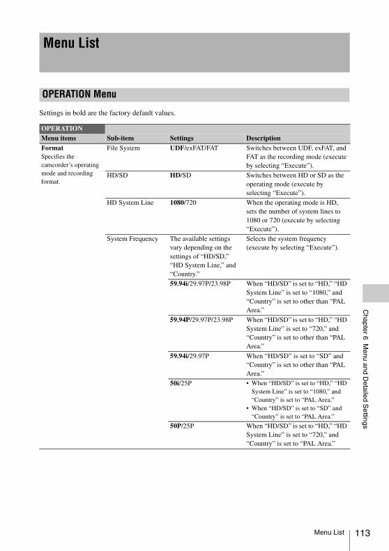
Chapter 6 M
enu and Detailed S
ettings
Settings in bold are the factory default values.
Menu List
OPERATION Menu
OPERATIONMenu items Sub-item Settings DescriptionFormatSpecifies the camcorder’s operating mode and recording format.
File System UDF/exFAT/FAT Switches between UDF, exFAT, and FAT as the recording mode (execute by selecting “Execute”).
HD/SD HD/SD Switches between HD or SD as the operating mode (execute by selecting “Execute”).
HD System Line 1080/720 When the operating mode is HD, sets the number of system lines to 1080 or 720 (execute by selecting “Execute”).
System Frequency The available settings vary depending on the settings of “HD/SD,” “HD System Line,” and “Country.”
Selects the system frequency (execute by selecting “Execute”).
59.94i/29.97P/23.98P When “HD/SD” is set to “HD,” “HD System Line” is set to “1080,” and “Country” is set to other than “PAL Area.”
59.94P/29.97P/23.98P When “HD/SD” is set to “HD,” “HD System Line” is set to “720,” and “Country” is set to other than “PAL Area.”
59.94i/29.97P When “HD/SD” is set to “SD” and “Country” is set to other than “PAL Area.”
50i/25P • When “HD/SD” is set to “HD,” “HD System Line” is set to “1080,” and “Country” is set to “PAL Area.”
• When “HD/SD” is set to “SD” and “Country” is set to “PAL Area.”
50P/25P When “HD/SD” is set to “HD,” “HD System Line” is set to “720,” and “Country” is set to “PAL Area.”
Menu List 113
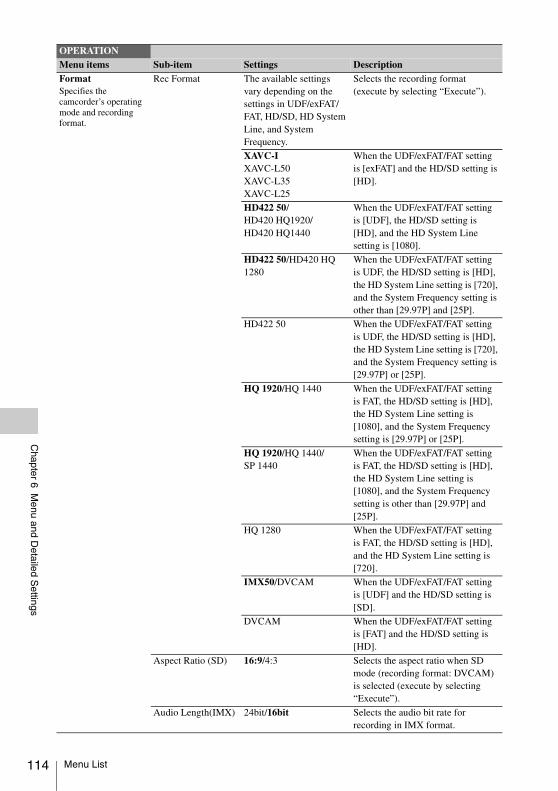
114
Chapter 6 M
enu and Detailed S
ettings
FormatSpecifies the camcorder’s operating mode and recording format.
Rec Format The available settings vary depending on the settings in UDF/exFAT/FAT, HD/SD, HD System Line, and System Frequency.
Selects the recording format (execute by selecting “Execute”).
XAVC-IXAVC-L50XAVC-L35XAVC-L25
When the UDF/exFAT/FAT setting is [exFAT] and the HD/SD setting is [HD].
HD422 50/HD420 HQ1920/HD420 HQ1440
When the UDF/exFAT/FAT setting is [UDF], the HD/SD setting is [HD], and the HD System Line setting is [1080].
HD422 50/HD420 HQ 1280
When the UDF/exFAT/FAT setting is UDF, the HD/SD setting is [HD], the HD System Line setting is [720], and the System Frequency setting is other than [29.97P] and [25P].
HD422 50 When the UDF/exFAT/FAT setting is UDF, the HD/SD setting is [HD], the HD System Line setting is [720], and the System Frequency setting is [29.97P] or [25P].
HQ 1920/HQ 1440 When the UDF/exFAT/FAT setting is FAT, the HD/SD setting is [HD], the HD System Line setting is [1080], and the System Frequency setting is [29.97P] or [25P].
HQ 1920/HQ 1440/SP 1440
When the UDF/exFAT/FAT setting is FAT, the HD/SD setting is [HD], the HD System Line setting is [1080], and the System Frequency setting is other than [29.97P] and [25P].
HQ 1280 When the UDF/exFAT/FAT setting is FAT, the HD/SD setting is [HD], and the HD System Line setting is [720].
IMX50/DVCAM When the UDF/exFAT/FAT setting is [UDF] and the HD/SD setting is [SD].
DVCAM When the UDF/exFAT/FAT setting is [FAT] and the HD/SD setting is [HD].
Aspect Ratio (SD) 16:9/4:3 Selects the aspect ratio when SD mode (recording format: DVCAM) is selected (execute by selecting “Execute”).
Audio Length(IMX) 24bit/16bit Selects the audio bit rate for recording in IMX format.
OPERATIONMenu items Sub-item Settings Description
Menu List
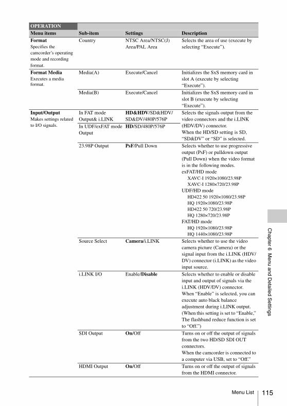
Chapter 6 M
enu and Detailed S
ettings
FormatSpecifies the camcorder’s operating mode and recording format.
Country NTSC Area/NTSC(J) Area/PAL Area
Selects the area of use (execute by selecting “Execute”).
Format MediaExecutes a media format.
Media(A) Execute/Cancel Initializes the SxS memory card in slot A (execute by selecting “Execute”).
Media(B) Execute/Cancel Initializes the SxS memory card in slot B (execute by selecting “Execute”).
Input/OutputMakes settings related to I/O signals.
In FAT modeOutput& i.LINK
HD&HDV/SD&HDV/SD&DV/480P/576P
Selects the signals output from the video connectors and the i.LINK (HDV/DV) connector.When the HD/SD setting is SD, “SD&DV” or “SD” is selected.
In UDF/exFAT modeOutput
HD/SD/480P/576P
23.98P Output PsF/Pull Down Selects whether to use progressive output (PsF) or pulldown output (Pull Down) when the video format is in the following modes.exFAT/HD mode
XAVC-I 1920×1080/23.98PXAVC-I 1280×720/23.98P
UDF/HD modeHD422 50 1920×1080/23.98PHQ 1920×1080/23.98PHD422 50 720/23.98PHQ 1280×720/23.98P
FAT/HD modeHQ 1920×1080/23.98PHQ 1440×1080/23.98P
Source Select Camera/i.LINK Selects whether to use the video camera picture (Camera) or the signal input from the i.LINK (HDV/DV) connector (i.LINK) as the video input source.
i.LINK I/O Enable/Disable Selects whether to enable or disable input and output of signals via the i.LINK (HDV/DV) connector.When “Enable” is selected, you can execute auto black balance adjustment during i.LINK output. (When this setting is set to “Enable,” The flashband reduce function is set to “Off.”)
SDI Output On/Off Turns on or off the output of signals from the two HD/SD SDI OUT connectors. When the camcorder is connected to a computer via USB, set to “Off.”
HDMI Output On/Off Turns on or off the output of signals from the HDMI connector.
OPERATIONMenu items Sub-item Settings Description
Menu List 115
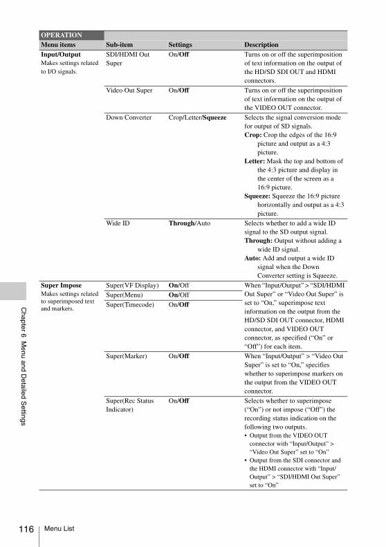
116
Chapter 6 M
enu and Detailed S
ettings
Input/OutputMakes settings related to I/O signals.
SDI/HDMI Out Super
On/Off Turns on or off the superimposition of text information on the output of the HD/SD SDI OUT and HDMI connectors.
Video Out Super On/Off Turns on or off the superimposition of text information on the output of the VIDEO OUT connector.
Down Converter Crop/Letter/Squeeze Selects the signal conversion mode for output of SD signals.Crop: Crop the edges of the 16:9
picture and output as a 4:3 picture.
Letter: Mask the top and bottom of the 4:3 picture and display in the center of the screen as a 16:9 picture.
Squeeze: Squeeze the 16:9 picture horizontally and output as a 4:3 picture.
Wide ID Through/Auto Selects whether to add a wide ID signal to the SD output signal.Through: Output without adding a
wide ID signal.Auto: Add and output a wide ID
signal when the Down Converter setting is Squeeze.
Super ImposeMakes settings related to superimposed text and markers.
Super(VF Display) On/Off When “Input/Output” > “SDI/HDMI Out Super” or “Video Out Super” is set to “On,” superimpose text information on the output from the HD/SD SDI OUT connector, HDMI connector, and VIDEO OUT connector, as specified (“On” or “Off”) for each item.
Super(Menu) On/Off
Super(Timecode) On/Off
Super(Marker) On/Off When “Input/Output” > “Video Out Super” is set to “On,” specifies whether to superimpose markers on the output from the VIDEO OUT connector.
Super(Rec Status Indicator)
On/Off Selects whether to superimpose (“On”) or not impose (“Off”) the recording status indication on the following two outputs.• Output from the VIDEO OUT
connector with “Input/Output” > “Video Out Super” set to “On”
• Output from the SDI connector and the HDMI connector with “Input/Output” > “SDI/HDMI Out Super” set to “On”
OPERATIONMenu items Sub-item Settings Description
Menu List
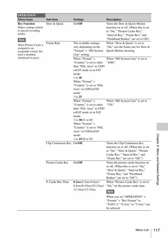
Chapter 6 M
enu and Detailed S
ettings
Rec FunctionMakes settings related to special recording modes.
Note
When Picture Cache is assigned to an assignable switch, this item is disabled (displayed in grey).
Slow & Quick On/Off Turns the Slow & Quick Motion function on or off. (When this is set to “On,” “Picture Cache Rec,” “Interval Rec,” “Frame Rec,” and “Flashband Reduce” are set to Off.)
Frame Rate The available settings vary depending on the “Format” > “HD System Line” setting.
When “Slow & Quick” is set to “On,” sets the frame rate for Slow & Quick Motion shooting.
When “Format” > “Country” is set to other than “PAL Area” in UDF/exFAT mode or in FAT mode: 1 to 30When “Format” > “Country” is set to “PAL Area” in UDF/exFAT mode: 1 to 25
When “HD System Line” is set to “1080.”
When “Format” > “Country” is set to other than “PAL Area” in UDF/exFAT mode or in FAT mode: 1 to 30/31 to 60When “Format” > “Country” is set to “PAL Area” in UDF/exFAT mode: 1 to 25/26 to 50
When “HD System Line” is set to “720.”
Clip Continuous Rec On/Off Turns the Clip Continuous Rec function on or off. (When this is set to “On,” “Slow & Quick,” “Picture Cache Rec,” “Interval Rec,” and “Frame Rec” are set to “Off.”)
Picture Cache Rec On/Off Turns the picture cache function on or off. (When this is set to “On,” “Slow & Quick,” “Interval Rec,” “Frame Rec,” and “Flashband Reduce” are set to “Off.”)
P. Cache Rec Time 0-2sec/2-4sec/4-6sec/6-8sec/8-10sec/10-12sec/12-14sec/13-15sec
When “Picture Cache Rec” is set to “On,” set the picture cache time.
Note
When you set “OPERATION” > “Format” > “Rec Format” to “XAVC-l,” “0-2sec” or “2-4sec” can be selected.
OPERATIONMenu items Sub-item Settings Description
Menu List 117
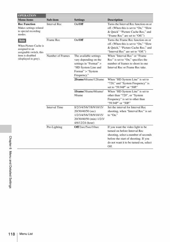
118
Chapter 6 M
enu and Detailed S
ettings
Rec FunctionMakes settings related to special recording modes.
Note
When Picture Cache is assigned to an assignable switch, this item is disabled (displayed in grey).
Interval Rec On/Off Turns the Interval Rec function on or off. (When this is set to “On,” “Slow & Quick” “Picture Cache Rec,” and “Frame Rec” are set to “Off.”)
Frame Rec On/Off Turns the Frame Rec function on or off. (When this is set to “On,” “Slow & Quick,” “Picture Cache Rec,” and “Interval Rec” are set to “Off.”)
Number of Frames The available settings vary depending on the settings in “Format” > “HD System Line and Format” > “System Frequency.”
When “Interval Rec” or “Frame Rec” is set to “On,” specifies the number of frames to shoot in one Interval Rec or Frame Rec take.
2frame/6frame/12frame When “HD System Line” is set to “720,” and “System Frequency” is set to “59.94P” or “50P.”
1frame/3frame/6frame/9frame
When “HD System Line” is set to other than “720”, or “System Frequency” is set to other than “59.94P” or “50P.”
Interval Time 1/2/3/4/5/6/7/8/9/10/15/20/30/40/50 (sec)1/2/3/4/5/6/7/8/9/10/15/20/30/40/50 (min) 1/2/3/4/6/12/24 (hour)
Set the interval for Interval Rec shooting, when “Interval Rec” is set to “On.”
Pre-Lighting Off/2sec/5sec/10sec If you want the video light to be turned on before Interval Rec shooting, select a number of seconds before the start of shooting. If you do not want it to be turned on, select Off.
OPERATIONMenu items Sub-item Settings Description
Menu List
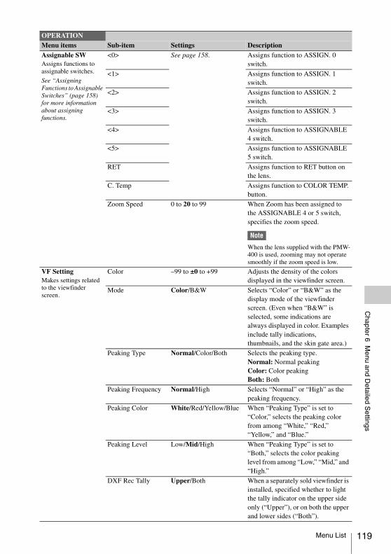
Chapter 6 M
enu and Detailed S
ettings
Assignable SWAssigns functions to assignable switches.
See “Assigning Functions to Assignable Switches” (page 158) for more information about assigning functions.
<0> See page 158. Assigns function to ASSIGN. 0 switch.
<1> Assigns function to ASSIGN. 1 switch.
<2> Assigns function to ASSIGN. 2 switch.
<3> Assigns function to ASSIGN. 3 switch.
<4> Assigns function to ASSIGNABLE 4 switch.
<5> Assigns function to ASSIGNABLE 5 switch.
RET Assigns function to RET button on the lens.
C. Temp Assigns function to COLOR TEMP. button.
Zoom Speed 0 to 20 to 99 When Zoom has been assigned to the ASSIGNABLE 4 or 5 switch, specifies the zoom speed.
Note
When the lens supplied with the PMW-400 is used, zooming may not operate smoothly if the zoom speed is low.
VF SettingMakes settings related to the viewfinder screen.
Color –99 to ±0 to +99 Adjusts the density of the colors displayed in the viewfinder screen.
Mode Color/B&W Selects “Color” or “B&W” as the display mode of the viewfinder screen. (Even when “B&W” is selected, some indications are always displayed in color. Examples include tally indications, thumbnails, and the skin gate area.)
Peaking Type Normal/Color/Both Selects the peaking type.Normal: Normal peakingColor: Color peakingBoth: Both
Peaking Frequency Normal/High Selects “Normal” or “High” as the peaking frequency.
Peaking Color White/Red/Yellow/Blue When “Peaking Type” is set to “Color,” selects the peaking color from among “White,” “Red,” “Yellow,” and “Blue.”
Peaking Level Low/Mid/High When “Peaking Type” is set to “Both,” selects the color peaking level from among “Low,” “Mid,” and “High.”
DXF Rec Tally Upper/Both When a separately sold viewfinder is installed, specified whether to light the tally indicator on the upper side only (“Upper”), or on both the upper and lower sides (“Both”).
OPERATIONMenu items Sub-item Settings Description
Menu List 119
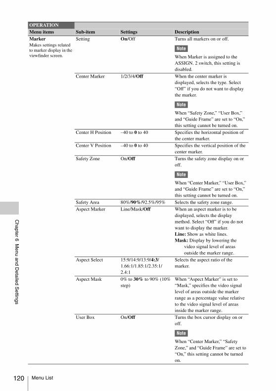
120
Chapter 6 M
enu and Detailed S
ettings
MarkerMakes settings related to marker display in the viewfinder screen.
Setting On/Off Turns all markers on or off.
Note
When Marker is assigned to the ASSIGN. 2 switch, this setting is disabled.
Center Marker 1/2/3/4/Off When the center marker is displayed, selects the type. Select “Off” if you do not want to display the marker.
Note
When “Safety Zone,” “User Box,” and “Guide Frame” are set to “On,” this setting cannot be turned on.
Center H Position –40 to 0 to 40 Specifies the horizontal position of the center marker.
Center V Position –40 to 0 to 40 Specifies the vertical position of the center marker.
Safety Zone On/Off Turns the safety zone display on or off.
Note
When “Center Marker,” “User Box,” and “Guide Frame” are set to “On,” this setting cannot be turned on.
Safety Area 80%/90%/92.5%/95% Selects the safety zone range.
Aspect Marker Line/Mask/Off When an aspect marker is to be displayed, selects the display method. Select “Off” if you do not want to display the marker.Line: Show as white lines.Mask: Display by lowering the
video signal level of areas outside the marker range.
Aspect Select 15:9/14:9/13:9/4:3/1.66:1/1.85:1/2.35:1/2.4:1
Selects the aspect ratio of the marker.
Aspect Mask 0% to 30% to 90% (10% step)
When “Aspect Marker” is set to “Mask,” specifies the video signal level of areas outside the marker range as a percentage value relative to the video signal level of areas inside the marker range.
User Box On/Off Turns the box cursor display on or off.
Note
When “Center Marker,” “Safety Zone,” and “Guide Frame” are set to “On,” this setting cannot be turned on.
OPERATIONMenu items Sub-item Settings Description
Menu List
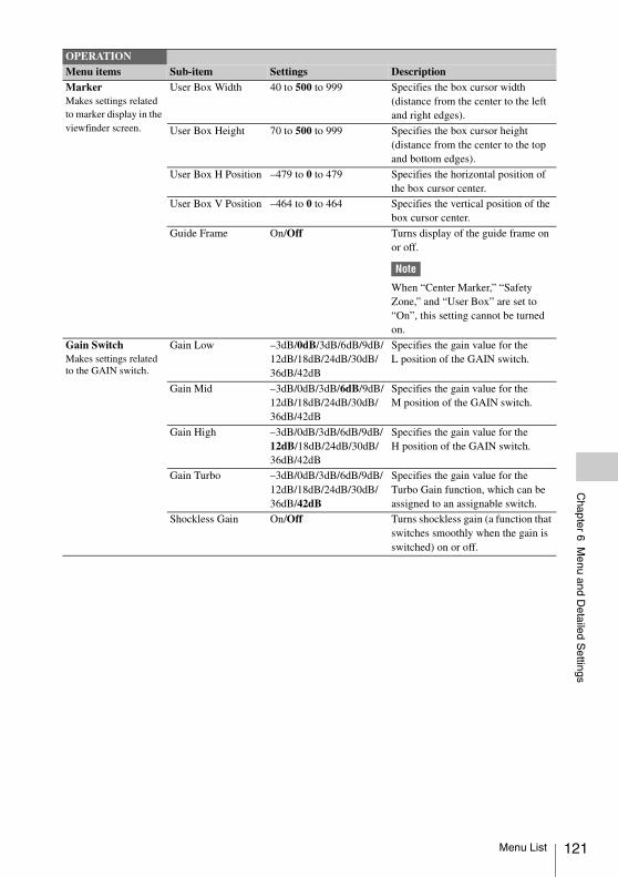
Chapter 6 M
enu and Detailed S
ettings
MarkerMakes settings related to marker display in the viewfinder screen.
User Box Width 40 to 500 to 999 Specifies the box cursor width (distance from the center to the left and right edges).
User Box Height 70 to 500 to 999 Specifies the box cursor height (distance from the center to the top and bottom edges).
User Box H Position –479 to 0 to 479 Specifies the horizontal position of the box cursor center.
User Box V Position –464 to 0 to 464 Specifies the vertical position of the box cursor center.
Guide Frame On/Off Turns display of the guide frame on or off.
Note
When “Center Marker,” “Safety Zone,” and “User Box” are set to “On”, this setting cannot be turned on.
Gain SwitchMakes settings related to the GAIN switch.
Gain Low –3dB/0dB/3dB/6dB/9dB/12dB/18dB/24dB/30dB/36dB/42dB
Specifies the gain value for the L position of the GAIN switch.
Gain Mid –3dB/0dB/3dB/6dB/9dB/12dB/18dB/24dB/30dB/36dB/42dB
Specifies the gain value for the M position of the GAIN switch.
Gain High –3dB/0dB/3dB/6dB/9dB/12dB/18dB/24dB/30dB/36dB/42dB
Specifies the gain value for the H position of the GAIN switch.
Gain Turbo –3dB/0dB/3dB/6dB/9dB/12dB/18dB/24dB/30dB/36dB/42dB
Specifies the gain value for the Turbo Gain function, which can be assigned to an assignable switch.
Shockless Gain On/Off Turns shockless gain (a function that switches smoothly when the gain is switched) on or off.
OPERATIONMenu items Sub-item Settings Description
Menu List 121
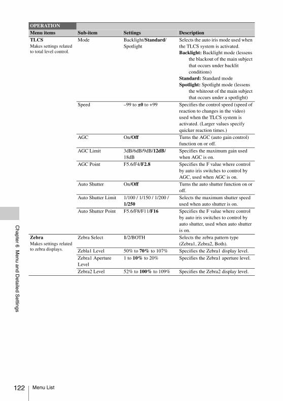
122
Chapter 6 M
enu and Detailed S
ettings
TLCSMakes settings related to total level control.
Mode Backlight/Standard/Spotlight
Selects the auto iris mode used when the TLCS system is activated.Backlight: Backlight mode (lessens
the blackout of the main subject that occurs under backlit conditions)
Standard: Standard modeSpotlight: Spotlight mode (lessens
the whiteout of the main subject that occurs under a spotlight)
Speed –99 to ±0 to +99 Specifies the control speed (speed of reaction to changes in the video) used when the TLCS system is activated. (Larger values specify quicker reaction times.)
AGC On/Off Turns the AGC (auto gain control) function on or off.
AGC Limit 3dB/6dB/9dB/12dB/18dB
Specifies the maximum gain used when AGC is on.
AGC Point F5.6/F4/F2.8 Specifies the F value where control by auto iris switches to control by AGC, used when AGC is on.
Auto Shutter On/Off Turns the auto shutter function on or off.
Auto Shutter Limit 1/100 / 1/150 / 1/200 / 1/250
Selects the maximum shutter speed used when auto shutter is on.
Auto Shutter Point F5.6/F8/F11/F16 Specifies the F value where control by auto iris switches to control by auto shutter, used when auto shutter is on.
ZebraMakes settings related to zebra displays.
Zebra Select 1/2/BOTH Selects the zebra pattern type (Zebra1, Zebra2, Both).
Zebla1 Level 50% to 70% to 107% Specifies the Zebra1 display level.
Zebra1 Aperture Level
1 to 10% to 20% Specifies the Zebra1 aperture level.
Zebra2 Level 52% to 100% to 109% Specifies the Zebra2 display level.
OPERATIONMenu items Sub-item Settings Description
Menu List
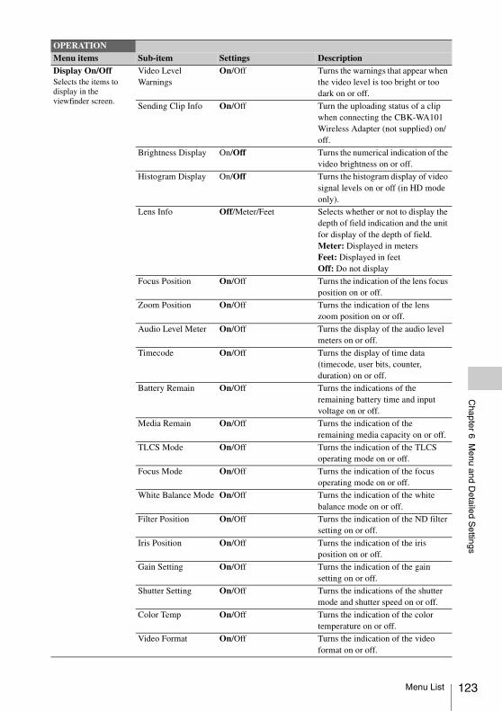
Chapter 6 M
enu and Detailed S
ettings
Display On/OffSelects the items to display in the viewfinder screen.
Video Level Warnings
On/Off Turns the warnings that appear when the video level is too bright or too dark on or off.
Sending Clip Info On/Off Turn the uploading status of a clip when connecting the CBK-WA101 Wireless Adapter (not supplied) on/off.
Brightness Display On/Off Turns the numerical indication of the video brightness on or off.
Histogram Display On/Off Turns the histogram display of video signal levels on or off (in HD mode only).
Lens Info Off/Meter/Feet Selects whether or not to display the depth of field indication and the unit for display of the depth of field.Meter: Displayed in metersFeet: Displayed in feetOff: Do not display
Focus Position On/Off Turns the indication of the lens focus position on or off.
Zoom Position On/Off Turns the indication of the lens zoom position on or off.
Audio Level Meter On/Off Turns the display of the audio level meters on or off.
Timecode On/Off Turns the display of time data (timecode, user bits, counter, duration) on or off.
Battery Remain On/Off Turns the indications of the remaining battery time and input voltage on or off.
Media Remain On/Off Turns the indication of the remaining media capacity on or off.
TLCS Mode On/Off Turns the indication of the TLCS operating mode on or off.
Focus Mode On/Off Turns the indication of the focus operating mode on or off.
White Balance Mode On/Off Turns the indication of the white balance mode on or off.
Filter Position On/Off Turns the indication of the ND filter setting on or off.
Iris Position On/Off Turns the indication of the iris position on or off.
Gain Setting On/Off Turns the indication of the gain setting on or off.
Shutter Setting On/Off Turns the indications of the shutter mode and shutter speed on or off.
Color Temp On/Off Turns the indication of the color temperature on or off.
Video Format On/Off Turns the indication of the video format on or off.
OPERATIONMenu items Sub-item Settings Description
Menu List 123
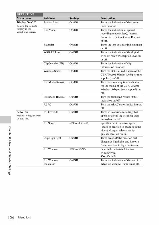
124
Chapter 6 M
enu and Detailed S
ettings
Display On/OffSelects the items to display in the viewfinder screen.
System Line On/Off Turns the indication of the system lines on or off.
Rec Mode On/Off Turns the indication of special recording modes (S&Q, Interval, Frame Rec, Picture Cache Rec) on or off.
Extender On/Off Turns the lens extender indication on or off.
WRR RF Level On/Off Turns the indication of the digital wireless receiver reception level on or off.
Clip Number(PB) On/Off Turns the indication of clip information on or off.
Wireless Status On/Off Turn the status of radio wave of the CBK-WA101 Wireless Adapter (not supplied) on/off.
Ext Media Remain On/Off Turn the remaining time indication for the media of the CBK-WA101 Wireless Adapter (not supplied) on/off.
Flashband Reduce On/Off Turn the flashband reduce status indication on/off.
ALAC On/Off Turn the ALAC status indication on/off.
Auto IrisMakes settings related to auto iris.
Iris Override On/Off Turns iris override (a setting that opens or closes the iris more than normal) on or off.
Iris Speed –99 to ±0 to +99 Specifies the iris control speed (speed of reaction to changes in the video). (Larger values specify quicker reaction times.)
Clip High light On/Off Turns on or off the function that disregards highlights and forces a flatter reaction to high luminance.
Iris Window 1/2/3/4/5/6/Var Selects the auto iris detection window type.Var: Variable
Iris Window Indication
On/Off Turns the indication of the auto iris detection window frame on or off.
OPERATIONMenu items Sub-item Settings Description
Menu List
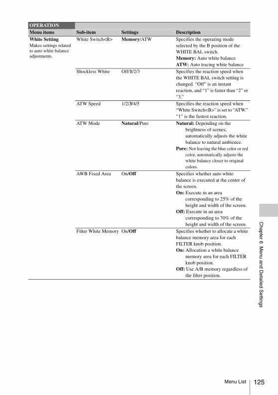
Chapter 6 M
enu and Detailed S
ettings
White SettingMakes settings related to auto white balance adjustments.
White Switch<B> Memory/ATW Specifies the operating mode selected by the B position of the WHITE BAL switch.Memory: Auto white balanceATW: Auto tracing white balance
Shockless White Off/1/2/3 Specifies the reaction speed when the WHITE BAL switch setting is changed. “Off” is an instant reaction, and “1” is faster than “2” or “3.”
ATW Speed 1/2/3/4/5 Specifies the reaction speed when “White Switch<B>” is set to “ATW.” “1” is the fastest reaction.
ATW Mode Natural/Pure Natural: Depending on the brightness of scenes, automatically adjusts the white balance to natural ambience.
Pure: Not leaving the blue color or red color, automatically adjusts the white balance closer to original colors.
AWB Fixed Area On/Off Specifies whether auto white balance is executed at the center of the screen.On: Execute in an area
corresponding to 25% of the height and width of the screen.
Off: Execute in an area corresponding to 70% of the height and width of the screen.
Filter White Memory On/Off Specifies whether to allocate a white balance memory area for each FILTER knob position.On: Allocation a white balance
memory area for each FILTER knob position.
Off: Use A/B memory regardless of the filter position.
OPERATIONMenu items Sub-item Settings Description
Menu List 125
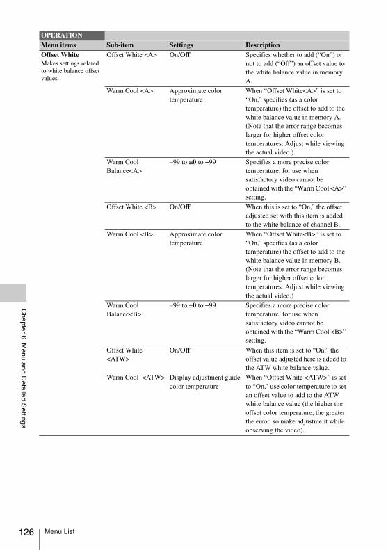
126
Chapter 6 M
enu and Detailed S
ettings
Offset WhiteMakes settings related to white balance offset values.
Offset White <A> On/Off Specifies whether to add (“On”) or not to add (“Off”) an offset value to the white balance value in memory A.
Warm Cool <A> Approximate color temperature
When “Offset White<A>” is set to “On,” specifies (as a color temperature) the offset to add to the white balance value in memory A. (Note that the error range becomes larger for higher offset color temperatures. Adjust while viewing the actual video.)
Warm Cool Balance<A>
–99 to ±0 to +99 Specifies a more precise color temperature, for use when satisfactory video cannot be obtained with the “Warm Cool <A>” setting.
Offset White <B> On/Off When this is set to “On,” the offset adjusted set with this item is added to the white balance of channel B.
Warm Cool <B> Approximate color temperature
When “Offset White<B>” is set to “On,” specifies (as a color temperature) the offset to add to the white balance value in memory B. (Note that the error range becomes larger for higher offset color temperatures. Adjust while viewing the actual video.)
Warm Cool Balance<B>
–99 to ±0 to +99 Specifies a more precise color temperature, for use when satisfactory video cannot be obtained with the “Warm Cool <B>” setting.
Offset White <ATW>
On/Off When this item is set to “On,” the offset value adjusted here is added to the ATW white balance value.
Warm Cool <ATW> Display adjustment guide color temperature
When “Offset White <ATW>” is set to “On,” use color temperature to set an offset value to add to the ATW white balance value (the higher the offset color temperature, the greater the error, so make adjustment while observing the video).
OPERATIONMenu items Sub-item Settings Description
Menu List
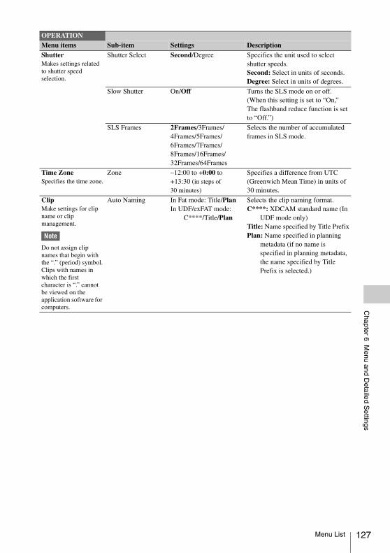
Chapter 6 M
enu and Detailed S
ettings
ShutterMakes settings related to shutter speed selection.
Shutter Select Second/Degree Specifies the unit used to select shutter speeds.Second: Select in units of seconds.Degree: Select in units of degrees.
Slow Shutter On/Off Turns the SLS mode on or off.(When this setting is set to “On,” The flashband reduce function is set to “Off.”)
SLS Frames 2Frames/3Frames/4Frames/5Frames/6Frames/7Frames/8Frames/16Frames/32Frames/64Frames
Selects the number of accumulated frames in SLS mode.
Time ZoneSpecifies the time zone.
Zone –12:00 to +0:00 to +13:30 (in steps of 30 minutes)
Specifies a difference from UTC (Greenwich Mean Time) in units of 30 minutes.
ClipMake settings for clip name or clip management.
Note
Do not assign clip names that begin with the “.” (period) symbol.Clips with names in which the first character is “.” cannot be viewed on the application software for computers.
Auto Naming In Fat mode: Title/PlanIn UDF/exFAT mode:
C****/Title/Plan
Selects the clip naming format.C****: XDCAM standard name (In
UDF mode only) Title: Name specified by Title PrefixPlan: Name specified in planning
metadata (if no name is specified in planning metadata, the name specified by Title Prefix is selected.)
OPERATIONMenu items Sub-item Settings Description
Menu List 127
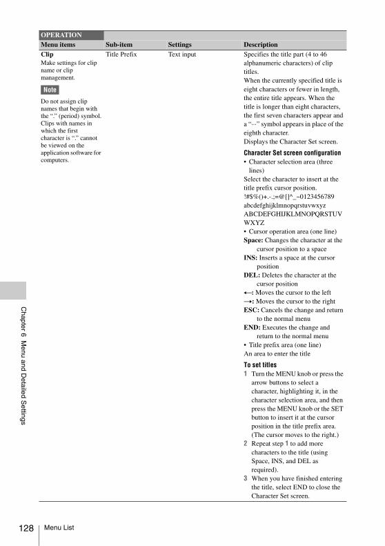
128
Chapter 6 M
enu and Detailed S
ettings
ClipMake settings for clip name or clip management.
Note
Do not assign clip names that begin with the “.” (period) symbol.Clips with names in which the first character is “.” cannot be viewed on the application software for computers.
Title Prefix Text input Specifies the title part (4 to 46 alphanumeric characters) of clip titles.When the currently specified title is eight characters or fewer in length, the entire title appears. When the title is longer than eight characters, the first seven characters appear and a “···” symbol appears in place of the eighth character.Displays the Character Set screen.
Character Set screen configuration• Character selection area (three
lines)Select the character to insert at the title prefix cursor position.!#$%()+.-.;=@[]^_~0123456789abcdefghijklmnopqrstuvwxyzABCDEFGHIJKLMNOPQRSTUVWXYZ• Cursor operation area (one line)Space: Changes the character at the
cursor position to a spaceINS: Inserts a space at the cursor
position DEL: Deletes the character at the
cursor position T: Moves the cursor to the leftt: Moves the cursor to the rightESC: Cancels the change and return
to the normal menu END: Executes the change and
return to the normal menu• Title prefix area (one line)An area to enter the title
To set titles1 Turn the MENU knob or press the
arrow buttons to select a character, highlighting it, in the character selection area, and then press the MENU knob or the SET button to insert it at the cursor position in the title prefix area. (The cursor moves to the right.)
2 Repeat step 1 to add more characters to the title (using Space, INS, and DEL as required).
3 When you have finished entering the title, select END to close the Character Set screen.
OPERATIONMenu items Sub-item Settings Description
Menu List
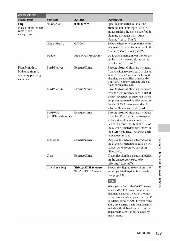
Chapter 6 M
enu and Detailed S
ettings
ClipMake settings for clip name or clip management.
Number Set 0001 to 9999 Specifies the initial value of the numeric part (four digits) of clip names (unless the name specified in planning metadata with “Auto Naming” set to “Plan”).
Name Display Off/On Selects whether to display the name of the next clips to be recorded in E-E mode (“On”) or not (“Off”).
Update Media<A>/Media<B> Updates the management files on the media in the selected slot (execute by selecting “Execute”).
Plan.MetadataMakes settings for operating planning metadata.
Load/Slot(A) Execute/Cancel Executes load of planning metadata from the SxS memory card in slot A. Select “Execute” to show the list of the planning metadata files stored in the slot A SxS memory card and select a file to execute the load.
Load/Slot(B) Execute/Cancel Executes load of planning metadata from the SxS memory card in slot B. Select “Execute” to show the list of the planning metadata files stored in the slot B SxS memory card and select a file to execute the load.
Load/USB(in UDF mode only)
Execute/Cancel Executes load of planning metadata from the USB flash drive connected to the external device connector. Select “Execute” to show the list of the planning metadata files stored in the USB flash drive and select a file to execute the load.
Properties Execute/Cancel Displays the detailed information in the planning metadata loaded on the camcorder (execute by selecting “Execute”).
Clear Execute/Cancel Clears the planning metadata loaded on the camcorder (execute by selecting “Execute”).
Clip Name Disp Title1(ASCII format)Title2(UTF-8 format)
Selects the display mode of the clip name specified in planning metadata (see page 95).
Note
When you define both of ASCII format name and UTF-8 format name with planning metadata, the UTF-8 format string is used as the clip name string. If you define either of ASCII format name and UTF-8 format name with planning metadata, the defined format name is displayed though it is not selected by menu setting.
OPERATIONMenu items Sub-item Settings Description
Menu List 129
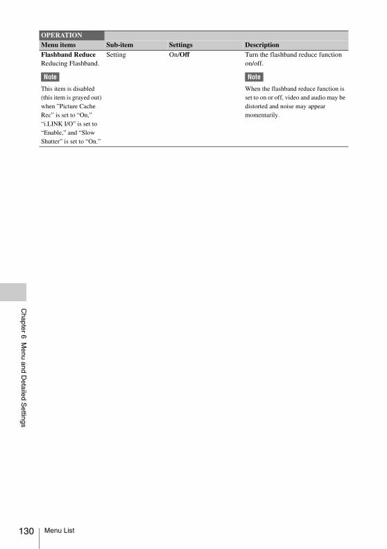
130
Chapter 6 M
enu and Detailed S
ettings
Flashband ReduceReducing Flashband.
Note
This item is disabled (this item is grayed out) when ”Picture Cache Rec” is set to “On,” “i.LINK I/O” is set to “Enable,” and “Slow Shutter” is set to “On.”
Setting On/Off Turn the flashband reduce function on/off.
Note
When the flashband reduce function is set to on or off, video and audio may be distorted and noise may appear momentarily.
OPERATIONMenu items Sub-item Settings Description
Menu List
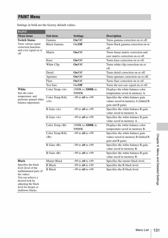
Chapter 6 M
enu and Detailed S
ettings
Settings in bold are the factory default values.
PAINT Menu
PAINTMenu items Sub-item Settings DescriptionSwitch StatusTurns various signal correction functions and a test signal on or off.
Gamma On/Off Turns gamma correction on or off.
Black Gamma On/Off Turns black gamma correction on or off.
Matrix On/Off Turns linear matrix correction and user matrix correction on or off.
Knee On/Off Turns knee correction on or off.
White Clip On/Off Turns white clip correction on or off.
Detail On/Off Turns detail correction on or off.
Aperture On/Off Turns aperture correction on or off.
Flare On/Off Turns flare correction on or off.
Test Saw On/Off Turns the test saw signal on or off.
WhiteSets the color temperature, and performs manual white balance adjustment.
Color Temp <A> 1500K to 3200K to 50000K
Displays the white balance color temperature saved in memory A.
Color Temp BAL <A>
–99 to ±0 to +99 Specifies the white balance gain values saved in memory A (linked R gain and B gain).
R Gain <A> –99 to ±0 to +99 Specifies the white balance R gain value saved in memory A.
B Gain <A> –99 to ±0 to +99 Specifies the white balance B gain value saved in memory A.
Color Temp <B> 1500K to 3200K to 50000K
Displays the white balance color temperature saved in memory B.
Color Temp BAL <B>
–99 to ±0 to +99 Specifies the white balance gain values saved in memory B (linked R gain and B gain).
R Gain <B> –99 to ±0 to +99 Specifies the white balance R gain value saved in memory B.
B Gain <B> –99 to ±0 to +99 Specifies the white balance B gain value saved in memory B.
BlackSpecifies the black level (level of the unilluminated parts of the video).You can achieve a desired look by adjusting the black level for deeper or shallower blacks.
Master Black –99 to ±0 to +99 Specifies the master black level.
R Black –99 to ±0 to +99 Specifies the R black level.
B Black –99 to ±0 to +99 Specifies the B black level.
Menu List 131
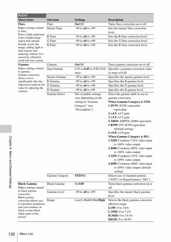
132
Chapter 6 M
enu and Detailed S
ettings
FlareMakes settings related to flare.Flare is light generated from a bright image region that spreads broadly across the image, adding light to dark regions and reducing contrast. It is caused by reflection inside the lens system.
Flare On/Off Turns flare correction on or off.
Master Flare –99 to ±0 to +99 Sets the master flare correction level.
R Flare –99 to ±0 to +99 Sets the R flare correction level.
G Flare –99 to ±0 to +99 Sets the G flare correction level.
B Flare –99 to ±0 to +99 Sets the B flare correction level.
GammaMakes settings related to gamma.Gamma correction allows you to significantly alter the impression made by the video by adjusting the contrast.
Gamma On/Off Turns gamma correction on or off.
Step Gamma 0.35 to 0.45 to 0.90 (0.05 step)
Specifies a gamma correction value in steps of 0.05
Master Gamma –99 to ±0 to +99 Specifies the master gamma level.
R Gamma –99 to ±0 to +99 Specifies the R gamma level.
G Gamma –99 to ±0 to +99 Specifies the G gamma level.
B Gamma –99 to ±0 to +99 Specifies the B gamma level.
Gamma Select The available settings vary depending on the setting in “Gamma Category” (see “Description”).
Select the gamma table to use in gamma correction.When Gamma Category is STD:1 DVW: DVW camcorder
equivalent2 ×4.5: ×4.5 gain3 ×3.5: ×3.5 gain4 240M: SMPTE-240M equivalent5 R709: ITU-R709 equivalent
(default setting)6 ×5.0: ×5.0 gainWhen Gamma Category is HG:1 3250: Condense 325% video input
to 100% video output2 4600: Condense 460% video input
to 100% video output3 3259: Condense 325% video input
to 109% video output4 4609: Condense 460% video input
to 109% video output (default setting)
Gamma Category STD/HG Selects use of standard gamma (“STD”) or HyperGamma (“HG”).
Black GammaMakes settings related to black gamma correction.Black gamma correction allows you to reproduce gradations and color nuances in black or near-black (dark) parts of the picture.
Black Gamma On/Off Turns black gamma correction on or off.
Gamma Level –99 to ±0 to +99 Specifies the master black gamma level.
Range Low/L.Mid/H.Mid/High Selects the black gamma correction effective range.LOW: 0 to 3.6%L.MID: 0 to 7.2%H.MID: 0 to 14.4%HIGH: 0 to 28.8%
PAINTMenu items Sub-item Settings Description
Menu List
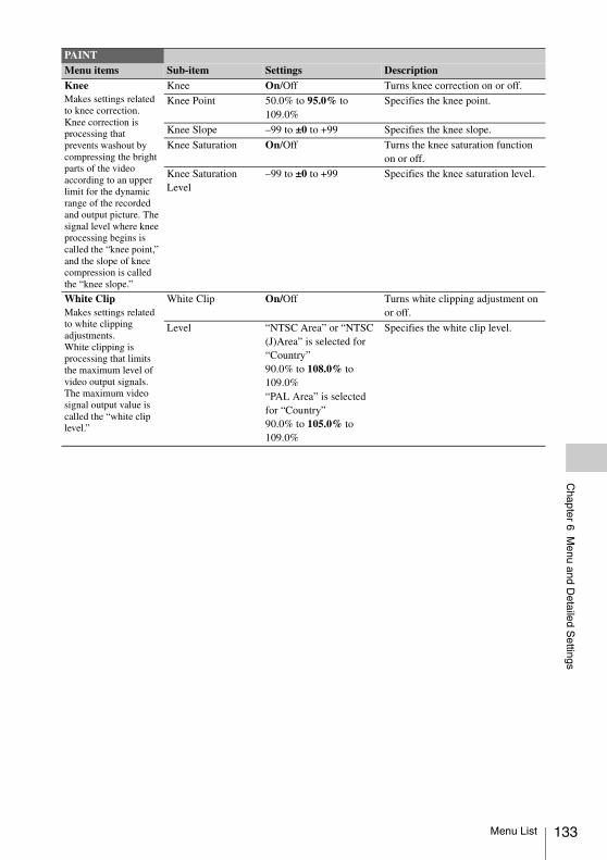
Chapter 6 M
enu and Detailed S
ettings
KneeMakes settings related to knee correction.Knee correction is processing that prevents washout by compressing the bright parts of the video according to an upper limit for the dynamic range of the recorded and output picture. The signal level where knee processing begins is called the “knee point,” and the slope of knee compression is called the “knee slope.”
Knee On/Off Turns knee correction on or off.
Knee Point 50.0% to 95.0% to 109.0%
Specifies the knee point.
Knee Slope –99 to ±0 to +99 Specifies the knee slope.
Knee Saturation On/Off Turns the knee saturation function on or off.
Knee Saturation Level
–99 to ±0 to +99 Specifies the knee saturation level.
White ClipMakes settings related to white clipping adjustments.White clipping is processing that limits the maximum level of video output signals. The maximum video signal output value is called the “white clip level.”
White Clip On/Off Turns white clipping adjustment on or off.
Level “NTSC Area” or “NTSC (J)Area” is selected for “Country”90.0% to 108.0% to 109.0%“PAL Area” is selected for “Country”90.0% to 105.0% to 109.0%
Specifies the white clip level.
PAINTMenu items Sub-item Settings Description
Menu List 133
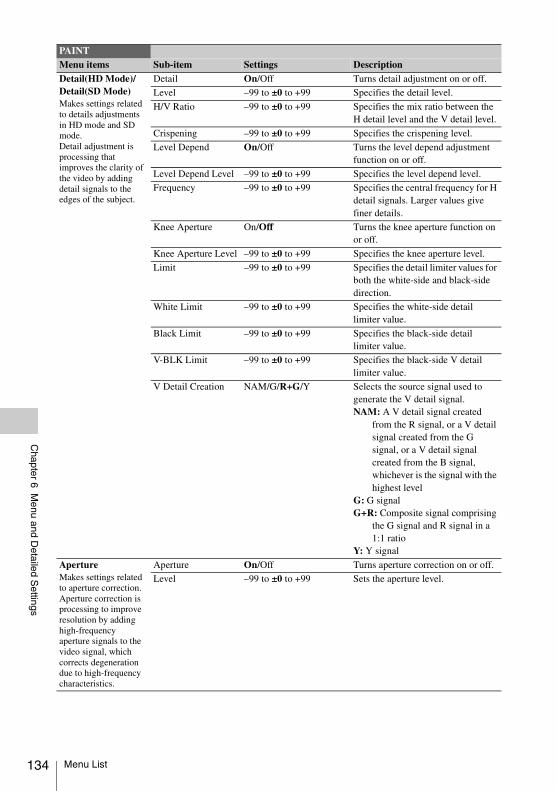
134
Chapter 6 M
enu and Detailed S
ettings
Detail(HD Mode)/Detail(SD Mode)Makes settings related to details adjustments in HD mode and SD mode.Detail adjustment is processing that improves the clarity of the video by adding detail signals to the edges of the subject.
Detail On/Off Turns detail adjustment on or off.
Level –99 to ±0 to +99 Specifies the detail level.
H/V Ratio –99 to ±0 to +99 Specifies the mix ratio between the H detail level and the V detail level.
Crispening –99 to ±0 to +99 Specifies the crispening level.
Level Depend On/Off Turns the level depend adjustment function on or off.
Level Depend Level –99 to ±0 to +99 Specifies the level depend level.
Frequency –99 to ±0 to +99 Specifies the central frequency for H detail signals. Larger values give finer details.
Knee Aperture On/Off Turns the knee aperture function on or off.
Knee Aperture Level –99 to ±0 to +99 Specifies the knee aperture level.
Limit –99 to ±0 to +99 Specifies the detail limiter values for both the white-side and black-side direction.
White Limit –99 to ±0 to +99 Specifies the white-side detail limiter value.
Black Limit –99 to ±0 to +99 Specifies the black-side detail limiter value.
V-BLK Limit –99 to ±0 to +99 Specifies the black-side V detail limiter value.
V Detail Creation NAM/G/R+G/Y Selects the source signal used to generate the V detail signal.NAM: A V detail signal created
from the R signal, or a V detail signal created from the G signal, or a V detail signal created from the B signal, whichever is the signal with the highest level
G: G signalG+R: Composite signal comprising
the G signal and R signal in a 1:1 ratio
Y: Y signal
ApertureMakes settings related to aperture correction.Aperture correction is processing to improve resolution by adding high-frequency aperture signals to the video signal, which corrects degeneration due to high-frequency characteristics.
Aperture On/Off Turns aperture correction on or off.
Level –99 to ±0 to +99 Sets the aperture level.
PAINTMenu items Sub-item Settings Description
Menu List
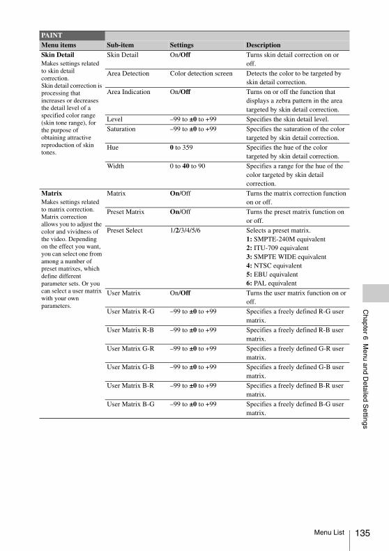
Chapter 6 M
enu and Detailed S
ettings
Skin DetailMakes settings related to skin detail correction.Skin detail correction is processing that increases or decreases the detail level of a specified color range (skin tone range), for the purpose of obtaining attractive reproduction of skin tones.
Skin Detail On/Off Turns skin detail correction on or off.
Area Detection Color detection screen Detects the color to be targeted by skin detail correction.
Area Indication On/Off Turns on or off the function that displays a zebra pattern in the area targeted by skin detail correction.
Level –99 to ±0 to +99 Specifies the skin detail level.
Saturation –99 to ±0 to +99 Specifies the saturation of the color targeted by skin detail correction.
Hue 0 to 359 Specifies the hue of the color targeted by skin detail correction.
Width 0 to 40 to 90 Specifies a range for the hue of the color targeted by skin detail correction.
MatrixMakes settings related to matrix correction.Matrix correction allows you to adjust the color and vividness of the video. Depending on the effect you want, you can select one from among a number of preset matrixes, which define different parameter sets. Or you can select a user matrix with your own parameters.
Matrix On/Off Turns the matrix correction function on or off.
Preset Matrix On/Off Turns the preset matrix function on or off.
Preset Select 1/2/3/4/5/6 Selects a preset matrix.1: SMPTE-240M equivalent2: ITU-709 equivalent3: SMPTE WIDE equivalent4: NTSC equivalent5: EBU equivalent6: PAL equivalent
User Matrix On/Off Turns the user matrix function on or off.
User Matrix R-G –99 to ±0 to +99 Specifies a freely defined R-G user matrix.
User Matrix R-B –99 to ±0 to +99 Specifies a freely defined R-B user matrix.
User Matrix G-R –99 to ±0 to +99 Specifies a freely defined G-R user matrix.
User Matrix G-B –99 to ±0 to +99 Specifies a freely defined G-B user matrix.
User Matrix B-R –99 to ±0 to +99 Specifies a freely defined B-R user matrix.
User Matrix B-G –99 to ±0 to +99 Specifies a freely defined B-G user matrix.
PAINTMenu items Sub-item Settings Description
Menu List 135
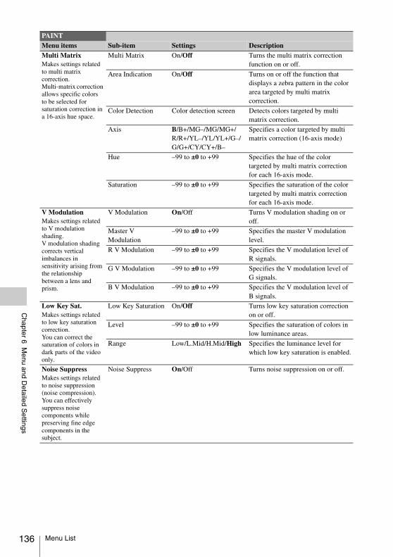
136
Chapter 6 M
enu and Detailed S
ettings
Multi MatrixMakes settings related to multi matrix correction.Multi-matrix correction allows specific colors to be selected for saturation correction in a 16-axis hue space.
Multi Matrix On/Off Turns the multi matrix correction function on or off.
Area Indication On/Off Turns on or off the function that displays a zebra pattern in the color area targeted by multi matrix correction.
Color Detection Color detection screen Detects colors targeted by multi matrix correction.
Axis B/B+/MG–/MG/MG+/R/R+/YL–/YL/YL+/G–/G/G+/CY/CY+/B–
Specifies a color targeted by multi matrix correction (16-axis mode)
Hue –99 to ±0 to +99 Specifies the hue of the color targeted by multi matrix correction for each 16-axis mode.
Saturation –99 to ±0 to +99 Specifies the saturation of the color targeted by multi matrix correction for each 16-axis mode.
V ModulationMakes settings related to V modulation shading.V modulation shading corrects vertical imbalances in sensitivity arising from the relationship between a lens and prism.
V Modulation On/Off Turns V modulation shading on or off.
Master V Modulation
–99 to ±0 to +99 Specifies the master V modulation level.
R V Modulation –99 to ±0 to +99 Specifies the V modulation level of R signals.
G V Modulation –99 to ±0 to +99 Specifies the V modulation level of G signals.
B V Modulation –99 to ±0 to +99 Specifies the V modulation level of B signals.
Low Key Sat.Makes settings related to low key saturation correction.You can correct the saturation of colors in dark parts of the video only.
Low Key Saturation On/Off Turns low key saturation correction on or off.
Level –99 to ±0 to +99 Specifies the saturation of colors in low luminance areas.
Range Low/L.Mid/H.Mid/High Specifies the luminance level for which low key saturation is enabled.
Noise SuppressMakes settings related to noise suppression (noise compression).You can effectively suppress noise components while preserving fine edge components in the subject.
Noise Suppress On/Off Turns noise suppression on or off.
PAINTMenu items Sub-item Settings Description
Menu List
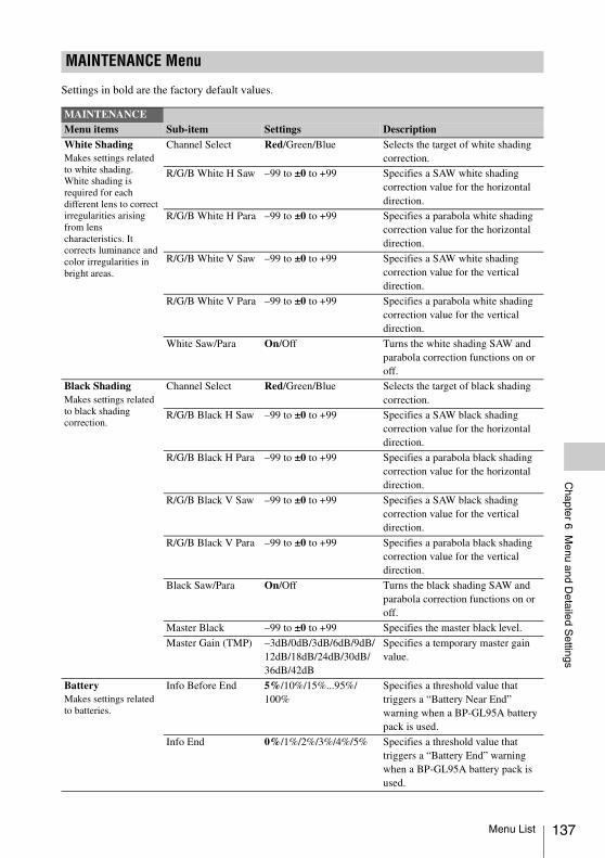
Chapter 6 M
enu and Detailed S
ettings
Settings in bold are the factory default values.
MAINTENANCE Menu
MAINTENANCEMenu items Sub-item Settings DescriptionWhite ShadingMakes settings related to white shading.White shading is required for each different lens to correct irregularities arising from lens characteristics. It corrects luminance and color irregularities in bright areas.
Channel Select Red/Green/Blue Selects the target of white shading correction.
R/G/B White H Saw –99 to ±0 to +99 Specifies a SAW white shading correction value for the horizontal direction.
R/G/B White H Para –99 to ±0 to +99 Specifies a parabola white shading correction value for the horizontal direction.
R/G/B White V Saw –99 to ±0 to +99 Specifies a SAW white shading correction value for the vertical direction.
R/G/B White V Para –99 to ±0 to +99 Specifies a parabola white shading correction value for the vertical direction.
White Saw/Para On/Off Turns the white shading SAW and parabola correction functions on or off.
Black ShadingMakes settings related to black shading correction.
Channel Select Red/Green/Blue Selects the target of black shading correction.
R/G/B Black H Saw –99 to ±0 to +99 Specifies a SAW black shading correction value for the horizontal direction.
R/G/B Black H Para –99 to ±0 to +99 Specifies a parabola black shading correction value for the horizontal direction.
R/G/B Black V Saw –99 to ±0 to +99 Specifies a SAW black shading correction value for the vertical direction.
R/G/B Black V Para –99 to ±0 to +99 Specifies a parabola black shading correction value for the vertical direction.
Black Saw/Para On/Off Turns the black shading SAW and parabola correction functions on or off.
Master Black –99 to ±0 to +99 Specifies the master black level.
Master Gain (TMP) –3dB/0dB/3dB/6dB/9dB/12dB/18dB/24dB/30dB/36dB/42dB
Specifies a temporary master gain value.
BatteryMakes settings related to batteries.
Info Before End 5%/10%/15%...95%/100%
Specifies a threshold value that triggers a “Battery Near End” warning when a BP-GL95A battery pack is used.
Info End 0%/1%/2%/3%/4%/5% Specifies a threshold value that triggers a “Battery End” warning when a BP-GL95A battery pack is used.
Menu List 137
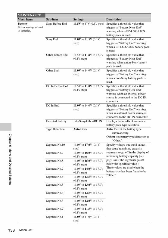
138
Chapter 6 M
enu and Detailed S
ettings
BatteryMakes settings related to batteries.
Sony Before End 11.5V to 17V (0.1V step) Specifies a threshold value that triggers a “Battery Near End” warning when a BP-L60S/L80S battery pack is used.
Sony End 11.0V to 11.5V (0.1V step)
Specifies a threshold value that triggers a “Battery End” warning when a BP-L60S/L80S battery pack is used.
Other Before End 11.5V to 11.8V to 17.0V (0.1V step)
Specifies a threshold value that triggers a “Battery Near End” warning when a non-Sony battery pack is used.
Other End 11.0V to 14.0V (0.1V step)
Specifies a threshold value that triggers a “Battery End” warning when a non-Sony battery pack is used.
DC In Before End 11.5V to 11.8V to 17.0V (0.1V step)
Specifies a threshold value that triggers a “Battery Near End” warning when an external power source is connected to the DC IN connector.
DC In End 11.0V to 14.0V (0.1V step)
Specifies a threshold value that triggers a “Battery End” warning when an external power source is connected to the DC IN connector.
Detected Battery Info/Sony/Other/DC IN Displays the results of automatic battery pack type detection.
Type Detection Auto/Other Auto: Detect the battery type automatically.
Other: Fix battery type detection as “Other.”
Segment No.10 11.0V to 17.0V (0.1V step)
Specify voltage threshold values that cause remaining capacity segments to go off in the display of remaining battery capacity (see page 26). (The segments go off below the specified value.)These values are used when the battery type has been found to be “Other.”
Segment No.9 11.0V to 16.0V to 17.0V (0.1V step)
Segment No.8 11.0V to 15.0V to 17.0V (0.1V step)
Segment No.7 11.0V to 14.0V to 17.0V (0.1V step)
Segment No.6 11.0V to 13.5V to 17.0V (0.1V step)
Segment No.5 11.0V to 13.0V to 17.0V (0.1V step)
Segment No.4 11.0V to 12.5V to 17.0V (0.1V step)
Segment No.3 11.0V to 12.0V to 17.0V (0.1V step)
Segment No.2 11.0V to 11.5V to 17.0V (0.1V step)
Segment No.1 11.0V to 17.0V (0.1V step)
MAINTENANCEMenu items Sub-item Settings Description
Menu List
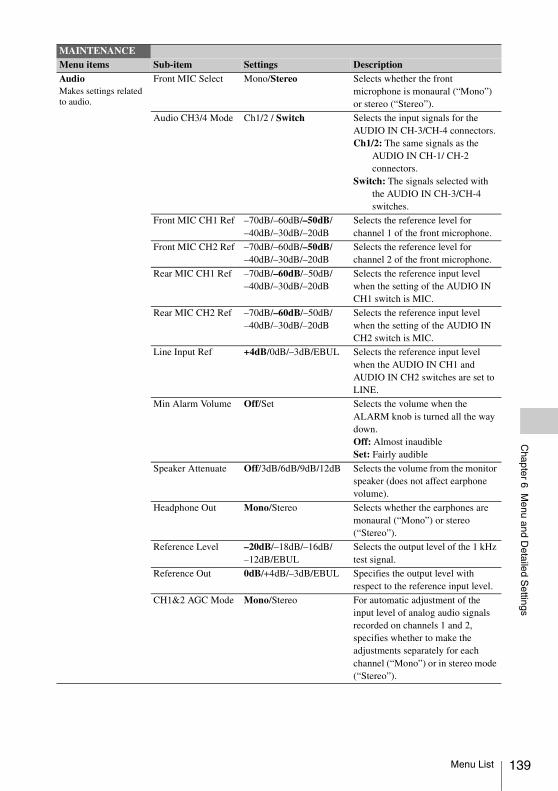
Chapter 6 M
enu and Detailed S
ettings
AudioMakes settings related to audio.
Front MIC Select Mono/Stereo Selects whether the front microphone is monaural (“Mono”) or stereo (“Stereo”).
Audio CH3/4 Mode Ch1/2 / Switch Selects the input signals for the AUDIO IN CH-3/CH-4 connectors.Ch1/2: The same signals as the
AUDIO IN CH-1/ CH-2 connectors.
Switch: The signals selected with the AUDIO IN CH-3/CH-4 switches.
Front MIC CH1 Ref –70dB/–60dB/–50dB/–40dB/–30dB/–20dB
Selects the reference level for channel 1 of the front microphone.
Front MIC CH2 Ref –70dB/–60dB/–50dB/–40dB/–30dB/–20dB
Selects the reference level for channel 2 of the front microphone.
Rear MIC CH1 Ref –70dB/–60dB/–50dB/–40dB/–30dB/–20dB
Selects the reference input level when the setting of the AUDIO IN CH1 switch is MIC.
Rear MIC CH2 Ref –70dB/–60dB/–50dB/–40dB/–30dB/–20dB
Selects the reference input level when the setting of the AUDIO IN CH2 switch is MIC.
Line Input Ref +4dB/0dB/–3dB/EBUL Selects the reference input level when the AUDIO IN CH1 and AUDIO IN CH2 switches are set to LINE.
Min Alarm Volume Off/Set Selects the volume when the ALARM knob is turned all the way down.Off: Almost inaudibleSet: Fairly audible
Speaker Attenuate Off/3dB/6dB/9dB/12dB Selects the volume from the monitor speaker (does not affect earphone volume).
Headphone Out Mono/Stereo Selects whether the earphones are monaural (“Mono”) or stereo (“Stereo”).
Reference Level –20dB/–18dB/–16dB/–12dB/EBUL
Selects the output level of the 1 kHz test signal.
Reference Out 0dB/+4dB/–3dB/EBUL Specifies the output level with respect to the reference input level.
CH1&2 AGC Mode Mono/Stereo For automatic adjustment of the input level of analog audio signals recorded on channels 1 and 2, specifies whether to make the adjustments separately for each channel (“Mono”) or in stereo mode (“Stereo”).
MAINTENANCEMenu items Sub-item Settings Description
Menu List 139
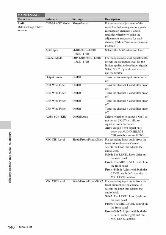
140
Chapter 6 M
enu and Detailed S
ettings
AudioMakes settings related to audio.
CH3&4 AGC Mode Mono/Stereo For automatic adjustment of the input level of analog audio signals recorded on channels 3 and 4, specifies whether to make the adjustments separately for each channel (“Mono”) or in stereo mode (“Stereo”).
AGC Spec –6dB/–9dB/–12dB/–15dB/–17dB
Selects the AGC saturation level.
Limiter Mode Off/–6dB/–9dB/–12dB/–15dB/–17dB
For manual audio level adjustments, selects the saturation level for the limiter applied to loud input signals.Select “Off” if you do not wish to use the limiter.
Output Limiter On/Off Turns the audio output limiter on or off.
CH1 Wind Filter On/Off Turns the channel 1 wind filter on or off.
CH2 Wind Filter On/Off Turns the channel 2 wind filter on or off.
CH3 Wind Filter On/Off Turns the channel 3 wind filter on or off.
CH4 Wind Filter On/Off Turns the channel 4 wind filter on or off.
Audio SG (1KHz) On/Off/Auto Selects whether to output (“On”) or not output (“Off”) a 1 kHz test signal in color bar mode.Auto: Output a test signal only
when the AUDIO SELECT CH1 switch is set to AUTO.
MIC CH1 Level Side1/Front/Front+Side1 For recording input audio from the front microphone on channel 1, selects the knob that adjusts the audio level. Side1: The LEVEL knob (left) on
the side panelFront: The MIC LEVEL control on
the front panelFront+Side1: Adjust with both the
LEVEL knob (left) and the MIC LEVEL control.
MIC CH2 Level Side2/Front/Front+Side2 For recording input audio from the front microphone on channel 2, selects the knob that adjusts the audio level.Side2: The LEVEL knob (right) on
the side panelFront: The MIC LEVEL control on
the front panelFront+Side2: Adjust with both the
LEVEL knob (right) and the MIC LEVEL control.
MAINTENANCEMenu items Sub-item Settings Description
Menu List
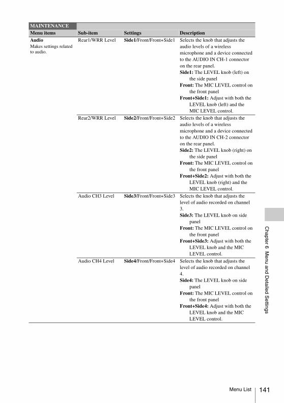
Chapter 6 M
enu and Detailed S
ettings
AudioMakes settings related to audio.
Rear1/WRR Level Side1/Front/Front+Side1 Selects the knob that adjusts the audio levels of a wireless microphone and a device connected to the AUDIO IN CH-1 connector on the rear panel.Side1: The LEVEL knob (left) on
the side panelFront: The MIC LEVEL control on
the front panel Front+Side1: Adjust with both the
LEVEL knob (left) and the MIC LEVEL control.
Rear2/WRR Level Side2/Front/Front+Side2 Selects the knob that adjusts the audio levels of a wireless microphone and a device connected to the AUDIO IN CH-2 connector on the rear panel.Side2: The LEVEL knob (right) on
the side panelFront: The MIC LEVEL control on
the front panelFront+Side2: Adjust with both the
LEVEL knob (right) and the MIC LEVEL control.
Audio CH3 Level Side3/Front/Front+Side3 Selects the knob that adjusts the level of audio recorded on channel 3. Side3: The LEVEL knob on side
panelFront: The MIC LEVEL control on
the front panelFront+Side3: Adjust with both the
LEVEL knob and the MIC LEVEL control.
Audio CH4 Level Side4/Front/Front+Side4 Selects the knob that adjusts the level of audio recorded on channel 4.Side4: The LEVEL knob on side
panelFront: The MIC LEVEL control on
the front panelFront+Side4: Adjust with both the
LEVEL knob and the MIC LEVEL control.
MAINTENANCEMenu items Sub-item Settings Description
Menu List 141
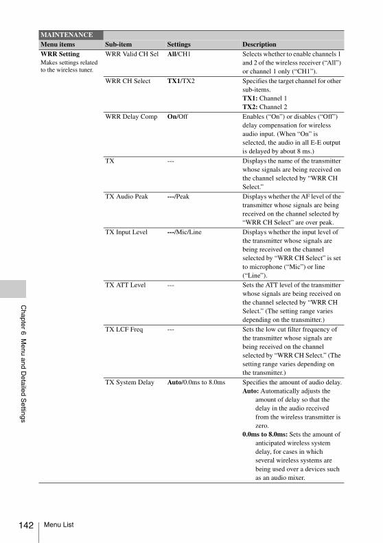
142
Chapter 6 M
enu and Detailed S
ettings
WRR SettingMakes settings related to the wireless tuner.
WRR Valid CH Sel All/CH1 Selects whether to enable channels 1 and 2 of the wireless receiver (“All”) or channel 1 only (“CH1”).
WRR CH Select TX1/TX2 Specifies the target channel for other sub-items.TX1: Channel 1TX2: Channel 2
WRR Delay Comp On/Off Enables (“On”) or disables (“Off”) delay compensation for wireless audio input. (When “On” is selected, the audio in all E-E output is delayed by about 8 ms.)
TX --- Displays the name of the transmitter whose signals are being received on the channel selected by “WRR CH Select.”
TX Audio Peak ---/Peak Displays whether the AF level of the transmitter whose signals are being received on the channel selected by “WRR CH Select” are over peak.
TX Input Level ---/Mic/Line Displays whether the input level of the transmitter whose signals are being received on the channel selected by “WRR CH Select” is set to microphone (“Mic”) or line (“Line”).
TX ATT Level --- Sets the ATT level of the transmitter whose signals are being received on the channel selected by “WRR CH Select.” (The setting range varies depending on the transmitter.)
TX LCF Freq --- Sets the low cut filter frequency of the transmitter whose signals are being received on the channel selected by “WRR CH Select.” (The setting range varies depending on the transmitter.)
TX System Delay Auto/0.0ms to 8.0ms Specifies the amount of audio delay.Auto: Automatically adjusts the
amount of delay so that the delay in the audio received from the wireless transmitter is zero.
0.0ms to 8.0ms: Sets the amount of anticipated wireless system delay, for cases in which several wireless systems are being used over a devices such as an audio mixer.
MAINTENANCEMenu items Sub-item Settings Description
Menu List
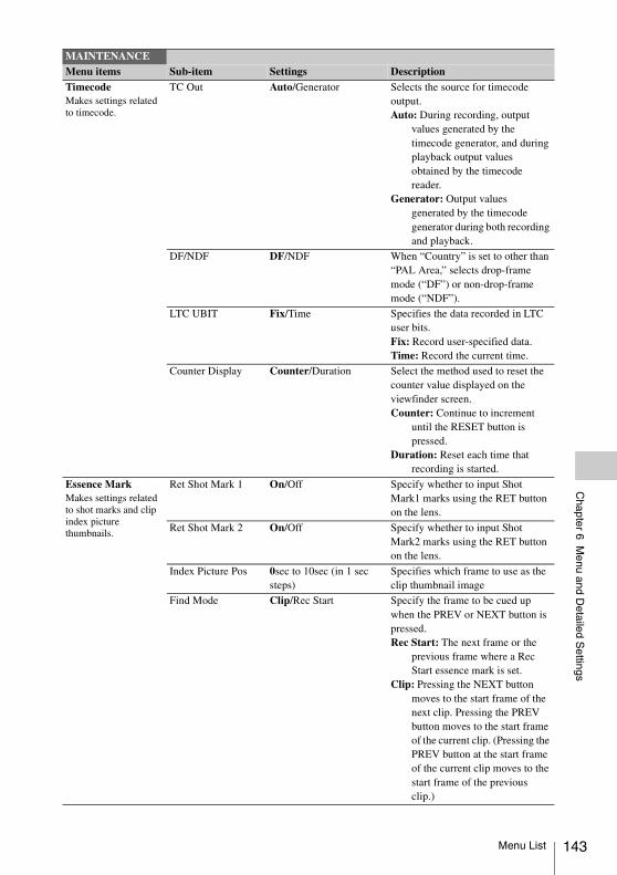
Chapter 6 M
enu and Detailed S
ettings
TimecodeMakes settings related to timecode.
TC Out Auto/Generator Selects the source for timecode output.Auto: During recording, output
values generated by the timecode generator, and during playback output values obtained by the timecode reader.
Generator: Output values generated by the timecode generator during both recording and playback.
DF/NDF DF/NDF When “Country” is set to other than “PAL Area,” selects drop-frame mode (“DF”) or non-drop-frame mode (“NDF”).
LTC UBIT Fix/Time Specifies the data recorded in LTC user bits. Fix: Record user-specified data.Time: Record the current time.
Counter Display Counter/Duration Select the method used to reset the counter value displayed on the viewfinder screen. Counter: Continue to increment
until the RESET button is pressed.
Duration: Reset each time that recording is started.
Essence MarkMakes settings related to shot marks and clip index picture thumbnails.
Ret Shot Mark 1 On/Off Specify whether to input Shot Mark1 marks using the RET button on the lens.
Ret Shot Mark 2 On/Off Specify whether to input Shot Mark2 marks using the RET button on the lens.
Index Picture Pos 0sec to 10sec (in 1 sec steps)
Specifies which frame to use as the clip thumbnail image
Find Mode Clip/Rec Start Specify the frame to be cued up when the PREV or NEXT button is pressed.Rec Start: The next frame or the
previous frame where a Rec Start essence mark is set.
Clip: Pressing the NEXT button moves to the start frame of the next clip. Pressing the PREV button moves to the start frame of the current clip. (Pressing the PREV button at the start frame of the current clip moves to the start frame of the previous clip.)
MAINTENANCEMenu items Sub-item Settings Description
Menu List 143
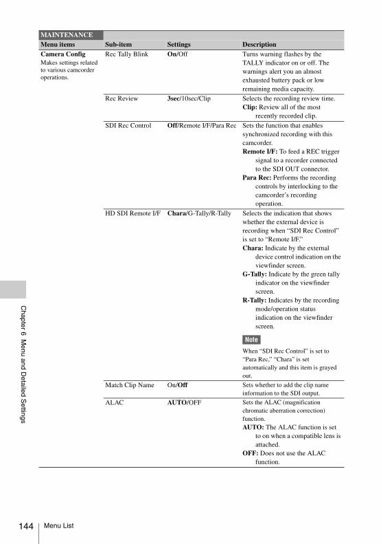
144
Chapter 6 M
enu and Detailed S
ettings
Camera ConfigMakes settings related to various camcorder operations.
Rec Tally Blink On/Off Turns warning flashes by the TALLY indicator on or off. The warnings alert you an almost exhausted battery pack or low remaining media capacity.
Rec Review 3sec/10sec/Clip Selects the recording review time.Clip: Review all of the most
recently recorded clip.
SDI Rec Control Off/Remote I/F/Para Rec Sets the function that enables synchronized recording with this camcorder.Remote I/F: To feed a REC trigger
signal to a recorder connected to the SDI OUT connector.
Para Rec: Performs the recording controls by interlocking to the camcorder’s recording operation.
HD SDI Remote I/F Chara/G-Tally/R-Tally Selects the indication that shows whether the external device is recording when “SDI Rec Control” is set to “Remote I/F.”Chara: Indicate by the external
device control indication on the viewfinder screen.
G-Tally: Indicate by the green tally indicator on the viewfinder screen.
R-Tally: Indicates by the recording mode/operation status indication on the viewfinder screen.
Note
When “SDI Rec Control” is set to “Para Rec,” “Chara” is set automatically and this item is grayed out.
Match Clip Name On/Off Sets whether to add the clip name information to the SDI output.
ALAC AUTO/OFF Sets the ALAC (magnification chromatic aberration correction) function.AUTO: The ALAC function is set
to on when a compatible lens is attached.
OFF: Does not use the ALAC function.
MAINTENANCEMenu items Sub-item Settings Description
Menu List
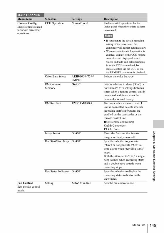
Chapter 6 M
enu and Detailed S
ettings
Camera ConfigMakes settings related to various camcorder operations.
CCU Operation Normal/Local Enables switch operations for the inside panel when the camera adapter is mounted.
Notes
• If you change the switch operation setting of the camcorder, the camcorder will restart automatically.
• When main unit switch operation is enabled, display of the CCU remote controller and display of return videos and tally and call operations from the CCU are enabled, but remote control via the CCU or via the REMOTE connector is disabled.
Color Bars Select ARIB/100%/75%/SMPTE
Selects the color bar type.
RM Common Memory
On/Off Selects whether to share (“On”) or not share (“Off”) settings between times when a remote control unit is connected and times when the camcorder is used locally.
RM Rec Start RM/CAM/PARA For times when a remote control unit is connected, selects whether recording start/stop buttons are enabled on the camcorder or the remote control unit. RM: Remote control unitCAM: Camcorder PARA: Both
Image Invert On/Off Turns the function that inverts images vertically on or off.
Rec Start/Stop Beep On/Off Specifies whether to generate (“On”) or not generate (“Off”) a beep alarm when recording starts/stops. With this item set to “On,” a single beep sounds when recording starts and a double beep sounds when recording stops.
Rec Status Indicator On/Off Specifies whether to display the recording status indicator in the viewfinder.
Fan ControlSets the fan control mode.
Setting Auto/Off in Rec Sets the fan control mode.
MAINTENANCEMenu items Sub-item Settings Description
Menu List 145
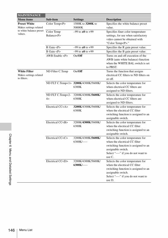
146
Chapter 6 M
enu and Detailed S
ettings
Preset WhiteMakes settings related to white balance preset values.
Color Temp<P> 1500K to 3200K to 50000K
Specifies the white balance preset value.
Color Temp Balance<P>
–99 to ±0 to +99 Specifies finer color temperature settings, for use when satisfactory video cannot be obtained with “Color Temp<P>.”
R Gain <P> –99 to ±0 to +99 Specifies the R gain preset value.
B Gain <P> –99 to ±0 to +99 Specifies the B gain preset value.
AWB Enable <P> On/Off Turns on and off execution of the AWB (auto white balance) function when the WHITE BAL switch is set to PRST.
White FilterMakes settings related to filters.
ND Filter C.Temp On/Off Turns the function that assigns electrical CC filters to ND filters on or off.
ND FLT C.Temp<1> 3200K/4300K/5600K/6300K
Selects the color temperature for when electrical CC filters are assigned to ND filters.
ND FLT C.Temp<2-4>
3200K/4300K/5600K/6300K
Selects the color temperature for when electrical CC filters are assigned to ND filters.
Electrical CC<A> 3200K/4300K/5600K/6300K
Selects the color temperature for when the electrical CC filter switching function is assigned to an assignable switch.
Electrical CC<B> 3200K/4300K/5600K/6300K
Selects the color temperature for when the electrical CC filter switching function is assigned to an assignable switch.
Electrical CC<C> 3200K/4300K/5600K/6300K/-----
Selects the color temperature for when the electrical CC filter switching function is assigned to an assignable switch.Select “----” if you do not want to use C.
Electrical CC<D> 3200K/4300K/5600K/6300K/-----
Selects the color temperature for when the electrical CC filter switching function is assigned to an assignable switch.Select “----” if you do not want to use D.
MAINTENANCEMenu items Sub-item Settings Description
Menu List
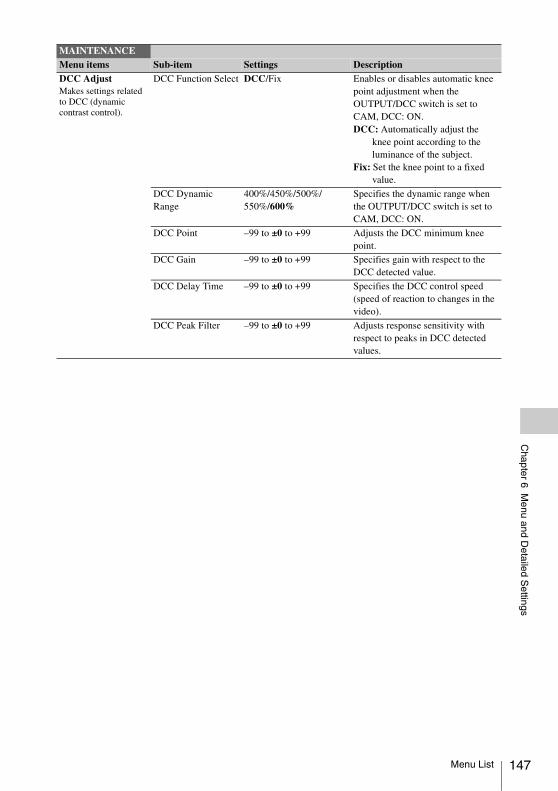
Chapter 6 M
enu and Detailed S
ettings
DCC AdjustMakes settings related to DCC (dynamic contrast control).
DCC Function Select DCC/Fix Enables or disables automatic knee point adjustment when the OUTPUT/DCC switch is set to CAM, DCC: ON.DCC: Automatically adjust the
knee point according to the luminance of the subject.
Fix: Set the knee point to a fixed value.
DCC Dynamic Range
400%/450%/500%/550%/600%
Specifies the dynamic range when the OUTPUT/DCC switch is set to CAM, DCC: ON.
DCC Point –99 to ±0 to +99 Adjusts the DCC minimum knee point.
DCC Gain –99 to ±0 to +99 Specifies gain with respect to the DCC detected value.
DCC Delay Time –99 to ±0 to +99 Specifies the DCC control speed (speed of reaction to changes in the video).
DCC Peak Filter –99 to ±0 to +99 Adjusts response sensitivity with respect to peaks in DCC detected values.
MAINTENANCEMenu items Sub-item Settings Description
Menu List 147
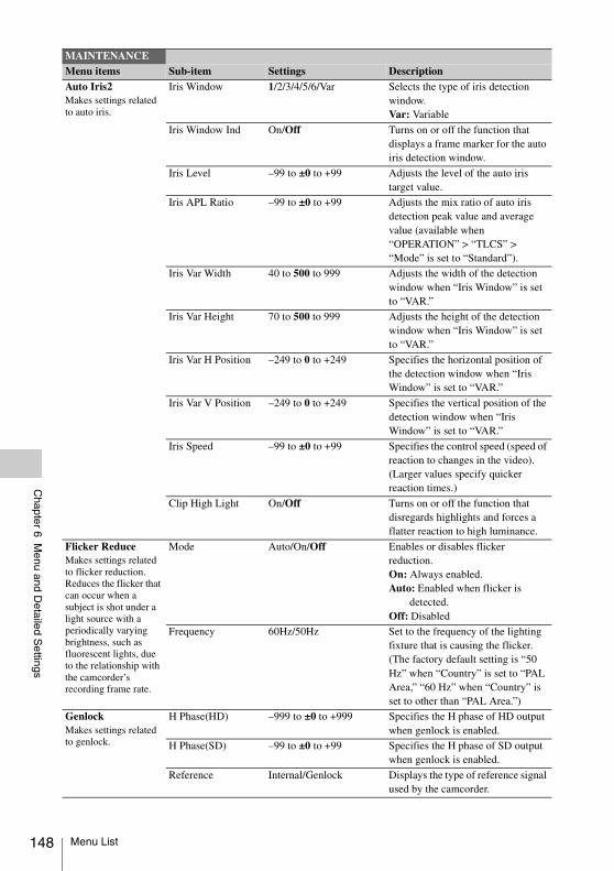
148
Chapter 6 M
enu and Detailed S
ettings
Auto Iris2Makes settings related to auto iris.
Iris Window 1/2/3/4/5/6/Var Selects the type of iris detection window. Var: Variable
Iris Window Ind On/Off Turns on or off the function that displays a frame marker for the auto iris detection window.
Iris Level –99 to ±0 to +99 Adjusts the level of the auto iris target value.
Iris APL Ratio –99 to ±0 to +99 Adjusts the mix ratio of auto iris detection peak value and average value (available when “OPERATION” > “TLCS” > “Mode” is set to “Standard”).
Iris Var Width 40 to 500 to 999 Adjusts the width of the detection window when “Iris Window” is set to “VAR.”
Iris Var Height 70 to 500 to 999 Adjusts the height of the detection window when “Iris Window” is set to “VAR.”
Iris Var H Position –249 to 0 to +249 Specifies the horizontal position of the detection window when “Iris Window” is set to “VAR.”
Iris Var V Position –249 to 0 to +249 Specifies the vertical position of the detection window when “Iris Window” is set to “VAR.”
Iris Speed –99 to ±0 to +99 Specifies the control speed (speed of reaction to changes in the video). (Larger values specify quicker reaction times.)
Clip High Light On/Off Turns on or off the function that disregards highlights and forces a flatter reaction to high luminance.
Flicker ReduceMakes settings related to flicker reduction.Reduces the flicker that can occur when a subject is shot under a light source with a periodically varying brightness, such as fluorescent lights, due to the relationship with the camcorder’s recording frame rate.
Mode Auto/On/Off Enables or disables flicker reduction.On: Always enabled.Auto: Enabled when flicker is
detected.Off: Disabled
Frequency 60Hz/50Hz Set to the frequency of the lighting fixture that is causing the flicker. (The factory default setting is “50 Hz” when “Country” is set to “PAL Area,” “60 Hz” when “Country” is set to other than “PAL Area.”)
GenlockMakes settings related to genlock.
H Phase(HD) –999 to ±0 to +999 Specifies the H phase of HD output when genlock is enabled.
H Phase(SD) –99 to ±0 to +99 Specifies the H phase of SD output when genlock is enabled.
Reference Internal/Genlock Displays the type of reference signal used by the camcorder.
MAINTENANCEMenu items Sub-item Settings Description
Menu List
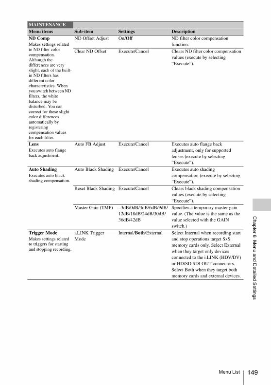
Chapter 6 M
enu and Detailed S
ettings
ND CompMakes settings related to ND filter color compensation. Although the differences are very slight, each of the built-in ND filters has different color characteristics. When you switch between ND filters, the white balance may be disturbed. You can correct for these slight color differences automatically by registering compensation values for each filter.
ND Offset Adjust On/Off ND filter color compensation function.
Clear ND Offset Execute/Cancel Clears ND filter color compensation values (execute by selecting “Execute”).
LensExecutes auto flange back adjustment.
Auto FB Adjust Execute/Cancel Executes auto flange back adjustment, only for supported lenses (execute by selecting “Execute”).
Auto ShadingExecutes auto black shading compensation.
Auto Black Shading Execute/Cancel Executes auto shading compensation (execute by selecting “Execute”).
Reset Black Shading Execute/Cancel Clears black shading compensation values (execute by selecting “Execute”).
Master Gain (TMP) –3dB/0dB/3dB/6dB/9dB/12dB/18dB/24dB/30dB/36dB/42dB
Specifies a temporary master gain value. (The value is the same as the value selected with the GAIN switch.)
Trigger ModeMakes settings related to triggers for starting and stopping recording.
i.LINK Trigger Mode
Internal/Both/External Select Internal when recording start and stop operations target SxS memory cards only. Select External when they target only devices connected to the i.LINK (HDV/DV) or HD/SD SDI OUT connectors. Select Both when they target both memory cards and external devices.
MAINTENANCEMenu items Sub-item Settings Description
Menu List 149
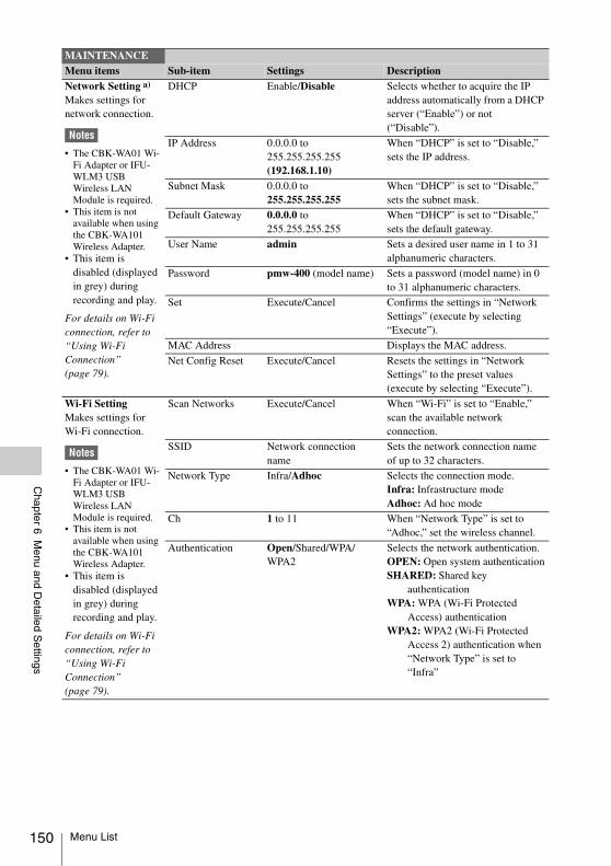
150
Chapter 6 M
enu and Detailed S
ettings
Network Setting a)
Makes settings for network connection.
Notes
• The CBK-WA01 Wi-Fi Adapter or IFU-WLM3 USB Wireless LAN Module is required.
• This item is not available when using the CBK-WA101 Wireless Adapter.
• This item is disabled (displayed in grey) during recording and play.
For details on Wi-Fi connection, refer to “Using Wi-Fi Connection” (page 79).
DHCP Enable/Disable Selects whether to acquire the IP address automatically from a DHCP server (“Enable”) or not (“Disable”).
IP Address 0.0.0.0 to 255.255.255.255 (192.168.1.10)
When “DHCP” is set to “Disable,” sets the IP address.
Subnet Mask 0.0.0.0 to 255.255.255.255
When “DHCP” is set to “Disable,” sets the subnet mask.
Default Gateway 0.0.0.0 to 255.255.255.255
When “DHCP” is set to “Disable,” sets the default gateway.
User Name admin Sets a desired user name in 1 to 31 alphanumeric characters.
Password pmw-400 (model name) Sets a password (model name) in 0 to 31 alphanumeric characters.
Set Execute/Cancel Confirms the settings in “Network Settings” (execute by selecting “Execute”).
MAC Address Displays the MAC address.
Net Config Reset Execute/Cancel Resets the settings in “Network Settings” to the preset values (execute by selecting “Execute”).
Wi-Fi SettingMakes settings for Wi-Fi connection.
Notes
• The CBK-WA01 Wi-Fi Adapter or IFU-WLM3 USB Wireless LAN Module is required.
• This item is not available when using the CBK-WA101 Wireless Adapter.
• This item is disabled (displayed in grey) during recording and play.
For details on Wi-Fi connection, refer to “Using Wi-Fi Connection” (page 79).
Scan Networks Execute/Cancel When “Wi-Fi” is set to “Enable,” scan the available network connection.
SSID Network connection name
Sets the network connection name of up to 32 characters.
Network Type Infra/Adhoc Selects the connection mode.Infra: Infrastructure modeAdhoc: Ad hoc mode
Ch 1 to 11 When “Network Type” is set to “Adhoc,” set the wireless channel.
Authentication Open/Shared/WPA/WPA2
Selects the network authentication.OPEN: Open system authenticationSHARED: Shared key
authenticationWPA: WPA (Wi-Fi Protected
Access) authenticationWPA2: WPA2 (Wi-Fi Protected
Access 2) authentication when “Network Type” is set to “Infra”
MAINTENANCEMenu items Sub-item Settings Description
Menu List
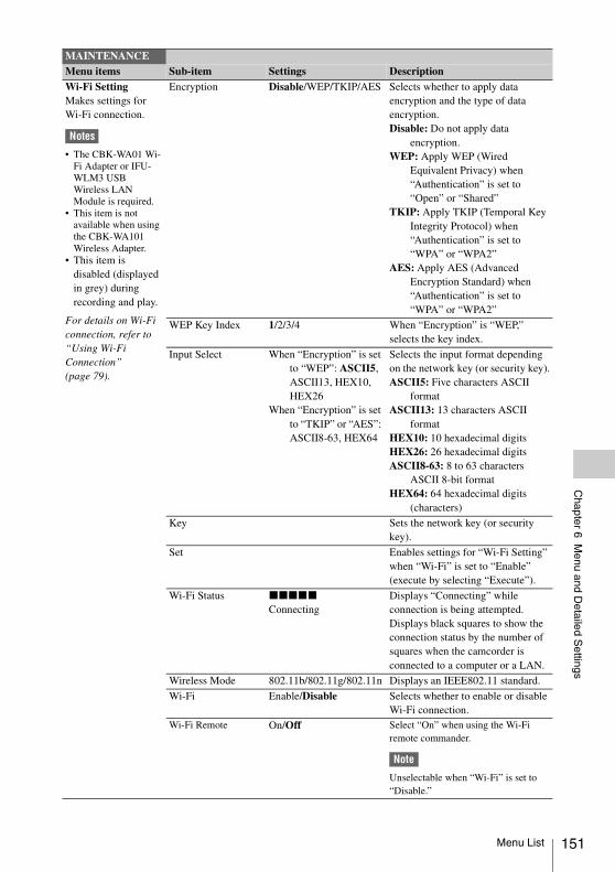
Chapter 6 M
enu and Detailed S
ettings
Wi-Fi SettingMakes settings for Wi-Fi connection.
Notes
• The CBK-WA01 Wi-Fi Adapter or IFU-WLM3 USB Wireless LAN Module is required.
• This item is not available when using the CBK-WA101 Wireless Adapter.
• This item is disabled (displayed in grey) during recording and play.
For details on Wi-Fi connection, refer to “Using Wi-Fi Connection” (page 79).
Encryption Disable/WEP/TKIP/AES Selects whether to apply data encryption and the type of data encryption.Disable: Do not apply data
encryption.WEP: Apply WEP (Wired
Equivalent Privacy) when “Authentication” is set to “Open” or “Shared”
TKIP: Apply TKIP (Temporal Key Integrity Protocol) when “Authentication” is set to “WPA” or “WPA2”
AES: Apply AES (Advanced Encryption Standard) when “Authentication” is set to “WPA” or “WPA2”
WEP Key Index 1/2/3/4 When “Encryption” is “WEP,” selects the key index.
Input Select When “Encryption” is set to “WEP”: ASCII5, ASCII13, HEX10, HEX26
When “Encryption” is set to “TKIP” or “AES”: ASCII8-63, HEX64
Selects the input format depending on the network key (or security key).ASCII5: Five characters ASCII
formatASCII13: 13 characters ASCII
formatHEX10: 10 hexadecimal digitsHEX26: 26 hexadecimal digitsASCII8-63: 8 to 63 characters
ASCII 8-bit formatHEX64: 64 hexadecimal digits
(characters)
Key Sets the network key (or security key).
Set Enables settings for “Wi-Fi Setting” when “Wi-Fi” is set to “Enable” (execute by selecting “Execute”).
Wi-Fi Status xxxxx
ConnectingDisplays “Connecting” while connection is being attempted. Displays black squares to show the connection status by the number of squares when the camcorder is connected to a computer or a LAN.
Wireless Mode 802.11b/802.11g/802.11n Displays an IEEE802.11 standard.
Wi-Fi Enable/Disable Selects whether to enable or disable Wi-Fi connection.
Wi-Fi Remote On/Off Select “On” when using the Wi-Fi remote commander.
Note
Unselectable when “Wi-Fi” is set to “Disable.”
MAINTENANCEMenu items Sub-item Settings Description
Menu List 151
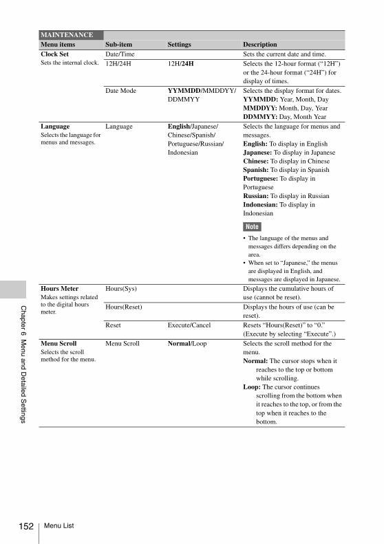
152
Chapter 6 M
enu and Detailed S
ettings
Clock SetSets the internal clock.
Date/Time Sets the current date and time.
12H/24H 12H/24H Selects the 12-hour format (“12H”) or the 24-hour format (“24H”) for display of times.
Date Mode YYMMDD/MMDDYY/DDMMYY
Selects the display format for dates. YYMMDD: Year, Month, DayMMDDYY: Month, Day, YearDDMMYY: Day, Month Year
LanguageSelects the language for menus and messages.
Language English/Japanese/Chinese/Spanish/Portuguese/Russian/Indonesian
Selects the language for menus and messages.English: To display in EnglishJapanese: To display in JapaneseChinese: To display in ChineseSpanish: To display in SpanishPortuguese: To display in PortugueseRussian: To display in RussianIndonesian: To display in Indonesian
Note
• The language of the menus and messages differs depending on the area.
• When set to “Japanese,” the menus are displayed in English, and messages are displayed in Japanese.
Hours MeterMakes settings related to the digital hours meter.
Hours(Sys) Displays the cumulative hours of use (cannot be reset).
Hours(Reset) Displays the hours of use (can be reset).
Reset Execute/Cancel Resets “Hours(Reset)” to “0.”(Execute by selecting “Execute”.)
Menu ScrollSelects the scroll method for the menu.
Menu Scroll Normal/Loop Selects the scroll method for the menu.Normal: The cursor stops when it
reaches to the top or bottom while scrolling.
Loop: The cursor continues scrolling from the bottom when it reaches to the top, or from the top when it reaches to the bottom.
MAINTENANCEMenu items Sub-item Settings Description
Menu List
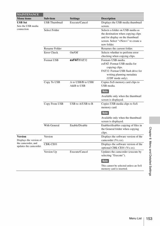
Chapter 6 M
enu and Detailed S
ettings
USB SetSets the USB media connection
USB Thumbnail Execute/Cancel Displays the USB media thumbnail screen.
Select Folder Selects a folder on USB media as the destination when copying clips and for display on the thumbnail screen. Select “<New>” to create a new folder.
Rename Folder Renames the current folder.
Error Check On/Off Selects whether to perform error checking when copying clips.
Format USB exFAT/FAT32 Formats USB media.exFAT: Format USB media for
copying clips.FAT32: Format USB flash drive for
writing planning metadata (UDF mode only).
Copy To USB A to USB/B to USB/A&B to USB
Copies SxS memory card clips to USB media.
Note
Available only when the thumbnail screen is displayed.
Copy From USB USB to A/USB to B Copies USB media clips to SxS memory card.
Note
Available only when the thumbnail screen is displayed.
With General Enable/Disable Enables/disables copying of files in the General folder when copying clips.
VersionDisplays the version of the camcorder, and updates the camcorder.
Version Displays the software version of the camcorder (Vx.xx).
CBK-CE01 Displays the software version of the optional CBK-CE01 (Vx.xx).
Version Up Execute/Cancel Updates the camcorder (execute by selecting “Execute”).
Note
This cannot be selected unless an SxS memory card is inserted.
MAINTENANCEMenu items Sub-item Settings Description
Menu List 153
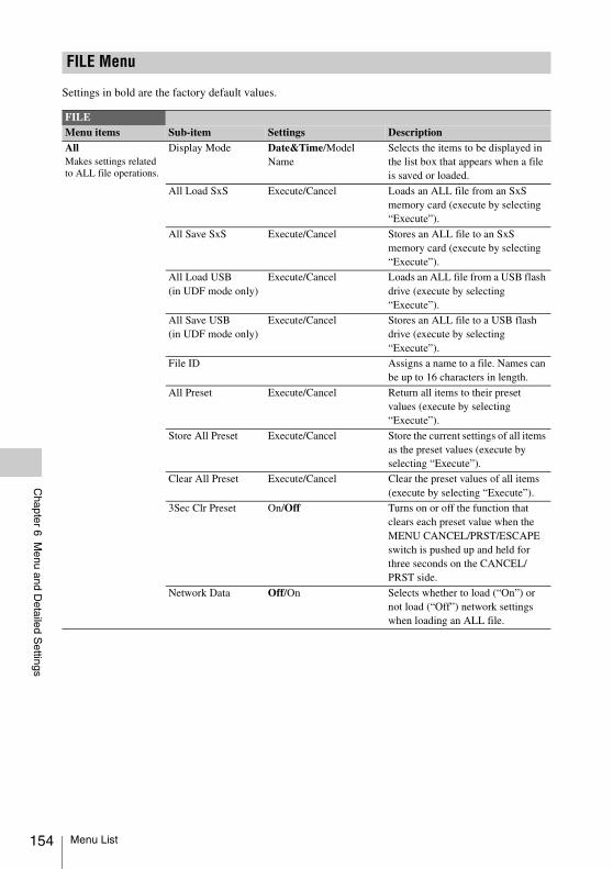
154
Chapter 6 M
enu and Detailed S
ettings
Settings in bold are the factory default values.
FILE Menu
FILEMenu items Sub-item Settings DescriptionAllMakes settings related to ALL file operations.
Display Mode Date&Time/Model Name
Selects the items to be displayed in the list box that appears when a file is saved or loaded.
All Load SxS Execute/Cancel Loads an ALL file from an SxS memory card (execute by selecting “Execute”).
All Save SxS Execute/Cancel Stores an ALL file to an SxS memory card (execute by selecting “Execute”).
All Load USB(in UDF mode only)
Execute/Cancel Loads an ALL file from a USB flash drive (execute by selecting “Execute”).
All Save USB(in UDF mode only)
Execute/Cancel Stores an ALL file to a USB flash drive (execute by selecting “Execute”).
File ID Assigns a name to a file. Names can be up to 16 characters in length.
All Preset Execute/Cancel Return all items to their preset values (execute by selecting “Execute”).
Store All Preset Execute/Cancel Store the current settings of all items as the preset values (execute by selecting “Execute”).
Clear All Preset Execute/Cancel Clear the preset values of all items (execute by selecting “Execute”).
3Sec Clr Preset On/Off Turns on or off the function that clears each preset value when the MENU CANCEL/PRST/ESCAPE switch is pushed up and held for three seconds on the CANCEL/PRST side.
Network Data Off/On Selects whether to load (“On”) or not load (“Off”) network settings when loading an ALL file.
Menu List
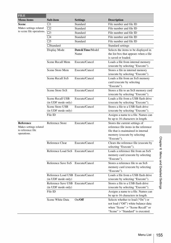
Chapter 6 M
enu and Detailed S
ettings
SceneMakes settings related to scene file operations.
s1 Standard File number and file ID
s2 Standard File number and file ID
s3 Standard File number and file ID
s4 Standard File number and file ID
s5 Standard File number and file ID
sStandard Standard settings
Display Mode Date&Time/Model Name
Selects the items to be displayed in the list box that appears when a file is saved or loaded.
Scene Recall Mem Execute/Cancel Loads a file from internal memory (execute by selecting “Execute”).
Scene Store Mem Execute/Cancel Stores a file in internal memory (execute by selecting “Execute”).
Scene Recall SxS Execute/Cancel Loads a file from an SxS memory card (execute by selecting “Execute”).
Scene Store SxS Execute/Cancel Stores a file to an SxS memory card (execute by selecting “Execute”).
Scene Recall USB(in UDF mode only)
Execute/Cancel Loads a file from a USB flash drive (execute by selecting “Execute”).
Scene Store USB(in UDF mode only)
Execute/Cancel Stores a file to a USB flash drive (execute by selecting “Execute”).
File ID Assigns a name to a file. Names can be up to 16 characters in length.
ReferenceMakes settings related to reference file operations.
Reference Store Execute/Cancel Stores the current settings of reference file items in the reference file that is maintained in internal memory (execute by selecting “Execute”).
Reference Clear Execute/Cancel Clears the reference file (execute by selecting “Execute”).
Reference Load SxS Execute/Cancel Loads a reference file from an SxS memory card (execute by selecting “Execute”).
Reference Save SxS Execute/Cancel Stores a reference file to an SxS memory card (execute by selecting “Execute”).
Reference Load USB(in UDF mode only)
Execute/Cancel Loads a file from a USB flash drive (execute by selecting “Execute”).
Reference Save USB(in UDF mode only)
Execute/Cancel Stores a file to a USB flash drive (execute by selecting “Execute”).
File ID Assigns a name to a file. Names can be up to 16 characters in length.
Scene White Data On/Off Selects whether to load (“On”) or not load (“Off”) white balance data when “Scene” > “Scene Recall” or “Scene” > “Standard” is executed.
FILEMenu items Sub-item Settings Description
Menu List 155
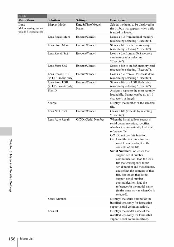
156
Chapter 6 M
enu and Detailed S
ettings
LensMakes settings related to lens file operations.
Display Mode Date&Time/Model Name
Selects the items to be displayed in the list box that appears when a file is saved or loaded.
Lens Recall Mem Execute/Cancel Loads a file from internal memory (execute by selecting “Execute”).
Lens Store Mem Execute/Cancel Stores a file in internal memory (execute by selecting “Execute”).
Lens Recall SxS Execute/Cancel Loads a file from an SxS memory card (execute by selecting “Execute”).
Lens Store SxS Execute/Cancel Stores a file to an SxS memory card (execute by selecting “Execute”).
Lens Recall USB(in UDF mode only)
Execute/Cancel Loads a file from a USB flash drive (execute by selecting “Execute”).
Lens Store USB(in UDF mode only)
Execute/Cancel Stores a file to a USB flash drive (execute by selecting “Execute”).
File ID Assigns a name to the most recently loaded file. Names can be up to 16 characters in length.
Source Displays the number of the selected file.
Lens No Offset Execute/Cancel Clears a file (execute by selecting “Execute”).
Lens Auto Recall Off/On/Serial Number When the installed lens supports serial communication, specifies whether to automatically load that reference file. Off: Do not use this function.On: Load the reference for the
model name and reflect the contents of the file.
Serial Number: For lenses that support serial number communication, load the lens file that corresponds to the serial number and model name, and reflect the contents of that file. For lenses that do not support serial number communication, load the reference for the model name (in the same way as when On is selected).
Serial Number Displays the serial number of the installed lens (only for lenses that support serial communication).
Lens ID Displays the model name of the installed lens (only for lenses that support serial communication).
FILEMenu items Sub-item Settings Description
Menu List
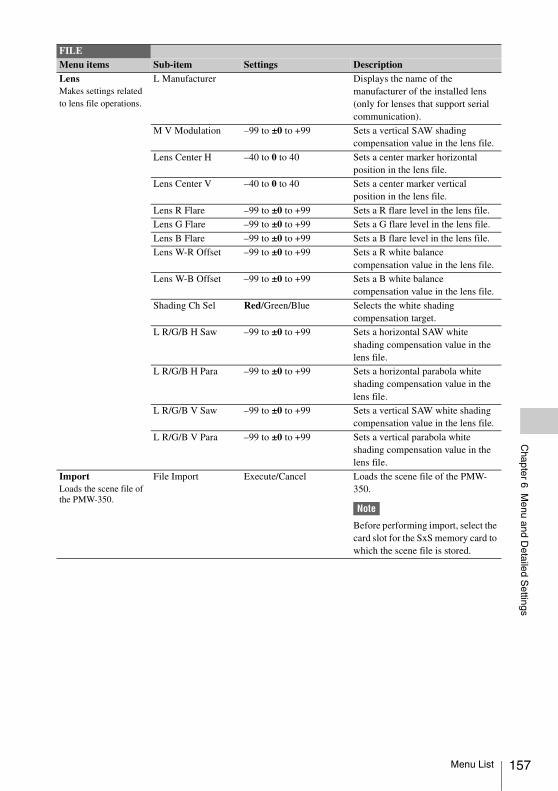
Chapter 6 M
enu and Detailed S
ettings
LensMakes settings related to lens file operations.
L Manufacturer Displays the name of the manufacturer of the installed lens (only for lenses that support serial communication).
M V Modulation –99 to ±0 to +99 Sets a vertical SAW shading compensation value in the lens file.
Lens Center H –40 to 0 to 40 Sets a center marker horizontal position in the lens file.
Lens Center V –40 to 0 to 40 Sets a center marker vertical position in the lens file.
Lens R Flare –99 to ±0 to +99 Sets a R flare level in the lens file.
Lens G Flare –99 to ±0 to +99 Sets a G flare level in the lens file.
Lens B Flare –99 to ±0 to +99 Sets a B flare level in the lens file.
Lens W-R Offset –99 to ±0 to +99 Sets a R white balance compensation value in the lens file.
Lens W-B Offset –99 to ±0 to +99 Sets a B white balance compensation value in the lens file.
Shading Ch Sel Red/Green/Blue Selects the white shading compensation target.
L R/G/B H Saw –99 to ±0 to +99 Sets a horizontal SAW white shading compensation value in the lens file.
L R/G/B H Para –99 to ±0 to +99 Sets a horizontal parabola white shading compensation value in the lens file.
L R/G/B V Saw –99 to ±0 to +99 Sets a vertical SAW white shading compensation value in the lens file.
L R/G/B V Para –99 to ±0 to +99 Sets a vertical parabola white shading compensation value in the lens file.
ImportLoads the scene file of the PMW-350.
File Import Execute/Cancel Loads the scene file of the PMW-350.
Note
Before performing import, select the card slot for the SxS memory card to which the scene file is stored.
FILEMenu items Sub-item Settings Description
Menu List 157
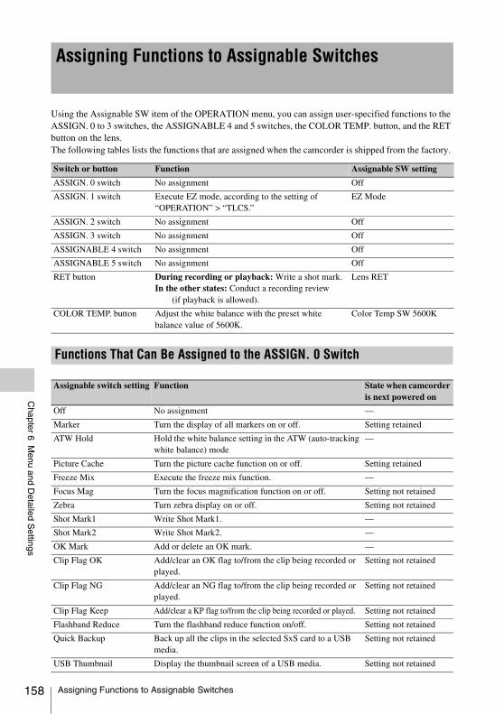
158
Chapter 6 M
enu and Detailed S
ettings
Using the Assignable SW item of the OPERATION menu, you can assign user-specified functions to the ASSIGN. 0 to 3 switches, the ASSIGNABLE 4 and 5 switches, the COLOR TEMP. button, and the RET button on the lens. The following tables lists the functions that are assigned when the camcorder is shipped from the factory.
Assigning Functions to Assignable Switches
Switch or button Function Assignable SW setting
ASSIGN. 0 switch No assignment Off
ASSIGN. 1 switch Execute EZ mode, according to the setting of “OPERATION” > “TLCS.”
EZ Mode
ASSIGN. 2 switch No assignment Off
ASSIGN. 3 switch No assignment Off
ASSIGNABLE 4 switch No assignment Off
ASSIGNABLE 5 switch No assignment Off
RET button During recording or playback: Write a shot mark.In the other states: Conduct a recording review
(if playback is allowed).
Lens RET
COLOR TEMP. button Adjust the white balance with the preset white balance value of 5600K.
Color Temp SW 5600K
Functions That Can Be Assigned to the ASSIGN. 0 Switch
Assignable switch setting Function State when camcorder is next powered on
Off No assignment —
Marker Turn the display of all markers on or off. Setting retained
ATW Hold Hold the white balance setting in the ATW (auto-tracking white balance) mode
—
Picture Cache Turn the picture cache function on or off. Setting retained
Freeze Mix Execute the freeze mix function. —
Focus Mag Turn the focus magnification function on or off. Setting not retained
Zebra Turn zebra display on or off. Setting not retained
Shot Mark1 Write Shot Mark1. —
Shot Mark2 Write Shot Mark2. —
OK Mark Add or delete an OK mark. —
Clip Flag OK Add/clear an OK flag to/from the clip being recorded or played.
Setting not retained
Clip Flag NG Add/clear an NG flag to/from the clip being recorded or played.
Setting not retained
Clip Flag Keep Add/clear a KP flag to/from the clip being recorded or played. Setting not retained
Flashband Reduce Turn the flashband reduce function on/off. Setting not retained
Quick Backup Back up all the clips in the selected SxS card to a USB media.
Setting not retained
USB Thumbnail Display the thumbnail screen of a USB media. Setting not retained
Assigning Functions to Assignable Switches
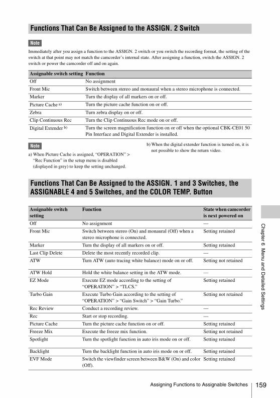
Chapter 6 M
enu and Detailed S
ettings
Note
Immediately after you assign a function to the ASSIGN. 2 switch or you switch the recording format, the setting of the switch at that point may not match the camcorder’s internal state. After assigning a function, switch the ASSIGN. 2 switch or power the camcorder off and on again.
Note
a) When Picture Cache is assigned, “OPERATION” > “Rec Function” in the setup menu is disabled (displayed in grey) to keep the setting unchanged.
b) When the digital extender function is turned on, it is not possible to show the return video.
Functions That Can Be Assigned to the ASSIGN. 2 Switch
Assignable switch setting Function
Off No assignment
Front Mic Switch between stereo and monaural when a stereo microphone is connected.
Marker Turn the display of all markers on or off.
Picture Cache a) Turn the picture cache function on or off.
Zebra Turn zebra display on or off.
Clip Continuous Rec Turn the Clip Continuous Rec mode on or off.
Digital Extender b) Turn the screen magnification function on or off when the optional CBK-CE01 50 Pin Interface and Digital Extender is installed.
Functions That Can Be Assigned to the ASSIGN. 1 and 3 Switches, the ASSIGNABLE 4 and 5 Switches, and the COLOR TEMP. Button
Assignable switch setting
Function State when camcorder is next powered on
Off No assignment —
Front Mic Switch between stereo (On) and monaural (Off) when a stereo microphone is connected.
Setting retained
Marker Turn the display of all markers on or off. Setting retained
Last Clip Delete Delete the most recently recorded clip. —
ATW Turn ATW (auto tracing white balance) mode on or off. Setting not retained
ATW Hold Hold the white balance setting in the ATW mode. —
EZ Mode Execute EZ mode according to the setting of “OPERATION” > “TLCS.”
Setting retained
Turbo Gain Execute Turbo Gain according to the setting of “OPERATION” > “Gain Switch” > “Gain Turbo.”
Setting not retained
Rec Review Conduct a recording review. —
Rec Start or stop recording. —
Picture Cache Turn the picture cache function on or off. Setting retained
Freeze Mix Execute the freeze mix function. Setting not retained
Spotlight Turn the spotlight function in auto iris mode on or off. Setting retained
Backlight Turn the backlight function in auto iris mode on or off. Setting retained
EVF Mode Switch the viewfinder screen between B&W (On) and color (Off).
Setting retained
Assigning Functions to Assignable Switches 159
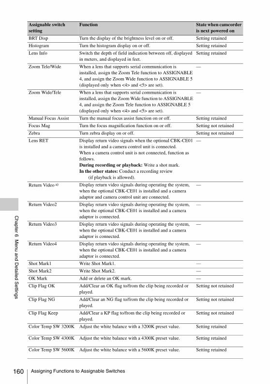
160
Chapter 6 M
enu and Detailed S
ettings
BRT Disp Turn the display of the brightness level on or off. Setting retained
Histogram Turn the histogram display on or off. Setting retained
Lens Info Switch the depth of field indication between off, displayed in meters, and displayed in feet.
Setting retained
Zoom Tele/Wide When a lens that supports serial communication is installed, assign the Zoom Tele function to ASSIGNABLE 4, and assign the Zoom Wide function to ASSIGNABLE 5 (displayed only when <4> and <5> are set).
—
Zoom Wide/Tele When a lens that supports serial communication is installed, assign the Zoom Wide function to ASSIGNABLE 4, and assign the Zoom Tele function to ASSIGNABLE 5 (displayed only when <4> and <5> are set).
—
Manual Focus Assist Turn the manual focus assist function on or off. Setting retained
Focus Mag Turn the focus magnification function on or off. Setting not retained
Zebra Turn zebra display on or off. Setting not retained
Lens RET Display return video signals when the optional CBK-CE01 is installed and a camera control unit is connected.When a camera control unit is not connected, function as follows.During recording or playback: Write a shot mark.In the other states: Conduct a recording review
(if playback is allowed).
—
Return Video a) Display return video signals during operating the system, when the optional CBK-CE01 is installed and a camera adaptor and camera control unit are connected.
—
Return Video2 Display return video signals during operating the system, when the optional CBK-CE01 is installed and a camera adaptor is connected.
—
Return Video3 Display return video signals during operating the system, when the optional CBK-CE01 is installed and a camera adaptor is connected.
—
Return Video4 Display return video signals during operating the system, when the optional CBK-CE01 is installed and a camera adaptor is connected.
—
Shot Mark1 Write Shot Mark1. —
Shot Mark2 Write Shot Mark2. —
OK Mark Add or delete an OK mark. —
Clip Flag OK Add/Clear an OK flag to/from the clip being recorded or played.
Setting not retained
Clip Flag NG Add/Clear an NG flag to/from the clip being recorded or played.
Setting not retained
Clip Flag Keep Add/Clear a KP flag to/from the clip being recorded or played.
Setting not retained
Color Temp SW 3200K Adjust the white balance with a 3200K preset value. Setting retained
Color Temp SW 4300K Adjust the white balance with a 4300K preset value. Setting retained
Color Temp SW 5600K Adjust the white balance with a 5600K preset value. Setting retained
Assignable switch setting
Function State when camcorder is next powered on
Assigning Functions to Assignable Switches
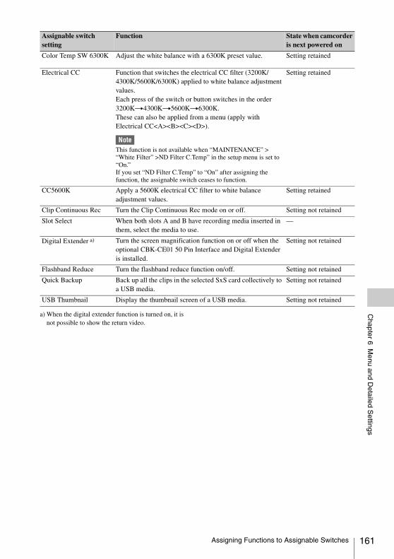
Chapter 6 M
enu and Detailed S
ettings
a) When the digital extender function is turned on, it is not possible to show the return video.
Color Temp SW 6300K Adjust the white balance with a 6300K preset value. Setting retained
Electrical CC Function that switches the electrical CC filter (3200K/4300K/5600K/6300K) applied to white balance adjustment values.Each press of the switch or button switches in the order 3200Kt4300Kt5600Kt6300K.These can also be applied from a menu (apply with Electrical CC<A><B><C><D>).
NoteThis function is not available when “MAINTENANCE” > “White Filter” >ND Filter C.Temp” in the setup menu is set to “On.”If you set “ND Filter C.Temp” to “On” after assigning the function, the assignable switch ceases to function.
Setting retained
CC5600K Apply a 5600K electrical CC filter to white balance adjustment values.
Setting retained
Clip Continuous Rec Turn the Clip Continuous Rec mode on or off. Setting not retained
Slot Select When both slots A and B have recording media inserted in them, select the media to use.
—
Digital Extender a) Turn the screen magnification function on or off when the optional CBK-CE01 50 Pin Interface and Digital Extender is installed.
Setting not retained
Flashband Reduce Turn the flashband reduce function on/off. Setting not retained
Quick Backup Back up all the clips in the selected SxS card collectively to a USB media.
Setting not retained
USB Thumbnail Display the thumbnail screen of a USB media. Setting not retained
Assignable switch setting
Function State when camcorder is next powered on
Assigning Functions to Assignable Switches 161
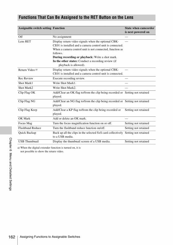
162
Chapter 6 M
enu and Detailed S
ettings
a) When the digital extender function is turned on, it is not possible to show the return video.
Functions That Can Be Assigned to the RET Button on the Lens
Assignable switch setting Function State when camcorder is next powered on
Off No assignment —
Lens RET Display return video signals when the optional CBK-CE01 is installed and a camera control unit is connected.When a camera control unit is not connected, function as follows.During recording or playback: Write a shot mark.In the other states: Conduct a recording review (if
playback is allowed).
—
Return Video a) Display return video signals when the optional CBK-CE01 is installed and a camera control unit is connected.
—
Rec Review Execute recording review. —
Shot Mark1 Write Shot Mark1. —
Shot Mark2 Write Shot Mark2. —
Clip Flag OK Add/Clear an OK flag to/from the clip being recorded or played.
Setting not retained
Clip Flag NG Add/Clear an NG flag to/from the clip being recorded or played.
Setting not retained
Clip Flag Keep Add/Clear a KP flag to/from the clip being recorded or played.
Setting not retained
OK Mark Add or delete an OK mark. —
Focus Mag Turn the focus magnification function on or off. Setting not retained
Flashband Reduce Turn the flashband reduce function on/off. Setting not retained
Quick Backup Back up all the clips in the selected SxS card collectively to a USB media.
Setting not retained
USB Thumbnail Display the thumbnail screen of a USB media. Setting not retained
Assigning Functions to Assignable Switches
Chapter 7 S
aving and Loading User S
etting Data
You can save setup menu settings in the camcorder’s internal memory, on an SxS memory card, or USB flash drive (in UDF/exFAT mode). This allows you to quickly recall an appropriate set of menu settings for the current situation.Setting data is saved in the following categories.ALL files: ALL files save the setting data of all
menus. You can save up to 64 ALL files on an SxS memory card or USB flash drive (in UDF/exFAT mode).
Note
Device specific data (shading, output levels, and other data that requires adjustment for the specific device) is not saved.
Scene files: Scene file save adjustments to PAINT menu items for the purpose of shooting a particular scene. You can save up to five scene files in the camcorder’s internal memory and up to 64 scene files on an SxS memory card or USB flash drive (in UDF/exFAT mode).
Reference files: Reference files save the reference values that are set when you execute “FILE” > “Scene” > “Standard” in the setup menu. You can save one reference file in the camcorder’s internal memory and one on an SxS memory card or USB flash drive (in UDF/exFAT mode).
Lens files: Lens files save the setting data used to compensate for lens characteristics, such as flare, white shading, white balance and center markers. You can save up to 32 lens files in the camcorder’s internal memory and up to 64 lens files on an SxS memory card or USB flash drive (in UDF/exFAT mode).
The first settings stored in a file are called “preset” values.Even after loading files to set up the camcorder, and overwriting original files with new settings,
you can still recover preset values and reset files to their initial states (see page 165).
Before starting, insert a writable SxS memory card into a memory card slot.
See “Basic Setup Menu Operations” (page 110) for information about menu operations.
1 Select “FILE” > “All” in the setup menu.
To assign a name to the data before saving itAssign a name before proceeding to step 2.
For details, see “To assign names to files” (page 164).
2 Select “All Save SxS” > “Execute.”An ALL file list box appears.File numbers where “No File” is displayed are empty file numbers. File numbers with a file name or a date and time are the number of files that already contain data.
3 Turn the MENU knob to select the desired file number.
4 Press the MENU knob.A confirmation message appears.
5 To execute the save, select “Execute,” and then press the MENU knob.To cancel the save, select “Cancel,” and then press the MENU knob.If you choose to execute the save, the ACCESS lamp lights (in blue on the right-side panel and in orange in the card slot section). A completion message appears and the ACCESS lamp goes out when the data has been saved to the SxS memory card.
If an error message appearsOne of the following error messages may appear during execution of the save, or as soon as you
Chapter7 Saving and Loading User Setting Data
Saving and Loading Settings Saving Setting Data
Saving and Loading Settings 163
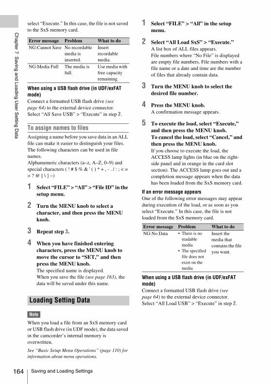
164
Chapter 7 S
aving and Loading User S
etting Data
select “Execute.” In this case, the file is not saved to the SxS memory card.
When using a USB flash drive (in UDF/exFAT mode)Connect a formatted USB flash drive (see page 64) to the external device connector.Select “All Save USB” > “Execute” in step 2.
To assign names to filesAssigning a name before you save data in an ALL file can make it easier to distinguish your files.The following characters can be used in file names.Alphanumeric characters (a–z, A–Z, 0–9) and special characters ( ! # $ % & ' ( ) * + , - . / : ; < = > ? @ [ \ ] ~)
1 Select “FILE” > “All” > “File ID” in the setup menu.
2 Turn the MENU knob to select a character, and then press the MENU knob.
3 Repeat step 3.
4 When you have finished entering characters, press the MENU knob to move the cursor to “SET,” and then press the MENU knob.The specified name is displayed.When you save the file (see page 163), the data will be saved under this name.
Note
When you load a file from an SxS memory card or USB flash drive (in UDF mode), the data saved in the camcorder’s internal memory is overwritten.
See “Basic Setup Menu Operations” (page 110) for information about menu operations.
1 Select “FILE” > “All” in the setup menu.
2 Select “All Load SxS” > “Execute.”A list box of ALL files appears.File numbers where “No File” is displayed are empty file numbers. File numbers with a file name or a date and time are the number of files that already contain data.
3 Turn the MENU knob to select the desired file number.
4 Press the MENU knob.A confirmation message appears.
5 To execute the load, select “Execute,” and then press the MENU knob.To cancel the load, select “Cancel,” and then press the MENU knob.If you choose to execute the load, the ACCESS lamp lights (in blue on the right-side panel and in orange in the card slot section). The ACCESS lamp goes out and a completion message appears when the data has been loaded from the SxS memory card.
If an error message appearsOne of the following error messages may appear during execution of the load, or as soon as you select “Execute.” In this case, the file is not loaded from the SxS memory card.
When using a USB flash drive (in UDF/exFAT mode)Connect a formatted USB flash drive (see page 64) to the external device connector.Select “All Load USB” > “Execute” in step 2.
Error message Problem What to doNG:Cannot Save No recordable
media is inserted.
Insert recordable media.
NG:Media Full The media is full.
Use media with free capacity remaining.
Loading Setting Data
Error message Problem What to doNG:No Data • There is no
readable media
• The specified file does not exist on the media
Insert the media that contains the file you want.
Saving and Loading Settings
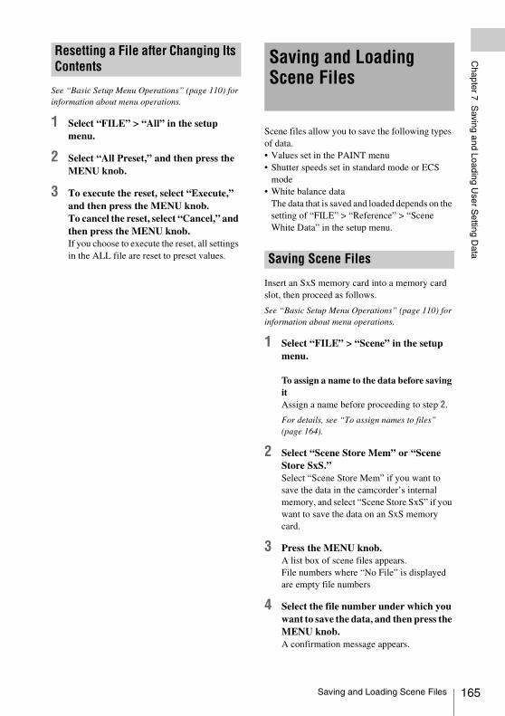
Chapter 7 S
aving and Loading User S
etting Data
See “Basic Setup Menu Operations” (page 110) for information about menu operations.
1 Select “FILE” > “All” in the setup menu.
2 Select “All Preset,” and then press the MENU knob.
3 To execute the reset, select “Execute,” and then press the MENU knob.To cancel the reset, select “Cancel,” and then press the MENU knob.If you choose to execute the reset, all settings in the ALL file are reset to preset values.
Scene files allow you to save the following types of data.• Values set in the PAINT menu• Shutter speeds set in standard mode or ECS
mode• White balance data
The data that is saved and loaded depends on the setting of “FILE” > “Reference” > “Scene White Data” in the setup menu.
Insert an SxS memory card into a memory card slot, then proceed as follows.
See “Basic Setup Menu Operations” (page 110) for information about menu operations.
1 Select “FILE” > “Scene” in the setup menu.
To assign a name to the data before saving itAssign a name before proceeding to step 2.
For details, see “To assign names to files” (page 164).
2 Select “Scene Store Mem” or “Scene Store SxS.”Select “Scene Store Mem” if you want to save the data in the camcorder’s internal memory, and select “Scene Store SxS” if you want to save the data on an SxS memory card.
3 Press the MENU knob.A list box of scene files appears.File numbers where “No File” is displayed are empty file numbers
4 Select the file number under which you want to save the data, and then press the MENU knob.A confirmation message appears.
Resetting a File after Changing Its Contents Saving and Loading
Scene Files
Saving Scene Files
Saving and Loading Scene Files 165
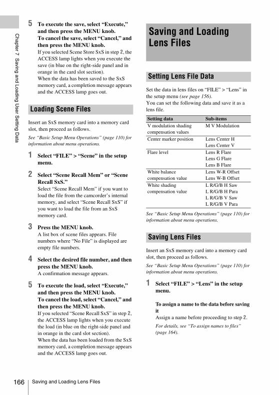
166
Chapter 7 S
aving and Loading User S
etting Data
5 To execute the save, select “Execute,” and then press the MENU knob.To cancel the save, select “Cancel,” and then press the MENU knob.If you selected Scene Store SxS in step 2, the ACCESS lamp lights when you execute the save (in blue on the right-side panel and in orange in the card slot section).When the data has been saved to the SxS memory card, a completion message appears and the ACCESS lamp goes out.
Insert an SxS memory card into a memory card slot, then proceed as follows.
See “Basic Setup Menu Operations” (page 110) for information about menu operations.
1 Select “FILE” > “Scene” in the setup menu.
2 Select “Scene Recall Mem” or “Scene Recall SxS.”Select “Scene Recall Mem” if you want to load the file from the camcorder’s internal memory, and select “Scene Recall SxS” if you want to load the file from an SxS memory card.
3 Press the MENU knob.A list box of scene files appears. File numbers where “No File” is displayed are empty file numbers.
4 Select the desired file number, and then press the MENU knob.A confirmation message appears.
5 To execute the load, select “Execute,” and then press the MENU knob.To cancel the load, select “Cancel,” and then press the MENU knob.If you selected “Scene Recall SxS” in step 2, the ACCESS lamp lights when you execute the load (in blue on the right-side panel and in orange in the card slot section).When the data has been loaded from the SxS memory card, a completion message appears and the ACCESS lamp goes out.
Set the data in lens files on “FILE” > “Lens” in the setup menu (see page 156).You can set the following data and save it as a lens file.
See “Basic Setup Menu Operations” (page 110) for information about menu operations.
Insert an SxS memory card into a memory card slot, then proceed as follows.
See “Basic Setup Menu Operations” (page 110) for information about menu operations.
1 Select “FILE” > “Lens” in the setup menu.
To assign a name to the data before saving itAssign a name before proceeding to step 2.
For details, see “To assign names to files” (page 164).
Loading Scene Files
Saving and Loading Lens Files
Setting Lens File Data
Setting data Sub-itemsV modulation shading compensation values
M V Modulation
Center marker position Lens Center HLens Center V
Flare level Lens R FlareLens G FlareLens B Flare
White balance compensation value
Lens W-R OffsetLens W-B Offset
White shading compensation value
L R/G/B H SawL R/G/B H ParaL R/G/B V SawL R/G/B V Para
Saving Lens Files
Saving and Loading Lens Files
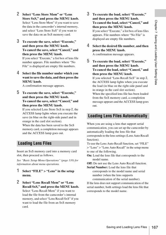
Chapter 7 S
aving and Loading User S
etting Data
2 Select “Lens Store Mem” or “Lens Store SxS,” and press the MENU knob.Select “Lens Store Mem” if you want to save the data in the camcorder’s internal memory, and select “Lens Store SxS” if you want to save the data on an SxS memory card.
3 To execute the save, select “Execute,” and then press the MENU knob.To cancel the save, select “Cancel,” and then press the MENU knob.If you select “Execute,” a list box of lens file number appears. File numbers where “No File” is displayed are empty file numbers.
4 Select the file number under which you want to save the data, and then press the MENU knob.A confirmation message appears.
5 To execute the save, select “Execute,” and then press the MENU knob.To cancel the save, select “Cancel,” and then press the MENU knob.If you selected Lens Store SxS in step 2, the ACCESS lamp lights when you execute the save (in blue on the right-side panel and in orange in the card slot section).When the data has been saved to the SxS memory card, a completion message appears and the ACCESS lamp goes out.
Insert an SxS memory card into a memory card slot, then proceed as follows.
See “Basic Setup Menu Operations” (page 110) for information about menu operations.
1 Select “FILE” > “Lens” in the setup menu.
2 Select “Lens Recall Mem” or “Lens Recall SxS,” and press the MENU knob.Select “Lens Recall Mem” if you want to load the file from the camcorder’s internal memory, and select “Lens Recall SxS” if you want to load the file from an SxS memory card.
3 To execute the load, select “Execute,” and then press the MENU knob.To cancel the load, select “Cancel,” and then press the MENU knob.If you select “Execute,” a list box of lens files appears. File numbers where “No File” is displayed are empty file numbers.
4 Select the desired file number, and then press the MENU knob.A confirmation message appears.
5 To execute the load, select “Execute,” and then press the MENU knob.To cancel the load, select “Cancel,” and then press the MENU knob.If you selected “Lens Recall SxS” in step 2, the ACCESS lamp lights when you execute the load (in blue on the right-side panel and in orange in the card slot section).When the specified lens file has been loaded from the SxS memory card, a completion message appears and the ACCESS lamp goes out.
When you are using a lens that support serial communication, you can set up the camcorder by automatically loading the lens file that corresponds to the lens settings (Lens Auto Recall function).To use the Lens Auto Recall function, set “FILE” > “Lens” > “Lens Auto Recall” in the setup menu to one of the following.On: Load the lens file that corresponds to the
model name.Off: Do not use the Lens Auto Recall function.Serial Number: Load the lens file that
corresponds to the model name and serial number (when the lens supports communication of the serial number).
If the lens does not support communication of the serial number, both settings load the lens file that corresponds to the model name.
Loading Lens Files
Loading Lens Files Automatically
Saving and Loading Lens Files 167
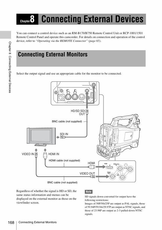
168
Chapter 8 C
onnecting External D
evices
You can connect a control device such as an RM-B170/B750 Remote Control Unit or RCP-1001/1501 Remote Control Panel and operate this camcorder. For details on connection and operation of the control device, refer to “Operating via the REMOTE Connector” (page 65).
Select the output signal and use an appropriate cable for the monitor to be connected.
Regardless of whether the signal is HD or SD, the same status information and menus can be displayed on the external monitor as those on the viewfinder screen.
Note
SD signals down-converted for output have the following restrictions:Images of 50P/50i/25P are output as PAL signals, those of 59.94P/59.94i/29.97P are output as NTSC signals, and those of 23.98P are output as 2-3 pulled-down NTSC signals.
Chapter8 Connecting External Devices
Connecting External Monitors
HDMI cable (not supplied)
BNC cable (not supplied)
BNC cable (not supplied)
Connecting External Monitors
Chapter 8 C
onnecting External D
evices
HD/SD SDI OUT connectors (BNC)The PMW-400 has two HD/SD SDI OUT connectors.You can connect a monitor or switcher, or recording device such as a VTR, etc., that supports SDI.The output from these connectors can be turned on and off with “OPERATION” > “Input/Output” > “SDI Output” in the setup menu (see page 115).For connection, use a BNC cable (not supplied).
HDMI connectorYou can connect a monitor or recording device such as a VTR, etc., that supports HDMI.The output from this connector can be turned on and off with “OPERATION” > “Input/Output” > “HDMI Output” in the setup menu (see page 115).For connection, use an HDMI cable (not supplied).
VIDEO OUT connectorYou can connect a monitor or recording device such as a VTR, etc., that supports analog composite signals.The analog composite signal output from this connector is the same as the NTSC or PAL encoded signal that is output from the HD/SD SDI OUT connector when the setting of output is SD signal (you can switch between NTSC and PAL with “OPERATION” > “Format” > “Country” in the setup menu (see page 113)).To input the VIDEO OUT connector output signal to an external analog composite device, it may be necessary to change the input signal setting of that external device to be matched with the analog composite signal setting for the VIDEO OUT connector.To input camcorder output audio to an external device such as a monitor or VTR or other recording device, connect the audio output of the AUDIO OUT connector to the audio input of that external device.For connection, use a BNC cable (not supplied).
i.LINK (HDV/DV) connectorThe i.LINK (HDV/DV) connector supports HDV and DV input/output. However, DV streams cannot be recorded on this camcorder.This connector can be used to connect a device that supports i.LINK (HDV). The device type can be a monitor, read/write device such as VTR or HDD, or computer.
To input/output HDV signalsHDV input/output is supported when the video format is an HDV compatible format (SP 1440/59.94i, SP 1440/50i, or SP 1440/23.98P), “OPERATION” > “Input/Output” > “Output&i.LINK” in the setup menu is set to “HD&HDV” or “SD&HDV,” and “Input/Output” > “i.LINK I/O” is set to “Enable.”When the video format is SP 1440/23.98P, a 59.94i HDV signal subjected to 2-3 pulldown processing is output.
To input/output DV signalsDV input/output is supported under either of the following conditions.• “OPERATION” > “Input/Output” >
“i.LINK I/O” in the setup menu is set to “Enable” on SD mode.
• On HD mode, the video format is other than DV incompatible formats (HQ 1920/23.98P, HQ 1440/23.98P, and HQ 1280/23.98P), “OPERATION” > “Input/Output” > “Output&i.LINK” in the setup menu is set to “SD&DV,” and “Input/Output” > “i.LINK I/O” is set to “Enable.”
Connecting External Monitors 169
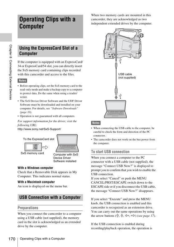
170
Chapter 8 C
onnecting External D
evices
If the computer is equipped with an ExpressCard/34 or ExpressCard/54 slot, you can directly insert the SxS memory card containing clips recorded with this camcorder and access to the files.
Notes
• Before operating clips, set the SxS memory card to the read-only mode and make a backup copy to a computer to protect data. Do the same when using a reader/writer.
• The SxS Device Driver Software and the UDF Driver Software must be downloaded and installed on your computer. For details, see “Software Downloads” (page 10).
• Operation is not guaranteed with all computers.
For support information for the driver, visit the following URL: http://www.sony.net/SxS-Support/
With a Windows computerCheck that a Removable Disk appears in My Computer. This indicates normal status.
With a Macintosh computerAn icon is displayed on the menu bar.
PreparationsWhen you connect the camcorder to a computer using a USB cable (not supplied), the memory card in the slot is acknowledged as an extended drive by the computer.
When two memory cards are mounted in this camcorder, they are acknowledged as two independent extended drives by the computer.
Notes
• When connecting the USB cable to the computer, be careful to check the form and direction of the PC connector.
• The camcorder does not work on the bus power from the computer.
To start USB connectionWhen you connect a computer to the PC connector with a USB cable (not supplied), the message “Connect USB Now?” is displayed to prompt you to confirm that you wish to enable the USB connection.If you select “Cancel” or push the MENU CANCEL/PRST/ESCAPE switch down to the ESCAPE side or if you disconnect the USB cable, the message “Connect USB Now?” disappears.
If you select “Execute” and press the MENU knob, the USB connection is enabled and this camcorder is recognized as an extension drive. You can carry out the same operations by using the arrow buttons (J, j, K, k) (see page 17).
If the USB connection is enabled during recording/playback operation, the operation is
Operating Clips with a Computer
Using the ExpressCard Slot of a Computer
USB Connection with a Computer
SxS PRO 8GB
To the ExpressCard slot
SxS memory card Computer with SxS Device Driver Software installed
USB cable (not supplied)
Operating Clips with a Computer
Chapter 8 C
onnecting External D
evices
stopped and the message “USB Connecting” appears on the viewfinder screen.At this time, the output signal from the VIDEO OUT connector, HDMI connector, and HD/SD SDI OUT connector changes to a black signal.
Notes
• The camcorder cannot be operated for recording, playback, and so on while the message “USB Connecting” is displayed.
• When the computer accesses the media loaded in the camcorder, do not try to carry out the following operations.- Operating the camcorder (turning the power on/off,
switching the operation mode, etc.)- Removing or loading a media from an active slot
(being accessed from the computer)- Removing or connecting the USB cable
Disabling the USB connectionTo disable the USB connection, follow the same procedure as that for removing a device from the computer.To enable the USB connection again, first disconnect the USB cable and then reconnect it. The message “Connect USB Now?” appears again.
Note
If you connect the camcorder to the computer using an i.LINK cable, you cannot use the computer to operate files stored in a recording media loaded in the memory card slot of this camcorder.
To remove an SxS memory card
Windows
1 Click on the icon of “Safely Remove Hardware” on the task bar of the computer.
2 Select “Safely remove SxS Memory Card - Drive(X:)” from the displayed menu.
3 Check that the Safe To Remove Hardware message appears then remove the card.
MacintoshDrag the SxS memory card icon on the desktop to Trash.If the SxS memory card icon is located on Finder, click on the eject icon on its side.
To use the application softwareTo copy clips to the local disk of your computer, the dedicated application software must be downloaded and installed on your computer. For details, see “Software Downloads” (page 10).Although the data regarding recorded materials are stored over multiple files and folders, you can easily handle the clips without considering such data and directory structure by using the dedicated application software.
Note
If you operate, e.g. copy the clips on the SxS memory card by using the Explorer (Windows) or Finder (Macintosh), the subsidiary data contained by the clips may not be maintained.
To use a nonlinear editing systemFor a nonlinear editing system, optional editing software that corresponds to the recording formats used with this camcorder is required.Store the clips to be edited on the HDD of your computer in advance, using the supplied application Software.
Operating Clips with a Computer 171
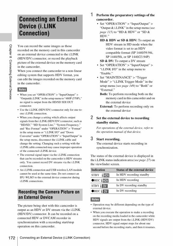
172
Chapter 8 C
onnecting External D
evices
You can record the same images as those recorded on the memory card in this camcorder on an external device connected to the i.LINK (HDV/DV) connector, or record the playback picture of the external device on the memory card in the camcorder.When you connect the camcorder to a non-linear editing system that supports HDV format, you can edit the images recorded on the memory card in the camcorder.
Notes
• When you set “OPERATION” > “Input/Output” > “Output&i.LINK” in the setup menu to “480P (570P),” no signal is output from the HD/SD SDI OUT connector.
• Use the i.LINK (HDV/DV) connector only for one-to-one i.LINK connection.
• When you change a setting which affects output signals from the i.LINK (HDV/DV) connector, such as “HD/SD,” “HD System Line,” “System Frequency,” and “Rec Format” under “OPERATION” > “Format” in the setup menu or “i.LINK I/O” and “Down Converter” under “OPERATION” > “Input/Output” in the setup menu, disconnect the i.LINK cable and change the setting. Changing such a setting with the i.LINK cable connected may cause improper operation of the connected i.LINK device.
• The external signal input via the i.LINK connection that can be recorded on the camcorder is HDV streams only. You cannot record DV streams via the i.LINK connection.
• An i.LINK connection and USB wireless LAN module cannot be used at the same time. Do not connect an IFU-WLM3 to the external device connector during i.LINK connections.
The picture being shot with this camcorder is output as an HDV or DV stream via the i.LINK (HDV/DV) connector. It can be recorded on a connected HDV or DVCAM recorder in synchronization with a recording start/stop operation on this camcorder.
1 Perform the preparatory settings of the camcorder.• Set “OPERATION” > “Input/Output” >
“Output & i.LINK” in the setup menu (see page 115) to “HD & HDV” or “SD & HDV.”HD & HDV or SD & HDV: To output an
HDV stream in HD mode when the video format is set to an HDV compatible format (SP 1440/59.94i, SP 1440/50i, or SP 1440/23.94P)
SD & DV: To output a DV stream• Set “OPERATION” > “Input/Output” >
“i.LINK I/O” in the setup menu to “Enable.”
• Set “MAINTENANCE” > “Trigger Mode” > “i.LINK Trigger Mode” in the setup menu (see page 149) to “Both” or “External.”Both: To perform recording both on the
memory card in this camcorder and on the external device
External: To perform recording only on the external device
2 Set the external device to recording standby status.
For operations of the external device, refer to the operation manual of that device.
3 Start recording.The external device starts recording in synchronization.
The status of the external device is displayed in the i.LINK status indication area (see page 27) on the viewfinder screen.
Notes
• Operation may be different depending on the type of external device.
• When you execute the operation to make a recording on the recording media loaded in the camcorder while HDV signals are output from the i.LINK (HDV/DV) connector, HDV signal output stops for about one second before the recording starts, and then it resumes.
Connecting an External Device (i.LINK Connection)
Recording the Camera Picture on an External Device
Indication Status of the external device
STBY In HDV recording standby
zREC In HDV recording
STBY In DV recording standby
zREC In DV recording
Connecting an External Device (i.LINK Connection)
Chapter 8 C
onnecting External D
evices
• While you can record shot marks on the memory cardduring recording, they are not added to the pictures recorded on the external device.
You can transfer an HDV stream to a nonlinear editing system connected via the i.LINK (HDV/DV) connector.
Notes
• The i.LINK (HDV/DV) connector of this camcorder is a 6-pin connector. Check the number of pins of the i.LINK connector on your computer and use an appropriate i.LINK cable.
• In searching pictures of this camcorder on the computer, it may take some time until the display is reflected on the computer.
• If the playback clip is short or the playback starting point is near the end of the clip, the i.LINK signal may be interrupted between the clip and the next clip. When you try to capture such a signal using the nonlinear editing system, a malfunction may occur, depending on the nonlinear editing software in use.
• If you specify a search speed other than 4, 15, or 24 times normal with the nonlinear editing system, no i.LINK signal is fed out. In such a case, the picture on the viewfinder monitor may stay frozen.
• High-speed playback picture may not be displayed on the computer screen, depending on the nonlinear editing software in use.
Setting on this camcorderSet “OPERATION” > “Input/Output” > “i.LINK I/O” in the setup menu to “Enable.”
For operations of the nonlinear editing software, refer to the operation manual of the software.
The HDV stream input from a device connected via the i.LINK (HDV/DV) connector can be recorded on an SxS memory card in this camcorder.The timecodes superimposed on the i.LINK input are recorded regardless of the settings of the camcorder.
Note
DV stream cannot be recorded.
1 Set the external signal to a format that can be recorded on the camcorder.
Select an HDV compatible format (SP 1440/59.94i, SP 1440/50i, or SP 1440/23.94P) for the video format.
2 Make the following settings with “OPERATION” > “Input/Output” in the setup menu (see page 115).• Set “Output&i.LINK” to “HD&HDV”
or “SD&HDV.”• Set “i.LINK I/O” to “Enable.”• Set “Source Select” to “i.LINK.”The input video is displayed on the viewfinder screen or the monitor connected to the VIDEO OUT connector.Audio signals are output through the built-in speaker, the headphones connected to the EARPHONE connector, and the speakers of the monitor connected to the VIDEO OUT connector.
3 Start the recording.
Notes
• An error is generated in the following cases. In such a case, cancel Recording mode.- The video format of input signal does not match that
specified on the camcorder.- A copy-protected stream is being fed in.
• If the input to the camcorder becomes no signal during recording, the TALLY indicators, the tally indicator on the front of the viewfinder, and the REC indication (zREC) on the viewfinder screen flash, indicating that no signal is being recorded on the SxS memory card.When an input signal is resumed, recording is restarted, incrementing the clip number on the memory card.
Nonlinear Editing
Recording External Input Signals
Connecting an External Device (i.LINK Connection) 173
174
Chapter 8 C
onnecting External D
evices
You can connect USB storage media (such as a HDD or flash memory) to the OPTION connector of the unit to copy clips between SxS memory cards and USB media.
USB media that can be used with this unit must satisfy the following criteria.
Capacity: 3 GB to 2 TBMedia with capacity less than 3 GB is not recognized. Media with capacity exceeding 2 TB is recognized as 2 TB media.
Format: exFATOnly media formatted on the PMW-1000, PMW-50, or this unit can be used. Media formatted using other devices may not operate correctly.
The recommended USB media are as follows.• Sony PSZ-HA1T (1 TB)• Sony PSZ-HA50 (500 GB)• Sony PSZ-SA25 (256 GB)• Sony HD-E1 (1 TB)• Sony HD-EG5 (500 GB)The operation of the following USB media has been verified.• Lacie LCH-RG005T3 (500 GB)• Buffalo HD-PNT2.0U3-GBC (2 TB)
When valid USB media is connected, the USB icon (see page 27) is displayed on the LCD monitor.
Notes
• The correct operation of HDD or USB flash drives that meet the above criteria is not guaranteed.
• This unit is compatible with USB media that operates from a 5.0 V / 0.5 A power source. The unit may not recognize the USB media, depending on the media used. In such cases, supply a separate power source.
• Shooting signals cannot be recorded directly to USB media.
• Do not disconnect USB media while copying or playing back clips on the media.
• Do not connect/disconnect USB media while the camcorder is turned on. It may cause of a malfunction of the camcorder or USB media.
To copy from SxS memory cards to USB mediaCopy clips recorded on SxS memory cards to USB media by selecting “USB Set” >“Copy To USB” in the MAINTENANCE menu when the thumbnail screen is displayed.The copy destination folder is specified using “USB Set” >“Select Folder” in the MAINTENANCE menu. If no folder is selected, a new folder is created and files are copied to it. The name of the new folder uses the recording date of the first clip on the source SxS memory card. If “A&B t USB” is selected, clips on the selected SxS memory card are saved in the folder specified using “Select Folder,” and clips on the unselected SxS memory card are saved in a new folder. You can also copy clips by selecting them on the thumbnail screen. Select the clips and then select “COPY CLIP(A)” or “COPY CLIP(B)” from the Clip Operation menu.
To copy all clips using an assignable buttonAssign the Quick Backup function to an assignable switch, then press the assignable button to copy all clips on the selected SxS memory card to USB media. A new folder is created and files are copied to it.
To copy from USB media to SxS memory cardsCopy clips recorded on USB media to the selected SxS memory card by selecting “USB Set” >“Copy From USB” in the MAINTENANCE menu, when selecting the folder by using “USB Set” > “Select Folder” in the MAINTENANCE menu.
Error checkingYou can turn on error checking when copying clips between USB media and SxS memory cards by setting “USB Set” >“Error Check” to “On” in the MAINTENANCE menu. If an error message appears, try copying the clip again. Copying with error checking enabled takes approximately twice the time as when error checking is disabled.
Connecting USB Media
Supported USB Media
Copying Clips
Connecting USB Media
Chapter 8 C
onnecting External D
evices
Select “USB Set” >“USB Thumbnail” in the MAINTENANCE menu to display the thumbnail screen for clips recorded on USB media. When selecting the folder by using “USB Set” > “Select Folder” in the MAINTENANCE menu, you can also assign the USB Thumbnail function to an assignable button, then press the button to display the USB media thumbnail screen. The operations that can be performed on the USB media thumbnail screen are basically the same as those for the SxS memory card thumbnail screen, although with the following differences. • Functions that are not available
—Adding and deleting shot marks—Adding and deleting OK/NG/KP flags and
OK marks—Setting index pictures—Splitting clips
• Dropped frames and other issues may occur when playing back clips recorded on USB media.
Clip Operation menu
Displaying the USB Media Thumbnail Screen
Item FunctionClip Properties Displays the clip detailed
information screen (see page 100).
Copy Clip (A) Copies the selected clips to the SxS memory card in slot A or slot B (see page 104).
Copy Clip (B)
Copy Clip (USB) Copies the selected clips to a USB media (see page 105).
Delete Clip Deletes the clip (see page 105).
Connecting USB Media 175
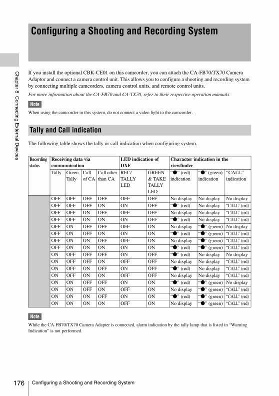
176
Chapter 8 C
onnecting External D
evices
If you install the optional CBK-CE01 on this camcorder, you can attach the CA-FB70/TX70 Camera Adaptor and connect a camera control unit. This allows you to configure a shooting and recording system by connecting multiple camcorders, camera control units, and remote control units.
For more information about the CA-FB70 and CA-TX70, refer to their respective operation manuals.
Note
When using the camcorder in this system, do not connect a video light to the camcorder.
The following table shows the tally or call indication when configuring system.
Note
While the CA-FB70/TX70 Camera Adapter is connected, alarm indication by the tally lamp that is listed in “Warning Indication” is not performed.
Configuring a Shooting and Recording System
Tally and Call indication
Recording status
Receiving data via communication
LED indication of DXF
Character indication in the viewfinder
Tally Green Tally
Call of CA
Call other than CA
REC/TALLY LED
GREEN & TAKETALLY LED
“z” (red) indication
“z” (green) indication
“CALL” indication
OFF OFF OFF OFF OFF OFF No display No display No display
OFF OFF OFF ON ON OFF “z” (red) No display “CALL” (red)
OFF OFF ON OFF OFF OFF No display No display “CALL” (red)
OFF OFF ON ON ON OFF “z” (red) No display “CALL” (red)
OFF ON OFF OFF OFF ON No display “z” (green) No display
OFF ON OFF ON ON ON “z” (red) “z” (green) “CALL” (red)
OFF ON ON OFF OFF ON No display “z” (green) “CALL” (red)
OFF ON ON ON ON ON “z” (red) “z” (green) “CALL” (red)
ON OFF OFF OFF ON OFF “z” (red) No display No display
ON OFF OFF ON OFF OFF No display No display “CALL” (red)
ON OFF ON OFF ON OFF “z” (red) No display “CALL” (red)
ON OFF ON ON OFF OFF No display No display “CALL” (red)
ON ON OFF OFF ON ON “z” (red) “z” (green) No display
ON ON OFF ON OFF ON No display “z” (green) “CALL” (red)
ON ON ON OFF ON ON “z” (red) “z” (green) “CALL” (red)
ON ON ON ON OFF ON No display “z” (green) “CALL” (red)
Configuring a Shooting and Recording System
Chapter 9 M
aintenance
Check the functions of the camcorder before setting out for a shooting session, preferably by recording and playing back video and audio signals. Use a dust blower to clean the lens, the LCD
screen, and mirror inside the viewfinder barrel.
Note
Never use organic solvents such as thinners.
The battery terminal of this unit (the connector for battery packs and AC adaptors) is a consumable part.Power may not be supplied to the unit properly if the pins of the battery terminal are bent or deformed by shock or vibrations, or if they become corroded due to prolonged outdoor use.Periodic inspections are recommended to keep the unit working properly and to prolong its usable lifetime.Contact a Sony service or sales representative for more information about inspections.
Chapter9 Maintenance
Testing the Camcorder Maintenance
Cleaning the Viewfinder
Note about the Battery Terminal
Testing the Camcorder / Maintenance 177
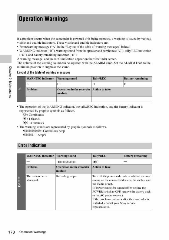
178
Chapter 9 M
aintenance
If a problem occurs when the camcorder is powered or is being operated, a warning is issued by various visible and audible indicators. These visible and audible indicators are:• Error/warning message (“A” in the “Layout of the table of warning messages” below)• WARNING indicator (“B”), warning sound from the speaker and earphones (“C”), tally/REC indication
(“D”), and battery remaining indicator (“E”).A warning message, and the REC indication appear on the viewfinder screen.The volume of the warning sound can be adjusted with the ALARM knob. Set the ALARM knob to the minimum position to suppress the sound.
Layout of the table of warning messages
• The operation of the WARNING indicator, the tally/REC indication, and the battery indicator is represented by graphic symbols as follows.
: Continuous: 1 flash/s: 4 flashes/s
• The warning sounds are represented by graphic symbols as follows.: Continuous beep
: 1 beep/s
Operation WarningsA
WARNING indicator Warning sound Tally/REC Battery remaining
B C D E
Problem Operation in the recorder module
Action to take
Error Indication
E-*
****
WARNING indicator Warning sound Tally/REC Battery remaining
— —
Problem Operation in the recorder module
Action to take
The camcorder is abnormal.
Recording stops. Turn off the power and confirm whether an error occurs on the connected devices, the cables, and the media or not. (If power cannot be turned off by setting the POWER switch to OFF, remove the battery pack or the AC power source.)If the problem continues after the camcorder is restarted, contact your Sony service representative.
Operation Warnings
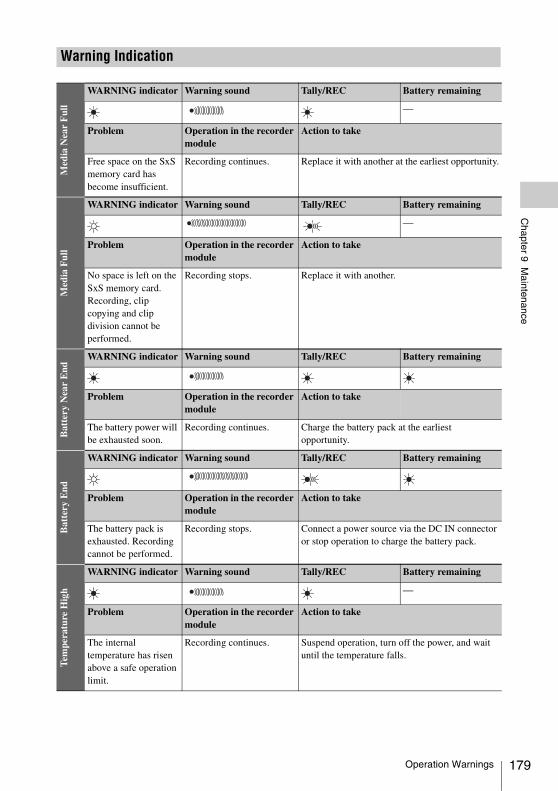
Chapter 9 M
aintenance
Warning IndicationM
edia
Nea
r F
ull
WARNING indicator Warning sound Tally/REC Battery remaining
—
Problem Operation in the recorder module
Action to take
Free space on the SxS memory card has become insufficient.
Recording continues. Replace it with another at the earliest opportunity.
Med
ia F
ull
WARNING indicator Warning sound Tally/REC Battery remaining
—
Problem Operation in the recorder module
Action to take
No space is left on the SxS memory card. Recording, clip copying and clip division cannot be performed.
Recording stops. Replace it with another.
Bat
tery
Nea
r E
nd
WARNING indicator Warning sound Tally/REC Battery remaining
Problem Operation in the recorder module
Action to take
The battery power will be exhausted soon.
Recording continues. Charge the battery pack at the earliest opportunity.
Bat
tery
End
WARNING indicator Warning sound Tally/REC Battery remaining
Problem Operation in the recorder module
Action to take
The battery pack is exhausted. Recording cannot be performed.
Recording stops. Connect a power source via the DC IN connector or stop operation to charge the battery pack.
Tem
pera
ture
Hig
h
WARNING indicator Warning sound Tally/REC Battery remaining
—
Problem Operation in the recorder module
Action to take
The internal temperature has risen above a safe operation limit.
Recording continues. Suspend operation, turn off the power, and wait until the temperature falls.
Operation Warnings 179
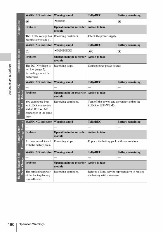
180
Chapter 9 M
aintenance
Vol
tage
Low
WARNING indicator Warning sound Tally/REC Battery remaining
Problem Operation in the recorder module
Action to take
The DC IN voltage has become low (stage 1).
Recording continues. Check the power supply.
Insu
ffic
ient
Vol
tage
WARNING indicator Warning sound Tally/REC Battery remaining
Problem Operation in the recorder module
Action to take
The DC IN voltage is too low (stage 2). Recording cannot be performed.
Recording stops. Connect other power source.
Ple
ase
disc
onne
ct i.
LIN
KN
eed
to R
eboo
t
WARNING indicator Warning sound Tally/REC Battery remaining
— — — —
Problem Operation in the recordermodule
Action to take
You cannot use both an i.LINK connection and an IFU-WLM3 connection at the same time.
Recording continues. Turn off the power, and disconnect either the i.LINK or IFU-WLM3.
Bat
tery
Err
orP
leas
e C
hang
e B
atte
ry. WARNING indicator Warning sound Tally/REC Battery remaining
— — — —
Problem Operation in the recorder module
Action to take
An error was detected with the battery pack.
Recording stops. Replace the battery pack with a normal one.
Bac
kup
Bat
tery
End
Ple
ase
Cha
nge.
WARNING indicator Warning sound Tally/REC Battery remaining
— — — —
Problem Operation in the recorder module
Action to take
The remaining power of the backup battery is insufficient.
Recording continues. Refer to a Sony service representative to replace the battery with a new one.
Operation Warnings
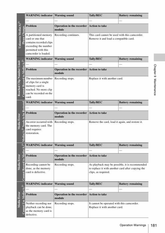
Chapter 9 M
aintenance
Unk
now
n M
edia
(A)1)
Ple
ase
Cha
nge.
WARNING indicator Warning sound Tally/REC Battery remaining
— — — —
Problem Operation in the recorder module
Action to take
A partitioned memory card or one that contains recorded clips exceeding the number permitted with this camcorder is loaded.
Recording continues. This card cannot be used with this camcorder. Remove it and load a compatible card.
Rea
ched
Clip
Num
ber
Lim
it
Can
not
Rec
ord
to M
edia
(A)1)
WARNING indicator Warning sound Tally/REC Battery remaining
— — — —
Problem Operation in the recorder module
Action to take
The maximum number of clips for a single memory card is reached. No more clip can be recorded on the card.
Recording stops. Replace it with another card.
Med
ia E
rror
Med
ia(A
)1) N
eeds
to
be R
esto
red WARNING indicator Warning sound Tally/REC Battery remaining
— — — —
Problem Operation in the recorder module
Action to take
An error occurred with the memory card. The card requires restoration.
Recording stops. Remove the card, load it again, and restore it.
Med
ia E
rror
Can
not
Rec
ord
to M
edia
(A)1) WARNING indicator Warning sound Tally/REC Battery remaining
— — — —
Problem Operation in the recorder module
Action to take
Recording cannot be done, as the memory card is defective.
Recording stops. As playback may be possible, it is recommended to replace it with another card after copying the clips, as required.
Med
ia E
rror
Can
not
Use
Med
ia(A
)1)
WARNING indicator Warning sound Tally/REC Battery remaining
— — — —
Problem Operation in the recorder module
Action to take
Neither recording nor playback can be done, as the memory card is defective.
Recording stops. It cannot be operated with this camcorder. Replace it with another card.
Operation Warnings 181
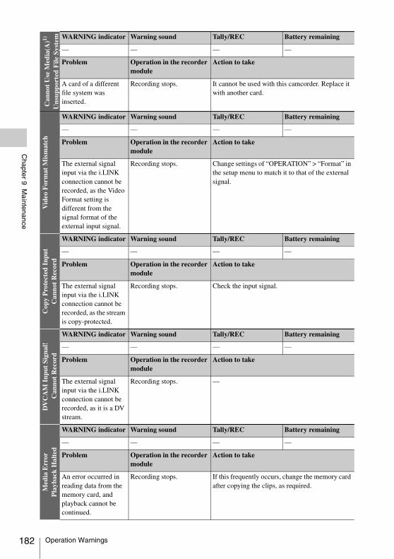
182
Chapter 9 M
aintenance
Can
not
Use
Med
ia(A
)1)
Uns
uppo
rted
File
Sys
tem WARNING indicator Warning sound Tally/REC Battery remaining
— — — —
Problem Operation in the recorder module
Action to take
A card of a different file system was inserted.
Recording stops. It cannot be used with this camcorder. Replace it with another card.
Vid
eo F
orm
at M
ism
atch
WARNING indicator Warning sound Tally/REC Battery remaining
— — — —
Problem Operation in the recorder module
Action to take
The external signal input via the i.LINK connection cannot be recorded, as the Video Format setting is different from the signal format of the external input signal.
Recording stops. Change settings of “OPERATION” > “Format” in the setup menu to match it to that of the external signal.
Cop
y P
rote
cted
Inp
utC
anno
t R
ecor
d
WARNING indicator Warning sound Tally/REC Battery remaining
— — — —
Problem Operation in the recorder module
Action to take
The external signal input via the i.LINK connection cannot be recorded, as the stream is copy-protected.
Recording stops. Check the input signal.
DV
CA
M I
nput
Sig
nal!
Can
not
Rec
ord
WARNING indicator Warning sound Tally/REC Battery remaining
— — — —
Problem Operation in the recorder module
Action to take
The external signal input via the i.LINK connection cannot be recorded, as it is a DV stream.
Recording stops. —
Med
ia E
rror
Pla
ybac
k H
alte
d
WARNING indicator Warning sound Tally/REC Battery remaining
— — — —
Problem Operation in the recorder module
Action to take
An error occurred in reading data from the memory card, and playback cannot be continued.
Recording stops. If this frequently occurs, change the memory card after copying the clips, as required.
Operation Warnings
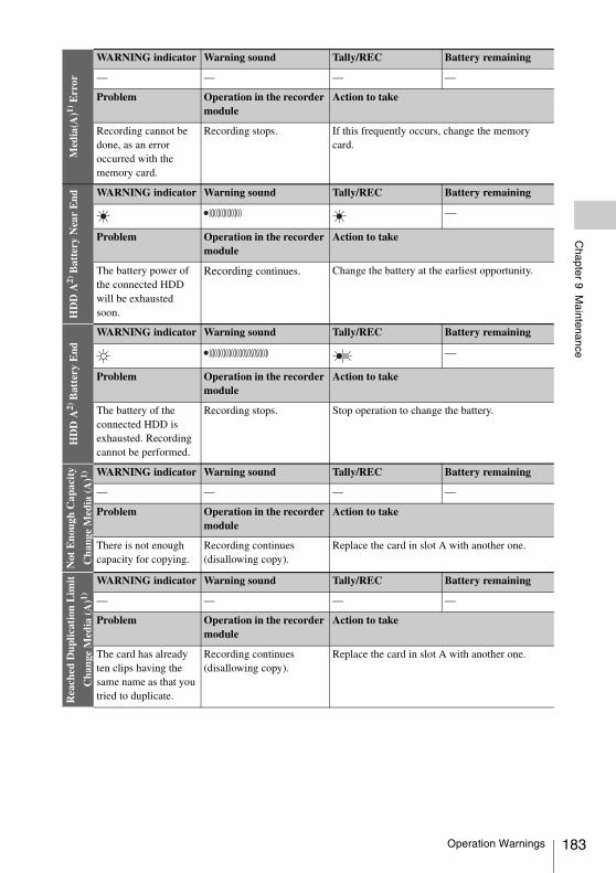
Chapter 9 M
aintenance
Med
ia(A
)1) E
rror
WARNING indicator Warning sound Tally/REC Battery remaining
— — — —
Problem Operation in the recorder module
Action to take
Recording cannot be done, as an error occurred with the memory card.
Recording stops. If this frequently occurs, change the memory card.
HD
D A
2) B
atte
ry N
ear
End WARNING indicator Warning sound Tally/REC Battery remaining
—
Problem Operation in the recorder module
Action to take
The battery power of the connected HDD will be exhausted soon.
Recording continues. Change the battery at the earliest opportunity.
HD
D A
2) B
atte
ry E
nd
WARNING indicator Warning sound Tally/REC Battery remaining
—
Problem Operation in the recorder module
Action to take
The battery of the connected HDD is exhausted. Recording cannot be performed.
Recording stops. Stop operation to change the battery.
Not
Eno
ugh
Cap
acit
y
Cha
nge
Med
ia (
A)1) WARNING indicator Warning sound Tally/REC Battery remaining
— — — —
Problem Operation in the recorder module
Action to take
There is not enough capacity for copying.
Recording continues (disallowing copy).
Replace the card in slot A with another one.
Rea
ched
Dup
licat
ion
Lim
it
Cha
nge
Med
ia (
A)1)
WARNING indicator Warning sound Tally/REC Battery remaining
— — — —
Problem Operation in the recorder module
Action to take
The card has already ten clips having the same name as that you tried to duplicate.
Recording continues (disallowing copy).
Replace the card in slot A with another one.
Operation Warnings 183
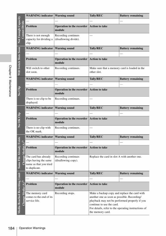
184
Chapter 9 M
aintenance
Not
Eno
ugh
Cap
acit
yC
anno
t D
ivid
e
WARNING indicator Warning sound Tally/REC Battery remaining
— — — —
Problem Operation in the recorder module
Action to take
There is not enough capacity for dividing a clip.
Recording continues (disallowing divide).
—
Will
Sw
itch
Slo
ts S
oon WARNING indicator Warning sound Tally/REC Battery remaining
— — — —
Problem Operation in the recorder module
Action to take
Will switch to other slot soon.
Recording continues. Make sure that a memory card is loaded in the other slot.
No
Clip
WARNING indicator Warning sound Tally/REC Battery remaining
— — — —
Problem Operation in the recorder module
Action to take
There is no clip to be displayed.
Recording continues. —
No
OK
Clip
WARNING indicator Warning sound Tally/REC Battery remaining
— — — —
Problem Operation in the recorder module
Action to take
There is no clip with the OK mark.
Recording continues. —
Sam
e F
ile A
lrea
dy E
xist
s
Cha
nge
Med
ia(A
)1)
WARNING indicator Warning sound Tally/REC Battery remaining
— — — —
Problem Operation in the recorder module
Action to take
The card has already clips having the same name as that you tried to duplicate.
Recording continues (disallowing copy).
Replace the card in slot A with another one.
Med
ia R
each
ed R
ewri
ting
Lim
it
Cha
nge
Med
ia (
A)1)
WARNING indicator Warning sound Tally/REC Battery remaining
— — — —
Problem Operation in the recorder module
Action to take
The memory card comes to the end of its service life.
Recording stops. Make a backup copy and replace the card with another one as soon as possible. Recording/playback may not be performed properly if you continue to use the card.For details, refer to the operating instructions of the memory card.
Operation Warnings
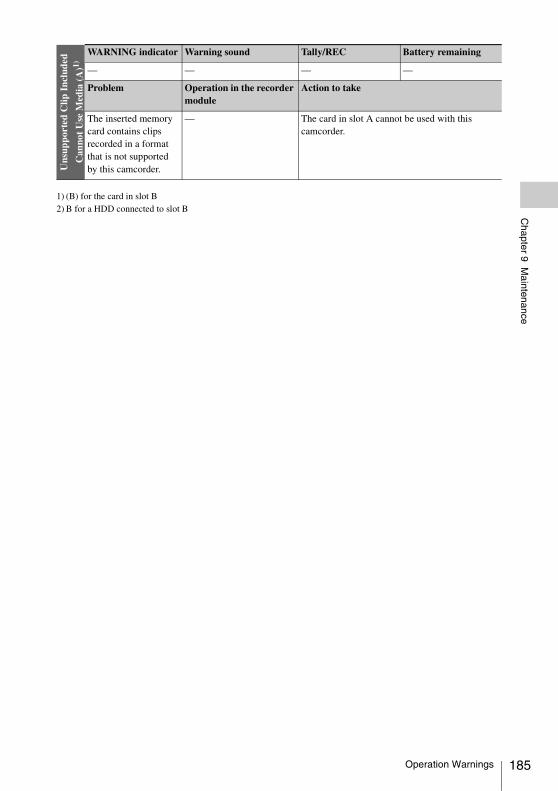
Chapter 9 M
aintenance
1) (B) for the card in slot B2) B for a HDD connected to slot B
Uns
uppo
rted
Clip
Inc
lude
d
Can
not
Use
Med
ia (
A)1)
WARNING indicator Warning sound Tally/REC Battery remaining
— — — —
Problem Operation in the recorder module
Action to take
The inserted memory card contains clips recorded in a format that is not supported by this camcorder.
— The card in slot A cannot be used with this camcorder.
Operation Warnings 185
186
Appendix
Use and storage
Do not subject the camcorder to severe shocks• The internal mechanism may be damaged or the
body warped.• If an accessory mounted on the accessory shoe
is subjected to severe shock, the accessory shoe may be damaged. In such a case, stop using it and contact your dealer or a Sony service representative.
Do not cover the camcorder while operatingPutting a cloth, for example, over the camcorder can cause excessive internal heat build-up.
After useAlways turn off the POWER switch.
Before storing the camcorder for a long periodRemove the battery pack.
Shipping• Remove the media before transporting the
camcorder.• If sending the camcorder by truck, ship, air or
other transportation service, pack it in the shipping carton of the camcorder.
Care of the camcorderRemove dust and dirt from the surfaces of the lenses or optical filters using a blower.If the body of the camcorder is dirty, clean it with a soft, dry cloth. In extreme cases, use a cloth steeped in a little neutral detergent, then wipe dry. Do not use organic solvents such as alcohol or thinners, as these may cause discoloration or other damage to the finish of the camcorder.
In the event of operating problemsIf you should experience problems with the camcorder, contact a Sony service representative.
Use and storage locationsStore in a level, ventilated place. Avoid using or storing the camcorder in the following places.• In excessive heat or cold (operating temperature
range: 0°C to 40°C (32°F to 104°F))• Remember that in summer in warm climates the
temperature inside a car with the windows closed can easily exceed 50°C (122°F).
• In damp or dusty locations• Locations where the camcorder may be exposed
to rain• Locations subject to violent vibration• Near strong magnetic fields• Close to radio or TV transmitters producing
strong electromagnetic fields.• In direct sunlight or close to heaters for
extended periods
To prevent electromagnetic interference from portable communications devicesThe use of portable telephones and other communications devices near this camcorder can result in malfunctions and interference with audio and video signals.It is recommended that the portable communications devices near this camcorder be powered off.
Note on laser beamsLaser beams may damage the CMOS image sensors.If you shoot a scene that includes a laser beam, be careful not to let the laser beam be directed into the lens of the camcorder.
Fitting the zoom lensIt is important to fit the lens correctly, as otherwise damage may result. Be sure to refer to the section “Mounting and Adjusting the Lens” (page 36).
ViewfinderDo not leave the camcorder with the eyepiece pointing directly at the sun.The eyepiece lens can concentrate the sun’s rays and melt the interior of the viewfinder.
Appendix
Important Notes on Operation
Important Notes on Operation
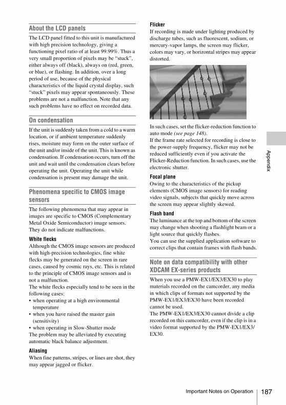
Appendix
About the LCD panelsThe LCD panel fitted to this unit is manufactured with high precision technology, giving a functioning pixel ratio of at least 99.99%. Thus a very small proportion of pixels may be “stuck”, either always off (black), always on (red, green, or blue), or flashing. In addition, over a long period of use, because of the physical characteristics of the liquid crystal display, such “stuck” pixels may appear spontaneously. These problems are not a malfunction. Note that any such problems have no effect on recorded data.
On condensationIf the unit is suddenly taken from a cold to a warm location, or if ambient temperature suddenly rises, moisture may form on the outer surface of the unit and/or inside of the unit. This is known as condensation. If condensation occurs, turn off the unit and wait until the condensation clears before operating the unit. Operating the unit while condensation is present may damage the unit.
Phenomena specific to CMOS image sensorsThe following phenomena that may appear in images are specific to CMOS (Complementary Metal Oxide Semiconductor) image sensors. They do not indicate malfunctions.
White flecksAlthough the CMOS image sensors are produced with high-precision technologies, fine white flecks may be generated on the screen in rare cases, caused by cosmic rays, etc. This is related to the principle of CMOS image sensors and is not a malfunction.The white flecks especially tend to be seen in the following cases:• when operating at a high environmental
temperature• when you have raised the master gain
(sensitivity)• when operating in Slow-Shutter modeThe problem may be alleviated by executing automatic black balance adjustment.
AliasingWhen fine patterns, stripes, or lines are shot, they may appear jagged or flicker.
FlickerIf recording is made under lighting produced by discharge tubes, such as fluorescent, sodium, or mercury-vapor lamps, the screen may flicker, colors may vary, or horizontal stripes may appear distorted.
In such cases, set the flicker-reduction function to auto mode (see page 148).If the frame rate selected for recording is close to the power-supply frequency, flicker may not be reduced sufficiently even if you activate the Flicker-Reduction function. In such cases, use the electronic shutter.
Focal planeOwing to the characteristics of the pickup elements (CMOS image sensors) for reading video signals, subjects that quickly move across the screen may appear slightly skewed.
Flash bandThe luminance at the top and bottom of the screen may change when shooting a flashlight beam or a light source that quickly flashes.You can use the supplied application software to correct clips that contain frames with flash bands.
Note on data compatibility with other XDCAM EX-series productsWhen you use a PMW-EX1/EX3/EX30 to play materials recorded on the camcorder, any media in which clips of formats not supported by the PMW-EX1/EX3/EX30 have been recorded cannot be used.The PMW-EX1/EX3/EX30 cannot divide a clip recorded on this camcorder, even if the clip is in a video format supported by the PMW-EX1/EX3/EX30.
Important Notes on Operation 187
188
Appendix
FragmentationIf pictures cannot be recorded/reproduced properly, try formatting the recording medium.While repeating picture recording/playback with a certain recording medium for an extended period, files in the medium may be fragmented, disabling proper recording/storage. In such a case, make a backup of clips in the medium then perform formatting of the medium using “OPERATION” > “Format Media” (see page 115) in the setup menu.
The camcorder’s internal clock is powered by a lithium battery. If the message “BackUp Battery End” appears in the viewfinder, this battery must be exchanged. Contact a Sony service representative.
Exchanging the Battery of the Internal Clock
Exchanging the Battery of the Internal Clock
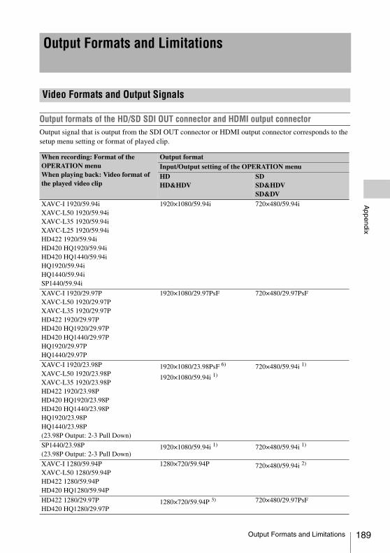
Appendix
Output formats of the HD/SD SDI OUT connector and HDMI output connectorOutput signal that is output from the SDI OUT connector or HDMI output connector corresponds to the setup menu setting or format of played clip.
Output Formats and Limitations
Video Formats and Output Signals
When recording: Format of the OPERATION menuWhen playing back: Video format of the played video clip
Output formatInput/Output setting of the OPERATION menuHDHD&HDV
SDSD&HDVSD&DV
XAVC-I 1920/59.94iXAVC-L50 1920/59.94iXAVC-L35 1920/59.94iXAVC-L25 1920/59.94iHD422 1920/59.94iHD420 HQ1920/59.94iHD420 HQ1440/59.94iHQ1920/59.94iHQ1440/59.94iSP1440/59.94i
1920×1080/59.94i 720×480/59.94i
XAVC-I 1920/29.97PXAVC-L50 1920/29.97PXAVC-L35 1920/29.97PHD422 1920/29.97PHD420 HQ1920/29.97PHD420 HQ1440/29.97PHQ1920/29.97PHQ1440/29.97P
1920×1080/29.97PsF 720×480/29.97PsF
XAVC-I 1920/23.98PXAVC-L50 1920/23.98PXAVC-L35 1920/23.98PHD422 1920/23.98PHD420 HQ1920/23.98PHD420 HQ1440/23.98PHQ1920/23.98PHQ1440/23.98P(23.98P Output: 2-3 Pull Down)
1920×1080/23.98PsF 6)
1920×1080/59.94i 1)
720×480/59.94i 1)
SP1440/23.98P(23.98P Output: 2-3 Pull Down)
1920×1080/59.94i 1) 720×480/59.94i 1)
XAVC-I 1280/59.94PXAVC-L50 1280/59.94PHD422 1280/59.94PHD420 HQ1280/59.94P
1280×720/59.94P 720×480/59.94i 2)
HD422 1280/29.97PHD420 HQ1280/29.97P
1280×720/59.94P 3) 720×480/29.97PsF
Output Formats and Limitations 189
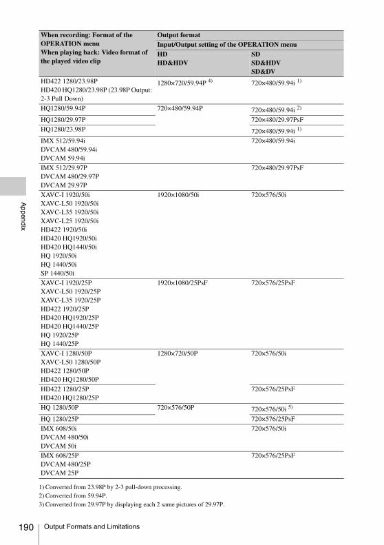
190
Appendix
1) Converted from 23.98P by 2-3 pull-down processing.2) Converted from 59.94P.3) Converted from 29.97P by displaying each 2 same pictures of 29.97P.
HD422 1280/23.98PHD420 HQ1280/23.98P (23.98P Output: 2-3 Pull Down)
1280×720/59.94P 4) 720×480/59.94i 1)
HQ1280/59.94P 720×480/59.94P 720×480/59.94i 2)
HQ1280/29.97P 720×480/29.97PsF
HQ1280/23.98P 720×480/59.94i 1)
IMX 512/59.94iDVCAM 480/59.94iDVCAM 59.94i
720×480/59.94i
IMX 512/29.97PDVCAM 480/29.97PDVCAM 29.97P
720×480/29.97PsF
XAVC-I 1920/50iXAVC-L50 1920/50iXAVC-L35 1920/50iXAVC-L25 1920/50iHD422 1920/50iHD420 HQ1920/50iHD420 HQ1440/50iHQ 1920/50iHQ 1440/50iSP 1440/50i
1920×1080/50i 720×576/50i
XAVC-I 1920/25PXAVC-L50 1920/25PXAVC-L35 1920/25PHD422 1920/25PHD420 HQ1920/25PHD420 HQ1440/25PHQ 1920/25PHQ 1440/25P
1920×1080/25PsF 720×576/25PsF
XAVC-I 1280/50PXAVC-L50 1280/50PHD422 1280/50PHD420 HQ1280/50P
1280×720/50P 720×576/50i
HD422 1280/25PHD420 HQ1280/25P
720×576/25PsF
HQ 1280/50P 720×576/50P 720×576/50i 5)
HQ 1280/25P 720×576/25PsF
IMX 608/50iDVCAM 480/50iDVCAM 50i
720×576/50i
IMX 608/25PDVCAM 480/25PDVCAM 25P
720×576/25PsF
When recording: Format of the OPERATION menuWhen playing back: Video format of the played video clip
Output formatInput/Output setting of the OPERATION menuHDHD&HDV
SDSD&HDVSD&DV
Output Formats and Limitations
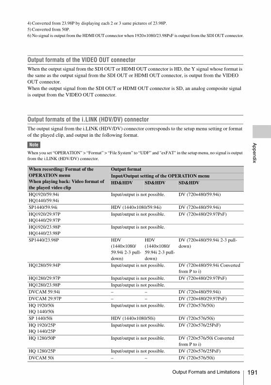
Appendix
4) Converted from 23.98P by displaying each 2 or 3 same pictures of 23.98P.5) Converted from 50P.6) No signal is output from the HDMI OUT connector when 1920×1080/23.98PsF is output from the SDI OUT connector.
Output formats of the VIDEO OUT connector When the output signal from the SDI OUT or HDMI OUT connector is HD, the Y signal whose format is the same as the output signal from the SDI OUT or HDMI OUT connector, is output from the VIDEO OUT connector.When the output signal from the SDI OUT or HDMI OUT connector is SD, an analog composite signal is output from the VIDEO OUT connector.
Output formats of the i.LINK (HDV/DV) connector The output signal from the i.LINK (HDV/DV) connector corresponds to the setup menu setting or format of the played clip, and output in the following format.
Note
When you set “OPERATION” > “Format” > “File System” to “UDF” and "exFAT" in the setup menu, no signal is output from the i.LINK (HDV/DV) connector.
When recording: Format of the OPERATION menuWhen playing back: Video format of the played video clip
Output formatInput/Output setting of the OPERATION menuHD&HDV SD&HDV SD&HDV
HQ1920/59.94iHQ1440/59.94i
Input/output is not possible. DV (720×480/59.94i)
SP1440/59.94i HDV (1440×1080/59.94i) DV (720×480/59.94i)
HQ1920/29.97PHQ1440/29.97P
Input/output is not possible. DV (720×480/29.97PsF)
HQ1920/23.98PHQ1440/23.98P
Input/output is not possible.
SP1440/23.98P HDV (1440×1080/59.94i 2-3 pull-down)
HDV (1440×1080/59.94i 2-3 pull-down)
DV (720×480/59.94i 2-3 pull-down)
HQ1280/59.94P Input/output is not possible. DV (720×480/59.94i Converted from P to i)
HQ1280/29.97P Input/output is not possible. DV (720×480/29.97PsF)
HQ1280/23.98P Input/output is not possible.
DVCAM 59.94i – – DV (720×480/59.94i)
DVCAM 29.97P – – DV (720×480/29.97PsF)
HQ 1920/50iHQ 1440/50i
Input/output is not possible. DV (720×576/50i)
SP 1440/50i HDV (1440×1080/50i) DV (720×576/50i)
HQ 1920/25PHQ 1440/25P
Input/output is not possible. DV (720×576/25PsF)
HQ 1280/50P Input/output is not possible. DV (720×576/50i Converted from P to i)
HQ 1280/25P Input/output is not possible. DV (720×576/25PsF)
DVCAM 50i – – DV (720×576/50i)
Output Formats and Limitations 191
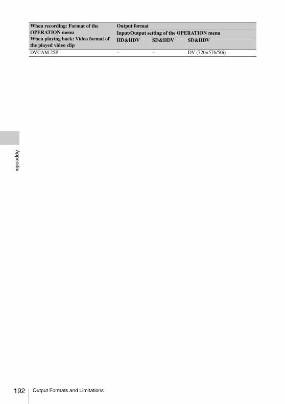
192
Appendix
DVCAM 25P – – DV (720×576/50i)
When recording: Format of the OPERATION menuWhen playing back: Video format of the played video clip
Output formatInput/Output setting of the OPERATION menuHD&HDV SD&HDV SD&HDV
Output Formats and Limitations
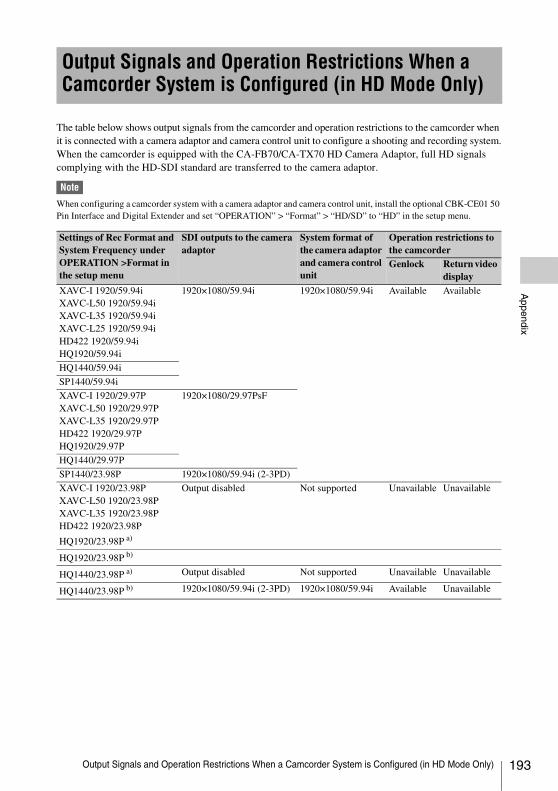
Appendix
The table below shows output signals from the camcorder and operation restrictions to the camcorder when it is connected with a camera adaptor and camera control unit to configure a shooting and recording system.When the camcorder is equipped with the CA-FB70/CA-TX70 HD Camera Adaptor, full HD signals complying with the HD-SDI standard are transferred to the camera adaptor.
Note
When configuring a camcorder system with a camera adaptor and camera control unit, install the optional CBK-CE01 50 Pin Interface and Digital Extender and set “OPERATION” > “Format” > “HD/SD” to “HD” in the setup menu.
Output Signals and Operation Restrictions When a Camcorder System is Configured (in HD Mode Only)
Settings of Rec Format and System Frequency under OPERATION >Format in the setup menu
SDI outputs to the camera adaptor
System format of the camera adaptor and camera control unit
Operation restrictions to the camcorderGenlock Return video
displayXAVC-I 1920/59.94iXAVC-L50 1920/59.94iXAVC-L35 1920/59.94iXAVC-L25 1920/59.94iHD422 1920/59.94iHQ1920/59.94i
1920×1080/59.94i 1920×1080/59.94i Available Available
HQ1440/59.94i
SP1440/59.94i
XAVC-I 1920/29.97PXAVC-L50 1920/29.97PXAVC-L35 1920/29.97PHD422 1920/29.97PHQ1920/29.97P
1920×1080/29.97PsF
HQ1440/29.97P
SP1440/23.98P 1920×1080/59.94i (2-3PD)
XAVC-I 1920/23.98PXAVC-L50 1920/23.98PXAVC-L35 1920/23.98PHD422 1920/23.98P
HQ1920/23.98P a)
Output disabled Not supported Unavailable Unavailable
HQ1920/23.98P b)
HQ1440/23.98P a) Output disabled Not supported Unavailable Unavailable
HQ1440/23.98P b) 1920×1080/59.94i (2-3PD) 1920×1080/59.94i Available Unavailable
Output Signals and Operation Restrictions When a Camcorder System is Configured (in HD Mode Only) 193
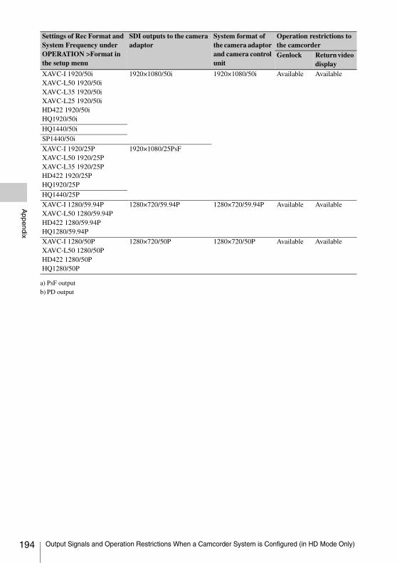
194
Appendix
a) PsF outputb) PD output
XAVC-I 1920/50iXAVC-L50 1920/50iXAVC-L35 1920/50iXAVC-L25 1920/50iHD422 1920/50iHQ1920/50i
1920×1080/50i 1920×1080/50i Available Available
HQ1440/50i
SP1440/50i
XAVC-I 1920/25PXAVC-L50 1920/25PXAVC-L35 1920/25PHD422 1920/25PHQ1920/25P
1920×1080/25PsF
HQ1440/25P
XAVC-I 1280/59.94PXAVC-L50 1280/59.94PHD422 1280/59.94PHQ1280/59.94P
1280×720/59.94P 1280×720/59.94P Available Available
XAVC-I 1280/50PXAVC-L50 1280/50PHD422 1280/50PHQ1280/50P
1280×720/50P 1280×720/50P Available Available
Settings of Rec Format and System Frequency under OPERATION >Format in the setup menu
SDI outputs to the camera adaptor
System format of the camera adaptor and camera control unit
Operation restrictions to the camcorderGenlock Return video
display
Output Signals and Operation Restrictions When a Camcorder System is Configured (in HD Mode Only)
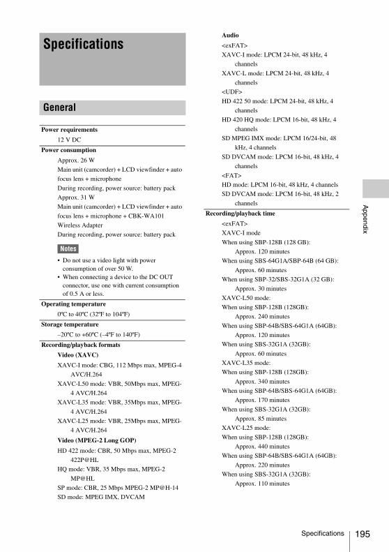
Appendix
Specifications
General
Power requirements
12 V DC
Power consumption
Approx. 26 W
Main unit (camcorder) + LCD viewfinder + auto
focus lens + microphone
During recording, power source: battery pack
Approx. 31 W
Main unit (camcorder) + LCD viewfinder + auto
focus lens + microphone + CBK-WA101
Wireless Adapter
During recording, power source: battery pack
Notes
• Do not use a video light with power consumption of over 50 W.
• When connecting a device to the DC OUT connector, use one with current consumption of 0.5 A or less.
Operating temperature
0ºC to 40ºC (32ºF to 104ºF)
Storage temperature
–20ºC to +60ºC (–4ºF to 140ºF)
Recording/playback formats
Video (XAVC)
XAVC-I mode: CBG, 112 Mbps max, MPEG-4
AVC/H.264
XAVC-L50 mode: VBR, 50Mbps max, MPEG-
4 AVC/H.264
XAVC-L35 mode: VBR, 35Mbps max, MPEG-
4 AVC/H.264
XAVC-L25 mode: VBR, 25Mbps max, MPEG-
4 AVC/H.264
Video (MPEG-2 Long GOP)
HD 422 mode: CBR, 50 Mbps max, MPEG-2
422P@HL
HQ mode: VBR, 35 Mbps max, MPEG-2
MP@HL
SP mode: CBR, 25 Mbps MPEG-2 MP@H-14
SD mode: MPEG IMX, DVCAM
Audio
<exFAT>
XAVC-I mode: LPCM 24-bit, 48 kHz, 4
channels
XAVC-L mode: LPCM 24-bit, 48 kHz, 4
channels
<UDF>
HD 422 50 mode: LPCM 24-bit, 48 kHz, 4
channels
HD 420 HQ mode: LPCM 16-bit, 48 kHz, 4
channels
SD MPEG IMX mode: LPCM 16/24-bit, 48
kHz, 4 channels
SD DVCAM mode: LPCM 16-bit, 48 kHz, 4
channels
<FAT>
HD mode: LPCM 16-bit, 48 kHz, 4 channels
SD DVCAM mode: LPCM 16-bit, 48 kHz, 2
channels
Recording/playback time
<exFAT>
XAVC-I mode
When using SBP-128B (128 GB):
Approx. 120 minutes
When using SBS-64G1A/SBP-64B (64 GB):
Approx. 60 minutes
When using SBP-32/SBS-32G1A (32 GB):
Approx. 30 minutes
XAVC-L50 mode:
When using SBP-128B (128GB):
Approx. 240 minutes
When using SBP-64B/SBS-64G1A (64GB):
Approx. 120 minutes
When using SBS-32G1A (32GB):
Approx. 60 minutes
XAVC-L35 mode:
When using SBP-128B (128GB):
Approx. 340 minutes
When using SBP-64B/SBS-64G1A (64GB):
Approx. 170 minutes
When using SBS-32G1A (32GB):
Approx. 85 minutes
XAVC-L25 mode:
When using SBP-128B (128GB):
Approx. 440 minutes
When using SBP-64B/SBS-64G1A (64GB):
Approx. 220 minutes
When using SBS-32G1A (32GB):
Approx. 110 minutes
Specifications 195
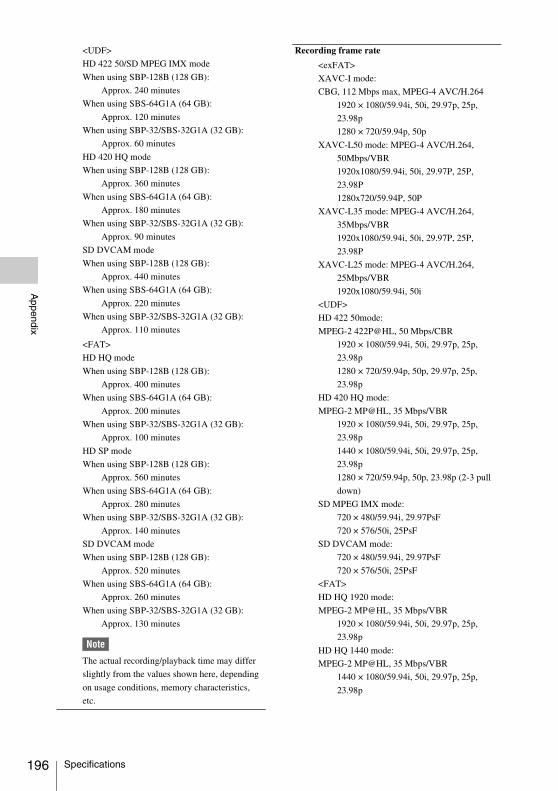
196
Appendix
<UDF>
HD 422 50/SD MPEG IMX mode
When using SBP-128B (128 GB):
Approx. 240 minutes
When using SBS-64G1A (64 GB):
Approx. 120 minutes
When using SBP-32/SBS-32G1A (32 GB):
Approx. 60 minutes
HD 420 HQ mode
When using SBP-128B (128 GB):
Approx. 360 minutes
When using SBS-64G1A (64 GB):
Approx. 180 minutes
When using SBP-32/SBS-32G1A (32 GB):
Approx. 90 minutes
SD DVCAM mode
When using SBP-128B (128 GB):
Approx. 440 minutes
When using SBS-64G1A (64 GB):
Approx. 220 minutes
When using SBP-32/SBS-32G1A (32 GB):
Approx. 110 minutes
<FAT>
HD HQ mode
When using SBP-128B (128 GB):
Approx. 400 minutes
When using SBS-64G1A (64 GB):
Approx. 200 minutes
When using SBP-32/SBS-32G1A (32 GB):
Approx. 100 minutes
HD SP mode
When using SBP-128B (128 GB):
Approx. 560 minutes
When using SBS-64G1A (64 GB):
Approx. 280 minutes
When using SBP-32/SBS-32G1A (32 GB):
Approx. 140 minutes
SD DVCAM mode
When using SBP-128B (128 GB):
Approx. 520 minutes
When using SBS-64G1A (64 GB):
Approx. 260 minutes
When using SBP-32/SBS-32G1A (32 GB):
Approx. 130 minutes
Note
The actual recording/playback time may differ
slightly from the values shown here, depending
on usage conditions, memory characteristics,
etc.
Recording frame rate
<exFAT>
XAVC-I mode:
CBG, 112 Mbps max, MPEG-4 AVC/H.264
1920 × 1080/59.94i, 50i, 29.97p, 25p,
23.98p
1280 × 720/59.94p, 50p
XAVC-L50 mode: MPEG-4 AVC/H.264,
50Mbps/VBR
1920x1080/59.94i, 50i, 29.97P, 25P,
23.98P
1280x720/59.94P, 50P
XAVC-L35 mode: MPEG-4 AVC/H.264,
35Mbps/VBR
1920x1080/59.94i, 50i, 29.97P, 25P,
23.98P
XAVC-L25 mode: MPEG-4 AVC/H.264,
25Mbps/VBR
1920x1080/59.94i, 50i
<UDF>
HD 422 50mode:
MPEG-2 422P@HL, 50 Mbps/CBR
1920 × 1080/59.94i, 50i, 29.97p, 25p,
23.98p
1280 × 720/59.94p, 50p, 29.97p, 25p,
23.98p
HD 420 HQ mode:
MPEG-2 MP@HL, 35 Mbps/VBR
1920 × 1080/59.94i, 50i, 29.97p, 25p,
23.98p
1440 × 1080/59.94i, 50i, 29.97p, 25p,
23.98p
1280 × 720/59.94p, 50p, 23.98p (2-3 pull
down)
SD MPEG IMX mode:
720 × 480/59.94i, 29.97PsF
720 × 576/50i, 25PsF
SD DVCAM mode:
720 × 480/59.94i, 29.97PsF
720 × 576/50i, 25PsF
<FAT>
HD HQ 1920 mode:
MPEG-2 MP@HL, 35 Mbps/VBR
1920 × 1080/59.94i, 50i, 29.97p, 25p,
23.98p
HD HQ 1440 mode:
MPEG-2 MP@HL, 35 Mbps/VBR
1440 × 1080/59.94i, 50i, 29.97p, 25p,
23.98p
Specifications
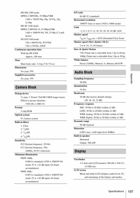
Appendix
HD HQ 1280 mode:
MPEG-2 MP@HL, 35 Mbps/VBR
1280 × 720/59.94p, 50p, 29.97p, 25p,
23.98p
HD SP 1440 mode:
MPEG-2 MP@H-14, 25 Mbps/CBR
1440 × 1080/59.94i, 50i, 23.98p (2-3 pull
down)
SD DVCAM mode:
720 × 480/59.94i, 29.97PsF
720 × 576/50i, 25PsF
Continuous operation time
With the BP-L80S
Approx. 180 min.
Mass
Main body only: 3.4 kg (7 lb 7.9 oz)
Dimensions
See page 200.
Supplied accessories
See page 199.
Camera Block
Pickup device2/3-type, 3-“Exmor” Full HD CMOS image sensors
Effective picture elements:
1920 (H) × 1080 (V)
Format
3-chip RGB
Optical system
F1.4 prism system
Built-in filters
1: Clear
2: 1/4ND
3: 1/16ND
4: 1/64ND
Sensitivity
F12 (System frequency: 59.94i)
F13 (System frequency: 50i)
(2000lx, 89.9% reflection)
Minimum illumination
PMW-400K:
0.006 lx (standard) (1920 × 1080/59.94i
mode, F1.9, +42 dB input, 64-frame
accumulation)
PMW-400L:
0.003 lx (standard) (1920 × 1080/59.94i
mode, F1.4, +42 dB input, 64-frame
accumulation)
S/N ratio
60 dB (Y) (standard)
Horizontal resolution
1000TV lines or more (1920 × 1080i mode)
Gain
–3, 0, 3, 6, 9, 12, 18, 24, 30, 36, 42 dB, AGC
Shutter speed1/60 to 1/2000 sec. + ECS (Extended Clear Scan)
Shutter speed (Slow shutter (SLS))
2 to 8, 16, 32, 64 frames
Slow & Quick Motion
720: Frame rate is selectable from 1 fps to 60 fps
1080p: Frame rate is selectable from 1 fps to 30 fps
White balance
Preset (3200K), Memory A, Memory B/ATW
Audio Block
Sampling frequency
48 kHz
Quantization
16 bits
Headroom
20 dB (the factory default setting)
(20, 18, 16, 12 dB)
Frequency response
MIC: 50 Hz to 20 kHz (within ±3 dB)
LINE: 20 Hz to 20 kHz (within ±3 dB)
WRR Analog: 50 Hz to 20 kHz (within ±3 dB)
WRR Digital: 20 Hz to 20 kHz (within ±3 dB)
Dynamic range
90 dB (typical)
Distortion
0.08% max. (with input level 40dBu)
Built-in speaker
Monaural
Output: 300 mW
Display
Viewfinder
3.5-inch color LCD monitor: 960 (H) × 540 (V),
1/4 HD size
LCD screen
Black and white LCD (displays audio level, TC,
and remaining of the battery and media)
Specifications 197
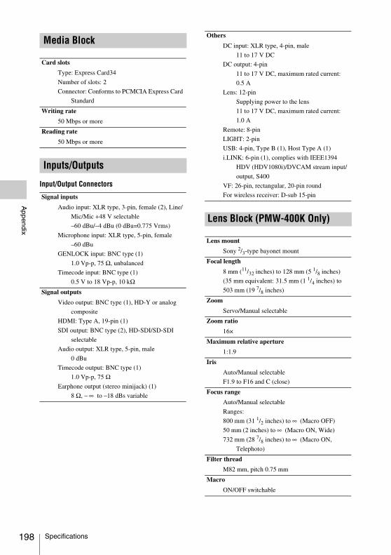
198
Appendix
Input/Output Connectors
Media Block
Card slots
Type: Express Card34
Number of slots: 2
Connector: Conforms to PCMCIA Express Card
Standard
Writing rate
50 Mbps or more
Reading rate
50 Mbps or more
Inputs/Outputs
Signal inputs
Audio input: XLR type, 3-pin, female (2), Line/
Mic/Mic +48 V selectable
–60 dBu/–4 dBu (0 dBu=0.775 Vrms)
Microphone input: XLR type, 5-pin, female
–60 dBu
GENLOCK input: BNC type (1)
1.0 Vp-p, 75 Ω, unbalanced
Timecode input: BNC type (1)
0.5 V to 18 Vp-p, 10 kΩSignal outputs
Video output: BNC type (1), HD-Y or analog
composite
HDMI: Type A, 19-pin (1)
SDI output: BNC type (2), HD-SDI/SD-SDI
selectable
Audio output: XLR type, 5-pin, male
0 dBu
Timecode output: BNC type (1)
1.0 Vp-p, 75 ΩEarphone output (stereo minijack) (1)
8 Ω, – ∞ to –18 dBs variable
Others
DC input: XLR type, 4-pin, male
11 to 17 V DC
DC output: 4-pin
11 to 17 V DC, maximum rated current:
0.5 A
Lens: 12-pin
Supplying power to the lens
11 to 17 V DC, maximum rated current:
1.0 A
Remote: 8-pin
LIGHT: 2-pin
USB: 4-pin, Type B (1), Host Type A (1)
i.LINK: 6-pin (1), complies with IEEE1394
HDV (HDV1080i)/DVCAM stream input/
output, S400
VF: 26-pin, rectangular, 20-pin round
For wireless receiver: D-sub 15-pin
Lens Block (PMW-400K Only)
Lens mount
Sony 2/3-type bayonet mount
Focal length
8 mm (11/32 inches) to 128 mm (5 1/8 inches)
(35 mm equivalent: 31.5 mm (1 1/4 inches) to
503 mm (19 7/8 inches)
Zoom
Servo/Manual selectable
Zoom ratio
16×
Maximum relative aperture
1:1.9
Iris
Auto/Manual selectable
F1.9 to F16 and C (close)
Focus range
Auto/Manual selectable
Ranges:
800 mm (31 1/2 inches) to ∞ (Macro OFF)
50 mm (2 inches) to ∞ (Macro ON, Wide)
732 mm (28 7/8 inches) to ∞ (Macro ON,
Telephoto)
Filter thread
M82 mm, pitch 0.75 mm
Macro
ON/OFF switchable
Specifications
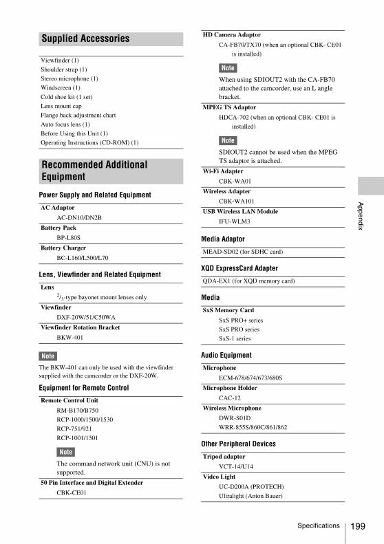
Appendix
Power Supply and Related Equipment
Lens, Viewfinder and Related Equipment
Note
The BKW-401 can only be used with the viewfinder supplied with the camcorder or the DXF-20W.
Equipment for Remote Control
Media Adaptor
XQD ExpressCard Adapter
Media
Audio Equipment
Other Peripheral Devices
Supplied Accessories
Viewfinder (1)
Shoulder strap (1)
Stereo microphone (1)
Windscreen (1)
Cold shoe kit (1 set)
Lens mount cap
Flange back adjustment chart
Auto focus lens (1)
Before Using this Unit (1)
Operating Instructions (CD-ROM) (1)
Recommended Additional Equipment
AC Adaptor
AC-DN10/DN2B
Battery Pack
BP-L80S
Battery Charger
BC-L160/L500/L70
Lens2/3-type bayonet mount lenses only
Viewfinder
DXF-20W/51/C50WA
Viewfinder Rotation Bracket
BKW-401
Remote Control Unit
RM-B170/B750
RCP-1000/1500/1530
RCP-751/921
RCP-1001/1501
Note
The command network unit (CNU) is not supported.
50 Pin Interface and Digital Extender
CBK-CE01
HD Camera Adaptor
CA-FB70/TX70 (when an optional CBK- CE01
is installed)
Note
When using SDIOUT2 with the CA-FB70 attached to the camcorder, use an L angle bracket.
MPEG TS Adaptor
HDCA-702 (when an optional CBK- CE01 is
installed)
Note
SDIOUT2 cannot be used when the MPEG TS adaptor is attached.
Wi-Fi Adapter
CBK-WA01
Wireless Adapter
CBK-WA101
USB Wireless LAN Module
IFU-WLM3
MEAD-SD02 (for SDHC card)
QDA-EX1 (for XQD memory card)
SxS Memory Card
SxS PRO+ series
SxS PRO series
SxS-1 series
Microphone
ECM-678/674/673/680S
Microphone Holder
CAC-12
Wireless Microphone
DWR-S01D
WRR-855S/860C/861/862
Tripod adaptor
VCT-14/U14
Video Light
UC-D200A (PROTECH)
Ultralight (Anton Bauer)
Specifications 199
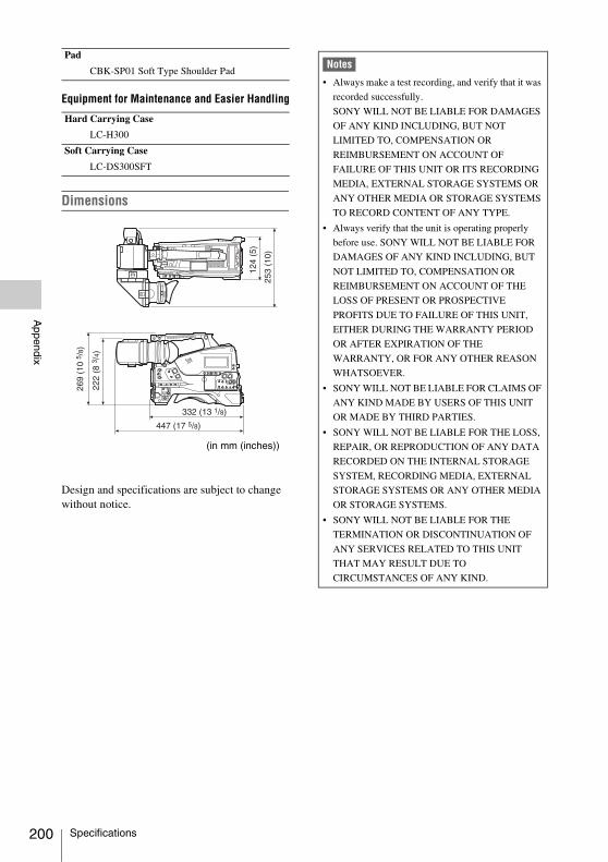
200
Appendix
Equipment for Maintenance and Easier Handling
Dimensions
Design and specifications are subject to change without notice.
Pad
CBK-SP01 Soft Type Shoulder Pad
Hard Carrying Case
LC-H300
Soft Carrying Case
LC-DS300SFT
(in mm (inches))
Notes
• Always make a test recording, and verify that it was
recorded successfully.
SONY WILL NOT BE LIABLE FOR DAMAGES
OF ANY KIND INCLUDING, BUT NOT
LIMITED TO, COMPENSATION OR
REIMBURSEMENT ON ACCOUNT OF
FAILURE OF THIS UNIT OR ITS RECORDING
MEDIA, EXTERNAL STORAGE SYSTEMS OR
ANY OTHER MEDIA OR STORAGE SYSTEMS
TO RECORD CONTENT OF ANY TYPE.
• Always verify that the unit is operating properly
before use. SONY WILL NOT BE LIABLE FOR
DAMAGES OF ANY KIND INCLUDING, BUT
NOT LIMITED TO, COMPENSATION OR
REIMBURSEMENT ON ACCOUNT OF THE
LOSS OF PRESENT OR PROSPECTIVE
PROFITS DUE TO FAILURE OF THIS UNIT,
EITHER DURING THE WARRANTY PERIOD
OR AFTER EXPIRATION OF THE
WARRANTY, OR FOR ANY OTHER REASON
WHATSOEVER.
• SONY WILL NOT BE LIABLE FOR CLAIMS OF
ANY KIND MADE BY USERS OF THIS UNIT
OR MADE BY THIRD PARTIES.
• SONY WILL NOT BE LIABLE FOR THE LOSS,
REPAIR, OR REPRODUCTION OF ANY DATA
RECORDED ON THE INTERNAL STORAGE
SYSTEM, RECORDING MEDIA, EXTERNAL
STORAGE SYSTEMS OR ANY OTHER MEDIA
OR STORAGE SYSTEMS.
• SONY WILL NOT BE LIABLE FOR THE
TERMINATION OR DISCONTINUATION OF
ANY SERVICES RELATED TO THIS UNIT
THAT MAY RESULT DUE TO
CIRCUMSTANCES OF ANY KIND.
Specifications
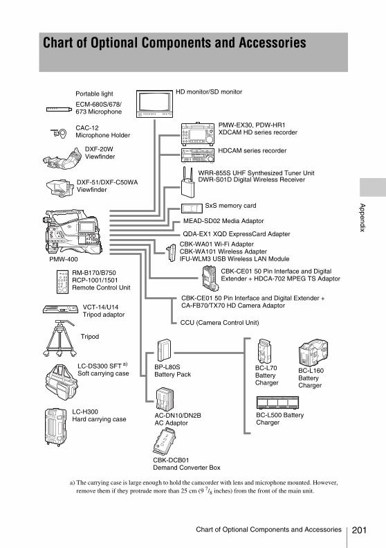
Appendix
Chart of Optional Components and Accessories
a) The carrying case is large enough to hold the camcorder with lens and microphone mounted. However, remove them if they protrude more than 25 cm (9 7/8 inches) from the front of the main unit.
ECM-680S/678/673 Microphone
CAC-12 Microphone Holder
DXF-20W Viewfinder
HD monitor/SD monitor
PMW-EX30, PDW-HR1XDCAM HD series recorder
HDCAM series recorder
WRR-855S UHF Synthesized Tuner UnitDWR-S01D Digital Wireless Receiver
PMW-400
RM-B170/B750RCP-1001/1501Remote Control Unit
VCT-14/U14
Tripod adaptor
Tripod
LC-DS300 SFT a) Soft carrying case
AC-DN10/DN2B AC Adaptor
BC-L500 Battery Charger
BC-L160 Battery Charger
BC-L70 Battery Charger
BP-L80SBattery Pack
SxS memory card
LC-H300 Hard carrying case
DXF-51/DXF-C50WA Viewfinder
MEAD-SD02 Media Adaptor
CBK-WA01 Wi-Fi AdapterCBK-WA101 Wireless AdapterIFU-WLM3 USB Wireless LAN Module
CBK-CE01 50 Pin Interface and Digital Extender + HDCA-702 MPEG TS Adaptor
CBK-CE01 50 Pin Interface and Digital Extender + CA-FB70/TX70 HD Camera Adaptor
CCU (Camera Control Unit)
QDA-EX1 XQD ExpressCard Adapter
Portable light
CBK-DCB01Demand Converter Box
Chart of Optional Components and Accessories 201
202
Appendix
This section explains the specifications and features of i.LINK.
What is i.LINK?i.LINK is a digital serial interface designed to integrate devices equipped with i.LINK connectors. i.LINK allows your device to:• Perform two-way transmission and reception of
data such as digital audio and digital video signals.
• Control other i.LINK devices.• Easily connect multiple devices with a single
i.LINK cable.Your i.LINK device is capable of connecting to a wide range of digital AV devices for data transfer and other operations.Other advantages include the following feature. When connected to multiple i.LINK devices, your i.LINK device can perform data transfer and other operations not onlywith the directly connected devices but also with any of the devices that are connected to those devices. Therefore, you do not need to be concerned with device connection order.However, depending on the features and specifications of the connected devices, you may need to use certain functions differently, and you may not be able to transfer data or perform certain operations.
i.LINK, a nickname for IEEE 1394 proposed by Sony, is a trademark supported by many companies worldwide.IEEE 1394 is an international standard defined by IEEE, the Institute of Electrical and Electronics Engineers, Inc.
Note
The camcorder can be connected to one device with the i.LINK cable (DV cable). When you connect with an HDV or DV device that has two or more i.LINK connectors, refer to the operating instructions supplied with the connected device.
About data transfer speed of i.LINKi.LINK defines a maximum data transfer speed of approximately 100, 200 and 400 Mbps 1) that are described as S100, S200 and S400 respectively.For i.LINK devices, a maximum data transfer speed that the device supports is identified on “Specifications” page of the operating instructions supplied with the device or near its i.LINK connector.1) When connecting with the device that support
different data transfer speed, the actual data transfer speed may be different from those described on the i.LINK connectors.
What is Mbps?Mega bits per second. A measure of the rate at which data is transmitted per second. In case of 100 Mbps, 100 Mega bits of data can be transmitted per second.
i.LINK operation with your camcorderFor details on operation when other equipment with i.LINK (HDV or DV) connector is connected, see page 172.
For details on connection with i.LINK cable and necessary software, refer to the operating instructions supplied with the connected device.
About the required i.LINK cableUse the Sony 6-pin-to-4-pin or 6-pin-to-6-pin i.LINK cable to connect the i.LINK devices.
i.LINK and are trademarks.
About i.LINK
About i.LINK
Appendix
THIS PRODUCT IS LICENSED UNDER THE AVC PATENT PORTFOLIO LICENSE FOR THE PERSONAL USE OF A CONSUMER OR OTHER USES IN WHICH IT DOES NOT RECEIVE REMUNERATION TO
(i) ENCODE VIDEO IN COMPLIANCE WITH THE AVC STANDARD (“AVC VIDEO”) AND/OR(ii) DECODE AVC VIDEO THAT WAS ENCODED BY A CONSUMER ENGAGED IN A PERSONAL ACTIVITY AND/OR WAS OBTAINED FROM A VIDEO PROVIDER LICENSED TO PROVIDE AVC VIDEO.
NO LICENSE IS GRANTED OR SHALL BE IMPLIED FOR ANY OTHER USE. ADDITIONAL INFORMATION MAY BE OBTAINED FROM MPEG LA, L.L.C. SEEHTTP://WWW.MPEGLA.COM
ANY USE OF THIS PRODUCT OTHER THAN CONSUMER PERSONAL USE IN ANY MANNER THAT COMPLIES WITH THE MPEG-2 STANDARD FOR ENCODING VIDEO INFORMATION FOR PACKAGED MEDIA IS EXPRESSLY PROHIBITED WITHOUT A LICENSE UNDER APPLICABLE PATENTS IN THE MPEG-2 PATENT PORTFOLIO, WHICH LICENSE IS AVAILABLE FROM MPEG LA, L.L.C., 250 STEELE STREET, SUITE 300, DENVER, COLORADO 80206.
“PACKAGED MEDIA” means any storage media storing MPEG-2 video information such as DVD movie which are sold/distributed to general
consumers. Disc replicators or sellers of the PACKAGED MEDIA need to obtain licenses for their own business from MPEG LA. Please contact MPEG LA for any further information. MPEG LA. L.L.C., 250 STEELE STREET, SUITE 300, DENVER, COLORADO 80206http://www.mpegla.com
This product uses RICOH Bitmap Fonts produced and sold by Ricoh Company, Ltd.
About License
MPEG-4 AVC Patent Portfolio License
MPEG-2 Video Patent Portfolio License
About Bitmap Fonts
About License / About Bitmap Fonts 203
204
Appendix
Because it uses the OpenSSL Toolkit, this product uses software developed by the OpenSSL Project (http://www.openssl.org/).
OpenSSL License ---------------
/* ==================================================================== * Copyright (c) 1998-2008 The OpenSSL Project. All rights reserved. * * Redistribution and use in source and binary forms, with or without * modification, are permitted provided that the following conditions * are met: * * 1. Redistributions of source code must retain the above copyright * notice, this list of conditions and the following disclaimer. * * 2. Redistributions in binary form must reproduce the above copyright * notice, this list of conditions and the following disclaimer in * the documentation and/or other materials provided with the * distribution. * * 3. All advertising materials mentioning features or use of this * software must display the following acknowledgment: * "This product includes software developed by the OpenSSL Project * for use in the OpenSSL Toolkit. (http://www.openssl.org/)" * * 4. The names "OpenSSL Toolkit" and "OpenSSL Project" must not be used to * endorse or promote products derived from this software without * prior written permission. For written permission, please contact * [email protected]. * * 5. Products derived from this software may not be called "OpenSSL" * nor may "OpenSSL" appear in their names without prior written * permission of the OpenSSL Project. * * 6. Redistributions of any form whatsoever must retain the following * acknowledgment: * "This product includes software developed by the OpenSSL Project * for use in the OpenSSL Toolkit (http://www.openssl.org/)" * * THIS SOFTWARE IS PROVIDED BY THE OpenSSL PROJECT ``AS IS'' AND ANY * EXPRESSED OR IMPLIED WARRANTIES, INCLUDING, BUT NOT LIMITED TO, THE * IMPLIED WARRANTIES OF MERCHANTABILITY AND FITNESS FOR A PARTICULAR * PURPOSE ARE DISCLAIMED. IN NO EVENT SHALL THE OpenSSL PROJECT OR * ITS CONTRIBUTORS BE LIABLE FOR ANY DIRECT, INDIRECT, INCIDENTAL, * SPECIAL, EXEMPLARY, OR CONSEQUENTIAL DAMAGES (INCLUDING, BUT * NOT LIMITED TO, PROCUREMENT OF SUBSTITUTE GOODS OR SERVICES;
About OpenSSL
About OpenSSL
Appendix
* LOSS OF USE, DATA, OR PROFITS; OR BUSINESS INTERRUPTION) * HOWEVER CAUSED AND ON ANY THEORY OF LIABILITY, WHETHER IN CONTRACT, * STRICT LIABILITY, OR TORT (INCLUDING NEGLIGENCE OR OTHERWISE) * ARISING IN ANY WAY OUT OF THE USE OF THIS SOFTWARE, EVEN IF ADVISED * OF THE POSSIBILITY OF SUCH DAMAGE. * ==================================================================== * * This product includes cryptographic software written by Eric Young * ([email protected]). This product includes software written by Tim * Hudson ([email protected]). * */
Original SSLeay License -----------------------
/* Copyright (C) 1995-1998 Eric Young ([email protected]) * All rights reserved. * * This package is an SSL implementation written * by Eric Young ([email protected]). * The implementation was written so as to conform with Netscapes SSL. * * This library is free for commercial and non-commercial use as long as * the following conditions are aheared to. The following conditions * apply to all code found in this distribution, be it the RC4, RSA, * lhash, DES, etc., code; not just the SSL code. The SSL documentation * included with this distribution is covered by the same copyright terms * except that the holder is Tim Hudson ([email protected]). * * Copyright remains Eric Young's, and as such any Copyright notices in * the code are not to be removed. * If this package is used in a product, Eric Young should be given attribution * as the author of the parts of the library used. * This can be in the form of a textual message at program startup or * in documentation (online or textual) provided with the package. * * Redistribution and use in source and binary forms, with or without * modification, are permitted provided that the following conditions * are met: * 1. Redistributions of source code must retain the copyright * notice, this list of conditions and the following disclaimer. * 2. Redistributions in binary form must reproduce the above copyright * notice, this list of conditions and the following disclaimer in the * documentation and/or other materials provided with the distribution. * 3. All advertising materials mentioning features or use of this software * must display the following acknowledgement: * "This product includes cryptographic software written by * Eric Young ([email protected])" * The word 'cryptographic' can be left out if the rouines from the library * being used are not cryptographic related :-). * 4. If you include any Windows specific code (or a derivative thereof) from
About OpenSSL 205
206
Appendix
* the apps directory (application code) you must include an acknowledgement: * "This product includes software written by Tim Hudson ([email protected])" * * THIS SOFTWARE IS PROVIDED BY ERIC YOUNG ``AS IS'' AND * ANY EXPRESS OR IMPLIED WARRANTIES, INCLUDING, BUT NOT LIMITED TO, THE * IMPLIED WARRANTIES OF MERCHANTABILITY AND FITNESS FOR A PARTICULAR PURPOSE * ARE DISCLAIMED. IN NO EVENT SHALL THE AUTHOR OR CONTRIBUTORS BE LIABLE * FOR ANY DIRECT, INDIRECT, INCIDENTAL, SPECIAL, EXEMPLARY, OR CONSEQUENTIAL * DAMAGES (INCLUDING, BUT NOT LIMITED TO, PROCUREMENT OF SUBSTITUTE GOODS * OR SERVICES; LOSS OF USE, DATA, OR PROFITS; OR BUSINESS INTERRUPTION) * HOWEVER CAUSED AND ON ANY THEORY OF LIABILITY, WHETHER IN CONTRACT, STRICT * LIABILITY, OR TORT (INCLUDING NEGLIGENCE OR OTHERWISE) ARISING IN ANY WAY * OUT OF THE USE OF THIS SOFTWARE, EVEN IF ADVISED OF THE POSSIBILITY OF * SUCH DAMAGE. * * The licence and distribution terms for any publically available version or * derivative of this code cannot be changed. i.e. this code cannot simply be * copied and put under another distribution licence * [including the GNU Public Licence.] */
About OpenSSL
Appendix
This product uses the following software, released under MIT License.
jQuery JavaScript Library v1.7.2http://jquery.com/Copyright 2011, John Resig
Sizzle.jshttp://sizzlejs.com/Copyright 2011, The Dojo FoundationDate: Wed Mar 21 12:46:34 2012 -0700
MIT License
Permission is hereby granted, free of charge, to any person obtaining a copy of this software and associated documentation files (the "Software"), to deal in the Software without restriction, including without limitation the rights to use, copy, modify, merge, publish, distribute, sublicense, and/or sell copies of the Software, and to permit persons to whom the Software is furnished to do so, subject to the following conditions:
The above copyright notice and this permission notice shall be included in all copies or substantial portions of the Software.
THE SOFTWARE IS PROVIDED "AS IS", WITHOUT WARRANTY OF ANY KIND, EXPRESS OR IMPLIED, INCLUDING BUT NOT LIMITED TO THE WARRANTIES OF MERCHANTABILITY, FITNESS FOR A PARTICULAR PURPOSE AND NONINFRINGEMENT. IN NO EVENT SHALL THE AUTHORS OR COPYRIGHT HOLDERS BE LIABLE FOR ANY CLAIM, DAMAGES OR OTHER LIABILITY, WHETHER IN AN ACTION OF CONTRACT, TORT OR OTHERWISE, ARISING FROM, OUT OF OR IN CONNECTION WITH THE SOFTWARE OR THE USE OR OTHER DEALINGS IN THE SOFTWARE.
About JQuery,Sizzle.js
About JQuery,Sizzle.js 207
208
Index
A
AC power 29ACCESS lamps 16, 19Accessories (optional) 201Accessory fitting shoe 12Adaptor connector 11ALARM knob 14Area setting 35Arrow buttons (K, k, J, j) 17ASSIGN. 0 switch 14ASSIGN. 1/2/3 switches 14ASSIGNABLE 4/5 switches 19Assignable switches, assigning functions 158ATW (Auto Tracing White Balance) 15Audio control section 17AUDIO IN CH1/CH2 connectors 21AUDIO IN CH-1/CH-2/CH-3/CH-4
switches 18AUDIO IN selectors 21Audio input system 38Audio level
adjusting 55adjusting playback level 14meters 28
AUDIO OUT connector 21AUDIO SELECT CH-1/CH-2 switches 18AUTO W/B BAL switch 13
B
BACKLIGHT button 17Battery
attachment shoe 11of the internal clock, exchanging 188pack 29remaining 26
BKW-401 33Black balance, adjusting 47BRIGHT control 24
C
Camera adaptor 11Clip(s)
batch copy 104copying 104cue up 98defining names 94deleting 86, 105displaying properties 103dividing 107operating with a computer 170operations 96playing 85, 98selecting 97
Clock setting 35Color LCD 16COLOR TEMP. button 14Color temperature 26Connection 168
monitors 168using i.LINK 172using USB 170
CONTRAST control 24Cover 15
D
Date, setting 35DC IN connector 11DC OUT 12V connector 11DCC (Dynamic Contrast Control) 15Depth of field 26Diopter adjustment ring 24DISPLAY switches 17, 24
E
EARPHONE jack 20EJECT buttons 19Electric color temperature filter 27ESSENCE MARK button 18EXPAND button 17Expand thumbnail screen
displaying 105to increase the number of divisions 106
Extender 25External device connector 19External devices 168
control 27
Index
Index
Index
External input 27External power source 26Eyecup 24
F
F FWD button/indicator 16F REV button/indicator 16Filter position 28FILTER selector 13Fitting for optional microphone holder 12Flange focal length, adjusting 23, 36Focus
adjusting 54adjustment mode 27position 25ring 23
FOCUS switch 22Frame Rec 89Framing shots 92Freeze Mix 92F-RUN/SET/R-RUN switch 18
G
GAIN selector 15Gain value 28GENLOCK IN connector 20Green tally 25
H
HD/SD SDI OUT connector 21HDMI output connector 19Histogram 28HOLD button 17
I
i.LINK 202cable 202connection 172
i.LINK (HDV/DV) connector 21Index picture
changing 107Initial value 112Input source 27Internal clock 35Interval Rec 88Iris
position 28ring 23
IRIS switch 23
L
Lenscable clamp 12locking lever 12mount 12mount cap 12mount securing rubber 12mounting 36
LENS connector 12Lens file(s)
loading 167loading automatically 167saving 166setting data 166
LEVEL CH-1/CH-2/CH-3/CH-4 knobs 18LIGHT connector 12LIGHT switch 11
M
MACRO switch 23Maintenance 177Media
remaining capacity 22, 28status 25
MENU button 18MENU CANCEL/PRST/ESCAPE switch 15MENU knob 13MENU ON/OFF switch 15MIC IN (+48 V) connector 12MIC LEVEL control 13Microphone holder 24
fitting 12Microphone, connecting 38MIRROR switch 24MONITOR knob 14MONITOR switches 14Monitor, connecting 168Monochrome LCD Panel 21
N
ND filter 13NEXT button 16Nonlinear editing 171, 173
Index 209
210
Index
Number of system lines 26
O
OK mark(s) 97setting 86
OK/NG/KP mark(s) 103Operation status 25
of i.LINK device 27Optional components 201OUTPUT/DCC switch 15
P
PC connector 19PEAKING control 24Picture Cache 87Planning metadata 93PLAY/PAUSE button/indicator 16Plug 24Power source voltage/battery remaining
capacity 26Power supply 29POWER switch 11Preset values, resetting 165PRESET/REGEN/CLOCK switch 18PREV button 16PUSH AF button 22PUSH AUTO button 23
R
REC START button 13Recording
external input signals 173from pre-stored video 87on an external device 172remaining time 61review 84time-lapse video 88
Recording mode 25, 47special settings indication 26
REMOTE connector 21, 65Remote Control Unit 65Reset 112, 165RESET/RETURN button 17RET button 23RM-B750 65
S
S×S memory card slots 19S×S memory cards 60
ejecting 60formatting 61loading 60restoring 62selecting 61
Scene filesloading 166saving 165
Searchwith the expand thumbnail screen 98with the shot mark thumbnail screen 99
SET button 17Setup menu 109
basic operations 110FILE menu 154MAINTENANCE menu 137menu list 113OPERATION menu 113PAINT menu 131
SHIFT button 18Shooting 60
basic operations 84stop motion animations 89with Slow & Quick motion 90
Shot mark thumbnail screen 106Shot mark(s)
adding 107adding during playback 98defining names 95deleting 107recording 86
Shoulder pad 12adjusting the position 43
Shoulder strap fitting 12Shoulder strap, using 42Shutter
setting 50speed 51
SHUTTER switch 13Slot cover 19SLOT SELECT button 19Speaker 16Specifications 195Status information 59STATUS ON/SEL/OFF switch 15Status screens 59
Index
Index
ASSIGN SWITCH 59AUDIO 59BATTERY/MEDIA 59CAMERA 59VIDEO 59
STOP button 16Stopper 24
T
TALLY indicators 20Tally indicators 24TALLY switch 20, 24TC IN connector 20TC OUT connector 20Testing 177THUMBNAIL button 17THUMBNAIL indicator 17THUMBNAIL menu 100
operations 102Thumbnail screen 96
displaying OK clip thumbnails only 102displaying the all clips thumbnail 102
Thumbnail(s)changing the screen type 102operations 100
Time, setting 35Timecode 27
setting 56synchronizing 57
TLCS automatic adjustment 52TLCS control mode 27Tripod mount 12Tripod, mounting 41
U
UHF portable tuner, attaching 40USB connection 170User bits setting 57User setting data
loading 164saving 163
V
VF connector 12Video format 26, 104
setting 44Video level indication 27
Video light, connecting 42VIDEO OUT connector 20Viewfinder 24
adjusting focus 32adjusting position 30adjusting screen 32adjusting the angle 31attaching 30attaching a 5-inch viewfinder 34cable 24cleaning 177connectors 12fitting shoe 12positioning knob 12positioning lever 12positioning ring 12raising up the barrel and eyepiece 31screen display 25
Voltage capacity 26
W
WARNING indicator 16Warnings 178WHITE BAL switch 15White balance memory 28White balance, adjusting 48Wi-Fi adapter 19Wi-Fi remote commander 82Wireless microphone reception level 26Write protect 22
Z
ZEBRA switch 24Zoom 53
control connector 23position 25power zoom lever 23ring 23
ZOOM switch 23
Index 211