SOLID-STATE MEMORY CAMCORDER PMW-500 - TV Connections
43
SOLID-STATE MEMORY CAMCORDER PMW-500 SUPPLEMENT [English] 1st Edition (Revised 1)
Transcript of SOLID-STATE MEMORY CAMCORDER PMW-500 - TV Connections
SOLID-STATE MEMORY CAMCORDER
PMW-500
SUPPLEMENT [English]1st Edition (Revised 1)

Table of Contents2
Foreword ...................................................................................................... 3
Using an External Hard Disk...................................................................... 3Attaching/Removing the PHU-120R ................................................ 3Formatting the PHU-120R ................................................................ 4Restoring the PHU-120R .................................................................. 5
Using a Media Adaptor ............................................................................... 6
Formatting ......................................................................................... 6
Operating from the RM-B150/B750........................................................... 7Adjusting the Camcorder from the RM-B150/B750......................... 7Operating the Menu from the RM-B150........................................... 9Operating the Menu from the RM-B750........................................... 9
Functions That Can Be Controlled from the RM-B150/B750 ............... 11
Using a Wi-Fi Adapter .............................................................................. 19
Fixing the CBK-WA01 ................................................................... 19Making a Wi-Fi Connection............................................................ 20Using the Web Menu ...................................................................... 21Using Live Logging Functions........................................................ 23
Recording External Input (Pool Feed)..................................................... 23
Editing the USER Menu............................................................................ 31Inserting Items and Sub-Items ........................................................ 31Adding Sub-Items to Existing Items............................................... 32Deleting Items ................................................................................. 33Deleting Sub-Items.......................................................................... 33
Output Formats and Limitations ............................................................. 34
Video Formats and Output Signals (for UDF Mode)...................... 34Video Formats and Output Signals (for FAT Mode) ...................... 35
Table of Contents
This document contains the following supplementary information about the PMW-500 (called “the camcorder” below).• Using a External Hard Disk• Using a Media Adaptor• Operating from the RM-B150/B750• Functions That Can Be Controlled from the
RM-B150/B750• Using a Wi-Fi Adapter• Recording External Input (Pool Feed)• Editing the USER Menu• Output Formats and Limitations
When FAT mode is selected, you can use an optional PHU-120R Professional Hard Disk Unit with this camcorder.
Notes
• In UDF mode, the PHU-120R cannot be used.• High-speed playback may not be possible with the
PHU-120R.• When using the Slow & Quick Motion function with
the PHU-120R, you cannot perform slow motion shooting.
Recording/playback can be made using the PHU-120R in the same manner as with SxS memory cards if you connect the PHU connection cable of the PHU-120R to an SxS memory card slot of the camcorder.
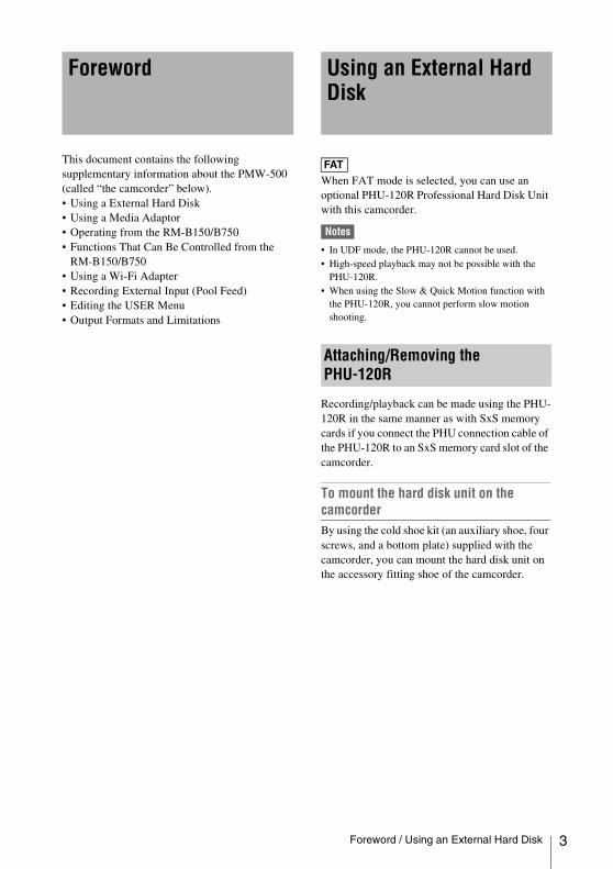
To mount the hard disk unit on the camcorderBy using the cold shoe kit (an auxiliary shoe, four screws, and a bottom plate) supplied with the camcorder, you can mount the hard disk unit on the accessory fitting shoe of the camcorder.
Foreword Using an External Hard Disk
FAT
Attaching/Removing the PHU-120R
Foreword / Using an External Hard Disk 3
4
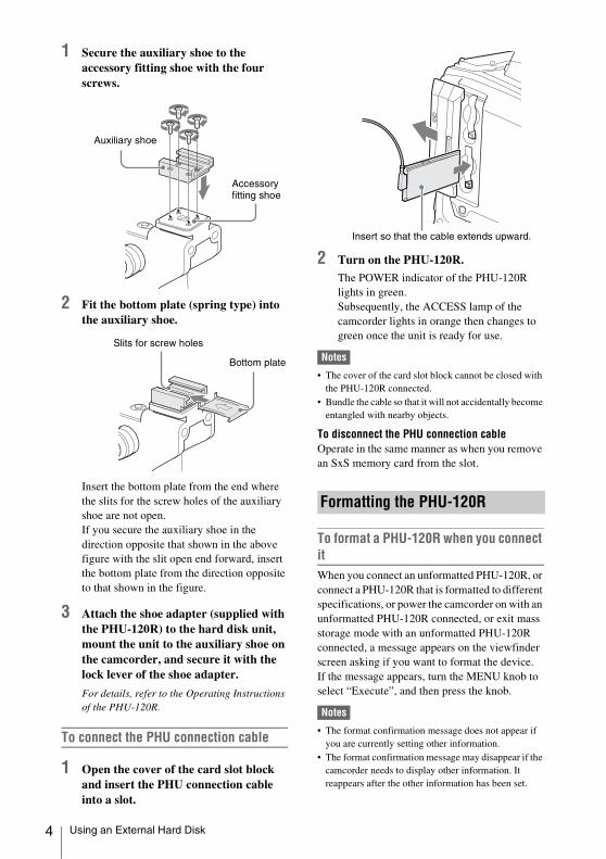
1 Secure the auxiliary shoe to the accessory fitting shoe with the four screws.
2 Fit the bottom plate (spring type) into the auxiliary shoe.
Insert the bottom plate from the end where the slits for the screw holes of the auxiliary shoe are not open.If you secure the auxiliary shoe in the direction opposite that shown in the above figure with the slit open end forward, insert the bottom plate from the direction opposite to that shown in the figure.
3 Attach the shoe adapter (supplied with the PHU-120R) to the hard disk unit, mount the unit to the auxiliary shoe on the camcorder, and secure it with the lock lever of the shoe adapter.
For details, refer to the Operating Instructions of the PHU-120R.
To connect the PHU connection cable
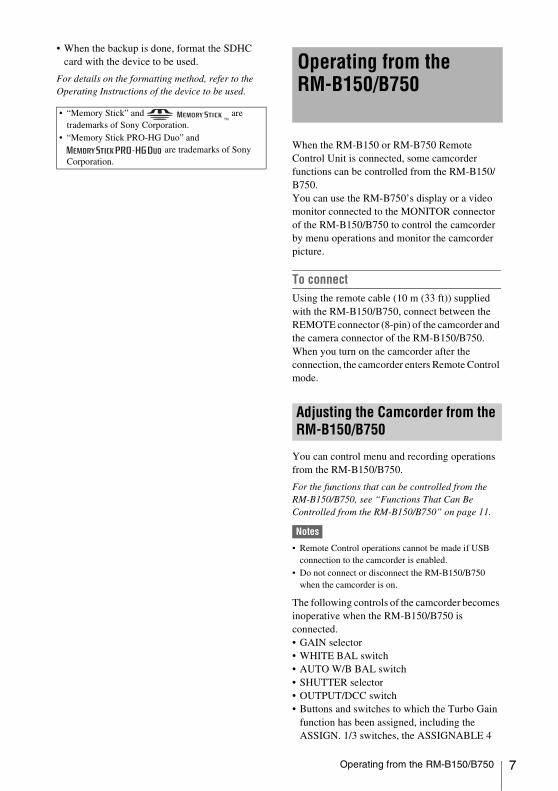
1 Open the cover of the card slot block and insert the PHU connection cable into a slot.
2 Turn on the PHU-120R.
The POWER indicator of the PHU-120R lights in green.Subsequently, the ACCESS lamp of the camcorder lights in orange then changes to green once the unit is ready for use.
Notes
• The cover of the card slot block cannot be closed with the PHU-120R connected.
• Bundle the cable so that it will not accidentally become entangled with nearby objects.
To disconnect the PHU connection cableOperate in the same manner as when you remove an SxS memory card from the slot.
To format a PHU-120R when you connect itWhen you connect an unformatted PHU-120R, or connect a PHU-120R that is formatted to different specifications, or power the camcorder on with an unformatted PHU-120R connected, or exit mass storage mode with an unformatted PHU-120R connected, a message appears on the viewfinder screen asking if you want to format the device.If the message appears, turn the MENU knob to select “Execute”, and then press the knob.
Notes
• The format confirmation message does not appear if you are currently setting other information.
• The format confirmation message may disappear if the camcorder needs to display other information. It reappears after the other information has been set.
Auxiliary shoe
Accessory fitting shoe
Bottom plate
Slits for screw holes
Formatting the PHU-120R
Insert so that the cable extends upward.
Using an External Hard Disk

To format a PHU-120R from a menuYou can format a PHU-120R by using OPERATION >Format Media in the setup menu. This command is available when the PHU-120R is already formatted, unformatted, and formatted in an unsupported format.
1 Select OPERATION >Format Media in the setup menu.
2 Select [Media(A)] (slot A) or [Media(B)] (slot B).
3 Turn the MENU knob to select [Execute], and press the knob.The format confirmation message appears on the viewfinder screen.
4 Turn the MENU knob to select “Execute”, and then press the knob.
For information about menu operations, refer to the operation manual of the camcorder.
Formatting begins.During restoration, an in-progress message and status bar (%) are displayed, and the ACCESS lamp lights in orange.When formatting is completed, a completion message is displayed for three seconds.
If an error occurs with data on the PHU-120R for some reason, the hard disk must be restored.If a PHU-120R that needs to be restored is connected, a message that prompts you to execute restoration is displayed on the viewfinder screen.
To restore the hard diskTurn the MENU knob to select “Execute”, and then press the knob. The restoration begins automatically.During restoration, an in-progress message and status bar (%) are displayed, and the ACCESS lamp lights in orange.When restoration is completed, a completion message is displayed for three seconds.
If restoration fails• A PHU-120R on which an error occurred may
become usable again through repeated formatting.
• In some cases, some clips cannot be restored. Playback of clips that can be restored becomes possible again.
Restoring the PHU-120R
Using an External Hard Disk 5

6
When FAT mode is selected, use of the optional MEAD-MS01 or MEAD-SD01 Media Adaptor permits you to insert a “Memory Stick” (with MEAD-MS01) or an SDHC card (with MEAD-SD01) to the SxS memory card slot of the camcorder and use it for recording and playback in the same way as with an SxS memory card.
Usable “Memory Stick”“Memory Stick PRO-HG Duo” HXA series
Usable SDHC cardClass 10 SDHC card
For details on use of the MEAD-MS01/SD01 Media Adaptor, refer to the Operating Instructions of the adaptor.
Notes
• In UDF mode, no Media Adaptor can be used.• High-speed playback may not be properly achieved
with a “Memory Stick” or an SDHC card.• When using the Slow & Quick Motion function with
the “Memory Stick” or an SDHC card, you cannot perform slow motion shooting.
When you use a “Memory Stick” or an SDHC card with this camcorder, formatting is required.A “Memory Stick” or an SDHC card to be used with this camcorder must be formatted using the format function of this camcorder.It is also necessary to format a “Memory Stick” or an SDHC card for use if a caution message is displayed when you mount the “Memory Stick” or SDHC card.For a “Memory Stick” or an SDHC card that was formatted with another system unsupported by this camcorder, the message “Unsupported File System” is displayed on the LCD monitor/EVF screen.Format the “Memory Stick” or SDHC card as instructed below.
To execute formatting
1 Select OPERATION >Format Media in the setup menu.
2 Select [Media(A)] (slot A) or [Media(B)] (slot B).
3 Turn the MENU knob to select [Execute], and press the knob.The format confirmation message appears on the viewfinder screen.
4 Turn the MENU knob to select “Execute”, and then press the knob.
For information about menu operations, refer to the operation manual of the camcorder.
Formatting begins.An in-progress message and status bar (%) are displayed, and the ACCESS lamp lights in orange. When formatting is completed, a completion message is displayed for three seconds.
Note
In formatting, all data in a “Memory Stick” or MEAD-SD01, including protected images, are erased and cannot be restored.
Connection between the camcorder and a computerTo use a “Memory Stick” or MEAD-SD01 in which data have been recorded with an XDCAM EX-series product, establish USB connection between the computer and this camcorder and insert it into the slot of the camcorder, or use a specified USB card reader SBAC-US10.
To use a “Memory Stick” formatted with this camcorder with other devices having a “Memory Stick” slot• First make a backup copy of the data recorded
in the “Memory Stick.”• When the backup is done, format the “Memory
Stick” with the device to be used.
For details on the formatting method, refer to the Operating Instructions of the device to be used.
To use an SDHC card formatted with this camcorder with other devices having an SDHC card slot• First make a backup copy of the data recorded
in the SDHC card.
Using a Media Adaptor
FAT
Formatting
Using a Media Adaptor
• When the backup is done, format the SDHC card with the device to be used.
For details on the formatting method, refer to the Operating Instructions of the device to be used.
When the RM-B150 or RM-B750 Remote Control Unit is connected, some camcorder functions can be controlled from the RM-B150/B750.You can use the RM-B750’s display or a video monitor connected to the MONITOR connector of the RM-B150/B750 to control the camcorder by menu operations and monitor the camcorder picture.
To connectUsing the remote cable (10 m (33 ft)) supplied with the RM-B150/B750, connect between the REMOTE connector (8-pin) of the camcorder and the camera connector of the RM-B150/B750.When you turn on the camcorder after the connection, the camcorder enters Remote Control mode.
You can control menu and recording operations from the RM-B150/B750.
For the functions that can be controlled from the RM-B150/B750, see “Functions That Can Be Controlled from the RM-B150/B750” on page 11.
Notes
• Remote Control operations cannot be made if USB connection to the camcorder is enabled.
• Do not connect or disconnect the RM-B150/B750 when the camcorder is on.
The following controls of the camcorder becomes inoperative when the RM-B150/B750 is connected.• GAIN selector• WHITE BAL switch• AUTO W/B BAL switch• SHUTTER selector• OUTPUT/DCC switch• Buttons and switches to which the Turbo Gain
function has been assigned, including the ASSIGN. 1/3 switches, the ASSIGNABLE 4
• “Memory Stick” and are trademarks of Sony Corporation.
• “Memory Stick PRO-HG Duo” and are trademarks of Sony
Corporation.
Operating from the RM-B150/B750
Adjusting the Camcorder from the RM-B150/B750
Operating from the RM-B150/B750 7
8
switch, the COLOR TEMP. button, and the ASSIGNABLE 5 switch.
• REC START button: the VTR button on the lens, and buttons and switches to which the function has been assigned using OPERATION >Assignable SW in the setup menu, including the ASSIGN. 1/3 switches, the ASSIGNABLE 4 switch, the COLOR TEMP. button, and the ASSIGNABLE 5 switch (when MAINTENANCE >Camera Config >RM Rec Start in the setup menu is set to [RM]).
To connect the monitor to the RM-B150/B750The MONITOR connector (BNC type) of the RM-B150/B750 outputs a composite signal. To connect a monitor to the MONITOR connector on the RM-B150/B750, use the black cable supplied with the RM-B150/B750.
To release Remote Control modeTurn off the camcorder and disconnect the RM-B150/B750.The settings on the controls on the camcorder become valid.
Camera image quality adjustment items when the RM-B150/B750 is connectedWhen the RM-B150/B750 is connected, the parameters for camera image quality adjustment items (paint data) are reset to the parameters that were specified the last time that RM-B150/B750 was connected.
Function of the recording start/stop buttons when the RM-B150/B750 is connectedWhen the RM-B150/B750 is connected, you can make a setting to determine which of the recording start/stop buttons you will use. This setting is made using MAINTENANCE >Camera Config >RM Rec Start in the setup menu.
Relationship between the setting of the RM Rec Start item and the function of recording start/stop buttons
Structure of the paint adjustment dataThe non-volatile memory of the camcorder used for storing paint adjustment data consists of two regions as shown below: one is the “main data block” that is used when a remote control unit is not connected, and the other is the “remote control data block” that is used when a remote control unit is connected. Paint adjustment data is automatically selected and output to the camera section depending on whether or not a remote control unit such as the RM-B150 is connected.
Recording start/stop button
Settings of RM Rec StartRM CAM PARA
Camcorder’s REC START button
Disabled Enabled Enabled
Lens’ VTR button Disabled Enabled Enabled
Buttons and switches to which the recording start/stop function has been assigned (ASSIGN. 1/3 switches, ASSIGNABLE 4 switch, COLOR TEMP. button, and ASSIGNABLE 5 switch)
Disabled Enabled Enabled
Remote control unit’s VTR button
Enabled Disabled Enabled
Operating from the RM-B150/B750

When a remote control unit is connected to the camcorder, the “remote control data block” is selected as the current paint data block, and the paint adjustment parameters that were in effect the last time the remote control unit was used are recalled.The settings of the absolute value rotational controls 1) and absolute value switches 2) are overwritten by those on the remote control unit after the remote control unit is connected.When the remote control unit is disconnected from the camcorder, the “main data block” becomes effective. Thus the camcorder will return to the settings that were in effect before the remote control unit was connected.1) Absolute value rotational controls: The data
corresponding to the angular position of controls is output. Rotational controls for which the data corresponding to the amount of their rotation is output are called relative value controls.
2) Absolute value switches: Like toggle switches or slide switches (except most momentary switches), the switches (or knobs) whose positions must coincide with their functions are called absolute value switches.
When MAINTENANCE >Camera Config >RM Common Memory is set to [On] in the setup menu, you can use settings of the paint adjustment data stored in the main data block even if you connect the remote control unit. In this case, the settings stored in the main data block will be renewed when you change the
settings on the remote control unit. Thus, the settings of the paint data made with the remote control unit can be retained even if the remote control unit is removed. However, if the switch position on the remote control unit differs from the one on the camcorder, the switch position on the camcorder takes precedence over that on the remote control unit.Also, it is possible to keep the settings that are in effect before you connect the remote control unit. In this case, you should set the control knob to the relative value mode on the remote control unit.
For details, refer to the operation manual supplied with the remote control unit.
1 Set the DISPLAY switch to MENU.
The camcorder menus can be displayed on a video monitor connected to the MONITOR connector of the RM-B150.
2 Select and set the menu items, using the MENU SELECT knob and the CANCEL/ENTER switch.
3 When the settings are completed, set the DISPLAY switch to ON or OFF to exit the menu.
For details on operations of the RM-B150, refer to the operation manual of the RM-B150.
1 Press and light the MONITOR button then press the VF MENU button.
The camcorder menus can be displayed on the RM-B750’s display or a video monitor connected to the MONITOR connector of the RM-B750.
2 Select and set the menu items, using the MENU SELECT knob, ENTER button, and CANCEL button.
3 When the settings are completed, press the VF MENU button to exit the menu.
RM-B150
MASTER BLACKMASTER GAMMAKNEE POINTDETAIL LEVELR/B GAINR/B BLACK
MASTER BLACKMASTER GAMMAKNEE POINTDETAIL LEVELR/B GAINR/B BLACK
Hardware of the camera section
RM-B150 connected
RM-B150 not connected
Main data block Remote control data block
Setup menu of the camcorder
Non-volatile memory
Operating the Menu from the RM-B150
Operating the Menu from the RM-B750
Operating from the RM-B150/B750 9
10
For details on operations of the RM-B750, refer to the operation manual of the RM-B750.
Operating from the RM-B150/B750
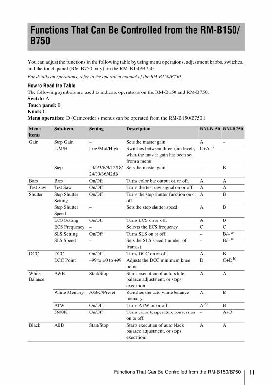
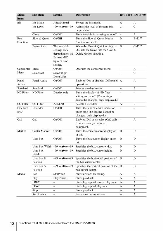
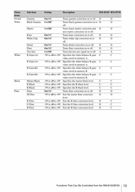
You can adjust the functions in the following table by using menu operations, adjustment knobs, switches, and the touch panel (RM-B750 only) on the RM-B150/B750.
For details on operations, refer to the operation manual of the RM-B150/B750.
How to Read the TableThe following symbols are used to indicate operations on the RM-B150 and RM-B750.Switch: ATouch panel: BKnob: CMenu operation: D (Camcorder’s menus can be operated from the RM-B150/B750.)
Functions That Can Be Controlled from the RM-B150/B750
Menu items
Sub-item Setting Description RM-B150 RM-B750
Gain Step Gain – Sets the master gain. A –
L/M/H Low/Mid/High Switches between three gain levels, when the master gain has been set from a menu.
C+A a) –
Step –3/0/3/6/9/12/18/24/30/36/42dB
Sets the master gain. – B
Bars Bars On/Off Turns color bar output on or off. A A
Test Saw Test Saw On/Off Turns the test saw signal on or off. A A
Shutter Step Shutter Setting
On/Off Turns the step shutter function on or off.
A B
Step Shutter Speed
– Sets the step shutter speed. A B
ECS Setting On/Off Turns ECS on or off. A B
ECS Frequency – Selects the ECS frequency. C C
SLS Setting On/Off Turns SLS on or off. – B/– a)
SLS Speed – Sets the SLS speed (number of frames).
– B/– a)
DCC DCC On/Off Turns DCC on or off. A B
DCC Point –99 to ±0 to +99 Adjusts the DCC minimum knee point.
D C+D b)
White Balance
AWB Start/Stop Starts execution of auto white balance adjustment, or stops execution.
A A
White Memory A/B/C/Preset Switches the auto white balance memory.
A B
ATW On/Off Turns ATW on or off. A c) B
5600K On/Off Turns color temperature conversion on or off.
– A+B
Black ABB Start/Stop Starts execution of auto black balance adjustment, or stops execution.
A A
Functions That Can Be Controlled from the RM-B150/B750 11
12
Iris Iris Mode Auto/Manual Selects the iris mode. A A
Iris Level –99 to ±0 to +99 Adjusts the level of the auto iris target value.
C C
Close On/Off Turns forcible iris closing on or off. – A
Rec Function
Slow & Quick On/Off Turns the Slow & Quick Motion function on or off.
D B+D b)
Frame Rate The available settings vary depending on the Format >HD System Line setting.
When the Slow & Quick setting is On, sets the frame rate for Slow & Quick Motion shooting.
D C+D b)
Camcorder Menu
Menu On/Off Operates the camcorder menu. – A
Select/Set Select (Up/Down)/Set
– C
Panel Active
Panel Active On/Off Enables (On) or disables (Off) panel operations.
A A
Standard Standard On/Off Selects standard mode. A A
ND Filter ND Filter Display only Turns the display of ND filter settings on or off. (The settings cannot be changed, only displayed.)
– –
CC Filter CC Filter A/B/C/D Selects a CC filter. A B
Extender IND
Extender On/Off Turns the lens extender indication on or off. (The settings cannot be changed, only displayed.)
– –
Call Call On/Off Enables (On) or disables (Off) calls from externally connected equipment.
– A
Marker Center Marker On/Off Turns the center marker display on or off.
D D
User Box On/Off Turns the box cursor display on or off.
D D
User Box Width –99 to ±0 to +99 Specifies the box cursor width. D D
User Box Height
–99 to ±0 to +99 Specifies the box cursor height. D D
User Box H Position
–99 to ±0 to +99 Specifies the horizontal position of the box cursor center.
D D
User Box V Position
–99 to ±0 to +99 Specifies the vertical position of the box cursor center.
D D
Media Rec Start/Stop Starts or stops recording. A A
Play Play/Pause Starts playback. A A
FREV – Starts high-speed reverse playback. A A
FFWD – Starts high-speed playback A A
Stop – Stops playback. A A
Rec Review – Starts a recording review. A A
Menu items
Sub-item Setting Description RM-B150 RM-B750
Functions That Can Be Controlled from the RM-B150/B750
Switch Status
Gamma On/Off Turns gamma correction on or off. D D
Black Gamma On/Off Turns black gamma correction on or off.
D D
Matrix On/Off Turns linear matrix correction and user matrix correction on or off.
D D
Knee On/Off Turns knee correction on or off. D D
White Clip On/Off Turns white clip correction on or off.
D D
Detail On/Off Turns detail correction on or off. D D
Flare On/Off Turns flare correction on or off. D D
Test Saw On/Off Turns the test saw signal on or off. A A
White R Gain<A> –99 to ±0 to +99 Specifies the white balance R gain value saved in memory A.
C C
B Gain<A> –99 to ±0 to +99 Specifies the white balance B gain value saved in memory A.
C C
R Gain<B> –99 to ±0 to +99 Specifies the white balance R gain value saved in memory B.
C C
B Gain<B> –99 to ±0 to +99 Specifies the white balance B gain value saved in memory B.
C C
Black Master Black –99 to ±0 to +99 Specifies the master black level. C C
R Black –99 to ±0 to +99 Specifies the R black level. C C
B Black –99 to ±0 to +99 Specifies the B black level. C C
Flare Flare On/Off Turns flare correction on or off. D D
M Flare –99 to ±0 to +99 Sets the master flare correction level.
D D
R Flare –99 to ±0 to +99 Sets the R flare correction level. D C
G Flare –99 to ±0 to +99 Sets the G flare correction level. D C
B Flare –99 to ±0 to +99 Sets the B flare correction level. D C
Menu items
Sub-item Setting Description RM-B150 RM-B750
Functions That Can Be Controlled from the RM-B150/B750 13

14
Gamma Gamma On/Off Turns gamma correction on or off. D B
Step Gamma 0.35 to 0.45 to 0.90 (in steps of 0.05)
Specifies a gamma correction value in steps of 0.05.
D D
Master Gamma –99 to ±0 to +99 Specifies the master gamma level. C C
R Gamma –99 to ±0 to +99 Specifies the R gamma level. D C
G Gamma –99 to ±0 to +99 Specifies the G gamma level. D C
B Gamma –99 to ±0 to +99 Specifies the B gamma level. D C
Gamma Select When Gamma Category is STD:1 DVW2 ×4.53 ×3.54 240M5 R7096 ×5.0
Select the gamma table to use in gamma correction.
D B
When Gamma Category is HG: 1 32502 46003 32594 4609
D C+D b)
Gamma Category
STD/HG Selects use of standard gamma (STD) or HyperGamma (HG).
D B+D b)
Black Gamma
Black Gamma On/Off Turns black gamma correction on or off.
D D
Gamma Level –99 to ±0 to +99 Specifies the master black gamma level.
D C
Range Low/L.Mid/H.Mid/High
Selects the black gamma correction effective range.
D D
Knee Knee On/Off Turns knee correction on or off. D B
Knee Point 50% to 95.0% to 109% (in steps of 1%)
Specifies the knee point. C C
Knee Slope –99 to ±0 to +99 Specifies the knee slope. D C
Knee Saturation On/Off Turns the knee saturation function on or off.
D D
Knee Saturation Level
–99 to ±0 to +99 Specifies the knee saturation level. D C
Menu items
Sub-item Setting Description RM-B150 RM-B750
Functions That Can Be Controlled from the RM-B150/B750

White Clip White Clip On/Off Turns white clipping adjustment on or off (Off = fixed as 109%).
D B
White Clip Level
[NTSC Area] or [NTSC(J) Area] is selected for Country90.0% to 108.0% to 109.0%
Specifies the white clip level. D C
[PAL Area] is selected for Country90.0% to 105.0% to 109.0%
Detail(HD mode)/Detail(SD mode)
Detail On/Off Turns detail adjustment on or off. D B
Level –99 to ±0 to +99 Specifies the detail level. C C
H/V Ratio –99 to ±0 to +99 Specifies the mix ratio between the H detail level and the V detail level.
D C
Crispening –99 to ±0 to +99 Specifies the crispening level. D C
Level Depend On/Off Turns the level depend function on or off.
D D
Level Depend Level
–99 to ±0 to +99 Specifies the level depend level. D C
Frequency –99 to ±0 to +99 Specifies the central frequency for H detail signal. Larger values give finer details.
D C
Knee Aperture On/Off Turns the linear knee aperture function on or off.
D B
Knee Aperture Level
–99 to ±0 to +99 Specifies the knee aperture level. D C
Limit –99 to ±0 to +99 Specifies the detail limiter values for both the white-side and black-side direction.
D C
White Limit –99 to ±0 to +99 Specifies the white-side detail limiter value.
D C
Black Limit –99 to ±0 to +99 Specifies the black-side detail limiter value.
D C
Aperture Aperture On/Off Turns the aperture function on or off.
D D
Level –99 to ±0 to +99 Specifies the aperture level. D D
Menu items
Sub-item Setting Description RM-B150 RM-B750
Functions That Can Be Controlled from the RM-B150/B750 15

16
Skin Detail Skin Detail On/Off Turns skin detail correction on or off.
D B
Area Detection Color detection screen
Detects the color to be targeted by skin detail correction.
D B
Area Indication On/Off Turns on or off the function that displays a zebra pattern in the area targeted by skin detail correction.
D B
Level –99 to ±0 to +99 Specifies the skin detail level. D C
Saturation –99 to ±0 to +99 Specifies the saturation of the color targeted by skin detail correction.
D C
Hue 0 to 359 Specifies the hue of the color targeted by skin detail correction.
D C
Width 0 to 40 to 90 Specifies a range for the hue of the color targeted by skin detail correction.
D C
Matrix Matrix On/Off Turns the matrix correction function on or off.
D B
Preset Matrix On/Off Turns the preset matrix function on or off.
D B
Preset Select 1/2/3/4/5/6 Selects a preset matrix.1: SMPTE-240M equivalent2: ITU-709 equivalent3: SMPTE WIDE equivalent4: NTSC equivalent5: EBU equivalent6: ITU-601 equivalent
D B
User Matrix On/Off Turns the user matrix function on or off.
D B
User Matrix R-G
–99 to ±0 to +99 Specifies a freely defined R-G user matrix.
D C
User Matrix R-B
–99 to ±0 to +99 Specifies a freely defined R-B user matrix.
D C
User Matrix G-R
–99 to ±0 to +99 Specifies a freely defined G-R user matrix.
D C
User Matrix G-B
–99 to ±0 to +99 Specifies a freely defined G-B user matrix.
D C
User Matrix B-R
–99 to ±0 to +99 Specifies a freely defined B-R user matrix.
D C
User Matrix B-G
–99 to ±0 to +99 Specifies a freely defined B-G user matrix.
D C
Menu items
Sub-item Setting Description RM-B150 RM-B750
Functions That Can Be Controlled from the RM-B150/B750

Multi Matrix
Multi Matrix On/Off Turns the multi matrix correction function on or off.
D B
Area Indication On/Off Turns on or off the function that displays a zebra pattern in the color area targeted by multi matrix correction.
D B
Axis B/B+/MG–/MG/MG+/R/R+/YL–/YL/YL+/G–/G/G+/CY/CY+/B–
Specifies a color targeted by multi matrix correction (16-axis mode).
D C
Hue –99 to ±0 to +99 Specifies the hue of the color targeted by multi matrix correction for each 16-axis mode.
D C
Saturation –99 to ±0 to +99 Specifies the saturation of the color targeted by multi matrix correction for each 16-axis mode.
D C
V Modulation
V Modulation On/Off Turns V modulation shading on or off.
D D
Master V Modulation
–99 to ±0 to +99 Specifies the master V modulation. D C
R V Modulation –99 to ±0 to +99 Specifies the V modulation level of R signal.
D C
G V Modulation –99 to ±0 to +99 Specifies the V modulation level of G signal.
D C
B V Modulation –99 to ±0 to +99 Specifies the V modulation level of B signal.
D C
Low Key Saturation
Low Key Saturation
On/Off Turns low key saturation correction on or off.
D D
Level –99 to ±0 to +99 Specifies the saturation of colors in low luminance areas.
D D
Range Low/L.Mid/H.Mid/High
Specifies the luminance level for which low key saturation is enabled.
D D
Noise Suppress
Noise Suppress On/Off Turns noise suppression on or off. D D
White Shading
R/G/B White H Saw
–99 to ±0 to +99 Specifies a SAW white shading correction value for the horizontal direction.
D C
R/G/B White H Para
–99 to ±0 to +99 Specifies a parabola white shading correction value for the horizontal direction.
D C
R/G/B White V Saw
–99 to ±0 to +99 Specifies a SAW white shading correction value for the vertical direction.
D C
R/G/B White V Para
–99 to ±0 to +99 Specifies a parabola white shading correction value for the vertical direction.
D C
Menu items
Sub-item Setting Description RM-B150 RM-B750
Functions That Can Be Controlled from the RM-B150/B750 17
18
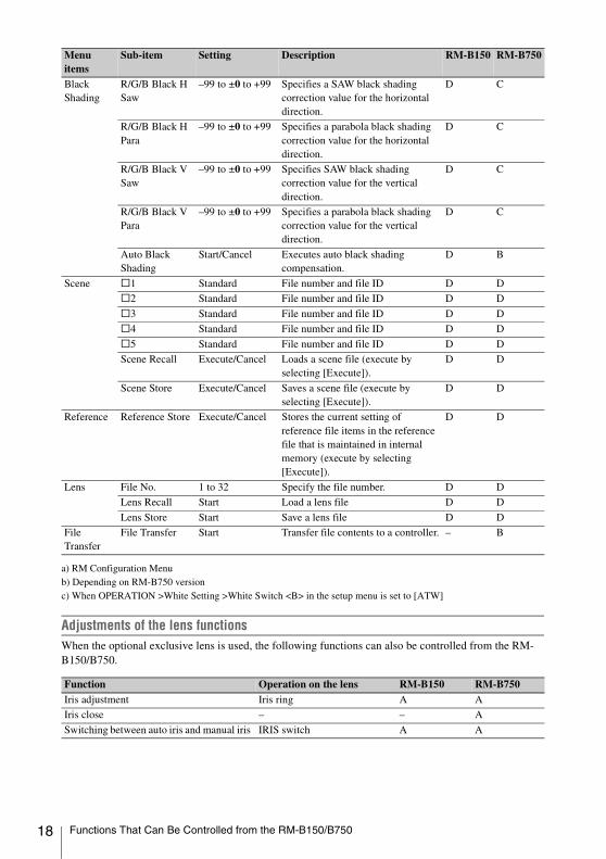
a) RM Configuration Menub) Depending on RM-B750 versionc) When OPERATION >White Setting >White Switch <B> in the setup menu is set to [ATW]
Adjustments of the lens functionsWhen the optional exclusive lens is used, the following functions can also be controlled from the RM-B150/B750.
Black Shading
R/G/B Black H Saw
–99 to ±0 to +99 Specifies a SAW black shading correction value for the horizontal direction.
D C
R/G/B Black H Para
–99 to ±0 to +99 Specifies a parabola black shading correction value for the horizontal direction.
D C
R/G/B Black V Saw
–99 to ±0 to +99 Specifies SAW black shading correction value for the vertical direction.
D C
R/G/B Black V Para
–99 to ±0 to +99 Specifies a parabola black shading correction value for the vertical direction.
D C
Auto Black Shading
Start/Cancel Executes auto black shading compensation.
D B
Scene s1 Standard File number and file ID D D
s2 Standard File number and file ID D D
s3 Standard File number and file ID D D
s4 Standard File number and file ID D D
s5 Standard File number and file ID D D
Scene Recall Execute/Cancel Loads a scene file (execute by selecting [Execute]).
D D
Scene Store Execute/Cancel Saves a scene file (execute by selecting [Execute]).
D D
Reference Reference Store Execute/Cancel Stores the current setting of reference file items in the reference file that is maintained in internal memory (execute by selecting [Execute]).
D D
Lens File No. 1 to 32 Specify the file number. D D
Lens Recall Start Load a lens file D D
Lens Store Start Save a lens file D D
File Transfer
File Transfer Start Transfer file contents to a controller. – B
Function Operation on the lens RM-B150 RM-B750Iris adjustment Iris ring A A
Iris close – – A
Switching between auto iris and manual iris IRIS switch A A
Menu items
Sub-item Setting Description RM-B150 RM-B750
Functions That Can Be Controlled from the RM-B150/B750

Mounting an optional CBK-WA01 Wi-Fi Adapter on this camcorder allows a Wi-Fi connection between a computer and the camcorder.
For details about the CBK-WA01, refer to the Mounting Instructions and Operating Instructions supplied with the CBK-WA01.
Making a Wi-Fi connection between a computer and the camcorder enables you to do the following.• Send planning metadata created on a computer
to the camcorder, and set names of clips to shoot and shot marks for shooting.
• Send files including clips from the camcorder to a computer, and edit them at the shooting location.
• Send audio and video proxy data to a computer and logs it while you are shooting (see page 23).
Notes
• Check the firmware version of your camcorder to make sure that the camcorder supports the Wi-Fi adapter.
For details, contact your Sony dealer or your Sony service representative.
• In order to use the Wi-Fi connection feature, you must install an optional CBK-UPG01 Installation Key.
When installing the CBK-UPG01, refer to the INSTALLATION MANUAL and INSTALLATION GUIDE supplied with the CBK-UPG01.
Notes
• Before attaching or removing the CBK-WA01, turn the power of the camcorder off.
• It may be impossible to stow the camcorder attached with the CBK-WA01 in a carrying case.
1 Attach the Wi-Fi adapter fixing bracket to the camcorder, and fix the bracket with the supplied three screws (A: +B M3×6 screw, B: +B M2.6×5 Type1 screws).
2 Insert the protrusion on the backside of the CBK-WA01 into the hole on the bracket, and tighten the screw to fix the CBK-WA01 to the bracket.
3 Connect the cable of the CBK-WA01 to the external device connector on the camcorder, and store the excess length of the cable in the cable holder.
Using a Wi-Fi Adapter
Fixing the CBK-WA01
Wi-Fi adapter fixing bracket
Using a Wi-Fi Adapter 19

20
Two types of Wi-Fi connections are available. In “ad-hoc mode”, you can make a peer-to-peer Wi-Fi connection between a computer and camcorder. In “infrastructure mode”, you can make Wi-Fi connections between a computer and multiple camcorders via a wireless LAN access point (building a LAN).
To make a network settingChange settings under MAINTENANCE >Network Setting in the setup menu as required.
a) The IP address determined by DHCP server is displayed here.
When you have changed a settingSet the Set item to [Execute]. When a confirmation message appears, turn the MENU knob to select “Execute” and press the knob.
To make a connection in ad hoc mode
1 Refer to “Settings on the Computer” under “Making a Wi-Fi Connection to Your Computer (Ad hoc Mode)” in the Operating Instructions supplied with the CBK-WA01 to make settings on the computer.
2 Start a connection on the computer.
3 Set MAINTENANCE >Wi-Fi Setting >Wi-Fi to [Enable] in the setup menu.
4 Set MAINTENANCE >Wi-Fi Setting >Scan Networks to [Execute] and press the MENU knob.The camcorder starts scanning for a network connection.When networks are detected, the NETWORK SCAN list appears.
5 Turn the MENU knob to select a network and press the knob.The MAINTENANCE menu appears again.
6 Confirm that the settings for the Wi-Fi Setting item conform to the network setting on the computer.SSID (network name): Selected network
nameNetwork Type (connection mode): AdhocCH (channel): 1Authentication (network authentication):
Depending the settings on the computer, Open, Shared or WPA
Making a Wi-Fi Connection
Item SettingDHCP Setting that specifies whether to
acquire the IP address automatically from a DHCP serverEnabled: Acquire automatically.Disabled: Do not acquire
automatically (factory default setting).
IP Address IP address a) (factory default setting: 192.168.1.10)
Subnet Mask Subnet mask (factory default setting: 255.255.255.0)
Default Gateway
Default gateway (factory default setting: 0.0.0.0)
User Name User name for log-in (factory default setting: admin)
Password Password for log-in (factory default setting: model name “pmw-500”)
Cable holder
External device connector
Using a Wi-Fi Adapter

Encryption (data encryption): Depending the settings on the computer, Disable, WEP, TKIP or AES
WEP Key Index (key index): 1 when Encryption is set to [WEP]
Input Select (key input format): Depending the network key (or security key), ASCII5, ASCII13, HEX10 or HEX26 when Encryption is set to [WEP], ASCII8-63 or HEX64 Encryption is set to [TKIP] or [AES]
7 Set the Key item to the network key (or security key) set on the computer and press the MENU knob.
8 Set the Set item to [Execute] and press the MENU knob.The message “Wi-Fi Setting Executing…” appears and the camcorder starts connection. If the connection to the computer is complete, then the message changes to “Wi-Fi Setting OK”. Black squares appear in the Wi-Fi Status column to show the connection status. (The number of squares shows the level of connection status.) In the Wireless Mode column, the IEEE802.11 standard of the established connection appears (802.11b, 802.11g or 802.11n).
Tip
It is also possible to make a connection by accessing a network connection started on the camcorder from the computer.
To terminate the connectionTerminate the connection on the computer.
To revert to the default settings (reset)If you have trouble making a connection, or you want to start over, you can reset your Wi-Fi connection settings to their defaults.
Set MAINTENANCE >Network Setting >Net Config Reset in the setup menu to “Execute” and press the MENU knob.If the reset is executed, the message “Net Config Reset Done” appears.The camcorder attempts to connect to the network using a MAC address as the SSID
To make a connection in infrastructure mode Setting up the wireless LAN access pointThe following settings are required.• Network ID (SSID)• Encryption method• Network key (Key)
For details about setting up the wireless LAN access point.
To find and connect to a wireless LAN from the camcorderPerform the same procedure in “To make a connection in ad hoc mode” (page 20) excluding the following.• Do not perform steps 1 and 2.• The settings made in step 7 change as follows.
SSID (network name): Selected network connection name
Network Type (connection mode): InfraCh (channel): AutoAuthentication (network authentication):
Depending the settings on the computer, Open, Shared, WPA or WPA2
Encryption (data encryption): Depending the settings on the computer, Disable, WEP, TKIP or AES
WEP Key Index (key index): 1 when Encryption is set to [WEP]
Input Select (key input format): Depending the network key (or security key), ASCII5, ASCII13, HEX10 or HEX26 when Encryption is set to [WEP], ASCII8-63 or HEX64 Encryption is set to [TKIP] or [AES]
You can operate the Web menu built in the camcorder from a computer when it is connected to the camcorder via a Wi-Fi connection.
Using the Web Menu
Using a Wi-Fi Adapter 21

22
Example Web menu
Product Information• Model name• Serial No.
Network• MAC Address• IP Address• Subnet Mask
Wi-Fi Status• Wireless Mode• SSID• Type• Channel• Authentication (network authentication)• Data Encryption (data encryption)
Planning MetadataClicking “Upload” displays the Planning Metadata screen which allows upload of a planning metadata file (see page 22).
Note
The configuration of items displayed in the Web menu varies depending on the browser you are using.
To display the Web menu
1 Launch a web browse on the computer, and navigate to “http://<camcorder’s IP address> (setting of Maintenance >Network Setting >IP Address in the setup menu)”.
Example (when the IP address is “192.168.1.10”): Type “http://192.168.1.10/” in the address bar.If the connection is complete, a dialog appears asking you to enter the user name and password.
2 Enter the user name and password, and click [OK].User name: adminPassword: pmw-500 (Lower-case the model
name.)
To upload a planning metadata file
1 Insert a media such as an SxS memory card.
2 Click “Upload” in the Web menu.The Planning Metadata screen appears.
3 Click “Select” to show Choose File dialog.
4 Select the planning metadata file you want to upload, and then click “Open”.The path of the selected file appears.
5 Click “Execute”.The planning metadata file is loaded into the camcorder’s memory and stored in the media.“OK” appears in the Status field when the transfer is complete.
To upload a planning metadata file automaticallyIn the planning metadata file you want to load automatically, add a “load” property to the PlanningMetadata tag and set the value of the property to “True”.When you display the Web menu and insert a media, the planning metadata file is immediately loaded into the camcorder’s memory.
Using a Wi-Fi Adapter

Example: <PlanningMetadata …sp
sp sp spversion="1.00">
For details on the planning metadata, refer to the Operation Manual supplied with the camcorder.
The Live Logging function allows you to transfer proxy AV data to a computer as you are shooting, or to send and receive metadata between this camcorder and a computer.The following operations are available on the computer.• View proxy AV data• Add and edit metadata (titles, comments,
essence marks, and so on)• Create clip listsAfter adding or editing metadata, or creating a clip list, you can transfer the metadata or clip list from the computer back to this unit for recording on the original disc.
There are two Live Logging operating modes.Live mode: You can exchange metadata between
the computer and camcorder during shooting.
View mode: You can send proxy data from the camcorder to the computer, and exchange metadata between them during shooting in Picture Cash mode. (P. Cache Rec Time is fixed to [0-2sec].)
In UDF mode, you can select the mode with OPERATION >Rec Function >Live Logging in the setup menu. In FAT mode, the operation mode is fixed to live mode.
Note
When one of Frame Rec, Interval Rec, and Clip Continuous Rec modes is selected, view mode cannot be selected.
When you install the optional CBK-HD02 SDI/ COMPOSITE Input and 50 Pin Interface in this camcorder, you can output and record input consisting of SDI and composite signals.
To output and record input signals instead of the camera picture, set Operation >Input/Output >Source Select in the setup menu to [External]. You can use Operation >Input/Output > Ext Video Source in the setup menu to select HDSDI signals (HD-SDI), SDSDI signals (SD-SDI) or composite signals (Composite) as intput signals.Use the SDI IN (OPTION) connector to input HDSDI/SDSDI signals, and the GENLOCK IN connector to input composite signals.When you input SDSI signals, you can change the settings of Down Converter, Wide Mode(Ext), and Wide ID to select the signal conversion mode and the method used to handle wide picture information. When you input composite signals, you can use Setup Remove(Ext) to select whether to remove setup.
When i.LINK I/O is set to [Enable], you can simultaneously output HDV/DV signals from the i.LINK(HDV/DV) connector.
Notes
• External input signals cannot be recorded in Frame Rec, Interval Rec, or Slow & Quick Motion mode. When the selected recording mode is any of Frame Rec, Interval Rec, or Slow & Quick Motion mode, that recording mode is cancelled when you set Operation >Input/Output >Source Select in the setup menu to [External].
• External signals cannot be displayed with the Freeze Mix function. Freeze Mix display of the camera picture is cancelled when you set Operation >Input/Output >Source Select in the setup menu to [External].
• Execution of automatic adjustment functions such as automatic black balance and operations such as playback, Rec Review, and thumbnail display ends when set Operation >Input/Output >Source Select in the setup menu to [External]. The camcorder enters stop mode and then the camera picture switches to external input.
Using Live Logging Functions
load="true" Recording External Input (Pool Feed)
Recording External Input (Pool Feed) 23

24
• Recording stops if signal instability occurs during recording of input signals. (Black signals may be recorded before recording stops.) Recording restarts automatically when input signal stability is restored.
• Changing the setting of OPERATION >File System >UDF/FAT in the setup menu resets the Input/Output >Source Select item to [Camera] (factory default setting).
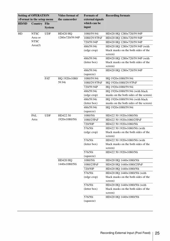
Formats of external signals which can be input and recording formats
Setting of OPERATION >Format in the setup menu
Video format of the camcorder
Formats of external signals which can be input
Recording formats
HD/SD Country File System
HD NTSC Area or NTSC Area(J)
UDF HD422 50 1920×1080/59.94i
1080/59.94i HD422 50 1920×1080/59.94i
1080/29.97PsF HD422 50 1920×1080/29.97PsF
720/59.94P HD422 50 1920×1080/59.94i
486/59.94i (edge crop)
HD422 50 1920×1080/59.94i (with black masks on the both sides of the screen)
486/59.94i (letter box)
HD422 50 1920×1080/59.94i (with black masks on the both sides of the screen)
486/59.94i (squeeze)
HD422 50 1920×1080/59.94i
HD420 HQ 1440×1080/59.94i
1080/59.94i HD420 HQ 1440×1080/59.94i
1080/29.97PsF HD420 HQ 1440×1080/29.97PsF
720/59.94P HD420 HQ 1440×1080/59.94i
486/59.94i (edge crop)
HD420 HQ 1440×1080/59.94i (with black masks on the both sides of the screen)
486/59.94i (letter box)
HD420 HQ 1440×1080/59.94i (with black masks on the both sides of the screen)
486/59.94i (squeeze)
HD420 HQ 1440×1080/59.94i
HD422 50 1280×720/59.94P
1080/59.94i HD422 50 1280×720/59.94P
1080/29.97PsF HD422 50 1280×720/59.94P
720/59.94P HD422 50 1280×720/59.94P
486/59.94i (edge crop)
HD422 50 1280×720/59.94P (with black masks on the both sides of the screen)
486/59.94i (letter box)
HD422 50 1280×720/59.94P (with black masks on the both sides of the screen)
486/59.94i (squeeze)
HD422 50 1280×720/59.94P
Recording External Input (Pool Feed)
HD NTSC Area or NTSC Area(J)
UDF HD420 HQ 1280×720/59.94P
1080/59.94i HD420 HQ 1280×720/59.94P
1080/29.97PsF HD420 HQ 1280×720/59.94P
720/59.94P HD420 HQ 1280×720/59.94P
486/59.94i (edge crop)
HD420 HQ 1280×720/59.94P (with black masks on the both sides of the screen)
486/59.94i (letter box)
HD420 HQ 1280×720/59.94P (with black masks on the both sides of the screen)
486/59.94i (squeeze)
HD420 HQ 1280×720/59.94P
FAT HQ 1920×1080/59.94i
1080/59.94i HQ 1920×1080/59.94i
1080/29.97PsF HQ 1920×1080/29.97PsF
720/59.94P HQ 1920×1080/59.94i
486/59.94i (edge crop)
HQ 1920×1080/59.94i (with black masks on the both sides of the screen)
486/59.94i (letter box)
HQ 1920×1080/59.94i (with black masks on the both sides of the screen)
486/59.94i(squeeze)
HQ 1920×1080/59.94i
PAL Area
UDF HD422 50 1920×1080/50i
1080/50i HD422 50 1920×1080/50i
1080/25PsF HD422 50 1920×1080/25PsF
720/50P HD422 50 1920×1080/50i
576/50i (edge crop)
HD422 50 1920×1080/50i (with black masks on the both sides of the screen)
576/50i (letter box)
HD422 50 1920×1080/50i (with black masks on the both sides of the screen)
576/50i (squeeze)
HD422 50 1920×1080/50i
HD420 HQ 1440×1080/50i
1080/50i HD420 HQ 1440×1080/50i
1080/25PsF HD420 HQ 1440×1080/25PsF
720/50P HD420 HQ 1440×1080/50i
576/50i (edge crop)
HD420 HQ 1440×1080/50i (with black masks on the both sides of the screen)
576/50i (letter box)
HD420 HQ 1440×1080/50i (with black masks on the both sides of the screen)
576/50i (squeeze)
HD420 HQ 1440×1080/50i
Setting of OPERATION >Format in the setup menu
Video format of the camcorder
Formats of external signals which can be input
Recording formats
HD/SD Country File System
Recording External Input (Pool Feed) 25

26
HD PAL Area
UDF HD422 50 1280×720/50P
1080/50i HD422 50 1280×720/50P
1080/25PsF HD422 50 1280×720/50P
720/50P HD422 50 1280×720/50P
576/50i (edge crop)
HD422 50 1280×720/50P (with black masks on the both sides of the screen)
576/50i (letter box)
HD422 50 1280×720/50P (with black masks on the both sides of the screen)
576/50i (squeeze)
HD422 50 1280×720/50P
HD420 HQ 1280×720/50P
1080/50i HD420 HQ 1280×720/50P
1080/25PsF HD420 HQ 1280×720/50P
720/50P HD420 HQ 1280×720/50P
576/50i (edge crop)
HD420 HQ 1280×720/50P (with black masks on the both sides of the screen)
576/50i (letter box)
HD420 HQ 1280×720/50P (with black masks on the both sides of the screen)
576/50i (squeeze)
HD420 HQ 1280×720/50P
FAT HQ 1920×1080/50i 1080/50i HQ 1920×1080/50i
1080/25PsF HQ 1920×1080/25PsF
720/50P HQ 1920×1080/50i
576/50i (edge crop)
HQ 1920×1080/50i (with black masks on the both sides of the screen)
576/50i (letter box)
HQ 1920×1080/50i (with black masks on the both sides of the screen)
576/50i (squeeze)
HQ 1920×1080/50i
Setting of OPERATION >Format in the setup menu
Video format of the camcorder
Formats of external signals which can be input
Recording formats
HD/SD Country File System
Recording External Input (Pool Feed)

SD NTSC Area or NTSC Area(J)
UDF IMX50 59.94i 486/59.94i (edge crop)
IMX50 59.94i (edge crop)
486/59.94i (letter box)
IMX50 59.94i (letter box)
486/59.94i (squeeze)
IMX50 59.94i (squeeze)
IMX50 29.97PsF 486/59.94i (edge crop)
IMX50 59.94i (edge crop)
486/59.94i (letter box)
IMX50 59.94i (letter box)
486/59.94i (squeeze)
IMX50 59.94i (squeeze)
DVCAM 59.94i 486/59.94i (edge crop)
DVCAM 59.94i (edge crop)
486/59.94i (letter box)
DVCAM 59.94i (letter box)
486/59.94i (squeeze)
DVCAM 59.94i (squeeze)
DVCAM 29.97PsF 486/59.94i (edge crop)
DVCAM 59.94i (edge crop)
486/59.94i (letter box)
DVCAM 59.94i (letter box)
486/59.94i {squeeze)
DVCAM 59.94i (squeeze)
FAT DVCAM 59.94i 486/59.94i (edge crop)
DVCAM 59.94i (edge crop)
486/59.94i (letter box)
DVCAM 59.94i (letter box)
486/59.94i (squeeze)
DVCAM 59.94i (squeeze)
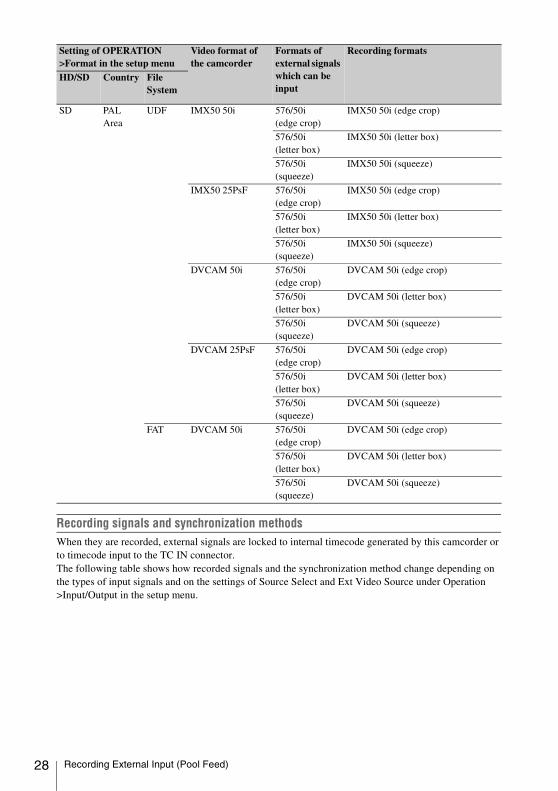
Setting of OPERATION >Format in the setup menu
Video format of the camcorder
Formats of external signals which can be input
Recording formats
HD/SD Country File System
Recording External Input (Pool Feed) 27
28
Recording signals and synchronization methodsWhen they are recorded, external signals are locked to internal timecode generated by this camcorder or to timecode input to the TC IN connector.The following table shows how recorded signals and the synchronization method change depending on the types of input signals and on the settings of Source Select and Ext Video Source under Operation >Input/Output in the setup menu.
SD PAL Area
UDF IMX50 50i 576/50i (edge crop)
IMX50 50i (edge crop)
576/50i (letter box)
IMX50 50i (letter box)
576/50i (squeeze)
IMX50 50i (squeeze)
IMX50 25PsF 576/50i (edge crop)
IMX50 50i (edge crop)
576/50i (letter box)
IMX50 50i (letter box)
576/50i (squeeze)
IMX50 50i (squeeze)
DVCAM 50i 576/50i (edge crop)
DVCAM 50i (edge crop)
576/50i (letter box)
DVCAM 50i (letter box)
576/50i (squeeze)
DVCAM 50i (squeeze)
DVCAM 25PsF 576/50i (edge crop)
DVCAM 50i (edge crop)
576/50i (letter box)
DVCAM 50i (letter box)
576/50i (squeeze)
DVCAM 50i (squeeze)
FAT DVCAM 50i 576/50i (edge crop)
DVCAM 50i (edge crop)
576/50i (letter box)
DVCAM 50i (letter box)
576/50i (squeeze)
DVCAM 50i (squeeze)
Setting of OPERATION >Format in the setup menu
Video format of the camcorder
Formats of external signals which can be input
Recording formats
HD/SD Country File System
Recording External Input (Pool Feed)

Ext. Video Source setting
HD/SD SDI connector input signal
GENLOCK IN connector input signal
Recorded signals Synchronization method
HD-SDI HDSDI Composite or SD-Y HDSDI Genlock to HDSDI signalsHD-Y
None
SDSDI Composite or SD-Y Camera picture Genlock
HD-Y
None No sync
None Composite or SD-Y Genlock
HD-Y
None No sync
SD-SDI HDSDI Composite or SD-Y Camera picture Genlock
HD-Y
None No sync
SDSDI Composite or SD-Y SDSDI Genlock to SDSDI signalsHD-Y
None
None Composite or SD-Y Camera picture Genlock
HD-Y
None No sync
Composite HDSDI Composite or SD-Y Composite or SD-Y Genlock to Composite or SD-Y signals
HD-Y Camera picture Genlock
None No sync
SDSDI Composite or SD-Y Composite or SD-Y Genlock to Composite or SD-Y signals
HD-Y Camera picture Genlock
None No sync
None Composite or SD-Y Composite or SD-Y Genlock to Composite or SD-Y signals
HD-Y Camera picture Genlock
None No sync
Recording External Input (Pool Feed) 29
30
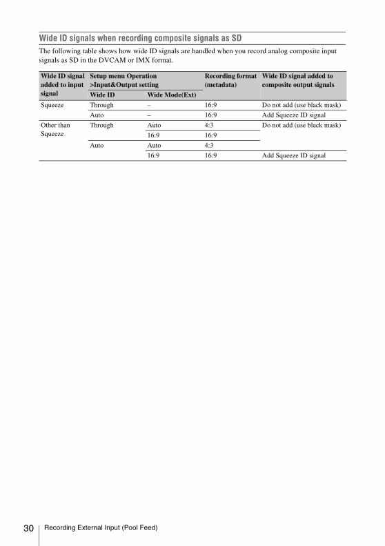
Wide ID signals when recording composite signals as SDThe following table shows how wide ID signals are handled when you record analog composite input signals as SD in the DVCAM or IMX format.
Wide ID signal added to input signal
Setup menu Operation >Input&Output setting
Recording format (metadata)
Wide ID signal added to composite output signals
Wide ID Wide Mode(Ext)
Squeeze Through – 16:9 Do not add (use black mask)
Auto – 16:9 Add Squeeze ID signal
Other than Squeeze
Through Auto 4:3 Do not add (use black mask)
16:9 16:9
Auto Auto 4:3
16:9 16:9 Add Squeeze ID signal
Recording External Input (Pool Feed)

You can make the USER menu easier to use by using the User Menu Customize menu to insert and delete items and to change the order of menu items.You can select any items in the OPERATION, PAINT, and MAINTENANCE menus and insert them into the USER menu. Up to 20 items can be inserted into the USER menu. The USER menu contains six items when the camcorder is shipped from the factory. One of those items cannot be deleted, so you can insert up to 19 items.
The User Menu Customize menu contains the following items.
Note
The same item or sub-item cannot be registered twice. You cannot rename an item or sub-item in the USER menu.
To return the USER menu to the factory default stateSelect [Execute] under the User Menu Customize >Customize Reset, and press the MENU knob.
To insert an item and all sub-items belonging to it
1 Display the User Menu Customize menu.The currently registered items appear. 2 Select the item at the position where you
want to insert a new item, and press the MENU knob.
3 Select [Ins Item R] or [Ins Item r], and press the MENU knob.
Editing the USER Menu
Menu items Sub-item Settings Description
Registered item or Blank (when no item is registered)
Ins Item R Insert an item above the selected item
Ins SubItem R Insert a sub-item above the selected sub-item
Ins Item r Insert an item below the selected item
Ins SubItem r Insert a sub-item below the selected sub-item
Edit Item Del Item/Ins SubItem/Del SubItem
Edit a registered item or sub-itemDel Item: Delete the item Ins SubItem: Insert a sub-itemDel SubItem: Delete a sub-item
Customize Reset Execute/Cancel Return the USER menu to the factory default state (execute by selecting Execute)
Inserting Items and Sub-Items
Editing the USER Menu 31
32
Ins Item R: Insert an item above the selected item.
Ins Item r: Insert an item below the selected item.
A list of items available for insertion appears.
4 Select the item that you want to insert, select [Execute], and press the MENU knob.The selected item and all of its sub-items are inserted at the position specified in steps 2 and 3.
To insert an item and selected sub-item belonging to it
1 Display the User Menu Customize menu.The currently registered items appear.
2 Select the item at the position where you want to insert a new item, and press the MENU knob.
3 Select [Ins SubItem R] or [Ins SubItem r], and press the MENU knob.Ins SubItem R: Insert an item above the
selected item.Ins SubItem r: Insert an item below the
selected item.A list of items available for insertion appears.
4 Select the item that you want to insert, and press the MENU knob.A list of sub-items available for insertion appears.
5 Select the sub-item that you want to insert, select [Execute], and press the MENU knob.The selected item and sub-item are inserted at the position specified in steps 2 and 3.
Note
When you add a sub-item, always add it to the item that it belonged to in the original menu. It is not possible to add a sub-item to a different item.
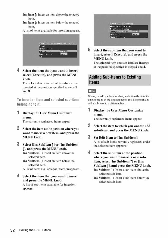
1 Display the User Menu Customize menu.The currently registered items appear.
2 Select the item to which you want to add sub-items, and press the MENU knob.
3 Set Edit Item to [Ins SubItem].A list of sub-items currently registered under the selected item appears.
4 Select the sub-item at the position where you want to insert a new sub-item, select [Ins SubItem R] or [Ins SubItem r], and press the MENU knob.Ins SubItem R: Insert a sub-item above the
selected sub-item.Ins SubItem r: Insert a sub-item below the
selected sub-item.
Adding Sub-Items to Existing Items
Editing the USER Menu

A list of sub-items available for insertion appears.
5 Select the sub-item that you want to insert, select [Execute], and press the MENU knob.The selected sub-item is inserted at the position selected in step 4.
Note
The Camera Config item is registered when the camcorder is shipped from the factory and cannot be deleted.
1 Display the User Menu Customize menu.The currently registered items appear.
2 Select the item that you want to delete, and press the MENU knob.
3 Set Edit Item to [Del Item].The selected item is deleted.
Note
The Camera Config >User Menu Only item is registered when the camcorder is shipped from the factory and cannot be deleted.
1 Display the User Menu Customize menu.The currently registered items appear.
2 Select the item that contains the sub-item you want to delete, and press the MENU knob.
3 Set Edit Item to [Del SubItem].
A list of sub-items available for deletion appears.
4 Select the sub-item that you want to delete, and press the MENU knob.The selected sub-item is deleted.
Deleting Items
Deleting Sub-Items
Editing the USER Menu 33

34
The format of signals output from the VIDEO OUT, and HD/SD SDI OUT connectors varies according to the HD/SD mode, the current recording and playback video formats, and the output signal specified by OPERATION >Input/Output >Output in the setup menu. (Depending on the above conditions, some limitations may also apply to signal output and input.)
Video formats and output signals, as specified by Input/Output settings (when OPERATION >Format >Country is set to [NTSC Area] or [NTSC Area(J)])
Output Formats and Limitations
Video Formats and Output Signals (for UDF Mode)
UDF
Video format Input/Output settings Output signal
Output 23.98P Output SDI OUT VIDEO OUT
HD4221920×1080/59.94i HQ1440x1080/59.94i
HD 1920×1080/59.94i 1920×1080/59.94i Y signal
SD – 720×480/59.94i Composite720×480/59.94i
HD4221920×1080/29.97PHQ1440×1080/29.97P
HD – 1920×1080/29.97PsF 1920×1080/29.97PsF Y signal
SD – 720×480/29.97PsF Composite720×480/29.97PsF
HD422 1920×1080/23.98PHQ 1440×1080/23.98P
HD PsF 1920×1080/23.98PsF 1920×1080/23.98PsF Y signal
Pull Down 1920×1080/59.94i2:3 pull down
1920×1080/59.94i2:3 pull down Y signal
SD 720×480/59.94i2:3 pull down
Composite720×480/59.94i2:3 pull down
HD422 1280×720/59.94P
HD 1280×720/59.94P 1280×720/59.94P Y signal
SD 720×480/59.94i Composite720×480/59.94i
HD422 1280×720/29.97P
HD 1280×720/59.94P 1280×720/59.94P Y signal
SD 720×480/29.97PsF Composite720×480/29.97PsF
HD4221280×720/23.98P
HD 1280×720/59.94P2:3 pull down
Composite1280×720/59.94P2:3 pull down
SD 720×480/59.94i2:3 pull down
Composite720×480/59.94i2:3 pull down
Output Formats and Limitations

Video formats and output signals, as specified by Input/Output settings (when OPERATION >Format >Country is set to [PAL Area])
The format of signals output from the VIDEO OUT, and HD/SD SDI OUT connectors varies according to the HD/SD mode, the current recording and playback video formats, and the output signal specified by OPERATION >Input/Output >Output & i.LINK in the setup menu. (Depending on the above conditions, some limitations may also apply to signal output and input.)
IMX 512/59.94iDVCAM 480/59.94i
SD 720×480/59.94i Composite720×480/59.94i
IMX 512/29.97PDVCAM 480/29.97P
SD 720×480/29.97PsF Composite720×480/29.97PsF
Video format Input/Output settings Output signal
Output 23.98P Output SDI OUT VIDEO OUT
HD422 1920×1080/50iHQ 1440×1080/50i
HD 1920×1080/50i 1920×1080/50i Y signal
SD – 720×480/50i Composite720×480/50i
HD4221920×1080/25PHQ1440×1080/25P
HD – 1920×1080/25PsF 1920×1080/25PsF Y signal
SD – 720×480/25PsF Composite720×480/25PsF
HD422 1280×720/50P
HD – 1280×720/50P 1280×720/50P Y signal
SD – 720×480/50i Composite720×480/50i
HD422 1280×720/25P
HD – 1280×720/50P 1280×720/50P Y signal
SD – 720×480/25PsF Composite720×480/25PsF
IMX 608/50iDVCAM 480/50i
SD – 720×480/50i Composite720×480/50i
IMX 608/25PDVCAM 480/25P
SD – 720×480/25PsF Composite720×480/25PsF
Video format Input/Output settings Output signal
Output 23.98P Output SDI OUT VIDEO OUT
Video Formats and Output Signals (for FAT Mode)
FAT
Output Formats and Limitations 35

36
Video formats and output signals, as specified by Input/Output settings (when OPERATION >Format >Country is set to [NTSC Area] or [NTSC Area(J)])
Video format
Input/Output settings Output signal (i.LINK (HDV/DV) is I/O signal)
Output&i.LINK
23.98P Output
Source Select
i.LINK I/O
HD/SD SDI OUT
VIDEO OUT i.LINK (HDV/DV)
HQ 1920×1080/59.94iHQ 1440×1080/59.94i
HD&HDV – i.LINK Enable Muting Input/output disabledCamera Enable 1920×1080/
59.94i1920×1080/59.94i Y signalCamera/
i.LINKDisable
SD&HDV – i.LINK Enable Muting
Camera Enable 720×480/59.94i Composite 720×480/59.94iCamera/
i.LINKDisable
SD&DV – i.LINK Enable 720×480/59.94i Composite 720×480/59.94i
DV (720×480/59.94i)Camera Enable
Camera/i.LINK
Disable Input/output disabled
SP 1440×1080/59.94i
HD&HDV – i.LINK Enable 1920×1080/59.94i
1920×1080/59.94i Y signal
HDV (1440×1080/59.94i)
Camera Enable
Camera/i.LINK
Disable Input/output disabled
SD&HDV – i.LINK Enable 720×480/59.94i Composite 720×480/59.94i
HDV (1440×1080/59.94i)
Camera Enable
Camera/i.LINK
Disable Input/output disabled
SD&DV – i.LINK Enable 720×480/59.94i Composite 720×480/59.94i
DV (720×480/59.94i)Camera Enable
Camera/i.LINK
Disable Input/output disabled
HQ 1920×1080/29.97PHQ 1440×1080/29.97P
HD&HDV – i.LINK Enable Muting Input/output disabledCamera Enable 1920×1080/
29.97PsF1920×1080/29.97PsF Y signal
Camera/i.LINK
Disable
SD&HDV – i.LINK Enable Muting
Camera Enable 720×480/29.97PsF
Composite 720×480/29.97PsF
Camera/i.LINK
Disable
SD&DV – i.LINK Enable 720×480/29.97PsF
Composite 720×480/29.97PsF
DV (720×480/29.97PsF)Camera Enable
Camera/i.LINK
Disable Input/output disabled
Output Formats and Limitations
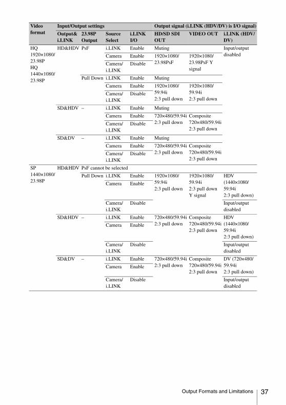
HQ 1920×1080/23.98PHQ 1440×1080/23.98P
HD&HDV PsF i.LINK Enable Muting Input/output disabledCamera Enable 1920×1080/
23.98PsF1920×1080/23.98PsF Y signal
Camera/i.LINK
Disable
Pull Down i.LINK Enable Muting
Camera Enable 1920×1080/59.94i2:3 pull down
1920×1080/59.94i2:3 pull down
Camera/i.LINK
Disable
SD&HDV – i.LINK Enable Muting
Camera Enable 720×480/59.94i2:3 pull down
Composite 720×480/59.94i2:3 pull down
Camera/i.LINK
Disable
SD&DV – i.LINK Enable Muting
Camera Enable 720×480/59.94i2:3 pull down
Composite 720×480/59.94i2:3 pull down
Camera/i.LINK
Disable
SP1440×1080/23.98P
HD&HDV PsF cannot be selected
Pull Down i.LINK Enable 1920×1080/59.94i2:3 pull down
1920×1080/59.94i2:3 pull down Y signal
HDV (1440×1080/59.94i2:3 pull down)
Camera Enable
Camera/i.LINK
Disable Input/output disabled
SD&HDV – i.LINK Enable 720×480/59.94i2:3 pull down
Composite 720×480/59.94i2:3 pull down
HDV (1440×1080/59.94i2:3 pull down)
Camera Enable
Camera/i.LINK
Disable Input/output disabled
SD&DV – i.LINK Enable 720×480/59.94i2:3 pull down
Composite 720×480/59.94i2:3 pull down
DV (720×480/59.94i2:3 pull down)
Camera Enable
Camera/i.LINK
Disable Input/output disabled
Video format
Input/Output settings Output signal (i.LINK (HDV/DV) is I/O signal)
Output&i.LINK
23.98P Output
Source Select
i.LINK I/O
HD/SD SDI OUT
VIDEO OUT i.LINK (HDV/DV)
Output Formats and Limitations 37
38
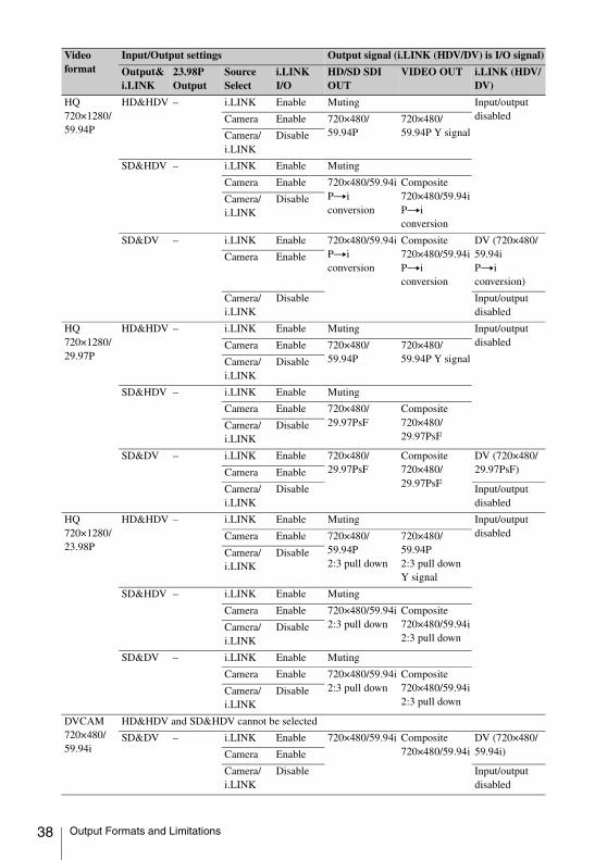
HQ 720×1280/59.94P
HD&HDV – i.LINK Enable Muting Input/output disabledCamera Enable 720×480/
59.94P720×480/59.94P Y signalCamera/
i.LINKDisable
SD&HDV – i.LINK Enable Muting
Camera Enable 720×480/59.94iPti conversion
Composite 720×480/59.94iPti conversion
Camera/i.LINK
Disable
SD&DV – i.LINK Enable 720×480/59.94iPti conversion
Composite 720×480/59.94iPti conversion
DV (720×480/59.94iPti conversion)
Camera Enable
Camera/i.LINK
Disable Input/output disabled
HQ720×1280/29.97P
HD&HDV – i.LINK Enable Muting Input/output disabledCamera Enable 720×480/
59.94P720×480/59.94P Y signalCamera/
i.LINKDisable
SD&HDV – i.LINK Enable Muting
Camera Enable 720×480/29.97PsF
Composite 720×480/29.97PsF
Camera/i.LINK
Disable
SD&DV – i.LINK Enable 720×480/29.97PsF
Composite 720×480/29.97PsF
DV (720×480/29.97PsF)Camera Enable
Camera/i.LINK
Disable Input/output disabled
HQ720×1280/23.98P
HD&HDV – i.LINK Enable Muting Input/output disabledCamera Enable 720×480/
59.94P2:3 pull down
720×480/59.94P2:3 pull down Y signal
Camera/i.LINK
Disable
SD&HDV – i.LINK Enable Muting
Camera Enable 720×480/59.94i2:3 pull down
Composite 720×480/59.94i2:3 pull down
Camera/i.LINK
Disable
SD&DV – i.LINK Enable Muting
Camera Enable 720×480/59.94i2:3 pull down
Composite 720×480/59.94i2:3 pull down
Camera/i.LINK
Disable
DVCAM720×480/59.94i
HD&HDV and SD&HDV cannot be selected
SD&DV – i.LINK Enable 720×480/59.94i Composite 720×480/59.94i
DV (720×480/59.94i)Camera Enable
Camera/i.LINK
Disable Input/output disabled
Video format
Input/Output settings Output signal (i.LINK (HDV/DV) is I/O signal)
Output&i.LINK
23.98P Output
Source Select
i.LINK I/O
HD/SD SDI OUT
VIDEO OUT i.LINK (HDV/DV)
Output Formats and Limitations

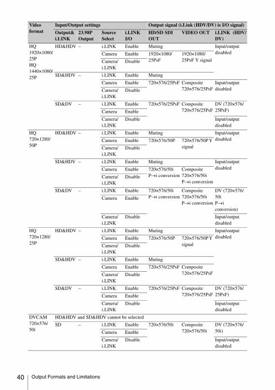
Video formats and output signals, as specified by Input/Output settings (when OPERATION >Format >Country is set to [PAL Area])
DVCAM720×480/29.97P
HD&HDV and SD&HDV cannot be selected
SD&DV i.LINK Enable 720×480/29.97PsF
Composite 720×480/29.97PsF
DV (720×480/29.97PsF)Camera Enable
Camera/i.LINK
Disable Input/output disabled
480P cannot be selected
Video format
Input/Output settings Output signal (i.Link (HDV/DV) is I/O signal)
Output&i.LINK
23.98P Output
Source Select
i.LINK I/O
HD/SD SDI OUT
VIDEO OUT i.LINK (HDV/DV)
HQ 1920×1080/50iHQ 1440×1080/50i
HD&HDV – i.LINK Enable Muting Input/output disabledCamera Enable 1920×1080/50i 1920×1080/50i
Y signalCamera/i.LINK
Disable
SD&HDV – i.LINK Enable Muting Input/output disabledCamera Enable 720×576/50i Composite
720×576/50iCamera/i.LINK
Disable
SD&DV – i.LINK Enable 720×576/50i Composite 720×576/50i
DV (720×576/50i)Camera Enable
Camera/i.LINK
Disable Input/output disabled
SP 1440×1080/50i
HD&HDV – i.LINK Enable 1920×1080/50i 1920×1080/50i Y signal
HDV (1440×1080/50i)Camera Enable
Camera/i.LINK
Disable Input/output disabled
SD&HDV – i.LINK Enable 720×576/50i Composite 720×576/50i
HDV (1440×1080/50i)Camera Enable
Camera/i.LINK
Disable Input/output disabled
SD&DV – i.LINK Enable 720×576/50i Composite 720×576/50i
DV (720×576/50i)Camera Enable
Camera/i.LINK
Disable Input/output disabled
Video format
Input/Output settings Output signal (i.LINK (HDV/DV) is I/O signal)
Output&i.LINK
23.98P Output
Source Select
i.LINK I/O
HD/SD SDI OUT
VIDEO OUT i.LINK (HDV/DV)
Output Formats and Limitations 39
40
HQ 1920×1080/25PHQ1440×1080/25P
HD&HDV – i.LINK Enable Muting Input/output disabledCamera Enable 1920×1080/
25PsF1920×1080/25PsF Y signalCamera/
i.LINKDisable
SD&HDV – i.LINK Enable Muting
Camera Enable 720×576/25PsF Composite 720×576/25PsF
Input/output disabledCamera/
i.LINKDisable
SD&DV – i.LINK Enable 720×576/25PsF Composite 720×576/25PsF
DV (720×576/25PsF)Camera Enable
Camera/i.LINK
Disable Input/output disabled
HQ720×1280/50P
HD&HDV – i.LINK Enable Muting Input/output disabledCamera Enable 720×576/50P 720×576/50P Y
signalCamera/i.LINK
Disable
SD&HDV – i.LINK Enable Muting Input/output disabledCamera Enable 720×576/50i
P→i conversionComposite 720×576/50iP→i conversion
Camera/i.LINK
Disable
SD&DV – i.LINK Enable 720×576/50iP→i conversion
Composite 720×576/50iP→i conversion
DV (720×576/50iP→i conversion)
Camera Enable
Camera/i.LINK
Disable Input/output disabled
HQ720×1280/25P
HD&HDV – i.LINK Enable Muting Input/output disabledCamera Enable 720×576/50P 720×576/50P Y
signalCamera/i.LINK
Disable
SD&HDV – i.LINK Enable Muting
Camera Enable 720×576/25PsF Composite 720×576/25PsFCamera/
i.LINKDisable
SD&DV – i.LINK Enable 720×576/25PsF Composite 720×576/25PsF
DV (720×576/25PsF)Camera Enable
Camera/i.LINK
Disable Input/output disabled
DVCAM720×576/50i
HD&HDV and SD&HDV cannot be selected
SD – i.LINK Enable 720×576/50i Composite 720×576/50i
DV (720×576/50i)Camera Enable
Camera/i.LINK
Disable Input/output disabled
Video format
Input/Output settings Output signal (i.Link (HDV/DV) is I/O signal)
Output&i.LINK
23.98P Output
Source Select
i.LINK I/O
HD/SD SDI OUT
VIDEO OUT i.LINK (HDV/DV)
Output Formats and Limitations

DVCAM720×576/25P
HD&HDV and SD&HDV cannot be selected
SD – i.LINK Enable 720×576/25PsF Composite 720×576/25PsF
DV (720×576/50i)Camera Enable
Camera/i.LINK
Disable Input/output disabled
Video format
Input/Output settings Output signal (i.Link (HDV/DV) is I/O signal)
Output&i.LINK
23.98P Output
Source Select
i.LINK I/O
HD/SD SDI OUT
VIDEO OUT i.LINK (HDV/DV)
Output Formats and Limitations 41

The material contained in this manual consists of information that is the property of Sony Corporation and is intended solely for use by the purchasers of the equipment described in this manual.Sony Corporation expressly prohibits the duplication of any portion of this manual or the use thereof for any purpose other than the operation or maintenance of the equipment described in this manual without the express written permission of Sony Corporation.

PMW-500(SY)4-260-138-02(1)
Sony Corporation© 2010