
SOLID-STATE HIGH VOLTAGE MODULATOR AND ITS · PDF fileSOLID-STATE HIGH VOLTAGE MODULATOR AND...
18
GA–A26129 SOLID-STATE HIGH VOLTAGE MODULATOR AND ITS APPLICATION TO RF SOURCE HIGH VOLTAGE POWER SUPPLIES by J.F. TOOKER, P. HUYNH, and R.W. STREET JULY 2008
Transcript of SOLID-STATE HIGH VOLTAGE MODULATOR AND ITS · PDF fileSOLID-STATE HIGH VOLTAGE MODULATOR AND...

GA–A26129
SOLID-STATE HIGH VOLTAGE MODULATOR AND ITS APPLICATION TO RF SOURCE HIGH VOLTAGE
POWER SUPPLIES by
J.F. TOOKER, P. HUYNH, and R.W. STREET
JULY 2008

DISCLAIMER
This report was prepared as an account of work sponsored by an agency of the United States Government. Neither the United States Government nor any agency thereof, nor any of their employees, makes any warranty, express or implied, or assumes any legal liability or responsibility for the accuracy, completeness, or usefulness of any information, apparatus, product, or process disclosed, or represents that its use would not infringe privately owned rights. Reference herein to any specific commercial product, process, or service by trade name, trademark, manufacturer, or otherwise, does not necessarily constitute or imply its endorsement, recommendation, or favoring by the United States Government or any agency thereof. The views and opinions of authors expressed herein do not necessarily state or reflect those of the United States Government or any agency thereof.
GA– A26129
SOLID-STATE HIGH VOLTAGE MODULATOR AND ITS APPLICATION TO RF SOURCE HIGH VOLTAGE
POWER SUPPLIES by
J.F. TOOKER, P. HUYNH, and R.W. STREET
This is a preprint of a paper to be presented at the 25th Symposium on Fusion Technology, September 15-19, 2008, in Rostock, Germany, and to be published in the Proceedings.
Work supported by the U.S. Department of Energy under DE-FC02-04ER54698
and by the U.S. Air Force under FA9451-05-D-0004
GENERAL ATOMICS PROJECT 30200 JULY 2008
SOLID-STATE HIGH VOLTAGE MODULATOR AND ITS APPLICATION TO RF SOURCE HIGH VOLTAGE POWER SUPPLIES J.F. Tooker, et al.
GENERAL ATOMICS REPORT GA-A26129 iii
ABSTRACT
A solid-state high voltage modulator is described in which series-connected insulated-gate bipolar transistors (IGBTs) are switched at a fixed frequency by a pulse width modulation (PWM) regulator, that adjusts the pulse width to control the voltage out of an inductor-capacitor filter network. General Atomics proposed the HV power supply (HVPS) topology of multiple IGBT modulators connected to a common HVdc source for the large number of 1 MW klystrons in the linear accelerator of the Accelerator Production of Tritium project. The switching of 24 IGBTs to obtain 20 kVdc at 20 A for short pulses was successfully demonstrated. This effort was incorporated into the design of a , 80 A, IGBT modulator, and in a short-pulse test 12 IGBTs regulated -5 kV at 50 A under PWM control. These two tests confirm the practicality of solid-state IGBT modulators to regulate high voltage at reasonable currents.
Tokamaks such as ITER require large rf heating and current drive systems with multiple rf sources. A HVPS topology is presented that readily adapts to the three rf heating systems on ITER. To take advantage of the known economy of scale for power conversion equipment, a single HVdc source feeds multiple rf sources. The large power conversion equipment, which is located outside, converts the incoming utility line voltage directly to the HVdc needed for the class of rf sources connected to it, to further reduce cost. The HVdc feeds a set of IGBT modulators, one for each rf source, to independently control the voltage applied to each source, maximizing operational flexibility. Only the modulators are indoors, close to the rf sources, minimizing the use of costly near-tokamak floor space.

SOLID-STATE HIGH VOLTAGE MODULATOR AND ITS APPLICATION TO RF SOURCE HIGH VOLTAGE POWER SUPPLIES J.F. Tooker, et al.
GENERAL ATOMICS REPORT GA-A26129 1
I. INTRODUCTION
Each of the rf heating and current drive (H&CD) systems on ITER has multiple rf sources. The electron cyclotron (EC) system has twenty-four 170 GHz gyrotrons [1], the ion cyclotron (IC) system has eight amplifiers with two tetrodes each [2], the lower hybrid (LH) system would have 24 klystrons [3], and there are plans for future upgrades of each. Traditional practice would have a single power supply for each rf source with approximately -70 kV output for a gyrotron, 25 kV for a tetrode, or -95 kV for a klystron. While this results in a power system having the most versatility to operate the rf sources, it also results in a system that has the highest cost and would occupy the most space, specifically near the tokamak, where space comes at a high premium. Because these rf systems are very large, one would like to take advantage of the known economy of scale to reduce their cost and size by connecting more than one rf source to the same but larger power supply, which the options under consideration for the ITER rf power systems are attempting to do. One option for the EC system (baseline design of 2001 ITER design [4]) has two large HVdc power supplies with twelve gyrotrons connected to it in pairs through six IGBT switches. This has the advantage of a lower-cost large power supply, but the disadvantage that the twelve gyrotrons connected to it have the same voltage applied to them, which presents operational disadvantages. A second option [1] has twelve pulse-step modulated (PSM) power supplies [5] with two gyrotrons connected to each. This option, essentially one power supply per pair of gyrotrons, has increased versatility to operate the gyrotrons compared to the first option. However, it still has the operational issues of two gyrotrons on a common supply.
There are also concerns over space used by these large power systems, especially with regard to the more costly indoor floor space. The closer to the tokamak this space is, the more valuable it becomes. The devices that ultimately apply or control the high voltage to the rf sources (solid-state switch, modulator, IGBTs, etc) must be located as close as reasonably possible to the rf sources to minimize the energy stored in the high voltage cable between the controlling device and the rf source, thereby reducing the energy that could be deposited into a fault in the rf source. The bulky AC-to-DC power conversion equipment can and should be located farther away, such as outdoors. The physical configuration for the PSM power supplies has the step-up transformers located next to the racks containing the IGBT modules because of the large number of interconnecting high voltage cables. All this equipment is proposed to be located in a room below the gyrotrons. The space to support this equipment is not insignificant, and additional space is needed for the AC distribution bus and circuit breakers to supply the AC power to each PSM.

SOLID-STATE HIGH VOLTAGE MODULATOR AND ITS J.F. Tooker, et al. APPLICATION TO RF SOURCE HIGH VOLTAGE POWER SUPPLIES
2 GENERAL ATOMICS REPORT GA-A26129
In order to obtain the most cost-effective power systems, the design must consider the entire system from the AC utility line to the rf source, including floor space utilization. To take advantage of the known economy of scale for power systems, one power system should have multiple rf sources connected to it. To maximize the versatility needed to support the required operational functionality, as well as off-line troubleshooting and conditioning of the rf sources, the power system must have the capability to control the voltage applied to each rf source individually. A system configuration that places the bulky power conversion equipment far from the tokamak (preferably outdoors) will minimize the use of the more costly near-tokamak indoor floor space.
An additional path to make the system more cost-effective is to convert the AC line voltage directly to the required HVdc. In the second EC power supply option proposed for ITER with PSMs, the line voltage (69 kVAC) is stepped down to an intermediate AC voltage first (20 kVAC). For the same twelve rf sources, this requires the same circuit breaker and essentially the same transformer as option one, but with a different turns ratio for the secondary windings. This is followed by the AC bus to distribute this intermediate voltage to six PSMs with their six sets of circuit breakers, multi-secondary transformers, and multiple rectifier and filter networks to generate the high voltage. It is easy to see that this configuration is more costly than the first option because of the intermediate AC distribution bus and six sets of circuit breakers and multi-secondary transformers that are not needed in the first option. In addition, the single, higher-capacity rectifier stack and filter in the first option are likely to be less costly than the six sets of rectifier and filter networks in the second option.
SOLID-STATE HIGH VOLTAGE MODULATOR AND ITS APPLICATION TO RF SOURCE HIGH VOLTAGE POWER SUPPLIES J.F. Tooker, et al.
GENERAL ATOMICS REPORT GA-A26129 3
II. BACKGROUND OF HVPS TOPOLOGY
Series strings of diodes have been used for decades to rectify the output of high voltage transformers to obtain HVdc. More recently, other solid-state power semiconductors are being used in series in a variety of high voltage applications. For example, series-connected SCRs (Silicon Controlled Rectifiers) are being used in crowbars [6] as a replacement for ignitrons. Series-connected IGBTs are in use as fast on-off high voltage switches [7].
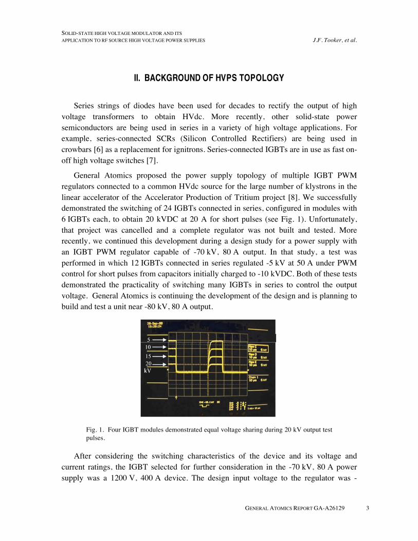
General Atomics proposed the power supply topology of multiple IGBT PWM regulators connected to a common HVdc source for the large number of klystrons in the linear accelerator of the Accelerator Production of Tritium project [8]. We successfully demonstrated the switching of 24 IGBTs connected in series, configured in modules with 6 IGBTs each, to obtain 20 kVDC at 20 A for short pulses (see Fig. 1). Unfortunately, that project was cancelled and a complete regulator was not built and tested. More recently, we continued this development during a design study for a power supply with an IGBT PWM regulator capable of -70 kV, 80 A output. In that study, a test was performed in which 12 IGBTs connected in series regulated -5 kV at 50 A under PWM control for short pulses from capacitors initially charged to -10 kVDC. Both of these tests demonstrated the practicality of switching many IGBTs in series to control the output voltage. General Atomics is continuing the development of the design and is planning to build and test a unit near -80 kV, 80 A output.
Fig. 1. Four IGBT modules demonstrated equal voltage sharing during 20 kV output test pulses.
After considering the switching characteristics of the device and its voltage and current ratings, the IGBT selected for further consideration in the -70 kV, 80 A power supply was a 1200 V, 400 A device. The design input voltage to the regulator was -

SOLID-STATE HIGH VOLTAGE MODULATOR AND ITS J.F. Tooker, et al. APPLICATION TO RF SOURCE HIGH VOLTAGE POWER SUPPLIES
4 GENERAL ATOMICS REPORT GA-A26129
85 kVDC at full load, -95 kVDC no-load. The design had 104 IGBTs in series to hold off this voltage and not overstress the IGBTs even with multiple failed IGBTs. Circuitries were included to ensure static and dynamic voltage sharing of the IGBTs and also to detect a failed IGBT and inhibit operation.
A physical layout was developed in which the IGBT assembly was modularized. Four IGBTs were assembled into a module as shown in Fig. 2 and twenty-six modules made up the full assembly of IGBTs. Three of the modules were used in the tests mentioned above. The IGBTs are mounted on water-cooled heat sinks, using six liters per minute to remove an estimated 1350 watts of conduction and switching losses from the four IGBTs.
Fig. 2. Assembled IGBT modules successfully demonstrated proper high voltage switching.
SOLID-STATE HIGH VOLTAGE MODULATOR AND ITS APPLICATION TO RF SOURCE HIGH VOLTAGE POWER SUPPLIES J.F. Tooker, et al.
GENERAL ATOMICS REPORT GA-A26129 5
III. RF SOURCE HVPS OVERVIEW
One possible topology of high voltage power supplies for the rf systems that could satisfy the operational requirements in a cost-effective manner is to have multiple regulators, one for each rf source, connected to a common HVdc source. The HVdc source would derive its power from the 69 kVAC line, without using an intermediate AC voltage, and consist of switchgear, a transformer-rectifier, and a filter. The output voltage of this HVdc source would be appropriate for the class of rf sources connected to it (approximately -70 kV for the EC gyrotrons, 25 kV for the tetrodes of the IC system, and -95 kV for the klystrons for the LH system), plus a few kilovolts above these respective values to give the regulator the voltage headroom it will need to operate properly.
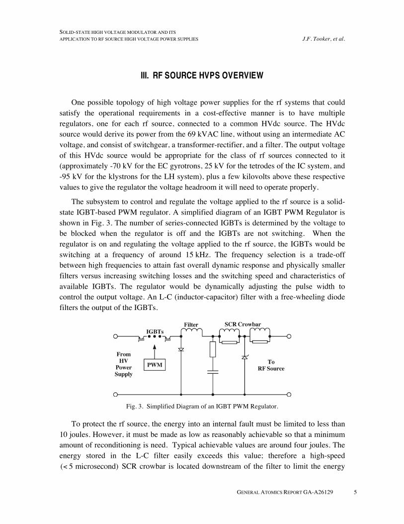
The subsystem to control and regulate the voltage applied to the rf source is a solid-state IGBT-based PWM regulator. A simplified diagram of an IGBT PWM Regulator is shown in Fig. 3. The number of series-connected IGBTs is determined by the voltage to be blocked when the regulator is off and the IGBTs are not switching. When the regulator is on and regulating the voltage applied to the rf source, the IGBTs would be switching at a frequency of around 15 kHz. The frequency selection is a trade-off between high frequencies to attain fast overall dynamic response and physically smaller filters versus increasing switching losses and the switching speed and characteristics of available IGBTs. The regulator would be dynamically adjusting the pulse width to control the output voltage. An L-C (inductor-capacitor) filter with a free-wheeling diode filters the output of the IGBTs.
Fig. 3. Simplified Diagram of an IGBT PWM Regulator.
To protect the rf source, the energy into an internal fault must be limited to less than 10 joules. However, it must be made as low as reasonably achievable so that a minimum amount of reconditioning is need. Typical achievable values are around four joules. The energy stored in the L-C filter easily exceeds this value; therefore a high-speed
SCR crowbar is located downstream of the filter to limit the energy
SOLID-STATE HIGH VOLTAGE MODULATOR AND ITS J.F. Tooker, et al. APPLICATION TO RF SOURCE HIGH VOLTAGE POWER SUPPLIES
6 GENERAL ATOMICS REPORT GA-A26129
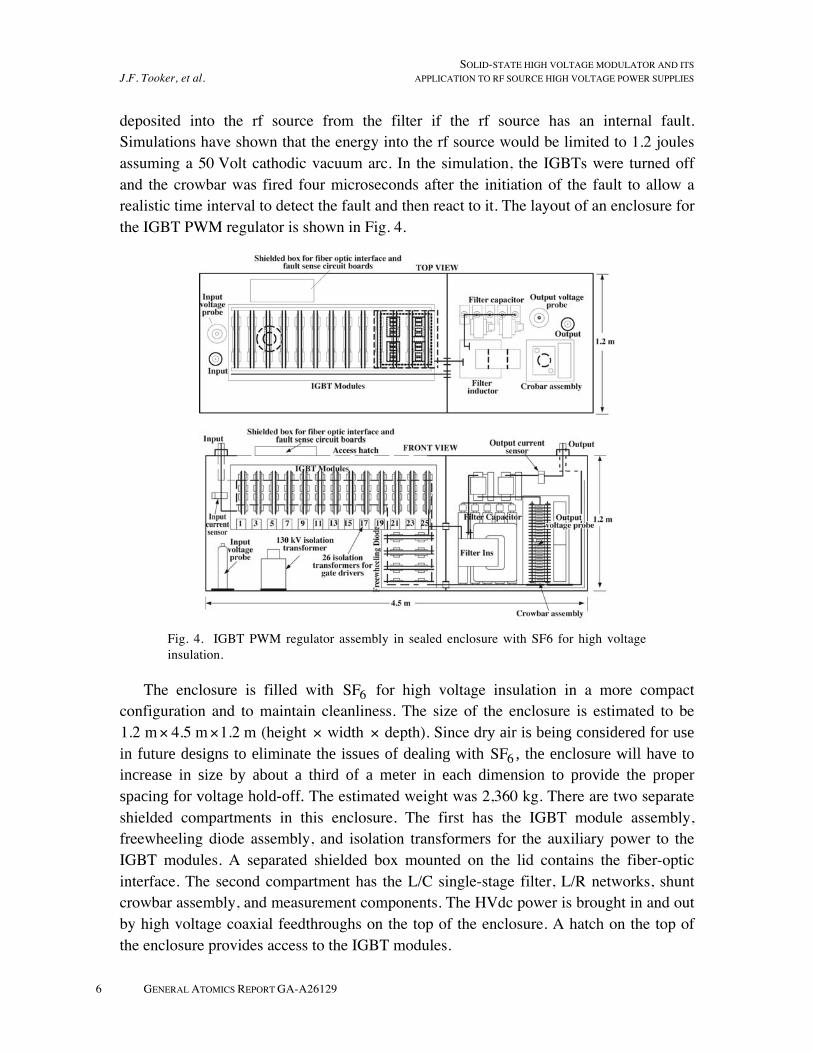
deposited into the rf source from the filter if the rf source has an internal fault. Simulations have shown that the energy into the rf source would be limited to 1.2 joules assuming a 50 Volt cathodic vacuum arc. In the simulation, the IGBTs were turned off and the crowbar was fired four microseconds after the initiation of the fault to allow a realistic time interval to detect the fault and then react to it. The layout of an enclosure for the IGBT PWM regulator is shown in Fig. 4.
Fig. 4. IGBT PWM regulator assembly in sealed enclosure with SF6 for high voltage insulation.
The enclosure is filled with SF6 for high voltage insulation in a more compact configuration and to maintain cleanliness. The size of the enclosure is estimated to be 1.2 m 4.5 m 1.2 m (height width depth). Since dry air is being considered for use
in future designs to eliminate the issues of dealing with SF6 , the enclosure will have to
increase in size by about a third of a meter in each dimension to provide the proper
spacing for voltage hold-off. The estimated weight was 2,360 kg. There are two separate shielded compartments in this enclosure. The first has the IGBT module assembly, freewheeling diode assembly, and isolation transformers for the auxiliary power to the IGBT modules. A separated shielded box mounted on the lid contains the fiber-optic interface. The second compartment has the L/C single-stage filter, L/R networks, shunt crowbar assembly, and measurement components. The HVdc power is brought in and out by high voltage coaxial feedthroughs on the top of the enclosure. A hatch on the top of the enclosure provides access to the IGBT modules.
SOLID-STATE HIGH VOLTAGE MODULATOR AND ITS APPLICATION TO RF SOURCE HIGH VOLTAGE POWER SUPPLIES J.F. Tooker, et al.
GENERAL ATOMICS REPORT GA-A26129 7
IV. PHYSICAL LAYOUT OF RF HVPS
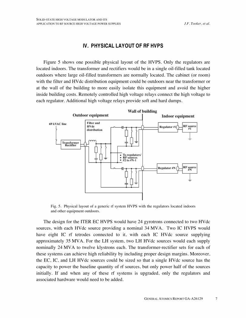
Figure 5 shows one possible physical layout of the HVPS. Only the regulators are located indoors. The transformer and rectifiers would be in a single oil-filled tank located outdoors where large oil-filled transformers are normally located. The cabinet (or room) with the filter and HVdc distribution equipment could be outdoors near the transformer or at the wall of the building to more easily isolate this equipment and avoid the higher inside building costs. Remotely controlled high voltage relays connect the high voltage to each regulator. Additional high voltage relays provide soft and hard dumps.
Fig. 5. Physical layout of a generic rf system HVPS with the regulators located indoors and other equipment outdoors.
The design for the ITER EC HVPS would have 24 gyrotrons connected to two HVdc sources, with each HVdc source providing a nominal 34 MVA. Two IC HVPS would have eight IC rf tetrodes connected to it, with each IC HVdc source supplying approximately 35 MVA. For the LH system, two LH HVdc sources would each supply nominally 24 MVA to twelve klystrons each. The transformer-rectifier sets for each of these systems can achieve high reliability by including proper design margins. Moreover, the EC, IC, and LH HVdc sources could be sized so that a single HVdc source has the capacity to power the baseline quantity of rf sources, but only power half of the sources initially. If and when any of these rf systems is upgraded, only the regulators and associated hardware would need to be added.
SOLID-STATE HIGH VOLTAGE MODULATOR AND ITS APPLICATION TO RF SOURCE HIGH VOLTAGE POWER SUPPLIES J.F. Tooker, et al.
GENERAL ATOMICS REPORT GA-A26129 9
V. ITER EC HVPS
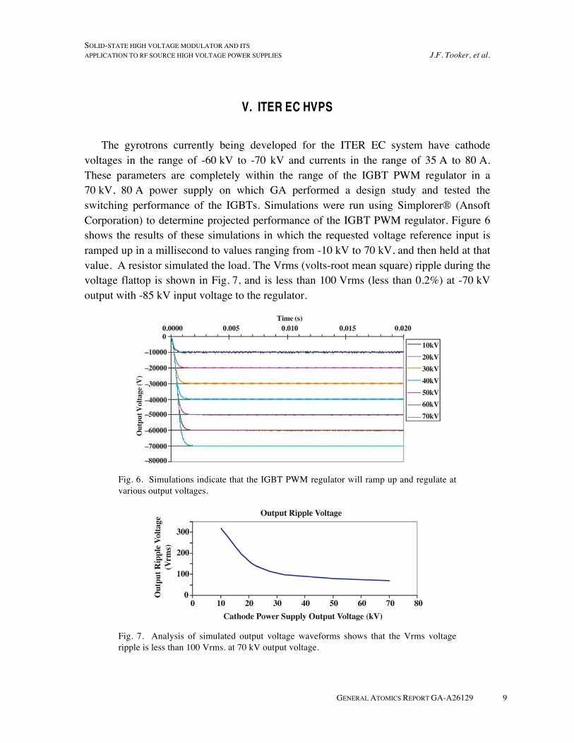
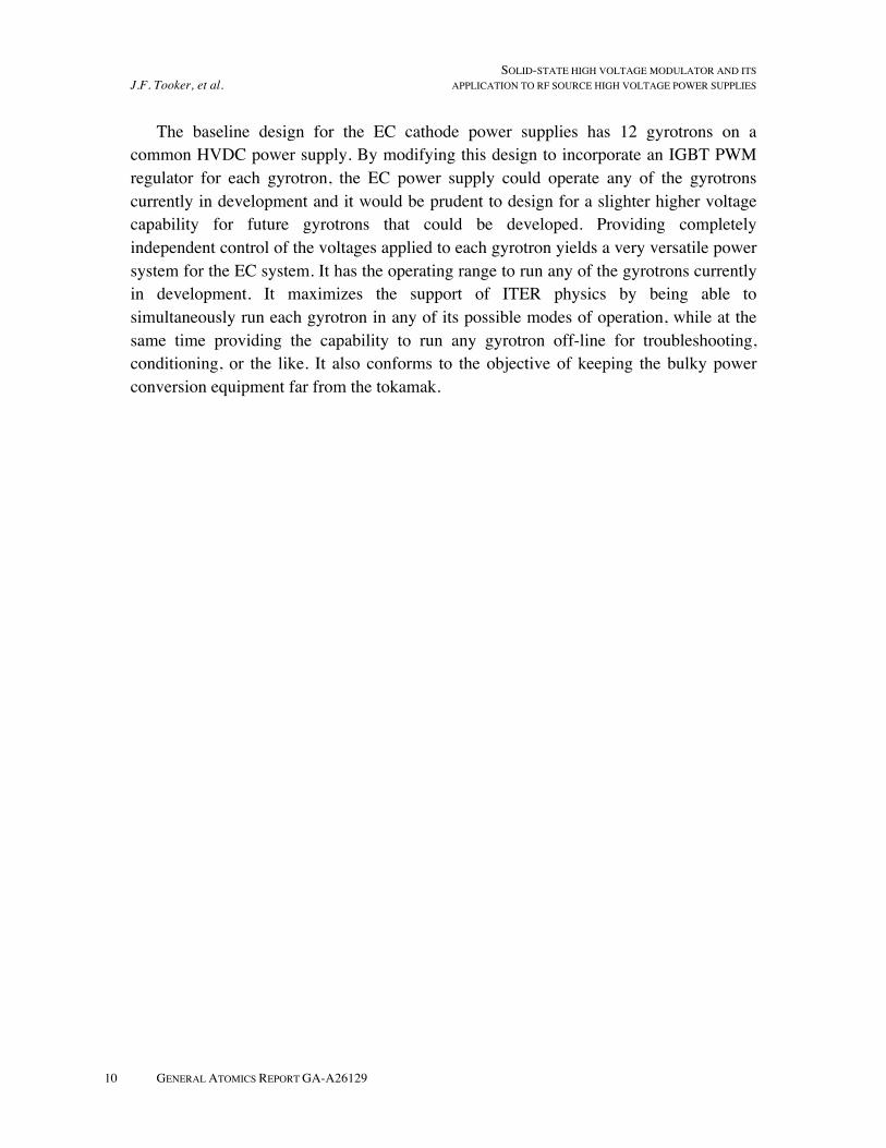
The gyrotrons currently being developed for the ITER EC system have cathode voltages in the range of -60 kV to -70 kV and currents in the range of 35 A to 80 A. These parameters are completely within the range of the IGBT PWM regulator in a 70 kV, 80 A power supply on which GA performed a design study and tested the switching performance of the IGBTs. Simulations were run using Simplorer® (Ansoft Corporation) to determine projected performance of the IGBT PWM regulator. Figure 6 shows the results of these simulations in which the requested voltage reference input is ramped up in a millisecond to values ranging from -10 kV to 70 kV, and then held at that value. A resistor simulated the load. The Vrms (volts-root mean square) ripple during the voltage flattop is shown in Fig. 7, and is less than 100 Vrms (less than 0.2%) at -70 kV output with -85 kV input voltage to the regulator.
Fig. 6. Simulations indicate that the IGBT PWM regulator will ramp up and regulate at various output voltages.
Fig. 7. Analysis of simulated output voltage waveforms shows that the Vrms voltage ripple is less than 100 Vrms. at 70 kV output voltage.
SOLID-STATE HIGH VOLTAGE MODULATOR AND ITS J.F. Tooker, et al. APPLICATION TO RF SOURCE HIGH VOLTAGE POWER SUPPLIES
10 GENERAL ATOMICS REPORT GA-A26129
The baseline design for the EC cathode power supplies has 12 gyrotrons on a common HVDC power supply. By modifying this design to incorporate an IGBT PWM regulator for each gyrotron, the EC power supply could operate any of the gyrotrons currently in development and it would be prudent to design for a slighter higher voltage capability for future gyrotrons that could be developed. Providing completely independent control of the voltages applied to each gyrotron yields a very versatile power system for the EC system. It has the operating range to run any of the gyrotrons currently in development. It maximizes the support of ITER physics by being able to simultaneously run each gyrotron in any of its possible modes of operation, while at the same time providing the capability to run any gyrotron off-line for troubleshooting, conditioning, or the like. It also conforms to the objective of keeping the bulky power conversion equipment far from the tokamak.
SOLID-STATE HIGH VOLTAGE MODULATOR AND ITS APPLICATION TO RF SOURCE HIGH VOLTAGE POWER SUPPLIES J.F. Tooker, et al.
GENERAL ATOMICS REPORT GA-A26129 11
VI. ITER IC HVPS
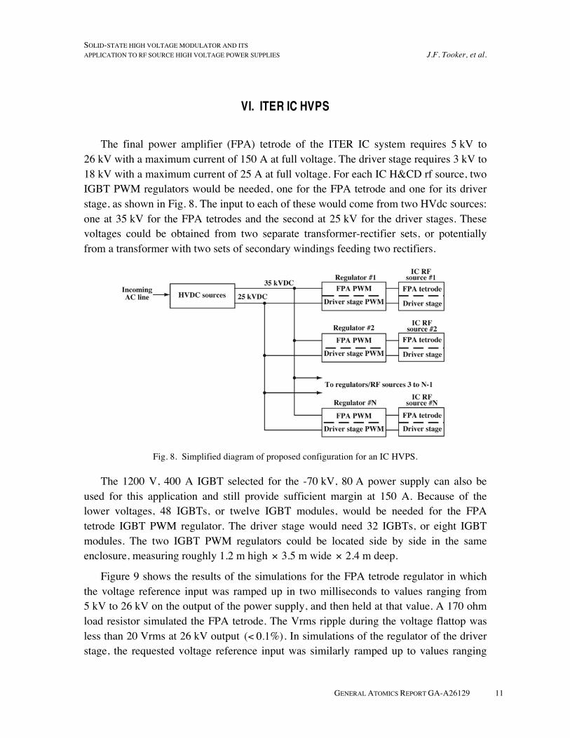
The final power amplifier (FPA) tetrode of the ITER IC system requires 5 kV to 26 kV with a maximum current of 150 A at full voltage. The driver stage requires 3 kV to 18 kV with a maximum current of 25 A at full voltage. For each IC H&CD rf source, two IGBT PWM regulators would be needed, one for the FPA tetrode and one for its driver stage, as shown in Fig. 8. The input to each of these would come from two HVdc sources: one at 35 kV for the FPA tetrodes and the second at 25 kV for the driver stages. These voltages could be obtained from two separate transformer-rectifier sets, or potentially from a transformer with two sets of secondary windings feeding two rectifiers.
Fig. 8. Simplified diagram of proposed configuration for an IC HVPS.
The 1200 V, 400 A IGBT selected for the -70 kV, 80 A power supply can also be used for this application and still provide sufficient margin at 150 A. Because of the lower voltages, 48 IGBTs, or twelve IGBT modules, would be needed for the FPA tetrode IGBT PWM regulator. The driver stage would need 32 IGBTs, or eight IGBT modules. The two IGBT PWM regulators could be located side by side in the same enclosure, measuring roughly 1.2 m high 3.5 m wide 2.4 m deep.
Figure 9 shows the results of the simulations for the FPA tetrode regulator in which the voltage reference input was ramped up in two milliseconds to values ranging from 5 kV to 26 kV on the output of the power supply, and then held at that value. A 170 ohm load resistor simulated the FPA tetrode. The Vrms ripple during the voltage flattop was less than 20 Vrms at 26 kV output . In simulations of the regulator of the driver stage, the requested voltage reference input was similarly ramped up to values ranging

SOLID-STATE HIGH VOLTAGE MODULATOR AND ITS J.F. Tooker, et al. APPLICATION TO RF SOURCE HIGH VOLTAGE POWER SUPPLIES
12 GENERAL ATOMICS REPORT GA-A26129
from 3 kV to 18 kV, and then held at that value. A 720 ohm load resistor simulated the driver stage. The Vrms ripple during the voltage flattop was approximately 17 Vrms at 18 kV output.
Fig. 9. Simulations show that the FPA tetrode IGBT PWM regulator will ramp up and regulate at various output voltages from 5 kV to 26 kV.

SOLID-STATE HIGH VOLTAGE MODULATOR AND ITS APPLICATION TO RF SOURCE HIGH VOLTAGE POWER SUPPLIES J.F. Tooker, et al.
GENERAL ATOMICS REPORT GA-A26129 13
VII. SUMMARY
A HVPS topology is presented for the ITER rf sources that maximizes the flexibility of rf source operation while minimizing cost and minimizing the use of near-tokamak floor space. To take advantage of the known economy of scale for power conversion equipment, multiple rf sources are fed from a single HVdc source. The large AC-to HVdc power conversion equipment is located outside. To further reduce cost, this power conversion equipment converts the incoming utility AC line voltage directly to the HVdc needed for the class of rf sources connected to it. The HVdc is fed to a set of IGBT PWM regulators, one for each rf source, so that the voltage applied to each can be independently controlled, thereby maximizing the operational flexibility of the rf system. Only the regulators are indoors, close to the rf sources, occupying the minimum amount of costly near-tokamak floor space. The topology is readily adaptable to the three rf heating systems on ITER, which can save design costs, and reduce operational costs due to commonality of parts.

SOLID-STATE HIGH VOLTAGE MODULATOR AND ITS APPLICATION TO RF SOURCE HIGH VOLTAGE POWER SUPPLIES J.F. Tooker, et al.
GENERAL ATOMICS REPORT GA-A26129 15
REFERENCES
[1] M.A. Henderson, et al., “Critical Interfaces associated with the ITER EC System,” Nucl. Fusion 48 (2008)
[2] J. Hosea, et al., “RF Sources for the ITER Ion Cyclotron Heating and Current Drive System,” 21st IEEE/NPSS Symposium on Fusion Engineering (SOFE), Knoxville, Sept. 26-29, 2005
[3] Ph. Bibet, et al., “ITER LHCD Plans and Design,” 21st IEEE/NPSS Symposium on Fusion Engineering (SOFE), Knoxville, Sept. 26-29, 2005
[4] ITER Technical Basis, July 2001, available from www.iter.org
[5] W. Forster, et al., “High Voltage, High Power, Pulse-Step Modulators for the Accurate Supply of Gyrotron and other Heating Devices,” Conference Record of the Twenty-Fifth International Power Modulator Symposium, 30 June-3 July 2002 Page(s): 126 - 129
[6] R.L. Cassel, “A 95 kV klystron power supply crowbar using light triggered SCR,” 2004 IEEE International Power Modulator Symposium and High Voltage Workshop, 23-26 May 2004, San Francisco, California.
[7] T. Fujii, et al., “Operational progress of the 110GHz-4MW ECRF heating system in JT-60U,” Third IAEA Technical Meeting on ECRH Physics and Technology in ITER, 2–5 May 2005, Como, Italy.
[8] R. Street, et al., “Advanced Buck Converter Power Supply ‘ABCPS’ for APT,” Proceedings of the Linac98 Conference, 23-28 August 1998, Chicago, Illinois.
SOLID-STATE HIGH VOLTAGE MODULATOR AND ITS APPLICATION TO RF SOURCE HIGH VOLTAGE POWER SUPPLIES J.F. Tooker, et al.
GENERAL ATOMICS REPORT GA-A26129 17
ACKNOWLEDGMENTS
Work supported by the U.S. Department of Energy under DE-FC02-04ER54698 and by the U.S. Air Force Research Laboratory under FA9451-05-D-0004.