Solenoid Operated Poppet-Type Directional Valvepub/@eaton/@hyd/documents/co… · F-2 EATON...
12
DG3VP-3, DG4VP-3, CVUA-6 20 Design Solenoid operated poppet type directional valve ISO4401 SIZE 03; ANSI/B93.7M-D03 DG3/4VP-3 Gasket Mounted Model CVUA-6-PD- Cartridge Model
Transcript of Solenoid Operated Poppet-Type Directional Valvepub/@eaton/@hyd/documents/co… · F-2 EATON...

DG3VP-3, DG4VP-3, CVUA-6 20 Design Solenoid operated poppet type directional valve
ISO4401 SIZE 03; ANSI/B93.7M-D03
DG3/4VP-3 Gasket Mounted Model CVUA-6-PD- Cartridge Model

EATON INDUSTRIAL VALVES E-VLVI-SS001-E1—January 2018 www.eaton.com2
1
2
31
3
5
6
7
8
1
10
1
1
1
1
1
1
1
1
1
1
1
1
1
1
1
1
1
1
1
1
Table of content
Introduction . . . . . . . . . . . . . . . . . . . . . . . . . . . . . . . . . . . . . . . . . . . . . . . . . . . . . 03
Model code . . . . . . . . . . . . . . . . . . . . . . . . . . . . . . . . . . . . . . . . . . . . . . . . . . . . . 04
Operating data . . . . . . . . . . . . . . . . . . . . . . . . . . . . . . . . . . . . . . . . . . . . . . . . . . 06
Performance graphs . . . . . . . . . . . . . . . . . . . . . . . . . . . . . . . . . . . . . . . . . . . . . . 07
Installation Dimensions . . . . . . . . . . . . . . . . . . . . . . . . . . . . . . . . . . . . . . . . . . . 08
Recess dimensions . . . . . . . . . . . . . . . . . . . . . . . . . . . . . . . . . . . . . . . . . . . . . . . 10
EATON INDUSTRIAL VALVES E-VLVI-SS001-E1—January 2018 www.eaton.com 3
1
2
3
4
5
6
7
8
1
10
1
1
1
1
1
1
1
1
1
1
1
1
1
1
1
1
1
1
1
1
Solenoid operated poppet type directional valveDG3/4VP-3 Gasket Mounted Model CVUA-6-PD- Cartridge Model
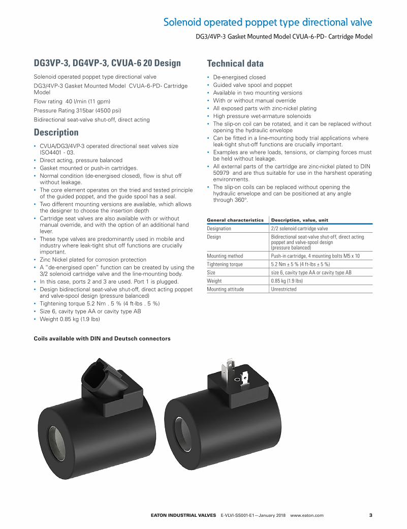
DG3VP-3, DG4VP-3, CVUA-6 20 DesignSolenoid operated poppet type directional valve
DG3/4VP-3 Gasket Mounted Model CVUA-6-PD- Cartridge Model
Flow rating 40 l/min (11 gpm)
Pressure Rating 315bar (4500 psi)
Bidirectional seat-valve shut-off, direct acting
Description• CVUA/DG3/4VP-3 operated directional seat valves size
ISO4401 - 03. • Direct acting, pressure balanced• Gasket mounted or push-in cartridges. • Normal condition (de-energised closed), flow is shut off
without leakage. • The core element operates on the tried and tested principle
of the guided poppet, and the guide spool has a seal. • Two different mounting versions are available, which allows
the designer to choose the insertion depth • Cartridge seat valves are also available with or without
manual override, and with the option of an additional hand lever.
• These type valves are predominantly used in mobile and industry where leak-tight shut off functions are crucially important.
• Zinc Nickel plated for corrosion protection• A “de-energised open” function can be created by using the
3/2 solenoid cartridge valve and the line-mounting body. • In this case, ports 2 and 3 are used. Port 1 is plugged. • Design bidirectional seat-valve shut-off, direct acting poppet
and valve-spool design (pressure balanced) • Tightening torque 5.2 Nm . 5 % (4 ft-lbs . 5 %) • Size 6, cavity type AA or cavity type AB • Weight 0.85 kg (1.9 lbs)
Coils available with DIN and Deutsch connectors
Technical data• De-energised closed • Guided valve spool and poppet • Available in two mounting versions • With or without manual override • All exposed parts with zinc-nickel plating • High pressure wet-armature solenoids • The slip-on coil can be rotated, and it can be replaced without
opening the hydraulic envelope • Can be fitted in a line-mounting body trial applications where
leak-tight shut-off functions are crucially important. • Examples are where loads, tensions, or clamping forces must
be held without leakage. • All external parts of the cartridge are zinc-nickel plated to DIN
50979 and are thus suitable for use in the harshest operating environments.
• The slip-on coils can be replaced without opening the hydraulic envelope and can be positioned at any angle through 360°.
General characteristics Description, value, unit
Designation 2/2 solenoid cartridge valve
Design Bidirectional seat-valve shut-off, direct acting poppet and valve-spool design (pressure balanced)
Mounting method Push-in cartridge, 4 mounting bolts M5 x 10
Tightening torque 5.2 Nm ± 5 % (4 ft-lbs ± 5 %)
Size size 6, cavity type AA or cavity type AB
Weight 0.85 kg (1.9 lbs)
Mounting attitude Unrestricted
EATON INDUSTRIAL VALVES E-VLVI-SS001-E1—January 2018 www.eaton.com4
1
2
31
3
5
6
7
8
1
10
1
1
1
1
1
1
1
1
1
1
1
1
1
1
1
1
1
1
1
1
1
(F3) M
64
*— V
5
— *
7
— *
8
— —
9
-20DG*VP-3
2
—
3
10**—
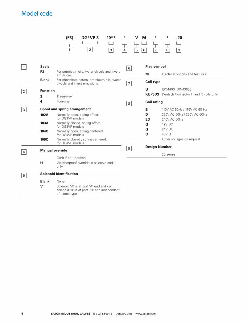
1 SealsF3 For petroleum oils, water glycols and invert
emulsionsBlank For phosphate esters, petroleum oils, water
glycols and invert emulsions
2 Function
3 Three-way
4 Four-way
3 Spool and spring arrangement
102A Normally open, spring offset, for DG3VP models
103A Normally closed, spring offset, for DG3VP models
104C Normally open, spring centered, for DG4VP models
105C Normally closed , spring centered, for DG4VP models
4 Manual override
Omit if not required
H Weatherproof override in solenoid ends only
5 Solenoid identification
Blank None
V Solenoid "A" is at port "A" end and / or solenoid "B" is at port "B" end independent of spool type
6 Flag symbol
M Electrical options and features.
7 Coil type
U ISO4400, DIN43650
KUP5D3 Deutsch Connector H and G coils only
8 Coil rating
B 110V AC 50Hz / 115V AC 60 Hz
D 220V AC 50Hz / 230V AC 60Hz
ED 240V AC 50Hz
G 12V DC
G 24V DC
O 48V DOther voltages on request
9 Design Number
20 series
Model code
EATON INDUSTRIAL VALVES E-VLVI-SS001-E1—January 2018 www.eaton.com 5
1
2
3
4
5
6
7
8
1
10
1
1
1
1
1
1
1
1
1
1
1
1
1
1
1
1
1
1
1
1
3
*
1
(F3)
4
*— M
5
— *
7
—U
6
— 20
8
—CVUA-6-PD
2
—
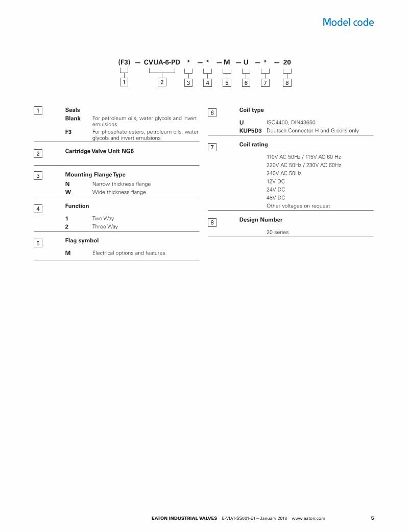
1 SealsBlank For petroleum oils, water glycols and invert
emulsionsF3 For phosphate esters, petroleum oils, water
glycols and invert emulsions
2 Cartridge Valve Unit NG6
3 Mounting Flange Type
N Narrow thickness flange
W Wide thickness flange
4 Function
1 Two Way
2 Three Way
5 Flag symbol
M Electrical options and features.
6 Coil type
U ISO4400, DIN43650
KUP5D3 Deutsch Connector H and G coils only
7 Coil rating
110V AC 50Hz / 115V AC 60 Hz220V AC 50Hz / 230V AC 60Hz240V AC 50Hz12V DC24V DC48V DCOther voltages on request
8 Design Number
20 series
Model code
EATON INDUSTRIAL VALVES E-VLVI-SS001-E1—January 2018 www.eaton.com6
1
2
31
3
5
6
7
8
1
10
1
1
1
1
1
1
1
1
1
1
1
1
1
1
1
1
1
1
1
1
Operating data
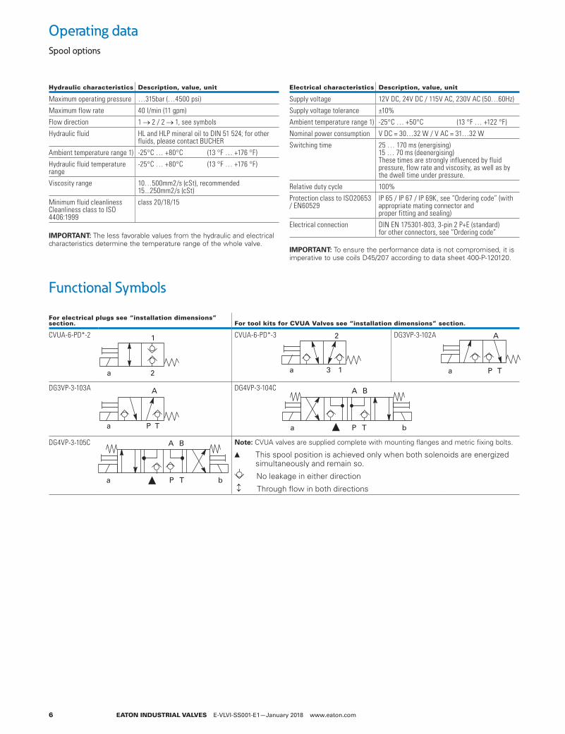
Functional Symbols
Spool options
Hydraulic characteristics Description, value, unit
Maximum operating pressure …315 bar (…4500 psi)
Maximum flow rate 40 l/min (11 gpm)
Flow direction 1 2 / 2 1, see symbols
Hydraulic fluid HL and HLP mineral oil to DIN 51 524; for other fluids, please contact BUCHER
Ambient temperature range 1) -25°C … +80°C (13 °F … +176 °F)
Hydraulic fluid temperature range
-25°C … +80°C (13 °F … +176 °F)
Viscosity range 10…500 mm2/s (cSt), recommended 15...250 mm2/s (cSt)
Minimum fluid cleanliness Cleanliness class to ISO 4406:1999
class 20/18/15
Electrical characteristics Description, value, unit
Supply voltage 12V DC, 24V DC / 115V AC, 230V AC (50…60Hz)
Supply voltage tolerance ±10%
Ambient temperature range 1) -25°C … +50°C (13 °F … +122 °F)
Nominal power consumption V DC = 30…32 W / V AC = 31…32 W
Switching time 25 … 170 ms (energising)15 … 70 ms (deenergising)These times are strongly influenced by fluid pressure, flow rate and viscosity, as well as bythe dwell time under pressure.
Relative duty cycle 100%
Protection class to ISO20653 / EN60529
IP 65 / IP 67 / IP 69K, see “Ordering code” (with appropriate mating connector andproper fitting and sealing)
Electrical connection DIN EN 175301-803, 3-pin 2 P+E (standard)for other connectors, see “Ordering code”
For electrical plugs see “installation dimensions” section. For tool kits for CVUA Valves see “installation dimensions” section.
CVUA-6-PD*-2 1
a 2
CVUA-6-PD*-3
1
2
a 3
DG3VP-3-102A
a
A
P T
DG3VP-3-103A
a
A
P T
DG4VP-3-104C
P T ba
A B
DG4VP-3-105C
P T ba
A B otee:N CVUA valves are supplied complete with mounting flanges and metric fixing bolts.
▲ This spool position is achieved only when both solenoids are energized simultaneously and remain so.
No leakage in either direction
Through flow in both directions
MPORTANTe:I The less favorable values from the hydraulic and electrical characteristics determine the temperature range of the whole valve.
MPORTANTe:I To ensure the performance data is not compromised, it is imperative to use coils D45/207 according to data sheet 400-P-120120.
EATON INDUSTRIAL VALVES E-VLVI-SS001-E1—January 2018 www.eaton.com 7
1
2
3
4
5
6
7
8
1
10
1
1
1
1
1
1
1
1
1
1
1
1
1
1
1
1
1
1
1
1
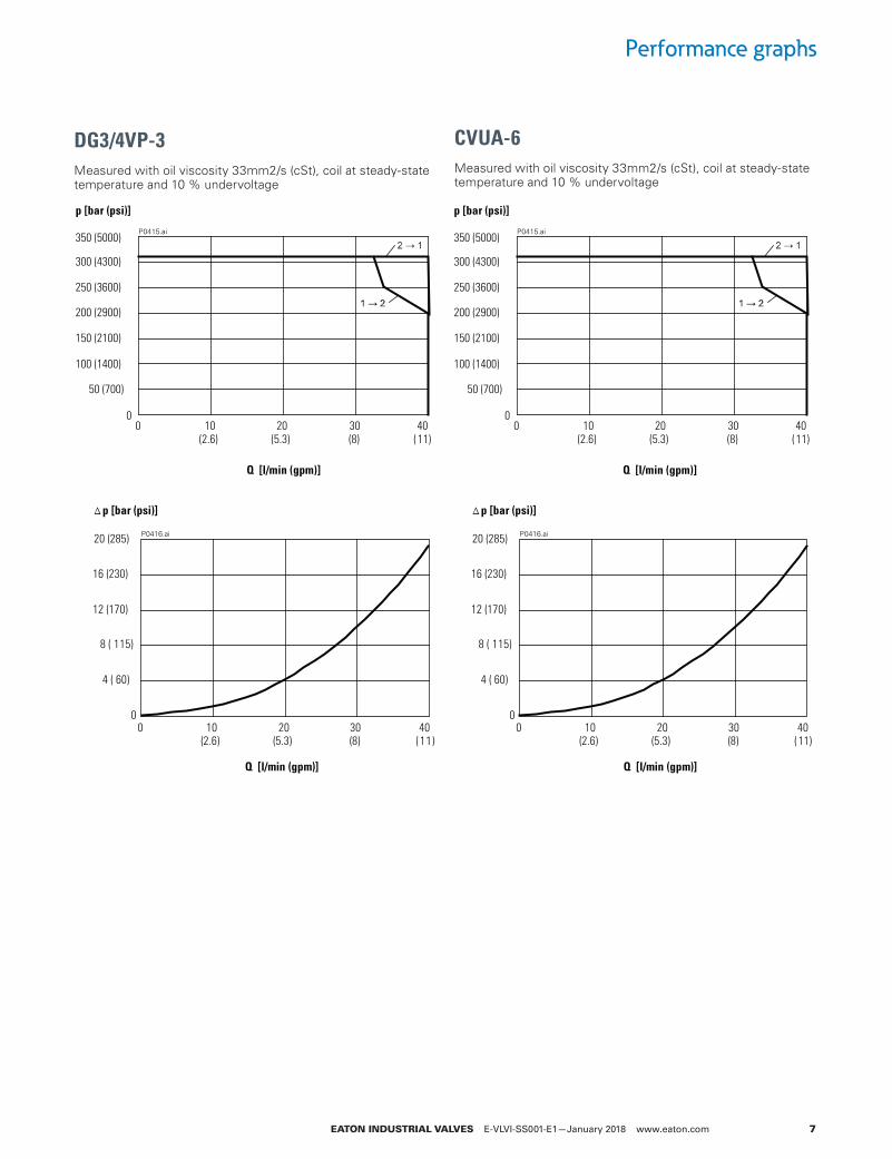
Performance graphs
DG3/4VP-3Measured with oil viscosity 33mm2/s (cSt), coil at steady-state temperature and 10 % undervoltage
CVUA-6Measured with oil viscosity 33mm2/s (cSt), coil at steady-state temperature and 10 % undervoltage
P0415.ai
0
50 (700)
100 (1400)
150 (2100)
200 (2900)
250 (3600)
300 (4300)
350 (5000)
Q [l/min (gpm)]
403020100
p [bar (psi)]
( 11)(8)(5.3)(2.6)
P0416.ai
0
4 ( 60)
8 ( 115)
12 (170)
16 (230)
20 (285)
Q [l/min (gpm)]
403020100
p [bar (psi)]
( 11)(8)(5.3)(2.6)
P0415.ai
0
50 (700)
100 (1400)
150 (2100)
200 (2900)
250 (3600)
300 (4300)
350 (5000)
Q [l/min (gpm)]
403020100
p [bar (psi)]
( 11)(8)(5.3)(2.6)
P0416.ai
0
4 ( 60)
8 ( 115)
12 (170)
16 (230)
20 (285)
Q [l/min (gpm)]
403020100
p [bar (psi)]
( 11)(8)(5.3)(2.6)
EATON INDUSTRIAL VALVES E-VLVI-SS001-E1—January 2018 www.eaton.com8
1
2
31
3
5
6
7
8
1
10
1
1
1
1
1
1
1
1
1
1
1
1
1
1
1
1
1
1
1
1
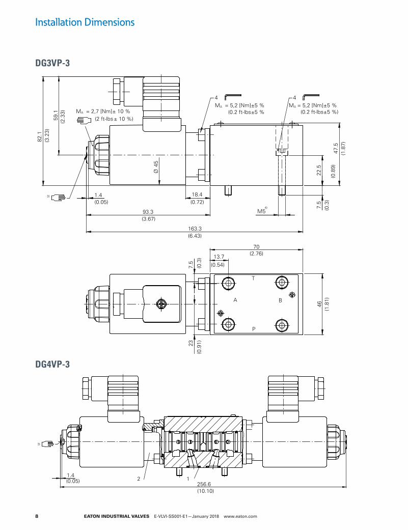
1.4(0.05)
93.3
18.4
7.5
22.5
47.5
82.1
59.1
163.3
70
13.7
23
46(1
.81)
7.5
4 4
A B
T
P
MA = 5,2 [Nm]±5 %
3)
M54)
Ø45
MA = 2,7 [Nm]± 10 %MA = 5,2 [Nm]±5 %
(2 ft-lbs± 10 %)(2.3
3)
(3.2
3)
(3.67)
(0.72)
(6.43)
(0.2 ft-lbs±5 % (0.2 ft-lbs±5 %)
(1.8
7)
(0.3
)(0
.89)
(0.54)
(2.76)
(0.3
)(0
.91)
1.4(0.05) 256.6
12
3)
(10.10)
Installation Dimensions
DG3VP-3
DG4VP-3
EATON INDUSTRIAL VALVES E-VLVI-SS001-E1—January 2018 www.eaton.com 9
1
2
3
4
5
6
7
8
1
10
1
1
1
1
1
1
1
1
1
1
1
1
1
1
1
1
1
1
1
1
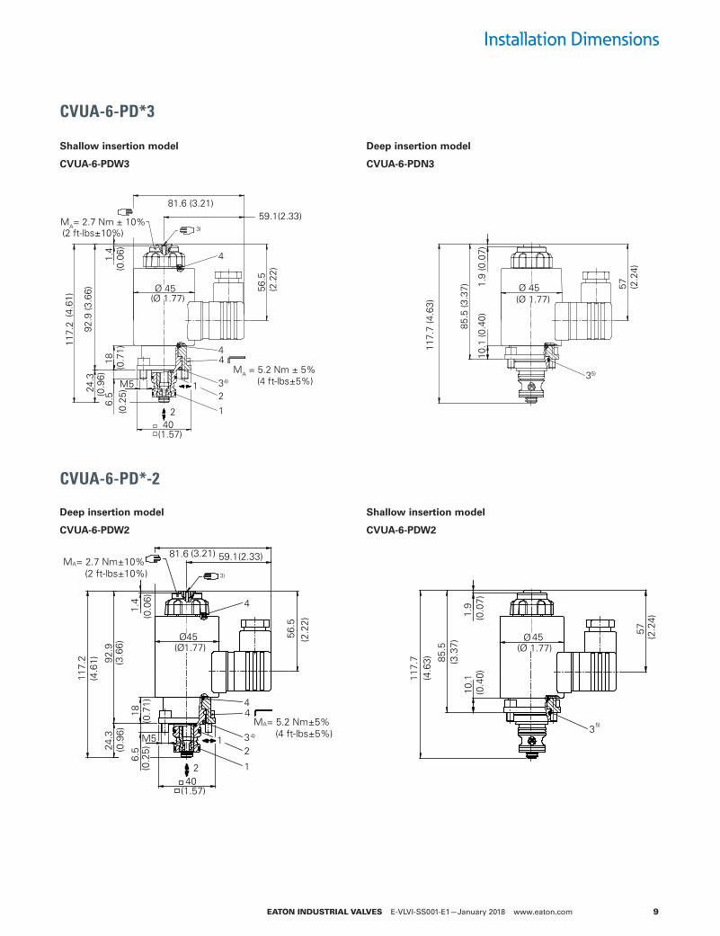
Installation Dimensions
CVUA-6-PD*3
CVUA-6-PD*-2
Shallow insertion model
CVUA-6-PDW3
Deep insertion model
CVUA-6-PDW2
Deep insertion model
CVUA-6-PDN3
Shallow insertion model
CVUA-6-PDW2
18
92.9
(3.6
6)24
.3
117.
2
6.5
10.1
85.5
117.
7(4
.63)
M5
56.5
(2.2
2)
57
1.91.4
59.1(2.33)81.6 (3.21)
1
2 1
234)
4
4
35)
40
4 MA= 5.2 Nm±5% (4 ft-lbs±5%)
Ø 45 Ø 45
MA= 2.7 Nm±10% (2 ft-lbs±10%) 3)
(0.9
6)
(0.0
6)
(4.6
1)
(Ø 1.77)
(1.57)
(0.2
5)(0
.71)
(2.2
4)(0.0
7)
(3.3
7)
(0.4
0)
(Ø 1.77)
18
92.9
(3.6
6)24
.3
117.
2
6.5
10.1
(0.4
0)
85.5
(3.3
7)
117.
7 (4
.63)
M5
56.5
(2.2
2)
57 (2.2
4)
1.9
(0.0
7)
1.4
59.1(2.33)81.6 (3.21)
1
2 1
234)
4
4
35)
40
4MA = 5.2 Nm ± 5% (4 ft-lbs±5%)
Ø 45
MA= 2.7 Nm ± 10%3)
(0.9
6)
(2 ft-lbs±10%)
(0.0
6)
(4.6
1) (Ø 1.77)
(1.57)
(0.2
5)(0
.71)
Ø 45 (Ø 1.77)
EATON INDUSTRIAL VALVES E-VLVI-SS001-E1—January 2018 www.eaton.com10
1
2
31
3
5
6
7
8
1
10
1
1
1
1
1
1
1
1
1
1
1
1
1
1
1
1
1
1
1
1
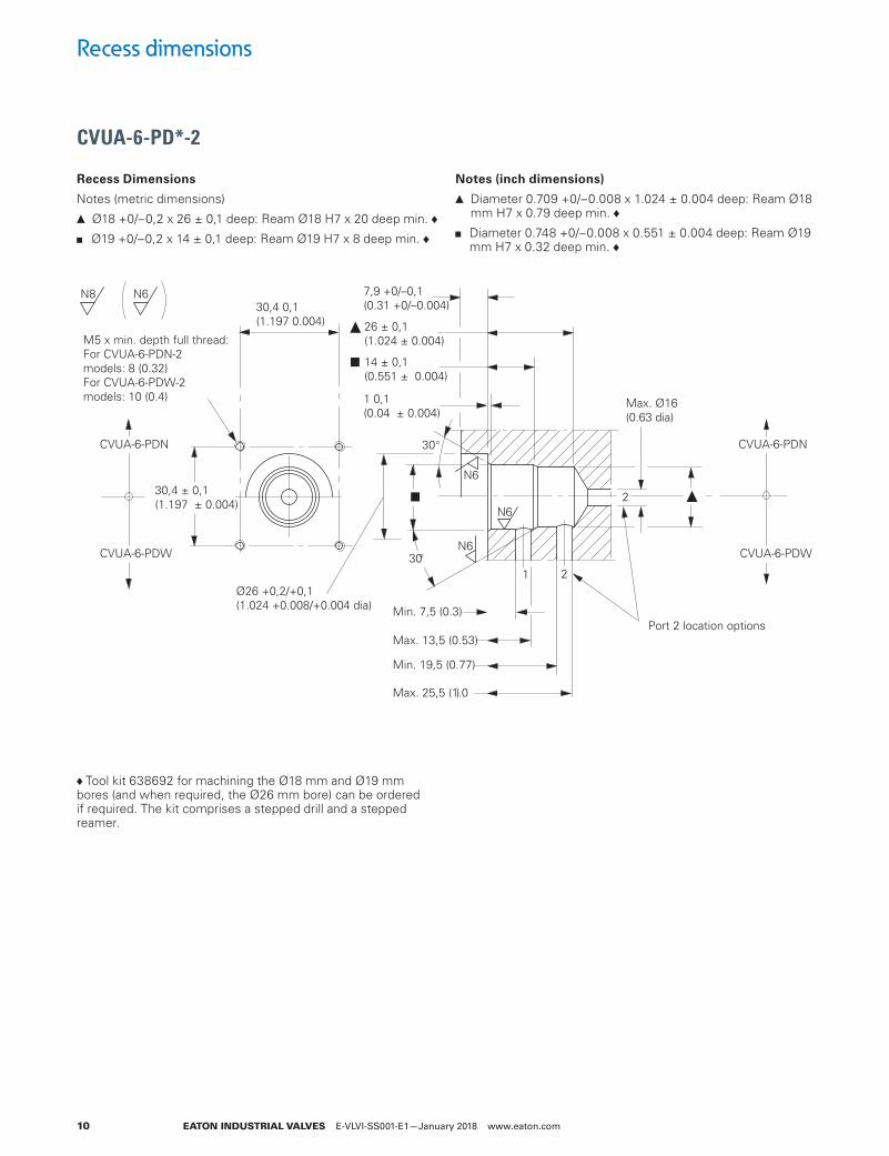
Recess dimensions
CVUA-6-PD*-2
Tool kit 638692 for machining the Ø18 mm and Ø19 mm bores (and when required, the Ø26 mm bore) can be ordered if required. The kit comprises a stepped drill and a stepped reamer.
Recess Dimensions
Notes (metric dimensions)
▲ Ø18 +0/–0,2 x 26 ± 0,1 deep: Ream Ø18 H7 x 20 deep min.
■ Ø19 +0/–0,2 x 14 ± 0,1 deep: Ream Ø19 H7 x 8 deep min.
Notes (inch dimensions)
▲ Diameter 0.709 +0/–0.008 x 1.024 ± 0.004 deep: Ream Ø18 mm H7 x 0.79 deep min.
■ Diameter 0.748 +0/–0.008 x 0.551 ± 0.004 deep: Ream Ø19 mm H7 x 0.32 deep min.
N6
CVUA-6-PDN
CVUA-6-PDW
CVUA-6-PDN
CVUA-6-PDW
30,4 0,1(1.197 0.004)
14 ± 0,1(0.551 ± 0.004)
26 ± 0,1(1.024 ± 0.004)
7,9 +0/–0,1(0.31 +0/–0.004)
1 0,1(0.04 ± 0.004)
Min. 7,5 (0.3)
Max. 13,5 (0.53)
Min. 19,5 (0.77)
Max. 25,5 (1.0)
Ø26 +0,2/+0,1(1.024 +0.008/+0.004 dia)
N6
N6
30
30
Max. Ø16(0.63 dia)
30,4 ± 0,1(1.197 ± 0.004)
1 2
2
Port 2 location options
N8 N6
M5 x min. depth full thread:For CVUA-6-PDN-2 models: 8 (0.32)For CVUA-6-PDW-2 models: 10 (0.4)
EATON INDUSTRIAL VALVES E-VLVI-SS001-E1—January 2018 www.eaton.com 11
1
2
3
4
5
6
7
8
1
10
1
1
1
1
1
1
1
1
1
1
1
1
1
1
1
1
1
1
1
1
Recess dimensions
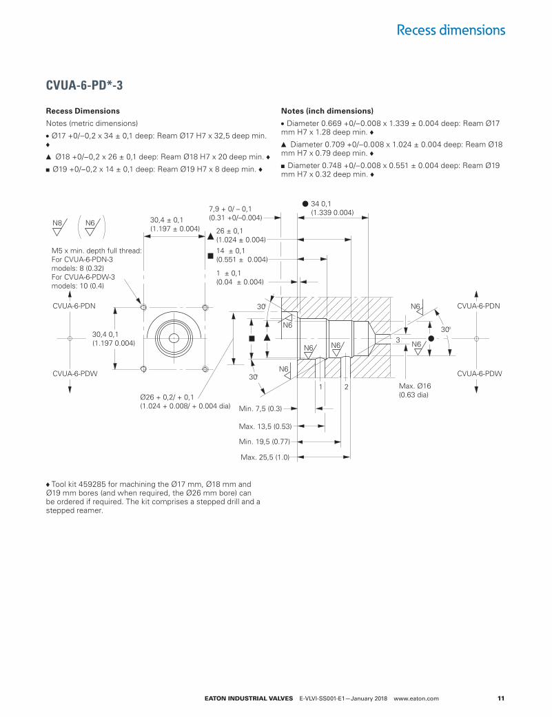
CVUA-6-PD*-3
N8 N6
N6
CVUA-6-PDN
CVUA-6-PDW
CVUA-6-PDN
CVUA-6-PDW
N6
34 0,1(1.339 0.004)7,9 + 0/ – 0,1
(0.31 +0/–0.004)30,4 ± 0,1(1.197 ± 0.004)
M5 x min. depth full thread:For CVUA-6-PDN-3 models: 8 (0.32)For CVUA-6-PDW-3 models: 10 (0.4)
26 ± 0,1(1.024 ± 0.004)14 ± 0,1(0.551 ± 0.004)
1 ± 0,1(0.04 ± 0.004)
Min. 7,5 (0.3)
Max. 13,5 (0.53)
Min. 19,5 (0.77)
Max. 25,5 (1.0)
Ø26 + 0,2/ + 0,1(1.024 + 0.008/ + 0.004 dia)
N6
N6
N6
N6 30
30
30
Max. Ø16(0.63 dia)
30,4 0,1(1.197 0.004)
1 2
3
Tool kit 459285 for machining the Ø17 mm, Ø18 mm and Ø19 mm bores (and when required, the Ø26 mm bore) can be ordered if required. The kit comprises a stepped drill and a stepped reamer.
Recess Dimensions
Notes (metric dimensions)
• Ø17 +0/–0,2 x 34 ± 0,1 deep: Ream Ø17 H7 x 32,5 deep min.
▲ Ø18 +0/–0,2 x 26 ± 0,1 deep: Ream Ø18 H7 x 20 deep min.
■ Ø19 +0/–0,2 x 14 ± 0,1 deep: Ream Ø19 H7 x 8 deep min.
Notes (inch dimensions)
• Diameter 0.669 +0/–0.008 x 1.339 ± 0.004 deep: Ream Ø17 mm H7 x 1.28 deep min.
▲ Diameter 0.709 +0/–0.008 x 1.024 ± 0.004 deep: Ream Ø18 mm H7 x 0.79 deep min.
■ Diameter 0.748 +0/–0.008 x 0.551 ± 0.004 deep: Ream Ø19 mm H7 x 0.32 deep min.

Follow us on social media to get the latest product and support information.Follow us on social media to get the latest product and support information.Eaton is a registered trademark.
All other trademarks are property of their respective owners.
© 2018 EatonAll Rights ReservedPrinted in USAPublication No. E-VLVI-SS001-E1 / 4416February 2018
EatonHydraulics Business USA14615 Lone Oak RoadEden Prairie, MN 55344USATel: 952-937-9800Fax: 952-294-7722www.eaton.com/hydraulics
EatonHydraulics Business EuropeRoute de la Longeraie 71110 MorgesSwitzerlandTel: +41 (0) 21 811 4600Fax: +41 (0) 21 811 4601
EatonHydraulics Group Asia PacificEaton Building4th Floor, No. 3 Lane 280 Linhong Rd.Changning DistrictShanghai 200335ChinaTel: (+86 21) 5200 0099Fax: (+86 21) 5200 0400