SOLD BY laptopia2005 DO NOT RESELL!! - ELHVB Manual...vii Preface This service and reference manual...
72
First Printing — August 1995 Copyright 1995 Copyright 1995 NEC Technologies, Inc. NEC Corporation 1414 Massachusetts Avenue 7-1 Shiba 5-Chome, Minato-Ku Boxborough, MA 01719 Tokyo 108-01, Japan All Rights Reserved All Rights Reserved PROPRIETARY NOTICE AND LIABILITY DISCLAIMER The information disclosed in this document, including all designs and related materials, is the valuable property of NEC Corporation (NEC) and/or its licensors. NEC and/or its licen- sors, as appropriate, reserve all patent, copyright and other proprietary rights to this docu- ment, including all design, manufacturing, reproduction, use, and sales rights thereto, except to the extent said rights are expressly granted to others. The NEC product(s) discussed in this document are warranted in accordance with the terms of the Warranty Statement accompanying each product. However, actual performance of each such product is dependent upon factors such as system configuration, customer data, and operator control. Since implementation by customers of each product may vary, the suitability of specific product configurations and applications must be determined by the customer and is not warranted by NEC. To allow for design and specification improvements, the information in this document is subject to change at any time, without notice. Reproduction of this document or portions thereof without prior written approval of NEC is prohibited. FastFacts, and NEC SVGA, are U.S. trademarks of NEC Technologies, Inc. All other product, brand, or trade names used in this publication are the trademarks or registered trademarks of their respective trademark owners. SOLD BY laptopia2005 DO NOT RESELL!! SOLD BY laptopia2005 DO NOT RESELL!!
Transcript of SOLD BY laptopia2005 DO NOT RESELL!! - ELHVB Manual...vii Preface This service and reference manual...

First Printing — August 1995
Copyright 1995 Copyright 1995NEC Technologies, Inc. NEC Corporation
1414 Massachusetts Avenue 7-1 Shiba 5-Chome, Minato-KuBoxborough, MA 01719 Tokyo 108-01, Japan
All Rights Reserved All Rights Reserved
PROPRIETARY NOTICE AND LIABILITY DISCLAIMER
The information disclosed in this document, including all designs and related materials, isthe valuable property of NEC Corporation (NEC) and/or its licensors. NEC and/or its licen-sors, as appropriate, reserve all patent, copyright and other proprietary rights to this docu-ment, including all design, manufacturing, reproduction, use, and sales rights thereto, exceptto the extent said rights are expressly granted to others.
The NEC product(s) discussed in this document are warranted in accordance with the termsof the Warranty Statement accompanying each product. However, actual performance ofeach such product is dependent upon factors such as system configuration, customer data,and operator control. Since implementation by customers of each product may vary, thesuitability of specific product configurations and applications must be determined by thecustomer and is not warranted by NEC.
To allow for design and specification improvements, the information in this document issubject to change at any time, without notice. Reproduction of this document or portionsthereof without prior written approval of NEC is prohibited.
FastFacts, and NEC SVGA, are U.S. trademarks of NEC Technologies, Inc.
All other product, brand, or trade names used in this publication are the trademarks or registered trademarks of their respective trademark owners.
SOLD BY laptopia2005 DO NOT RESELL!!
SOLD BY laptopia2005 DO NOT RESELL!!

vii
Preface
This service and reference manual contains the technical information necessary to set up,and maintain the NEC Versa™ 4000 Series notebook systems. It also provides hardwareand interface information for users who need an overview of the computer system design.The manual is written for NEC-trained customer engineers, system analysts, service centerpersonnel, and dealers.
Please refer to the training module provided on CD-ROM for system disassembly/assemblyprocedures.
The manual is organized as follows:
Section 1 Technical Information, provides an overview of the hardware and interfacecomponents. System specifications are listed including computer dimensions, weight, envi-ronment, safety compliance, power consumption, and system memory specifications.
Section 2 Setup and Operation, takes the user from unpacking to setup and operation.The section includes a description of operating controls, setting parameters and accessingthe NEC bulletin board system (BBS).
Section 3 Illustrated Parts Breakdown (IPB), provides an exploded-view diagram ofthe NEC Versa 4000 series system and part numbers.
Appendix A Connector Locations and Pin Assignments, provides a list of the mainboard internal connector pin assignments and a list of external pin assignments.
An Index is included for convenience.
SOLD BY laptopia2005 DO NOT RESELL!!
SOLD BY laptopia2005 DO NOT RESELL!!

iii
Contents
Preface......................................................................................................................... vii
Abbreviations............................................................................................................... ix
Section 1 Technical Information
Hardware Overview..................................................................................................... 1-2
Liquid Crystal Display (LCD)................................................................................ 1-2
CPU Board ........................................................................................................... 1-3
I/O Board ............................................................................................................. 1-3
Sound Board......................................................................................................... 1-3
Infrared (IR) Front Assembly, Rear Assembly ....................................................... 1-4
Battery Pack ......................................................................................................... 1-4
CMOS Battery...................................................................................................... 1-4
Bridge Battery ...................................................................................................... 1-4
PCMCIA Slots...................................................................................................... 1-4
Diskette Drive and the NEC VersaBay II .............................................................. 1-5
Keyboard .............................................................................................................. 1-5
NEC VersaGlide ................................................................................................... 1-5
System Memory........................................................................................................... 1-5
Memory Map........................................................................................................ 1-6
System Video............................................................................................................... 1-7
Parallel Interface .......................................................................................................... 1-11
Serial Interface............................................................................................................. 1-12
NEC Versa 4000 Series Chip Set ................................................................................. 1-12
Intel Pentium P54LM............................................................................................ 1-12
Cache Controller, Address Logic, Data Controller................................................. 1-13
System Logic, IDE Interface, Peripheral Controller............................................... 1-13
Flash ROM ........................................................................................................... 1-13
ROM BIOS.................................................................................................... 1-14
VGA Controller .................................................................................................... 1-14
Video Controller Architecture ........................................................................ 1-15
Diskette Controller, Serial Interface, Parallel Interface.......................................... 1-15
Keyboard Controller ............................................................................................. 1-15
PCMCIA Controller.............................................................................................. 1-15
Interrupt Controllers ............................................................................................. 1-16
SOLD BY laptopia2005 DO NOT RESELL!!
SOLD BY laptopia2005 DO NOT RESELL!!
iv Contents
Power Management Overview ..................................................................................... 1-17
System Power Management .................................................................................. 1-17
Local Power Management..................................................................................... 1-18
Plug and Play............................................................................................................... 1-18
Specifications............................................................................................................... 1-19
Section 2 Setup and Operation
Unpacking the System.................................................................................................. 2-1
Hardware Setup........................................................................................................... 2-1
Cable Connections ................................................................................................ 2-2
Operating Controls ...................................................................................................... 2-3
Status Bar............................................................................................................. 2-4
Status Icons ................................................................................................... 2-5
Battery Status ................................................................................................ 2-5
Function Keys (Fn Keys)....................................................................................... 2-6
Smart Power Switch ............................................................................................. 2-6
Dip Switch............................................................................................................ 2-7
Power-on Self-Test (Post)............................................................................................ 2-8
POST Errors......................................................................................................... 2-9
Setup Utility................................................................................................................ 2-10
Accessing Setup.................................................................................................... 2-10
With an Error at POST .................................................................................. 2-10
With No Errors at POST................................................................................ 2-10
Setup Screen......................................................................................................... 2-11
Setup Keys..................................................................................................... 2-11
Changing/Setting Parameter Settings............................................................................ 2-11
Parameter Options ....................................................................................................... 2-13
Parameter Descriptions ......................................................................................... 2-14
Time/Date...................................................................................................... 2-14
Drives ............................................................................................................ 2-14
Peripherals ..................................................................................................... 2-14
Security ......................................................................................................... 2-15
Power Savings ............................................................................................... 2-15
Security Options .......................................................................................................... 2-16
System Password .................................................................................................. 2-16
Using the System Password............................................................................ 2-16
Keyboard Lock Hotkey......................................................................................... 2-17
SOLD BY laptopia2005 DO NOT RESELL!!
SOLD BY laptopia2005 DO NOT RESELL!!
Contents v
BIOS Update Utility (BUU)......................................................................................... 2-17
Precautions........................................................................................................... 2-17
Downloading the Update Utility............................................................................ 2-17
Using the Update Utility........................................................................................ 2-18
Menu Functions .................................................................................................... 2-20
Power Sources............................................................................................................. 2-23
AC Adapter .......................................................................................................... 2-23
Battery Power....................................................................................................... 2-24
Recharging the Battery Pack .......................................................................... 2-24
Replacing the Battery Pack .......................................................................................... 2-24
Saving Battery Power ........................................................................................... 2-26
Automatic Power-Saving Features ............................................................................... 2-27
Section 3 Illustrated Parts Br eakdown
Appendix A Connector Locations and Pin Assignments
List of Figures
1-1 NEC Versa 4000 Series System Features ....................................................... 1-1
1-2 NEC Versa 4000 Series (Rear View).............................................................. 1-2
2-1 Power and I/O Connector Locations .............................................................. 2-2
2-2 Keyboard Panel Controls................................................................................ 2-3
2-3 Right Side Panel Controls .............................................................................. 2-3
2-4 Status Bar Location ....................................................................................... 2-4
2-5 Status Bar Icons............................................................................................. 2-5
2-6 Dip Switch Location ...................................................................................... 2-7
2-7 Dip Switch Settings........................................................................................ 2-7
2-8 Connecting the AC Adapter ........................................................................... 2-23
2-9 Battery Cover Latch Location ........................................................................ 2-25
2-10 Battery Pack Replacement.............................................................................. 2-25
2-11 Battery Bay Cover Replacement..................................................................... 2-26
3-1 NEC Versa 4000 Series Illustrated Parts Breakdown...................................... 3-3
A-1 System Board Connector Locations ............................................................... A-1
SOLD BY laptopia2005 DO NOT RESELL!!
SOLD BY laptopia2005 DO NOT RESELL!!

vi Contents
List of Tables
1-1 NEC Versa 4000 Series System Memory Map ............................................... 1-6
1-2 CRT Display Mode (CRT only)...................................................................... 1-7
1-3 LCD Display Modes (640 x 480 TFT, Simultaneous CRT)............................. 1-9
1-4 LCD Display Modes (640 x 480 DSTN, Simultaneous CRT) ......................... 1-10
1-5 NEC Versa 4000 Series Chip Types and Technologies ................................... 1-12
1-6 NEC Versa 4000 Series Interrupt Level Assignments ..................................... 1-16
1-7 Maximum Performance Default Settings......................................................... 1-18
1-8 Specifications................................................................................................. 1-19
2-1 I/O Connector Descriptions............................................................................ 2-2
2-2 Control and Switch Functions ........................................................................ 2-4
2-3 FnKey Operations .......................................................................................... 2-6
2-4 POST Error Messages.................................................................................... 2-9
2-5 Setup Key Functions ...................................................................................... 2-11
2-6 System Parameter Settings ............................................................................. 2-13
2-7 Automatic Power-Saving Features ................................................................. 2-27
3-1 NEC Versa 4000 Series Field-Replaceable Parts............................................. 3-1
3-2 Option and Documentation Part Numbers ...................................................... 3-4
A-1 CPU Board Connectors.................................................................................. A-1
A-2 Keyboard/Mouse Connector Pin Assignments ................................................ A-1
A-3 Serial Port Connector Pin Assignments .......................................................... A-2
A-4 CRT Connector Pin Assignments ................................................................... A-2
A-5 Parallel Printer Pin Assignments ..................................................................... A-3
A-6 Expansion Connector Pin Assignments........................................................... A-4
A-7 Power Connector ........................................................................................... A-8
A-8 Hard Disk Drive Connector............................................................................ A-9
A-9 Diskette Drive Connector............................................................................... A-10
SOLD BY laptopia2005 DO NOT RESELL!!
SOLD BY laptopia2005 DO NOT RESELL!!
Section 1
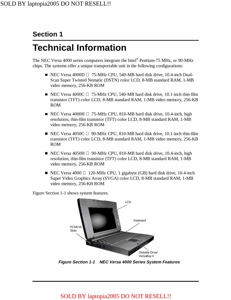
Technical InformationThe NEC Versa 4000 series computers integrate the Intel® Pentium-75 MHz, or 90-MHzchips. The systems offer a unique transportable unit in the following configurations:
� NEC Versa 4000D 75-MHz CPU, 540-MB hard disk drive, 10.4-inch Dual-Scan Super Twisted Nematic (DSTN) color LCD, 8-MB standard RAM, 1-MBvideo memory, 256-KB ROM
� NEC Versa 4000C 75-MHz CPU, 540-MB hard disk drive, 10.1-inch thin-filmtransistor (TFT) color LCD, 8-MB standard RAM, 1-MB video memory, 256-KBROM
� NEC Versa 4000H 75-MHz CPU, 810-MB hard disk drive, 10.4-inch, highresolution, thin-film transistor (TFT) color LCD, 8-MB standard RAM, 1-MBvideo memory, 256-KB ROM
� NEC Versa 4050C 90-MHz CPU, 810-MB hard disk drive, 10.1-inch thin-filmtransistor (TFT) color LCD, 8-MB standard RAM, 1-MB video memory, 256-KBROM
� NEC Versa 4050H 90-MHz CPU, 810-MB hard disk drive, 10.4-inch, highresolution, thin-film transistor (TFT) color LCD, 8-MB standard RAM, 1-MBvideo memory, 256-KB ROM
� NEC Versa 4000 120-MHz CPU, 1 gigabyte (GB) hard disk drive, 10.4-inchSuper Video Graphics Array (SVGA) color LCD, 8-MB standard RAM, 1-MBvideo memory, 256-KB ROM
Figure Section 1-1 shows system features.
Figure Section 1-1 NEC Versa 4000 Series System Features
LCD
Keyboard
PCMCIASlots
Diskette Drive/VersaBay II
SOLD BY laptopia2005 DO NOT RESELL!!
SOLD BY laptopia2005 DO NOT RESELL!!

1-2 Technical Information
HARDWARE OVERVIEW
The base unit includes a color LCD panel, a 2 1/2-inch 540-MB, or 810-MB hard diskdrive, a 3 1/2-inch, 1.44-MB diskette drive, a battery pack, and a PS/2 compatible 83-keykeyboard. A 79-key keyboard is used for U.K. and Germany. The NEC VersaGlide touch-pad is positioned at the front of the keyboard, and takes the place of a mouse.
Multimedia features include built-in stereo speakers and a built-in microphone. Multimediaports include line-in, line-out, headphone and external microphone.
One memory card slot is available for the addition of a 4-, 8- , 16-, or 32-MB capacitymemory card. Two Personal Computer Memory Card International Association (PCMCIA)card slots, supported by the Cirrus Logic PD6722 PCMCIA controller, allow for the addi-tion of either two PCMCIA Type 1/Type II cards or one PCMCIA Type III card.
Figure Section 1-2 shows the standard I/O interface ports on the system's rear panel. Theseinclude one 6-pin shared PS/2-style keyboard/mouse port, one 9-pin (RS-232C) serial port,one 25-pin enhanced printer (parallel) port, one 15-pin Super VGA CRT port, one Infrared(IR) port, one expansion connector, and one 4-pin power connector port.
Figure Section 1-2 NEC Versa 4000 Series (Rear View)
Liquid Crystal Display (LCD)
The system integrates a built-in LCD. The LCD supports VESA Local (VL) bus video. TheLCD operates with the Chips & Technologies 65545B1-5 VGA controller. The controllersupports Super VGA. For more information on the 65545B1-5 or 65545B2-H VGA con-troller, read the description provided in the NEC Versa 4000 Series Chip Set subsection.
Mouse/Keyboard Port
Serial Port
EnhancedParallel Port
CRT Port IR Port
Expansion Port
Power Port
SOLD BY laptopia2005 DO NOT RESELL!!
SOLD BY laptopia2005 DO NOT RESELL!!

Technical Information 1-3
The NEC Versa 4000 series system features the following types of LCDs.
� TFT — 10.1-inch thin-film transistor backlit color LCD, 0.32 mm dot pitch, 18-bit digital interface, 640 x 480 resolution, 256,000 colors.
� DSTN — 10.4-inch dual-scan super twisted nematic color LCD, 0.33 mm dotpitch, 16-bit digital interface, 600 x 480 resolution, 256,000 colors, (64K colorson an external CRT).
� High Resolution TFT — 10.4-inch thin film transistor color LCD, 0.26 mm dotpitch, 18-bit digital interface, 800 x 600 resolution, 256,000 colors, (64K colorson an external CRT).
In addition, the CRT port on the system's rear panel allows the user to connect an optionalmonochrome or color external display to the system. The computer supports the LCD andexternal display simultaneously.
Power-saving features for controlling the LCD's backlighting include the ROM-based hotkey Fn F5, and Auto Setup power management settings. See Section 2, Setup and Opera-tion, for information on using these settings. In addition, the automatic LCD status sensefeature conserves the backlight. When the LCD is closed the backlight shuts off, savingbattery power.
CPU Board
The CPU board (75 Mhz, 90 MHz or 120 MHz) CPU board is an L-shaped board situatednext to the audio ports. In addition to the CPU, this board houses the bridge battery andspeaker. It controls important functions including power management, direct drive bus in-terface and memory management.
I/O Board
The I/O board (G8TUP) contains peripheral subsystems including serial, parallel and videoports. It is located underneath the sound board.
I/O board specifications are listed in Table Section 1-8 at the end of this section.
Sound Board
The sound board (G8UNA) provides the NEC Versa 4000 series system with its audio ca-pabilities via line-in/line-out jacks, and headphone/microphone jacks. It is situated on top ofthe I/O board.
SOLD BY laptopia2005 DO NOT RESELL!!
SOLD BY laptopia2005 DO NOT RESELL!!

1-4 Technical Information
Infrared (IR) Front Assembly, Rear Assembly
Two IR assemblies are connected to the I/O board via connectors P10 and P11 respectively.One is located on the front of the NEC Versa, the second one is located on the rear of theNEC Versa.
Each IR assembly consists of a small board with infrared LEDs. The board allows the NECVersa 4000 series computer to communicate with other infrared-ready computers. For ex-ample, the infrared ports allow the user to transfer files between the NEC Versa and an IR-equipped desktop, or print to an IR-equipped printer without using cables.
The NEC Versa 4000 series system ships with the rear IR assembly disabled and the frontIR assembly disabled. When the NEC Versa 4000 is docked to the optional NEC VersaDocking Station 4000, the rear IR assembly is automatically disabled, and the front enabled.
Battery Pack
The system uses a rechargeable lithium-ion (Li-ION) battery as its transient power source.The battery pack installs in the compartment next to the standard diskette drive on the bot-tom of the Versa 4000. The battery uses 10.8 volts with a 2500 mAh capacity.
The battery pack powers the NEC Versa 4000 for approximately 5 hours with Power Man-agement or 2.5 hours without Power management. In addition, the battery pack lets theuser know how much battery power is available via the LEDs on the front of the system, orthe battery gas gauge in the power panel.
When battery power is getting low, connect the AC adapter to a wall outlet and rechargethe battery. It takes 2.5 hours to recharge the battery pack when the system is powered off,(Quick Charge). It takes 2.5 hours to recharge the battery while the system is powered on,(Normal Charge).
CMOS Battery
The lithium battery (3.0 Volts, 280 mAh capacity) is attached to connector P12 on the CPUboard. It provides battery backup and prevents data loss in the system’s complementarymetal oxide semiconductor (CMOS) RAM. This memory area contains information on thesystem’s configuration like date, time, drives, and memory. The CMOS battery lasts ap-proximately two years.
Bridge Battery
The bridge battery saves the memory contents and system status for up to 5 minutes whilein Suspend mode. It is connected to the CPU board via P8. The AC adapter maintains volt-age in the bridge battery when the system is powered on or off. The bridge battery provides6 Volts, 60 mAH.
SOLD BY laptopia2005 DO NOT RESELL!!
SOLD BY laptopia2005 DO NOT RESELL!!

Technical Information 1-5
PCMCIA Slots
The Versa 4000 provides a 5 volt, or 3.3 volt interface for either two Type I/Type IIPCMCIA cards, or one Type III PCMCIA card.
Diskette Drive and the NEC VersaBay II
A standard 1.44-MB diskette drive comes installed in the VersaBay II slot on the front ofthe system. The VersaBay II expansion slot allows the user to replace the standard diskettedrive with a number of different NEC options including a CD-ROM reader, a second bat-tery pack, or an additional hard disk drive using the release latches on the bottom of theunit.
Keyboard
The built-in, 83-key keyboard (U.S) or 79-key keyboard (UK and Germany) uses the stan-dard QWERTY format. The keyboard provides 12 function keys and 8 cursor control keys,with an Fn key for ROM-based key functions. The numeric keypad is embedded in the stan-dard key layout.
NEC VersaGlide
The NEC VersaGlide is a built-in mechanism that functions as the system’s mouse. It con-trols the on-screen pointer (cursor). To use the VersaGlide, glide your finger across theNEC VersaGlide pad, and the cursor follows. The buttons on either side of the NEC Ver-saGlide allow the user to select or deselect menu items. Tap and double-tap are supportedon the VersaGlide pad.
The NEC VersaGlide is the system's default pointing device unless a PS/2 mouse is in-stalled. If an external mouse is installed, then the NEC VersaGlide is deactivated. A serialmouse is not supported.
SYSTEM MEMORY
The system board provides 8-MB of standard random access memory (RAM).The NECVersa 4000 operates with 4 banks. Banks 0 to 1 are used for the standard 8-MB (with in-terleaved access support). Banks 2 to 4 are used for memory expansion (without interleavedaccess support).
Optional memory cards with a value of 4-, 8-, 16-, or 32-MB can be added to increase sys-tem memory up to a maximum of 40-MB. In addition, 256 KB of read-only memory(ROM), 1 x 28F020, enables the system BIOS to be flashed.
Cache RAM is available with L1 write-back access support providing 8 KB for code, 8 KBfor data. L2 write-through access support providing 256 KB.
SOLD BY laptopia2005 DO NOT RESELL!!
SOLD BY laptopia2005 DO NOT RESELL!!
1-6 Technical Information
Memory Map
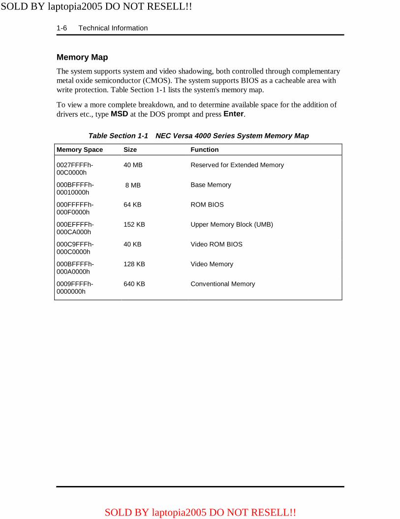
The system supports system and video shadowing, both controlled through complementarymetal oxide semiconductor (CMOS). The system supports BIOS as a cacheable area withwrite protection. Table Section 1-1 lists the system's memory map.
To view a more complete breakdown, and to determine available space for the addition ofdrivers etc., type MSD at the DOS prompt and press Enter .
Table Section 1-1 NEC Versa 4000 Series System Memory Map
Memory Space Size Function
0027FFFFh-00C0000h
40 MB Reserved for Extended Memory
000BFFFFh-00010000h
8 MB Base Memory
000FFFFFh-000F0000h
64 KB ROM BIOS
000EFFFFh-000CA000h
152 KB Upper Memory Block (UMB)
000C9FFFh-000C0000h
40 KB Video ROM BIOS
000BFFFFh-000A0000h
128 KB Video Memory
0009FFFFh-0000000h
640 KB Conventional Memory
SOLD BY laptopia2005 DO NOT RESELL!!
SOLD BY laptopia2005 DO NOT RESELL!!

Technical Information 1-7
SYSTEM VIDEO
The system's LCD operates using the Chips and Technologies 65545B1-5 or 65545B2-HVGA Controller. Video signals travel from the controller through the system's 15-pin D-SUB connector using 5 volts.
System video integrates a 32-bit VL-bus interface using local bus video. The system shipswith 1 MB Video RAM (VRAM). It also supports video modes up to 1024 x 768 with 256colors in CRT mode.
Table Section 1-2 lists CRT display modes..
NOTE: Interlaced video modes are representedwith the letter I in the table below.
Table Section 1-2 CRT Display Mode (CRT only)
Mode(Hex)
DisplayMode
Colors
TextDisplay
Resolution
Font
RefreshRate
0, 1 Text 16 40x25 320x200 8x8 70
0*, 1* Text 16 40x25 320x200 8x14 70
0**, 1** Text 16 40x25 360x400 9x16 70
2, 3 Text 16 80x25 640x200 8x8 70
2*, 3* Text 16 80x25 640x350 8x14 70
2**, 3** Text 16 80x25 720x400 9x16 70
4,5* Graphics 4 40x25 320x200 8x8 70
6 Graphics 2 80x25 640x200 8x8 70
7* Text Mono 80x25 720x350 9x14 70
7** Text Mono 80x25 720x400 9x16 70
D Planar 16 40x25 320x200 8x8 70
E Planar 16 80x25 640x200 8x8 70
F Planar Mono 80x25 640x350 8x14 70
10 Planar 16 80x25 640x350 8x14 70
11 Planar 2 80x30 6400x480 8x16 60
12 Planar 16 80x30 640x480 8x16 60
12*** Planar 16 80x30 640x480 8x16 74
13 PackedPixel
256 40x25 320x200 8x8 70
20 4-bit linear 16 80x30 640x480 8x16 60
SOLD BY laptopia2005 DO NOT RESELL!!
SOLD BY laptopia2005 DO NOT RESELL!!

1-8 Technical Information
Table Section 1-2 CRT Display Mode (CRT only)
Mode(Hex)
DisplayMode
Colors
TextDisplay
Resolution
Font
RefreshRate
22 4-bit linear 16 100x37 800x600 8x16 60
24 4-bit linear 16 128x48 1024x768 8x16 60
24I 4-bit linear 16 128x48 1024x768 8x16 43
30 8-bit linear 256 80x30 640x480 8x16 60
30*** 8-bit linear 256 80x30 640x480 8x16 74
32 8-bit linear 256 100x37 800x600 8x16 60
32*** 8-bit linear 256 100x37 800x600 8x16 74
34 8-bit linear 256 128x48 1024x768 8x16 60
34I 8-bit linear 256 128x48 1024x768 8x16 43
40 15-bitlinear
32K 80x30 640x480 8x16 60
41 16-bitlinear
64K 80x30 640x480 8x16 60
50 24-bitlinear
16 80x30 640x480 8x16 55
60 Text 16 132x25 1056x400 8x16 68
61 Text 16 132x50 1056x400 8x16 68
6A, 70 Planar 16 100x37 800x600 8x16 60
6A***70***
Planar 16 100x37 800x600 8x16 74
72, 75 Planar 16 128x48 1024x768 8x16 60
72I, 75I Planar 16 128x48 1024x768 8x16 43
78 PackedPixel
256 80x25 640x400 8x16 70
79 PackedPixel
256 80x30 640x480 8x16 60
79*** PackedPixel
256 80x30 640x480 8x16 74
7C PackedPixel
256 100x37 800x600 8x16 60
7C*** PackedPixel
256 100x37 800x600 8x16 74
SOLD BY laptopia2005 DO NOT RESELL!!
SOLD BY laptopia2005 DO NOT RESELL!!

Technical Information 1-9
Table Section 1-2 CRT Display Mode (CRT only)
Mode(Hex)
DisplayMode
Colors
TextDisplay
Resolution
Font
RefreshRate
7E1 PackedPixel
256 128x48 1024x768 8x16 43
7E1 PackedPixel
256 128x48 1024x768 8x16 60
*EGA Extension**VGA Extension***High Refresh Modes
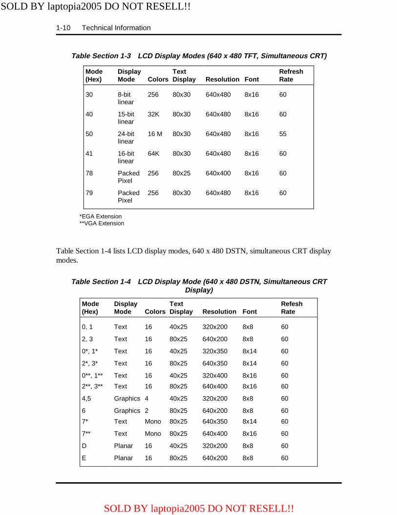
Table Section 1-3 lists 640 x 480, TFT simultaneous LCD/CRT display modes.
Table Section 1-3 LCD Display Modes (640 x 480 TFT, Simultaneous CRT)
Mode(Hex)
DisplayMode
Colors
TextDisplay
Resolution
Font
RefreshRate
0,1 Text 16 40x25 320x200 8x8 60
2,3 Text 16 80x25 640x200 8x8 60
0*, 1* Text 16 40x25 320x350 8x14 60
2*, 3* Text 16 80x25 640x350 8x14 60
0**, 1** Text 16 40x25 320x400 8x16 60
2**, 3** Text 16 80x25 640x400 8x16 60
4, 5 Graphics 4 40x25 320x200 8x8 60
6 Graphics 2 80x25 640x200 8x8 60
7* Text Mono 80x25 640x350 8x14 60
7** Text Mono 80x25 640x400 8x16 60
D Planar 16 40x25 320x200 8x8 60
E Planar 16 80x25 640x200 8x8 60
F Planar Mono 80x25 640x350 8x14 60
10 Planar 16 80x25 640x350 8x14 60
11 Planar 2 80x30 640x480 8x16 60
12 Planar 16 80x30 640x480 8x16 60
13 PackedPixel
256 40x25 320x200 8x8 60
20 4-bitlinear
16 80x30 640x480 8x16 60
SOLD BY laptopia2005 DO NOT RESELL!!
SOLD BY laptopia2005 DO NOT RESELL!!
1-10 Technical Information
Table Section 1-3 LCD Display Modes (640 x 480 TFT, Simultaneous CRT)
Mode(Hex)
DisplayMode
Colors
TextDisplay
Resolution
Font
RefreshRate
30 8-bitlinear
256 80x30 640x480 8x16 60
40 15-bitlinear
32K 80x30 640x480 8x16 60
50 24-bitlinear
16 M 80x30 640x480 8x16 55
41 16-bitlinear
64K 80x30 640x480 8x16 60
78 PackedPixel
256 80x25 640x400 8x16 60
79 PackedPixel
256 80x30 640x480 8x16 60
*EGA Extension**VGA Extension
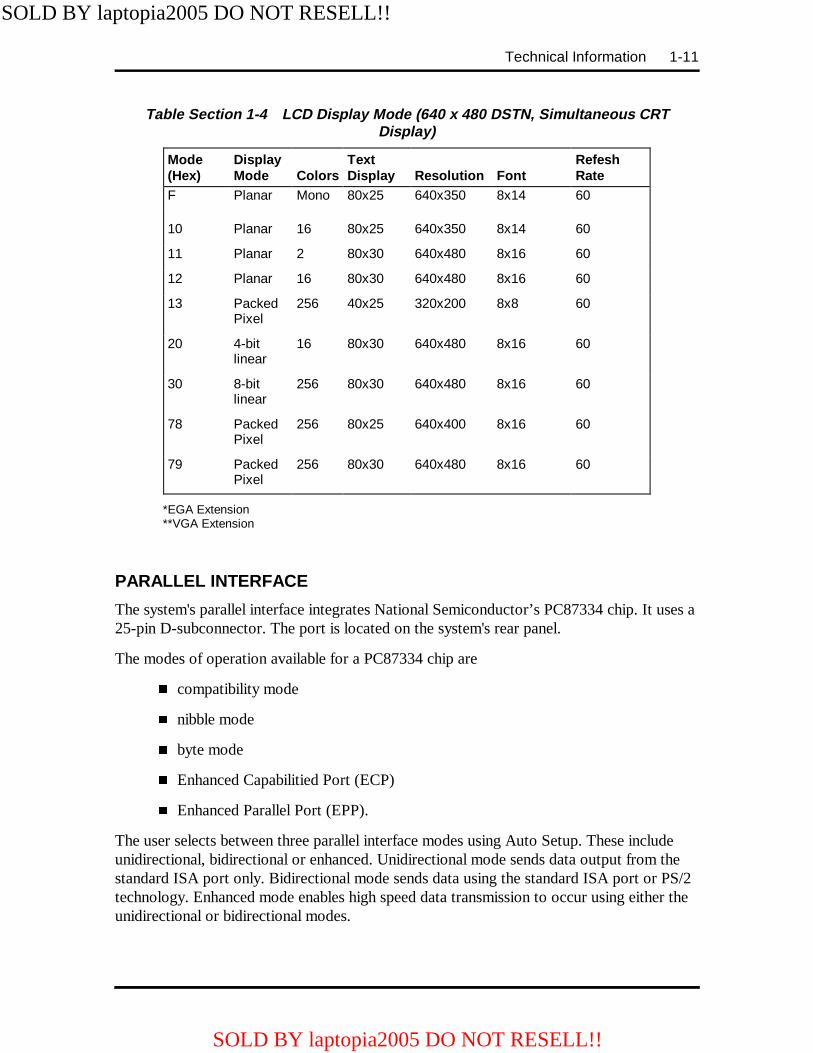
Table Section 1-4 lists LCD display modes, 640 x 480 DSTN, simultaneous CRT displaymodes.
Table Section 1-4 LCD Display Mode (640 x 480 DSTN, Simultaneous CRTDisplay)
Mode(Hex)
DisplayMode
Colors
TextDisplay
Resolution
Font
RefeshRate
0, 1 Text 16 40x25 320x200 8x8 60
2, 3 Text 16 80x25 640x200 8x8 60
0*, 1* Text 16 40x25 320x350 8x14 60
2*, 3* Text 16 80x25 640x350 8x14 60
0**, 1** Text 16 40x25 320x400 8x16 60
2**, 3** Text 16 80x25 640x400 8x16 60
4,5 Graphics 4 40x25 320x200 8x8 60
6 Graphics 2 80x25 640x200 8x8 60
7* Text Mono 80x25 640x350 8x14 60
7** Text Mono 80x25 640x400 8x16 60
D Planar 16 40x25 320x200 8x8 60
E Planar 16 80x25 640x200 8x8 60
SOLD BY laptopia2005 DO NOT RESELL!!
SOLD BY laptopia2005 DO NOT RESELL!!
Technical Information 1-11
Table Section 1-4 LCD Display Mode (640 x 480 DSTN, Simultaneous CRTDisplay)
Mode(Hex)
DisplayMode
Colors
TextDisplay
Resolution
Font
RefeshRate
F Planar Mono 80x25 640x350 8x14 60
10 Planar 16 80x25 640x350 8x14 60
11 Planar 2 80x30 640x480 8x16 60
12 Planar 16 80x30 640x480 8x16 60
13 PackedPixel
256 40x25 320x200 8x8 60
20 4-bitlinear
16 80x30 640x480 8x16 60
30 8-bitlinear
256 80x30 640x480 8x16 60
78 PackedPixel
256 80x25 640x400 8x16 60
79 PackedPixel
256 80x30 640x480 8x16 60
*EGA Extension**VGA Extension
PARALLEL INTERFACE
The system's parallel interface integrates National Semiconductor’s PC87334 chip. It uses a25-pin D-subconnector. The port is located on the system's rear panel.
The modes of operation available for a PC87334 chip are
� compatibility mode
� nibble mode
� byte mode
� Enhanced Capabilitied Port (ECP)
� Enhanced Parallel Port (EPP).
The user selects between three parallel interface modes using Auto Setup. These includeunidirectional, bidirectional or enhanced. Unidirectional mode sends data output from thestandard ISA port only. Bidirectional mode sends data using the standard ISA port or PS/2technology. Enhanced mode enables high speed data transmission to occur using either theunidirectional or bidirectional modes.
SOLD BY laptopia2005 DO NOT RESELL!!
SOLD BY laptopia2005 DO NOT RESELL!!
1-12 Technical Information
The parallel port address is 378h and the interrupt level is IRQ07. Pin locations for the par-allel interface are listed in Appendix A.
SERIAL INTERFACE
The RS-232C serial port is a 9-pin connector on the system’s rear panel. The serial portconsists of a 16550 compatible serial port controller with a programmable baud rate up to115,200 bps. The serial port connects an RS-232C device or an external modem. The serialport address is 3F8h and the interrupt level is IRQ04.
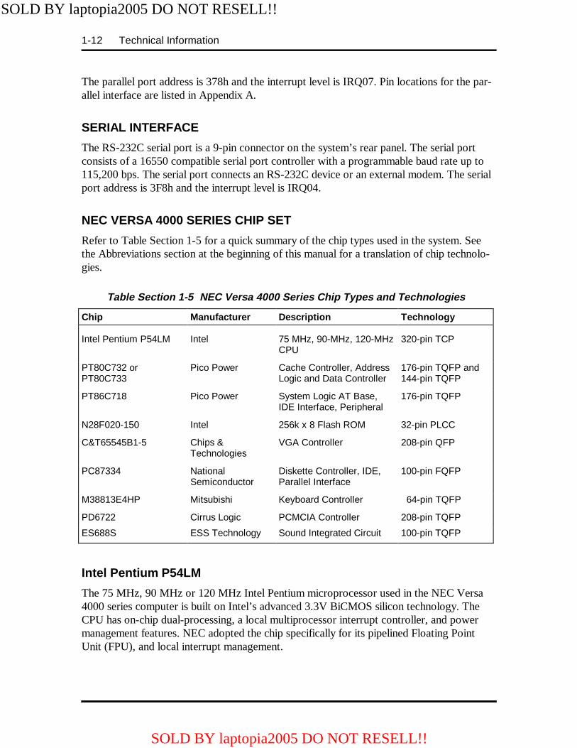
NEC VERSA 4000 SERIES CHIP SET
Refer to Table Section 1-5 for a quick summary of the chip types used in the system. Seethe Abbreviations section at the beginning of this manual for a translation of chip technolo-gies.
Table Section 1-5 NEC Versa 4000 Series Chip Types and Tec hnologies
Chip Manufacturer Description Technology
Intel Pentium P54LM Intel 75 MHz, 90-MHz, 120-MHzCPU
320-pin TCP
PT80C732 orPT80C733
Pico Power Cache Controller, AddressLogic and Data Controller
176-pin TQFP and144-pin TQFP
PT86C718 Pico Power System Logic AT Base,IDE Interface, Peripheral
176-pin TQFP
N28F020-150 Intel 256k x 8 Flash ROM 32-pin PLCC
C&T65545B1-5 Chips &Technologies
VGA Controller 208-pin QFP
PC87334 NationalSemiconductor
Diskette Controller, IDE,Parallel Interface
100-pin FQFP
M38813E4HP Mitsubishi Keyboard Controller 64-pin TQFP
PD6722 Cirrus Logic PCMCIA Controller 208-pin TQFP
ES688S ESS Technology Sound Integrated Circuit 100-pin TQFP
Intel Pentium P54LM
The 75 MHz, 90 MHz or 120 MHz Intel Pentium microprocessor used in the NEC Versa4000 series computer is built on Intel’s advanced 3.3V BiCMOS silicon technology. TheCPU has on-chip dual-processing, a local multiprocessor interrupt controller, and powermanagement features. NEC adopted the chip specifically for its pipelined Floating PointUnit (FPU), and local interrupt management.
SOLD BY laptopia2005 DO NOT RESELL!!
SOLD BY laptopia2005 DO NOT RESELL!!

Technical Information 1-13
Cache Controller, Address Logic, Data Controller
The Golden Gate PT80C732 and PT80C733 Pico Power controller provides a dual-chipstructure that connect the Pentium processor to the industry-standard 486 bus. The chip in-creases data reliability by integrating the following:
� 8-level write buffer
� extends battery life and efficient thermal management
� improved performance for DRAM and VL bus peripherals.
System Logic, IDE Interface, Peripheral Controller
The PT86C718 Pico Power chip consists of a 176-pin thin-quad flat-package. This chipcontroller supports fast graphics and I/O processing. The system logic controller adds thefollowing features:
� built-in level 2 cache controller
� integrated active power management
� integrated battery management
� high performance DRAM controller.
Flash ROM
The N28F020 flash ROM is a 32-pin, plastic lead chip carrier (PLCC). The chip allows easyupdates to the system's BIOS if needed. More specifically, the ROM is flashed electroni-cally, installing the latest BIOS revisions to the system. It is possible to reprogram the BIOSup to 100,000 times. See Section 2, Setup and Operation, for BIOS update procedures.
The N28F020 provides the system upgrade capability as well as the following:
� 256 KB memory
� Quick-Pulse Programming Algorithm
� 150 nanoseconds (ns) maximum access time
� ETOX Nonvolatile flash technology
� CMOS low power consumption
SOLD BY laptopia2005 DO NOT RESELL!!
SOLD BY laptopia2005 DO NOT RESELL!!
1-14 Technical Information
ROM BIOS
The system uses a Flash ROM known as the system's ROM BIOS to store machine lan-guage programs. The BIOS size is 256 KB, consisting of the system utility (PCMCIA, AutoSetup), system BIOS, video BIOS, and power management.
The BIOS programs execute the power-on self-test (POST), initialize CPU controllers, andinteract with the LCD indicator panel, diskette drive, hard drive, communication devicesand peripherals. The system BIOS also contains Auto Setup and provides VGA controllersupport. The ROM BIOS is copied into RAM (shadowing) for optimum performance.
The ROM BIOS contains both the system and video BIOS. The system BIOS is located inthe upper portion of the device, video BIOS is located in the lower portion. System BIOS islocated between F000h-FFFFh.
The BIOS often changes after the product release to provide enhanced features or bugfixes. To acquire the latest BIOS release, the ROM is flashed electronically allowing theBIOS update to occur without removing the ROM. See Section 2, Setup and Operation, forBIOS upgrade procedures.
VGA Controller
The video architecture is maintained using the C&T65545B1-5 or C&T65545B2-H Con-troller and support logic. The controller supports video standards including EGA and CGA.
This powerful circuitry provides the following features for the system via the controller andLCD:
� 1-MB VRAM
� true-color and high-color display capability with 640 x 480 resolution
� supports external CRT resolutions up to 1024 x 768
� hardware windows acceleration
� bit boundary block transfer
� simultaneous LCD/CRT display in 640 x 480 VGA display mode
� optional frame memory
� high resolution graphics support.
SOLD BY laptopia2005 DO NOT RESELL!!
SOLD BY laptopia2005 DO NOT RESELL!!

Technical Information 1-15
Video Controller Architecture
The video controller architecture is broken down into several modules. The five significantmodules include the sequencer, CRT controller, graphics controller, attribute controller anddithering engine.
For example, the sequencer manages CPU and display memory timing. The CRT controllercontrols sync and timing signals. The graphics controller permits the flow of communicationbetween the CPU data bus and the 32-bit internal data bus. The attribute controller pro-duces a 4-bit wide video data stream that refreshes the display.
Diskette Controller, Serial Interface, Parallel Interface
The PC87334 chip is a 100-pin plastic Thin Quad Flat Plastic (TQFP) chip. The controllerchanges 8-bit parallel data into serial data and writes the data to the diskette. Conversely,the serial data is transmitted from the diskette into parallel data, where it remains until theread operation takes place.
Additional PC8733 chip operations include:
� ISA compatibility
� low-power CMOS with enhanced power-down mode
Keyboard Controller
The keyboard controller (M38813E4HP) supports a PS/2-style keyboard, mouse and secu-rity features such as keyboard hot keys and password. Refer to Appendix A for keyboardinterface connector pin assignments.
When data is written to the output buffer, the controller generates an interrupt, and requeststhe CPU to receive the data. The controller automatically adds an even parity bit to the datasent and waits for a response. The device must acknowledge that the data was successfullyreceived by sending a response to the controller for each byte of data received.
PCMCIA Controller
The controller (PD6722) interfaces with the ISA bus, PCMCIA card socket and configura-tion registers to provide:
� memory address mapping, I/O address mapping
� power management for each PCMICA card socket, controlled through power andRESETDRV control registers
� the elimination of interrupt conflicts using interrupt steering.
SOLD BY laptopia2005 DO NOT RESELL!!
SOLD BY laptopia2005 DO NOT RESELL!!
1-16 Technical Information
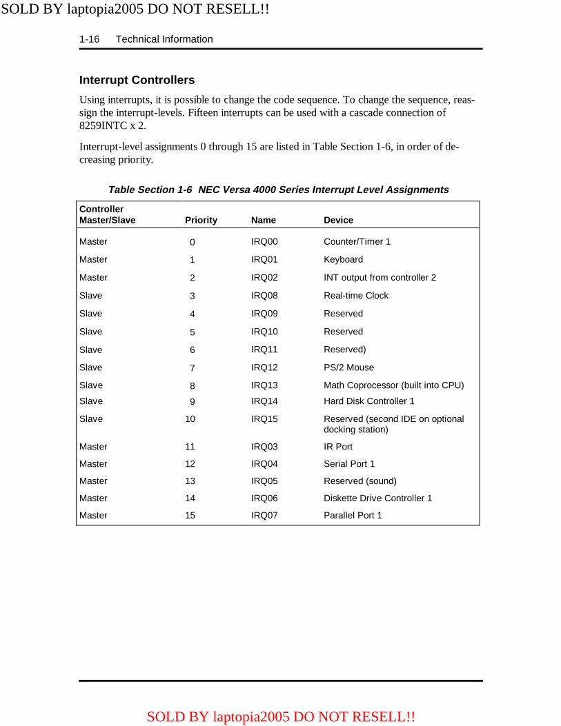
Interrupt Controllers
Using interrupts, it is possible to change the code sequence. To change the sequence, reas-sign the interrupt-levels. Fifteen interrupts can be used with a cascade connection of8259INTC x 2.
Interrupt-level assignments 0 through 15 are listed in Table Section 1-6, in order of de-creasing priority.
Table Section 1-6 NEC Versa 4000 Series Interrupt Level Assignments
ControllerMaster/Slave
Priority
Name
Device
Master 0 IRQ00 Counter/Timer 1
Master 1 IRQ01 Keyboard
Master 2 IRQ02 INT output from controller 2
Slave 3 IRQ08 Real-time Clock
Slave 4 IRQ09 Reserved
Slave 5 IRQ10 Reserved
Slave 6 IRQ11 Reserved)
Slave 7 IRQ12 PS/2 Mouse
Slave 8 IRQ13 Math Coprocessor (built into CPU)
Slave 9 IRQ14 Hard Disk Controller 1
Slave 10 IRQ15 Reserved (second IDE on optionaldocking station)
Master 11 IRQ03 IR Port
Master 12 IRQ04 Serial Port 1
Master 13 IRQ05 Reserved (sound)
Master 14 IRQ06 Diskette Drive Controller 1
Master 15 IRQ07 Parallel Port 1
SOLD BY laptopia2005 DO NOT RESELL!!
SOLD BY laptopia2005 DO NOT RESELL!!

Technical Information 1-17
POWER MANAGEMENT OVERVIEW
The NEC Versa 4000 series system uses power management features to prolong systembattery life.
The CPU implements a System Management Interrupt (SMI) function that works transpar-ently with the operating system and application software. When activated, the processormode changes to real mode. Unique “SM-RAM” containing power management software ismapped at address 30000h-3FFFFh. This activity is inherent to the system and does not re-quire any adjustment to the operating system or application software.
The power management program is located in ROM at location EA000h-0EFFFh. In on-board DRAM, the software is physically allocated at 0D0000h-0DFFFFh.
Use Auto Setup to select specific power management options. For information on how toselect these options, see Section 2.
NOTE: Some power management features areunavailable when an NEC docking station is con-nected.
System Power Management
The system power management consists of the following operation modes. These modesare:
� Active Mode In active mode, the system uses maximum power. It operateswith the default clock speed. The system continues to run at this speeds unlessoverwritten by the power management features.
� Suspend Mode When the system is powered on, but not in use it enters intoAutomatic Suspend mode after a specified amount of time (default timeout is 5minutes). This shut-down mechanism conserves system power while allowing theuser to return to complete the work at any time.
Or, the system can be put into Suspend mode using the suspend button. Press thesuspend button to activate Suspend mode; press it again to resume active mode.
Suspend mode causes the CPU power down, local devices to shut down, andregister values to be stored in RAM. System RAM is put into a slow refresh state.
SOLD BY laptopia2005 DO NOT RESELL!!
SOLD BY laptopia2005 DO NOT RESELL!!

1-18 Technical Information
Local Power Management
Use Auto Setup to select one of four power management settings for local devices. Theseinclude Longest Battery Life, Highest Performance, Custom Setup, and Power ManagementOff. The power management levels are also available during AC operation. The NEC Versa4000 computer ships with Longest Battery Life as the default power management setting.See Section 2 for specific procedures on using Auto Setup to select the power managementsettings.
When set to Longest Battery Life, CMOS will set local device timeout values, a local stand-by timeout value, and a suspend timeout value to ensure the longest battery life. The High-est Performance setting selects CMOS values that will provide minimal energy savings anda shorter battery life. The custom settings enable end-users to set the timeout values of theirchoice. The Power Management Off selection terminates all power management timers.
Local device timers in the system control power consumption in the LCD and Hard DiskDrive. Table Section 1-7 shows NEC Versa 4000 series Maximum Performance defaultpower management timers.
Table Section 1-7 Maximum Performance Default Settings
Power ManagementMode
Automatic Suspend Hard Disk Timer LCD Panel Timer
Longest Battery Life 10 minutes 30 seconds 2 minutes
Highest Performance 30 minutes 10 minutes 10 minutes
Custom 15 minutes 15 seconds 2 minutes
PLUG AND PLAY
The NEC Versa 4000 has a Plug and Play functionality. This means you can suspend thesystem, add an external keyboard, mouse, or monitor, and when you resume working, theNEC Versa 4000 recognizes the devices that have been connected to it. Similarly, you canremove external devices in Suspend mode and the NEC Versa 4000 notices the differencewhen resumed.
NOTE: A plug and play operating system andBIOS are required for this option to work.
SOLD BY laptopia2005 DO NOT RESELL!!
SOLD BY laptopia2005 DO NOT RESELL!!

Technical Information 1-19
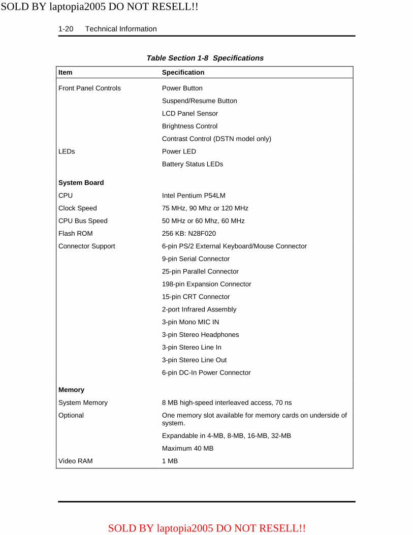
SPECIFICATIONS
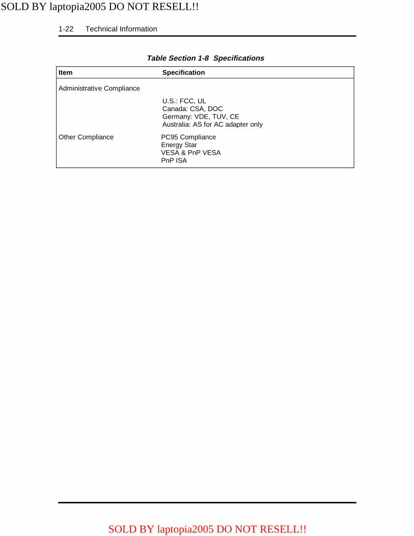
Table Section 1-8 provides a complete list of NEC Versa 4000 series system specifications.
Table Section 1-8 Specifications
Item Specification
Chassis Conf iguration
Size Width: 11.69 in. (297 mm)
Depth: 9.4 in. (240.5 mm)
Height: 2.1 in. (53.5 mm)
NEC Versa 4000 (DSTN)Weight: 6.25lb (2.84 kg) (Exact weight depends on options)
NEC Versa 4000/4050 (TFT)Weight: 6.58 lb (2.98 kg) (Exact weight depends on options)
NEC Versa 4000/4050 (High Resolution)Weight: 6.34 lb (2.87 kg) (Exact weight depends on options)
Keyboard PS/2 compatible, 83-key standard (79-key for UK andGermany) (includes Fn Key for ROM-based functions)
Device Slots Two PCMCIA slots that support up to two optional cards-oriented one on top of the other
One 3 1/2-inch x 0.75-inch high slot
One 3 1/2-inch x 0.75-inch high slot, front access, for standard1.44 diskette drive
One memory slot for optional memory card, located on bottomof system, in the hard disk drive bay
Power 100 to 240 Vac at 50 or 60 Hz
Output Voltage — 13.5 V DC, 3 A (40.5 W)
Battery Pack Weight .64 lb (0.29 kg)
Voltage 10.8 V
Capacity 2500 mAH
Battery Life Approximately 3 to 5 hours (depending onmodel and power management settings)
Bridge Battery Backs up memory contents up to 5 minutesusing Suspend Mode
SOLD BY laptopia2005 DO NOT RESELL!!
SOLD BY laptopia2005 DO NOT RESELL!!
1-20 Technical Information
Table Section 1-8 Specifications
Item Specification
Front Panel Controls Power Button
Suspend/Resume Button
LCD Panel Sensor
Brightness Control
Contrast Control (DSTN model only)
LEDs Power LED
Battery Status LEDs
System Board
CPU Intel Pentium P54LM
Clock Speed 75 MHz, 90 Mhz or 120 MHz
CPU Bus Speed 50 MHz or 60 Mhz, 60 MHz
Flash ROM 256 KB: N28F020
Connector Support 6-pin PS/2 External Keyboard/Mouse Connector
9-pin Serial Connector
25-pin Parallel Connector
198-pin Expansion Connector
15-pin CRT Connector
2-port Infrared Assembly
3-pin Mono MIC IN
3-pin Stereo Headphones
3-pin Stereo Line In
3-pin Stereo Line Out
6-pin DC-In Power Connector
Memory
System Memory 8 MB high-speed interleaved access, 70 ns
Optional One memory slot available for memory cards on underside ofsystem.
Expandable in 4-MB, 8-MB, 16-MB, 32-MB
Maximum 40 MB
Video RAM 1 MB
SOLD BY laptopia2005 DO NOT RESELL!!
SOLD BY laptopia2005 DO NOT RESELL!!
Technical Information 1-21
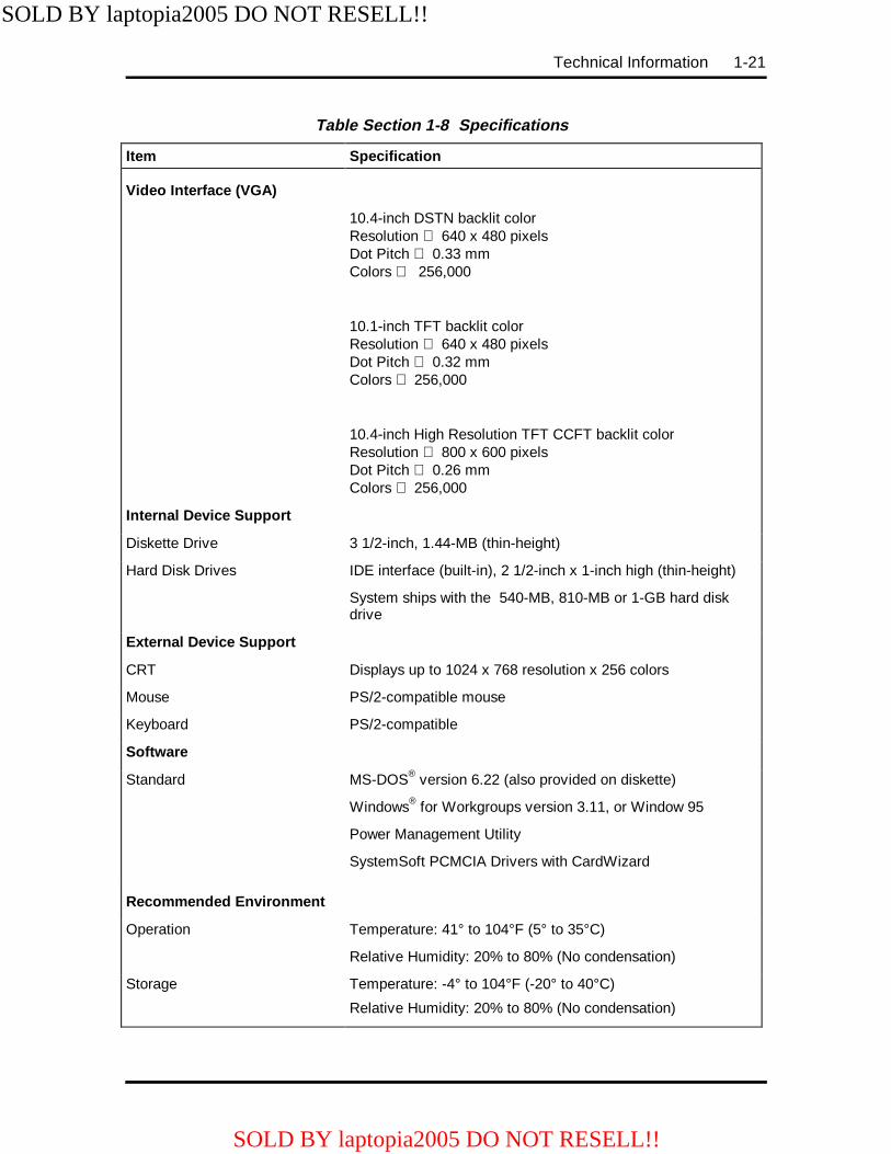
Table Section 1-8 Specifications
Item Specification
Video Interface (VGA)
10.4-inch DSTN backlit colorResolution 640 x 480 pixelsDot Pitch 0.33 mmColors 256,000
10.1-inch TFT backlit colorResolution 640 x 480 pixelsDot Pitch 0.32 mmColors 256,000
10.4-inch High Resolution TFT CCFT backlit colorResolution 800 x 600 pixelsDot Pitch 0.26 mmColors 256,000
Internal Device S upport
Diskette Drive 3 1/2-inch, 1.44-MB (thin-height)
Hard Disk Drives IDE interface (built-in), 2 1/2-inch x 1-inch high (thin-height)
System ships with the 540-MB, 810-MB or 1-GB hard diskdrive
External Device S upport
CRT Displays up to 1024 x 768 resolution x 256 colors
Mouse PS/2-compatible mouse
Keyboard PS/2-compatible
Software
Standard MS-DOS® version 6.22 (also provided on diskette)
Windows® for Workgroups version 3.11, or Window 95
Power Management Utility
SystemSoft PCMCIA Drivers with CardWizard
Recommended Environment
Operation Temperature: 41° to 104°F (5° to 35°C)
Relative Humidity: 20% to 80% (No condensation)
Storage Temperature: -4° to 104°F (-20° to 40°C)
Relative Humidity: 20% to 80% (No condensation)
SOLD BY laptopia2005 DO NOT RESELL!!
SOLD BY laptopia2005 DO NOT RESELL!!
1-22 Technical Information
Table Section 1-8 Specifications
Item Specification
Administrative Compliance
U.S.: FCC, ULCanada: CSA, DOCGermany: VDE, TUV, CEAustralia: AS for AC adapter only
Other Compliance PC95 ComplianceEnergy StarVESA & PnP VESAPnP ISA
SOLD BY laptopia2005 DO NOT RESELL!!
SOLD BY laptopia2005 DO NOT RESELL!!
Section 2
Setup and Operation
This section provides setup and operation information for the NEC Versa 4000 series sys-tem (including cabling, power-on verification and using Auto Setup).
UNPACKING THE SYSTEM
Find an area away from devices that generate strong magnetic fields (electric motors,transformers, etc.). Place the shipping carton on a sturdy surface and carefully unpack thesystem. The carton contents include the system, AC adapter, AC power cord, battery, soft-ware diskettes, and user documentation.
HARDWARE SETUP
When connecting power and signal cables, do the following.
1. Make sure that the system is powered off.
The power switch turns the system on or off. Slide the switch right to turn it on,slide the switch again to turn it off.
2. Observe connector alignment marks and keys (when present).
3. Connect the AC adapter cable to the power connector port as shown in FigureSection 2-8.
4. Connect the end of the power cord to the AC input connector on the AC adapter.
5. Connect the other end of the power cord to an AC power source.
NOTE: If operating the system on DC power,verify that the system has a charged battery packinstalled. For information on connecting the ACadapter to recharge the battery pack during orafter use, see “Recharging the Battery Pack” inthe following section.
6. Ensure that all connections are properly seated and secure.
7. When removing or replacing cables, grasp and pull gently on the attached con-nectors.
SOLD BY laptopia2005 DO NOT RESELL!!
SOLD BY laptopia2005 DO NOT RESELL!!

2-2 Setup and Operation
Cable Connections
Figure Section 2-1 shows the external connectors for the system. Where appropriate, securecables by tightening the cable holding screws.
Table Section 2-1 describes the I/O connectors on the rear of the system. For pin assign-ments, see Appendix A.
Figure Section 2-1 Power and I/O Connector Locations
Table Section 2-1 I/O Connector Descriptions
I/O Connector Function
Mouse/Keyboard Port Connects to a PS/2-style mouse, or a 101-key, external PS/2-stylekeyboard.
Serial Port Connects to an RS-232C device.
Enhanced Parallel Port Connects to a 25-pin parallel printer.
CRT Port Connects to a 15-pin external CRT.
IR Ports The infrared ports allow the user to transfer files between the NECVersa and an IR-equipped desktop, or print to an IR-equippedprinter without using cables.
Expansion Connector Provides a 75-pin connector to attach the optional NEC DockingStation 4000.
Power Connector This 4-pin connector provides an interface for the AC adapter. TheAC adapter is then connected to a wall outlet via the AC powercord.
Mouse/Keyboard Port
Serial Port
EnhancedParallel Port
CRT Port IR Port
Expansion Port
Power Port
SOLD BY laptopia2005 DO NOT RESELL!!
SOLD BY laptopia2005 DO NOT RESELL!!

Setup and Operation 2-3
OPERATING CONTROLS
The following section describes system controls, the LEDs, and function keys.
Refer to Figure Section 2-2 and Figure Section 2-3 to locate system controls and switches.Table Section 2-2 describes the controls.
Figure Section 2-2 Keyboard Panel Controls
Figure Section 2-3 Right Side Panel Controls
v Suspend Button Power Switch LCDSensor
Microphone
Volume Control
Brightness/ContrastControlKensington
Lock
SOLD BY laptopia2005 DO NOT RESELL!!
SOLD BY laptopia2005 DO NOT RESELL!!
2-4 Setup and Operation
Table Section 2-2 Control and Switch Functions
Control Function
Microphone Allows the user to record monophonic sound directly into the NECVersa 4000 system.
Suspend/ResumeButton
Press the button for Suspend mode, press again to resume activemode.
Power Switch Turns the system on when pushed to the right. Turns the system offwhen pushed to the right again..
LCD Sensor Senses when the LCD panel is closed, and turns off the panel.
Kensington Lock Enables the user to add an optional Kensington Lock.
Volume Control Controls the speaker volume.
Contrast Control Adjust the dark/light background on the LCD using this switch (onDSTN models only).
Brightness Control Move the control upward to increase brightness on the LCD. Lower thecontrol to decrease brightness on the LCD. A brighter adjustment usesmore battery power. For longer battery life, decrease the brightness.
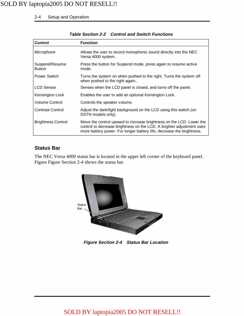
Status Bar
The NEC Versa 4000 status bar is located in the upper left corner of the keyboard panel.Figure Figure Section 2-4 shows the status bar.
Figure Section 2-4 Status Bar Location
StatusBar
SOLD BY laptopia2005 DO NOT RESELL!!
SOLD BY laptopia2005 DO NOT RESELL!!

Setup and Operation 2-5
Status Icons
The NEC Versa 4000 uses eight icons to let the user determine system status, see FigureSection 2-5.
Figure Section 2-5 Status Bar Icons
� Suspend — appears when the system is in Suspend mode.
� Power Management — shows current power management mode.
� Diskette — appears when the NEC Versa writes data to, or retrieves data from adiskette.
� Hard Disk — shows when the NEC Versa writes data to, or retrieves data fromthe system’s hard disk.
� Caps Lock — appears when caps lock is used.
� Scroll Lock — indicates that scroll lock is used.
� Num Lock — indicates that Num lock is used.
Battery Status
Battery icons (bars) also appear in the status bar. These bars represent the remaining batterycharge when the system is in use as follows:
� 4 bars signify a 76-100% charge
� 3 bars signify a 51-75% charge
� 2 bars signify a 26-50% charge
� 1 bar signifies a 0-25% charge
SuspendPower ManagementDiskette Drive AccessHard Disk Drive Access
Caps LockScroll LockNum Lock Battery
SOLD BY laptopia2005 DO NOT RESELL!!
SOLD BY laptopia2005 DO NOT RESELL!!
2-6 Setup and Operation
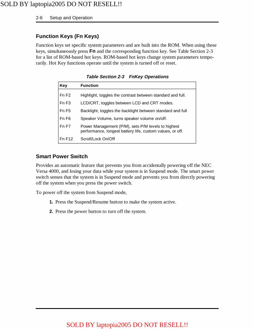
Function Keys (Fn Keys)
Function keys set specific system parameters and are built into the ROM. When using thesekeys, simultaneously press Fn and the corresponding function key. See Table Section 2-3for a list of ROM-based hot keys. ROM-based hot keys change system parameters tempo-rarily. Hot Key functions operate until the system is turned off or reset.
Table Section 2-3 FnKey Operations
Key Function
Fn F2 Highlight, toggles the contrast between standard and full.
Fn F3 LCD/CRT, toggles between LCD and CRT modes.
Fn F5 Backlight, toggles the backlight between standard and full
Fn F6 Speaker Volume, turns speaker volume on/off.
Fn F7 Power Management (P/M), sets P/M levels to highestperformance, longest battery life, custom values, or off.
Fn F12 Scroll/Lock On/Off
Smart Power Switch
Provides an automatic feature that prevents you from accidentally powering off the NECVersa 4000, and losing your data while your system is in Suspend mode. The smart powerswitch senses that the system is in Suspend mode and prevents you from directly poweringoff the system when you press the power switch.
To power off the system from Suspend mode,
1. Press the Suspend/Resume button to make the system active.
2. Press the power button to turn off the system.
SOLD BY laptopia2005 DO NOT RESELL!!
SOLD BY laptopia2005 DO NOT RESELL!!

Setup and Operation 2-7
Dip Switch
A four-position dip switch is located in the hard disk drive bay, under the hard disk drive,and next to the memory slot. Figure Section 2-6 shows the dip switch location. Figure Sec-tion 2-7 shows dip switch default settings.
Figure Section 2-6 Dip Switch Location
NOTE: The asterisk (*) below indicates thedefault setting.
Figure Section 2-7 Dip Switch Settings
Dip Switch
MemorySlot
BIOS REPROGRAM*ON: Prevents BIOS
reprogramming
PASSWORDON: Override*OFF: Available
*ON: U.S.OFF: International
KEYBOARD
RESERVED
ON
OFF
1 2 3 4
OFF: Allows BIOSreprogramming
SOLD BY laptopia2005 DO NOT RESELL!!
SOLD BY laptopia2005 DO NOT RESELL!!

2-8 Setup and Operation
POWER-ON SELF-TEST (POST)
Each time the system is powered on, the system checks the working status of componentsthrough an automatic power-on self-test (POST). The test checks the system configurationfor any discrepancies. One beep means that POST is successful. If any problems in datatransfer or hardware exist, an error message appears.
If the message is an Invalid Configuration message, press F2 to enter the Setup utility. Thesystem collects Setup data and lists the changes detected in the current parameter settings.Press Enter to review the settings, and make any necessary corrections. For more completeinformation, see “Using Setup to Select Parameters.”
If no error messages appear but the system still malfunctions, check the items in the list be-low.
� The power switch for each peripheral is on.
� All cables and power cords are tightly connected.
� The electrical outlet is working.
� The brightness and contrast controls for the display are adjusted properly.
� All options have been properly installed.
NOTE: If the system parameters (date, time,options, etc.) have not been entered for the pres-ent configuration, enter them when you completethe setup procedures (see “System Parameters”in this section).
SOLD BY laptopia2005 DO NOT RESELL!!
SOLD BY laptopia2005 DO NOT RESELL!!
Setup and Operation 2-9
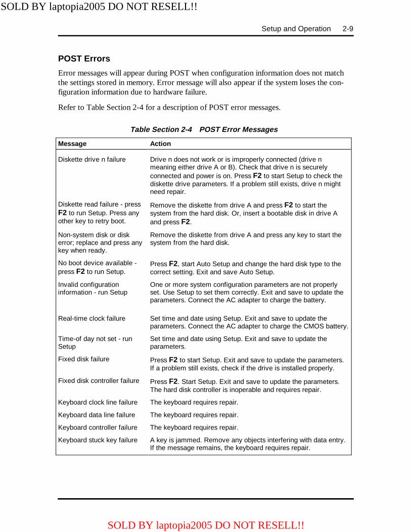
POST Errors
Error messages will appear during POST when configuration information does not matchthe settings stored in memory. Error message will also appear if the system loses the con-figuration information due to hardware failure.
Refer to Table Section 2-4 for a description of POST error messages.
Table Section 2-4 POST Error Messages
Message Action
Diskette drive n failure Drive n does not work or is improperly connected (drive nmeaning either drive A or B). Check that drive n is securelyconnected and power is on. Press F2 to start Setup to check thediskette drive parameters. If a problem still exists, drive n mightneed repair.
Diskette read failure - pressF2 to run Setup. Press anyother key to retry boot.
Remove the diskette from drive A and press F2 to start thesystem from the hard disk. Or, insert a bootable disk in drive Aand press F2.
Non-system disk or diskerror; replace and press anykey when ready.
Remove the diskette from drive A and press any key to start thesystem from the hard disk.
No boot device available -press F2 to run Setup.
Press F2, start Auto Setup and change the hard disk type to thecorrect setting. Exit and save Auto Setup.
Invalid configurationinformation - run Setup
One or more system configuration parameters are not properlyset. Use Setup to set them correctly. Exit and save to update theparameters. Connect the AC adapter to charge the battery.
Real-time clock failure Set time and date using Setup. Exit and save to update theparameters. Connect the AC adapter to charge the CMOS battery.
Time-of day not set - runSetup
Set time and date using Setup. Exit and save to update theparameters.
Fixed disk failure Press F2 to start Setup. Exit and save to update the parameters.If a problem still exists, check if the drive is installed properly.
Fixed disk controller failure Press F2. Start Setup. Exit and save to update the parameters.The hard disk controller is inoperable and requires repair.
Keyboard clock line failure The keyboard requires repair.
Keyboard data line failure The keyboard requires repair.
Keyboard controller failure The keyboard requires repair.
Keyboard stuck key failure A key is jammed. Remove any objects interfering with data entry.If the message remains, the keyboard requires repair.
SOLD BY laptopia2005 DO NOT RESELL!!
SOLD BY laptopia2005 DO NOT RESELL!!
2-10 Setup and Operation
NOTE: If a display related error occurs it is in-dicated by beeps. Display related errors usuallyrequire a system board replacement.
SETUP UTILITY
The Setup utility is a ROM-based program. It is functional when enabled (factory default).Setup automatically detects current system parameters during the power-on self-test(POST), described in the previous section. It also provides the following functions:
� sets date and time
� signals any hardware discrepancies during POST via error messages
� verifies that any optional memory that you installed was installed correctly
� integrates security features.
Setup also includes security features that protect your system from unauthorized use.
Accessing Setup
To access Setup, press F2 at the power-on prompt
With an Error at POST
You will need to use the Setup utility if the system detects an error during POST, itprompts you with double beep sound and a message: "Press <F2> to resume, <F2> forSetup". If you press F2, POST continues. If you want to fix the error, carefully read the er-ror message that appears above the prompt, and press F2.
After you press F2, the system displays the Setup Main menu.
With No Errors at POST
To enter Setup when no error message is displayed during POST, press F2 when theprompt appears.
After you press F2, the system displays the Setup Main screen. The main screen displaysthe current hardware parameters of your computer.
SOLD BY laptopia2005 DO NOT RESELL!!
SOLD BY laptopia2005 DO NOT RESELL!!
Setup and Operation 2-11
Setup Screen
The Setup screens have four main areas of information. These include:
� Top Line of the Screen — contains user-selectable menu options.
� Left Half of the Screen — provides current parameter information. Selecting a pa-rameter from the list (using the menu bar) toggles through selectable parametersettings.
� Right Half of the Screen — describes each parameter and the available settings.
� Bottom Line of the Screen — displays the keys that you can use to move the cur-sor or to select a particular function, such as saving parameters and exiting themenu.
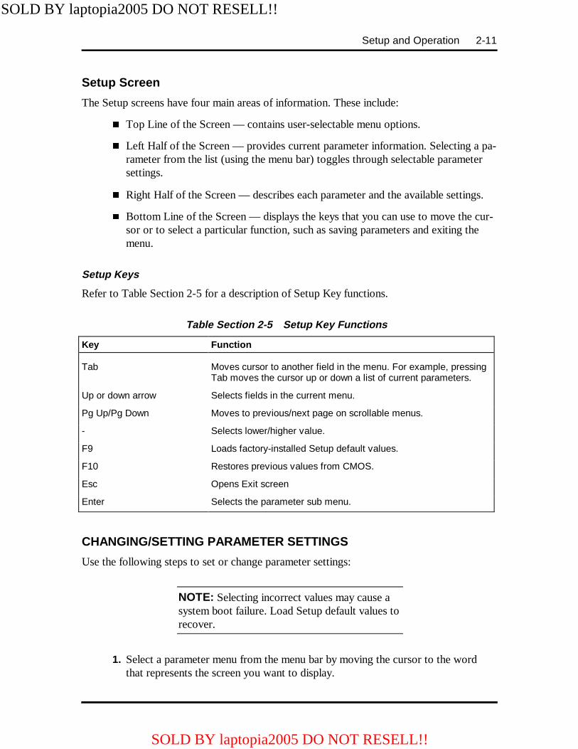
Setup Keys
Refer to Table Section 2-5 for a description of Setup Key functions.
Table Section 2-5 Setup Key Functions
Key Function
Tab Moves cursor to another field in the menu. For example, pressingTab moves the cursor up or down a list of current parameters.
Up or down arrow Selects fields in the current menu.
Pg Up/Pg Down Moves to previous/next page on scrollable menus.
- Selects lower/higher value.
F9 Loads factory-installed Setup default values.
F10 Restores previous values from CMOS.
Esc Opens Exit screen
Enter Selects the parameter sub menu.
CHANGING/SETTING PARAMETER SETTINGS
Use the following steps to set or change parameter settings:
NOTE: Selecting incorrect values may cause asystem boot failure. Load Setup default values torecover.
1. Select a parameter menu from the menu bar by moving the cursor to the wordthat represents the screen you want to display.
SOLD BY laptopia2005 DO NOT RESELL!!
SOLD BY laptopia2005 DO NOT RESELL!!
2-12 Setup and Operation
For example, to select "Peripherals," press the arrow key until the word Peripher-als is highlighted. A screen appears with the current setting for each peripheraldevice.
2. View the parameter settings by pressing the space bar or the + key. The choicesappear, toggling from one to another as you press.
3. When you reach the setting you want, leave it and move to the next parameter tobe changed.
4. When you are through viewing or changing parameters, press ESC to move tothe Exit screen.
5. The Exit screen displays a list of options. Press Enter to select "Save Changesand Exit". The screen displays a prompt confirming that the changes were made.
6. Press Continue . The system reboots with the saved changes.
SOLD BY laptopia2005 DO NOT RESELL!!
SOLD BY laptopia2005 DO NOT RESELL!!

Setup and Operation 2-13
PARAMETER OPTIONS
Refer to Table Section 2-6 for a complete list of the parameters selectable through Setup. Italso lists factory default settings in the mobile mode. Parameter descriptions follow the ta-ble. Menu selections for Setup are the same except where noted.
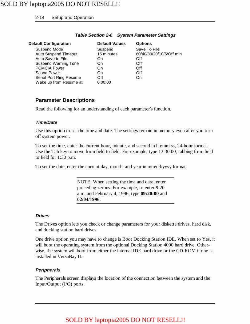
Table Section 2-6 System Parameter Settings
Default Configuration Default Values Options Main System Time System Date Diskette Drive A Diskette Drive B
HR:MIN:SECMO/DAY/YEAR1.44MB, 3.5"Not Installed
1.2MB, 5.25"/Not Installed1.44MB, 3.5"/1.2MB, 5.25"
Internal Hard Drives Master Slave
EnableAutoNone
DisableBIOS Defined/None/CD/UserBIOS Defined/Auto/CD/User
Docking Station Hard Drives: Master Slave
DisableNoneNone
EnableBIOS Defined/CD/User/AutoBIOS Defined/CD/User/Auto
Boot Docking Station IDE System Memory Extended Memory
No640K7168KB
Yes
11264KB (w/ 4MB card)15360KB (w/ 8MB card)23552KB (w/ 16MB card)39936KB (w/ 32MB card)12MB Memory card not supported
Peripherals Serial Port Infrared Location Infrared Serial Port Parallel Port Parallel Mode NumLock Keyboard auto-repeat rate Keyboard auto-repeat delay
EnabledRearCOM2LPT1UnidirectionalOff30/sec½ sec
Disabled/ReconfigurableFront/DisableReconfigurableLPT2/Reconfigurable/DisabledBi-Directional/EnhancedOn2/6/10/13/19/22/27¼, ¾, 1 sec
SecurityUser Password Set Password Password on boot Password on resume
DisabledPress EnterDisabledDisabled
EnabledEnabledEnabled
Power Savings Power Management under AC Power Savings Hard Disk Timeout Panel Backlight Video Timeout Serial Timeout Parallel Timeout CPU Power Save Standby Timeout
OffCustom Settings15 secAuto2 minutesOnOnOff2 minutes
OnHighest Performance/Longest Battery Life/OffOff, 15min/10/8/6/4/2/1/ 45sec/30/10Full/Standard4/6/8/10/15min/Off,/10/15/30/45secOffOffOn1/4/6/8/12/16 min/Off
SOLD BY laptopia2005 DO NOT RESELL!!
SOLD BY laptopia2005 DO NOT RESELL!!
2-14 Setup and Operation
Table Section 2-6 System Parameter Settings
Default Configuration Default Values Options Suspend Mode Auto Suspend Timeout Auto Save to File Suspend Warning Tone PCMCIA Power Sound Power Serial Port Ring Resume Wake up from Resume at:
Suspend15 minutesOnOnOnOnOff0:00:00
Save To File60/40/30/20/10/5/Off minOffOffOffOffOn
Parameter Descriptions
Read the following for an understanding of each parameter's function.
Time/Date
Use this option to set the time and date. The settings remain in memory even after you turnoff system power.
To set the time, enter the current hour, minute, and second in hh:mm:ss, 24-hour format.Use the Tab key to move from field to field. For example, type 13:30:00, tabbing from fieldto field for 1:30 p.m.
To set the date, enter the current day, month, and year in mm/dd/yyyy format.
NOTE: When setting the time and date, enterpreceding zeroes. For example, to enter 9:20a.m. and February 4, 1996, type 09:20:00 and02/04/1996.
Drives
The Drives option lets you check or change parameters for your diskette drives, hard disk,and docking station hard drives.
One drive option you may have to change is Boot Docking Station IDE. When set to Yes, itwill boot the operating system from the optional Docking Station 4000 hard drive. Other-wise, the system will boot from either the internal IDE hard drive or the CD-ROM if one isinstalled in VersaBay II.
Peripherals
The Peripherals screen displays the location of the connection between the system and theInput/Output (I/O) ports.
SOLD BY laptopia2005 DO NOT RESELL!!
SOLD BY laptopia2005 DO NOT RESELL!!

Setup and Operation 2-15
Security
The Security screen lets you set a password to protect your data by allowing your system toboot only after you enter a password.
When a system password is set, you must enter the password before you can enter Setup.This feature allows only an authorized user to change system parameters.
You are not prompted to enter a password until you set an initial password. Your system isnot protected until you enter the initial password.
See “Security Options” later in this section for instructions on setting and using the systempassword.
Power Savings
The Power Savings screen lets you select the level of power management, suspend mode,and suspend/resume options.
� Power Management Under AC Normally, whenever AC power is con-nected to the NEC Versa 4000, power management is disabled. If you enable thisoption, the system uses the power management mode (on or off) you set using thePower Management option.
� Power Savings A "Highest Performance" setting provides the greatest sys-tem performance. "Longest Battery Life" provides maximum power saving, and"Off" disables all power management timers. You can also customize the system'spower management by selecting "Custom Settings" and entering values for systemtimeouts.
� Suspend Mode Suspend mode has a method of operation called Sus-pend/Resume that stores information in RAM and maintains RAM contents aftershutting down all local devices. You also have the option to select Save to File.This saves all your open data files to a special file on the hard disk whenever thesystem goes into Suspend mode. All your data is automatically recovered fromwhere you left off when you Resume.
� Suspend Warning Tone This option lets you enable or disable a warningtone when Suspend mode starts. It is best to keep this option enabled.
� PCMCIA Power This option allows you to turn off power to the PCMCIAslots in order to save system power. The slot's power cannot be turned off if acard is installed in the slot.
SOLD BY laptopia2005 DO NOT RESELL!!
SOLD BY laptopia2005 DO NOT RESELL!!
2-16 Setup and Operation
SECURITY OPTIONS
The system supports two types of passwords for system security:
� system password
� keyboard lock hotkey.
The following contains instructions for setting and using the password feature.
System Password
Use the system password to lock the system at power-on. The system password is set usingSetup. This locks the keyboard to prevent unauthorized access to the system. When a sys-tem password is set, the password must be entered before entering Auto Setup. This featureallows only authorized access to system parameters.
See the following procedures to set an initial password.
1. Select the Security option in Setup.
2. Select "Set Password" by pressing Enter.
3. At the prompt, enter a password up to seven characters long. Another windowappears with a prompt to reenter your password for verification. Write yourpassword down and keep it in a secure place in case you forget it.
4. Press Enter to return to the Security screen.
5. Press ESC to save the changes and exit Setup.
Once you have set the password, you can select Enable on Boot. This means that each timeyou start up (boot) your NEC Versa, you'll be prompted for a password.
Using the System Password
After setting the initial password, a password prompt appears each time the system is pow-ered on. At the password prompt, enter your password and press Enter to load your oper-ating system or to enter Setup. The characters entered do not appear on the screen.
NOTE: If a system password is set, you can'tenter Setup until you enter the password.
If it takes more than three tries to enter the correct password, power off the system and tryagain. Repeat steps 1 and 2 above.
To remove a password, at the password prompt press Enter . Press Enter again when the re-enter prompt appears. Your password clears and you are no longer prompted to enter onewhen you power on the system.
SOLD BY laptopia2005 DO NOT RESELL!!
SOLD BY laptopia2005 DO NOT RESELL!!

Setup and Operation 2-17
Keyboard Lock Hotkey
The system supports a keyboard lock feature for additional security. The lock option ap-pears on the Setup screen only after you have enabled a password. At this point in Setup,the lock can be enabled or disabled.
To lock the keyboard, press Ctrl + Alt + Back Space . To unlock the keyboard, enter thepassword. If the password is removed, this option is no longer available.
BIOS UPDATE UTILITY (BUU)
The BIOS Update utility updates the ROM BIOS version of the system. This software util-ity updates the Flash ROM installed on the system board. The utility identifies and saves thecurrently installed BIOS version before installing the new version.
To receive the latest BUU diskette (in the U.S. only), call the Technical Support Center at(800) 632-4525 or download the BUU by logging onto NEC's Electronic Bulletin BoardSystem (BBS) and perform the procedures described in the following subsections.
To use the BIOS Update utility, the system configuration must be set to 640 KB of basememory with the programming voltage enabled.
Precautions
The BIOS Update utility diskette saves the old BIOS version. Make sure the diskette is notwrite-protected. If attempting to use a diskette that has updated another unit, a messagewarns that the original BIOS may not be restored. If updating more than one system, firstmake a copy of the original diskette for each system before using the diskette.
Downloading the Update Utility
To receive the latest version of the BIOS Update utility, perform the following steps.
1. Log onto NEC's BBS by dialing (508)-635-4706. The BBS parameters are asfollows.
� Baud rate: 300 to 14,400 Kbps
� Parity: none
� Data bits: 8� Stop bits: 1
2. Once connected, a name and password must be entered. When connecting for thefirst time, a questionnaire must be completed.
3. At the NEC/Technologies Bulletin Board main menu, type F and then press En-ter for the File Menu.
SOLD BY laptopia2005 DO NOT RESELL!!
SOLD BY laptopia2005 DO NOT RESELL!!

2-18 Setup and Operation
4. At the File Menu, type D and then press Enter for download.
5. Type the file name, L440nB3.EXE, and press Enter . Insert the correct revisionnumber in place of the n.
6. Press Enter again.
7. Set the default protocol on the BBS.
8. The BBS displays a prompt that it is ready to send the file. Perform the software'sdownload transfer procedure. The files are sent to the hard drive. Execute the fileto create a bootable disk. A message prompts you to insert a 1.44-MB diskettedrive in drive A. Make sure that it is a high-density diskette. Press any key tocontinue.
After pressing any key, the diskette is formatted and the BIOS update files arecopied to the diskette.
9. After the download is completed, log off the BBS.
NOTE: If you don’t know the filename, join thelaptop conference to find the BIOS or driver diskyou need.
Using the Update Utility
Load the BIOS Update utility as follows.
CAUTION: Never load a BUU from anothersystem model. That system's BIOS will be lost.
1. Power off the system unit.
2. Make sure Switch 1 on the dip switch is off.
3. Insert the BIOS Update Utility diskette into drive A.
4. Power on the system unit. The unit boots and automatically loads the utility. Amessage similar to the following appears:
FLASH ROM EQUIPPED
WARNING: The BIOS Update Procedureis about to begin, press ENTER to continue.To abort, remove the diskette and reset the unit.
SOLD BY laptopia2005 DO NOT RESELL!!
SOLD BY laptopia2005 DO NOT RESELL!!

Setup and Operation 2-19
5. Press Enter to continue. The utility checks the currently installed BIOS versionand the diskette's BIOS versions. If the BIOS can be updated, the Main Menu ap-pears (see the following screen). If there is a problem, the appropriate message isdisplayed.
NOTE: The Customize BIOS option shown inthe following menu is no longer available.
NEC BIOS Update UtilityMain Menu
InformationDisplay BIOS VersionCustomize BIOSInstall New BIOSRestore Original BIOSExit
SOLD BY laptopia2005 DO NOT RESELL!!
SOLD BY laptopia2005 DO NOT RESELL!!
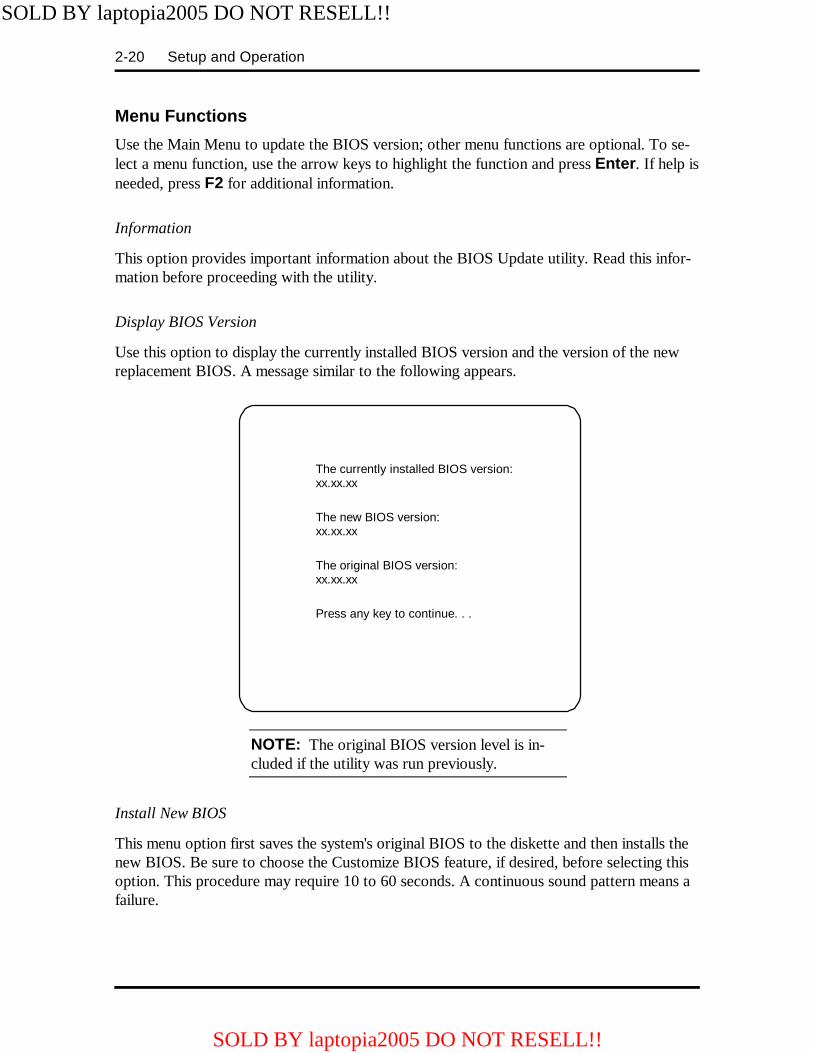
2-20 Setup and Operation
Menu Functions
Use the Main Menu to update the BIOS version; other menu functions are optional. To se-lect a menu function, use the arrow keys to highlight the function and press Enter . If help isneeded, press F2 for additional information.
Information
This option provides important information about the BIOS Update utility. Read this infor-mation before proceeding with the utility.
Display BIOS Version
Use this option to display the currently installed BIOS version and the version of the newreplacement BIOS. A message similar to the following appears.
NOTE: The original BIOS version level is in-cluded if the utility was run previously.
Install New BIOS
This menu option first saves the system's original BIOS to the diskette and then installs thenew BIOS. Be sure to choose the Customize BIOS feature, if desired, before selecting thisoption. This procedure may require 10 to 60 seconds. A continuous sound pattern means afailure.
The currently installed BIOS version:xx.xx.xx
The new BIOS version:xx.xx.xx
The original BIOS version:xx.xx.xx
Press any key to continue. . .
SOLD BY laptopia2005 DO NOT RESELL!!
SOLD BY laptopia2005 DO NOT RESELL!!
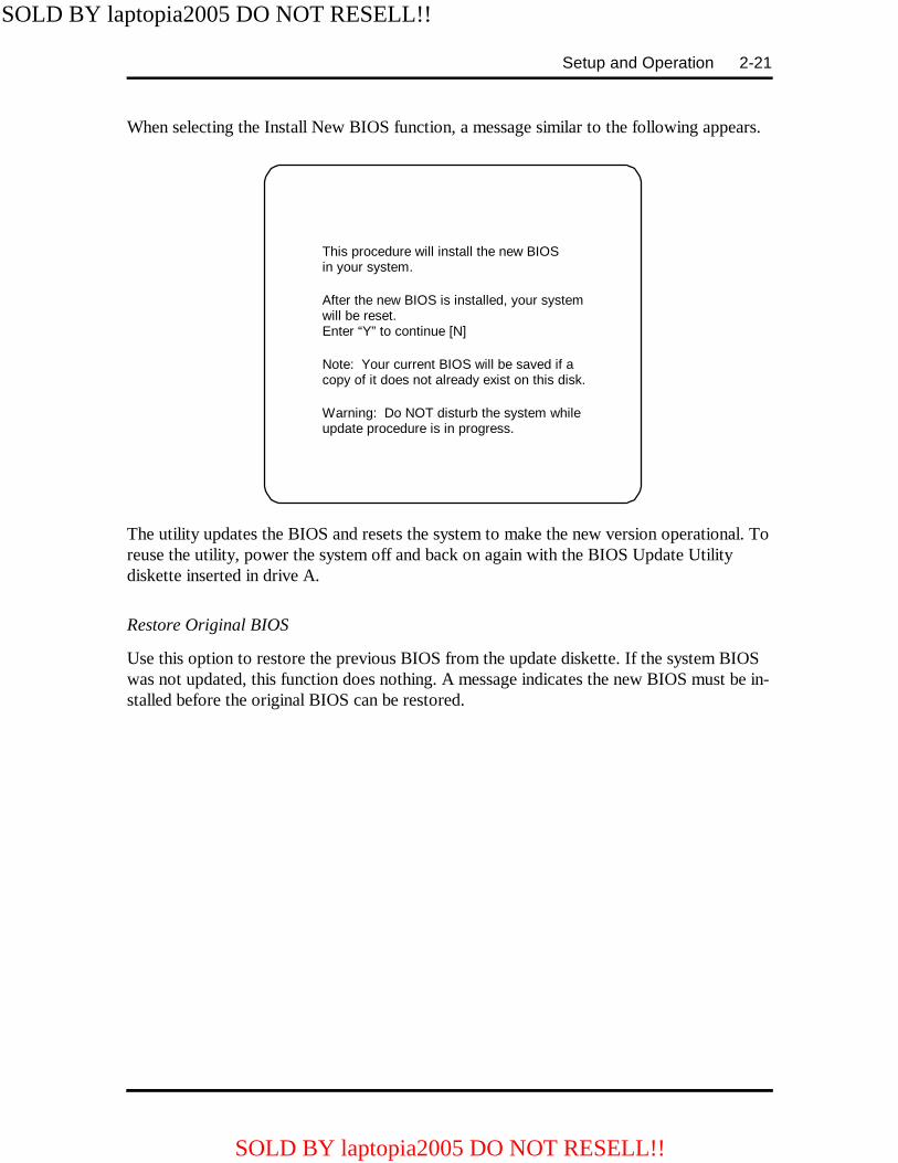
Setup and Operation 2-21
When selecting the Install New BIOS function, a message similar to the following appears.
The utility updates the BIOS and resets the system to make the new version operational. Toreuse the utility, power the system off and back on again with the BIOS Update Utilitydiskette inserted in drive A.
Restore Original BIOS
Use this option to restore the previous BIOS from the update diskette. If the system BIOSwas not updated, this function does nothing. A message indicates the new BIOS must be in-stalled before the original BIOS can be restored.
This procedure will install the new BIOSin your system.
After the new BIOS is installed, your systemwill be reset.Enter “Y” to continue [N]
Note: Your current BIOS will be saved if acopy of it does not already exist on this disk.
Warning: Do NOT disturb the system whileupdate procedure is in progress.
SOLD BY laptopia2005 DO NOT RESELL!!
SOLD BY laptopia2005 DO NOT RESELL!!
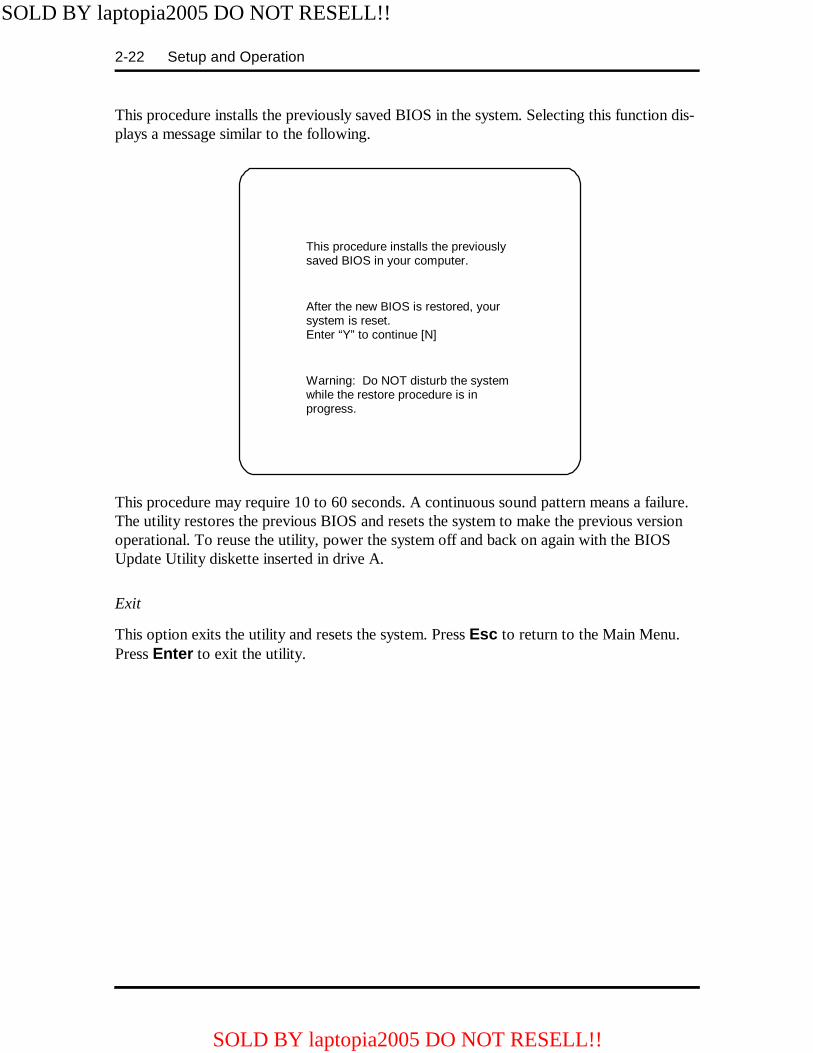
2-22 Setup and Operation
This procedure installs the previously saved BIOS in the system. Selecting this function dis-plays a message similar to the following.
This procedure may require 10 to 60 seconds. A continuous sound pattern means a failure.The utility restores the previous BIOS and resets the system to make the previous versionoperational. To reuse the utility, power the system off and back on again with the BIOSUpdate Utility diskette inserted in drive A.
Exit
This option exits the utility and resets the system. Press Esc to return to the Main Menu.Press Enter to exit the utility.
This procedure installs the previouslysaved BIOS in your computer.
After the new BIOS is restored, yoursystem is reset.Enter “Y” to continue [N]
Warning: Do NOT disturb the systemwhile the restore procedure is inprogress.
SOLD BY laptopia2005 DO NOT RESELL!!
SOLD BY laptopia2005 DO NOT RESELL!!

Setup and Operation 2-23
POWER SOURCES
For optimum performance and power conservation, use the AC adapter to power the NECVersa 4000 series system. Other power sources include the battery pack, the optional carDC adapter and the optional docking station .
AC Adapter
The AC adapter allows the system to operate with AC power, recharges the battery pack,and maintains the bridge battery. The internal backup battery allows the system to retainsystem parameter information.
NOTE: Make sure that the AC adapter is con-nected at all times. It will continue to charge thebattery pack and bridge battery during operationor when the system is turned off.
If the AC adapter is used primarily, remove the battery pack to reduce system weight.
CAUTION: Only use the AC adapter modelprovided with the NEC Versa 4000 series sys-tem.
Connect the AC adapter as follows:
1. Connect the adapter's DC cable to the power connector on the rear of the system.Connect the other end to the AC adapter.
Figure Section 2-8 Connecting the AC Adapter
SOLD BY laptopia2005 DO NOT RESELL!!
SOLD BY laptopia2005 DO NOT RESELL!!
2-24 Setup and Operation
2. Connect one end of the AC power cable to the AC adapter. Connect the other endof the AC power cable to a 100- to 240-volt, AC wall outlet.
Battery Power
A fully charged battery pack lasts approximately up t o 5 hours with Power Management,or 2.5 hours without Power Management.
When battery power is low, the battery outline on the battery status LCD blinks. If the sys-tem speaker is enabled, three low battery warning beeps are emitted. The actual amount ofbattery time depends on the use of power-saving features, the application, options installed,and the environment.
Refer to “Battery Status” in the “Operating Controls” section for information on determin-ing how much battery power is currently available.
When battery power is low, put your system in Suspend mode, remove the battery pack,and replace it with a fully charged Li-Ion battery. Or, recharge the battery pack as follows.
Recharging the Battery PackTo recharge the battery, leave the battery in the system and connect your NEC Versa to theAC adapter and wall outlet. If you connect the system to the AC power and continue to useit, the battery recharges in 2.5 to 7 hours. If you do not use the system while it is rechargingit takes about 2.5 hours.
REPLACING THE BATTERY PACK
To replace the battery pack with a fully charged battery, press the suspend button to acti-vate Suspend mode. It is not necessary to turn off system power as long as Suspend mode isactivated. The bridge battery maintains data and system status for up to 5 minutes while inSuspend mode. Use the steps below to install a charged battery pack.
1. If power is on, push the suspend button to put the system in Suspend mode. Thebridge battery saves the memory contents and system status.
2. Turn the NEC Versa 4000 over so that it is upside down with the front of thesystem facing you.
3. Remove the battery cover as follows:
� Locate the battery cover latch and slide it towards the front of the system
� Slide the cover about half an inch away from the system to align the covertabs and notches.
SOLD BY laptopia2005 DO NOT RESELL!!
SOLD BY laptopia2005 DO NOT RESELL!!
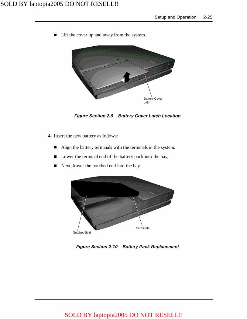
Setup and Operation 2-25
� Lift the cover up and away from the system.
Figure Section 2-9 Battery Cover Latch Location
4. Insert the new battery as follows:
� Align the battery terminals with the terminals in the system.
� Lower the terminal end of the battery pack into the bay,
� Next, lower the notched end into the bay.
Figure Section 2-10 Battery Pack Replacement
Battery CoverLatch
TerminalsNotched End
SOLD BY laptopia2005 DO NOT RESELL!!
SOLD BY laptopia2005 DO NOT RESELL!!
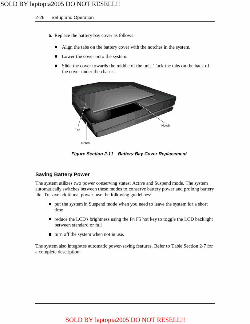
2-26 Setup and Operation
5. Replace the battery bay cover as follows:
� Align the tabs on the battery cover with the notches in the system.
� Lower the cover onto the system.
� Slide the cover towards the middle of the unit. Tuck the tabs on the back ofthe cover under the chassis.
Figure Section 2-11 Battery Bay Cover Replacement
Saving Battery Power
The system utilizes two power conserving states: Active and Suspend mode. The systemautomatically switches between these modes to conserve battery power and prolong batterylife. To save additional power, use the following guidelines:
� put the system in Suspend mode when you need to leave the system for a shorttime
� reduce the LCD's brightness using the Fn F5 hot key to toggle the LCD backlightbetween standard or full
� turn off the system when not in use.
The system also integrates automatic power-saving features. Refer to Table Section 2-7 fora complete description.
NotchTab
Notch
SOLD BY laptopia2005 DO NOT RESELL!!
SOLD BY laptopia2005 DO NOT RESELL!!
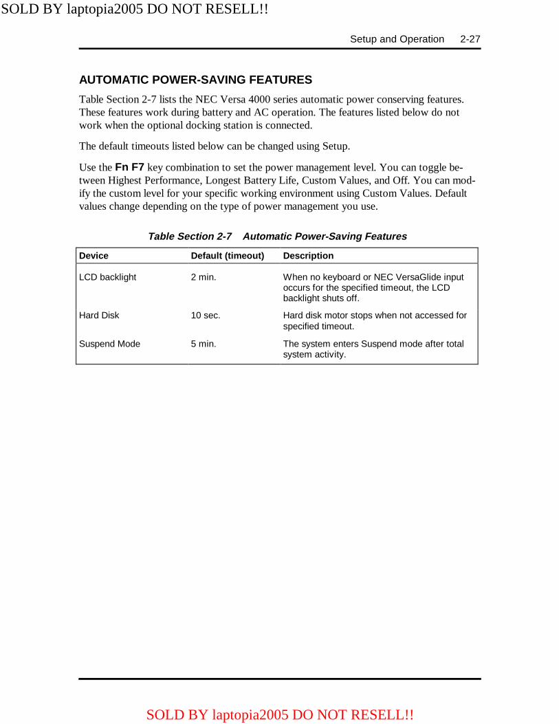
Setup and Operation 2-27
AUTOMATIC POWER-SAVING FEATURES
Table Section 2-7 lists the NEC Versa 4000 series automatic power conserving features.These features work during battery and AC operation. The features listed below do notwork when the optional docking station is connected.
The default timeouts listed below can be changed using Setup.
Use the Fn F7 key combination to set the power management level. You can toggle be-tween Highest Performance, Longest Battery Life, Custom Values, and Off. You can mod-ify the custom level for your specific working environment using Custom Values. Defaultvalues change depending on the type of power management you use.
Table Section 2-7 Automatic Power-Saving Features
Device Default (timeout) Description
LCD backlight 2 min. When no keyboard or NEC VersaGlide inputoccurs for the specified timeout, the LCDbacklight shuts off.
Hard Disk 10 sec. Hard disk motor stops when not accessed forspecified timeout.
Suspend Mode 5 min. The system enters Suspend mode after totalsystem activity.
SOLD BY laptopia2005 DO NOT RESELL!!
SOLD BY laptopia2005 DO NOT RESELL!!

Section 3
Illustrated Parts Breakdown
This subsection contains the illustrated parts breakdown (IPB) and NEC part numbers forthe NEC Versa 4000 series system. Table Section 3-1 lists field-replaceable parts and corre-sponding part numbers. Table Section 3-2 lists option and documentation part numbers.
NOTE: In the U.S., call 1(800) 632-4525 to or-der NEC spare parts. To order options in theU.S., call your local sales office.
Table Sect ion 3-1 NEC Versa 4000 Series Field-Replaceable Par ts*
Item Description Part Number
1 Battery Cover 136-237721-001A
2 PCMCIA Cover 136-237720-001A
3 Bottom Base Assembly 136-237714-011A
4 Expansion Port Cover 136-237719-001A
5 I/O Port Cover 136-237718-001A
6 I/O Board
7 Battery Charger Board 808-891789-001A
8 Sound Board (G8UNA) 158-026201-000C 9a 9b 9c
75 MHz CPU Board (G8TUN)90 MHz CPU Board (G8TUNA)120 MHz CPU Board
11 Keyboard (U.S.) 808-897250-001A 12 Infrared Rear Assembly (G8UAQ) 136-531163-A 13 Microphone/LED Board (G8UAR) 136-531164-A 14 NEC VersaGlide 808-874649-002A
Refer to online IPB Refer to online IPB Refer to online IPB
Refer to online IPB
SOLD BY laptopia2005 DO NOT RESELL!!
SOLD BY laptopia2005 DO NOT RESELL!!

3-2 Illustrated Parts Breakdown
Table Section 3-1 NEC Versa 4000 Series Field-Replaceable Parts*
Item Description Part Number
15 LCD Indicator 808-872191-003A
16a 16b 16c
LCD Base Assembly, includes speakers (C-SVGA)LCD Base Assembly, includes speakers (C-TFT)LCD Base Assembly, includes speakers (C-DSTN)
TBD136-237705-001A136-237706-001A
17 NEC Logo 136-600325-A
18 LCD Lock Spring 136-604300-A
19 LCD Lock Shaft 136-617799-A
20 LCD Lock 136-617798-001A
21a LCD Cover (SVGA) 136-617796-001A
21b LCD Cover (TFT) 136-237711-001A
21c LCD Cover (DSTN) 136-237712-001A
22 Intel Inside Sticker 158-030412-001A
23a NEC Versa 4000 Logo (SVGA) 158-030781-002
23b NEC Versa 4000 Logo (TFT) 158-030781-001
23c NEC Versa 4000 Logo (DSTN) 158-030781-000
24 Top Cover Assembly 136-237713-011A
25 AC Adapter 808-891790-001A
26 AC Power Cord (U.S.) 808-741299-001A
27 CMOS Battery 804-021107-003A
28 Infrared Front Assembly (G8UAP) 136-531162-A
29 Speaker 802-870018-006A
30 Bridge Battery 804-021205-001A
31a 360-MB Hard Disk Drive 136-237726-001A
31b 540-MB Hard Disk Drive 136-237726-002A
31c 720-MB Hard Disk Drive 136-237726-003A
32 Hard Disk Drive Cover 136-237722-001A
33 3 1/2-inch Diskette Drive 136-237724-001A
34 Main Battery (Lithium Ion) 804-021204-001A
35* Knob Volume 136-607428-001A
36* Rubber Foot 808-814221-039A
37* CD-ROM Drive 136-267770-001A
* Not shown in IPB figure
SOLD BY laptopia2005 DO NOT RESELL!!
SOLD BY laptopia2005 DO NOT RESELL!!

Illustrated Parts Breakdown 3-3
Figure Section 3-1 NEC Versa 4000 Series Illustrated Parts Breakdown*
____________* This data was prepared January 1998. For an up-to-date listing of spare parts, please call FaxFlash
(888) 329-0088 and order document number 42200013.
SOLD BY laptopia2005 DO NOT RESELL!!
SOLD BY laptopia2005 DO NOT RESELL!!
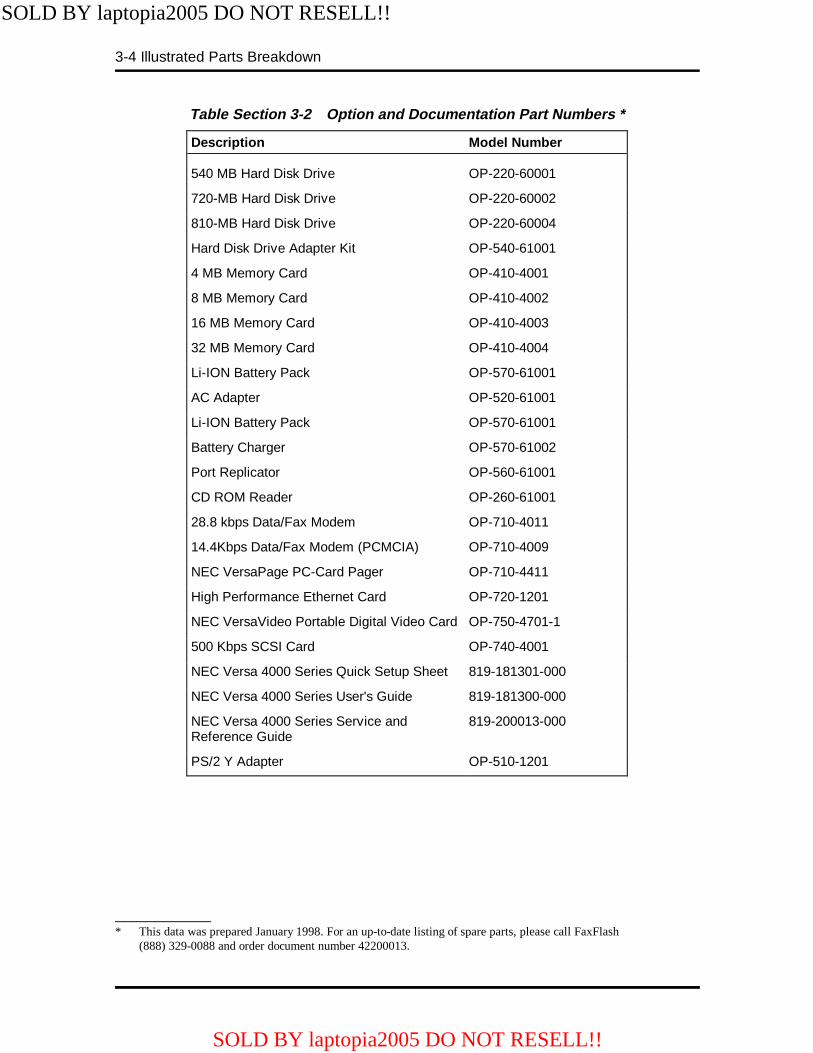
3-4 Illustrated Parts Breakdown
Table Section 3-2 Option and Documentation Part Numbers *
Description Model Number
540 MB Hard Disk Drive OP-220-60001
720-MB Hard Disk Drive OP-220-60002
810-MB Hard Disk Drive OP-220-60004
Hard Disk Drive Adapter Kit OP-540-61001
4 MB Memory Card OP-410-4001
8 MB Memory Card OP-410-4002
16 MB Memory Card OP-410-4003
32 MB Memory Card OP-410-4004
Li-ION Battery Pack OP-570-61001
AC Adapter OP-520-61001
Li-ION Battery Pack OP-570-61001
Battery Charger OP-570-61002
Port Replicator OP-560-61001
CD ROM Reader OP-260-61001
28.8 kbps Data/Fax Modem OP-710-4011
14.4Kbps Data/Fax Modem (PCMCIA) OP-710-4009
NEC VersaPage PC-Card Pager OP-710-4411
High Performance Ethernet Card OP-720-1201
NEC VersaVideo Portable Digital Video Card OP-750-4701-1
500 Kbps SCSI Card OP-740-4001
NEC Versa 4000 Series Quick Setup Sheet 819-181301-000
NEC Versa 4000 Series User's Guide 819-181300-000
NEC Versa 4000 Series Service andReference Guide
819-200013-000
PS/2 Y Adapter OP-510-1201
____________* This data was prepared January 1998. For an up-to-date listing of spare parts, please call FaxFlash
(888) 329-0088 and order document number 42200013.
SOLD BY laptopia2005 DO NOT RESELL!!
SOLD BY laptopia2005 DO NOT RESELL!!
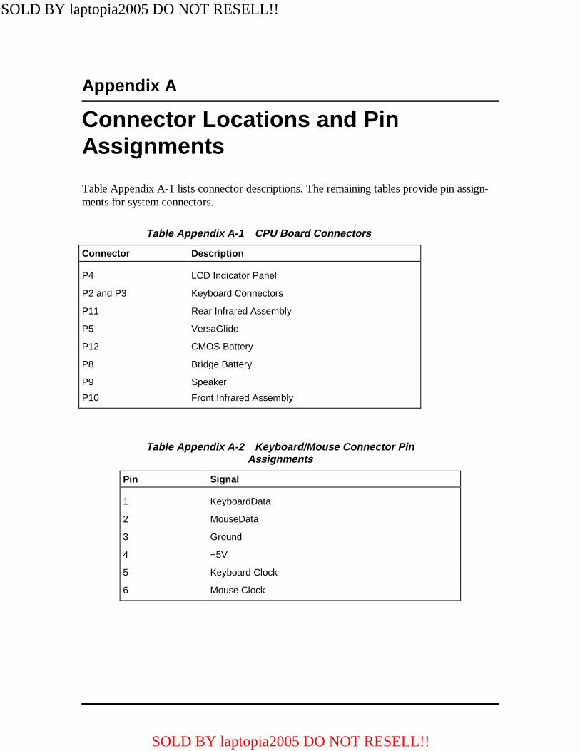
Appendix A
Connector Locations and PinAssignments
Table Appendix A-1 lists connector descriptions. The remaining tables provide pin assign-ments for system connectors.
Table Appendix A-1 CPU Board Connectors
Connector Description
P4 LCD Indicator Panel
P2 and P3 Keyboard Connectors
P11 Rear Infrared Assembly
P5 VersaGlide
P12 CMOS Battery
P8 Bridge Battery
P9 Speaker
P10 Front Infrared Assembly
Table Appendix A-2 Keyboard/Mouse Connector PinAssignments
Pin Signal
1 KeyboardData
2 MouseData
3 Ground
4 +5V
5 Keyboard Clock
6 Mouse Clock
SOLD BY laptopia2005 DO NOT RESELL!!
SOLD BY laptopia2005 DO NOT RESELL!!
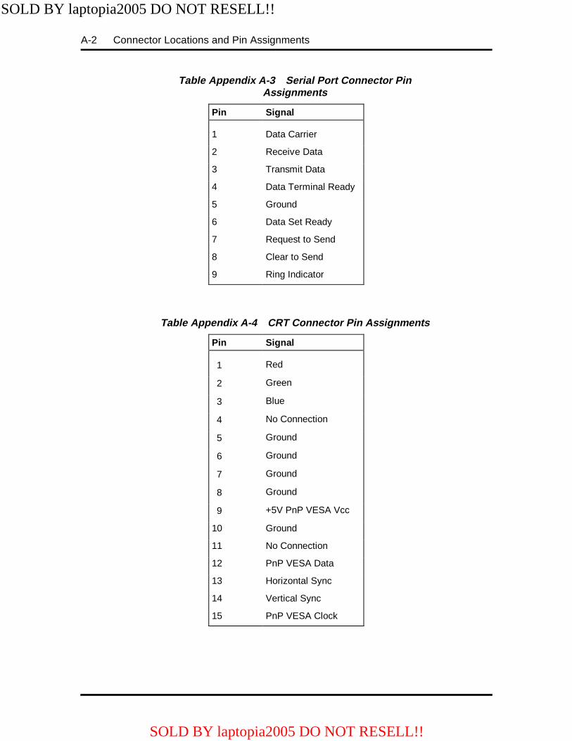
A-2 Connector Locations and Pin Assignments
Table Appendix A-3 Serial Port Connector PinAssignments
Pin Signal
1 Data Carrier
2 Receive Data
3 Transmit Data
4 Data Terminal Ready
5 Ground
6 Data Set Ready
7 Request to Send
8 Clear to Send
9 Ring Indicator
Table Appendix A-4 CRT Connector Pin Assignments
Pin Signal
1 Red
2 Green
3 Blue
4 No Connection
5 Ground
6 Ground
7 Ground
8 Ground
9 +5V PnP VESA Vcc
10 Ground
11 No Connection
12 PnP VESA Data
13 Horizontal Sync
14 Vertical Sync
15 PnP VESA Clock
SOLD BY laptopia2005 DO NOT RESELL!!
SOLD BY laptopia2005 DO NOT RESELL!!

Connector Locations and Pin Assignments A-3
Table Appendix A-5 Parallel Printer Pin Assignments
Pin Signal
1 - Strobe
2 Data Bit 0
3 Data Bit 1
4 Data Bit 2
5 Data Bit 3
6 Data Bit 4
7 Data Bit 5
8 Data Bit 6
9 Data Bit 7
10 - Acknowledge
11 Busy
12 PE
13 Select
14 - Auto Feed XT
15 - Error
16 - Initialize
17 - Select In
18 -25 Ground
SOLD BY laptopia2005 DO NOT RESELL!!
SOLD BY laptopia2005 DO NOT RESELL!!
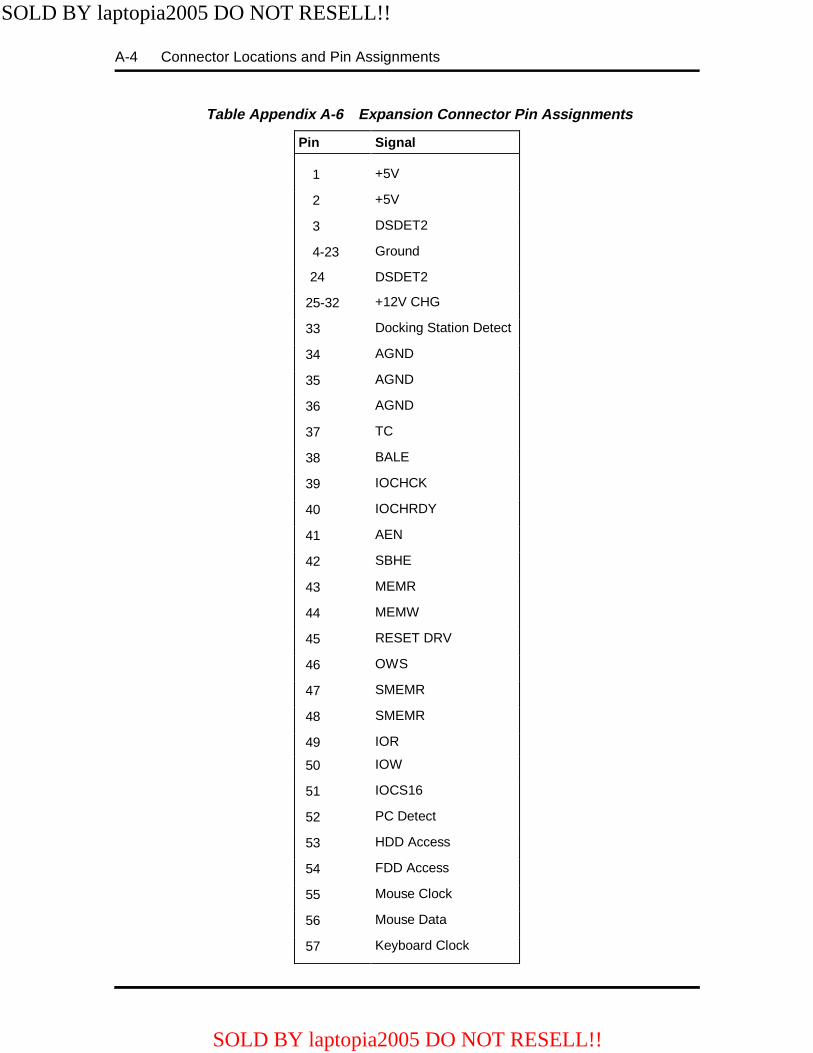
A-4 Connector Locations and Pin Assignments
Table Appendix A-6 Expansion Connector Pin Assignments
Pin Signal
1 +5V
2 +5V
3 DSDET2
4-23 Ground
24 DSDET2
25-32 +12V CHG
33 Docking Station Detect
34 AGND
35 AGND
36 AGND
37 TC
38 BALE
39 IOCHCK
40 IOCHRDY
41 AEN
42 SBHE
43 MEMR
44 MEMW
45 RESET DRV
46 OWS
47 SMEMR
48 SMEMR
49 IOR
50 IOW
51 IOCS16
52 PC Detect
53 HDD Access
54 FDD Access
55 Mouse Clock
56 Mouse Data
57 Keyboard Clock
SOLD BY laptopia2005 DO NOT RESELL!!
SOLD BY laptopia2005 DO NOT RESELL!!
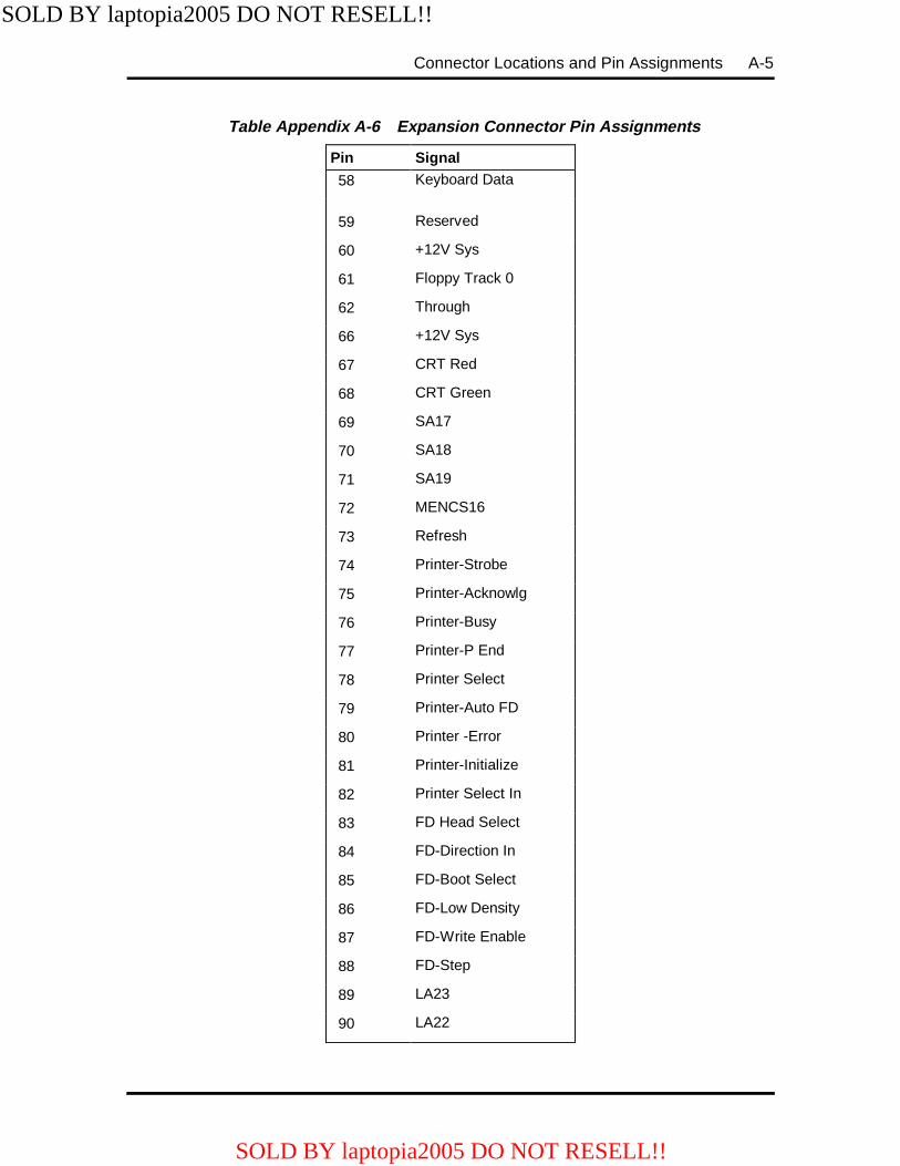
Connector Locations and Pin Assignments A-5
Table Appendix A-6 Expansion Connector Pin Assignments
Pin Signal
58 Keyboard Data
59 Reserved
60 +12V Sys
61 Floppy Track 0
62 Through
66 +12V Sys
67 CRT Red
68 CRT Green
69 SA17
70 SA18
71 SA19
72 MENCS16
73 Refresh
74 Printer-Strobe
75 Printer-Acknowlg
76 Printer-Busy
77 Printer-P End
78 Printer Select
79 Printer-Auto FD
80 Printer -Error
81 Printer-Initialize
82 Printer Select In
83 FD Head Select
84 FD-Direction In
85 FD-Boot Select
86 FD-Low Density
87 FD-Write Enable
88 FD-Step
89 LA23
90 LA22
SOLD BY laptopia2005 DO NOT RESELL!!
SOLD BY laptopia2005 DO NOT RESELL!!
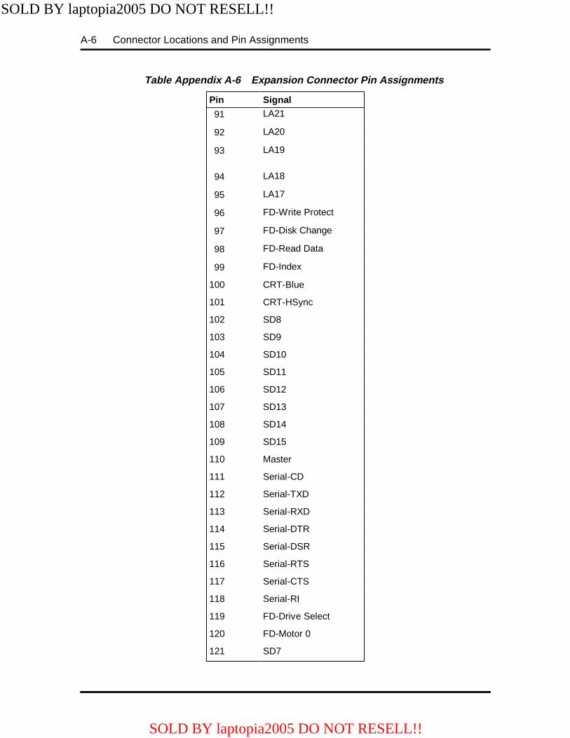
A-6 Connector Locations and Pin Assignments
Table Appendix A-6 Expansion Connector Pin Assignments
Pin Signal
91 LA21
92 LA20
93 LA19
94 LA18
95 LA17
96 FD-Write Protect
97 FD-Disk Change
98 FD-Read Data
99 FD-Index
100 CRT-Blue
101 CRT-HSync
102 SD8
103 SD9
104 SD10
105 SD11
106 SD12
107 SD13
108 SD14
109 SD15
110 Master
111 Serial-CD
112 Serial-TXD
113 Serial-RXD
114 Serial-DTR
115 Serial-DSR
116 Serial-RTS
117 Serial-CTS
118 Serial-RI
119 FD-Drive Select
120 FD-Motor 0
121 SD7
SOLD BY laptopia2005 DO NOT RESELL!!
SOLD BY laptopia2005 DO NOT RESELL!!
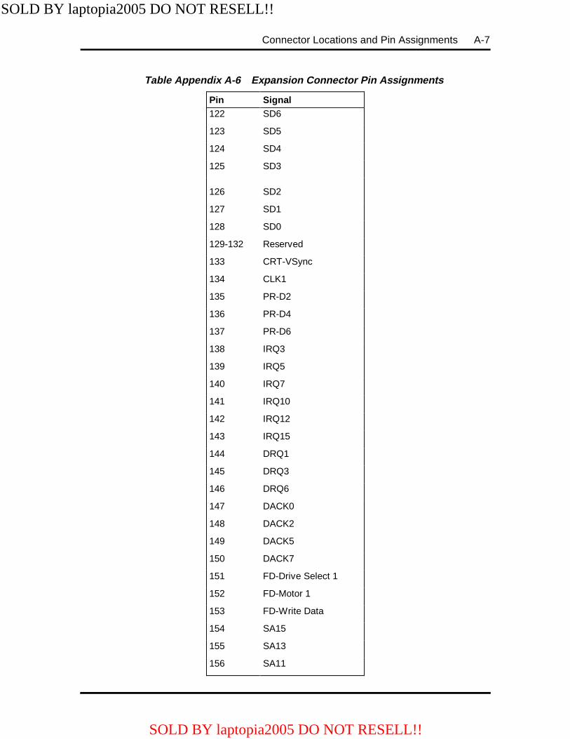
Connector Locations and Pin Assignments A-7
Table Appendix A-6 Expansion Connector Pin Assignments
Pin Signal 122 SD6
123 SD5
124 SD4
125 SD3
126 SD2
127 SD1
128 SD0
129-132 Reserved
133 CRT-VSync
134 CLK1
135 PR-D2
136 PR-D4
137 PR-D6
138 IRQ3
139 IRQ5
140 IRQ7
141 IRQ10
142 IRQ12
143 IRQ15
144 DRQ1
145 DRQ3
146 DRQ6
147 DACK0
148 DACK2
149 DACK5
150 DACK7
151 FD-Drive Select 1
152 FD-Motor 1
153 FD-Write Data
154 SA15
155 SA13
156 SA11
SOLD BY laptopia2005 DO NOT RESELL!!
SOLD BY laptopia2005 DO NOT RESELL!!
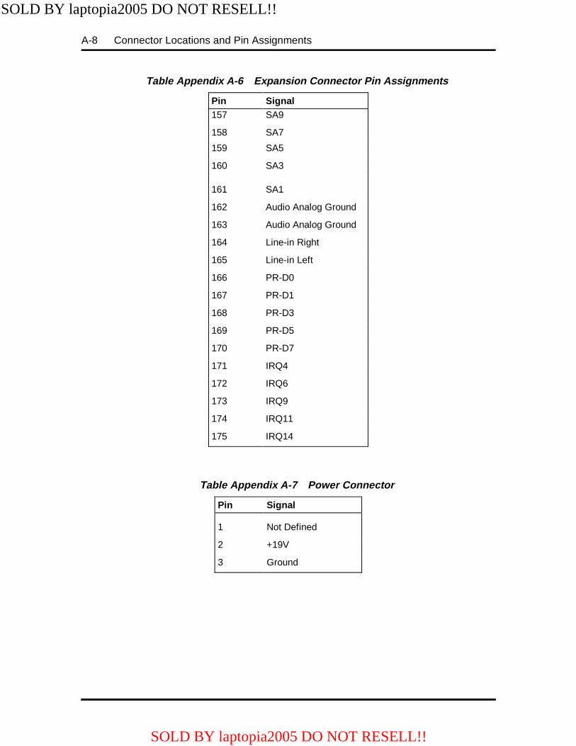
A-8 Connector Locations and Pin Assignments
Table Appendix A-6 Expansion Connector Pin Assignments
Pin Signal 157 SA9
158 SA7
159 SA5
160 SA3
161 SA1
162 Audio Analog Ground
163 Audio Analog Ground
164 Line-in Right
165 Line-in Left
166 PR-D0
167 PR-D1
168 PR-D3
169 PR-D5
170 PR-D7
171 IRQ4
172 IRQ6
173 IRQ9
174 IRQ11
175 IRQ14
Table Appendix A-7 Power Connector
Pin Signal
1 Not Defined
2 +19V
3 Ground
SOLD BY laptopia2005 DO NOT RESELL!!
SOLD BY laptopia2005 DO NOT RESELL!!
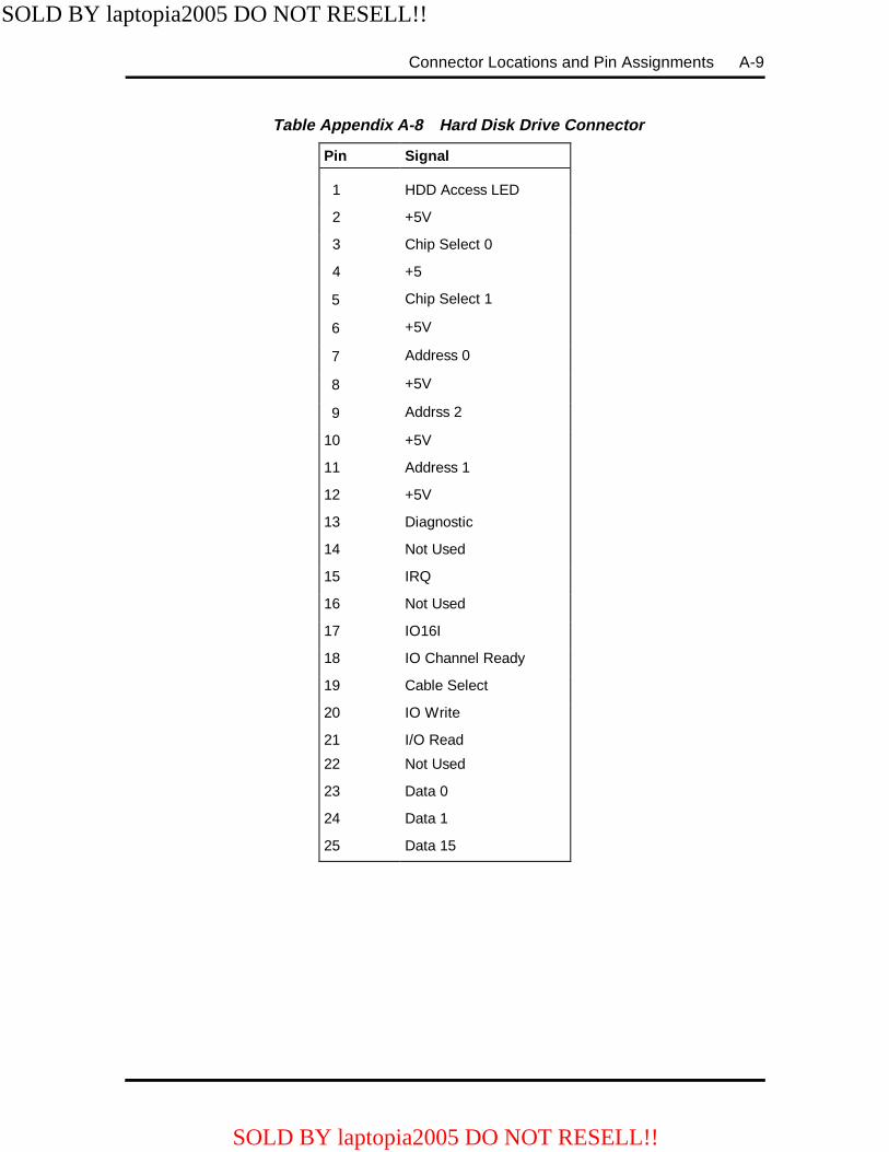
Connector Locations and Pin Assignments A-9
Table Appendix A-8 Hard Disk Drive Connector
Pin Signal
1 HDD Access LED
2 +5V
3 Chip Select 0
4 +5
5 Chip Select 1
6 +5V
7 Address 0
8 +5V
9 Addrss 2
10 +5V
11 Address 1
12 +5V
13 Diagnostic
14 Not Used
15 IRQ
16 Not Used
17 IO16I
18 IO Channel Ready
19 Cable Select
20 IO Write
21 I/O Read
22 Not Used
23 Data 0
24 Data 1
25 Data 15
SOLD BY laptopia2005 DO NOT RESELL!!
SOLD BY laptopia2005 DO NOT RESELL!!
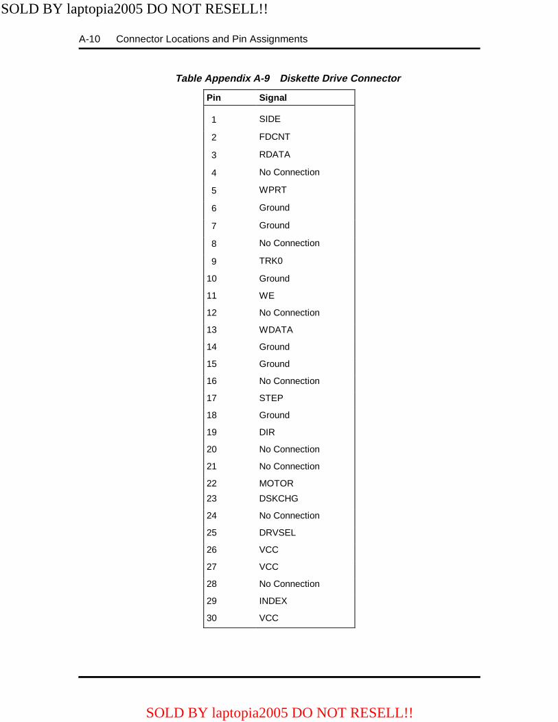
A-10 Connector Locations and Pin Assignments
Table Appendix A-9 Diskette Drive Connector
Pin Signal
1 SIDE
2 FDCNT
3 RDATA
4 No Connection
5 WPRT
6 Ground
7 Ground
8 No Connection
9 TRK0
10 Ground
11 WE
12 No Connection
13 WDATA
14 Ground
15 Ground
16 No Connection
17 STEP
18 Ground
19 DIR
20 No Connection
21 No Connection
22 MOTOR
23 DSKCHG
24 No Connection
25 DRVSEL
26 VCC
27 VCC
28 No Connection
29 INDEX
30 VCC
SOLD BY laptopia2005 DO NOT RESELL!!
SOLD BY laptopia2005 DO NOT RESELL!!
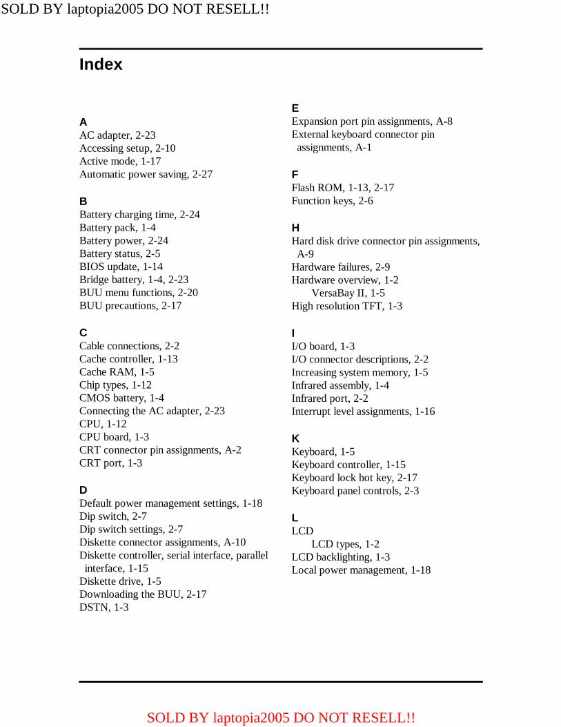
Index
AAC adapter, 2-23Accessing setup, 2-10Active mode, 1-17Automatic power saving, 2-27
BBattery charging time, 2-24Battery pack, 1-4Battery power, 2-24Battery status, 2-5BIOS update, 1-14Bridge battery, 1-4, 2-23BUU menu functions, 2-20BUU precautions, 2-17
CCable connections, 2-2Cache controller, 1-13Cache RAM, 1-5Chip types, 1-12CMOS battery, 1-4Connecting the AC adapter, 2-23CPU, 1-12CPU board, 1-3CRT connector pin assignments, A-2CRT port, 1-3
DDefault power management settings, 1-18Dip switch, 2-7Dip switch settings, 2-7Diskette connector assignments, A-10Diskette controller, serial interface, parallelinterface, 1-15
Diskette drive, 1-5Downloading the BUU, 2-17DSTN, 1-3
EExpansion port pin assignments, A-8External keyboard connector pinassignments, A-1
FFlash ROM, 1-13, 2-17Function keys, 2-6
HHard disk drive connector pin assignments,A-9
Hardware failures, 2-9Hardware overview, 1-2
VersaBay II, 1-5High resolution TFT, 1-3
II/O board, 1-3I/O connector descriptions, 2-2Increasing system memory, 1-5Infrared assembly, 1-4Infrared port, 2-2Interrupt level assignments, 1-16
KKeyboard, 1-5Keyboard controller, 1-15Keyboard lock hot key, 2-17Keyboard panel controls, 2-3
LLCD
LCD types, 1-2LCD backlighting, 1-3Local power management, 1-18
SOLD BY laptopia2005 DO NOT RESELL!!
SOLD BY laptopia2005 DO NOT RESELL!!

Index-2
MMemory
cache RAM, 1-5Memory map, 1-6Microprocessor, 1-1, 1-12Multimedia, 1-2
NNEC Versa 4000 parts list, 3-1NEC Versa 4000 system specifications, 1-19
OOperating controls, 2-3Option part numbers, 3-4
PParallel interface enhanced capabilitiesport, 1-11
Parallel port pin assignments, A-3Parameter descriptions, 2-14Parameter settings, 2-13Parameters
drives, 2-14peripherals, 2-14Power savings, 2-15security, 2-15time/date, 2-14
PCMCIA controller, 1-15PCMCIA Slots, 1-5Pentium, 1-1Plug and play, 1-18Post error messages, 2-9Post errors, 2-9Power connector pin assignments, A-8Power management modes
active, 1-17local standby, 1-17suspend, 1-17
Power management overview, 1-17Power management settings
default, 1-18Power sources, 2-23Power switch, 2-4Power-on self test (POST), 2-8
RRear panel connectors, 1-2Recharging the battery pack, 2-24Replacing the battery pack, 2-24ROM BIOS, 1-14
SSaving battery power, 2-26Security options, 2-16Serial interface, 1-12Serial port connector pin assignments, A-2Setup keys, 2-11Setup screen, 2-11Setup utility, 2-10Side panel controls, 2-3Smart power switch, 2-6Sound board, 1-3Status bar, 2-4Suspend mode, 1-17, 2-24System board connectors, A-1System configurations, 1-1System features, 1-1System icons, 2-5System logic, 1-13System memory, 1-5System parameters, 2-8System password, 2-16System setup, 2-1System status
icons, 2-5System video, 1-7
TTFT, 1-3Time/Date, 2-14
UUnpacking, 2-1Using the system password, 2-16Using the update utility, 2-18
SOLD BY laptopia2005 DO NOT RESELL!!
SOLD BY laptopia2005 DO NOT RESELL!!
Index-3
VVersaBay II, 1-5VersaGlide, 1-5VGA controller, 1-14Video controller architecture, 1-15Video mode
640x480 DSTN, simultaneous CRT,1-10
640x480 TFT, simultaneous CRT, 1-9CRT only, 1-7
Video RAM, 1-7
SOLD BY laptopia2005 DO NOT RESELL!!
SOLD BY laptopia2005 DO NOT RESELL!!