SolarEdge System Design and the NEC Three Phase Inverter System Design and the ... in Section 64-018...
12
White Paper SolarEdge Three Phase Inverter System Design and the Canadian Electrical Code June 2015 Revision 1.2 Shalhevet Bar-Asher; SolarEdge Technologies, Inc. Bill Brooks, PE; Brooks Engineering LLC References to CEC Articles are copyrighted by: Canadian Electrical Code, Part I 22 nd Edition 2012 Property of SolarEdge Technologies, Inc. ©Copyright 2013
Transcript of SolarEdge System Design and the NEC Three Phase Inverter System Design and the ... in Section 64-018...

White Paper
SolarEdge Three Phase Inverter System Design
and the Canadian Electrical Code
June 2015
Revision 1.2
Shalhevet Bar-Asher; SolarEdge Technologies, Inc.
Bill Brooks, PE; Brooks Engineering LLC
References to CEC Articles are copyrighted by:
Canadian Electrical Code, Part I 22nd Edition 2012
Property of SolarEdge Technologies, Inc. ©Copyright 2013

SolarEdge Three Phase Inverter Sytem Design and the CEC
2
SolarEdge Three Phase Inverter System Design and the
Canadian Electrical Code
Introduction
The SolarEdge Distributed Energy Harvesting System is a state-of-the-art system designed to harvest the maximum
possible energy from photovoltaic (PV) modules in utility-interactive (grid-tied) PV systems. A SolarEdge PV system,
shown in Figure 1 below, consists of three main elements: PV modules, power optimizers (dc to dc converters) located
at each module, and a separate dc to ac grid interactive inverter which can be located at the array or at a remote
location, e.g. near the main service entrance. Balance of system equipment such as grounding, overcurrent protection,
and disconnects are not shown in this diagram.
Figure 1 – Basic SolarEdge System Topology
UL1741 Listing
All SolarEdge products available in North America have been evaluated by Intertek (ETL), a Nationally Recognized Testing
Laboratory (NRTL), and are listed to the UL1741 Standard. The NRTL program is, in turn, regulated by the Occupational
Health and Safety Administration (OSHA).
The inverters are listed as utility interactive and are designed for use with ungrounded PV arrays. They comply with the
requirements for Ground Fault Detection found in Section 64-018 of the Canadian Electrical Code (CEC). All of the
SolarEdge products carry the cETLus Mark indicating that they have been evaluated and approved for use in both the US
and Canada. To be listed, a product must undergo extensive “type testing” in accordance with the requirements of the
ANSI/UL1741 Standard. This includes basic safety testing and extensive power quality and anti-islanding tests to ensure
compliance with the requirements of IEEE 1547. IEEE 1547 replaced the older IEEE 519 and 929 Standards and is the
present source document for all of the utility interactive requirements. Once the product has passed this battery of
tests the manufacturer is given authorization to apply the NRTL’s Listing Mark to the product. In addition to the initial
type testing, 100% of all products are required to undergo a limited number of end-of-production-line tests to verify the

SolarEdge Three Phase Inverter Sytem Design and the CEC
3
performance of protective functions and to guarantee insulation systems. Ongoing compliance with the Standard is
provided by random quarterly factory inspections to help ensure that the product being shipped is the same as the
product originally tested during the Listing process.
One frequently asked question concerns ongoing verification of product Listing. In all cases, the Listing Mark on the
product is the primary reference indicating continuous compliance with the relevant Standards. Intertek (ETL) and other
NRTLs also maintain online databases where the Listing information can be obtained. The ETL Listing database can be
found at: http://etlwhidirectory.etlsemko.com/WebClients/ITS/DLP/products.nsf/$$Search?OpenForm
Although these databases are a secondary reference to the Listing Mark on the product, the listing status can be verified
online by searching for the manufacturer name, i.e. SolarEdge, or Solar Edge.
NOTE:
NRTL’s do not provide letters verifying the validity of product listing. The sheer number of listed products and requests from interested parties
simply makes this an impossible task. The Listing Mark on the product is the primary and best way to ensure that a product is listed.
Power Optimizers
The SolarEdge power optimizers utilize a very high efficiency single-stage dc-to-dc converter controlled by custom
application specific integrated circuit (ASIC) devices. The power optimizer is typically located immediately adjacent to,
or attached directly to, the PV module. In addition to Maximum Power Point Tracking (MPPT) and dc-to-dc conversion
the power optimizers provide module level monitoring and a number of safety related functions. MPPT of the module is
achieved via a fully independent control loop operating between each module and its power optimizer. The dc-to-dc
converter in the power optimizer allows the PV module voltage and current at the converter input to be completely
decoupled from (i.e. unrelated to) the converter output voltage and current. This is a key distinction between a
SolarEdge system and traditional PV systems. The decoupling of input and output voltage and current has a number of
Code implications that will be explained in this paper.
Basic System Operation
The SolarEdge system differs from traditional PV systems in that the SolarEdge system operates as an ungrounded array
with a constant dc input voltage regardless of the number of power optimizers wired in series. Since the inverter
regulates the inverter input voltage and current, string lengths between 8 and 50 power optimizers are possible
(depending on system hardware and configuration). For more information on specific system configurations, contact
SolarEdge.
NOTE:
The maximum string length is not influenced by minimum ambient temperature. The number of power optimizers that can be connected in a
string depends on the module power rating, the fixed dc voltage regulated by the inverter and the power optimizer output current limit of 15 A.

SolarEdge Three Phase Inverter Sytem Design and the CEC
4
Figure 2 – Basic System operation
The SolarEdge three phase inverters operate at +/- 200 Vdc for 120/208 Vac grids and at +/- 425 Vdc for 277/480 Vac
grids.
Inverters
The SolarEdge inverters employ a very high efficiency single-stage conversion, transformer-less topology. The SolarEdge
inverter includes an independent voltage control loop that regulates the dc voltage at the input of the inverter. When
used with the SolarEdge power optimizers the inverter operates at a fixed dc input voltage. This is another key
difference compared to traditional systems, which include MPPT functions in the inverter. This constant voltage mode
of operation results in a number of benefits in terms of system design flexibility, while remaining fully code complaint.
In order to understand the code impacts of this mode of operation it is essential to examine each element in detail.
NEC Code Definitions
Figure 3 - Various elements with the terms defined or referred to in CEC Sections 50 and 64.
SolarEdge Three Phase Inverter Sytem Design and the CEC
5
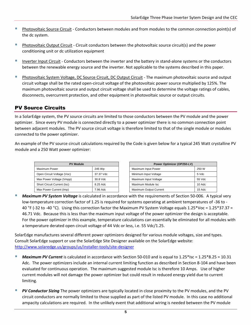
Photovoltaic Source Circuit - Conductors between modules and from modules to the common connection point(s) of
the dc system.
Photovoltaic Output Circuit - Circuit conductors between the photovoltaic source circuit(s) and the power
conditioning unit or dc utilization equipment
Inverter Input Circuit - Conductors between the inverter and the battery in stand-alone systems or the conductors
between the renewable energy source and the inverter. Not applicable to the systems described in this paper.
Photovoltaic System Voltage, DC Source Circuit, DC Output Circuit - The maximum photovoltaic source and output
circuit voltage shall be the rated open-circuit voltage of the photovoltaic power source multiplied by 125%. The
maximum photovoltaic source and output circuit voltage shall be used to determine the voltage ratings of cables,
disconnects, overcurrent protection, and other equipment in photovoltaic source or output circuits.
PV Source Circuits
In a SolarEdge system, the PV source circuits are limited to those conductors between the PV module and the power
optimizer. Since every PV module is connected directly to a power optimizer there is no common connection point
between adjacent modules. The PV source circuit voltage is therefore limited to that of the single module or modules
connected to the power optimizer.
An example of the PV source circuit calculations required by the Code is given below for a typical 245 Watt crystalline PV
module and a 250 Watt power optimizer:
PV Module Power Optimizer (OP250-LV)
Maximum Power 245 Wp Maximum Input Power 250 W
Open Circuit Voltage (Voc) 37.37 Vdc Minimum Input Voltage 5 Vdc
Max Power Voltage (Vmpp) 30.8 Vdc Maximum Input Voltage 55 Vdc
Short Circuit Current (Isc) 8.25 Adc Maximum Module Isc 10 Adc
Max Power Current (Imp) 7.96 Adc Maximum Output Current 15 Adc
Maximum PV System Voltage is calculated in accordance with the requirements of Section 50-006. A typical very
low-temperature correction factor of 1.25 is required for systems operating at ambient temperatures of -36 to -
40 °F (-32 to -40 °C). Using this correction factor the Maximum PV System Voltage equals 1.25*Voc = 1.25*37.37 =
46.71 Vdc. Because this is less than the maximum input voltage of the power optimizer the design is acceptable.
For the power optimizer in this example, temperature calculations can essentially be eliminated for all modules with
a temperature derated open circuit voltage of 44 Vdc or less, i.e. 55 Vdc/1.25.
SolarEdge manufactures several different power optimizers designed for various module voltages, size and types.
Consult SolarEdge support or use the SolarEdge Site Designer available on the SolarEdge website:
http://www.solaredge.us/groups/us/installer-tools/site-designer
Maximum PV Current is calculated in accordance with Section 50-010 and is equal to 1.25*Isc = 1.25*8.25 = 10.31
Adc. The power optimizers include an internal current limiting function as described in Section 8-104 and have been
evaluated for continuous operation. The maximum suggested module Isc is therefore 10 Amps. Use of higher
current modules will not damage the power optimizer but could result in reduced energy yield due to current
limiting.
PV Conductor Sizing The power optimizers are typically located in close proximity to the PV modules, and the PV
circuit conductors are normally limited to those supplied as part of the listed PV module. In this case no additional
ampacity calculations are required. In the unlikely event that additional wiring is needed between the PV module
SolarEdge Three Phase Inverter Sytem Design and the CEC
6
and the power optimizer these conductors should be sized in accordance with Section 50-012. The minimum
recommended temperature de-rated ampacity for these conductors is 10*1.25A = 12.5 A.
Exposed Conductor Types Because the SolarEdge system operates the modules in an ungrounded configuration, all
exposed conductors including any conductors attached to the modules or added by the installer must be listed to UL
Standard 4703 and be labeled PV Cable, PV Wire, Photovoltaic Cable, or Photovoltaic Wire as required by Section 50-
018.
Over Current Devices The SolarEdge power optimizers include automatic reverse current protection which prevents
current from flowing from the inverter input circuit back into the PV module. The majority of SolarEdge systems
may be installed with only two strings. In a two string configuration there are no other parallel connected sources of
fault current between the module and the power optimizers so no overcurrent devices are required in accordance
with Section 50-012 Subrule (1). For systems with three strings or more fuses may need to be installed in both the
positive and negative conductors as required by Section 64-012. For more information refer to the Technical Note
“String Fusing Requirements in SolarEdge Systems” in the following link:
http://www.solaredge.com/files/pdfs/string_fusing_requirements.pdf.
DC Source Circuit and DC Output Circuit (Inverter Input Circuit)
Calculation of the voltage and current in the dc source circuit requires an understanding of the operation of the
SolarEdge system. Traditional PV inverters have MPPT functions built into the inverter. This means the inverter adjusts
its dc input voltage to match that of the PV array connected to it. In this type of system, the modules are wired in series
and the maximum system voltage is calculated in accordance with Section 50-006, using the number of modules in
series, the open circuit voltage of each module and the lowest expected ambient temperature at the system location.
In contrast, the SolarEdge inverters operate with a fixed dc input voltage that is regulated by the inverter. For systems
connected to a 120/208 Vac grid the dc voltage is regulated at approximately +/- 200 Vdc relative to ground. For a
system connected to a 277/480 Vac grid, the inverter regulates the dc voltage at approximately +/- 425 Vdc relative to
ground.
The constant input voltage design of the inverter means that the inverter input circuit current is proportional to the total
array power in accordance with Ohm’s law I=P/V where I is the inverter input current, P is the total array power and V is
the dc input voltage set by the inverter. The relationship between inverter input current and total array power is central
to the operation of the SolarEdge system.
Maximum System Voltage and Voltage to Ground
In the SolarEdge system the PV modules are each connected to a power optimizer. The maximum system voltage would
therefore be limited to that of the individual module, or series connected modules connected to a single power
optimizer. The maximum system voltage would therefore be calculated according to Section 50-006 but only for the
series connected modules feeding the individual power optimizer.
In addition to voltage of the series connected modules feeding the individual power optimizer it is important to evaluate
the module voltage relative to ground. All modules and wiring connected to the input side of the power optimizer
should have a voltage rating based on the greater of:
The temperature corrected open circuit voltage of the series connected modules connected to the individual power
optimizer, or;
The maximum voltage relative to ground during normal operation and during fault conditions

SolarEdge Three Phase Inverter Sytem Design and the CEC
7
Normal Operation
During normal operation the array ground reference is established by the center grounded Wye grid and referenced
through the non-isolated inverter. This equivalent protection prevents over voltages on conductors and equipment and,
results in the ungrounded array voltage being centered equally on either side of ground.
NOTE:
Since the ground reference is established through the inverter, the SolarEdge commercial inverters should not be used with ungrounded
Wye, ungrounded Delta, or corner grounded Delta grid configurations. A separate isolation transformer is required for ungrounded Wye
or for Delta applications. Contact SolarEdge for assistance with ungrounded Wye or with Delta grid configurations
The following examples illustrate the operation of the SolarEdge system with the two most common utility voltages in
the United States; 277/480Vac and 120/208Vac. Each example system consists of (20) 245 W modules with power
optimizers connected in a single string that is connected to a three phase SolarEdge fixed voltage inverter. For the
480Vac system, the dc voltage at the inverter input circuit will be +/- 425 Vdc relative to ground. For the 208Vac system
the dc voltage at the inverter input circuit will be +/- 200 Vdc relative to ground. To simplify the calculations the power
optimizer efficiency is assumed to be 100%.
Example: SolarEdge system operation at 480Vac and at STC
The system consists of (20) 245 W modules used in the previous calculations. Therefore the maximum PV Source Circuit
Voltage is 1.25 * Voc = 1.25* 37.37 = 46.71 Vdc and the PV source circuit design current is equal to 1.25*Isc = 1.25*8.25
= 10.31 Adc. The maximum voltage of the dc circuit to ground is +/- 490 Vdc so all modules and wiring in the PV source
circuit feeding the power optimizers must be rated at least 490 Vdc (typical ratings are no less than 600 Vdc).
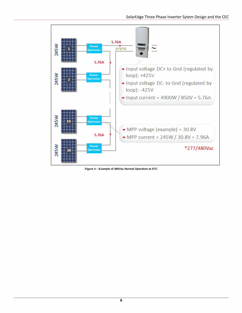
For simplicity we will assume all modules are operating at STC conditions and are producing full rated power. The total
string power is therefore 4900 W (245 W * 20 = 4900 W). Each module is independently MPP tracked by its own power
optimizer and is therefore operating at the STC maximum power point.
The PV source circuit has an operating voltage of 30.8 Vdc (rated max power operating voltage at 25°C), and the source
circuit current is 7.96 A (245 W / 30.8 V = 7.96 A). The dc source circuit (power optimizer output) voltage is regulated at
+/- 425 Vdc (relative to ground) and so the output voltage of the individual power optimizers is 850 Vdc / 20 = 42.5 Vdc.
The maximum voltage of the dc circuit to ground is +/- 490 Vdc so the power optimizers, all wiring and switchgear in the
dc source circuits must be rated for 980 Vdc or more (Note: the SolarEdge power optimizers and the SolarEdge Safety
Switch for three phase inverters are rated for 1000 V; the SolarEdge 277/480 Vac three phase inverters are rated for 980
Vdc). The inverter input current is calculated by Ohm’s law (I=P/V) and is 5.76 A (4900W/850V = 5.76 A). The dc source
circuit design current is 15 Amps continuous which is the output current limit of the power optimizer.
SolarEdge Three Phase Inverter Sytem Design and the CEC
8
Figure 4 – Example of 480Vac Normal Operation at STC
SolarEdge Three Phase Inverter Sytem Design and the CEC
9
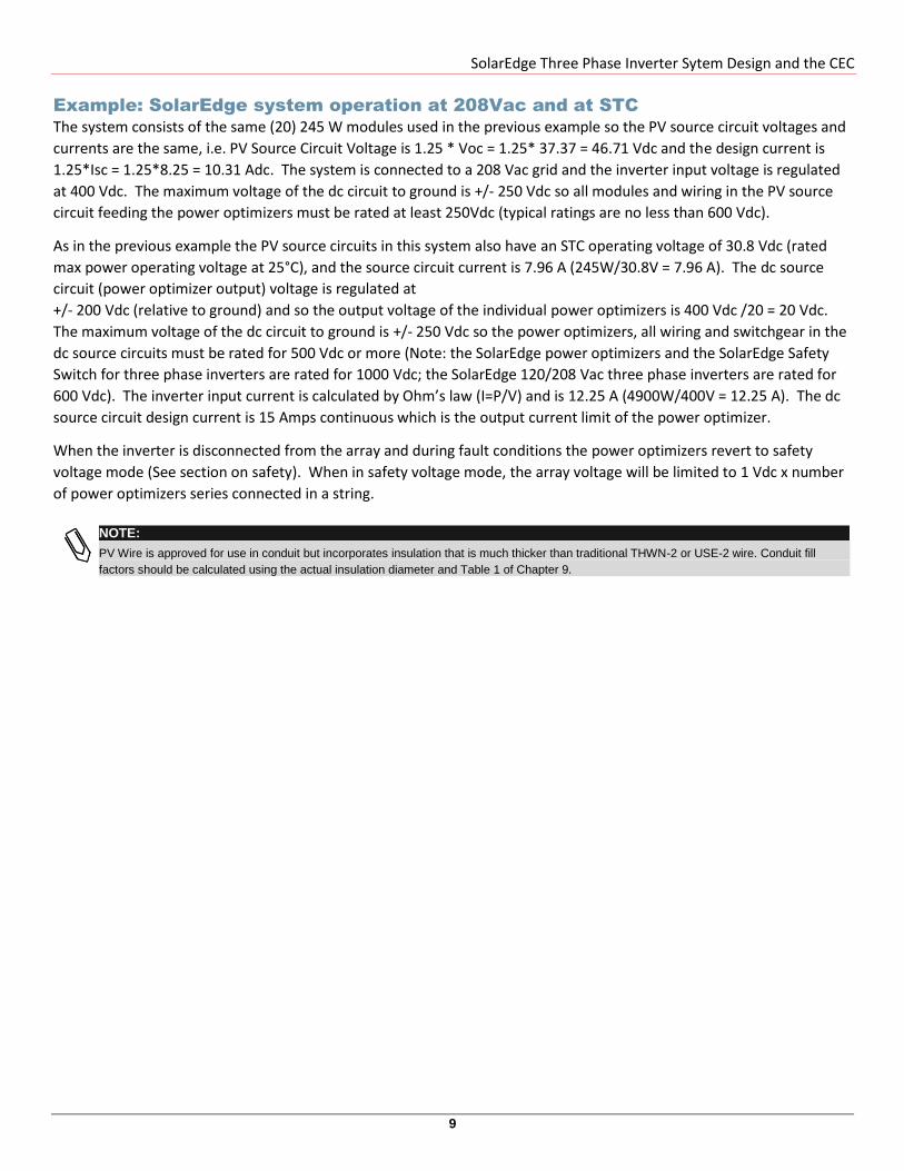
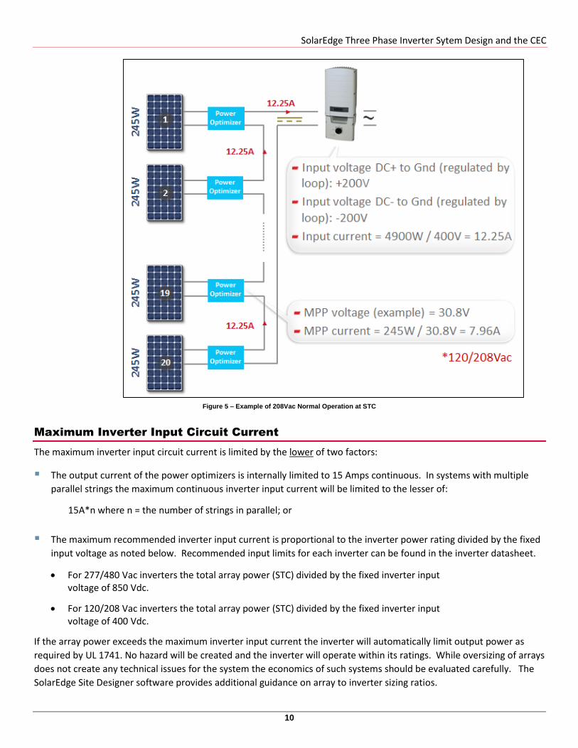
Example: SolarEdge system operation at 208Vac and at STC
The system consists of the same (20) 245 W modules used in the previous example so the PV source circuit voltages and
currents are the same, i.e. PV Source Circuit Voltage is 1.25 * Voc = 1.25* 37.37 = 46.71 Vdc and the design current is
1.25*Isc = 1.25*8.25 = 10.31 Adc. The system is connected to a 208 Vac grid and the inverter input voltage is regulated
at 400 Vdc. The maximum voltage of the dc circuit to ground is +/- 250 Vdc so all modules and wiring in the PV source
circuit feeding the power optimizers must be rated at least 250Vdc (typical ratings are no less than 600 Vdc).
As in the previous example the PV source circuits in this system also have an STC operating voltage of 30.8 Vdc (rated
max power operating voltage at 25°C), and the source circuit current is 7.96 A (245W/30.8V = 7.96 A). The dc source
circuit (power optimizer output) voltage is regulated at
+/- 200 Vdc (relative to ground) and so the output voltage of the individual power optimizers is 400 Vdc /20 = 20 Vdc.
The maximum voltage of the dc circuit to ground is +/- 250 Vdc so the power optimizers, all wiring and switchgear in the
dc source circuits must be rated for 500 Vdc or more (Note: the SolarEdge power optimizers and the SolarEdge Safety
Switch for three phase inverters are rated for 1000 Vdc; the SolarEdge 120/208 Vac three phase inverters are rated for
600 Vdc). The inverter input current is calculated by Ohm’s law (I=P/V) and is 12.25 A (4900W/400V = 12.25 A). The dc
source circuit design current is 15 Amps continuous which is the output current limit of the power optimizer.
When the inverter is disconnected from the array and during fault conditions the power optimizers revert to safety
voltage mode (See section on safety). When in safety voltage mode, the array voltage will be limited to 1 Vdc x number
of power optimizers series connected in a string.
NOTE:
PV Wire is approved for use in conduit but incorporates insulation that is much thicker than traditional THWN-2 or USE-2 wire. Conduit fill
factors should be calculated using the actual insulation diameter and Table 1 of Chapter 9.
SolarEdge Three Phase Inverter Sytem Design and the CEC
10
Figure 5 – Example of 208Vac Normal Operation at STC
Maximum Inverter Input Circuit Current
The maximum inverter input circuit current is limited by the lower of two factors:
The output current of the power optimizers is internally limited to 15 Amps continuous. In systems with multiple
parallel strings the maximum continuous inverter input current will be limited to the lesser of:
15A*n where n = the number of strings in parallel; or
The maximum recommended inverter input current is proportional to the inverter power rating divided by the fixed
input voltage as noted below. Recommended input limits for each inverter can be found in the inverter datasheet.
For 277/480 Vac inverters the total array power (STC) divided by the fixed inverter input voltage of 850 Vdc.
For 120/208 Vac inverters the total array power (STC) divided by the fixed inverter input voltage of 400 Vdc.
If the array power exceeds the maximum inverter input current the inverter will automatically limit output power as
required by UL 1741. No hazard will be created and the inverter will operate within its ratings. While oversizing of arrays
does not create any technical issues for the system the economics of such systems should be evaluated carefully. The
SolarEdge Site Designer software provides additional guidance on array to inverter sizing ratios.
SolarEdge Three Phase Inverter Sytem Design and the CEC
11
Inverter Input Overcurrent Protection and Disconnecting Means
The SolarEdge system has been designed to allow the inverter to operate at full power with a maximum of two strings of
power optimizers in most configurations. The SolarEdge inverter does not allow reverse current flow from the grid back
to the power optimizers during fault conditions. As a result no overcurrent devices are needed between the inverter
and the power optimizers if the PV system is configured with one or two strings of power optimizers.
NOTE:
In some cases three or more strings of power optimizers are wired in parallel. Fusing may be required to protect the wiring between the power
optimizers and the inverter. Because the circuit conductors are not grounded, in such cases fuses would be required on both the negative and
positive conductors. The recommended fuse size of 20 Amps is calculated using the 15 Amp continuous output current limit of the power
optimizer multiplied by 1.25 in accordance with CEC Section 50-012.
For more information refer to the Technical Note “String Fusing Requirements in SolarEdge Systems” in the following link:
http://www.solaredge.com/files/pdfs/string_fusing_requirements.pdf.
The SolarEdge inverter is supplied with a listed combined dc and ac disconnecting means fulfilling all requirements of
Section 50-016. The dc side of the switch disconnects both positive and negative conductors, i.e. all ungrounded
conductors. The dc/ac disconnect includes lockout tagout provisions for enhanced safety of installers and service
personnel.
Safety Features
Ground Fault Protection The SolarEdge system includes ground fault detection as required by Section 64-018
because the array circuit conductors are ungrounded. Each power optimizer monitors its connected modules and
communicates any detected fault to the inverter. The inverter monitors the conductors between the power
optimizers and the inverter. In response to a ground fault the inverter will cease to export power, shut down the
power optimizers to isolate the faulted circuit, and indicate the ground fault on the inverter display. The location of
the ground fault is also flagged in the web-based monitoring software and, optionally, an email notification of the
fault can be generated.
Safety Voltage The SolarEdge system includes a special safety voltage mode that greatly reduces electrocution
hazards for installers and emergency response personnel. During installation and commissioning of the system the
output voltage of each power optimizer is automatically limited to approximately 1 Vdc. Since the maximum
number of power optimizers is limited to 50 or less the maximum safety voltage of the system is limited to
approximately 50 Vdc (277/480 Vac inverters) or 25 Vdc (120/208 Vac inverters).
The inverter input circuit voltage (equal to the sum of all power optimizer output voltages) increases to the normal
operating voltage only when connected to a properly operating inverter. The system automatically reverts to safety
voltage mode, i.e. 1 Vdc per power optimizer, should the inverter experience any fault condition, be disconnected
from the grid, or if the power optimizers are disconnected from the inverter.
Grounding
The SolarEdge system utilizes ungrounded PV arrays as allowed under CEC Section 64-018. Because the array is
ungrounded, the requirements of Section 64-020 are not applicable and no main system bonding conductors or dc
grounding electrode conductors are required. The inverter and power optimizers must each be supplied only with an
equipment ground as required by Section 64-022. The equipment grounding conductors should be sized and installed in
accordance with the requirements of Sections 10-808 and 10-814 and Table 16.
Power Optimizers Where the output of the power optimizers is protected by an over current device, the array
equipment grounding conductors should be sized based on the size of the overcurrent device. Since no over current
protective devices are required in a typical SolarEdge system, the equipment grounding conductors should be sized

SolarEdge Three Phase Inverter Sytem Design and the CEC
12
based on the maximum power optimizer output current of 15 Amps. Table 16 would yield a minimum equipment
grounding conductor size of 14 AWG copper, but may require a larger size.
Equipment grounding of power optimizers can be accomplished using one of two methods as outlined in the SolarEdge
installation manual:
1 Power optimizers are typically bolted directly to a metallic support structure and can be grounded
through that support structure using stainless steel star washers between the power optimizer and
the support structure. The star washers supplied with the power optimizers have been evaluated
and listed as a grounding means in accordance with the requirements of Section 64-022.
2 When mounted to metallic structures using sliding nuts, or to non-metallic structures, a separate
equipment grounding conductor is required. Optional supplementary grounding hardware is
available for this purpose. Contact SolarEdge for details.
Inverters The ac output equipment grounding conductor for the inverter is required in accordance with Table 16.
The size of the equipment grounding conductor is based on the size of the ac overcurrent device protecting the ac
output circuit connected to the inverter. The minimum allowable size of the ac overcurrent device should be sized
based on the continuous output current of the inverter * 1.25. The maximum size of the ac overcurrent device for
each inverter is specified in the inverter documentation.
For additional information concerning the installation of SolarEdge equipment please refer to the installation manuals
and white papers supplied with the equipment or on the SolarEdge website www.solaredge.com.