
Solar Evaporation Ponds at the Salton Sea for Salinity Control

, . . , ,
S O L A R SEA PO WE^ . , P,LANTS , . I
( S S P P ) . ' _ I , . . . . , .
~. f . . , , .
, ,
A c r i t i c 6 1 ., . R e v i e w a.nd s u r v e y , .
-. . - ~ .~~ .. .. .. .~ . . - . . . A - . - . . . - . - ' (NASA-TFi-X-70783) SOLAR SEA POWER PLANTS N 7 5 - 11459
(SSPP) : . A C ~ I T I C A L R E V I E W A M S S U R V E Y (NASA) ' CSCL 1 0 A
U n c l a s G3/44 02696 - ,~ , - - ~- I , .
, . . .
- .. - . . .- - - - . . .,
Bsp,od"red by
NATIONAL TECHNICAL lNFORMATlON SERVICE
U S ~ ~ ~ ~ n ~ a n t 01 Comm-re* S P , ; ~ . I ~ ~ I ~ . VA. 12151 ~ .. -
. . . ~ . .
- GODDARD SPACE FLIGHT CENTER GREENBELT, MARYLAND

"This paper presents the views of the author(s), and does not necessarily re- flect the views of the Goddard Space Flight Center, or NASA."
For information mnaerning availability of Ulis document mntacl:
Technical Information Division, Code 250 Coddard Space Night Center Greenbelt, Maryland 20771
(Telephone 301-982-4488)

SOLAR SEA POWER PLANTS (SSPP)
i\ Cri t ica l Keview and Survey
Alvin M. S t r a u s s 1)epartmenl of Engineering Analysis
University of Cincinnati Cincinnati . Ohio 45221
S e p t e m b e r 1974
T o b e p r e s e n t e d a t I n t e r n a t i o n a l So l a r E n e r g y S o c i e t y
I n t e r n a t i o n a l C o n f e r e n c e U n i v e r s i t y o f C a l i f o r n i a , L . A .
L o s A n g c l e s , C a l i f o r n i a J u l y 1 9 7 5
T o be p u b l i s h e d i n So la r E n e r g y - T h e J o u r n a l o f
S o l a r E n e r g y S c i e n c e & T e c h n o l o g y
GODDAJtI) SPACE FLIGHT CESTER Green l~c l t . Mal.ylulld

Frontispiece

CONTENTS
IV . V .
VI . VII .
VIII .
INTRODUCTION . . . . . . . . . . . . . . . . . . . . . . THE ENERGY PROBLEM . . . . . . . . . . . . . . . . . THE SOLAR SEA POWER PLANT (SSPP):
AN OVERVIEW AND ECONOMICS . . . . . . . . . . . MARICULTURE AND SITING . . . . . . . . . . . . . . . MATE RIALS . . . . . . . . . . . . . . . . . . . . . . . THE XITINOL ALTERNATIVE . . . . . . . . . . . . . . . THE S S P P A S D THE CLAUDE CYCLE . . . . . . . . . . . TIIE CLOSED CYCLE S S P P . . . . . . . . . . . . . . . . A . Heat Exchangers . . . . . . . . . . . . . . . . . . . . B . Worlting Fluids . . . . . . . . . . . . . . . . . . . .
. . . . . . . . . . . . . . . . . . . . . . . C . Turb ines D . Cold Wate r Supply and P i p e . . . . . . . . . . . . . . . E . Mooring and Anchoring . . . . . . . . . . . . . . . . .
. . . . . . . . . . . . . . . . . . . . F . I-Iumnn F a c t o r s
COMPI. E MEKTARY AKD AUGhlESTEU SSPP EXERGY SYSTEM . . . . . . . . . . . . . . . . . . .
The Energy Shol-tagc . . . . . . . . . . . . . . . . . . The Pollution P r o b l e n ~ . . . . . . . . . . . . . . . . .
. . . . . . . . . . . . . . . . . . . . . . . . . Cost . . . . . . . . . . . . . . . . . . . . . . Maricul ture
Siting . . . . . . . . . . . . . . . . . . . . . . . . . Law . . . . . . . . . . . . . . . . . . . . . . . . . Mater ia ls . . . . . . . . . . . . . . . . . . . . . . .
. . . . . . . . . . . . . . . . . . . T h e Sitiilol S S P P The Claude CJ-clc SSPP . . . . . . . . . . . . . . . . . The Closed Cycle S S P P . . . . . . . . . . . . . . . . .
. . . . . . . . . . . . . . . . . . . . \\'orking Fluids L . Turb ines . . . . . . . . . . . . . . . . . . . . . . . n.1. c o l d \ ~ : t t c r . . . . . . . . . . . . . . . . . . . . . .
. . . . . . . . . . . . . . . . . . Mooring : l i d Anchoring . . . . . . . . . . . . . . . . . . . . . . . O L m d o r S e a
. . . . . . . . . . . . . . . . . . . . . P Humnn F a c t o r s . . . . . . Q . Complementary :uid Augmented' Energy Systcnls

ILLUSTRATIONS
Figure - 1
2
3
4
5
6
7
Page
World Energy Consumption Since 1960 . . . . . . . . . . . 3
World Energy Needs Since 1960 . . . . . . . . . . . . . . 3
Closed Cycles SSPP. . . . . . . . . . . . . . . . . . . . 11
Schematic of the UMASS Design . . . . . . . . . . . . . . 12
Solar Sea Power Plant (100 MN') Schematic . . . . . . . . . 13
Flowchart for Alternative Ocean Thermal Gradient Systems . . 1 6
Schematic of Open Cycle Variant of Ocean Thermal Gradient Collection and Conversion . . . . . . . . . . . 17
Plan of the 1500 KW Experimental SSPP . . . . . . . . . . . 19
Monthly Variation of Sea-surface Temperature in Japan and Tropics . . . . . . . . . . . . . . . . . . . 23
Annual Cycle of Monthly Average Surlaee Temperature. Bottom Temperature, Surface Salinlty . and Computed Surface S o u ~ ~ d Velocity at Five L~ghtshlp and Lighthouses and f o r a I ' Square of Mlaml A r e a . . . . . . . . . . . . 24
Polygons Showing Monthly Average Salinities and Temperatures for 1956-G1 . . . . . . . . . . . . . . . 25
Surface Temperature of Western North Atlantic Ocean During February . . . . . . . . . . . . . . . . . . . . 26
Surface Temperature of Western n'orth Atlautic Oceail During August . . . . . . . . . . . . . . . . . . . . . 27
Average Annual Variation of 'Temperature 'and Salinity at Depth In F ~ v e Selected Areas on Atlantic Continental Shelf. . . . . . . . . . . . . . . . . . . . 28
The Sitinol Deformation-Memory Process . . . . . . . . . . 33
Shnpe Rccover!; Fatigue Curve lor 0.020 in. Diameter Xitinol Wire . . . . . . . . . . . . . . . . . . . . . . 33
Schcinatic Diagram Illustrating the Conversion o l Heat Energy to Mechanical Energy Using 55-Nitinol . . . . . . 31
LTivlASS Heat Exchanger Study Resul ts . . . . . . . . . . . . 40
Influence of Surface Treatment on Saturated Pool Boiling . . . 42

ILLIJSTRATIONS (continued)
Figure .
2 0
2 1
22
Table .
1
. Simple Cylindrical Heat Pipe . . . . . . . . . . . . . . . 43
The Working Range of a Heat Pipe . . . . . . . . . . . . . 44
Diagram of the Measured Maximum Hcat Flux q for Various Working Fluids. and the Temperature at whlch these a r e Ordinarily Used . . . . . . . . . . . . . . . . . . 45
SSPP Complemented and Augmented Energy System Schematic . . . . . . . . . . . . . . . . . . . . . . . 53
Typical Systcms Location . . . . . . . . . . . . . . . . . 54
A Model Marine Industrial Complex . . . . . . . . . . . . 55
. . . . . . . . . . . A Plan of Ocean Pumped Storage Plant 56
. . . . . . . . . Types of Steam-Electric Generating Plants 57
Map of the Hawaiian Islands with Locations of Possible Floating City Sites . . . . . . . . . . . . . . . . . . . 58
. . . . . . . The Claude Ocean Thermal Difference Process 61
TABLES
Comparison of Cost of Electricity for Various Types of Systcms . . . . . . . . . . . . . . . . . . .
Prel iminary Cost Estimate lor the SSPP . . . . . . . . . . . . . . . . . . . . . . Cost of Electric Power at SSPP Plant
100MW SSPP . . . . . . . . . . . . . . . . . . . . . . . . . . . . . Specification of the Experimental 150Okw SSPP
Rough Estimation of the Cost of Experimental . . . . . . . . . . . . . . . . . . . . . 1500kw SSPP
Dependency of Power Output to Cold Water Temperature . . Evaluation of SSPPs Using Various Working Fluids . . . . . .
. . . . Comparison of Working Fluids for Ideal lOOmm Cycle
Optimum Parametcrs for Turbines with Ammonia and Propane a s Working Fluids . . . . . . . . . . . . . . .
Page

SOLAR SEA POWER PLANTS (SSPP)
A Critical Review and Survey
I. INTRODUCTION
This report i s a critical survey of the SSPP concepts considered relevant and important to the eventual success o r failure of the SSPP itself. It i s a result of a 10 week study of the SSPP. As a consequence of the amount of time spent on this survey, there will be gaps in the li terature quoted and certain concepts that a r e not gone into in the detail that i s commensurate with their importance. The author is solely responsible fo r the content of this report and any inaccuracies are probably due to him. Also, al l recommendations a r e his alone and were evolved after some periods of short but intensive thought.
In a manner of speaking this entire report i s an extended introduction to the SSPP itself, its economics, alternatives, prohlems and contradictions.
The author would like to acknowledge his gratitude to those who have assisted him in the preparation of this report. Special thanks are due to Tom Golden for getting the author interested in the SSPP project and for having' a certain degree of confidence in him. The author thanks Bill Cherry for being his colleague and acknowledges the fact that without the long and detailed discussions he had with Jack Peake this ?eport would not have attained i ts final form. The author would also like to thank the rest of Code 704; Elaine Robbitt for explaining some intri- cacies of the system. Special thanks go to D r . Robert Cohen of the National Science Foundation who the author relied on a s the SSPP expcrt and through whom the author was put in contact with various SSPP researchers.
Finally, this report relates to the present state-of-the-art and the building of demonstration plants and not t o the eventical massive build up of ocean-based SSPPs. It is crucial tha tany demonstration projects he very successful i l the SSPP concept i s to grow and eventually succeed in producing significant amoulits of energy, and it is to the demonstration aspects of SSPP design that this report addresses itself.
LI. THE EX'ERGY PROBLEM
The problems associated with hoth the availability of adequate supplies of ener- gy, to meet the needs of the individual and industry: and the unavailability of adequate energj- resources to meet demand have been adequately and incessantly voiced UI the technical literatul-e, popular magazines 2nd daily newsp:ipers. It

therefore appears to be sufficient to review only a few general idcas that may have direct bearing on Solar Sea Power Plant (SSPP) concepts.
In view of the changes in attitude that have taken place due to the energy short- age and the consequential pr ice increases for energy, most of the predictions made concerning future energy use , both in t-ype and magnitude; will have to he revised. This is especially t rue of the all too common exponential growth curves and the equally inaccurate linear extrapolation models. It appears clear that we will be using more energy by the year 2000. However, the sources of that en- ergy (coal, so lar , wind, oil , geothermal, nuclear, hydroelectric. etc. ) cannot be predictcd with any assurance beyond a 20 year interval.
One consequence of this is that without the long range integrated planning of the total energy resource and use system the American people will experience a serious deterioration in the quality of their environment. This will be most serious in two areas :
(a) The east coast urbanized a r e a which extends in almost a straight line from the s ta r t of this megalopolis north of Boston to its termination south of Washington. D. C. This a r e a includes the cities of Baltimore, Philadelphia, New York: Providence, Hartford, Newark: Wilmington, etc .
(b) The second area is the Great Lakes region and includes those cities bordering on the Great Lakes such a s Buffalo, Cleveland, Toledo. De- t ro i t , Chicago, Milwaukee, etc.
There a r e other populous regions with problems such as Southern California, the Gulf Coast, the Ohio Valley and the Mississippi. but the most serious prob- lems will a r i se in the former two a reas .
In any case all the a reas mentioned a r e liliely to have significant populatioe in- c reases over the coming decades and it is likely that their ui-banizcd a reas will increase significantly. In addition, more large electric power generating facil- i t ies. heavy industry and manufacturing si tes will likely be constructed in and around these population concentrations. One must also consider that the num- be r of road vehicles will increase in proportion to the population and the various automobile and truck problems will be magnified in time. 1
According to the best estimates available, the pollution problems in our urban areas will not be solved before the year 1995. With respect to crude oil it is reasonable to expect the earth's supply will be essentially depleted in approxi- mately 100 ycars due mainly to the growth in the world's yearly energy con- ~ u m p t i o n . ~ Figures 1 and 2 (from Ref. 2) graphically illustrate the overall ten- dency of greatly increasing worldwide energy consumption. These curves a r e likely to be accurate because of the steady industrialization of previously under- developed nations.

Figure 1. World Energy Con- sumption Since 1960. Curve A
measures the energy use pe r capita per year; Curve B , the
total energy consumed per year .
Time, years A D .
Figure 2 . World Energy Needs Since 1960. Curve A measures total energy consumption, and
Curve B indicates the cumulative energy use.
Time, years A.0.

From the data indicating ever increasing numbers for the earth's fossil fuel re- serves, we will doubtless still be dependent on fossil fuels for the major portion of our electric power in the year 2000 and for some time thereafter. Therefore we will have to contend with both thermal and chemical pollution until that time. By the year 2000 the U.S. may well be environmentally cleaner, but the world will be a much dirtier plnce (see FiguFes 1 zrjv 2). For cxzimple, a 3,000MW oil burning power plant, using crude oil with a 3% sulfur content, will produce daily: 700 tons of sulfur oxides, 180 tons of nitrogen oxides, 6 tons of soot and - other particulates and 5.4 tons of various hydrocarbons. And now with increas- ing prices for oil the power industry's claim that pollution control devices a r e uneconomical take on noteworthy environmental importance. The average citi- zen is for the most part unwilling to pay for pollution control in addition to the present relatively high energy prices. Also, pollution control devices can use up to 10% of the power being produced by a power plant. This is not only uneco- nomical, but adds to existing power shortages, Also, no pollution control device is 100% effective and even with massive multibillion dollar efforts there will al- ways be a pollution problem in heavily populated areas.
The thermal pollution problem is also serious. A typical large electric power plant will reject 60% or more of its total heat to the environment. Thus if 3,000 MWel,,, a r e produced in a fossil fuel power plant, about 4,500 MWt~iem>al will be rejected to the environment, i .e . , 3,800 MWtherlnal via the cooling fluid and 700 MWtllerlllal via the chimney gases. Thermal pollution problems are not well understood at this time; especially the environmental effects over long pe- riods of time.
These facts alone (aside from political and other consideration) would warrant a closer look at the SSPP. But first let us consider another alternative; nuclcar power. There a r e now approximately 290 nuclear power reactors operating in approximately 25 nations. By the year 2000 the equivalent of one new 1,000 MW,leCt nuclear plant wi l l be brought into action each day .3 One great ad- vantage of a nuclear power plant is that it will not produce any chemical or par- ticulate pollutants. However, thermal pollution poses a greater problem in nlu- clear power plants. If our 3,000 MW,1,,, fossil fuel plant was a nuclear power plant it would reject 5,600 MW,t,,,,,l to its cooling fluid, or about 50% more than the fossil fueled plant. This is not the only problem, however. Nuclear power plants will in the long run emit small amounts of long lifetime radioactive ma- terial. As power production expands the background radiation levels will grad- ually rise in the power plant's vicinity. Krypton-85, radon and tritium gases a r e normally produced in the course of the normal reactor cycle. Other iso- topes are either stored o r released into the cooling fluid (lake o r ocean) at low concentration where they may be concentrated in food chains.

The only thing that need be said about the radioactive waste disposal problem is that a final solution has not, as of yet, been proposed. Disposal remains a very serious problem that must be solved before we become significantly dependent upon nuclear power.
The greatest drawback, real and psychological, possessed by nuclear power is its catastrophic potential. After the fuel elements of a 1,000 MW,l,,, power plant have been in operation for one year the fissionable material produced in the sheathing of the fuel elements is equivalent to that produced by a 50 megaton fission bomb.4 Thus an accident rupturing the fuel sheaths could send millions of curies of harmful radiation into the local environment.
An even greater potential problem is the possibility of a loss-of-coolant catas- t r ~ ~ h e . ~ Without getting into details, this would scatter massive amounts of radioactive material into the atmosphere which could be lethal for dozens and under some conditions up to 100 miles. If this occurred in any of our great pop- ulation centers such as the east coast or Great Lakes regions millions could perish.
With all this in mind let us consider anattractive alternative to producing power: the SSPP. Wb.ile the SSPP will not be the answer to the nation's energy problems, it may nontheless play an important role in reducing these problems. Ocean thermal energy is an inexhaustible resource for as long as the sun shines and of- fers the possibility (as will be described below) of providing food (mariculture) and fresh water (desalination) as byproducts.
111. THE SOLAR SEA POWER PLANT (SSPP): AN OVERVIEW AND ECONOMICS
In 1881 Jaques d1Arsonval published his thoughts on the possibility of construct- ing a steam power generator that made use of the temperature difference between the surface water and the deep water in thc tropical seas.6 in 1930 Georges Claude actually constructed this type of SSPP at Matanzas Bay, ~ u b a . ~ This plant had a 22KWe~,,, output. This experimental SSPP operated by taking advan- tage of a 14'C thermal gradient. The cold water was brought up from 700 me- ters below the sea surface in a 1.6 meter diameter pipe which extended to 2 km offshore.
In the 1950's a French corporation, Energie Electrique de la Cote d'lvoire, planned the construction of an SSPP at Abidjan Ivory Coast. This plant was never put into operation, contrary to the report in Reference 8. This SSPP was to have produced steam power based on a 20" thermal gradient. The cold wa- ter would have been brought up from a depth of 430 m . 4 knl offshore and pumped

through a 2 m diameter pipe. The flow through the cold water pipe was designed to operate at 2 m/sec. However, approximately 25% of the power produced by this SSPP would have been consumed by the operations of the SSPP itself.
Ocean thermal gradient power production! along with wind power generation will become increasingly attractive, =,nc! even necessary, a s we tiijiji*oach the 21st century. Thus, there will be great demand for fossil fuels, but not neces- sar i ly for the purposes of power generation, Oil, coal and natural gas will be needed by the various chemical industries for the production of lubricants, paints, plastics, synthetic products, food, and fertil izer. 9
The comparative attractiveness of the SSPP a s opposed to other solar energy schemes (even without considering desalination and mariculture) is due to cost. The SSPP does not need acres of expensive solar collectors o r expensive storage units for nights and cloudy days. The ocean continuously ac ts a s a collector and a s a heat storage unit. SSPPs a r e also economically attractive when compared to conventional fossil fuel and nuclear power plants. The Andersons estimate that a SSPP can be constructed for $200 per kilowatt.1° New nuclear powered plants cost $700 pe r kilowatt and new coal fired plants cost more than $550 per kilowatt. In addition the fuel costs for fossil and nuclear plants a r e rapidly in- creasing (SSPP fuel i s free) and should be taken into consideration. Table 1 gives some cost details for comparative power systems. 11
Ocean thermal gradient power production has the potential for supplying 100% of the U.S. electr ic energy requirements in the not too distant future. By the year 2000 it could supply up to 5% of those requirements, and by the year 2020, 10% o r more. To get some idea of the magnitude of the energy available consider that in 15 minutes the earth intercepts enough radiant energy from the sun to equal the amount of energy that i s consumed worldwide in the form of fossil and nuclear fuels each day. In less than four days, an amount of energy equal to all of the earth 's fossil fuel reserves i s intercepted. - There a r e two distinct SSPP types with respect to siteselectionr the shors- based system and the ocean-based system. The typical shore-based system would be located on the coast lines of Florida, Puerto Rico: Hawaii, etc. How- ever , the availability of suitable coastline constrains the g ross quantity of pou7er that shore-based systems can generate. Ocean-based systems will typically be constructed so a s to be a self contained floating o r tethered platform submerged below the surface of the sea , but still above the thermocline. The optimum lo- cation for such a plant is in tropical waters , 23"N t o 23"s." Transmission and storage problems may limit the amount of power delivered by ocean-based plants. For example, if SSPPs were to supply 10% of the U.S. energy require- ments by the year 2020, about 0.3 million tons of hydrogen would have to be shipped each day. That is the equivalent of 30 shiploads pe r day where each

Table 1
Comparison of Cost of Electricity for Various Types of Systems (In terms of estimated dollar values for period indicated)
Hydro-Electric 1 (With H z 0 S t o w e ) ~ zl Gar-Fired
Type of System
- $392 to' $1230/kw
Orgonis Mat.-Fired
Solor-Thermal (Without Storage)
Soior- Thermal (With Thermal Storage)
Ocean AT (Without Storage)
ln i t io l investment, Power Generotion
Oil-Fired
Gal -F i red
Nusleor-Fueled
Wind Energy w i thou t Storage; to to
o r with H,O Storage) s346fiw $341/kw
1980 I941
Wind Energy $173 to $195 to (With H, Storage) $346/kw $3W/kw
2W0
Fuel cost55
$323/kw1
$313/kw2
$396/kw3
Photovoltaic 1 PIIS Wind Energy I $937 1 to (With H, $1023/kw $51 l/kw
1580 to 2WO
lnit iol lnvertment. Conversion 8 Storage
$364/kw1
$352/kw2
$447/kw3
1941 to 2010 1580
Other Costs
2000 to 2020
1980 to 2000
$458/kw1
$442/kw2
$56Q/kw3
I990 20W 19W to 2010
$l443/kw
$955/kw
P328/kw6
2WO to 2020
$2132/kw
$i443/kw
5412/kw6
$2451/kw
$l666/kw
$412/kw6
1
- - -
- - $1207/kw7
$1 174/kw7
$1698/kws
- $1517/kw7
81475/kw7
$21 34/kw8
- $1517/kd
$1475/hv7
$2134/1m8 - 1 -

Table 1 (continued)
Average Price of Electricity at Plant
Type of System
Hydro-Electric 1 $1049 to 1 $1282 to 1 $1362 to / 0.60 1 0,60 1 O,Ml 1 I O d k w h to / 12m/kwh to I 13m/kwh to / (With H z 0 Storage) $2988/kw $3M3/kw $3891/kw 28 m/kwh 35ny'kwh 37 d k w h
Gas-Fired i $ 2 8 1 2 / k w k W / $4166/kw 0.60 / 0.60 1 0.60 i 2 7 d k w h i 36m/kwh
Organic Mot.-Fired $1487 to $1827 to $1917 to 1 O,Ml 1 0,60 1 O,Ml / 14ny'kwh to 17m/kwh to I 18m/kwh to I I $2775/kw I $3449/kw 1 $3539/kw 26 m/kwh 33 m/kwh 34 m/kwh
Oil-Fired 7";": Cool-Fired $2442/kw $3260/kw $3583/kw
Nucleor-Fueled $2442/kw $2993/kw $3 106/kw
(Without Storoge) $3515/kw $3360/kw $2420/kw 0.25 0.25 0.25 80 ny'kwh 7 7 d k w h 55ny'kwh -
(With Thermal Storage) $4509/kw $4577/kw $3703/kw 0.25 0.25 0.25 103m/kwh 104ny'kwh 8 4 d k w h
(Without Storoge)
Wind Energy (Without Storage; 31 ny'kwh 38 m/kwh 4 0 d k w h
0.60
0.60
0.60
Wind Energy $2367 to $2908 to $3058 $0 0.30 0.30 0.30 4 5 d k w h to 5 5 d k w h to (With H, Storage) $3108/kw $3816/kw $4016/kw 5 9 d k w h 72m/kwh 7 6 d k w h I 1
(Without Storage) $7373/kw $3048/kw $151 2/kw 0.25 0.25 0.25 168m/kwh 69 d k w h 34m/kwh --
(With H 2 Storage) $8367/kw $4266/kw $2796/kw 0.25 0.25 0.25 190m/kwh 97 m/kw h
Plus Wind Energy 92 m/kwh to 5 0 d k w h to i$g)rW ]iiG/kOw 0.275 0.275 0.275 llOm/hrh 60 d k w h 45 d k w h (With HI Storoge)
42 d k w h
34ny'kwh
28 m/kwh 30 m/kwh
A I 0.60
0.60
0.60
0.60
0.60
0.60
28 d k w h
23m/kwh
23m/kwh
Footnotes for Table 1
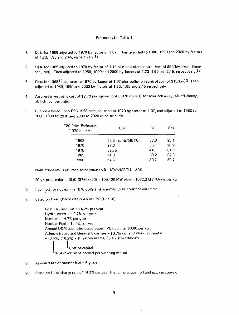
Data for 1968 adjusted to 1970 by factor of 1.07. Then adjusted to 1980, 1990 and 2000 by factors of 1.73. 1.95 and 2.45, respectively.l2
Data for 1965 adjusted to 1970 by factor of 1.14 plus pollution control cost of $56/kw (from Simp- son, ibid). Then adjusted to 1980, 1990 and 2000 by factors of 1.73, 1.95 and 2.45, respectively.13
Data for 196812 adjusted to 1970 by factor of 1.07 plus pollution control cost of $151kw!~ Then adjusted to 1980, 1990 and 2000 by factors of 1.73, 1.95 and 2.45 respectively.
Assumes investment cost of $2.70 per square foot (1970 dollars) for solar cell array; 4% efficiency. x5 light concentration.
Fuel cost based upon FPC 1968 data. adjusted to 1970 by factor of 1.07. and adjusted to 1980 to
2000, 1990 to 2010 and 2000 to 2020 using scenario.
FPC Price Estimates 11970 dollars)
Coal Oil Gas
Plant efficienty is assumed to be equal to 0.1 MWhIMBTU = 30%
20 yr. production = (0.6) (8760) (20) = 105.120 MWhikw = 1072.2 MBTUIkw per kw
Fuel cost for nuclear ( in 1970 dollars) is assumed to be constant over time
Based on fixed charge rate given in FPC (1-19-6)
Coal, Oil, and Gas = 14.2% per year Hydro-electric = 9.7% per year Nuclear = 14.7% per year Nuclear Fuel = 12.4% per year Annual O&M cost rates based upon FPC data, i.e. $3.00 per kw: Administrative and General Expenses = $075/kw: and Working Capital = (3.4%) (10.2%) x (Investment) = 0.35% x (Investment)
t !cost of capital % o f investment needed per worktng capital
Assumed life of nuclear fuel = 5 years.
Based on fixed charge rate of 14.2% per year ( i .c same as coal, oil and gas, see above)

ship carries 10,000 tons of hydrogen per trip. Underwater hydrogen pipelines might be feasible, or direct dc electric current transmission with dc to ac con- verters on shore, may be the most economical solution to the energy transpor- tation problem.
i r l ariciiiioll io i'nt: silore-based, ocean-based controversy, there are many dif- ferent points of view regarding whether to build a closed cycle or an open cycle SSPP, and if a closed cycle SSPP is built what is to be the working fluid. Fig- ures 3 and 4 (from Ref. 14) show one version of a closed cycle SSPP. Figure 5, along with Tables 2 and 3, give yet another design and cost estimates for a closed cycle SSPP.15 Another version of the closed cycle SSPP is shown in Fig- ure 6.11 An open cycle system is illustrated "1 Figure 7.11 This is essentially the system designed by Claude around 1925.7
At this point it is worthwhile to describe the NSF supported designsfor theSSPP. The first SSPP design we will explore is the well known Zener concept. Zener has been very effective in popularizing his ideas in the popular scientific litera- ture.l69l7 The Zener, or Carnegie-Mellon University (CMU)SSPP is a 1 0 0 meg- awatt plant.18 The cold water pipe for this plant will be 2000 feet long and 60 feet in diameter and bring 10 million gallons per minute up to the SSPP conden- sers . The CMUplan also calls for 8 ft/sec water flow through the heat exchanger tubes. These tubes will be l o f t long and one inch in diameter.
The thermal gradient that will operate this SSPP is assumed to be 20'C of which 10"Cwill be dissipated inforcing the heat to the working fluid. This leaves 10°C available for the heat engine and yields an efficiencyof abitover 2%. The weight of the tethering cable is estimated to be 800,000 lbs. Table 4 compares the cost of the CMU SSPP with the Anderson concept referred to above. The life of the CMU SSPP is assumed to be 25 years with maintenance and the heat exchangers are assumed to be the life limiting components. Further details of the CMU SSPP may be found in Reference 19. The details of the CMU design remain rather sparse. The work thus far generated has concentrated on somewhat narrow prnhleme th9.t hhav~ heen gone into in greltt dctai!. Whzt is iieede: by the CMU team is an integrated system design of their SSPP to at least obtain a preliminary configuration and some details of the interfacings of the various subsystems. With this accomplished a trade-off analysis can be performed to optimize subsystems and components.
The other proposed SSPP design is due to W. Heronemus and his group at the University of Massachusetts (UMASS). A schematic of the UMASS design is shown in Figure 4. The UMASS SSPP is designed to be placed in the Gulf Stream 15 miles east of the Collier Building of the University of Miami. The UMASS system assumes a thermal working gradient of 31.5"F and an efficiency of 1.8%. Propane is to be the working fluid for this 400 megawatt SSPP. The cold water
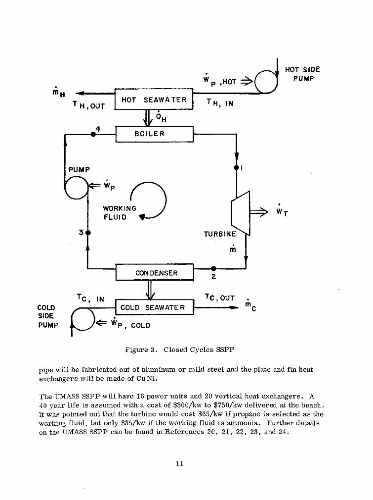
Figure 3 . Closed Cycles SSPP
pipe will be fabricated out of aluminum or mild steel and the plate and fin heat exchangers will be madc of Cu Ni.
The UMASS SSPP will have 16 power units and 20 vertical heat exchangers. A 40 year life is assumed with a cost of $300/kw to $750/kw delivered at the beach. It was pointed out that the turbine would cost $65/kw if propane is selected as the working fluid, but only $35/kw if the working fluid is ammonia. Further details on the UMASS SSPP can be found in References 20, 21, 22, 23, and 24.

MAJOR - - COMPONENTS
narbolrd prerwre hull
wafer inlet hinge ioint
scale: 1 in. = 120 f l
Figure 4. Schematic of the UMASS Design

WATER IN 4 I a F
Figure 5. Solar Sea Power Plant (100 MW) Schematic

Table 2
Preliminary Cost Estimate for the SSPP
I Working Medium I ~mrnonia I
Ethylene Propane I 1 Oxide
Component
Boiler
Boiler feed tube
Boiler water collector tube
Condenser
Condenser exit water deflector
Condenser cold water pipe I I I
Turbine generator 1 2.8 1 6.5 1 20.1
Cost (Millions of dollars)
Turbine piping I I I
4.2
0.01
0.4
7.5
0.2
3 .4
Working medium
Miscellaneous piping and auxiliary items (lO%sr,)
0.02
Liquid pumps
Platform
4.3
0.01
0.4
13.8
0.2
3.2
0.24
4.3
0.01
0.3
10.6
0.2
2 .9
0.03
1.0
5.0
TOTAL
Net power output* (MW)
Plant cost per 100MW (millions of dollars)
0.03
0.20
-
$27.3 M
92.3
29.6
0.39
1 . 2
5.1
!Rankine cycle net power (1 00 MW) mlnus pumplng power.
1.1
5.1

The design of a land-based system i s not as complex as that of an ocean-based system and both the CMU and UMASS SSPP concepts can be applied to land- based systems with little redesign of the working components. In fact, we have had a lot more experience with land-based piping systems that a re applicable to SSPP design. The Ivory Coast pipeline was designed to be 4 miles long; there a r e many sewer outfall pipes longer than 4 miles made out of concrete. On Cyprus there is a 2 mile long plastic waste water pipe that was installed by un- +eeling the pipe and simply anchoring it to the sea floor.
Cost of Electric Power at SSPP Plant
The Japanese a re also interested in the design of an ocean based S S P P . ~ ~ Shown in Figure 8 is a preliminary conceptual design for a 1,500 KWelect SSPP. The specifications for the SSPP a r e shown in Table 5 for two working fluids. The cost data for this SSPP with respect to these working fluids is shown in Table 6.
Construction Cost, lOOMW Plants
Initial cost ($M)
Amortized cost, 25 y r @ 8% ($M)
Amortized cost ($/kw)
Amortized cost (mill/kwh)
Insurance (1% of initial cost , mill/kwh)
Subtotal, fixed cost at 100% capacity (mill/kwh)
Operating costs: 30 men at* $33 K/m-hr (millhwh)
Total cost (mill.kwh)
'Arbitrary cstimale - may he iliglr.
Ammonia
29.6
68.5
685.0
3 .1
0 .3
3.4
1 .2
4.6
Propane
45.1
104.3
1043.0
4.8
0.5
5.3
1 .2
6 . 5
Ethylene Oxide
55.1
127.4
1274.0
5.8
0.6
6.4
1 . 2
7.6

Figure 6 . Flowchart for Alternative Ocean Thermal Gradient Systems

AND COLD WATER
EVAPORATOR GENERATOR
ELECTROLYSIS CONDENSER
FROM DEPTHS DISCHARGED WATER
SOME DISTANCE
ELECTRICAL CURRENT FOR
DIRECT TRANSMISSION
TO STORAGE AND DISTRIBUTION
Figure 7 . Schematic of Open Cycle Variant of Ocean Thermal Gradient Collection and Conversion

--
Boiler Evaporator
Tu'bines
Generator
Boiler water pump
Condenser
Cond. water pump
Warn1 water pipe
Cold water pipe
Inlet screens
Auxiliary pumps
Auxiliaries
Structure
Cold pipe
Miscellaneous
Table 4
Comoarison of cawital cost ue r kilowatt
100 MW SSPP
Andemon / Thousands $
2 .400
720
1 .235
820
2.450
640
131
708
304
152
I Fossil I 1169 I
C N U Thousands $
1 .600
1.000
1.800
1 .000
1 ,600
1 ,000
250
1.000
450
230
Nuclear
I SSPP I 165 I
$ 802
Hydrogen fuel cell (for shipping SSPP power)
-
694

From surface
From depth
lntake pool .W.
lntake Pool C.
7 ° C F ~ g u r e 8. Plan of the 1500 kw Expertmental SSPP

Specification of the Experinlental 15001tw SSI'P
Working Fluids
NH.
Turbine and Generator
Generator output (liw)
I Turbine (RPM) 1 3,600
Evaporator and Condenser
Blade height (mm)
Working fluid flow (ton/h)
working fluid volume (ton)
Evap. heat exchange (G cal/h)
-60
173
220
Cond. heat exchange (G cal/h)
Warm water temp ("C)
Cold water temp ("C)
Intake water , Warm side (m3 /h)
Cold s ide (m3 /h)
NH R-114 Items
Intake Equipments
Pipes (FRP)
1 Cold pipe length (m) 1 1.000 1 1.000 I
I Warm side 1 120 1 110 1
Pump power (kw)
Cold side 330
Working fluid 1 40
300
Civil Worlis
SSPP plant (m.! )
Concrete works (m3)
Sub-merged
Concrete works (m')
Others
FRP anchur (ton)
FRP works (man. day)
50
300
50
300

Rough Estimation of the Cost of Experimental 1500kw SSPP (by present technologies)
R-114
2 . 3 x l o s $
1 0 . 8 x I @ $
2.6 x 10⁵$
15 .3 x lBr$
1 .7 x 105$
0 .3 x l o 5 $
0.2 x l05$
1 2 . 7 x 10⁵$
10.4 x l o s $
3 .3 x 10"$
59.1 x l o s $ 7.9 x 10⁶kwh
3 ,900 $/kw
112 m i l k w h
Working Fluids NH,
Turbine and Generator
Evaporator and Condenser (shell and tube type)
Pumps and Motors
Intake pipes (FRP)
Electric Equipments
Water Pipe Screen
Working Fluid/Punip
Working Fluid
Civils
Reserve
Total Construction Cost
Generated Power per Year
Unit Construction Cost
Unit Power Cost (at transmission tennin,d)
2 .2 x l o 5 $
9 . 7 x l o s $
2 .4 x 1Os$
1 5 . 3 x l o 5 $
1 . 7 x 10⁵$
0 .3 x l o s $
0.2 l o 5 $
0 .4 x l o s $ 10.4 x l o 5 $
2 . 1 x l o 5 $
44 .6 x l o5$ 7.53 x l0"wh
3.000 $/kw
89mil/kwh
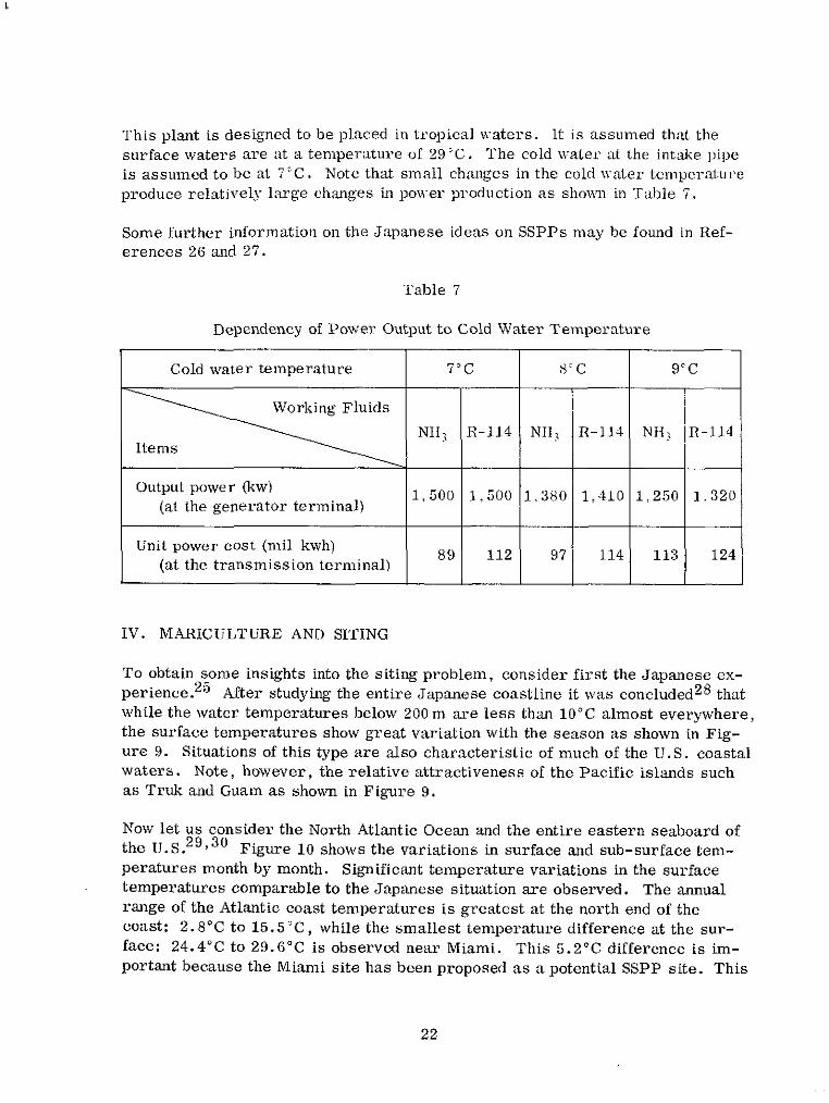
This plant i s designed to be placed in Lropical waters. It is assumed th:tt the surface waters a r e at a temperature of 29'C. The cold n:ater at the intake pipe i s assumed to be a1 7'C. Note that small changes in the cold \valer tcniperature produce relatively large changes UI power production a s shormi ui Table 7.
Some further information on the Japanese ideas on SSPPs may be found in Ref- erences 26 and 27.
Table 7
Dependency of Power Output to Cold Water Temperature
IV. MARICULTURE AND SITING
To obtain some insights into the siting problem. consider first the Japanese ex- p e r i e n ~ e . ~ ~ After studying the entire Japanese coastline it was concluded28 that while the water temperatures below 200m a r e less than 10°C almost everywhere, the surface temperatures show grea t variation with the season a s shown in Fig- u re 9. Situations of this type a r e also characteristic of much of the U.S. coastal waters . Note, however, the relative attractiveness of the Pacific islands such as Truk and Guam as shown in Figure 9.
Cold water temperature 7'C
Now let us consider the North Atlantic Ocean and the entire eastern seaboard of the U.S. 29 ,30 Figure 10 shows the variations in surface and sub-surface tem- peratures month by month. Significant temperature variations in the surface temperatures comparable to the Japanese situation a r e observed. The annual range of the Atlantic coast temperatures i s greatest a t the north end of the coast: 2.8"C to 15.5 "C, while the smallest temperature difference at the sur- face: 24.4"C to 29.G°C is observed near Miami. This 5.2"C difference i s im- portant because the Miami site has bcen proposed as a potential SSPP site. This
R-114
1.500
112
8'C
NH3 Items
-
NI~I,
1.380
97
9°C
Output power (kw) (at the generator terminal)
Unit power cost (mil kwh) (at the transmission terminal)
R-114
1,410
114
1 ;
1.250
113
1,500
89
R-114
1 .320
124

Months
Figure 9. Monthly Variation of Sea-surface Temperature in Japan and Tropics

Figure 10. Annual Cycle of Monthly Average Surface Temperature, Bottom Temperature: Surface Salinity, and Computed Surface Sound Velocity at Five Lightships and Lighthouses and for a 1" Square of
Miami Area. Based on unpublished data of Woods Hole Oceanographic Institution files (1958-1961 for lightships and lighthouses and
1940-1961 for Miami area).29
temperature difference can greatly influence the efficiency of an SSPP and even cause an SSPP ciemonstration project to fail. Note the advantage of a tropical SSPP with a maximum tcrnperature difference of only 2°C. Figure 9 shows Truk and Guam to be better SSPP sites than Miami on the basis of A T consider- ations. Figure 11 shows some further information on temperature-salinity var- iations. On the other hand if one is constrained to build an SSPP near the U.S. mainland, Miami is the best site available on the east coast. Figure 12 shows the surface temperatures during the critical month February indicating that one observes temperatures up to 24°C at Miami. Notice that Figures 12 and 13 tend to rule out the possibility of a horizontal temperature gradient SSPP. The temperature differences at various places off the North Atlantic coast in Febru- ary appear to be sufficient (marginally) to achieve a 1.25% efficiency. Howcver,

Figure 11. Polygons Show-ing Monthly Average Salinities and Temperatures for 1956-61 (except for Miami, which has a
longer period). Based on same data as used for F i b ~ r e 10 . 2 9

Figure 12. Surface Temperature of Western North Atlantic Ocean During February. Based upon unpublished data of 1940 to 1970 in
files of Woods Hole Oceanographic Institution: 13,900 observations within about 200km of shore and 11,800 observations farther at sea.
Isotherms on land are from Climatology Unit (1943), and areas where icebergs o r heavy sea ice were seen between 1911 and 1940
(cross-hatched) are from Weaver (1946) .~~
look at Figure 13. Ln August these temperature differences all but disappear. There is a gradual decrease in the temperature difference from February to August and a horizontal gradient SSPP would be efficient for only two months of the year. It is also interesting to note that the surface temperatures nea2 the Gulf coast in February are about 15°C; insufficient to operate an SSPP.
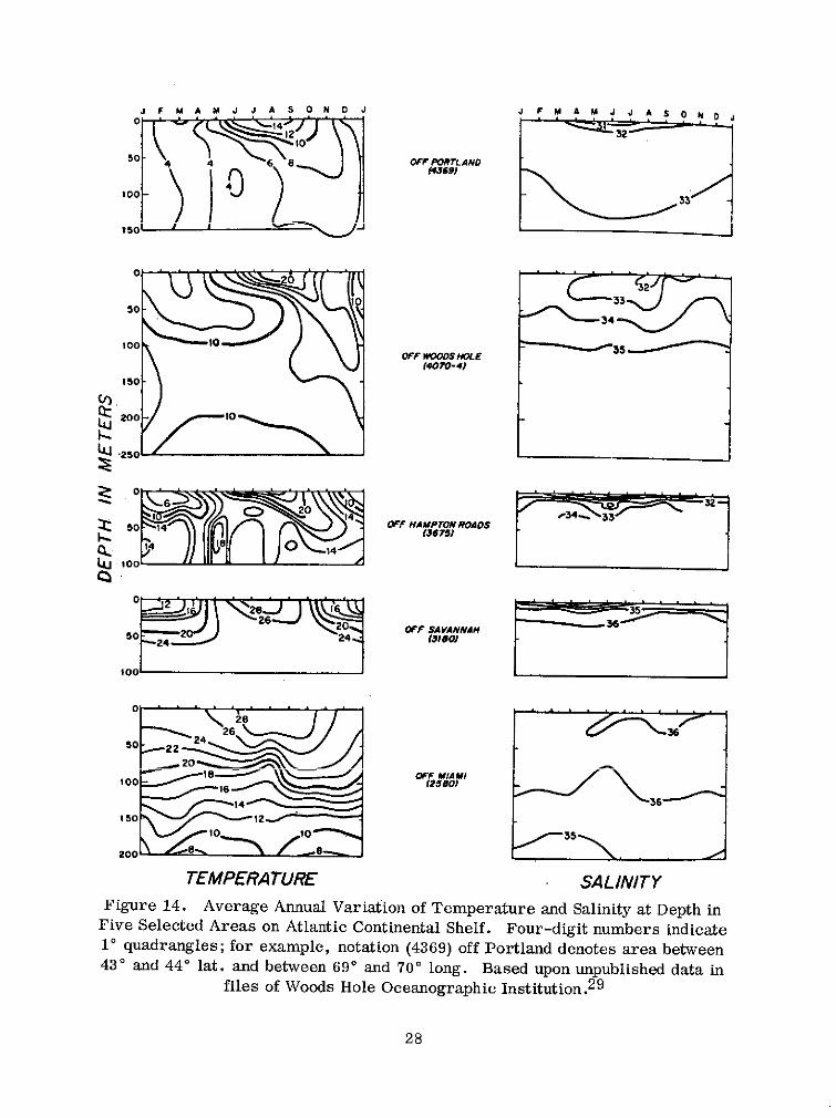
Thus the only viable potential SSPP site off the coast of the U.S. appears to be the Miami site in the Gulf Stream or Florida current. That part of the Gulf Stream between the Strait of Florida and Cape Hatteras is usually called the Florida current. Another reason for selecting Miami as a prime site is the temperature behavior of the subsurface waters as shown in Figure 14. Only off Miami does the temperature decrease with depth throughout the year, elsewhere it decreases only during the summer. At a depth of only 200 meters one begins to find temperatures of 8°C at the Miami site.

Figure 13. Surface Temperature of Western North Atlantic Ocean During August. Based on unpublished data of 1940 to 1970 in files
of Woods Hole Oceanographic Institution: 18,500 observations within about 200km of shore and 19,400 observations farther at sea.
Isotherms on land and areas of iceberg and heavy-sea-ice sightings as for Figure 12.29
Therefore it is reasonable to recommend the Miami site as the prime mainland U.S. offshore SSPP site. The various tropical sites a r e better for the purposes of demonstrating SSPP concepts 'and feasabilities than the Miami site.
At this point the prime sites for SSPP construction need not be gone into in de- tail. It is recommended that the prime sites for SSPP construction be:
Puerto Rico (south coast)
St. Croix, U.S. Virgin Islands (north coast)
Hawaiian Islands (various sites)
The various U.S. Pacific Islands (Micronesia): Largest sea thermal resource in the world - 5,000:000 square miles
Miami, Florida
J F M A M J J A S O N O J 5:rm 1 0 0
1 5 0 L ---A
0
5 0
1 0 0 OFF W r n E
rmm-41 1 5 0
v,
E
TEMPERATURE SALINITY Figure 14. Average Annual Variation of Temperature and Salinity at Depth in
Five Selected Areas on Atlantic Continental Shelf. Four-digit numbers indicate lo quadrangles; for example, notation (4369) off Portland denotes area between 43" and 44" lat. and between 69' and 70" long. Based upon unpublished data in
files of Woods Hole Oceanographic ~ n s t i t u t i o n . ~ ~

In addition, there are numerous foreign sites; many in areas lacking electric power and fresh water. Any successful U.S. SSPP would tend to generate great demand by various nations for SSPP technology. The potential payoff here is great. The word "great" is used not only because of the SSPP's power poten- tial, but also because of the SSPP's food and fresh water production capabilities. The food producing capabilities of the SSPP will be discussed. The fresh water production capabilities will be gone into in the open cycle SSPP discussion below.
The discussion of the artificial upwelling induced by the cold water pumping is gone into in References 31, 32, and 33. There is no need to go into the increas- ing need for food worldwide at this time and the projected increased need for food due to increasing population in the next few decades. We have recently wit- nessed famine conditions in Central Africa, South America, India, Bangladesh, Burma, and in other localities. The SSPP concept offers, in addition to its power production capabilities, the gift of mariculture. One may define mari- culture, for our purposes, to be synonomous with ocean farming. Mussel farm- ing has proved very successful in Spain and the Japanese have large oyster cul- ture operations. The farming of shrimp is becoming commonplace and fish have been raised for centuries. The selection of breeding stock for mariculture is a well established science.
For an adequate period of time an algae growth plant (farm) was proved success- fu1.34 Algae (chlorella pyrenoidosa) growth rates of 14.4g of dry algae per square meter per day were achieved. In this experiment a nutrient medium was used. The nutrient medium associated with the SSPP is the ocean itself. Deep ocean water (the cold water used for condensing purposes) is many times richer than surface water in nitrates, phosphates and silicates, which are essential nutrients for phytoplankton growth.
One can route the SSPP condenser (nutrient rich) water into lagoons, tanks or ponds where it will stimulate the photosynthetic process by providing the neces- sary nutrients. The phytoplankton concentration in the mariculture system may then be used to obtain optimum yields of shellfish, shrimp larvae, filter feeding fish, etc. Efficiencies of 70% have been obtained for Euphausia Pacifica feeding on Dunaliella. Efficiencies of 55% for brime shrimp, Artemia, feeding on Dun- aliella have been obtained. However, assume only a 10%) rate of phytoplankton conversion to a secondary producer. This 10% conversion operating on a single acre would yield 20 tons of secondary producer per year. Note that mariculturc can also be accomplished in the open sea by the artificial SSPP upwelling system.
Roels et al.32 chose a site 1.6km offshore from St. Croix where a 1000 meter ocean depth was found to occur. They found that the deep water, in addition to its nutritious values, was free of human disease producing organisms, shellfish parasites, predators, fouling organisms and man-made pollutants. They pumped this water onshore andgrew clams, oysters and scallops tomarket size in a year.

The financial rewards from a mariculture system can be greater than that that can be realized by the sale of power. The mariculture system is exceedingly desirable, but there remain two major a reas of concern.
How will a new large source of nutritious water affect the ocean ecology of a given area? One may not assume that because one has greater growth of algae, shellfish, fish, etc. the effects are beneficial. This should be studied in a pilot SSPP and natural upwelling areas should be studied more closely.
e International law must allow for the harvesting of the SSPP's mariculture products in international waters without interference by others. Security may also be a problem. A method of obtaining fees from fishing vessels operating in the SSPP upwelling area should be legislated internationally.
V . MATERIALS
Instead of going into the advantages and disadvantages of various materials for SSPP construction (hull, cold water pipe, heat exchanger housing, etc.) let us state from the start that a complete evaluation of over a dozen potential struc- tural materials for SSPP use has been made. In this study structural strength, corrosion resistance, manufacturing and assembly difficulties, initial cost and maintenance costs were taken into consideration and the decision process deter- mined concrete to be the best choice for SSPP construction (at any ocean depth above the thermocline). Therefore let us only describe some of the advantages and roperties of concrete and the reasons concrete is appropriate for SSPP use. 5'5
The Romans were among the first to use concrete in a niarine environment over 2000 years ago.36 In fact the f i rs t century concrete pillars erected in the Bay of Pozzuoli are still serviceable after 1900 years underwater. It is doubtful if any metal could have withstood the corrosive action of the sea for this length of time. first reinforced concrule structure for maritime use was built in Southampton, England in 1899 and was in service and in excellent condition in 1955. However, the 1928-9 precast concrete used in the San Mateo-Hayward Bridge (San Francisco Bay) required extensive repairs to the corroded rein- forcement. This experience tends to rule out the use of high porosity concrete in marine environments.
Many floating concrete structures have been successful. The first were Lam- bot's (1848) 1 0 foot reinforced mortar rowboats, one of which was afloat more than a century later. Nervi in 1946 built the ferro-cement vessel, Irene, which displaced 165 tons and had a hull almost 1.5 inches thick. After eight years of

ocean service the Irene needed no maintenance. The 2500 ton concrete ship Armistice, built in England in 1919, survived until scuttled in 1969. It is esti- mated that concrete vessels displacing 500,000 tons have been built.37 The disadvantage of these vessels was that reinforced concrete hulls were heavier than the comparatively thin steel hulls and cargo carrying capacity is one of the crucial parameters in ship design.
The structure closest to the SSPP that has been constructed is the Ekofisk. The Ekofisk is a prestressed concrete oil storage and tanker-loading caisson built in 1971-72 in Stavanger, or way.^' It displaced 215,000 tons floating. It was towed into position - as the SSPP will have to be - in the North Sea and then ballasted with sea water until it rested on the sea bed in 70 meters of water. Once in position, the caisson was anchored by its own weight plus the weight of its contents with no additional anchorage. This concept applies to the SSPP an- choring system as well as the SSPP itself. In the Ekofisk situation both steel and concrete alternatives were proposed. Concrete was adopted for cost and operational reasons.
One can find in ~ e r w i c k ~ 9 the significant properties of concrete in an ocean en- vironment that apply to SSPPs and maintenance. There are beneficial effects associated with submerging concrete. Generally, concrete submerged in sea water continues to cure and increases its strength in time. The underwater en- vironment is conducive to optimal curing because the hydration water is trapped in the concrcte aad any heat generated by the reaction is conducted away. Shrinkage due to drying will not occur in the underwater environment. There are also no significant temperature changes experienced by the concrete.
One must still worry about permability. The effects of pressure on curing must be taken into consideration for the cold water pipe (depths on the order of 1,000 meters) but not for SSPP structure. This tends to be a significant fact to be overcome in designing concrete cold water pipes. This is because it is not ad- visable to place the SSPP below (or much below) the thermocline and it has been shown that concrete cured in 200 feet of water is dense and strong. However, it has been shown that concrete cured at GO0 feet has less strength.40 Marine organisms will be a problem adding weight, changing friction coefficients, and reducing strength by boring. It is not practical to try to design the concrete resistant to biofouling; one can live with it on the structure with insignificant loss in any of the desired structural and dynamic properties.
The problem of the cold water pipe will be considered later and the type of ma- terial adequate for its construction will be analyzed.

VI. THE NITINOL ALTERNATIVE
Prior to discussing heat exchangers, turbines, working fluids, etc. , we will delve into a viable alternative to the "evaporator-condenser" SSPP process; the Nitinol engine.
Figure 15 adequately describes the qualitative features of Nitinol-55. (1) The material can be obtained in practically any shape desired, then (2) the material is deformed into the configuration one desires the material to remember for a11 time. (3) This "historical" shape is then clamped in a fixture that constrains the memory configuration. (4) The Nitinol is then heated (this fixes the defor- mation history in the material) and (5) cooled. The material can now be de- formed into its "working" shape, or some intermediate shape. The material upon being heated to its recovery temperature will return to its historical shape. This process can be repeated many times - up to millions of cycles. When Ni- tin01 is heated and induced to return to its historical shape it exerts considerable force and can do significant mechanical work. It is this property that allows one to design an SSPP Nitinol engine. Figure 16 shows that the recovery at the 6% constant strain level is practically constant and does not fall off significantly after many cycles.
One of the advantages of Nitinol for SSPP applications is that it is not susceptible to s t ress corrosion in sea water.42 The corrosion resistance of Nitinol in stag- nant sea water has not been determined with certainty.
A Nitinol engine with certain characteristics applicable to SSPP's has been pat- ~ n t e d . * ~ Figure 1 7 illustrates the basic principles involved in the design. A strip of Nitinol is deflected, at the subsurface (cold) water temperature in the SSPP, by an amount Z by a weight W,. A second weight W2 is added after the maximum deflection Z is attained. The SSPP surface water (warm) then is brought in to flow over the Nitinol.
The temperature of the surface water is sufficient to exceed the Nitinol transi- tion range temperature and return the Nitinol to its zero-deflection or historical configuration. The amount of useful work performed (WIZ + W2Z) is greater than the work used to deform the Nitinol initially ( W I Z ) . Thus the Nitinol strip has converted the thermal energy of the ocean into mechanical energy which can then be converted into electrical energy by standard procedures. The fatigue strength of Nitinol is high both in the pre- and post-transition temperature ranges and as shown in F i y r e 16 , there is no significant decay in percent re- covery with increasing cycles. The data also indicates that one should not use strains above 8% insofar as this strain appears to be in the vicinity of the max- imum recovery stress and work. Efficiencies of 25% have been obtained and it is hoped that SSPP Nitinol can be designed to operate appropriately and highly efficiently at temperature differences one observes at the prime SSPP sites.

1 0 OBTAIN 55-NITINOL IN A BASIC SHAPE wire, rod. sheet, tub. exvusion. carting. etc.
121 FORM THE DESIREO"MEM0RY CONFIGURATION" w 131 CLAMP MEMORY CONFIGURATION IN A F IXTURE @ D @
Heat to about 9 W " F Cool
14) GlVE MEMORY HEAT TREATMENT IMHTl
(5) STRAIN T O T H E INTERMEDIATE SHAPE
161 GlVE RESTORATIVE HEAT TREATMENT (RHTI 1300 l o
+275" F depending on cornposltlon)
171 COOL TO AMBIENT TEMPERATURE
step. 5 to 7 can be repeered
Figure 15. The Nitinol Deformation-Memory Process
- w 6 percent constant strain
95 A * U u " - " b
- 8 percent constant strain .. - - . j I I I I T T
Number of Cycles
Figure 16. Shape Recovery Fatigue Curve for 0.20 in. Diameter Nitinol Wire

Figure 17. Schematic Diagram Illustrating the Conversion of Heat Energy to Mechanical Energy Using 55-Nitinol
More research and development work must be done to perfect a Nitinol engine for SSPP applications, but the work that must be done to perfect heat exchangers, turbines and the peripheral equipment for a closed cycle SSPP is an order of magnitude greater than for the equivalent Nitinol development. From prelimi- nary calculations it appears that Nitinol engines will cost less than the equiva- lent closed cycle systenls proposed, however, an adequate system design must be performed prior to an unequivocal statement of this nature. To summarize the Nitinol engine SSPP is a v i h l e concept. It offers some important advantages over some closed cycle SSPP designs. however, it has not been proven in the hardware sense. It is recommended that any decision to proceed with the closed cycle SSPP concept should proceed concurrently with research into the area of the Nitinol SSPP alternative.
W. THE SSPP AND THE CLAUDE CYCLE
One reading the popular scientific literature, concerning the various proposals for the SSPP, inevitably comes across statements to the effect that the Claude process is not workable o r it is inefficient and that an open cycle system is not even t~ be ~~ ' i o i i s iy coiisiliareli when compared to ciosed cycle SSPP designs. When one attempts to do some detective work and track down the source of these statements in the scientific and technical literature one finds more of the same types of statements. There a re , indeed, serious technological difficulties in- volved in an open cycle SSPP design, but these difficulties may be orders of magnitude smaller than those difficulties associated with closed cycle SSPP designs.
It must be pointed out that the first SSPP proposals were tied to the closed cycle. The closed cycle advocates were the Frenchman DtArsonval, the American

Campbell and the Italians Dornig and Boggia. Claude was early to recognize certain deficiencies in their ideas:7
"The inventors referred to proposed a means, namely, the use of liquified gases, vaporized under pressure by the tepid surface water, and then condensed by the cold water after their expansion in a motor. Manifestly such a solution is burdened by a number of inconveniences, one of them being the high cost of such evanes- cent substances, and another the necessity of transmitting enor- mous quantities of heat through the inevitably dirty walls of im- mense boilers with such a small difference of temperature."
These words are as applicable to the closed cycle SSPP concept today as they were in 1930 when they were written. The closed cycle technology of the year 1930 was relatively advanced. In fact many of the fossil fuel power plants in our major cities were built before 1930 and are still in operation today.
Recall that Claude successfully demonstrated the open cycle with a 60kw SSPP at ~ u g r b e , Belgium. A 2Q°C AT created enough steam to run a turbine with a one meter diameter wheel at 5,000 rpm. At his Cuban plant Claude used a 14°C AT to generate 22kw of electric power. The pressure in the boiler was 23 mm at 25°C and the pressure in the condenser was 1Gmm at 15°C. Claude also showed that the efficiency of an SSPP increased as (AT)'. Thus the importance of obtaining the largest temperature difference possible.
The objection to the open cycle on the basis that the pressures generated by the steam are so small so as to be useless is the primary objection presented by the open cycle detractors. Claude was also stung by this criticism and stated:
"However, we had hardly uttered our proposition before protesta- tions and objections fell on our heads like hail. First of all, so extremely low is the pressure of such steam that everyone doubted that it could be utilized; and it is strange, indeed, that no one had conceived of its possibilities prior to the very deviser of processes employing the highest pressures ever used in industry . . . 1 ,
Figure 7 is a schematic of an open cycle SSPP. This type of plant has its basis in the fact that one can lower the temperature water boils at by lowering the pressure upon it. Thus in Figure 7 the tepid ocean surface water will boil in the flash evaporator because the air has been evacuated from the chamber caus- ing a partial vacuum in it. The steam generated thereby spins the turbine. The steam is then condensed via the cold deep ocean water. This condensed steam is pure (desalinated) water and constitutes one of the truly significant advantages of the open cycle over the closed cycle.

Davitian and ~ c ~ e a n ~ ~ object to the Claude cycle on the basis that the SSPP vapor pressure of only 25-30 mm-Hg would require very large turbines. They estimate that for a one million kilowatt plant a football field size nozzle throat would be required. Othmer and Roels attempt to answer this and other objec- t i o n ~ . ~ ~ It is perhaps unreasonable to build a one gigawatt SSPP with its 10,000mz nozzle throat. A series of 10 megawatt SSPPs may be preferable to one very large SSPP. Even though the turbines for the open cycle SSPP are relatively large the pressures and temperatures under which they must operate a r e relatively small. Thus these turbines can be made of lightweight materials such a s plastics, fiberglass, composites, etc. It may be cheaper to build large plastic turbines than to build the relatively smaller, but stronger, closed cycle turbines.
The open cycle SSPP has the potential to produce up to 25'5 more power than the closed cycle SSPP. The reason for this is that there is no loss in temperature in the exchange of heat from the tepid surface water to the working fluid in the open cycle process. Also in the closed cycle SSPP the heat exchangers are the most expensive component of the plant. This cost is saved if the Claude proc- ess is used. Moreover, one need not contemplate the loss of volatile or hazard- ous working fluids in the open cycle.
Closed cycle systems are extremely sensitive to biofouling of the heat exchang- e rs . This problem may severely limit the life of any closed cycle SSPP. Since boiling in the open cycle SSPP is primarily dependent upon the vacuum and not the temperature of heat transfer surfaces the biofouling constraint does not ap- proach the criticality it does with the closed cycle case. If biofouling is the factor that most severely limits SSPP life, an open cycle SSPP would survive a great deal longer than a closed cycle plant. Even the Nitinol engine will be sus- ceptible to biofouling and the formation of slime on the surface of the material which progressively cuts down on the transfer of heat from the tepid (and cold) water to the material will drastically cut down on its efficiency.
&I equally convincing reason for building SSPPs with open cycle power genera- tors was adequately described by ~ a r n e a . ~ ~ All SSPP designs make use of mas- sive amounts of cold deep ocean water, therefore no one design possesses any significant advantage over any other with respect to mariculture considerations. However, the Claude cycle SSPP is the only system under consideration that produces fresh water as a byproduct. The United Nations does not foresee any long term energy shortages, but predicts serious water sho, tages . Othmer and Roels state47 "if the cost of producing power is taken as 6 mills per kilowatt hour, fresh water costs are $1.38 per thousand gallons; or if power cost is taken as one cent per kilowatt hour, then fresh water costs $1.28 per thousand gallons. " Thus a small SSPP built with off-the-shelf hardware could

produce power at a cost of one cent per kilowatt-hour. But consider now the fact that many islands which are prime SSPP sites have shortages of water. Also many countries with prime SSPP sites are largely desert and the water desalinated by a Claude cycle SSPP may be more valuable than the power pro- duced. Even at the Miami site there a r e fresh water problems due to incessant pumping and use of the subsurface water. The aquifer level has been danger- ously lowered and salt water intrusion into the aquifer is becoming a serious problem. A new fresh water source would be very welcome there.
In any case the value of the distilled and desalinated water produced in the SSPP by condensing the steam should be several times the value of the power produced .45
To summarize, the Claude (or open) cycle SSPP is the most attractive concept that has yet appeared. It offers the following advantages:
(a) No loss in temperature due to the use of heat exchangers (increased power production)
@) No need for expensive heat exchangers
(c) The production of desalinated and distilled water
(d) Relative immunity to biological fouling of surfaces
(e) Inexpensive turbines required
( f ) Claude cycle SSPP technology will create the greatest demand for SSPPs by many nations due to (c) above.
It is therefore recommended that the Claude cycle SSPP be given first priority for research, development and construction.
It does not appear to be reasonable to put "all our eggs" in the closed cycle basket given the heat exchanger, biofouling, etc. problems associated with that system.
VIII. THE CLOSED CYCLE SSPP
Figures 3 , 4, 5, G and 8 illustrate the basic principles of the closed cycle SSPP operation and some of the variations that have been proposed. These SSPPs have been discussed to some extent in Section 111. Most of the research done in the past few years has been associated with the closed cycle SSPP. Therefore in this section the various components of the closed cycle SSPP design will be analyzed even though these components can be used in the Claude o r Nitinol

designs with little or no modification. This also presents the opportunity to re- view the technical problems associated with SSPP designs in general. Let us begin with the most difficult problem first. The problem is both economic and technical and is associated with the closed cycle SSPP only.
A . Heat Exchangers
~nderson48349 arid others have accurately observed that the greatest economic problem in the construction of a closed cycle SSPP is the construction of low cost heat exchangers. The greatest technological problem in closed cycle SSPP design is to design and build heat exchangers that transmit approximately 30 times a s much heat per kilowatt as is now being done by the heat exchangers in typical fossil fuel power plants. Moreover one must perform this feat while making use of much smaller temperature differences than those at which con- ventional power plants make use of in their operation. The small AT and the need for very high efficiency dictate to the SSPP designer that he must design massively large heat exchangers. Now since the heat exchangers will neces- sarily be large, one must find a way to keep the cost down and then insure long lifetimes for the heat exchangers so as to make the SSPP investment attractive.
The Carnegie-Mellon University heat exchanger design consists of hexagonally nested 10% pipes, one inch in diameter, through which the tepid surface water is pumped and the working fluid, which flows around the pipes, is consequently boiled. On the water side of the tubes, the tepid water flows with a velocity of 8ft/sec. The temperature losses that are intrinsic properties of this heat ex- changer design a re the following: a loss of 4°C through the 3mil film, a 2°C loss through the aluminum tube wall? and another 4°C loss through the 3mil film on the working fluid side with working fluid having been imparted a velocity of 8ft/sec. This adds up to a total loss of 10°C due to the heat exchanger oper- ation. Since one has only a AT of the order of 20°C, one half of the available AT is dissipated by the heat exchanger's operation.
The CMU design also incorporates 25 mil depth flutes on the outside , or working fiuid side of the heat exchmlger pipes. It should be noted that flutes on the tepid water side of the heat exchanger or on the cold water side of the heat exchanger (condenser) would create near optimum sites for biological growth due to the tendency of the flutes to induce local turbulence.
The UMASS SSPP heat exchanger is of the plate and fin type make of CuNi in a 90 to 1 0 ratio. Plastic was also considered a s a heat exchanger material be- cause of its low cost, as was aluminum. CuNi was chosen in spite of its high cost because of its alleged anti-biofouling properties.

A mathematical model that characterizes the SSPP evaporator, turbine and con- denser has been developed at the University of Massachusetts. Let u s now con- sider some of the resul ts of their simulation.
The f i rs t result indicates that compact heat exchangers of a plate-fin design with extended interior exchange surfaces a r e superior to plain tube and shell exchangers. The second result i s that they could not determine the optimum plate-fin heat exchanger design. Small diameter tubes appeay to offer advan- t'ages over la rger tubes, however, one must take the possibility of clogging into consideration and also the difficulty involved in manufacturing small diameter tubes. Figure 18 graphically illustrates some of the above mentioned results. Contrary to the CMU experience the UMASS study indicates that none of the cur- rent enhancemeilt techniques will succeed in raising the heat t ransfer efficiency over that obtained with internally extended surfaces.
I t appears that the L'RIASS system considers the problem of biofouling of the heat exchanger external surfaces a bit more seriously than the CMU designs consider it to be. In Reference 1 7 recognition i s given to the fact that exposing the heat exchangcr surfaces to sea water causes those surfaces to become cov- ered by a thin film of microbial growth that will essentially greatly reduce the efficiency of the boiler and condenser. However, they quote a 1948 paper51 and dismiss the problem. The resul ts in Reference 51 indicate that one par t in four million of clovine i s sufficient to prevent microbial growth. I t ' s doubtful that the resul ts in Reference 51 apply to the heat exchanger situation in an SSPP with its massive flows of watcr and continuously distributed points of localized turbulence. To the UMASS people21 biofouling remains an unresolved problem. They quote References 52 and 53 to back up their statement. They present three basic biofouling prevention methods (to be applied in light o r dark situations).
e Move the tepid water past the boilers with a velocity grea ter than 2 . 2 knotss4
Use CuXi to construct the heat exchangers t o prevent b i ~ f o u l i n g ~ ~
Continuous wettin of the heat exchanger surfaces with a sodium hvypo- chlorite solution 5f
Thus both groups have adopted the philosophy that the biofouling problem can be easilj- solved and it is only the economics of the solution that gives any cause fo r concern. Little concern i s given to the fact that one must pump on the order of 5,000,000 gal/min of tepid water past the boilers and about twice that, o r 10,000,000 gal/'min, of nutritious cold bottom water past the condensers which will warm it up a bit . hforcover, the creation of an artificial up\velling' zone surrounding the SSPP implies that even the tepid water will be saturated with

PLAIN TUBE, AMMONIA
PROPANE
INTERNAL FINS, AMMONIA
I I I 0.5 0.75 1.0
TUBE DIAMETER (in)
Figure 18. UMASS Heat Exchanger Study Results
nutrients conducive to biological growth and, indeed, this water will have an increased number of organisms that are potentially detrimental to SSPP heat exchanger heat conduction properties.
It is evident that biofouling is the most serious problem associated with heat exchanger design especially because of the small AT available and the high ef- ficiency that the SSPP must operate at to be classified a s successful. The pro- jected lifetimes of the SSPP heat exchangers a r e 25 years for the CMU design and 40 years for the UMASS design. None of the methods proposed for biofoul- ing prevention can be successful in an open system for any length of time. Con- sider the wide range of conditions under which life can sustain and reproduce itself. Organisms can grow in acidic and basic solutions. Organisms grow in very cold regions; Antartica, and in very hot regions; hot water pools in Yellow- stone National Park. They have also been observed flourishing in nuclear reac- tors constantly being irradiated by many thousands of times the radiation dose that would quickly be fatal to humans. Lile exists a t very low pressures and very high pressures from top of Mount Everest to the bottom of the oceans and in the deepest mines. Indeed, it is these facts that form part of the basis for NASA's Viking mission - t o land an automated scientific payload on the surface of ~ a r s . ~ 7 ~ 5 ~ The reasoning being that if life can exist on earth under the most extreme conditions there is a good possibility that life exists on Mars. Thus far one basic principle has emerged in the study of life under extreme conditions: where there is water there is life. And where there is an SSPP there is a lot of water. Note that it does not take very much biological growth mass to destroy an SSPP heat exchanger's heat transfer characteristics. To design against this sort of contamination, in an environment where one is constantly recirculating massive quantities of sea water, one might have to use a non-trivial amount of the power produced by the SSPP, or design somewhat expensive antifouling sub- systems, or replace the heat exchangers as they become fouled (throw aways), o r use expensive materials, or use chemical retardants, or use some combina- tion of the above five panaceae.
It is very difficult to use the existing data on biofouling. This data was obtained for ships, pipes, offshore structures and at best large AT power plants or en- gines. It makes little difference if there is a microscopic layer of biological growth on, say, the interior of a water pipe or an SSPP cold water pipe - it might even improve its flow characteristics. However, this same microscopic layer can be catastrophic to the efficient operation of an SSPP heat exchanger.
Before any consideration i s given to the construction of a closed cycle SSPP it is recommended that the biofouling problem be thoroughly studied by means of basic experiments and the testing of models of SSPP heat exchangers with vari- ous materials and different methods of preventing biofouling. Data must be ob- tained on the degradation of heat transfer characteristics with time in the ocean environment at the prime SSPP sites.

Corrosion, s t ress corrosion and to a lesser extent corrosion fatigue and mate- r ial aging a re likely to present some difficultics in the design of the heat ex- c h a n g e r ~ . ~ ~ , 60 The corrosion problems are not serious in that one can design corrosion resistant structures and compone~,ts. In the heat exchanger situation one must optimize heat transfer characteristics: in conjunction with optimizing anti-corrosion properties. If one pel-forms this optimizati~r. with cast as a constraint it may turn out to be a somewhat difficult chore with some difficult trade-offs taking the designed lifetime of the SSPP as another constraint.
In addition to the choice of material there are other means available to augment heat t r a n ~ f e r . ~ ~ . ' ~ One attractive technique has been proposed by Y O U J I ~ , ~ ~ and Young and ~ u m m e l l . ' ~ Spots of teflon or other nonwetting material on the heated surface promote nucleations as shown in Figure 19.
There a r e many other techniques to augment heat transfer (see Ref. 50 for ex- ample), however, most use up more energy than they add by their augmentation.
An interesting alternative SSPP heat exchanger has been proposed by Straws .G4 This alternative involves applying the concepts of heat pipes and thermosyphons in the heat exchanger design. The basic concepts of the functioning of heat pipes and thermosyphons can be found in References 65 through 70. Heat pipes and thermosyphons are both sealed objects, commonly cylindrically shaped. con- taining a fluid present predominately as a vapor. This fluid is at the saturation temperature corresponding to the vapor pressure.
Figure 19. Influence of Surface Treatment on Saturated Pool Boiling

The thermosyphon is a vertical device that transfers heat from below the device, boiling the fluid and raising the internal pressure and temperature. To move towards equilibrium heat must be transferred from the top portion of the ther- mosyphon. This condenses the vapor at the top and the liquid returns under gravity to the evaporation portion of the thermosyphon.
The heat pipe is a thermosyyhon wherein the condensate flows under the action of capillary forces, rather than under the action of gravitational forces as in the thermosyphon. In designing an SSPP heat exchanger one may make use of both gravity and capillarity.
In practice the heat pipe is simply a tube or duct whose wall is clad with a layer of porous material, usually called the wick, as shown in Figure 20. Since both evaporation and condensation can occur at almost the same temperature, the to- tal temperature drop over a heat pipe may be very small, a few degrees or so, as in SSPP applications, whereas the heat transported may be of the order of kilowatts. The effective thermal conductance can, therefore, be more than tens of thousands of times that of a copper rod of the same size. Add the assistance of gravity and one has a truly marvelous heat transfer device. Figure 21 illus- trates the method of obtaining an optimally designed heat pipe.
E Env W C
Figure 20. Simple Cylindrical Heat Pipe. The wall Env of the completely sealed pipe is clad on the inside with a porous
layer W , the 'wick1. The heat entering the left-hand end of the pipe, the 'evaporator' E , causes fluid in the wick to
evaporate. Latent heat is thus taken up by the vapor, and the vapor pressure at that end r ises slightly. The vapor flows from the evaporator through the vapor duct V to the condenser C , where the latent heat is released upon con-
densation. The condensate is then recycled through the wick to the evaporator. In addition to the locations of the evapo-
rator and the condenser - which need not be restricted to the end - the pipe is provided with external heat insulation.
Q hput and output heat

Figure 21. The Working Range of a Heat Pipe. The axial heat flux Q is shown as a function of the tem- perature T. The heat pipe operates in the shaded
area. The limits of T a re the melting point T,,, and the critical point T, of the working medium. The
upper limits of the heat transport in a heat pipe are determined in thc first place by the velocity of sound in the vapor (curve S), and at higher operating tem-
peratures by the maximum liquid-flow rate which the wick is capable of handling (curve W). Other limita- tions are due to the take-up of liquid from the wick by the vapor flow (curve E) and boiling of the fluid
in the wick (curve B) .69
In the SSPP hcat exchanger situation the heat-transport capability is moderate and perhaps it offers no advantage over other heat exchanger suggestions, Fig- ure 22. The heat transport capability of a heat pipe is due in large part to the fact that the thermal rcsistancc of the vapor duct is very small. The heat flux is limited by the heat transfer into and out of the pipe and the evaporation and condensation processes. One advantage of the heat pipe is that it is a reversible unit. Thermal energy may be transferred through heat pipes from either section to the other section. Thus one may use ammonia as a cleaning (and toxic) agent as well as a working fluid simply by niechanically reversing the heat exchangers. This type of design is likely to be expensive and seals will have to be designed. In addition the use of heat pipes or thermosyphons result in the construction of larger heat exchanger units.

Figure 22. Diagram of the Measured Maximum Heat Flux q for Various Working Fluids, and the Temperature at which these are Ordinarily Used. A higher operating temperature corre- sponds in general to a higher heat-transport capability. 69
Thus no matter which way one turns the heat exchangers present a significant technical problem that may not have an economic solution within the given con- straints. This is one major reason for the great attractiveness of the Claude (open) cycle and the relative attractiveness of the Nitinol engine when compared to closed cycle concept.
Once the basic heat exchanger concepts have been decided upon one must select a working fluid and then optimize the heat exchanger-working fluid combination. This task is not simply one of choosing the fluid with the best thermodynamic properties as will be seen immediately below.
B. Working Fluids -
The major contenders for the working fluid job are: (a) ammonia, favored by the CMU group; (b) propane, favored by the UMASS group; (c) the halo-carbon R-12/31, favored by J. H. Anderson; and (d) R-114, favored by the Japanese (see Table 8 from Reference 25). All of candidates yield cycle efficiencies near the same theoretical maximum. Table 9 illustrates some of the UMASS results on working fluids21 (also, see Tables 2 and 3).
The working fluid should be optimized with respect to the heat exchangers and not the turbines, a s the heat exchangers a r e the critical components in the SSPP design and one knows how to optimize turbine operation for (almost) any working fluid.

Evaluation of SSPPs using Various Working Fluids
@ Realizable 0 Probable A Hard X Impossible
Adiabatic Enthalpy Drop 2 K
Turbine Inlet Flow
Turbine Inlet Pressure
Turbine Blade Height
Mean Diameter
Boss Rates
Weak Points
Probability of Realization
1 .64m
0. 6
* a * w E ; F- z " ; m w z w . c 1 E m : w b l l M M * c * orom 4 - 4
0 0 °
r" g F"
A
1.93
0.6
e 0 * 'n ar
k
m 00 5: 2 - 3 6 0 3 0 0 0 0 F F
A
0.5
0.78
n 0 $.
w w
-.m
2; 2 - 3 6 0 '2 0 0
g g
A
1.24
0.77
w M L. 0 - c. w +
2 m B 0 m
0.66
0.66
r M
1.62
0.59
* 2
0.855
0.725
w
O O A @
0 0 0
r"r"g
0.7
0.72
F
2" a
L( m 5 E :: w 5 V) m m a"
0
0.43
0.8
a'
V1 5 m w & F M z h
0.55
0.75
F
2 z $ 2 00
w 2 V) m w a"
0
0.35
0.835
5.2
0.5
* m
5 m 00 : a s M 2 0
g
A
+ 3
$ 2 G m e e r g z m 3 G E g m a w M M * 3 * 5 3 3 0 0 0
g3ng
x

Table 9
Comparison of \6'orking Fluids for Ideal 100-mm Cycle
With respect to the environmental effects in the event of a massive working fluid spill , ammonia will have the smallest environmental impact as it is easily as- similated and dissipated in the ocean. The other three a r e known to be inferior to ammonia in this respect , but their precise environmental effects must be de- termined in advance if they a r e to be used as working fluids.
R-502
Propane
Sulphur Dioxide
Water
C. Turbines
~ n d e r s o n ~ ~ maintains that the turbine design problem has been essentially solved for the case of the closed cycle SSPP. Equivalent research on turbines to be used in conjunction with the Claude cycle SSPP has sorely lagged behind and only partially because it is a more difficult problem. ~ n d e r s o n ~ l has pre- sented an in-depth analysis of the concept, geometry, and optimization of the SSPP turbine, although no design plans have yet appeared for a full scale tur- bine. If ammonia is selected the major turbine problems become the turbine seals and turbine materials. In fact no matter what the working fluid selected, the SSPP cannot tolerate working fluid leakage by way of the turbine shaft seal.
3 .61
3.67
3.72
3.78
140
115
4 5
0.3
103
85
3 0
0.15
4 _ 552
3: 706
634
1 . 4
2,756,000
1.084,OOO
1.041,OOO
155, 500

The crucial material problem centers on the question as to whether or not tur- bine materials can be developed that will deteriorate no matter how wet the ammonia becomes.
The UMASS turbine, selected with the constraint that the working fluid i s pro- pane. will generate 30 megawatts per unit (Table in), The cost is estimated at $65/kw. However, if ammonia is chosen the cost decreases to $35/kw (see Table l o ) .
There a r e many corporations that have many years of expertise in turbine de- sign and development that a r e applicable to low AT, A P processes and there is little doubt that any one of them could produce an efficient turbine in a short time that would meet all the closed cycle SSPP requirements, if a contract with sufficient dollar incentives were awarded. On the other hand the Claude cycle turbine calls for some new concepts and materials and the situation is not as clear.
Table 10
Optimum Parameters for Turbines with Ammonia and Propane as Working Fluids. 48
A . Ammonia Axial Turbine - 100 megawatt total output
1. Specific Speed = 100. Specific Diameter = 1.0
I 2. Use thrce units of 33.3 megawatts each I I 3. Single storage, full periphery entry I I 4. Wheel diameter approxinlately 7 feet I I 5. Wheel rpm about 1800 I
6. Cost: $35/kw
1. Use three units of about 38 megawatts each
2. Single stage. full, periphery entry
3. Wheel diameter approximately 11.4 feet
4. Wheel rpm about 600
5. Cost: $65/kw

D. Cold Water Supply 'and Pipe
It is best to begin this discussion by quoting claude7 who, it appears. was never uncertain about anything:
"Further, the loss of head in the pipe and the excess of density of the column of cold water, for an ogtput of 1 cubic meter and a speed of half a meter pe r second in the tube, caused a depression in the pit of but 3 meters , which shows how little energy is needed to bring up cold water , and how trivial a r e those objectors who condemn the process because of the tremendous amount of work they bclievc will be required to pump the cold water. I respect- fully suggest that it is so long since these honorable gentlemen left school that they had better learn again the theory of commu- nicating vessels. As a matter of fact, the above-mentioned re- su l t s , ohtained with a comparatively small tube in which the losses by friction a r e considerable? a r e very encouraging for the large pipes that will be used in the future."
Claude was correct; thcrc do not appear to be any serious problems associated with thc cold water supply.
The UbWSS group has proposed a welded aluminum pipe aerodynamically shaped. The pipe for a 400 megawatt plant would be teardropped shaped and be 80 ft by 225 f t . Anderson has proposed, for a 100 megawatt plant, a 40 f t diameter pipe made of vertical 8 inch piping. The CMU group proposes a 60ft diameter pipe for their 100 rncgawatt plant. The ~ a ~ a n e s e ~ ~ have concluded that steel i s un- suitable for the cold water pipe, because of the large diameter needed and they maintain that the installation cost i s high in comparison to the cost of the pi e itself. They recommend the use of an FRP pipe they call Takata HF pipe. 7 f This pipe can be shipped folded flat and then inflated and cured by a i r and heat at the SSPP construction site. They recommend that the upper portion of the pipe be reinforced near the top to protect the pipe against wave damage.
In any case one should design the pipe keeping in mind that certain potential problems may arise.18
(a) Vortex induced loading and the pipe's response
(b) Internal fluid flow and pipe instability
(c) The coupling of (a) and (b)
(d) Water hammer effects

(e) Response of pipe to wave induced motion of SSPP
(f) Fatigue and corrosion fatigue associated with the loading generated in (a) - (e) above.
Fnr streamllh-ed c rnss section pipc such as the UMASS design one should con- sider local subsurface currents (flow directions a r e not always constant with depth) that would tend to apply bending moments to the cold water pipe. Roels, et a1.32 report on successfully operating a small diameter 870 meter deep cold water pipe. The pipe is made of polyethylene and ~ o e l s ~ ~ reports that it func- tions quite well.
I t appears that the pipe problem can use some innovative thinking in t e rms of materials. To begin with a detailed analysis of the loads any given pipe will experience should be performed. One should consider flexible a s well as rela- tively rigid materials. Lightweight composites might also do the job adequately. In fac t , flexible material would possess the property of being immune t o small bending and torsional s t r e s ses .
Insofar a s the cold water pump is concerned there a r e no technical problems; only problems of optimizing the pump efficiency and liletime. There a r e many companies which have experience in building the kind of pump requircd for SSPP application. Thus the pump, like the closed cycle turbine, appears to be a prob- lem in thc judicious selection of off-the-shelf hardware. On the other hand the design of the cold water pipe involves some innovative thinking, analysis and design, and the 'esult could be greatly reduced cost and greatly increased reliability.
E . Mooring ,and Anchoring
The UMASS group has calculated the horizontal load on their SSPP at the Miami si te . This load is on the order oC 16,000,000 lbs. Some problems associated with mooring a system with these kinds of loads a r e discussed in Reference 18. The moorings needed by SSPPs must be easily deployablc. have lifetimes of 25- 40 yea r s? be capable of being repaired relatively easily and have almost loo%, reliability. The offshore oil platform technology has advumced to the point whcre one million pound mooring lines a r e state-of-the-art for semi-submersible plat- forms. One should talre note of the fact that the Navy deployed a mooring in 6,000 ft of water and the mooring failed due to corrosion in 4.5 years .
The problems associated with anchoring and moor~ng c:ul be solved. but the cost o l the moor-anchor system that meets all requirements may be grea t . The moor and anchor (or massive weight resting on sea floor, a s Heronemus' pro- posal for a football fleld size barge sunk to the bottom) system is one that \u'~ll

experience continuous dynamic (random) loading. The s t r e s s corrosion. cor- rosion fatigue and fatigue problems a r e critical especially near the sea floor where :I significant s tat ic hydrostatic load will be superimposed upon the tly- namic loads associ:ited with the motion (vertical and horizontal) of the SSPP itself.
Further consideration should be given to floating SSPPs to ascertain if station keeping can be maintained with a minimum of power expenditure. o r by directing the hot and cold water effluents. Placing SSPPs in currents such as the Gulf Stream should be ca1,efully evaluated as to the loads imposed on mooring sys- tems. Finally. the cost of mooring and anchoring may make the shorc based SSPP the more attractive concept.
F Human Factors
Any ocean-based SSPP will have to be manned by a crew of about a dozen people. In the construction phase many more people will be needed. The SSPP must be designed so that rescue and escape, in the event of an emergency. can be ac- complished quickly and efficiently. One must take preventive measure against the leakage of hazardous working fluids. Some consideratioll should be given to underwater escape and submarine rescue.
The SSPP should he designed so that the m,aximum possible number of repairs can be made without the use of divers . The SSPP can also be designed to be capable of r is ing to the surface by say , uncoiling par t of the mooring cable. s o a s to make r epa i r s on the surface. The SSPP could also use this system to go deeper to escape from especially severe (50 year) s torms.
It is expensive to equip an ocean-based plant for human habitation and even more expensive to pay a crew to live on the SSPP. One will have to design the SSPP s o a s to minimize the crew size. An optimization study will have to be made (three eight-hour shif ts?) to get the required tasks performed with a minimum of personnel and st i l l have sufficient manpower available to deal with emergency situations.
M. COMPLEMENTARY AND AUGMENTED SSPP ENERGY SYSTEM
The primary objective and motivation fo r building and operating an SSPP i s to provide the U.S. with an additional source of energy to satisfy demand and help make the U.S. self-sufficient in energy. To accomplish this end it is incumbent upon one to consider combining certain energy sources and systems to obtain a s large and concentrated an energy source a s possible. A schematic summary of the various concepts of systems that can augment o r increase the efficiency of

the SSPP plus concepts involving systems to be constructed with o r in conjunc- tion with an SSPP, that can produce power at a lower cost than if built alone: is shown in Figure 23. Another systems schematic from Reference 74 illustrates some associated concepts in Figure 24. Figures 25 and 26 illustrate a Japanese systems concept for an atoll (in Micronesia) based SSPP supporting mariculture and indusirial operations .
It has been proposed to build nuclear power plants in thc ocean, just offshore and on land, but oce'an cooled. There a r e many ocean cooled nuclear power plants. A number of offshore nuclear power plants have been designed and a r e scheduled to be built in the near future. These plants use the tepid ocean water for cooling purposes. Fossil fuel plants abound on our coasts that also use the tepid s e a water for cooling purposes. It s eems obvious that this water (warmer than the tepid ocean water) could be used to increase the AT onc has to work with (see Figure 27). In effect, the SSPP could act a s a partial bottoming cycle for fossil o r nuclear power plants. Depending on the s ize of the power plant the AT in- c rease might not be very big, but every little bit will help increase the efficiency of the SSPP. It seems to make good sense to make use of these power plant's thermal effluent.
Many prime SSPP si tes a r e over o r near geothermal a r e a s , such a s Hawaii. At these s i tes one can construct a geothermal power plant in conjunction with an SSPP. The effluent from this plant may be used to increase the AT the SSPP must work with. In the event a geothermal power plant is not built the geother- mal water can be used directly to increase the operating AT of the SSPP.
The use of so lar ponds. as suggested by ~ a r n e a , ~ ' i s not practical. Tempera- tures up to 95'C can be obtained at the bottom of a solar pond. However, the quantity of water at this temperature is small and hence its potential influence on the SSPP's operating AT would be insignificant.
Wind power plants can be built in conjunction with either the land-based o r the ocean-based SSPP (see Figure 24). Other energy producing systems can a l s ~ be joined to the SSPP a s shown in Figure 23. In the ocean: as long as one has an SSPP on the s i te , one might a s well erect some windmills there.
There is a research program underway to design and develop plans for a float- ing city off the coast of Hawaii (see Figure 28). I t i s planned to use oil burning power generation equipment for this floating city. It seems superfluous to build an oil burning plant over a prime SSPP site. In fact one could combine the float- ing city concept with some of the ideas indicated in Figures 23 and 25 to design an industrial and residential a r e a equivalent to the s ize of a small city.

. . .-
Figure 23. SSPP Complemented and Augmented Energy System Schematic

DISTRtBUTION BY ELEVATION HARDWARE CONCEPTUALIZATION
FLUID & ELECTRICAI- INTERCONNECTIONS
(METERS)
DIRECT THERMAL
PHOTOVOLTAIC WATER PURIFIER
CRYOGENIC LIQUEFIER
MARICULTURE
BASIC PROCESSING
OCEAN REFlNlNGlFlNlSHlNG
THERMAL OPEN -OCEAN PORT
GRADIENT 150
GASEOUS STORAGE
ELECTROLYZER
- -1OW DENOTES RELATIVE MASSIVENESS
OF SYSTEM HAROWAFIE
Figure 24. Typ~cal Systems Location

SBB Current
a -
See Current Kuruma-Ebi Cultivation Area
BarrialBridge
Tranrmision Line
1 /
/ I
Unlwdinp Fsciliw Effluent
wmer From Culfiumian Area
1 Kilometer 1
ocean F ront
/ '/'- ocean
/ / Sea Current
/ ' ----/' SECTIONAL VIEW
l c u t ~ f - a - )
1 Ssndy Sea Bed
Figure 25. A Model Marine Industrial Complex

OCEAN (Upper Reservoir)
TUBULAR PUMP-TURBI NES
I DAM \ ,104kwx 100
-~ - L l k m $ 1-5.5km
i 2100ha 2800 ha 2100ha
LOWER RESERVOIR H.W.L. - 10m L.W.L. - 17m
-2-+ -t-----5km- -2- km km
lkmf /
t D A M TUBULAR PUMP-TURBINES X km l o 4 kw x 100
MAN-MADE ISLANDS
Figure 26. A Plan of Ocean Pumped Storage Plant
One should also look at the industrial thermal effluents associated with the chemical, metal and other industries that can be operated at SSPP si tes and servc to increase the SSPP's operating AT.
X. CONCLUSIONS AND RECOMMENDATIONS
A. The Energy Shortage -
Although a worldu~ide energy shortage will develop in the next few decades. it does p*i>pCsr thzt the ...:= r L ~ c - - - LL+L~. iuty S L ~ L I L I L G U . ~ ~ - : - - - :c . - - s l~ur tages uniii after the
year 2020. If the breeder reactor and solar energy programs prove successful. the U.S. will achieve self-sufficiency prior to the year 2000 and maintain self- sufficiency for an extended period of time.
The main reason for going ahead with concepts like the SSPP is that the world demand for energy, especially in developing nations, is accelerating. The more self-suflicient the U.S. is in energy the more energy that will be made available to r a i se the standards of living in other nations. This is a11 important reason for going ahe'zd with solar energy schemes. Also, since many of the developing nations border on pr ime SSPP si tes in the tropics, the SSPP is an ine.xpensive method of obtaining the necessary energy.
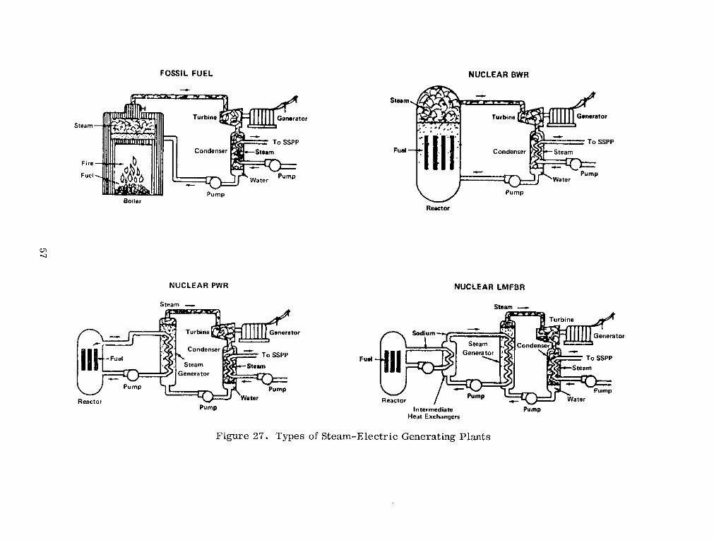
NUCLEAR BWR FOSSIL FUEL
-
Pump
RaYl.r
NUCLEAR PWR NUCLEAR LMFBR
Steam -
Pump Intermediate Pump Heat Exchangers
Figure 27. Types of Steam-Electric Generating Plants

Figure 28. Map of the Hawaiian Islands with Locations of Possible Floating City Sites and the P r i m e Site Selected in Reference 75
B. The Pollutioil Problem
I t must be proven that a r i f i c i a l upwelling on a. massive scale will not cause any ecological d i sas te rs and that there are no detrimental effects due to the opera- tion of the SSPP. Then one may claim that the SSPP is non-polluting and clearly superior to fossi l and nuclear power p l ~ u ~ t s in this respect .
C . Cost -
The SSPP i s very economical (inexpensive) when compared to the costs of other so la r energy l~ l an t s (except perhaps wind power) and fossil and lluclenr fuel plants. However. it is difficult to buclc up this claim without a good s ize SSPP ill operation.
It i s recommended that any SSPP built have a m a ~ ~ i c u l t u r e system dcsigned in conjunction with the power plant itself. As the world food short;igc intensifies

it becomes clear that the value of the food grown with the aid of the artificially upwelled water will exceed the value of power generated, both in human and dollar t e rms . It would be a g ross neglect of responsibility not to proceed with mariculture research and development in conjunction with research and devel- opment on the SSPP and its components.
E . Siting -
As stated in Section IV the s i tes recommended for the location of the first dem- onstration SSPPs are :
c The south coast of Puerto Rico
c The north coast of St. Croix: U.S. Virgin Islands
c Ifawaiian Islands (various sites)
0 U.S. Pacific Islands
(1) Yap Island
(2) Guam
(3) Westcrn Sanloa (Upolu)
(4) Various other Pacific Islands and atolls a r e also viable s i tes
c Miami. Florida
The Miami si te is low on the priority list because of the smaller AT encountered there. Once the SSPP concepts have been sufficiently proved and the state-of- art advanced so a s to provide SSPPs with increased efficiencies, the Miami site will become :ittractive because of its proximity to a great population center and the U.S. mainland. There is a sufficient drain on U.S. energy supplies on Puerto Rico to justify it as the prime si te . All fossil fuels saved because of the SSPI-"s operation can be used on the U.S. mainland. The same reasoning holds for the Hawaiian Islands. As for the U .S . Pacific Islands, the proximity of Japan gives a market for large amounts of SSPP energy. With careful planning this underdeveloped a rea could become the "Icuwait of the Pacific. "
F. Law - The legal problems that must be resolved are :
Ownership of SSPP and surrounding a reas outside terr i tor ial waters as they are presently defined.
e A system whereby one could retain rights to (ownership) the fruits of the mariculture operation and prevent arbi trary fishing vessels from reaping

the benefits of the SSPP!s upwelled water. This must be done if private industry is to be ~ncouraged to take a leadership role in SSPP design, construction and operation.
G . Materials
It is recommended that concrete be the basic material used in the structure of the SSPP. Concrete - the specific characteristics and type can be decided on when the power plant specifications are finalized - is the one material that has proved it can perform its function underwater for long periods of time without maintenance. The cost is also low compared to some materials suggested.
Materials for the turbine need to generate power fo r the open (Claude) cycle SSPP have yet to be thoroughly researched. This is an important a r e a where lifetimes, efficiencies and weight a r e considerations, and where results can be obtained quickly.
I t i s critical to find an appropriate material to use in the mooring system for an ocean-based SSPP. There has not yet been put forth a material appropriate for this purpose that will perform its function for 20 years o r more.
Other material problems will be discussed under the component headings.
H. The Nitinol SSPP
The Nitinol engine powered SSPI-' is an interesting concept that may be success- ful. The major drawl>ack here is the low AT one has to work with and the per- formance of the material in that narrow temperature range. Any successful Nitinol engine would have many applications in addition to power generation. Therefore , research should be encouraged in this a rea . The attractiveness of the Nitinol concept is on a par with that: of closed cycle power production plant. It has many of the same drawbacks a s the closed cycle. but does not need the complex he& excCh~ngers essc,lti-.! fcr c!osed oj;~:e SSPP o p e r a i i ~ n . The Nitinoi SSPP should be looked into closcly.
I. The Claude Cycle SSPP
The Claude Cycle SSPP should be given top priority in research , development and construction. I t possesses many advantages over any other competing SSPP system. A few major advantages a r e (see F i g u ~ e s 7 and 29):
Heat exchangers a r e not needed.
There is no AT loss due to heat exchanger operation.

USEFUL WORK
SEA WATER. IN EJECTORS &
VACUUM PUMP
SES.
EVAPORATOR
COOLED BRINE
WARMED ClRC. SPRAY CONDENSER
WATER PLUS CONDENSATE,
WATER SUCTION
Figure 29. The Claude Ocean Thermal Difference P r o c e s s
OUT

e Fresh (desalinated) water is produced a s a byproduct.
e It i s relatively insensitive to biofouling.
Its loss of function due to corrosion is relatively low.
It is the only SSPP dcsign that was actually prorcn viable in operation.
The objections to this process center around the large size turbines needed. I-Iowever, the advantages of the Claude cycle power plant greatly outweigh its disadvantages. Claude cycle research and development should take priority over closed-cycle and Nitinol SSPP research and development.
J. The Closed Cycle SSPP
Thc main problem associated with any closed cycle SSPP dcsign is the design of the heat exchangers. The basic problems are:
One loses half of the Kl? in the heat exchanger operation. A 20°C AT is degenerated into a 10°C AT.
s There has not yet appeared a demonstrated and economic means of pre- venting the heat exchangers from suffering the occurrence of hiofouling. Even the smallest amount of biofouling destroys the heat t ransfer ability 01 the heat exchangers.
The corrosion of the heat exchangers is a serious problem in maintaining heat exchanger efficiency.
e The closed cycle SSPP does not produce fresh water as a byproduct.
s One must contend with potentially dangerous working fluid Leaks.
In an efficient heat exchanger, clogging of the tubes is a problem and manufacturing costs m:ry be high.
One does not s e e m t o gain much by even the most exotic methods, in adopting heat t ransfer augmentation techniques; !mnov>~tive ideas such RS those applying heat pipes and thermos,yphons do not yield any great incre:ise in efficiency.
Thus with thc present state-of-the-art and the problems confronting the heat exchanger designer, it does not appear that a closed cycle SSPP can be designed that could operate for any significant length of time without having to undergo massive maintenance and repair (takedown) operations periodically.
Research and development should continue on the closed cycle SSPP operation, but it should be on a parity with that of the Nitinol concept. F i r s t priority s t i l l should be giver1 to the Claude (open) cycle SSPP.

K. Working Fluids
Ammonia is the most efficient working fluid proposed for SSPP operation. This combined with the fact that it i s the least harmful working fluid, with respect to the environment, in event of a working fluid spill would seem to tip the scales in favor of ammonia. Nonetheless it has its drawbacks in that it is very corro- sive when wetted and is hazardous to humans in the event of leakage. But the SSPP efficiency is so low as to make the use of ammonia almost mandatory in a closed cycle SSPP demonstration plant.
L. Turbines
There does not appear to be any difficulty with closed cycle turbines. A great deal of work remains to be done on open cycle turbines, however.
M. Cold Water
One must come up with better and lighter materials for the cold water pipe. As the only function of the cold water pipe is to separate the upwelling cold water from the surrounding warmer waters , it does not appear that anything of great structural strength is needed. A new direction must be taken in cold water pipe design so a s not to get locked into massive metal o r concrete pipes.
This cold water , as described above, will be used for mariculture purposes; either in land ponds o r in the s e a itself.
N. Mooring and Anchoring
The mooring and anchoring problem is critical for an ocean based SSPP. Var- ious methods of mooring and anchoring have been proposed and no attempt will be made he re to distinguish between them. All the proposed systems seem to have one common drawback: the moorings a r e metallic and a r e dynamically loaded in tension in an extremely corrosive environment. These facts combine to give any mooring system a low probability of survival (high probability of fracture) over time periods of the order of 5 years . If the SSPP is to have a lifetime of from 20 to 50 years some advances in mooring systems and mate- r ials must be made. More experience should be obtained on mooring very large systems like the SSPP; systems that exert large loads on the mooring and an- choring materials. It would not be beneficial to advocatcs of the SSPP to have a demonstration SSPP break loose of its mooring and float away to destruction. A mooring failure should be considered a single point failure and if one is to de- sign an SSPP with single point failure components built into i t , then those criti- cal components should be extremely reliable. Failure mode analyses must be performed and carefully documented on these components like the mooring- anchoring system. This brings us to the next recommendation.

0. Land o r Sea
Is it better to build a land-based SSPP or an ocean-based SSPP? The level of the state-of-the-art in 1974 induces me to recommend that land-based SSPPs be given f irst priority with respect to construction. Research should continue on ocean-based systems and an effort should be made to prove the long t e rm via- bility of ocean-based SSPPs. The advantages of a land-based SSPP are:
e No mooring and anchoring problems.
e Lower construction costs and faster construction time.
e Cold water pipe design problems a r e simplified.
Controlled m a r i c u l t ~ ~ e in pools on land is possible.
e Power delivery simplified.
Fresh water transport to demand areas simplified.
Human factors problems simplified (no need for rescue systems o r special training).
Maintenance problems simplified (no underwater repairs).
Better publicity (tours. press conferences, etc.) to sell the SSPP to the public.
P. Human Factors
A land-based SSPP (especially of the open cycle type) will have human factors problems equivalent to those in a standard power plant. The ocean-based SSPP would have more difficult human factors problems. These problems a r e , how- ever , encountered on off-shore oil platforms and the oil industry seems to have solved their problems nicely. Our conclusion i s . therefore ? that there a r e no major human factors problems associated with SSPP operation.
Q. Complementary and Augmented SSPP Encrgy Systems
It is recommended that to make an impact on the nation's energy production habits an attempt be made to squeeze out every kilowatt possible from any means at our disposal as described in Section IX.

XI. REFERENCES
1. Peranio, A. , Electric Power and Water lor Israel in the 19801s, Israel J . of Tech. , 10(4), pp. 295-305, June 1972.
2 . Austin, A. L. , and J. W. Brewer, World Population Growth and Related Technical Problems, IEEE Spectrum, 7(12), pp. 43-58, Dec. 1970.
3. Barnaby, F . , Is Nuclear Power Worth the Risks?, Sci. J. : G(8), pp. 40- 45, 1970.
4. Theoretical Possibilities and Consequences of Major Accidents in Large Nuclear Power Plants , USAEC , WASH-70 1957.
Forbes, I. A . , et a l . , Cooling Water, Environment. l 4 ( l ) , pp. 40-47: 1972.
DIArsonval, J . , Revue Scientifique, 17 , Sept. 1881.
Claude, G. Power from the Tropical Seas, Mech. Eng. , 52(12), pp. 1039-1044, Dec. 1930.
Roels, 0. A. , R. D. Gerard, K. C . Kaines, and P . Centeno, Artificial Upwelling. Proc. Offshore Tech. Conf., pp. 1-317 to 1-330. 1970.
Swann, M. , Sea Thermal Power: One Form of Solar Energy, Committee for Nuclear Responsibility, 12 p . , April 1, 1974.
Anderson, J. H. , and J. H. Anderson, J r . , Thermal Power from Sea- water, Mech. Eng., 88(4), pp. 41-46, April 19G6. - Systems Analysis of Solar Energy Programs, MITRE Corp. , Report No. N S F / R A N N - ~ ~ - ~ ~ I A , Dec. 1973.
Cherry, W. R. , Generation of Pollution Free Electrical Power from Solar Energy, ASME Paper No. 71-WA/Sol-2, 1971.
Simpson, J. W., Power Generation: The Case for Nuclear Energy, IEEE - Spectrum, 9(9), pp. 71-73, Sept. 1972.
Heronemus, W. E. , and J. G. McGowan, Some Views on Solar Sea Power Plants , Proc. Solar Sea Power Plant Conf. & Workshop, Carnegie-Mellon Univ. , 1973.

15. Olsen, H. L . , e t a l . , Prel iminary Considerations for the Selection of a Working Medium for the Solar Sea Power Plant, P r o c . Solar Sea Power Plant Conf. & Workshop, Carnegie-Mellon Univ., 1973.
16. Zener , C . , Solar Sea Power, Physics Today, pp. 48-53, Jan. 1973.
17. Lavi, A . , and C. Zener , Plumbing the Ocean Depths: A New Source of Power , IEEE Spectrum, pp. 22-27, Oct. 1973.
18. Joint Review of the NSF Ocean Thermal Energy Conservation P r o g r a m , June 13-14, 1973, Summary Minutes, Office of Naval Research.
19. Zener , C . , A . Lavi, and C . C . Wu, Sea Solar Power , 1st Quarterly P rog res s Repor t , NSF GI-39114, October 11, 1973.
20. McGowan? J . G. . et a l . , Conceptual Design of a Rankine Cycle Powered by the Ocean Thermal Difference. P r o c . 8th Intersociety Energy Conver- sion Eng. Conf. , 1973.
21. McGowan, J . G . , e t al . Ocean Thermal Difference Power Plant Design, T r a n s . ASME J . Eng. for Industry! 1973.
22. Adams? C. R. : A Prel iminary Analysis of Ocean Thermal Power Plant Architecture and Stat ics , UMASS Encrgy P rogram: June 1973.
23. McGowan, J. G. , et al. : Ocean Thermal Difference Power Plant Design, UMASS Energy P rogram, June 1973.
24. Connell, J . W. , and J. G. McGowan, Initial Investigation of Boiler and Condenser Tube Dcsigns . UMASS , June 1973.
25. Kamogawa , H. , A Review on Japanese Ocean-Based Solar Energy Conver- sion Systems. Tokyo Shibaura Electric Co. . Chiyodaliu, Tokyo, June 1974.
26. Kamogawa, H. , A Report for the Natural Resources Development Commit- t ee . Pacific Basin Economic Council 5th General Meeting. New Zealand, May 1972.
27. l<amogau?a, H . , A Report for the Natural Resources Development Com- mittee. Pacific Basin Economic Council Gth General Meeting, Australia, May 1973.
28. Shin-Hatsuden Hoshilii Sogo-Chosa Iinkai Report, Vol. 1: pp. 115-133: Sept. 1971.

29. E m e r y , K. O . , and E . Uchupi, Western North Atlantic Ocean, Am. Assoc . of Pe t ro leum Geologists. Tu l sa , 1972.
Worthington, L. V . , and H. Kawai, Comparison Between Deep Sections Ac ros s t he Kuroshio and the F lor ida Curren t and Gulf S t r eam, in Kuroshio, ed. by H. Stommel and K. Yoshida, Univ. of Wash. P r e s s , Seatt le: 1972.
Roels , 0. A . , et a l . , Artificial Upwelling, Proc. Offshore Technology Conf. Pape r No. OTC-1179, 1-318-328, 1970. -
Roels , 0 . A. , et al . , Maricul ture in an Artificial Upwelling Sys tem, P r o c . Offshore Technology Conf. , P a p e r No. OTC-1764? 1-391-398, 1973.
O thmer , D. F . , and 0. A. Roels , Science, Oct. 1 2 , 1973: p . 121.
Thacker , D. R . , and H. Babcock, The Mass Culture u l Algae, J . Solar Energy Science & Eng. , pp. 37-50, 1957.
Wilson, D . , Concrete for Large Floating S t ruc tures , Hawaii's Floating City Development P r o g r a m , Tech. Rep. No. 4. UNIHI-SEAGKANT-CR- 74-02, 1974.
Hromadik, J. J . , et a l . , Mobile Ocean Basing System - .A Concrete Con- cept , Nav. Civ. Eng. Lab. Tech . Note N-1144. -
Jackson , G. W. , and W. M. Sutherland , Concrete Boatbuilding; its Tech- nique and its Fu tu re , George Allen and Unwin, London. 19G9.
Dor i s , C . G. Ekofisk P r e s t r e s s e d Concrete Oil Storage Caisson, 58 , Rue du Dessous des Berges (75), P a r i s , 1973,
Gerwick, B. C . , Marine Concrete , in Handbook of Ocean and Underwater Engineering, (ed. by Myers , Holm and McAllister) , McGraw-Hill, N. Y . , 1969.
Lorman, W. R. , In-Situ Strength of Subaqueous Concrete , Nav . Civ. Eng. Lab. Tech. Report R673, Apri l 1970.
Jackson , C. M . , H. J. Wagner, and R . J. Wasilewski, 55-Nitinol-The Alloy with a Memory, Technology Utilization Report NASASP 5110, 1972.
Buehler , W. J . , and F. E. Wang, A Summary of Recent Research on Niti- nal Alloys and the i r Potential Application in Ocean Engineering, Ocean Engineering, Vol. 1 , pp. 105-120, 1968.

43. Buehler , W. J . , and D. M. Goldstein, Conversion of Heat Energy to Mechanical Energy, U.S . Patent 3 : 403,238, Sept. 24, 1968.
44. Davitian, H. , and W. McLean, Power, Fresh Water and Food from the Sea, Science, 184, p. 938, May 31, 1974.
45. Othmer, D. F . , and 0. A. Roels , Power, Fresh Water and Food from the Sea, Science, 184, pp. 938-940, May 31, 1974.
46. Barnea, J. , Multiple Uses of the Claude Process , Proc. Solar Sea Power Conf. and Workshop, Carnegie-Mellon Univ. , 1973.
47. Othmer, D. F. , and 0. A. Roels, in European Desalination Conference, Heidelberg, Sept. 1973 (cited in Ref. 46).
48. Anderson, J . H. , Research Applied to Ocean Sited Power Plants: Semi- Annual Progress Report, Report No. Ns~/RA~N-73-055, July 317 1973.
49. Anderson, J. H. , The Sea Plant, A Source of Power, Water, and Food without Pollution, Solar Energy, Feb. 1973.
50. Bergles , A. E . , Techniques to Augment Heat Transfer , in Handbook of Heat Transfer , 1973.
51. Turner, R . , e t a l . , Chlorine and . . . a s Fouling Preventatives in Sea Water Conduits, Ind, and Engr. Chem., 40, p. 451, 1948.
52. Taborele, J. , et al., Fouling - The Major Unresolved Problem in Heat Transfer - Par ts I and 11, AICHE Preprint No. 7, 12th Nat. Heat Trans . Conf., Tulsa, 1971. -
53. Bolt, T . R. , and R. A. Walker, Fouling in Heat Transfer Equipment, The Chem. Eng., pp. 391-395, Nov. 1971. - ~
54. Doochin, I . , et al. , Marine Boring and Fouling in Relation to Velocity of Water Currents, Bull. Marine Sci. of the Gulf and Caribbean, No. 3 , p. 196.
55. Anonymous, Copper Mariner: A Progress Report After 18 Months, Nickel Topics, 25(4), 1972.
56. Cotton, J . B. , Electro Chemical Aids in Corrosion Control in Anti-Fouling and Scale Prevention, Materials in the Sea Abstracts, NBS , U.S. Dept. of Commerce, p. 85, Oct. 1972.

57. Special Issue; - Icarus , Vol. 16, No. 1 , 1972.
58. Pittendrigh, C. S. , e t al. , (eds .) Biology and the Exploration of Mars Natl. Acad. Sci. (NRC), Publ. 1296, Wash. D.C. , 1966.
59. Stouffer, D. C. , and A. M. S t rauss , S t r e s s Corrosion and Fatigue of the Femora l Component of Total Hip Prostheses in Vivo, Proc. Soc. of Eng- ineering Science, 10th Annual Meeting, Raleigh, N.C. , 1973.
60. Stouffer, D. C. , and A. M. Strauss , A Phenomenological Theory of Aging Effects in Simple Materials, ASME J . Materials Engineering and Techno- logy, Vol. 95, Ser ies 2 , pp. 107-111 April, 1973. -
61. Bergles , A. E. , Survey and Evaluation of Techniques to Augment Convec- - tive Heat and Mass Transfer , in P rog res s in Heat and Mass Transfer , Vol 1 , pp. 331-424, Pergamon, Oxford, 1969.
62. Young, R. K. , Pool Boiling with P rec i se Array of Active Si tes , Ph.D. thes i s , Chemical Engineering, University of Toronto, 1968.
63. Young, R. K. , and R. L. Hummel, Improved Nucleate Boiling Heat Trans- f e r , Chem. Engng. P rog . , 60(53), 1964.
64. S t rauss , A . M . , Heat Pipe and Thermosyphon Heat Exchangers for Solar Sea Power Plants , Dept. of Engineering Analysis Report: University of Cininnati, June 30, 1974.
65. Chisholm, D . , The Heat Pipe, Mills and Boon. Ltd., London, 1971.
66. Feldman, K. T . : and G. H. Whiting. Applications of the Heat Pipe, Mech. - Eng. , pp. 48-53: 1968. -
67. Nev: H . . The Heat P ipe , A New Heat Transfer Device. Euro. Spectra. 9(2), pp. 51-59. 1970.
68. Ginoux. J . J . . (ed. ) , Heat Exchangers: AGARD Lecture Ser ies . No. 57 Jan . 1972.
69. Asselman: G. A. A., and D. B. Green: Heat Pipes I: Phillips Tech. Rev. 33(4)pp. 104-113, 1973.
70. Asselman, G. A. A . , and D. B. Green. Heat Pipes 11. Phillips Tech. Rev., 33(5): pp. 138-148, 1973. -

71. Anderson, J . H., Turbine Design: Sea Solar Power Plants , Technical Re- port No. NSF/RANN/SE/GI-~~~~~/TR/~~/~, June. 1973.
72. Anonymous, Seeking a Market for Squashed Pipe , Business Week, May 19, 1973.
73. Roels, 0. A. , Personal Communication, July. 1974.
74. Escher , W. J . D . , Model for an Ocean Based Solar Hydrogen-Energy Fa- cil i ty, P roc . SSPP Conf. and Workshop, Carnegie-Mellon Univ. : 1973.
75. Koningsberger, R. H. , and S. B. Ribakoff, Construction Site Selection, - - Hawaii's Floating City Development P rog ram. Tech. Report No. 6 , UNIHI- SEAGRANT-CR-74-04, 1974.
76. Thermal Effects and U.S. Nuclear Power Stations: Div. of Reactor Dev. and Tech. : USAEC, Report No. WASH-1169, August, 1971.
77. Solar Energy as a National Energy Resource, An Assessment , NSF/NASA Solar Energy Panel, December, 1972.