Solar Photovoltaic Guidelines - Alberta · Solar Photovoltaic Guidelines 3 The feasibility study...
36
Close view of Solar Photovoltaic Module 1 December 2017 Solar Photovoltaic Guidelines: Planning and Installation for Alberta Infrastructure Projects
Transcript of Solar Photovoltaic Guidelines - Alberta · Solar Photovoltaic Guidelines 3 The feasibility study...

Close view of Solar Photovoltaic Module 1
December 2017
Solar Photovoltaic
Guidelines:
Planning and Installation for
Alberta Infrastructure Projects

Solar Photovoltaic Guidelines
1
Contents
Executive Summary ................................................................................................................... 2
1. Introduction ..................................................................................................................... 4
2. Solar Photovoltaics .......................................................................................................... 4
2.1. What are Solar Photovoltaics? .............................................................................. 4
2.2. Solar Photovoltaic Technology .............................................................................. 6
2.3. Inverter Technology .............................................................................................. 7
3. Designing with Solar Photovoltaic .................................................................................... 8
3.1. Technical Design Requirements ........................................................................... 8
3.2. Sustainability......................................................................................................... 8
3.3. Leadership in Energy and Environmental Design .................................................. 9
3.4. Zero Carbon ........................................................................................................10
3.5. Durability ..............................................................................................................10
3.6. Community Engagement .....................................................................................10
4. Initial Assessment ..........................................................................................................11
5. Solar PV Feasibility Study ..............................................................................................14
5.1. Building Description .............................................................................................15
5.2. Measurement & Modeling of Solar Potential ........................................................15
5.3. Building Solar PV System Design Requirements .................................................16
5.4. Safety ..................................................................................................................22
6. Financial Requirements ..................................................................................................24
6.1. Lifecycle Cost Analysis ........................................................................................24
6.2. Operation and Maintenance .................................................................................25
7. Permits and Compliance: ...............................................................................................26
8. Solar PV Component Manufacturer and Contractors ......................................................28
8.1. Component Manufacturer ....................................................................................28
8.2. Solar PV Installation Contractor ...........................................................................29
9. Performance Monitoring .................................................................................................29
References ...............................................................................................................................30
Appendix A
NREL Description of Maintenance Services for Commercial Rooftop Installations ....................34

Solar Photovoltaic Guidelines
2
Executive Summary
This guideline serves to facilitate the incorporation of Solar Photovoltaic (PV) systems into Government of Alberta new construction or renovation projects, as well as PV retrofits. The focus is to provide design and technical information to project managers and project teams to promote informed design decisions in the interest of developing best practices for solar photovoltaic systems. The intention of this guideline is to encourage the reduction of greenhouse gas (GHG) emissions while enhancing project longevity and sustainability.
Solar PV systems are versatile in their application, and wherever solar exposure permits, can be incorporated onto a facility’s roof, walls, windows, cladding, awnings, parking canopies, artwork, or other site features. As the technology continues to advance, new and innovative applications will become available and costs will continue to decrease. While this guideline primarily focuses on rooftop PV systems, many of the same considerations apply to wall or ground mount installations.
Designing with PV
To determine the viability of a proposed PV system design, several considerations are to be examined including coordination with the Technical Design Requirements for Alberta Infrastructure Facilities (TDR,) including Appendix ‘G’, (Green Building Standard), which lays out the approach for the building certification Leadership in Energy and Environmental Design (LEED).
This guideline describes the general process including the initial assessment, PV feasibility study, and financial requirements. It also outlines the permit requirements, performance monitoring, PV manufacturers and contractors, as well as a reference section for support and technical resources.
•What are your project goals.
•Does solar PV make sense for your project?
Initial Assessment
•Know your building!
•Understand the options.
•What is required to achieve your goals?
Feasibilty Study •Understand the full
costs.
•What funds are available?
Financial Requirements

Solar Photovoltaic Guidelines
3
The feasibility study covers the design aspects to be assessed during the pre-planning phase. This evaluation will determine the viability of the PV system, with each element being developed and implemented through the design, construction and operations phases of the project. These design aspects include:
Building description: type, size, height, age, and use;
Measuring and modeling solar potential, including understanding the effects of tile angle
and azimuth as well as understanding the shading effects of trees, buildings and snow;
and
Project-specific PV design considerations: architectural, structural, mechanical,
electrical, roofing, and safety requirements for building mounted PV arrays.
Financial requirements include life-cycle costing (LCC), operations, and maintenance. The costs should include any green power purchased for the building’s electricity consumption.
Fundamental Principles
Work as a collaborative team to coordinate design decisions and all of the project’s
requirements of each discipline;
Safety for occupants, maintenance workers, installers, and first responders is
paramount;
Design for optimal energy efficiency in the building design, prior to the inclusion of solar
PV system;
Design for optimal energy generation and reduction of GHG emissions, without
compromising functionality or durability; and
Roofing maintenance, durability, access, safety, and warranty eligibility should not be
undermined by the solar PV installation.
Solar Photovoltaic Guidelines
4
1. Introduction
Renewable energy sources contribute to the environmental, economic, and social development of Alberta communities. The Pan-Canadian Framework sets a goal for provinces and territories to adopt a “net-zero energy ready” model building code by 2030. This is a broad reaching goal with significant impact on the project design requirements. The Government of Alberta is committed to the reduction of GHG emissions in the province from improved energy efficiencies, renewable energy sources, and the potential for long term operational efficiencies resulting from these strategies. The focus of this guideline is to inform decisions regarding solar photovoltaic (PV) systems, thereby supporting the Government’s Climate Leadership Plan to reduce GHG emissions.
This guideline is targeted to project managers, consultants, and contractors involved in Alberta Infrastructure projects who are evaluating the potential for a solar PV system. This includes projects in the planning, design, or construction phases, as well as existing buildings.
This guideline is structured to provide basic background information regarding how solar PV technology works and how it relates to the Sustainability section of the TDR including the Green Building Standards. It offers advice on how to determine if a PV system is appropriate for a project and, if so, how to manage the integration of a PV system into a project, with the key implications outlined for each relevant discipline.
Solar PV technology has been around since the 1950s and, as a result, the body of research is vast and ever expanding. The technology has been deployed largely in the United States and Europe over the last 20 years, and in Ontario over the last 10 years. Links to documents and a Reference/Resource Appendix have been provided to support the information herein. This Guideline will be updated regularly as new data is accrued and lessons learned become available.
2. Solar Photovoltaics
2.1. What are Solar Photovoltaics?
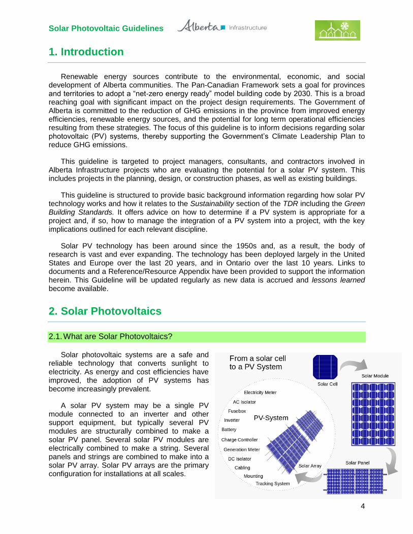
Solar photovoltaic systems are a safe and reliable technology that converts sunlight to electricity. As energy and cost efficiencies have improved, the adoption of PV systems has become increasingly prevalent.
A solar PV system may be a single PV module connected to an inverter and other support equipment, but typically several PV modules are structurally combined to make a solar PV panel. Several solar PV modules are electrically combined to make a string. Several panels and strings are combined to make into a solar PV array. Solar PV arrays are the primary configuration for installations at all scales.

Solar Photovoltaic Guidelines
5
PV Covered Bike Lane3
BIPV Roof Shingles7
BIPV Window Application 8
Wearable PV 4
PV Integrated into Public Art 6
Free Standing PV Array 5
Solar PV technology can be applied in numerous ways and at varying scales, from that of a handheld device to utility sized PV farms. The scope of this Guide is specific to Alberta Infrastructure facilities, where PV arrays are primarily installed on top of a flat roof or onto a wall. Building Integrated Photovoltaics (BIPV), whereby PV cells or modules are incorporated into building cladding such as in wall assemblies, roof shingles, or windows, may also be appropriate for some projects. Some considerations for determining if an attached PV array or a BIPV array is most appropriate include building configuration, orientation, available roof, wall and ground area, cost, system efficiency, and the overall goals of the project.
The solar PV technology selected and the type of design (attached or building integrated) should be based on both the funding available and the project’s charter intentions, as these selection decisions will affect the PV system cost and energy generation.
Solar PV system components and labour 2

Solar Photovoltaic Guidelines
6
Solar Photovoltaic Technology
Commercially-available cell technologies primarily include mono-crystalline and multi-crystalline silicone (c-Si). Additionally, there are emerging technologies of thin-film amorphous silicon (a-Si, TF-Si), cadmium telluride (CdTe) and copper indium gallium selenide (CIS/CIGS).
The table below compares the performance and benefits of each technology as published on the Energy Informative website as of September 2013. Note that while mono-crystalline panels are the most efficient option in both efficiency and size, they are also the most expensive option.
Mono-crystalline
Poly-crystalline
Amorphous CdTe CIS/CIGS
Typical module efficiency
15-20% 13-16% 6-8% 9-11% 10-12%
Best research cell efficiency
25.0% 20.4% 13.4% 18.7% 20.4%
Area required for 1 kWp
6-9 m2 8-9 m2 13-20 m2 11-13 m2 9-11 m2
Typical length of warranty
25 years 25 years 10-25 years
Lowest price 0.75 $/W 0.62 $/W 0.69 $/W
Temperature effects
Performance drops 10-15% at high temperatures and is increased 18-25% at low temperatures.
Less temperature resistant than monocrystalline
Tolerates extreme heat
Relatively low impact on performance
Additional details
Oldest cell technology and most widely used
Less silicon waste in the production process
Tend to degrade faster than crystalline-based solar cells
Low availability on the market
Modified from: http://energyinformative.org/solar-cell-comparison-chart-mono-polycrystalline-thin-film/
Consider durability and available warranties when selecting the appropriate PV modules for a project. The long-term performance and warranty should be assessed in accordance with the project’s charter and the client’s operational and maintenance requirements. Review PV module capacity, other electrical components (e.g. inverter), and installation processes for the entire PV system. Ensure existing (if applicable) and new elements are compatible, and that new or replacement parts are readily available.
Most Common Crystalline Cells 9 Flexible Amorphous Silicon Thin Film
10

Solar Photovoltaic Guidelines
7
2.2. Inverter Technology
The electricity generated by the solar PV panels is direct current (DC) while the electricity grid and building electricity are alternating current (AC). This requires the electricity to be inverted before it can be used in the building. There are two main types of inverters which have impacts on system performance:
String (central) inverter systems; and
Module-Level Power Electronics.
String (central) inverter systems are the solar PV connected in series. The total circuit voltage from the string is delivered to a single inverter. String Inverter Systems are suited for projects where the solar PV is installed along a single plane without any shading as the circuit connected to the central inverter will only produce as much electricity as its least productive panel.
Module-Level Power Electronics (MLPE) are installed on each individual panel, which avoids the scale of the power reductions from shading. This results in a slight increase in power production; however, there is an associated increased initial cost. Additionally, these systems do allow individual monitoring of the PV panels throughout the installation. The increased electronics can experience higher failure rates and increased cost for replacement; as such, MLPE technology is only recommended where shading is present.
The MLPE technology can be further broken down into the following:
Power optimizers convert DC to DC at each individual panel and still require central
inverters. These are less expensive than the micro-inverters with simpler rooftop wiring
and higher durability.
Micro-inverters convert the DC to AC at each individual panel and do not require circuit
inverters. The central inverters that are required for both power optimizers and string
inverters have maximum warranties of 10-12 years while the warranties for Micro-
Inverters are typically 25 years.
For more information, ELSEVIER SciTech Connect presents the differences of the technologies in the following article:
The Essential Differences of String Inverters, Microinverters, and Power Optimizers http://scitechconnect.elsevier.com/differences-string-inverters-microinverters-power-optimizers/

Solar Photovoltaic Guidelines
8
3. Designing with Solar Photovoltaic
Installing a PV system in a facility requires a thorough analysis of the overall goals of the project, potential opportunities, and potential risks. While it is recommended that the feasibility of the site’s solar potential and building requirements for the solar PV array are considered in the initial stages of design, projects at all stages of development are encouraged to establish the viability and funding requirements of the solar PV system. Additionally, a community consultation may be prudent, depending on the size and location of the project.
For new building projects and major renovations past the initial design stages, a structural review and a preliminary feasibility study will be required to assess the viability of moving forward with a PV system. Existing buildings also need to include a similar structural review for viability, but a less rigorous feasibility review should suffice. Consider the following questions:
Can the current designed structure handle the new loads from PV arrays, wind, snow,
etc.?
What is the age and condition of the roofing system?
Can a large enough PV array be provided to meet the client’s expectations and the
project’s charter?
Will the solar PV system and any required structural and design alterations have an
acceptable return on investment (ROI) in electricity cost savings, operations and
maintenance, emission reduction and social engagement?
Once these questions have been answered in the affirmative, the project team can begin the more rigorous process of preparing for the PV system installation. For Alberta Infrastructure projects, these considerations are described in the next few sections.
3.1. Technical Design Requirements
All of requirements of the Alberta Infrastructure owned or supported projects, including solar PV projects, must meet the TDR. There are some beneficial overlaps between solar PV and the TDR, including the Sustainability section and the certification requirement within the Green Building Standard. As the incorporation of solar PV systems into Alberta Infrastructure projects is relatively recent, some conflicts between the TDR and the Solar Photovoltaic System Guidelines may emerge. Contact Technical Services Branch for assistance.
3.2. Sustainability
The Government of Alberta is committed to incorporating sustainable strategies into its facilities, including the reduction of GHG emissions and long-term environmental stewardship.
The Green Building Standard provides definitions of Tier 1-4 based upon the budget and scope. All projects are to strive to incorporate sustainable strategies, and many may be appropriate for a PV system. The TDR Appendix "G" Excel Spreadsheet includes the Net Zero Energy Target Tool used to approximate the amount of energy consumption and PV energy generation required to achieve a net-zero balance of energy. This tool is recommended for initial solar PV system assessments.
TDR Appendix "G" Excel Spreadsheet and the Net Zero Energy Target Tool: http://www.infrastructure.alberta.ca/992.htm

Solar Photovoltaic Guidelines
9
During the early planning stages, the team should be aware that the building type and number of storeys are significant factors to consider when designing for the incorporation of solar PV systems.
From the National Renewable Energy Laboratory (NREL), the number of storeys that a building affects the potential to achieve net-zero energy. One and two story buildings have a greater potential to achieve a net-zero energy target than taller buildings based on the increased building envelope to floor area ratio.
For further information, please see the following articles:
Assessment of the Technical Potential for Achieving Net Zero-Energy Buildings in the Commercial Sector. http://www.nrel.gov/docs/fy08osti/41957.pdf
3.3. Leadership in Energy and Environmental Design
The TDR outlines the commitment to achieve Leadership in Energy and Environmental Design (LEED) Silver certification and the particular mandatory LEED credits for applicable AI projects. The use of renewable energy such as solar photovoltaic (PV), solar thermal, wind, bioenergy, and hydroelectricity may be used towards the “Renewable Energy Production” and “Optimize Energy Performance” credits.
Renewable energy production projects earn credit based on the percentage of total building annual energy cost that is supplied by the on-site renewable energy system.
Note that for LEED Operations and Maintenance, the credit is an overlap of renewable energy and carbon offsets; carbon offsets are awarded points on the basis of 25% purchased energy.
For Optimize Energy Performance, Option 1, the equivalent energy cost that is offset by the on-site renewable energy system is deducted from the project's annual energy cost, thus improving the project's building performance rating compared to the Appendix G baseline and potentially increasing the number of points earned under this credit.
The points achieved from renewable energy do not replace any normally targeted points. The project should be able to achieve minimum LEED Silver certification as defined in the TDR before counting the points achieved from renewable energy. The building design must meet the minimum number of points for Energy and Atmosphere - Optimize Energy Credits noted in the TDR before adding points for renewable energy systems to the energy cost savings. It is encouraged that projects installing solar PV consider targeting LEED Gold certification.
Points Available
1 2 3 4 5
LEED BD+C (NC) 1% 5% 10%
LEED O+M 1.5% 3% 4.5% 6% 7.5%
LEED ID+C 1% 3% 5%
NOTE: The LEED credits targeted for incorporating a solar PV system, MUST NOT be
part of the minimum 50 points to achieve the REQUIRED LEED Silver Certification. Solar PV could help to achieve the Gold level of LEED Certification.

Solar Photovoltaic Guidelines
10
3.4. Zero Carbon
Currently the electricity grid in Alberta, is about 10% renewable. The Alberta Climate Leadership Plan establishes that by 2030 the electricity generated in this province will be 30% renewable and 70% natural gas. While this will greatly reduce the GHG emissions associated with electricity generation, there are significant offsets that must be achieved compared to buildings in British Columbia or Ontario where the grid electricity is less carbon intensive.
The Zero Carbon Building – Design (ZCB-D) certification, released by the Canadian Green Building Council (CaGBC) includes requirements of the Zero Carbon Balance, Net Zero Transition Plan, Install Onsite 5% Renewable Energy, and Achieve Thermal Energy Demand Intensity Target. For the installation of Solar PV, while 5% onsite renewable energy is the minimum of the standard, exceeding 5% while reducing overall energy consumption should be considered.
Zero Carbon Building Standard
https://www.cagbc.org/cagbcdocs/zerocarbon/CaGBC_Zero_Carbon_Building_Standard_EN.pdf
3.5. Durability
Alberta Infrastructure facilities strive for durability, maintainability and longevity with reasonable operations and maintenance protocols. Installing a solar PV system must not compromise this objective, but rather enhance it. The design and installation of a PV array should address the following:
Impact to areas where the PV modules are physically connecting to or contacting the
building on the roof or the exterior envelope;
Additional load on the structural system;
Effects of wind: movement of modules and abrasion of roof membrane;
Effects of snow accumulation;
Electrical load requirements, connections and systems;
Maintenance; complexity of operating the system, service agreements, extra training,
software monitoring systems;
Frequency of PV system and roof (or mounting surface) inspections;
Warranties and performance; longevity of system components; and
Long term maintenance costs (need for Life Cycle Costing).
3.6. Community Engagement
The opportunity to install a renewable energy system like solar PV goes beyond the
generation of electricity for a particular facility. As a best practice, it is a way to engage the
community for their input, address their concerns and educate them about solar PV and the
sustainable strategies the Government of Alberta is supporting in their public projects. The local
and broad public community can be informed about these projects through online and public
face-to-face engagements as coordinated by the project team and as described in the project
charter. Community interaction should be a goal of all solar projects to determine optimal
outcomes for all stakeholders.

Solar Photovoltaic Guidelines
11
NOTE: The calculation in the Net Zero Energy Target Tool is based on the Edmonton
solar potential of a solar PV array facing south and tilted at latitude minus 15°. This should be adjusted for each project based on location. The solar potential is based on the capacity density of as solar PV array, estimated at 0.0606 kW/m2, including clearance and pathways around the array. If higher or lower array capacity density is expected, the PV system is at a different tile or azimuth angle, the project type has a different energy use index (EUI) or is located in in a different climate zone, adjust the numbers and provide the justification.
4. Initial Assessment
The project team, led by the Project Manager (PM), has to answer the following initial basic questions:
Can the current designed structure handle the new loads from equipment, snow, etc.?
What is the age and condition of the roofing system?
Can a large enough solar PV array be provided to meet the client’s expectations and the
project’s charter?
Will the solar PV system and any required structural and design alterations be cost
effective in regards to its return on investment (ROI) in electricity, operations and
maintenance, and GHG emission reduction?
STEP 1
Confirm with local bylaws and authorities having jurisdiction regarding the solar PV
configurations that are permitted.
STEP 2
Use the Net Zero Energy Target Tool in the Appendix G Checklist, inserting the project areas and information. The RETScreen Expert software can also provide solar energy analysis information.
http://www.infrastructure.alberta.ca/992.htm
The assessment fields are generated with only three area inputs, circled below (unless density / energy use index / climate zone adjustments are required):

Solar Photovoltaic Guidelines
12
Once the project areas have been inserted, the four Net Zero Analysis percentage results will be generated and the cells will change colour relative to the feasibility of achieving net- zero energy. Note that estimates of snow cover need to be included in any energy generation modelling.
Example 1
Green results (75-100%+): project can generate a significant amount of the project’s estimated energy consumption. From this result, proceed to the next level (Step 2) of assessment.
Example 2
Orange or yellow results (<50%): double-check the project’s energy index and densities. Is there anything further to be adjusted on the roof or ground to improve the solar PV system? Will this PV system install still meet the project’s charter or the client’s expectations?
Example 3
Light green or yellowish green results (55-70%): the project has potential to reach net-zero energy. Discuss these results with the client and the design team, and determine if these results still align with the project’s intentions; further design adjustments and innovation may be required.
Before proceeding to the next stage of assessment, thoroughly review applicable zoning bylaws to confirm that solar PV is permitted. Consider the impacts of future neighbouring construction (e.g. shadows cast by a tall development) – confirm before proceeding. A shading study can be helpful.
For reference for other regions in Alberta, see:
Photovoltaic and solar resource maps https://www.nrcan.gc.ca/18366

Solar Photovoltaic Guidelines
13
STEP 3
Develop preliminary Life-Cycle Cost estimates. The following tools are useful resources:
NREL Distributed Generation Renewable Energy Estimate of Costs, and
https://www.nrel.gov/analysis/tech-lcoe-re-cost-est.html
Harvard Life Cycle Calculator.
http://energyandfacilities.harvard.edu/green-building-resource/green-building-tools-
resources/life-cycle-costing

Solar Photovoltaic Guidelines
14
5. Solar PV Feasibility Study
If the project intends to proceed with solar PV, a feasibility study is required to demonstrate the appropriate price of the energy generated. For a new building project, a renovation project, or a retrofit of an existing building, a solar PV feasibility study should be completed and demonstrate the measurement and modeling of solar PV generation, building type and program, and the financial implications. The team can now proceed to the next step:
STEP 4
As your starting point, go to the Solar Ready Checklist from the NREL:
Solar Ready Buildings Planning Guide http://nrel-primo.hosted.exlibrisgroup.com/Pubs:PUBS:NREL_PUBSd2055aa8-bad4-e411-b769-d89d67132a6d
The deliverables checklist must be adapted to suit the project’s climatic zone and the particulars of the project as defined by the project team and charter. The feasibility study should present multiple implementable options for the solar PV installation, demonstrating a thorough exploration of possibilities. These options are to be presented independently, along with interaction between the options where cost savings would reside.
The feasibility study may be compiled by an in-house team or by consultants; however, the whole team should be involved. The whole team may include but is not limited to: clients, design consultants, solar consultant, project management team, cost consultants, user groups, and the solar supplier/installer, if possible. As mentioned previously, it may also involve some members of the community where deemed appropriate.
The Solar PV Feasibility Study should consider and include the following:
Initial Assessment: The findings from the Net Zero Energy Target Tool, as described in
Step 2, and this should mention any climate, energy use index or capacity density
adjustments, etc. that the team used.
Building Description: The type, program, site, neighboring buildings and
developments, applicable bylaws, roof slopes, building azimuth orientation, local climate,
and the project’s current stage of development, and how these aspects influence the
energy requirements.
Measurement and Modeling of Solar Generation: Working with the latest design of
the facility, model the options where solar PV array could be installed and supported,
and what might be the optimal design to maximize the electricity generation.
Building Solar PV Design Requirements: Define the specific electricity generation and
energy needs for the facility to achieve net zero, and the project’s particular targets if not
net zero.
Financial Requirements: What the capital costs are for each option, and the life-cycle
costs considering long term maintenance, repairs, effect on the roof or wall maintenance
and replacement, or building envelope if a PV array is integrated into the exterior walls.
NOTE: The estimated GHG emission reductions, as well as the intangible benefits, such as
job creation, environmental education and awareness, should also be expressed in the study.

Solar Photovoltaic Guidelines
15
NOTE: The final solar potential model deliverable, as a report, drawings, and/or BIM file,
must be signed & sealed by the overseeing professional of record (see permit requirements).
5.1. Building Description
Briefly describe all aspects of the project’s parameters, objectives, and design intentions. Elaborate on and emphasize any aspects that will affect the PV system, or conversely where the PV system will affect the building or life safety systems. Some considerations include:
Operational hours: Building projects such as a two storey school that is not open at night
or all summer require less heat during evenings and no air conditioning during the
summer;
Shading: Tall trees, buildings nearby, or an urban site that may have an existing or
future tall building development may cast shadows over the PV array and reduce the
generation;
Wind load: The site’s micro-climate may affect the solar PV array in various ways. A site
that is particularly windy may add extra wind loads to the roof installation, which will
affect the amount of ballast on a ballasted solar PV array;
Orientation of the building: Predesign and early design phases are the optimal time to
consider a solar PV array. For a project that is past the design stage, turning the building
to maximize the sun’s exposure could incur significant cost in redesign fees and
compromise the project schedule;
Roofing: The roof-mounted PV array may affect the roof membrane or the roof warranty
(more on roofs in Section 6.4 Building solar PV System Design Requirements); and
Other: Assess the potential risks to building operations, critical or sensitive activities or
specialized equipment.
5.2. Measurement and Modeling of Solar Potential
Building and site modelling is required to identify the solar potential of the proposed project based on location, structure, orientation, and weather. Existing building projects will require on-site measurement of the location and size of all rooftop mounted equipment, and to identify and measure any shadow-causing obstructions. It is recommended that new building projects include on-site measurements to identify potential shading and the effect of the architectural design.
The architectural design model and the energy model should be synchronized with the solar potential model. Most current software programs to run energy models will demonstrate and analyze the solar potential. The prime consultant or engineer is responsible for the design and energy model coordination with the solar study.
The solar potential study should identify the azimuth (orientation), angle and tilt angle of the solar PV modules, demonstrating the optimal solution for the intended design and operation of the building, including any appropriate explanations for non-apparent intentions or deviations from due south or similar. This study should calculate the yield of the solar PV system, which is the ratio of the annual energy generation divided by the rated PV array capacity. The drawing package and (where applicable) renderings, provided for design review submission, are to clearly exhibit the intent of the solar PV design.

Solar Photovoltaic Guidelines
16
5.3. Building Solar PV System Design Requirements
The specific system design requirements are to be defined by the whole project team through collaborative analysis and discussions. The team includes the clients, the user group, facility maintenance and engineering staff, energy and design consultants, and the project managers. If the contractor and/or the supplier are available, then include their valuable input. It is recommended that the project assesses both the initial solar PV system to be installed, as well as determine if and where a future solar PV system is applicable.
When developing the solar PV system design requirements all disciplines should be involved to cover all aspects of the facility that may be impacted. This pertains to the architectural, structural, roofing, electrical, and mechanical design components. The development must factor in the full life-cycle cost. The summary of the design requirements is to be included in the feasibility study and elaborated upon as the design develops. The particulars of each of these disciplines are explained in the following sections.
Architectural
The architectural team, and typically the prime consultant, will usually be responsible for the coordination of all aspects regarding the solar PV system design and delivery of the coordinated design documents for bid and construction and installation for new buildings and modernizations. Architectural design considerations include:
Aesthetics of the PV array on the building, the roof, or the ground;
Locations of solar PV sub-arrays including roof, ground, parking canopy, awning, and
integrated into windows and cladding;
Impact on the community and adjacent sites;
Review of the local zoning bylaws and permitting (see Section 7);
The building orientation, where shading from the surroundings is understood and
considered;
Location of and shading from all the rooftop equipment (mechanical units, fans,
pipelines, electrical and telecom conduit, roof drains, plumbing stacks, curbs, roof
anchors and lifelines), penthouses and parapets by the project team;
Roof design for sloped roof or flat roofs and access for maintenance;
Thorough review of existing conditions when working with an existing building; confirm
the roof structure, roof membrane and envelope assembly to prepare for a PV array
installation;
Sun exposure and shadow studies;
Wind study including the affect of this building on wind uplift, particularly in an urban
setting or with a tilted solar PV array;
Coordination of solar PV systems with structural, mechanical, electrical, civil, and
landscaping;
Connection of the PV array to the structure: structurally-fastened, ballasted, hybrid, or
wall attachment configuration. This includes the roof penetrations, required curb details,
and dismounting or re-mounting connections;
Coordinate the program areas directly under the solar roof top arrays to be cognisant of
“riskier” program areas, such as gymnasiums, computer systems, electrical room; and

Solar Photovoltaic Guidelines
17
Sloped Roof mounted PV array, mechanically fastened 12
Roof mounted tilted PV array using ballasts 11
NOTE: For existing buildings looking at solar PV, the condition and age of the roof
membrane must be fully assessed. This is done to coordinate a plan for the roof membrane replacement, in conjunction with the PV system installation. If the replacement is expected within the next 10 years, it is highly recommended and cost effective to schedule the solar PV system install when the roof is replaced.
Safety concerns: during construction, daily operations of facility, maintenance of rooftop
equipment, emergency responders, and PV system. Refer to CSA in Appendix A, and
the Occupational Health and Safety website.
Structural
For mounting a solar PV array on a roof, the major structural decision for the project team is whether to structurally-fasten the array racking to the buildings roof structure, that could mean roof assembly penetrations, or to use array racking that uses ballast stones (to weigh down the solar PV array). Due to cost and ease of installation, most PV systems being installed on commercial buildings are of ballasted design. This however affects the roof warranty type that is available, and there are concerns regarding the extent to which the ballasted system will move on the roof.
Structural systems can be designed to accommodate almost any building and roofing system. A structural engineer is required to coordinate the design for the appropriate support and connections to the PV system. This includes the calculation of gravity and live loads including snow and wind uplift. The wind loads may be compounded depending upon the tilt angle and height of the solar modules, and their proximity to building’s edge. Overloading of the roof or the mounted racking system may result in failure or collapse.
Several structural design elements must be considered for any solar PV array. The quality and durability of the PV system design is heavily dependent on the structural consultants, and all of the design consultants.
The structural considerations for a solar PV array installation include:
The array weight, wind deflection, and vibration on insulation, which leads to pooling,
moisture drive, and deflection factors;
Whether the PV system be structurally fastened to the building structure utilizing roof
curbs with roof penetrations through the roof membrane;

Solar Photovoltaic Guidelines
18
The amount of movement of the array that can be expected when implementing
ballasted racking;
Co-ordination with the manufacturer of the ballasted racking system;
Affect of the building and surroundings on the wind uplift, particularly in an urban setting
or with tilted PV arrays; a wind lift analysis should be conducted for all roof top
installations;
Independent and connected movement of the PV panels;
The existing conditions when working with an existing building, including the roof
structure and the capacity for additional loads;
Durability of installed solar PV arrays and roofing membranes over 10, 20, or 50 years;
consider the ballasts moving over the roof membrane for 10 years; and
Installation procedures to prevent damage to a new or existing roof.
Further testing for the wind-induced effects on installed solar PV systems in Canada is planned. The height and tilt of the module over the roof could result in substantial uplift wind forces. Calculating the PV system load and the building load will NOT equal the total load until all wind loads, including uplift, are accounted for. To help address wind uplift, it is recommended PV arrays be placed several feet away from the roof edge; ARCA and CSA call for a 3-meter perimeter.
It is recommended by NREL that the weight of a PV is between 15 and 29 kg/m2 (3 and 6 lb/ft2). See the American Society of Civil Engineers (ASCE) Minimum Design Loads for Buildings and Other Structures ASCE/SEI 7-05, to calculate the roof loads. Refer to the following guideline:
http://ascelibrary.org/doi/book/10.1061/9780784412916
Roofing
There are challenges in achieving a high performing, water tight, and well insulated roof that meets the needs of a roof-mounted solar PV array. The roofing design decisions should be thoroughly discussed with the consultant team, and the client group.
There are three attachment options for a roof mounted solar PV array, as previously mentioned in the structural section:
Ballasted array sitting on the roof held down by the weight of the ballast stones;
Structurally-fastened array that is attached to the roof structure; and
Combination of ballasted and structurally-fastened.
Ballasted Array
For the ballasted array, the affect of the solar PV system on the primary membrane is determined by the membrane thickness. This needs to be accounted for in the preliminary design stages. The ballast anchors will move and scour on the surface of the roof, potentially scraping the roof membrane. There are ways to provide additional protection for the membrane, such as adding another layer of membrane, or providing sleepers for the racking. Another suggestion is to use concrete pavers, placed on a minimum 25mm thick layer of type 4 insulation that is situated so that drainage is free to flow around the pavers. Alternatively, an additional ply of mineral surfaced cap sheet can be applied to the primary membrane where all the racking will be placed.

Solar Photovoltaic Guidelines
19
NOTE: The solar PV array racking connections and curb flashing details if applicable,
should be adjustable or easily removable as appropriate to accommodate access for maintenance and the potential addition or removal of any necessary rooftop equipment.
NOTE: In the life-cycle costing analysis, consider the maintenance and repair costs for
each option.
The method of mounting conduit on the roof should also be considered to reduce potential damage and protect the primary membrane.
Structurally-Fastened
Securing the PV racking to the structure will resolve the potential issues with the ballasted approach which are movement and scouring effects on the roof membrane. Arrays that are attached to the structure can be accommodated by installing posts, sleepers or curbs that are then integrated into the overall roof composition.
It is recommended that all attachment points to the roof structure are curbed, encapsulated by non-flexible, rigid conduit-style sheathing, and flashed “doghouse” style. The connection’s detail should be to the vertical face of the curbs at min 200mm above the roof’s finished surface. The raised and side connection will minimize exposure to snow and water and therefore reduce risk of deterioration and leaks.
This method will likely cost more to install, while potentially save costs for maintenance and repairs. Coordinate this in the life cycle costing analysis.
Roofing Considerations
The roofing assembly in most cases, will be the most significant design element to address for a roof-mounted solar PV array. The roof is ideal for solar gain, however, there are several design items to consider. Selected synopses of these considerations include:
Ballasted racking system or structurally-fastened via roof curbs or posts;
Parallel mounting or tilted modules;
Roof venting, HVAC units, pipelines, conduit, plumbing stacks and other roof projections;
Roof drains, and roof drainage management;
Roof slopes, dormers, clerestories, solar tubes, skylights;
Snow loads and drifting;
Wind loads and wind uplift conditions;
Type and thickness of membrane; the additional of a protective strip or layer;
Reflectance: Colour of the membrane should be light or white;
Access to the roof for maintenance, inspection and repairs, and emergency responders;
and
Appropriate clearances for access to roof top equipment, including the PV modules
themselves.

Solar Photovoltaic Guidelines
20
NOTE: It needs to be recognized that the installation of roof mounted solar arrays MAY
reduce the Alberta Roofing Contractors Association (ARCA) warranty OR it may be VOIDED
all together if the ARCA requirements are not met.
Higher rooftop temperatures can reduce the PV system's energy generation. It is therefore recommended to specify lighter colour membranes. As shown in the table in section 2.2, the module efficiency of mono-crystalline solar PV modules ranges between 15%-20%. Industry consultation has identified that this efficiency has been increasing by between 0.5%-1% per year; however, the PV system energy generation is reduced by slightly less than 0.5% for every 1°C increase in PV cell temperature above 25°C.
Close co-ordination is recommended with racking manufacturers to determine where to install PV modules with respect to perimeters and corners where higher wind events tend to occur. Consider spacing rows or columns of modules far enough apart to allow access to rooftop equipment and drains and to allow for periodic maintenance to the overall roof area. This is also a safer approach for maintenance workers. See the ARCA bulletins for recommended distance clearances.
ARCA has issued recommendations to cover the effects and ongoing maintenance requirements when a solar PV system is installed on a roof. This includes the effects on access, water, flood, fire, and maintenance. For rooftop installations, the CSA guideline should be reviewed and adhered to in order to ensure that buildings address the safety concerns and performance demands. The marriage of these two aspects is the most critical to a successful solar PV system.
Warranty Considerations:
Currently, Alberta Infrastructure requires all new roofs to meet ARCA standards. Recently, ARCA has issued their specific requirements for roof-mounted PV equipment. These requirements coincide with the CSA guidelines and reflect both practical maintenance objectives as well as safety concerns. Adherence to these requirements will help ensure your project will obtain a warranty. Refer to ARCA’s website for more comprehensive information:
https://www.arcaonline.ca/sites/default/files/AB-2017-06%20Roof%20Mounted%20Photovoltaic%20Safety.pdf
Roof-Mounted Photovoltaic Equipment Requirements for ARCA Warranty projects include:
Minimum 3000mm (10’) clearance around perimeter of roof;
Minimum 1200mm (4’) clearance between rows of PV arrays;
Minimum 1200mm (4’) clearance at all roof penetrations;
Minimum 300mm (12”) clearance between the roof membrane and the underside (lowest
point) of photovoltaic equipment;
Maintain minimum drainage slope of 2%;
PV equipment to occupy a maximum of 50% of the roof area (note: CSA allows for more
than 50% if appropriately designed by structural engineer);
Only rack-mounted PV systems secured to the roof structure;
It is worth consideration to allow roof warranty issues to be addressed prior to the installation of solar. Most issues with any new roof are captured and repaired through the ARCA warranty by the 2nd annual inspection.

Solar Photovoltaic Guidelines
21
Electrical
The electrical engineering consultant should have solar PV system expertise, or engage a specialized consultant for this scope of work.
An electrical engineer will be responsible to design and co-ordinate the solar PV system and all of the appropriate electrical connections to the facility’s electrical panel boards and to the Wires Service Provider (service utility). They will identify the project’s expected electrical energy consumption based upon the area program, client requirements, and the projected future electrical energy needs.
The PV system electrical design will include the capacities and connections between current and potential future PV systems, facility panelboards (considering bus and breaker capacity and locations, including the main service panelboard and any sub-panelboards), inverter locations, conduit runs, metering for energy generation and the electrical grid. The electrical engineer will determine the estimated reduction of grid-supplied electricity due to the proposed solar PV system. The electrical PV system design could also potentially showcase or display the energy activity for educational and promotional purposes.
Electrical work will be completed in compliance with the most current versions of the appropriate Building and Electrical Codes. Both professional electrical consultants and installers are well aware of the safety requirements and the ongoing development of Safety Codes and regulations surrounding the growing solar electricity generation industry. Refer to CSA document Section 8 of Solar Photovoltaic Rooftop-Installation Best Practices Guideline below and in the Reference Section 11 of this document. Refer to:
Canadian Standards Association (CSA Group). SPE-900-13. http://shop.csa.ca/en/canada/renewable-thermal-energy/spe-900-13/invt/27035492013
Canadian Standards Association. Canadian Electrical Code, Part 1. http://shop.csa.ca/en/canada/landing-pages/2015-canadian-electrical-code-part-i-/page/cecode2015
Solar Ready Buildings Planning Guide http://www.nrel.gov/docs/fy10osti/46078.pdf
The electrical design considerations for a solar PV array installation include:
Total current and future electrical load requirements for the facility;
Optimal solar PV system energy generation and how to achieve it;
Design, selection, and co-ordination of all solar PV system components;
Coordinated electrical connections between PV system and facility electrical systems,
including fire alarm, and emergency shut offs;
Advanced metering and tracking software, for total electricity consumption and for solar
electricity generated;
Safety measures by code and enhanced safety features; for fire prevention, waterproof
protection, and for maintenance workers;
Thorough review of existing conditions when working with an existing building; confirm
the panelboard electrical capacity;
Conditions and agreements with the Wires Service Provider;
The placement of electrical and telecom conduit; and
The Micro-Generation Regulation (see Section 7).

Solar Photovoltaic Guidelines
22
Mechanical
The mechanical engineering consultant will be responsible to assist with the solar PV system design where it affects rooftop venting and rooftop mechanical units and/or penthouse. The mechanical engineer will have to design and coordinate the following:
Roof venting is grouped to streamline access, or provide side vents out through walls;
Roof drains are coordinated with PV arrays, architectural, and civil where necessary;
Location of the mechanical units other than the roof top;
The placement of rooftop mechanical units and gas pipelines should be optimized for
solar PV; and
The impact on the energy model as appropriate.
5.4. Safety
Always, safety in Government of Alberta facilities is a top priority. This includes safety during construction for labourers and PV system installers, and throughout the life of the building, for maintenance workers, emergency responders, staff and the user groups of the facility. The effects on the fire and life safety systems include combustibility, drainage, and natural hazards. The solar PV systems may affect all of these risks if not properly designed and coordinated.
Safety concerns to be discussed and addressed include:
The selection of solar PV components that meet or exceed CSA standards or equivalent
safety testing and performance;
That fall protection strategies are implemented, during construction and installation,
maintenance events and for all other roof access;
Electrical conduits and all electrical components are well protected from the
environmental elements, snow, rain, standing water on the roof;
Allowance for sufficient clearances between arrays to access for maintenance,
inspections, drainage;
Plans for regular roof inspections, and design PV array with roof maintenance and
inspections in mind for optimal durability, consider safety of maintenance staff and
contractors;
Design for appropriate drainage on the roof to avoid ponding; including the design for
drainage redundancy;
Meeting with the local Fire Marshal or Chief Administrator to discuss the roof PV system
and any safety recommendations they have for fire prevention and the safety needs of
first responders;
Consideration of installing a roof video camera for remote monitoring;
Provision of appropriate secure access to the roof;
Provision of appropriate warning signage for maintenance workers; and
Plans for bird and vermin deterrence.

Solar Photovoltaic Guidelines
23
For more information on safety requirements refer to the OHS Act, Alberta Fire Code and Alberta Building Code:
OHS Act, Regulation and Code https://work.alberta.ca/occupational-health-safety/ohs-act-regulation-and-code.html
Alberta Fire Code 2014 https://www.nrc-cnrc.gc.ca/eng/publications/codes_centre/2014_alberta_fire_code.html
Alberta Building Code 2014 https://www.nrc-cnrc.gc.ca/eng/publications/codes_centre/2014_alberta_building_code.html

Solar Photovoltaic Guidelines
24
6. Financial Requirements
The solar PV system feasibility study must have the appropriate cost estimates for the initial purchase and installation of the PV system, as well as all of the associated long term maintenance and operations costs. This life-cycle costing (LCC) analysis can be relatively simple, provided the client and user group both understand the cost risks.
While the determination on whether to include solar PV is not hinged on the financial payback, it is prudent to assess and identify the targeted cost for the PV system with its predicted payback. A financial analysis for each solar PV system option should be completed. It is recommended that LCC be employed for the financial analysis to quantify the life-cycle impacts on GHG, energy costs, and maintenance costs.
6.1. Life-Cycle Cost Analysis
STEP 5
Complete the full LCC analysis for both the financial and the associate GHG emissions including the capital and maintenance costs. Generally, there will be a scope of work description pertaining to the construction or roofing scope, and there will be a scope of work for the solar PV installer.
Solar PV capital and maintenance costs
Pricing for the options presented should be obtained through the Procurement Branch of Alberta Infrastructure. The solar PV consultant should provide a reasonable payback analysis for the PV system, and can advise on long term maintenance and repair costs over the building life-cycle. For the LCC analysis, the maintenance costs for solar PV system should include likely replacement and upgrading costs of any or all system components.
There are potential additional maintenance costs for inspections or other effects of the roof or PV system design (e.g. Inspector has to check under each PV module at just 100mm high). Any additional safety measures or equipment associated with the PV system maintenance and inspection should be included in the costs.
Roof capital and maintenance costs
Obtain cost estimates on the impact of the preferred options from the solar PV consultants. These estimates should include:
Capital costs for the roof curbs, any structural augmentations, and the electrical
infrastructure to accommodate the solar PV system; and
Roof maintenance costs, accounting for a valid ARCA warranty or no warranty, and the
costs to remove the solar PV array to properly repair the roof.
It is important to understand that PV installers cannot inform the LCC for the roof capital costs and the potential impacts on the long term roof maintenance costs.

Solar Photovoltaic Guidelines
25
NOTE: It is estimated by ARCA that a typical major repair to a roof will cost approximately
$10,000; generally, this is covered under warranty. A solar PV system on a roof may have to be removed before the roof repairs could happen. This removal and re-install would not be covered by ARCA warranty, and this is estimated at $100/m2.
Electricity cost and GHG savings:
The utility costs for electricity in the LCC should reference the agreements that are in place, the Green Power purchased, the escalation rates, and the payback period. The estimated savings from the electricity utility provider based on:
Alberta Electric System Operator, “Transmission Rate Impact Projection Workbook,” June 2014 http://www.aeso.ca/transmission/30685.html
The estimated GHG savings should refer to the electricity grid displacement and grid usage factors established by the Alberta Climate Change Office:
ESRD Carbon Offset Emission Factors Handbook http://aep.alberta.ca/climate-change/guidelines-legislation/specified-gas-emitters-regulation/documents/CarbonEmissionHandbook-Mar11-2015.pdf
It is recommended that project managers contact Energy Efficiency Alberta to inquire on the programs and incentives available. Refer to:
Energy Efficiency Alberta https://www.efficiencyalberta.ca/solar/
6.2. Operation and Maintenance
As there are maintenance costs directly associated with the operation of solar PV, the operation and maintenance (O&M) plan and pricing should be included in the feasibility study.
Other considerations to plan for include:
Regular roof inspections, and design the solar PV arrays with roof maintenance and
inspections in mind;
Appropriate clearances for maintenance workers and inspectors;
Fire risk from nesting birds and baring of wires; and
Cleaning of debris (blowing leaves, bird droppings, and garbage).
The effect of the recommended O&M plan should be consistent with the predicted costs and savings. It is recommended that the plan include:
In-house training with detailed drawings and operation and maintenance manual for its
operation and maintenance; and
Identification of a dedicated person or contracting of the PV system installer for specific
period of time (suggested at least 10 years).
The plan from the NREL report Best Practices in Photovoltaic System Operations and Maintenance, 2nd Edition is included in the Appendices for this section.

Solar Photovoltaic Guidelines
26
7. Permits and Compliance:
All projects that are intending to implement grid-connected solar PV systems are required to be interconnected to the electrical grid of the Facility’s Wires Service Provider using either the Electric Utilities Act (EUA) or the EUA’s Micro-Generation Regulation (MGR). The EUA and the MGR should be reviewed at the beginning of the project by the consultant team. The MGR describes what is “micro-generation” and when a solar PV system is eligible to be a “micro-generation generating unit”. The graphic below illustrates the differences between a small and large scale micro generators and a distributed generator (commercial generation):
Micro-generator
Small micro-generator Large micro-generator
Load limitation Array can supply 100% of aggregated load’s yearly demand (maximum)
Array can supply 100 % of aggregated load’s yearly demand (maximum)
Relevant Regulation
Micro-Generation Regulation Micro-Generation Regulation
Application Process
Micro-generation notice to distribution facility owner conflict resolution through AUC
Micro-generation notice to distribution facility owner conflict resolution through AUC
Compensation Net billing of retailer’s rate minus T&D-Not hourly (cannot benefit from peak prices)
Hourly pool price from AESO (can benefit from peak prices)
Up to four permits potentially need to be obtained for grid-connected solar PV systems depending on the municipality. Permit Description Typical
Responsibility Submittals
Development permit
Municipal zoning and neighbour-relationships
Architect or PV consultant
Architectural drawings submitted to the municipality
Building permit
Alberta Building Code and structural safety
Construction manager or PV consultant
Structural drawings submitted to the municipality
Electrical permit
Canadian Electrical Code and electrical safety
PV installer Electrical drawings submitted to the municipality of the designated electrical inspection company
Grid-connection approval
Safety, electric power quality and electricity distribution system operation
PV consultant or PV installer
Site plans, electrical drawings, and data sheets (module and inverter) submitted to the Wires Service Provider
The development and building permit requirements vary with the municipality. Some municipalities don’t require them. Grid-connected PV systems always require electrical permits and grid-connected approvals.
150 kW 5 MW 10 MW
Summary of solar generation frameworks 13

Solar Photovoltaic Guidelines
27
Refer to these links for more information:
Interconnecting under the Micro-Generation Regulation:
Alberta Energy's explanatory website on micro-generation:
http://www.energy.alberta.ca/Electricity/microgen.asp
Alberta Utilities Commission's website on Micro-Generation:
http://www.auc.ab.ca/involving-albertans/micro-generation/Pages/default.aspx
Alberta’s Micro-Generation Regulation:
http://www.qp.alberta.ca/documents/Regs/2008_027.pdf
Alberta Utilities Commission's Micro-Generation Application Guideline:
http://www.auc.ab.ca/regulatory_documents/Reference/DistributedGenerationApplicationGuideline.pdf
Alberta Utilities Commission's Rule 024 governing micro-generation application steps:
http://www.auc.ab.ca/acts-regulations-and-auc-rules/rules/Documents/Rule024.pdf
Interconnecting under the Electric Utilities Act:
Alberta Utilities Commission's website on distribution-connected generation applications
http://www.auc.ab.ca/involving-albertans/getting-involved/Pages/ApplicationProcess.aspx
Alberta Electric Utilities Act
http://www.qp.alberta.ca/1266.cfm?page=E05P1.cfm&leg_type=Acts&isbncln=9780779785315
Alberta Utilities Commission's Rule 007 governing electric power plant application steps:
http://www.auc.ab.ca/acts-regulations-and-auc-rules/rules/Documents/Rule007.pdf
Installation:
There are legislated requirements for the installers of solar PV in Alberta. Refer to:
Photovoltaic Systems http://tradesecrets.alberta.ca/sources/pdfs/occupation_page_supporting/photovoltaic_info_sheet.pdf

Solar Photovoltaic Guidelines
28
8. Solar PV Component Manufacturer and Contractors
8.1. Component Manufacturer
In addition to the selected solar technologies, the total PV system life-cycle GHG and pollutant emissions should be assessed. This includes the GHG emissions resulting from the manufacturing and transportation of the solar components (PV cells, PV modules, racking, cabling, inverters), as well as the risk of contamination from manufacturing waste. Reducing the total life-cycle GHG emissions affects the goals of the project.
The project team should be mindful of from where their solar PV modules and inverters originate, how they are made, and if they can rely on their quality and service provisions. There are presently:
50,000 different types, sizes and brands of solar PV modules manufactured by 1500
companies located in 60 countries; and
4800 different types, sizes and brands of solar inverters manufactured by 300
companies.
The project team should be prepared to list approved manufacturers of solar PV modules, racking systems, and inverters for the projects specification. Attention should be paid to the availability of the products from the distributers and dealers.
The below chart shows data taken from the 2016-17 Solar Scorecard for the Total Score and the Energy and GHG impact of PV manufacturers as assessed by: Green = Good; Yellow = Mediocre; Red = Poor (note that companies that did not provide data were scored 0). Refer to:
http://www.solarscorecard.com/2016-17/2016-17-SVTC-Solar-Scorecard.pdf

Solar Photovoltaic Guidelines
29
8.2. Solar PV Installation Contractor
It is important to ensure the general contractor and/ the solar PV installer has the appropriate experience and knowledge. The particular needs and process adaption will be at the discretion of the project manager and their client.
The assessment and potential augmentation of the roof structure is required, independent of the age of the facility or the roof, and must involve a structural engineer with solar PV experience. This requirement exists even if the previous structural engineer designed for solar PV systems. The qualified structural engineer has to be responsible for the design of the racking systems or the ballast plan, depending on if the solar PV system is structurally fastened or ballasted. This responsibility includes design for the wind uplift, snow loads, and the appropriate connection details.
For the solar PV installer, a list of the CSA group qualified personnel is located on the below website.
CSA-Certified Construction Electricians (NOC 7241) for Solar PV Systems http://www.csagroup.org/search-qualified-personnel/?first_name&last_name&company&cert&program_person=construction-electrician-noc-7241-solar-photovoltaic-pv-systems-certified&country=canada&states=ab
9. Performance Monitoring
Bi-direction electricity meters are automatically installed for micro-generators by the Wires Service Provider, as required by the Micro-Generation Regulation. The real-time performance information of the PV inverters should be accessible online.
All new projects should install a solar energy generation meter to facilitate tracking. This is required to accurately track the solar PV generation separately from the building total electricity use. Performance monitoring for all provincial buildings with PV installed is a component of responsible energy tracking and an excellent opportunity to engage the facility users and the public in renewable energy initiatives.
As an example, see the energy monitoring from the Evansdale Community League building in Starland County:
http://egauge7325.egaug.es/

Solar Photovoltaic Guidelines
30
References
Alberta Advanced Education, 2016. Photovoltaic Systems. Retrieved from:
http://tradesecrets.alberta.ca/sources/pdfs/occupation_page_supporting/photovoltaic_info_sh
eet.pdf
Alberta Building Code 2014 Retrieved from: https://www.nrc-cnrc.gc.ca/eng/publications/codes_centre/2014_alberta_building_code.html
Alberta Electric System Operator. Transmission costs. Retrieved from:
http://www.aeso.ca/transmission/30685.html
Alberta Energy, What is Micro-generation, Retrieved from:
http://www.energy.alberta.ca/electricity/microgen.asp
Alberta Environment and Parks, 2015. Carbon Offset Emission Factors Handbook. Retrieved
from: http://aep.alberta.ca/climate-change/guidelines-legislation/specified-gas-emitters-
regulation/documents/CarbonEmissionHandbook-Mar11-2015.pdf
Alberta Fire Code 2014 Retrieved from: https://www.nrc-cnrc.gc.ca/eng/publications/codes_centre/2014_alberta_fire_code.html
Alberta Infrastructure, 2016. Appendix E Checklist. Retrieved from:
http://www.infrastructure.alberta.ca/Content/docType486/Production/Appendix_Checklist.xlsx
Alberta Roofing Contractors Association, 2017. Advisory Bulletin AB-2017-04 Roof Mounted Photovoltaic Equipment. Retrieved from: https://www.arcaonline.ca/sites/default/files/AB-2017-
04%20Roof%20Mounted%20Photovoltaic%20Equipment%20r1_0.pdf
Alberta Roofing Contractors Association, 2017. Technical Bulletin TB-2017-05 Roof Mounted Photovoltaic Equipment. Retrieved from:
https://www.arcaonline.ca/sites/default/files/TB-2017-
05%20New%20Photovoltaic%20Standards%20FINAL.pdf
Alberta Roofing Contractors Association, 2017. Advisory Bulletin AB-2017-06 Personal safety
while working around roof mounted photovoltaic equipment. Retrieved from:
https://www.arcaonline.ca/sites/default/files/AB-2017-
06%20Roof%20Mounted%20Photovoltaic%20Safety.pdf
American Society of Civil Engineers (ASCE), 2013. Minimum Design Loads for Buildings and
Other Structures ASCE/SEI 7-05. Retrieved from:
http://ascelibrary.org/doi/book/10.1061/9780784412916

Solar Photovoltaic Guidelines
31
Alberta Utilities Commission. Distribution-connected generation applications. Retrieved from: http://www.auc.ab.ca/involving-albertans/getting-involved/Pages/ApplicationProcess.aspx
Alberta Utilities Commission. Micro-Generation Application Guideline. Retrieved from:
http://www.auc.ab.ca/regulatory_documents/Reference/DistributedGenerationApplicationGuideline.pdf
Alberta Utilities Commission. Rule 007 Governing Electric Power Plant Applications. Retrieved from: http://www.auc.ab.ca/acts-regulations-and-auc-rules/rules/Documents/Rule007.pdf
Alberta Utilities Commission, Rule 024 Governing Micro-Generation. Retrieved from: http://www.auc.ab.ca/acts-regulations-and-auc-rules/rules/Documents/Rule024.pdf
Alberta Utilities Commission. What is micro-generation? Retrieved from:
http://www.auc.ab.ca/involving-albertans/micro-generation/Pages/default.aspx
Canadian Standards Association (CSA Group). Solar Photovoltaic Rooftop-Installation Best
Practices Guideline. SPE-900-13. Retrieved from:
http://shop.csa.ca/en/canada/renewable-thermal-energy/spe-900-13/invt/27035492013 Canadian Standards Association (CSA Group). Canadian Electrical Code, Part 1. Resource:
http://shop.csa.ca/en/canada/landing-pages/2015-canadian-electrical-code-part-i-/page/cecode2015
Canadian Standards Association CSA Group. Search for CSA-Certified Construction
Electricians (NOC 7241) for Solar PV Systems. Retrieved from:
http://www.csagroup.org/search-qualified-
personnel/?first_name&last_name&company&cert&program_person=construction-
electrician-noc-7241-solar-photovoltaic-pv-systems-certified&country=canada&states=ab
Canmet, 2001. Photovoltaics for Buildings. Opportunities for Canada. Retrieved from:
https://www.nrcan.gc.ca/sites/www.nrcan.gc.ca/files/canmetenergy/files/pubs/2001-123e.pdf
California Energy Commission, 2001. A Guide To Photovoltaic System Design and Installation.
Retrieved from: http://www.energy.ca.gov/reports/2001-09-04_500-01-020.PDF
eGauge. Evansdale Community League PV system performance. Retrieved from:
http://egauge27864.egaug.es/5908F/
Energy Informative. 2013. Solar Cell Comparison Chart – Mono-, Polycrystalline and Thin Film.
Retrieved from: http://energyinformative.org/solar-cell-comparison-chart-mono-
polycrystalline-thin-film/

Solar Photovoltaic Guidelines
32
IEC Technical Specification 61836. Solar Photovoltaic Energy Systems - Terms, Definitions
and Symbols: https://webstore.iec.ch/publication/28612
National Renewable Energy Laboratory, 2016. Best Practices in Photovoltaic System Operation
and Maintenance 2nd Edition. Retrieved from: http://www.nrel.gov/docs/fy17osti/67553.pdf
National Renewable Energy Laboratory, 2016. Distributed Generation Renewable Energy
Estimate of Costs. Retrieved from: http://www.nrel.gov/analysis/tech_lcoe_re_cost_est.html
National Renewable Energy Laboratory, 2008. Methodology for Modeling Building Energy
Performance Across the Commercial Sector. Retrieved from:
http://www.nrel.gov/docs/fy08osti/41957.pdf
National Renewable Energy Laboratory. 2009. Solar Ready Buildings Planning Guide,
Retrieved from: http://www.nrel.gov/docs/fy10osti/46078.pdf
Natural Resources Canada, 2001. Photovoltaics for Buildings. Opportunities for Canada.
Retrieved from:
https://www.nrcan.gc.ca/sites/www.nrcan.gc.ca/files/canmetenergy/files/pubs/2001-123e.pdf
National Resources Canada, 2017. Photovoltaic and Solar Resource Maps. Retrieved from:
https://www.nrcan.gc.ca/18366
Government of Alberta, 2003. Electric Utilities Act. Retrieved from:
http://www.qp.alberta.ca/1266.cfm?page=E05P1.cfm&leg_type=Acts&isbncln=97807797853
15
Government of Alberta, 2008. Micro-Generation Regulation. Retrieved from:
http://www.qp.alberta.ca/documents/Regs/2008_027.pdf
Government of Alberta, 2000. Safety Codes Act. Retrieved from:
http://www.qp.alberta.ca/documents/acts/s01.pdf
Silicon Valley Toxics Coalition, 2017-2017 Solar Scorecard. Retrieved from:
http://www.solarscorecard.com/2016-17/scorecard-2016-17.php
Solbak, V., 2016. Solar energy for public buildings in Alberta. Retrieved from:
http://www.infrastructure.alberta.ca/Content/docType486/Production/Solar_Energy_for_Alber
ta_final.pdf
Solbak, V., 2016. Renewable energy strategies for communities in Alberta. Retrieved from:
http://www.infrastructure.alberta.ca/Content/docType486/Production/RenEnStratComAB.pdf

Solar Photovoltaic Guidelines
33
Referenced Images: 1. Build your own solar panels? Proceed with caution. Solar Electricity Handbook 2017
Edition. Retrieved from: http://solarelectricityhandbook.com/Solar-Articles/build-your-
own-solar-panels.html
2. From a solar cell to a solar PV system, Wikipedia. 2014-08-26. Retrieved and modified
from: https://en.wikipedia.org/wiki/Photovoltaic_system
3. Solar PV 20 mile Covered Bike Lane is also a Solar Array, EcoWatch. 2015-04-16.
Retrieved from: https://www.ecowatch.com/20-mile-bike-lane-is-also-massive-solar-
array-1882033541.html
4. Solar back pack, Portable Solar Power. 2015-03-14, Retrieved from:
http://bestportablesolargenerators.com/8-best-places-to-buy-solar-backpacks-for-
limitless-power-on-the-go/
5. FEI Hillsboro Solar Array, Retrieved from: https://www.fei.com/company/fei-hillsboro-
solar-array/
6. Zwickau Solar Panel Installation, Wikimedia. 2005-01-09. Retrieved from:
https://commons.wikimedia.org/wiki/Renewable_energy_in_the_European_Union
7. Tai Viinikka, Flickr. 2008-01-27. Retrieved from:
https://www.flickr.com/photos/eastpole/2224762452/
8. PV modules as integral part of building design, Solar Technologies Photovoltaics.
Retrieved from: http://www.climatetechwiki.org/technology/solar-technologies
9. Mono- & multi-crystalline solar cells. Retrieved and modified from:
https://www.quora.com/How-would-you-differentiate-between-a-Mono-crystalline-solar-
PV-panel-and-a-Poly-crystalline-solar-PV-panel
10. What’s next: Flexible solar panels. Green Diary. Retrieved from:
http://www.greendiary.com/flexible-solar-panels.html
11. Rooftop solar array w/ ballasted racking on the Simons store, Londonderry Mall,
Edmonton. 2017. Gordon Howell
12. Balance of Solar PV Systems (BOS), Civic Solar. Retrieved from:
https://www.civicsolar.com/support/installer/articles/balance-solar-pv-systems-bos
13. Summary of micro-generation and distributed generation frameworks.
http://www.pembina.org/reports/alberta-community-solar-guide.pdf

Solar Photovoltaic Guidelines
34
Appendix A
NREL Description of Maintenance Services for Commercial Rooftop Installations
Service Description Frequency
Visual inspection of solar Facility’s general site conditions, PV arrays, electrical equipment, mounting structure, fence, shading, trackers, vegetation, animal damage, erosion, corrosion, and discolored cells.
1x per year
Visual inspection and correction of solar Facility for loose electrical connections and ground connections. 1
1x per year
String-level open-circuit voltage, DC operating current tests, and I-V curve traces on [ ]% of [ ] strings.
1x per year
[ ] Disconnect tests to ensure they are not jammed. 1x per year
Infrared scans on all [ ] combiner and re-combiner boxes (if any are used); tighten connections to manufacturer's torque specification; report broken terminal blocks.
1x per year
[ ] check calibration expiration on sensors and meters, including solar radiation pyranometers and wind speed anemometers and perform other service such as cleaning and replacement of any desiccant.
1x per year
Turn off and on logging and communication equipment to ensure they are communicating and ensure battery backups are working.
1x per year
Inverter preventive maintenance for [ ] inverters per manufacturer’s operating guidelines
1x per year
Clean inverter cabinet air vents. 1x per year
Clean and change inverter air filters, if present, per manufacturer’s warranty requirements.
1x per year
Clean/remove dust from inverter heat sinks per manufacturer’s warranty requirements.
1x per year
Check torque marks and re-tightening appropriate wiring connections to design specification torque force per manufacturer’s guidelines.
1x per year
Inspect roof penetrations to ensure sealant is applied properly and not degrading.
1x per year
PV array module maintenance for [ ] modules See below
Wash all PV modules with water with no chemicals in a method approved by the Owner. Depending on the location of the PV array, washing may not be needed.
1x per year in spring
Perform infrared scan of [ ] % of modules for two types of circuitry connections: cells on the front and junction boxes on the back.
1x per year
Remove any sprouting seeds or vegetation, bird nests, bird droppings, leaves or debris, etc.
1x per year
Document details of preventive maintenance work, such as condition observations, work performed, meter readings, thermal images, and system testing results.
As performed
Download and analyse system energy generation and compare with expectations. Identify any potential issues with short-term and long-term energy generation.
1x per year
http://www.nrel.gov/docs/fy17osti/67553.pdf

Solar Photovoltaic Guidelines
35
Service Support
Service Description Frequency
Contractor will make available Technical Support. Ongoing
Dispatch commitment: dispatch resources in response to alarms and alerts/service requests received by Contractor from Owner.
See below
Alarm: means loss of one inverter’s production. The dispatch time incurs a fee of $XXX per alarm, in addition to the fees in non-covered services schedule, including alarms that require warranty service.
Dispatch in < [ ] specify time
Alert/service request: means noticeable anomaly or loss of power, but inverter in question is still operating. This dispatch time incurs a fee of $XXX per alert/service request, in addition to the fees in non-covered services schedule, including alerts/service requests that require warranty service.
Dispatch in < [ ] specify time
http://www.nrel.gov/docs/fy17osti/67553.pdf